
Report abuse
Libble takes abuse of its services very seriously. We’re committed to dealing with such abuse according to the laws in your country of residence. When you submit a report, we’ll investigate it and take the appropriate action. We’ll get back to you only if we require additional details or have more information to share.
Product:
Get your user manual by e-mail
Enter your email address to receive the manual of Rittal SK 3305 in the language / languages: English as an attachment in your email.
The manual is 6,05 mb in size.
You will receive the manual in your email within minutes. If you have not received an email, then probably have entered the wrong email address or your mailbox is too full. In addition, it may be that your ISP may have a maximum size for emails to receive.
The manual is sent by email. Check your email
If you have not received an email with the manual within fifteen minutes, it may be that you have a entered a wrong email address or that your ISP has set a maximum size to receive email that is smaller than the size of the manual.
Enclosure cooling unit
Assembly and operating instructions
3302.xxx
3302.3xx
3303.xxx
3304.xxx
3305.xxx
3328.xxx
3329.xxx
3332.xxx
3361.xxx
3366.xxx

Contents
EN
Contents
1 Notes on documentation ……………… 3
1.1 CE labelling ………………………………………….. 3
1.2 Storing the documents…………………………… 3
1.3 Symbols used in these operating instructions 3
1.4 Other applicable documents …………………… 3
2 Safety notes ………………………………. 3
3 Device description ………………………. 4
3.1 TÜV-tested output measurement to
DIN EN 14511 ………………………………………. 4
3.2 Functional description ……………………………. 4
3.2.1 How it works ………………………………………………… 4
3.2.2 Control ………………………………………………………… 5
3.2.3 Bus mode (e-Comfort controller only) ……………….. 5
3.2.4 Safety devices ………………………………………………. 5
3.2.5 Condensation ………………………………………………. 5
3.2.6 Filter mats ……………………………………………………. 5
3.2.7 Door limit switch …………………………………………… 5
3.2.8 Additional interface X3 …………………………………… 6
3.3 Proper use, foreseeable misuse ………………. 6
3.4 Scope of supply……………………………………. 6
4 Assembly and connection ……………. 6
4.1 Choosing the installation site…………………… 6
4.2 Notes on assembly ……………………………….. 6
4.2.1 General ……………………………………………………….. 6
4.2.2 Layout of the electronic components in the
enclosure …………………………………………………….. 7
4.3 Fitting the cooling unit……………………………. 7
4.3.1 Making the cut-outs ………………………………………. 8
4.3.2 External mounting of the cooling unit ………………… 8
4.3.3 Partial internal mounting of the cooling unit ……….. 8
4.3.4 Full internal mounting of the cooling unit ……………. 9
4.4 Connecting the condensate discharge……. 10
4.5 Notes on electrical installation ……………….. 11
4.5.1 Connection data …………………………………………. 11
4.5.2 Overvoltage protection and supply line load …….. 11
4.5.3 Three-phase devices ……………………………………. 11
4.5.4 Door limit switch …………………………………………. 11
4.5.5 Notes on the flicker standard ………………………… 11
4.5.6 Potential equalisation …………………………………… 12
4.6 Making the electrical connection ……………. 12
4.6.1 Bus connection (only when interconnecting several
units with a Comfort controller) ………………………. 12
4.6.2 Connection X3 for serial interface …………………… 12
4.6.3 Mounting external transformer ……………………….. 12
4.6.4 Installing the power supply ……………………………. 13
4.7 Finalising assembly ……………………………… 15
4.7.1 Installing the filter media ……………………………….. 15
4.7.2 Fitting the cooling unit ………………………………….. 15
4.7.3 Setting the filter mat monitor (only with e-Comfort
controller) …………………………………………………… 16
6 Operation ………………………………… 16
6.1 Control using the Basic controller…………… 16
6.1.1 Properties ………………………………………………….. 16
6.1.2 Operating and error display …………………………… 17
6.1.3 Test mode with the Basic controller ……………….. 18
6.1.4 Setting the temperature ……………………………….. 18
6.1.5 Resetting the Basic controller ………………………… 18
6.2 Control using the e-Comfort controller…….. 18
6.2.1 Properties ………………………………………………….. 19
6.2.2 Eco mode ………………………………………………….. 19
6.2.3 Launching test mode …………………………………… 19
6.2.4 General information about programming …………. 20
6.2.5 Editable parameters …………………………………….. 21
6.2.6 Programming overview ………………………………… 22
6.2.7 Defining system messages for evaluation ………… 23
6.2.8 Setting the master/slave identifier …………………… 24
6.2.9 Evaluating system messages ………………………… 24
6.2.10 Reset the e-Comfort controller ………………………. 26
7 Inspection and maintenance ………. 26
7.1 Compressed air cleaning 3304.xxx,
3305.xxx ……………………………………………. 26
7.2 Compressed air cleaning 3328.xxx,
3329.xxx, 3332.xxx ……………………………… 30
7.3 Installation instructions for NEMA 4X
devices ……………………………………………… 35
8 Storage and disposal ………………… 36
9 Technical details ………………………. 36
9.1 Technical specifications………………………… 36
9.2 Performance diagrams …………………………. 43
10 List of spare parts …………………….. 44
11 Appendix ………………………………… 47
11.1 Cut-out and hole sizes …………………………. 47
11.1.1 Dimensions for external mounting ………………….. 47
11.1.2 Dimensions for partial internal mounting ………….. 50
11.1.3 Dimensions for full internal mounting ………………. 51
11.2 Electrical wiring plan…………………………….. 52
5 Start-up …………………………………… 16
2 Rittal enclosure cooling unit
1 Notes on documentation
1 Notes on documentation
1.1 CE labelling
Rittal GmbH & Co. KG confirms the conformity of the
cooling unit with the European Union’s Machinery Directive 2006/42/EC and EMC Directive 2014/30/EC. A
corresponding declaration of conformity has been issued. This can be found at the end of this document, or
on the Rittal homepage.
1.2 Storing the documents
The assembly and operating instructions as well as all
other applicable documents are an integral part of the
product. They must be issued to everyone who works
with the unit and must always be available and on hand
for operating and maintenance personnel.
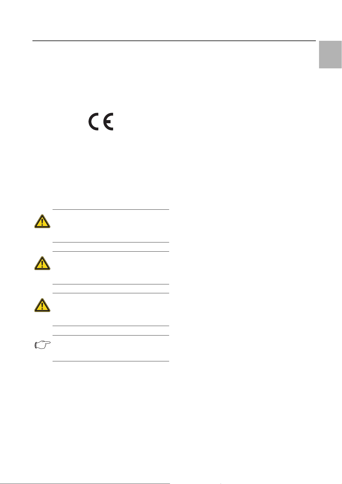
1.3 Symbols used in these operating instructions
The following symbols are used in this documentation:
Danger!
A dangerous situation in which failure to
comply with the instructions will result in
death or severe injury.
Warning!
A dangerous situation which may cause
death or serious injury if the instructions
are not followed.
Caution!
A dangerous situation which may lead to
(minor) injuries if the instructions are not
followed.
Note:
Important notices and indication of situations
which may result in material damage.
This symbol indicates an «action point» and shows that
you should perform an operation or procedure.
2 Safety notes
Please observe the following general safety notes when
assembling and operating the unit:
– Assembly, installation and servicing may only be per-
formed by properly trained specialists.
– Screw the enclosure to the floor to prevent it from tip-
ping over when the cooling unit is installed.
– Do not obstruct the air inlet and air outlet of the cooling
unit inside and outside the enclosure (see section4.2.2 «Layout of the electronic components in the
enclosure»).
– To ensure problem-free opening and closing of the en-
closure door, use a ride-up door roller (refer to the accessories in the Rittal Catalogue). This raises the door
slightly and balances out the weight of the cooling unit,
to prevent buckling of the door and associated seal
problems.
– The heat loss of the components installed in the enclo-
sure must not exceed the useful cooling power of the
cooling unit.
– Cooling units with item numbers: 3303.xxx, 3361.xxx,
3304.xxx, 3305.xxx, 3328.xxx, 3329.xxx and
3332.xxx must be transported in an upright position
and protected from tipping over.
– Units with item numbers 3302.xxx and 3366.xxx must
be transported lying flat.
– Shipping braces must be used when transporting a
unit that has already been mounted (on the enclosure).
A wooden structure made from square timbers or
boards to support the cooling unit at the bottom (see
fig. 1) is suitable for this purpose. The pallet should be
big enough to prevent the enclosure and cooling unit
overturning. If the cooling unit is mounted on a door,
ensure the door is kept closed during transport.
– Use only original spare parts and accessories
– Do not make any changes to the cooling unit other
than those described in these instructions or associat-
ed instructions.
– Risk of burns! On cooling units with automatic con-
densate evaporation, the surface of the thermal ele-
ment will get very hot during operation, and will remain
so for some time afterwards.
– The mains connector of the cooling unit must only be
connected and disconnected with the system de-en-
ergised. Connect the protective device specified on
the rating plate.
EN
1.4 Other applicable documents
Assembly and operating instructions in paper and digital
format are available for the unit types described here.
We cannot accept any liability for damage associated
with failure to observe these instructions. Where applicable, the instructions for any accessories used also apply.
Rittal enclosure cooling unit 3
EN
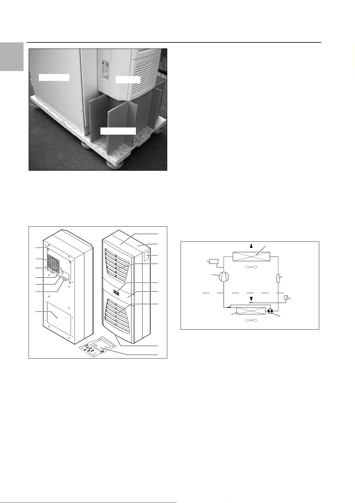
Enclosure
Support
Cooling unit
10
9
8
11
13
12
16
15
14
1
2
4
5
6
7
3
PSAH-
Pressure
switch
Condenser fan
Expansion valve (4)
Temperature
control
Filter dryer (5)
Internal circuit
Compressor (2)
External circuit
Evaporator fan
Evaporator coil (1)
Condenser (3)
3 Device description
Fig. 1: Transporting an enclosure/cooling unit combination
3 Device description
Depending on the model chosen, your cooling unit may
vary in appearance from the illustrations contained in
these instructions. However, the functions are identical
in principle.
15 Condensate discharge
16 Dispatch bag
3.1 TÜV-tested output measurement to
DIN EN 14511
All TopTherm cooling units in the output range from 300
to 4000 W are tested to the latest EN 14511-1-4:201312 standard by independent test institute TÜV Nord.
This means you have peace of mind about the design of
the climate control solution and you can be sure you are
getting the performance you are paying for.
3.2 Functional description
3.2.1 How it works
The cooling unit (compression refrigeration system)
comprises four main components (see fig. 3): the evaporator (1), the refrigerant compressor (2), the condenser
(3), and the control or expansion valve (4), which are
connected by suitable pipework. This circuit is filled with
a readily boiling substance, the refrigerant. The refrigerant R134a (CH
tion Potential (ODP) is 0, making it very eco-friendly. A filter dryer (5) which is integrated into the hermetically
sealed cooling circuit provides effective protection
against moisture, acid, dirt particles, and foreign bodies
within the cooling circuit.
FCF3) is chlorine-free. Its Ozone Deple-
2
Fig. 2: Device description
Key
1 Blind rivet nut
2Evaporator fan
3 Electrical wiring plan
4 X2 master-slave connection
5 X3 optional serial interface
6 X1 terminal strip
7 Air outlet hole
8 Front half of the enclosure
9 Rear half of the enclosure
10 Louvred grille for air outlet
11 Display
12 Infill panel
13 Louvred grille for air inlet
14 Rating plate
4 Rittal enclosure cooling unit
Fig. 3: Cooling circuit
In the evaporator coil (1), the liquid refrigerant is converted to a gaseous state. The energy needed for this purpose is taken from the enclosure air in the form of heat,
which has the effect of cooling the enclosure air. In the
compressor (2), the refrigerant is heavily compressed,
so that it achieves a higher temperature inside the condenser (3) than the ambient air. This means that excess
heat may be emitted to the ambient air via the surface of
the condenser, as a result of which the temperature of
the refrigerant drops and it is converted back into liquid.
It is re-injected into the evaporator coil via a thermostatic
expansion valve (4), which causes it to cool down further, and is then once again able to absorb the energy
from the enclosure air in the evaporator coil. The whole
cycle begins again.

3 Device description
3.2.2 Control
Rittal enclosure cooling units are fitted with a controller
for setting the functions of the cooling unit.
Depending on the design, this is either a Basic controller
(operating status display via LED) or an e-Comfort controller (display plus extended functions, see section6
«Operation»).
3.2.3 Bus mode (e-Comfort controller only)
The serial unit interface X2 allows you to create a bus
connection with up to ten cooling units using the masterslave cable (shielded, four-wire cable, Model No.
3124.100). This allows you to implement the following
functions:
– Parallel unit control (the cooling units in the network
can be switched on and off simultaneously)
– Parallel door status message («door open»)
– Parallel collective fault message
Data is exchanged via the master-slave connection.
During commissioning, assign an address to each unit
that also includes the identifier «master» or «slave».
3.2.4 Safety devices
– In the cooling cycle, the cooling units (with the excep-
tion of type 3302.xxx) have a tested pressure switch to
EN 12 263 which is set to maximum PS (permissible
pressure); this operates via an automatic reset device
whenever the pressure drops again
– Temperature monitoring prevents the evaporator coil
from icing over. If there is a risk of icing, the compres-
sor switches itself off and automatically switches itself
back on again at higher temperatures
– The refrigerant compressor and the fans are equipped
with thermal winding shields to protect against excess
current and excess temperatures
– In order to allow a reduction of pressure inside the
compressor and hence a safe restart, once it has been
switched off (e.g. upon reaching the set temperature
via the door limit switch function or via de-energising),
the device will switch back on with a delay of 180 sec-
onds
– The device has floating contacts on the connection
pins (terminals 3 – 5), via which system messages
from the device may be polled, e.g. using a PLC (1 x
change-over contact Basic controller, 2 x normally
open contacts e-Comfort controller)
3.2.5 Condensation
At high levels of humidity and low temperatures inside
the enclosure, condensation may form on the evaporator coil.
The cooling units (except 3302.xxx, 3303.xxx and
3361.xxx) have automatic, electric condensate evaporation. The thermal component used for this purpose is
based on self-regulating PTC technology. Condensate
arising on the evaporator coil is collected in a tank in the
external circuit of the cooling unit, and partially evaporated via the airflow. When the water level rises, the water
enters the PTC thermal component and is evaporated
(through-flow heater principle). The water vapour
streams out of the cooling unit with the airflow from the
external fan.
The PTC thermal component is permanently connected
and has no switchpoint. It is protected against short-circuits with miniature fuses (F1.1, F1.2). If the fuse has
tripped, any condensation is drained off via the safety
overflow.
For unit types 3302.xxx, 3303.xxx and 3361.xxx, the
condensate is routed downwards out of the unit via a
drain pipe on the evaporator coil divider panel. For this
purpose, a hose must be connected to the condensate
nozzle (see section4.4 «Connecting the condensate
discharge»). External condensate evaporators are available as accessories for these unit types (refer also to the
accessories in the Rittal Catalogue).
3.2.6 Filter mats
The entire cooling unit condenser is covered with a dirtrepelling, easy-to-clean RiNano coating. In many applications, therefore, the use of filter media is unnecessary,
particularly with dry dusts.
For dry, coarse dust and lint in the ambient air, we recommend installing an additional PU foam filter mat (available as an accessory) in the cooling unit. Depending on
the incidence of dust, you will need to replace the filter
mat from time to time.
For air containing oil condensate, we recommend the
use of metal filters (also available as an accessory).
These may be cleaned with suitable detergents and reused.
Function of the filter mat monitor (with e-Comfort controller only):
Dirt on the filter mat is automatically determined by
measuring the temperature difference in the external circuit of the cooling unit. As the level of filter mat soiling increases, the temperature difference will increase. The
setpoint value of the temperature difference in the external circuit adapts automatically to the relevant operating
points in the performance diagrams. Hence there is no
need to readjust the setpoint value for different unit operating points.
3.2.7 Door limit switch
The cooling unit may be operated with a floating door
limit switch connected. The door limit switch is not included with the supply (available as an accessory, Model
No. 4127.010).
The door limit switch function causes the fans and the
compressor in the cooling unit to be switched off after
approximately 15 seconds when the enclosure door is
opened (contacts 1 and 2 closed). This prevents the formation of condensation inside the enclosure while the
enclosure door is open. In order to prevent damage to
the unit, it is equipped with an ON delay: The evaporator
fan cuts back in with a delay of approximately 15 seconds after the door has been closed, while the condens-
EN
Rittal enclosure cooling unit 5
4 Assembly and connection
EN
er fan and compressor switch on after approximately
3minutes.
Note:
– No external voltage may be applied to the
door contacts (terminals 1 and 2).
– For cooling units with basic control, the
evaporator fan continues to run even
when the door is open.
3.2.8 Additional interface X3
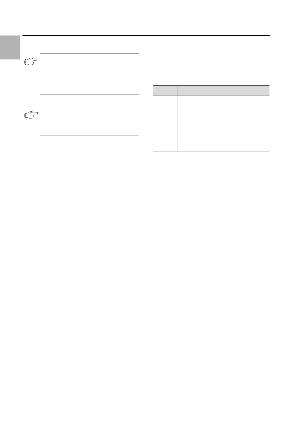
Note:
The electrical signals at the interface are of
an extra-low voltage (not extra-low safety
voltages to EN 60 335).
An additional interface card may be connected to the 9pole SUB-D connector X3 in order to incorporate the
cooling unit into higher-level monitoring systems (available as an accessory, interface card Model No.
3124.200).
3.3 Proper use, foreseeable misuse
The cooling unit is only intended for cooling connected
enclosures. Any other use is not permitted.
– The unit must not be installed and operated in loca-
tions which are accessible to the general public (see
DIN EN 60335-2-40, paragraph 3.119).
– The unit is designed solely for stationary use.
The cooling unit is state of the art and built according to
recognised safety regulations. Nevertheless, improper
use can pose a threat to the life and limb of the user or
third parties, or result in possible damage to the system
and other property.
Consequently, the cooling unit must only be used properly and in a technically sound condition! Any malfunctions which impair safety should be rectified immediately.
– Use of accessories not approved by Rittal GmbH &
Co. KG.
3.4 Scope of supply
The unit is supplied in a packaging unit in a fully assembled state.
Please check the scope of supply for completeness.
Qty. Description
1 Enclosure cooling unit
1
1
1
1
4 – 10
1 Drilling template
Tab. 1: Scope of supply
Dispatch bag:
– Assembly and operating instructions
–Self-adhesive tape
– Connector X1
–Grub screws
– Nuts, washers
4 Assembly and connection
4.1 Choosing the installation site
When choosing the installation site for the enclosure,
please observe the following:
– The site for the enclosure, and hence the arrangement
of the cooling unit, must be carefully selected so as to
ensure good ventilation (clearance between units and
clearance between the unit and the wall must be at
least 200 mm in each case).
– The cooling unit must be installed and operated in a
vertical position (maximum deviation: 2°).
– The installation site must be free from excessive dirt,
aggressive ambient conditions and moisture.
– The ambient temperature must be within the limits
specified on the rating plate.
– It must be possible to fit a condensate discharge (see
section4.4 «Connecting the condensate discharge»).
– The mains connection data as stated on the rating
plate of the unit must be guaranteed.
Proper use also includes the observance of the documentation provided, and compliance with the inspection
and maintenance conditions.
Rittal GmbH & Co. KG is not liable for any damage which
may result from failure to comply with the documentation provided. The same applies to failure to comply with
the valid documentation for any accessories used.
Inappropriate use may be dangerous. Examples of inappropriate include:
– Use of the cooling unit over long periods with the en-
closure open.
– Use of impermissible tools.
– Improper operation.
– Improper rectification of malfunctions.
6 Rittal enclosure cooling unit
4.2 Notes on assembly
4.2.1 General
– Check the packaging carefully for signs of damage.
Traces of oil on damaged packaging are an indication
of refrigerant loss and leakages. Any packaging damage may be the cause of a subsequent functional failure.
– The enclosure must be sealed on all sides (IP 54). In-
creased condensation will occur if the enclosure is not
airtight.
– In order to avoid excessive condensation inside the
enclosure, we recommend installing a door limit
switch (e.g. 4127.010) which deactivates the cooling
unit when the enclosure door is opened (see section3.2.7 «Door limit switch»).
4.2.2 Layout of the electronic components in the
enclosure
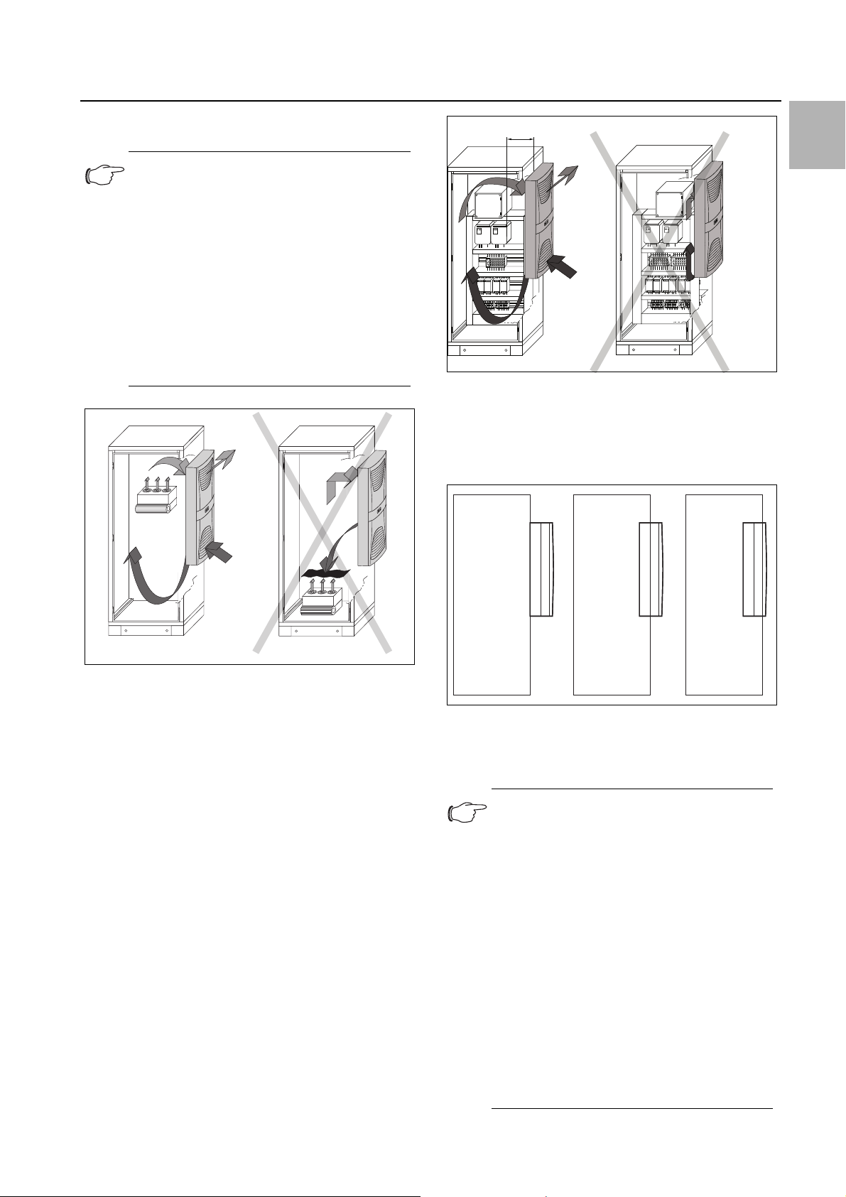
Note:
Risk of condensation!
When arranging the electronic components
inside the enclosure, please ensure that the
cold airflow from the cooling unit is not directed at active components. Please also
ensure that the cold airflow is not directed at
the warm exhaust airflow from active components such as converters. This may lead
to an air short-circuit and therefore prevent
adequate climate control, or may even
cause the cooling unit’s internal safety devices to cease cooling operation.
4 Assembly and connection
EN
Fig. 5: Air circulation inside the enclosure
4.3 Fitting the cooling unit
The enclosure cooling unit may optionally be externally
mounted on the enclosure (1), partially internally mounted (2) or fully internally mounted (3):
Fig. 4: Never direct the cold airflow at active components
Air diversion components are available as accessories –
please refer to the Rittal Catalogue.
It is important to ensure even air circulation inside the enclosure. Under no circumstances should air inlet and
outlet openings be obstructed, otherwise the cooling
performance of the unit will be reduced. Ensure the distance «x» (see fig. 5) from components and other installed enclosures so that the required air circulation is
not obstructed and prevented.
Fig. 6: Installation method
To this end, cut the side panel or door of the enclosure
as per the drilling template included with the supply, and
drill the relevant holes.
Note:
Units of type 3302.xxx and 3366.xxx can
only be either externally mounted or fully internally mounted.
Units of type 3332.xxx can only be either externally mounted or partially internally
mounted; they cannot be mounted in lockable doors on 600/1200 wide TS enclosures.
To mount units 3328.xxx, 3329.xxx and
3332.xxx in the TS side or rear panel, we
recommend using enclosure panel fasteners 8800.071 (see Rittal Catalogue). For
high dynamic loads and mounting on the
enclosure door, we recommend using reinforced door hinges 8800.710 (see Rittal
Catalogue). Units with protection category
NEMA 4X are only suitable for external
mounting.
Rittal enclosure cooling unit 7
EN
4 Assembly and connection
4.3.1 Making the cut-outs
Affix the supplied drilling template to the side panel or
door of the enclosure using adhesive tape.
There are dimensioning lines on the drilling template to
suit the various installation options for your cooling unit.
Using the dimension drawings (see Appendix), identify
the valid lines and dimensions for your installation type
on the drilling template.
Caution!
Carefully deburr all drilled holes and
cut-outs to prevent injuries caused by
sharp edges.
Fig. 9: Securing the cooling unit (3302.1xx only «external
mounting»)
Mark, drill and deburr the holes.
Make the cut-outs including the line width as per the
drilling template.
Deburr the cut-outs.
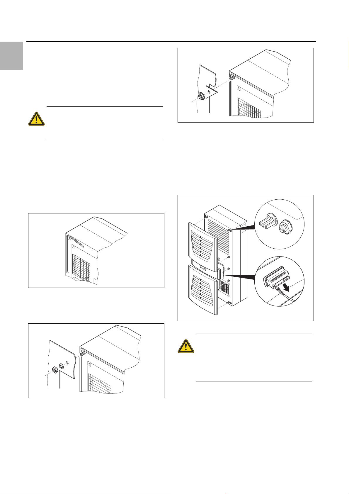
4.3.2 External mounting of the cooling unit
Cut the supplied sealing tape to the correct length and
stick it carefully along the back of the unit so that no
gaps are left at the joints.
Fig. 7: Applying the self-adhesive tape
Screw the supplied grub screws into the blind nuts on
the rear of the unit.
Secure the unit using the supplied washers and nuts.
4.3.3 Partial internal mounting of the cooling unit
Carefully remove the louvred grille and, where applica-
ble, the infill panel, from the enclosure by pulling forwards.
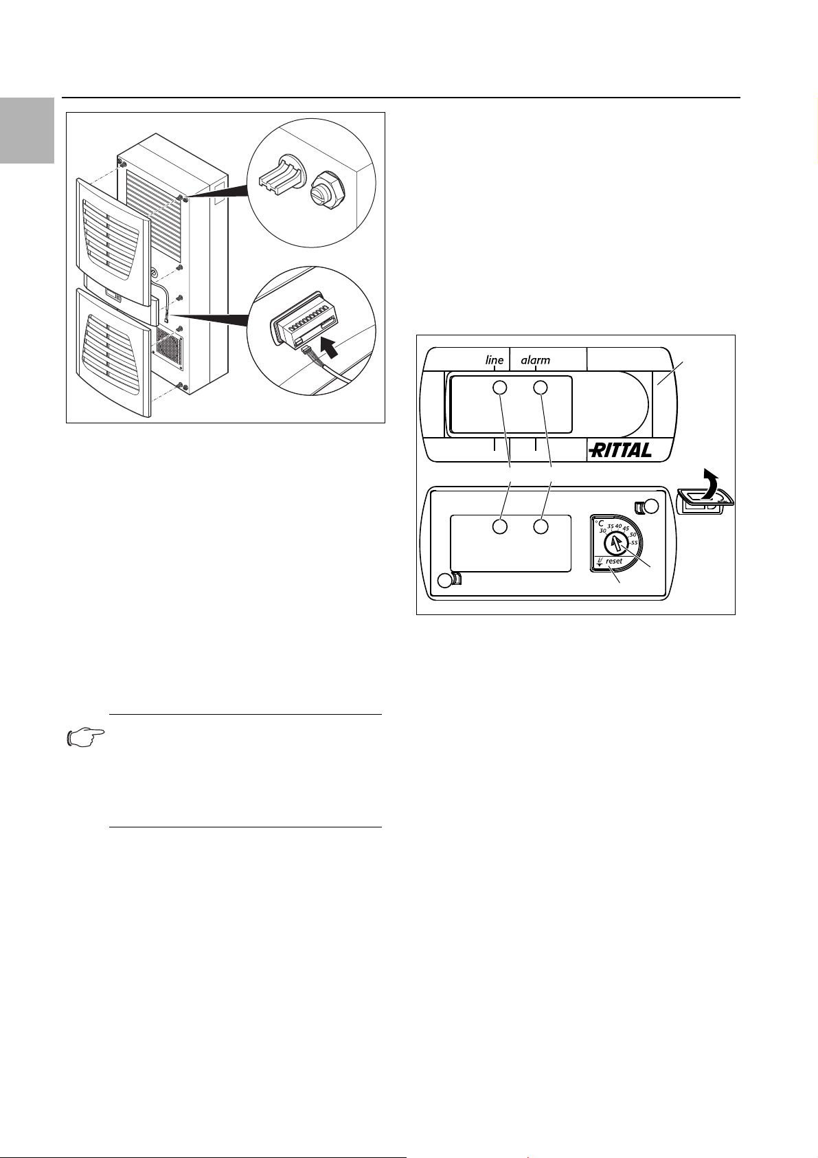
Carefully disconnect the connector from the rear of the
display and gently push it inwards through the cable
gland.
Fig. 10: Removing the louvred grille & disconnecting the display
Caution!
Stability of the cooling unit is only guaranteed in its assembled state. Brace
the rear half of the enclosure to prevent
it from falling over before removing the
front half.
Loosen the four nuts on the front half of the enclosure
Fig. 8: Securing the cooling unit (all models except 3302.1xx)
and pull the enclosure forwards by approx. 5 cm.
Loosen the flat-pin connectors of the PE conductor
between the two enclosure halves.
Disconnect the fan connection.
Remove the front enclosure tray completely.
8 Rittal enclosure cooling unit
4 Assembly and connection
EN
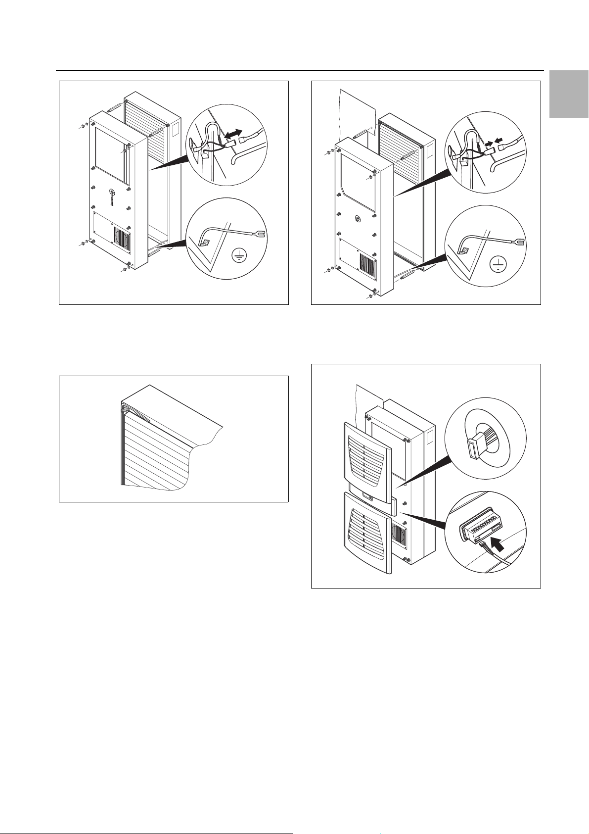
Fig. 11: Removing the cover
Remove the four spacer bolts.
Cut the supplied sealing tape to the correct length and
stick it carefully along the inside of the rear enclosure
half so that no gaps are left at the connection points.
Fig. 12: Applying the self-adhesive tape
Push the rear enclosure half into the mounting cut-out
and secure it with the four spacer bolts.
Push the display cable through the cable gland of the
front enclosure half.
Fig. 13: Securing the cooling unit
Connect the fan connector and PE conductor.
Mount the front enclosure tray using the washers and
nuts.
Fig. 14: Connecting the display connector
Carefully connect the display connector.
Push the louvred grille and, where applicable, the infill
panel, onto the enclosure.
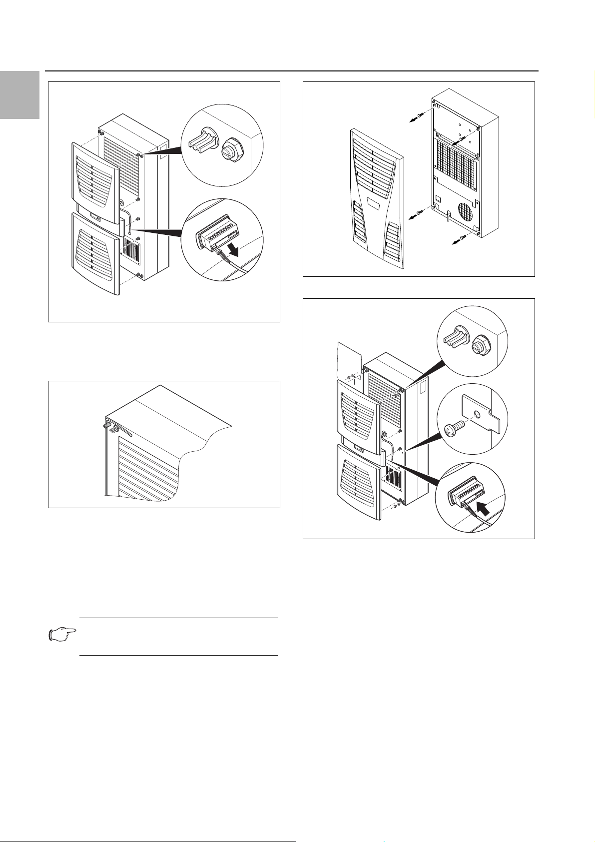
4.3.4 Full internal mounting of the cooling unit
Carefully remove the louvred grille and the infill panel
from the enclosure by pulling forwards.
Carefully disconnect the connector from the rear of the
display.
Rittal enclosure cooling unit 9
EN
4 Assembly and connection
Fig. 17: 3302.xxx only: removing the four screws
Fig. 15: Removing the louvred grille & disconnecting the display
Cut the supplied sealing tape to the correct length and
stick it carefully along the front enclosure half so that
no gaps are left at the connection points.
Fig. 16: Applying the self-adhesive tape
Loosen the four nuts and washers from the front en-
closure half.
Push the unit into the mounting cut-out from the inside
of the enclosure, and secure it to the enclosure from
the outside using the washers and nuts.
Only for 3302.xxx:
Fig. 18: Securing the cooling unit
Where necessary, additionally secure the unit using
the supplied mounting plates as shown in fig. 18.
Carefully connect the display connector.
Push the louvred grille and, where applicable, the infill
panel, onto the enclosure.
Note:
The tightening torque for the nuts is 6 Nm.
4.4 Connecting the condensate discharge
A condensate discharge hose can be fitted to all types
of cooling unit (except NEMA 4X devices).
Before installing, remove the four screws as shown.
The condensate discharge
– must be laid with a suitable and constant gradient (no
siphoning)
– must be laid without kinks
– must not have a reduced cross-section if extended
The condensate hose is available as an accessory (refer
also to Accessories in the Rittal Catalogue).
10 Rittal enclosure cooling unit
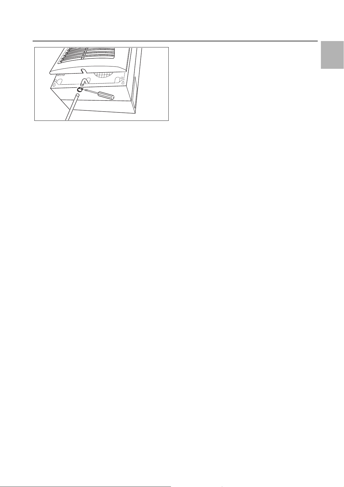
Fig. 19: Connecting the condensate discharge
Connect a suitable hose to the condensate nozzle and
secure using a hose clip.
Route the condensate hose to a drain or into the ex-
ternal condensate evaporator (refer to Accessories in
the Rittal Catalogue).
4.5 Notes on electrical installation
When performing the electrical installation, it is important
to observe all valid national and regional regulations as
well as the provisions of the responsible power supply
company. The electrical installation may only be carried
out by a qualified electrician who is responsible for compliance with the applicable standards and regulations.
4.5.1 Connection data
– The connected voltage and frequency must corre-
spond to the values stated on the rating plate
– The cooling unit must be connected to the mains via
an all-pin isolating device, which ensures at least
3 mm contact opening when switched off
– No additional temperature control may be connected
upstream of the unit at the supply end
– Install the protective device specified on the rating
plate to protect the line and equipment from short-circuits.
– The mains connection must ensure low-noise poten-
tial equalisation
4.5.2 Overvoltage protection and supply line load
– The unit does not have its own overvoltage protection.
Measures must be taken by the operator at the supply
end to ensure effective lightning and overvoltage protection. The mains voltage must not exceed a tolerance of ±10%.
– In accordance with IEC 61 000-3-11, the unit is in-
tended solely for use at sites with a continuous current-carrying capacity (incoming mains power supply)
of more than 100 A per phase and with a supply voltage of 400/230 V. If necessary, the electricity supply
company must be consulted to ensure that the continuous current-carrying capacity at the point of connection to the public grid is sufficient for connection of
such a unit.
– The fans and compressors in single- and three-phase
units are intrinsically safe (thermal winding protection).
This also applies to transformer versions, types
4 Assembly and connection
3304.510, 3305.510, 3328.510 and 3329.510, and to
special-voltage units which are likewise equipped with
a transformer.
– Install the protective device specified on the rating
plate to protect the line and equipment from short-circuits (miniature circuit-breaker with appropriate characteristic – e.g. «K» characteristic – or gG standard
type slow fuse, circuit-breaker for plant or transformer
protection). Select a suitable circuit-breaker in accordance with the information specified on the rating plate:
Set it to the minimum specified value. This will achieve
the best short-circuit protection for cables and equipment. Example: Specified setting range 6.3 – 10 A; set
to 6.3 A.
4.5.3 Three-phase devices
– The electrical connection for devices in the three-
phase version MUST be made with a clockwise rotating field
– The three-phase version of models 3304.xxx,
3305.xxx, 3328.xxx, 3329.xxx and 3332.xxx must be
connected to a TN network with star earthing via a circuit-breaker for plant protection (current setting as per
the rating plate). Three-phase units with special voltages must be protected with a circuit-breaker for
transformer protection (category AC-3) as per the rating plate.
– Units designed for three phase 400/460 V feature ad-
ditional monitoring of the rotary field or the absence of
a phase. If the rotary field is incorrect or a phase is absent, the unit will not run.
4.5.4 Door limit switch
– Each door limit switch must only be assigned to one
cooling unit.
– Several door limit switches may be connected in par-
allel to one cooling unit.
– The minimum cross-section for the connection cable
is 0.3 mm
– The line resistance to the door limit switch must not
exceed a maximum of 50 .
– The door limit switch only supports a floating connec-
tion; no external voltages.
– The contact of the door limit switch must be closed
when the door is open.
The safety extra-low voltage for the door limit switch is
provided by the internal power pack: Current approx.
30 mA DC.
Connect the door limit switch to terminals 1 and 2 of
the connector.
4.5.5 Notes on the flicker standard
The flicker limits specified in standard EN 61 000-3-3 or
-3-11 are adhered to, provided the supply impedance is
less than approx. 1.5 .
Where necessary, the unit operator should measure the
connected impedance or consult the responsible electricity supply company. If there is no way of influencing
2
for a cable length of 2 m.
EN
Rittal enclosure cooling unit 11
EN
Mounting device
rear panel
Fastening to 35 mm
support rail
DIN EN 50 022
Mains connection for
Cooling unit
Customer-side
connection
230 V
4 Assembly and connection
the supply impedance and sensitive installed components (e.g. BUS) are subjected to interference, a line reactor or starting-current limiting device should be connected upstream of the cooling unit to restrict the startup current of the cooling unit.
4.5.6 Potential equalisation
If, for EMC reasons, the unit is to be integrated into the
customer’s existing potential equalisation system, a
conductor with a larger nominal cross-section can be
connected to the potential equalisation connection point
(attachment points) on the wall-mounted cooling units.
According to the standard, the PE conductor in the
mains connection cable is not classified as an equipotential bonding conductor.
4.6 Making the electrical connection
4.6.1 Bus connection
(only when interconnecting several units
with a Comfort controller)
When using several cooling units, the serial device interface X2 can be used to connect up to ten cooling units
with the bus cable (Model No. 3124.100).
Fig. 20: Mounting external transformer (3361.x40 only)
When interconnecting, please note the following:
– De-energise the cooling units to be connected
– Ensure proper electrical insulation
– Make sure the cables are not laid in parallel to power
– Make sure that the lines are short
4.6.2 Connection X3 for serial interface
The interface card (Model No. 3124.200) may be connected to X3. This is used to evaluate system messages
in a PLC, for remotely setting parameters and monitoring, or for integration into the facility management system.
lines
Note:
The electrical signals at the X2 interface are
of an extra-low voltage (not extra-low safety
voltages in accordance with EN 60 335-1).
Note:
With the last slave unit in the group, do not,
under any circumstances, connect the remaining socket of the Y cable 3124.100 into
interface X3 of the cooling unit!
4.6.3 Mounting external transformer
Only for 3361.x40.
12 Rittal enclosure cooling unit
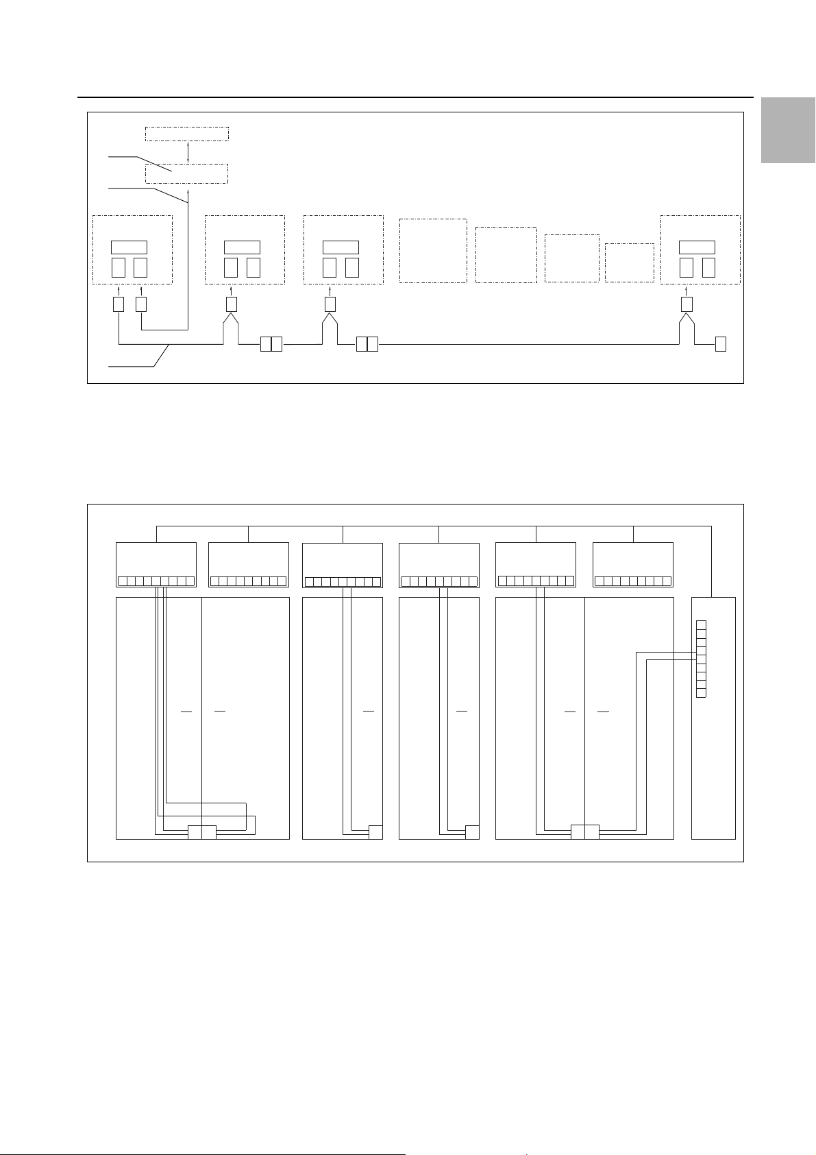
Fig. 21: Connection example: Master-slave operation
X2
CMC
I/O unit
RTT
Master
Adr.: 09
X1
X2
X3
X1
X2
X3
X1
X2
X3
X1
X2
X3
X2
X3
X2
X2
X2
X2
X2
X2
St. St. St.
Bu.
St.
Bu.
X2
Adr.: 11 Adr.: 12RTT
Slave
RTT
Slave
Adr.: 19RTT
Slave
St.
Bu.
St.
Bu.
3
2
1
X10
L1
L2
N
PE
1
2345
1
X10
X10 X10 X10 X10
X2 X2 X2 X2 X2 X2
X2
L1
PE
1
2345
L1
L2
N
PE
1
2345
L2 L3
L1
PE
1
2345
L2 L3
L1
PE
1
2345
L2 L3
L1
PE
1
2345
L2 L3
L1
L2
N
PE
1
23
4
5
X10
2
3
4
56
1
Adr.: 06 Adr.: 11 Adr.: 12 Adr.: 13 Adr.: 14 Adr.: 15
22 2 2 2
34432
Adr.: 16
Key
1 Serial interface (Model No. 3124.200)
2 Serial interface cable
3 Master-slave bus cable (Model No. 3124.100)
RTT Rittal TopTherm cooling units
X1 Supply connection/door limit switch/alarms
4 Assembly and connection
EN
X2 Master/slave connection Sub-D, 9-pole
X3 Serial interface Sub-D, 9-pole
St. Sub-D connector, 9-pole
Bu. Sub-D jack, 9-pole
Adr. Address
Fig. 22: Connection example: Door limit switch and master-slave operation
Key
1 Master cooling unit
2 Slave cooling units
3 2-door enclosure with two door limit switches
4 Enclosure with door limit switch
Rittal enclosure cooling unit 13
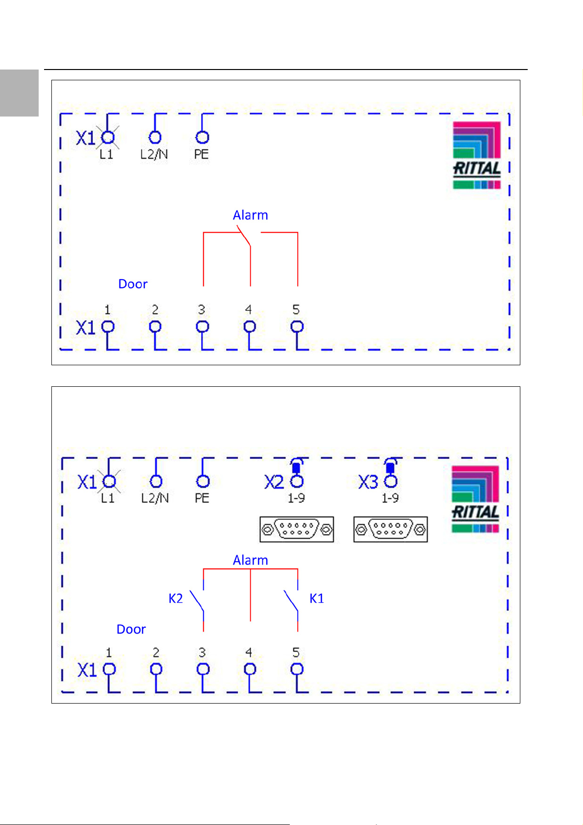
4.6.4 Installing the power supply
Complete the electrical installation by following the
wiring plan on the rear of the cooling unit (see fig. 2, for
key see page 15).
If you would like the system messages from the cool-
ing unit to be evaluated via the system message relay,
you should also connect a suitable low-voltage cable
to terminals 3 – 5.
EN
3302.100/.110, 3302.300/.310
3303.500/.510, 3303.600/.610, 3361.500/.510, 3361.600/.610, 3361.540/.640
3304.500/.510/.504/.514/.520/.600/.610
3305.500/.510/.504/.514/.520, 3328.500/.510/.504/.514/.520, 3329.500/.510/.504/.514/.520,
3305.600/.610, 3328.600/.610, 3329.600/.610, 3366.500/.510/.600/.610
4 Assembly and connection
Fig. 23: Electrical wiring plan no. 1
Fig. 24: Electrical wiring plan no. 2
14 Rittal enclosure cooling unit
4 Assembly and connection
3304.540/.544, 3305.540/.544, 3328.504/.544, 3329.504/.544
3304.640, 3305.640, 3328.640, 3329.640, 3366.540/.640, 3332.540/.640
EN
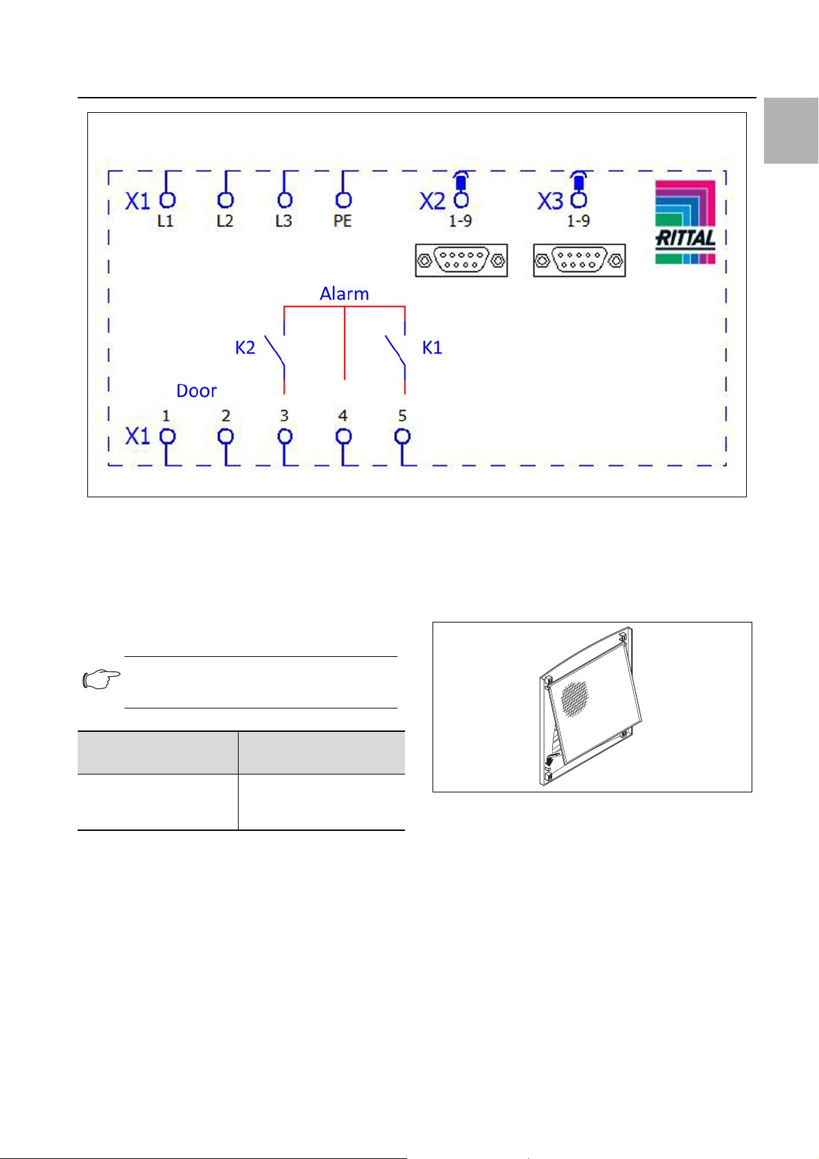
Fig. 25: Electrical wiring plan no. 3
Key
X1 Main terminal strip
X2 Master/slave connection
X3 Optional interface
K1 Relay collective fault 1
K2 Relay collective fault 2
Door Door limit switch (without door limit switch: terminal 1, 2
open)
textile plants with heavy lint contamination, lint screens
should be used (available as an optional extra).
Pull the louvred air inlet grille off the enclosure.
Insert the filter mat into the louvred grille as shown in
fig. 26 and push it back onto the enclosure.
Note:
For technical data, refer to the rating plate.
AC
cos φ = 1
I max. = 2 A
U max. = 250 V
Tab. 2: Relay contact data
4.7 Finalising assembly
4.7.1 Installing the filter media
DC
Res. Load
I min. = 100 mA
U max. = 30 V
I max. = 2 A
Fig. 26: Installing the filter mat
4.7.2 Fitting the cooling unit
For partial and full internal mounting only.
Connect the connector to the rear of the display.
Place the louvred grille onto the unit at the front, and
press it down until you hear it snap into place.
The entire cooling unit condenser is covered with a dirtrepelling, easy-to-clean RiNano coating. In many applications, therefore, the use of filter media is unnecessary,
particularly with dry dusts.
For dry, coarse dust and lint in the ambient air, we recommend installing an additional PU foam filter mat (available as an accessory) in the cooling unit. For air containing oil condensate, we recommend the use of metal filters (also available as an accessory). When used in
Rittal enclosure cooling unit 15
EN
5 Start-up
Fig. 27: Connect the display and attach the louvred grille
4.7.3 Setting the filter mat monitor
(only with e-Comfort controller)
Function of the filter mat monitor:
Dirt on the filter mat is automatically detected by meas-
uring the temperature difference in the external circuit of
the cooling unit (see section6.2.6 «Programming overview»). As the level of filter mat soiling increases, the
temperature difference will increase. The setpoint value
of the temperature difference in the external circuit
adapts automatically to the relevant operating points in
the performance diagrams. Hence there is no need to
readjust the setpoint value for different unit operating
points.
5 Start-up
Note:
The oil must be collected in the compressor
in order to ensure effective lubrication and
cooling.
Do not operate the cooling unit for at least
30 minutes after assembling the equipment.
Once all the assembly and installation work is com-
plete, switch on the power supply to the cooling unit.
The cooling unit starts running:
– With Basic controller: The green operating LED («line»)
is illuminated.
– With e-Comfort controller: The software version of the
controller first appears for approx. 2 seconds, then
«ECO» to show Eco mode is enabled. The internal en-
closure temperature will then appear in the 7-segment
display
You can now make your individual settings on the unit,
e.g. set the temperature or (with e-Comfort controller
only) assign the network identifier, etc. (refer to section6
«Operation»).
6 Operation
You can operate the cooling unit using the controller on
the front of the device (fig. 2, item 11). Depending on the
model, the unit is equipped with a Basic or e-Comfort
controller.
6.1 Control using the Basic controller
For Model Nos. 3302.xxx.
Fig. 28: Basic controller
Key
1 Controller trim panel
2 Temperature setter
3 LED green («line»)
4 LED red («alarm»)
5 Reset button
6.1.1 Properties
– Rated operating voltage: 115 V or 230 V
– Integral start-up delay and door limit switch function
– Protective function to prevent icing
– Monitoring of all motors (compressor, condenser fan,
evaporator fan)
– Phase monitoring for three-phase units
– Visualisation of the operating status via LED display:
– Voltage on, unit operational
– Door open (only if door limit switch installed)
– Warning of overtemperature
– High-pressure monitor has switched
– Switching hysteresis: 5 K
If the cooling unit and compressor run times are too
long < 1 minute, the switching hysteresis to protect
the cooling unit is automatically increased.
– Floating system message contact in case of overtem-
perature
16 Rittal enclosure cooling unit
6 Operation
– Temperature setting
(setting range 30 – 55°C) via potentiometer
– Test function
– Flashing mode to indicate system messages.
See section6.1.2 «Operating and error display»
The cooling unit operates automatically, i.e. after switching on the power supply, the evaporator fan (see fig. 3)
will run continuously and permanently circulate the inter-
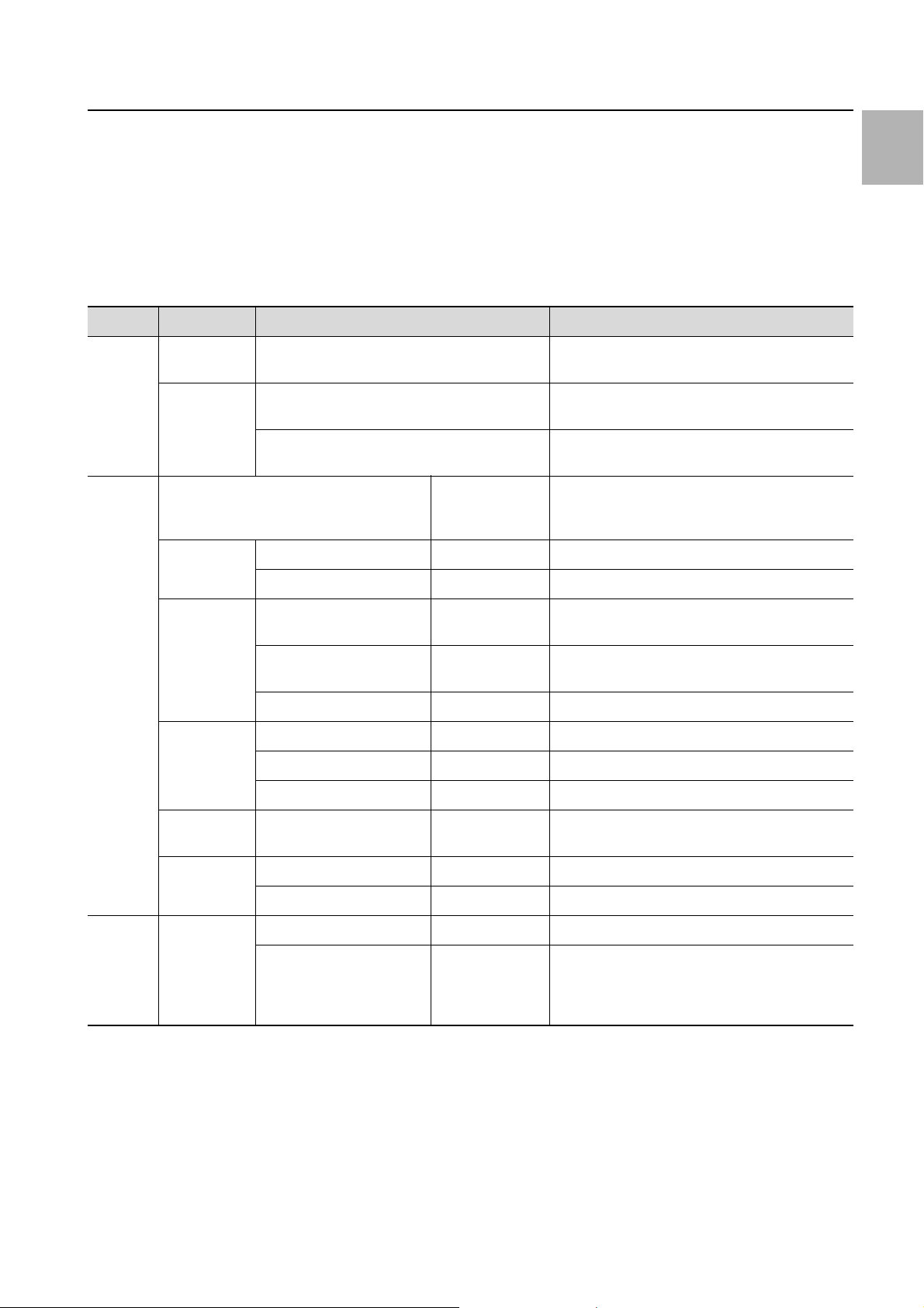
LED Status Cause Solution
Green
(line)
Red
(alarm)
Illuminated Power supply on,
unit operational
Flashing Only with door limit switch installed:
enclosure door open
Only with door limit switch installed:
enclosure door closed
Alarm/error/warning Number of flash
a
Implement
reset
Device reset (12) |_|_|_|_|_|_|_|_|_|_|_|*****|_|_|_|_|_|_|_|_|_|_|_|
High pressure alarm (0) |_|_|_|_|_|_|_|_|_|_|_|_|_|_|_|_|_|_|_|_|_|_|_|_|_|
nal enclosure air. The built-in Basic controller ensures
automatic normal shut-down operation of the cooling
unit by the value of the fixed preset switching difference
of 5 K.
6.1.2 Operating and error display
The Basic controller monitors and controls the cooling
unit. It indicates the operating and error status via the
green and red LEDs (fig. 28, items 3 and 4):
–
In order to avoid condensation, close the enclosure door as quickly as possible.
Check the position of the door limit switch.
Flash interval
intervals for the
red LED
EN
Sensors Potentiometer defective or
display error
Internal temperature
sensor defective
Anti-icing sensor defective (5) |_|_|_|_|*****|_|_|_|_|*****|_|_|_|_|*****|_|_|_|_|
Overload Compressor overloaded (6) |_|_|_|_|_|*****|_|_|_|_|_|*****|_|_|_|_|_|*****
Interior fan overloaded (7) |_|_|_|_|_|_|*****|_|_|_|_|_|_|*****|_|_|_|_|_|_|
Exterior fan overloaded (8) |_|_|_|_|_|_|_|*****|_|_|_|_|_|_|_|*****
Device status/state
Warning Anti-icing alarm (2) |_|*****|_|*****|_|*****|_|*****|_|*****|_|*****|_|
Off No display No power – Check power supply
Tab. 3: Operating and error display on the Basic controller
Overload mode
(heat loss)
Overtemperature warning (1) |*****|*****|*****|*****|*****|*****|*****|*****|*****|
Rotary current phase
toring:
«LED off» = Incorrect
phase connection
moni-
(3) |_|_|*****|_|_|*****|_|_|*****|_|_|*****|_|_|*****
(4) |_|_|_|*****|_|_|_|*****|_|_|_|*****|_|_|_|*****
(9) |_|_|_|_|_|_|_|_|*****|_|_|_|_|_|_|_|_|*****
– Swap phases
Key to flash intervals
| = 500 ms (red LED on)
_ = 500 ms (red LED off)
***** = 3 s pause (red LED off)
nection diagrams under section4.6.4 «Installing the
power supply»):
– Terminal 3: NC (normally closed)
– Terminal 4: C (connection of the supply voltage to the
fault signal relay)
The overtemperature message may also be polled via an
integral floating contact on the cooling unit terminal (system message relay with changeover contact, see con-
Rittal enclosure cooling unit 17
– Terminal 5: NO (normally open)
The NC and NO definitions refer to the de-energised
state. As soon as power is applied to the cooling unit,
6 Operation
EN
the system message relay picks up, so that the relay
contacts change status (contact 3 – 4 open; contact 4 –
5 closed).
This is the normal operating state of the cooling unit. As
soon as an error message occurs or the power supply is
interrupted, the relay drops out and contact 3 – 4 is
closed.
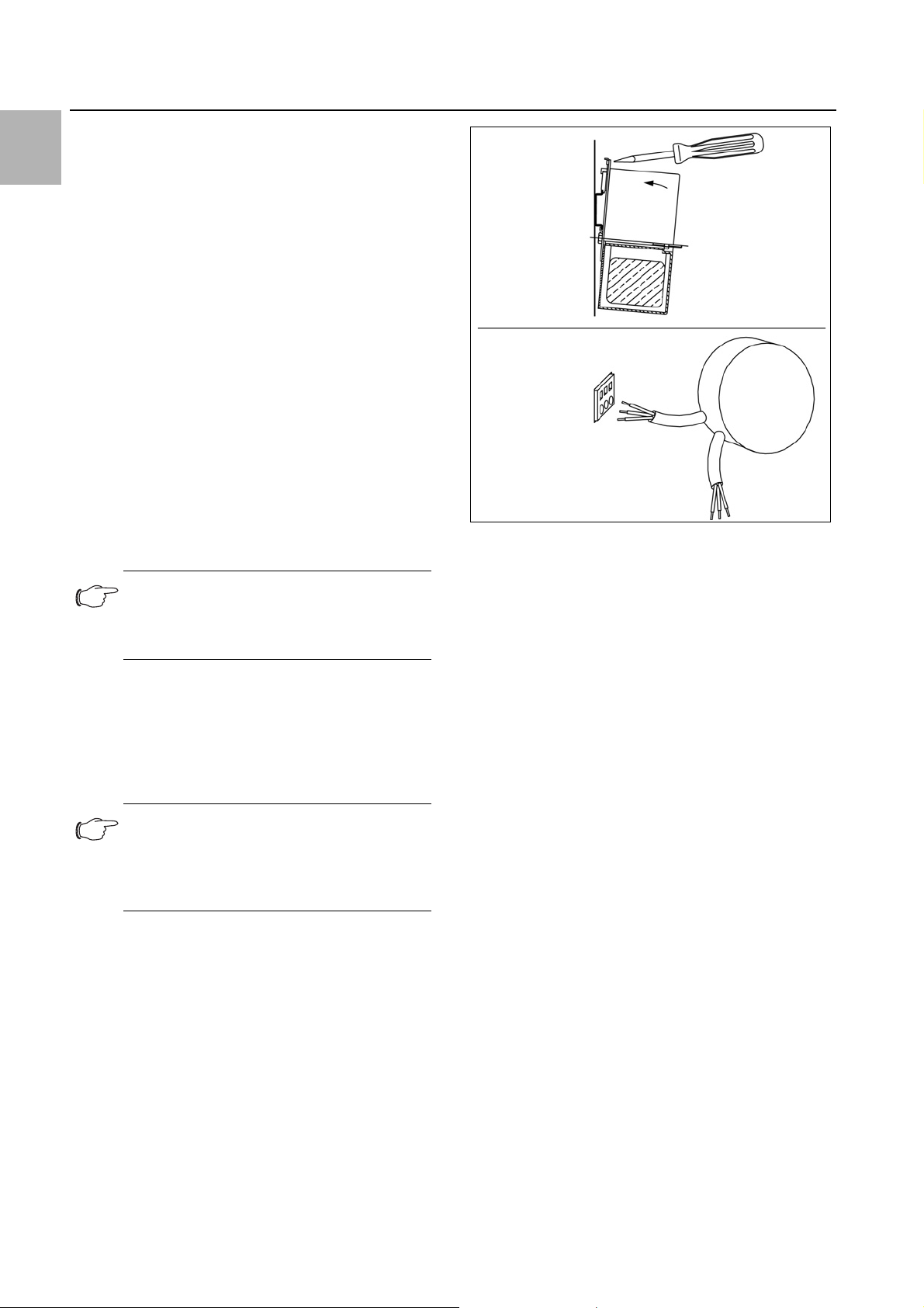
6.1.3 Test mode with the Basic controller
The Basic controller is equipped with a test function
whereby the cooling unit commences cooling operation
independently of the set temperature or door limit switch
function.
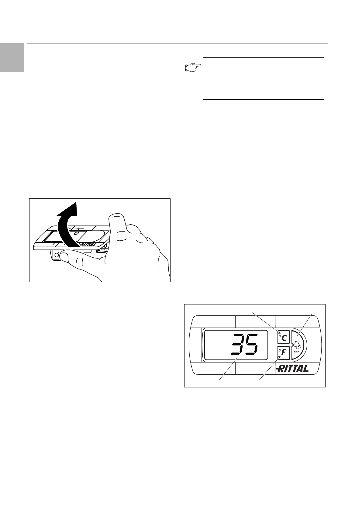
First you must remove the controller trim panel.
Switch off the mains voltage.
Remove the louvred grille or infill panel in which the
controller is installed.
Release the display lock from behind and pull it for-
wards slightly.
6.1.4 Setting the temperature
Note:
With the Basic controller, the temperature is
preset at the factory to +35°C.
In order to save energy, do not set the temperature lower than that actually necessary.
To change the temperature setting:
Take the trim panel off the controller as described in
section6.1.3 «Test mode with the Basic controller».
Set the required temperature on the temperature set-
ting device (fig. 28).
Carefully push the trim panel onto the display until you
hear it snap into place.
Push the display back into the infill panel or louvred
grille.
Re-attach the louvred grille or infill panel to the cooling
unit.
6.1.5 Resetting the Basic controller
Following a high-pressure alarm in the cooling cycle, and
once the cause has been rectified, you will need to manually reset the Basic controller:
Take the trim panel off the Basic controller as de-
scribed in section6.1.3 «Test mode with the Basic
controller».
Press the reset button (fig. 28, item 5) for at least
3seconds.
The red LED is extinguished.
Re-install the Basic controller.
Fig. 29: Releasing the Basic controller trim panel
Carefully lift the trim panel, e.g. using your thumb or a
flat screwdriver, and remove it.
You can now start test mode.
Rotate the potentiometer to the left-hand stop, then
hold the rubberised potentiometer display down while
you re-connect the mains voltage.
The cooling unit will commence operation and the green
LED will flash (I_II_I_II_. ..). Test mode is completed after
approximately 5 minutes. The unit switches off and
changes to normal operation.
Key
I = LED 500 ms on
_ = LED 500 ms off
In normal operation, the green LED is permanently illuminated.
Next, rotate the potentiometer back to the required
setpoint.
6.2 Control using the e-Comfort controller
For unit types 33xx.5xx and 33xx.6xx.
Fig. 30: e-Comfort controller
Key
1 Programming button, also display of the set temperature
unit (degrees Celsius)
2 Set button
3 Programming button, also display of the set temperature
unit (degrees Fahrenheit)
47—segment display
18 Rittal enclosure cooling unit
Loading…
Поиск по каталогу продукции
Поиск по каталогу
>
>
>
Каталоги RITTAL | Информационная поддержка клиентов
Архив
Архивные каталоги можно только скачать для ознакомления.
Therm
Программа для расчета контроля микроклимата промышленных шкафов
Программное обеспечение Therm полностью берет на себя трудоемкий расчет необходимой мощности системы контроля микроклимата. Интуитивно понятная оболочка позволяет выбрать подходящее оборудование контроля микроклимата, с учетом требуемой мощности. В конце расчета Вы получаете детальный документ, который можно распечатать или сохранить в предпочтительном для Вас текстовом формате. Это обеспечивает максимальную надежность при расчете микроклимата промышленных шкафов.
Все результаты расчетов соответствуют стандартам IEC/TR 60 890 AMD1/02.95 и DIN 3168 для холодильных агрегатов распределительных шкафов. Расчет превышения температуры согласно DIN EN 61439 можно выполнить в Therm одним щелчком мыши.
Вы получаете итоговый документ
- Рассчитанная эффективная поверхность шкафа
- Излучаемая в окружающее пространство или поглощаемая из окружающего пространства тепловая мощность
- Необходимая мощность охлаждения
- Температура внутри шкафа без контроля микроклимата
- Предложение по возможным решениям
- 17 языков интерфейса
- Редактируемая база данных по тепловыделению стандартных компонентов
- Расчеты производятся в соответствии со стандартами МЭК/TR3 60890 AMD 1 и DIN 3168
- Результаты со всеми исходными данными могут быть распечатаны и сохранены в файл, а также отредактированы с помощью текстового редактора
- Возможен одновременный расчет для нескольких промышленных шкафов
- 500 МБ свободного пространства на жестком диске
- Microsoft Internet Explorer версии 8.0 или выше либо Mozilla Firefox 28.0 или выше
- Процессор с частотой 2,0 ГГц
- Windows 2000 или XP: Pentium 4, Celeron или аналогичный процессор AMD, ОЗУ 512 МБ
- Windows Vista, 7 или 8: процессор Dual-Core или аналогичный, ОЗУ 1 ГБ
- Проверка превышения температуры согласно DIN EN 61439: всего одним щелчком мыши генерируется pdf-документ в соответствии с требованиями DIN.
- Интеграция с Eplan ProPanel: все необходимые для расчета микроклимата параметры автоматически передаются в Therm 6.3. Результаты расчета также передаются обратно в ProPanel, где выбранное решение по контролю микроклимата автоматически отображается в проекте в виде 3D-модели.
- Улучшение сетевых опций: Предупреждение при одновременном использовании проектов, утверждение проектов.
- Отображение подходящих чиллеров при применении воздухо-водяных теплообменников.
- Актуализированная база данных.
Последнее обновление
Инструкция к онлайн версии Rittal Therm 6.3
Для того, чтобы воспользоваться онлайн версией Rittal Therm 6.3, необходимо сначала создать аккаунт. Для этого в поле «User» введите Вашу электронную почту, а в поле «Password» введите пароль «1234GK-M» (без кавычек). После этого Вам будет предложено сменить этот пароль на собственный.
источник
Обзор прецизионных кондиционеров Rittal: коды ошибок, сравнение шкафных моделей
Компания Rittal берет свое начало в 1961 году. Основное направление производства – это разработка распределительных шкафов, контроль микроклимата, электрораспределение и компьютерные инфраструктуры. Сервисы по продаже, поддержке и ремонту, на данный момент, распространены по всему миру.
Классификация выпускаемой продукции
Настенные холодильные агрегаты или же шкафные кондиционеры Rittal – это та продукция, которой на производстве уделяет особое внимание. Компания выпускает несколько линеек, способных удивить большое количество пользователей, несмотря на свою специфичность и узконаправленное использование.
Blue e+
Благодаря современным технологиям производства энергоэффективность повысилась до небывалого уровня. Если быть точнее, то использование гибридной технологии привело к экономии ресурса до 75%. Дают такой результат компоненты, помогающие регулировать число оборотов, и «тепловые трубки». В больших серверных сохранение такого ресурса, как электричество, это трудный процесс и, практически, первоначальная задача, после охлаждения, которая ставится перед подобным оборудованием. Обусловлено это и без того большими затратами.
Щитовые кондиционеры Rittal могут использоваться во всем мире, так как поддерживаются различные напряжения, что позволяет подключить устройство к любому доступному источнику электричества. Вся настройка осуществляется с помощью сенсорного экрана, который элегантно скрыт на передней панели устройства.
Для более удобного управления существует мобильное приложение, разработанное специально для рассматриваемой линейки. С помощью смартфона можно управлять агрегатом, сохранять необходимую информацию и даже отправлять заявку на ремонт или заказ запасных частей.
Установка кондиционера не должна стать проблемой. Кроме простого монтажа, шкафная сплит-система Rittal может быть поставлена в углубление или просто на пол. Для фиксации есть рым-болт и специальный зажим. Переноска же становится удобной из-за того, что производитель предусмотрел специальную ручку.
Самая мощная система из рассматриваемой линейки – SK 3189.940. такой показатель при охлаждении достигает отметки в 5,8 кВт, что является достаточно большим числом для кондиционирования в подобной сплит-системе.
TopTherm
Более компактные холодильные агрегаты с достаточно неплохой мощностью охлаждения, для своего размера, которая равна всего лишь 300 Вт. Существует несколько видов исполнения такой модели, горизонтальное и вертикальное. Установка его точно такая же, как и у предыдущей модели. Нельзя только сказать того же про ремонт кондиционера Rittal рассматриваемой линейки, так как смартфон здесь уже не подключается.
Более подробное описание в данном случае невозможно, так как рассматриваемая сплит-система является лишь просто небольшим аналогом предыдущей. Пользование ею актуально только в исключительных случаях, например, оправдано ее применение в небольших серверных, где основная задача – это охлаждение лишь одного аппарата, создающего локальную сеть.
TopTherm Blue e
Аналогичные агрегаты, но уже с более мощными комплектующими, которые могут управляться со смартфона. Отличия от предыдущего варианта есть еще и в том, что технология «Blue e+» – это настоящая экономия электроэнергии. Сам производитель заявляется, что выбросы CO2 будут снижены на 30 процентов, а потребление электричества сократится до 50%, если брать эту часть от того же агрегата, но без такой системы.
TopTherm Blue e, NEMA 4X
Это шкафной кондиционер Ритал, который сочетает в себе все преимущества предыдущих моделей, при этом выполнена по технологии «Blue e». Мощность при охлаждении зависит от того, какая модель будет выбрана покупателем. Если это SK 3303.504, то показатель будет достигать всего лишь 550 Вт. Для более высоких задач лучше подойдет SK 3329.544, мощность которой достигает 2750 Вт.
Так или иначе, любой из этих шкафов выполняют одну функцию – охлаждение. Использование таких установок в домашних условиях невозможно, поэтому встретить подобные агрегаты представляется возможным лишь на предприятиях, например, в серверных, где обязательно поддержание одной температуры в течение круглых суток.
Сравнение популярных моделей
Для более понятного сравнения моделей между собой необходимо привести таблицу, где будут использованы только сухие цифры, ясно показывающие разницу.
| Характеристика | SK 3186.930 | SK 3188.940 | SK 3189.940 |
| Материал | Листовая сталь | Листовая сталь | Листовая сталь |
| Полная мощность охлаждения | 1,29 кВт | 5,8 кВт | 4,2 кВт |
| Регулирование температуры | Контроллер e+ | Контроллер e+ | Контроллер e+ |
| Коэффициент энергоэффективности | 3,5 | 2,64 | 3,46 |
| Диапазон температур хранения | -40°C…+70°C | -40°C…+70°C | 40°C…+70°C |
Инструкции к пульту управления и кондиционерам Rittal
Инструкция на русском языке содержит весьма полезный материал по возможностям такой системы и ее монтажу. Пульт для кондиционера не предусматривается, поэтому управление ею производится либо непосредственно на панели, либо, в отдельных случаях, с помощью смартфона и специального программного обеспечения. К слову, как решить проблемы с некоторыми неисправностями также написано в русскоязычном руководстве, причем достаточно подробно.
Особое внимание производитель акцентирует на следующем:
- Не должно быть препятствий на входе горячего воздуха и выхода холодного.
- Воздух во внутреннем контуре должен циркулировать беспрепятственно.
- Расстояние между стеной и выходом воздуха не должно быть менее 200 мм.
- Если устройство отключено, то запускать его можно не ранее, чем через 5 минут после выключения.
Коды ошибок кондиционеров Rittal
Проводить диагностику такого устройства проще простого. Все кодовые сообщения появляются на центральном дисплее агрегата с припиской «H1». После этого ставится двоеточие и выводится цифра конкретной проблемы. Все это происходит попеременно с показателями температуры в интервале двух секунд.
Более подробные данные можно получить из таблиц кодов ошибок, которые можно найти в руководстве по эксплуатации.
Отзывы пользователей
Для более объективного мнения о качестве продукции компании Rittal необходимо выделить основные достоинства и недостатки основных линеек. Формировать такие списки лучше всего на основе реальных отзывов покупателей, так как это повышает информативность и все полученные данные абсолютно объективны и непредвзяты.
- Толщина металла позволяет говорить о том, что энергоэффективность такого шкафа будет достаточно высокой, ведь потери воздуха минимальны.
- Качество швов также отличается высоким качеством, что положительно отражается на температуре внутри щитка.
- Качество покраски имеет достаточно высокий уровень, так как даже при пробивке отверстий ничего не отлетает.
- Достаточно большая цена, если сравнивать с аналогичными шкафами других производителей.
- Не каждое устройство легко в управлении.
На основании этого можно сделать однозначный вывод о том, что шкафной кондиционер компании Rittal отличается высоким качеством материалов и внутренних коммуникаций. Приобретать такую продукцию необходимо только у официального дилера.
источник