
Функциональный модуль E82ZAFSC обеспечивает инвертор цифровыми входами и выходами для стандартных применений.
Модули E82ZAFSC и E82ZAFSC010 являются полными аналогами, различие данных модулей заключается в применение пружинной клеммной колодки на модуле E82ZAFSC010.
Инструкция E82ZAFSC, E82ZAFSC010, E82ZAFSC001 EN.
Инструкция E82ZAFSC, E82ZAFSC010, E82ZAFSC001 RU.
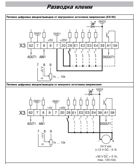
Разводка клемм модуля ввода/вывода Lenze E82ZAFSC.

Быстрый просмотр |
Под заказ Артикул: ESMD751L4TXA Частотный преобразователь ESMD751L4TXA компактного размера, 3 установленных скорости, встроенный EPM модуль памяти настроек.
|
Наши менеджеры обязательно свяжутся с вами и уточнят условия заказа Заказать аналог |

Быстрый просмотр |
Под заказ Артикул: ESMD222X2SFA Частотный преобразователь ESMD222X2SFA компактного размера, 3 установленных скорости, встроенный EPM модуль памяти настроек.
|
Наши менеджеры обязательно свяжутся с вами и уточнят условия заказа Заказать аналог |
|
Быстрый просмотр |
Под заказ Артикул: ESMD371L4TXA Частотный преобразователь ESMD371L4TXA компактного размера, 3 установленных скорости, встроенный EPM модуль памяти настроек.
|
Наши менеджеры обязательно свяжутся с вами и уточнят условия заказа Заказать аналог |
|
Быстрый просмотр |
Под заказ Артикул: ESMD302L4TXA Частотный преобразователь ESMD302L4TXA компактного размера, 3 установленных скорости, встроенный EPM модуль памяти настроек.
|
Наши менеджеры обязательно свяжутся с вами и уточнят условия заказа Заказать аналог |
|
Быстрый просмотр |
Под заказ Артикул: ESMD222L4TXA Частотный преобразователь ESMD222L4TXA компактного размера, 3 установленных скорости, встроенный EPM модуль памяти настроек.
|
Наши менеджеры обязательно свяжутся с вами и уточнят условия заказа Заказать аналог |
|
Быстрый просмотр |
Под заказ Артикул: ESMD251X2SFA Частотный преобразователь ESMD251X2SFA компактного размера, 3 установленных скорости, встроенный EPM модуль памяти настроек.
|
Наши менеджеры обязательно свяжутся с вами и уточнят условия заказа Заказать аналог |

Быстрый просмотр |
Под заказ Артикул: ESMD752L4TXA Частотный преобразователь ESMD752L4TXA компактного размера, 3 установленных скорости, встроенный EPM модуль памяти настроек.
|
Наши менеджеры обязательно свяжутся с вами и уточнят условия заказа Заказать аналог |
|
Быстрый просмотр |
Под заказ Артикул: ESMD112L4TXA Частотный преобразователь ESMD112L4TXA компактного размера, 3 установленных скорости, встроенный EPM модуль памяти настроек.
|
Наши менеджеры обязательно свяжутся с вами и уточнят условия заказа Заказать аналог |

Быстрый просмотр |
Под заказ Артикул: ESV751N02YXB Частотный преобразователь ESV751N02YXB компактного размера, 3 установленных скорости, встроенный EPM модуль памяти настроек.
|
Наши менеджеры обязательно свяжутся с вами и уточнят условия заказа Заказать аналог |
|
Быстрый просмотр |
Под заказ Артикул: ESMD152L4TXA Частотный преобразователь ESMD152L4TXA компактного размера, 3 установленных скорости, встроенный EPM модуль памяти настроек.
|
Наши менеджеры обязательно свяжутся с вами и уточнят условия заказа Заказать аналог |
|
Быстрый просмотр |
Под заказ Артикул: ESMD552L4TXA Частотный преобразователь ESMD552L4TXA компактного размера, 3 установленных скорости, встроенный EPM модуль памяти настроек.
|
Наши менеджеры обязательно свяжутся с вами и уточнят условия заказа Заказать аналог |
|
Быстрый просмотр |
Под заказ Артикул: ESMD551X2SFA Частотный преобразователь ESMD551X2SFA компактного размера, 3 установленных скорости, встроенный EPM модуль памяти настроек.
|
Наши менеджеры обязательно свяжутся с вами и уточнят условия заказа Заказать аналог |
Наличие
…………………………………………………………………………………………………………………………………………………………………………………………………………………………………………………..
13 шт.
Производитель
…………………………………………………………………………………………………………………………………………………………………………………………………………………………………………………..
Lenze
Артикул
…………………………………………………………………………………………………………………………………………………………………………………………………………………………………………………..
E82ZAFSC
Гарантия
…………………………………………………………………………………………………………………………………………………………………………………………………………………………………………………..
12 месяцев
Состояние
…………………………………………………………………………………………………………………………………………………………………………………………………………………………………………………..
Новый
EDS82ZAFPC010
.IFJ
Ä.IFJä
L−force Communication
Communication Manual
PROFIBUS−DP
E82ZAFPC001 / E82ZAFPC010
Function module

Contentsi
1 About this documentation 3 . . . . . . . . . . . . . . . . . . . . . . . . . . . . . . . . . . . . . . . . . . . . . . . . . .
1.1 Document history 4 . . . . . . . . . . . . . . . . . . . . . . . . . . . . . . . . . . . . . . . . . . . . . . . . . . . .
1.2 Conventions used 5 . . . . . . . . . . . . . . . . . . . . . . . . . . . . . . . . . . . . . . . . . . . . . . . . . . . .
1.3 Terminology used 5 . . . . . . . . . . . . . . . . . . . . . . . . . . . . . . . . . . . . . . . . . . . . . . . . . . . .
1.4 Notes used 6 . . . . . . . . . . . . . . . . . . . . . . . . . . . . . . . . . . . . . . . . . . . . . . . . . . . . . . . . . .
2 Safety instructions 7 . . . . . . . . . . . . . . . . . . . . . . . . . . . . . . . . . . . . . . . . . . . . . . . . . . . . . . . . .
2.1 General safety information 7 . . . . . . . . . . . . . . . . . . . . . . . . . . . . . . . . . . . . . . . . . . . .
2.2 Device− and application−specific safety instructions 8 . . . . . . . . . . . . . . . . . . . . . . . .
2.3 Residual hazards 8 . . . . . . . . . . . . . . . . . . . . . . . . . . . . . . . . . . . . . . . . . . . . . . . . . . . . .
3 Product description 9 . . . . . . . . . . . . . . . . . . . . . . . . . . . . . . . . . . . . . . . . . . . . . . . . . . . . . . . .
3.1 Application as directed 9 . . . . . . . . . . . . . . . . . . . . . . . . . . . . . . . . . . . . . . . . . . . . . . .
3.2 Identification 10 . . . . . . . . . . . . . . . . . . . . . . . . . . . . . . . . . . . . . . . . . . . . . . . . . . . . . . . .
3.3 Product features 11 . . . . . . . . . . . . . . . . . . . . . . . . . . . . . . . . . . . . . . . . . . . . . . . . . . . . .
3.4 Connections and interfaces 12 . . . . . . . . . . . . . . . . . . . . . . . . . . . . . . . . . . . . . . . . . . . .
4 Technical data 13 . . . . . . . . . . . . . . . . . . . . . . . . . . . . . . . . . . . . . . . . . . . . . . . . . . . . . . . . . . . .
4.1 General data 13 . . . . . . . . . . . . . . . . . . . . . . . . . . . . . . . . . . . . . . . . . . . . . . . . . . . . . . . .
4.2 Operating conditions 13 . . . . . . . . . . . . . . . . . . . . . . . . . . . . . . . . . . . . . . . . . . . . . . . . .
4.3 Protective insulation 14 . . . . . . . . . . . . . . . . . . . . . . . . . . . . . . . . . . . . . . . . . . . . . . . . . .
4.4 Connection terminals 15 . . . . . . . . . . . . . . . . . . . . . . . . . . . . . . . . . . . . . . . . . . . . . . . . .
4.5 Communication time 16 . . . . . . . . . . . . . . . . . . . . . . . . . . . . . . . . . . . . . . . . . . . . . . . . .
4.6 Dimensions 17 . . . . . . . . . . . . . . . . . . . . . . . . . . . . . . . . . . . . . . . . . . . . . . . . . . . . . . . . . .
5 Installation 18 . . . . . . . . . . . . . . . . . . . . . . . . . . . . . . . . . . . . . . . . . . . . . . . . . . . . . . . . . . . . . . .
5.1 Mechanical installation 18 . . . . . . . . . . . . . . . . . . . . . . . . . . . . . . . . . . . . . . . . . . . . . . . .
5.2 Electrical installation 19 . . . . . . . . . . . . . . . . . . . . . . . . . . . . . . . . . . . . . . . . . . . . . . . . . .
5.2.1 Wiring according to EMC (CE−typical drive system) 19 . . . . . . . . . . . . . . . . .
5.2.2 Wiring with a host (master) 20 . . . . . . . . . . . . . . . . . . . . . . . . . . . . . . . . . . . .
5.2.3 Voltage supply 23 . . . . . . . . . . . . . . . . . . . . . . . . . . . . . . . . . . . . . . . . . . . . . .
5.2.4 Terminal assignment 26 . . . . . . . . . . . . . . . . . . . . . . . . . . . . . . . . . . . . . . . . .
5.2.5 Cable cross−sections and screw−tightening torques 28 . . . . . . . . . . . . . . . . .
5.2.6 Use of plug connectors 29 . . . . . . . . . . . . . . . . . . . . . . . . . . . . . . . . . . . . . . . .
5.3 Bus cable length 30 . . . . . . . . . . . . . . . . . . . . . . . . . . . . . . . . . . . . . . . . . . . . . . . . . . . . . .
2
EDS82ZAFPC010 EN 4.0

Contents i
6 Commissioning 31 . . . . . . . . . . . . . . . . . . . . . . . . . . . . . . . . . . . . . . . . . . . . . . . . . . . . . . . . . . .
6.1 Before switching on 31 . . . . . . . . . . . . . . . . . . . . . . . . . . . . . . . . . . . . . . . . . . . . . . . . . .
6.2 Commissioning steps 32 . . . . . . . . . . . . . . . . . . . . . . . . . . . . . . . . . . . . . . . . . . . . . . . . .
6.3 Configuring the host system (master) 34 . . . . . . . . . . . . . . . . . . . . . . . . . . . . . . . . . . .
6.3.1 Adapting device controls 36 . . . . . . . . . . . . . . . . . . . . . . . . . . . . . . . . . . . . . . .
6.3.2 Defining the user data length 37 . . . . . . . . . . . . . . . . . . . . . . . . . . . . . . . . . . .
6.4 Activating the bus terminating resistor 38 . . . . . . . . . . . . . . . . . . . . . . . . . . . . . . . . . .
6.5 Setting the node address 39 . . . . . . . . . . . . . . . . . . . . . . . . . . . . . . . . . . . . . . . . . . . . .
6.6 Connecting the mains voltage 40 . . . . . . . . . . . . . . . . . . . . . . . . . . . . . . . . . . . . . . . . . .
7 Process data transfer 41 . . . . . . . . . . . . . . . . . . . . . . . . . . . . . . . . . . . . . . . . . . . . . . . . . . . . . . .
7.1 Lenze device control 42 . . . . . . . . . . . . . . . . . . . . . . . . . . . . . . . . . . . . . . . . . . . . . . . . .
7.1.1 Process output data configuration 42 . . . . . . . . . . . . . . . . . . . . . . . . . . . . . .
7.1.2 Process input data configuration 46 . . . . . . . . . . . . . . . . . . . . . . . . . . . . . . .
7.2 DRIVECOM control 49 . . . . . . . . . . . . . . . . . . . . . . . . . . . . . . . . . . . . . . . . . . . . . . . . . . . .
7.2.1 DRIVECOM state machine 49 . . . . . . . . . . . . . . . . . . . . . . . . . . . . . . . . . . . . . .
7.2.2 DRIVECOM control word 50 . . . . . . . . . . . . . . . . . . . . . . . . . . . . . . . . . . . . . . .
7.2.3 DRIVECOM status word 51 . . . . . . . . . . . . . . . . . . . . . . . . . . . . . . . . . . . . . . . .
7.2.4 Bit control commands 52 . . . . . . . . . . . . . . . . . . . . . . . . . . . . . . . . . . . . . . . . .
7.2.5 Status bits 53 . . . . . . . . . . . . . . . . . . . . . . . . . . . . . . . . . . . . . . . . . . . . . . . . . . .
8 Parameter data transfer 54 . . . . . . . . . . . . . . . . . . . . . . . . . . . . . . . . . . . . . . . . . . . . . . . . . . . .
8.1 DRIVECOM parameter data channel 55 . . . . . . . . . . . . . . . . . . . . . . . . . . . . . . . . . . . . .
8.1.1 Addressing of the parameter data 55 . . . . . . . . . . . . . . . . . . . . . . . . . . . . . . .
8.1.2 Addressing of the Lenze parameters 55 . . . . . . . . . . . . . . . . . . . . . . . . . . . . .
8.1.3 Telegram structure 55 . . . . . . . . . . . . . . . . . . . . . . . . . . . . . . . . . . . . . . . . . . . .
8.1.4 Error codes (DRIVECOM) 59 . . . . . . . . . . . . . . . . . . . . . . . . . . . . . . . . . . . . . . .
8.1.5 Reading parameters 60 . . . . . . . . . . . . . . . . . . . . . . . . . . . . . . . . . . . . . . . . . . .
8.1.6 Writing parameters 62 . . . . . . . . . . . . . . . . . . . . . . . . . . . . . . . . . . . . . . . . . . .
8.2 Parameter set transfer 64 . . . . . . . . . . . . . . . . . . . . . . . . . . . . . . . . . . . . . . . . . . . . . . . .
9 Diagnostics 65 . . . . . . . . . . . . . . . . . . . . . . . . . . . . . . . . . . . . . . . . . . . . . . . . . . . . . . . . . . . . . . .
9.1 LED status displays 65 . . . . . . . . . . . . . . . . . . . . . . . . . . . . . . . . . . . . . . . . . . . . . . . . . .
9.2 Troubleshooting and fault elimination 66 . . . . . . . . . . . . . . . . . . . . . . . . . . . . . . . . . . .
10 Codes 67 . . . . . . . . . . . . . . . . . . . . . . . . . . . . . . . . . . . . . . . . . . . . . . . . . . . . . . . . . . . . . . . . . . . .
10.1 Overview 67 . . . . . . . . . . . . . . . . . . . . . . . . . . . . . . . . . . . . . . . . . . . . . . . . . . . . . . . . . . . .
10.2 Communication−relevant Lenze codes 69 . . . . . . . . . . . . . . . . . . . . . . . . . . . . . . . . . . .
10.3 Monitoring codes 73 . . . . . . . . . . . . . . . . . . . . . . . . . . . . . . . . . . . . . . . . . . . . . . . . . . . . .
10.4 Diagnostics codes 75 . . . . . . . . . . . . . . . . . . . . . . . . . . . . . . . . . . . . . . . . . . . . . . . . . . . .
10.5 Important controller codes 82 . . . . . . . . . . . . . . . . . . . . . . . . . . . . . . . . . . . . . . . . . . . . .
EDS82ZAFPC010 EN 4.0
3

Contentsi
11 Appendix 84 . . . . . . . . . . . . . . . . . . . . . . . . . . . . . . . . . . . . . . . . . . . . . . . . . . . . . . . . . . . . . . . .
11.1 Particularities for use in conjunction with Lenze standard devices 84 . . . . . . . . . . . .
11.2 Consistent parameter data 85 . . . . . . . . . . . . . . . . . . . . . . . . . . . . . . . . . . . . . . . . . . . . .
11.3 Parallel operation of AIF and FIF interfaces 87 . . . . . . . . . . . . . . . . . . . . . . . . . . . . . . . .
12 Index 89 . . . . . . . . . . . . . . . . . . . . . . . . . . . . . . . . . . . . . . . . . . . . . . . . . . . . . . . . . . . . . . . . . . . .
4
EDS82ZAFPC010 EN 4.0

0Fig. 0Tab. 0
1 About this documentation
Contents
This documentation exclusively contains descriptions of the function modules
E82ZAFPC001 (PROFIBUS−DP) and E82ZAFPC010 (PROFIBUS−DP PT).
Note!
This documentation supplements the mounting instructions supplied with the
function module and the documentation for the standard devices used.
The mounting instructions contain safety instructions which must be
observed!
ƒ The features and functions of the function module are described in detail.
ƒ Typical applications are explained by means of examples.
ƒ Moreover, this documentation contains the following:
– Safety instructions which must be observed.
– The essential technical data of the function module
– Information on versions of the Lenze standard devices to be used
– Notes on troubleshooting and fault elimination
About this documentation 1
The theoretical concepts are only explained to the level of detail required to understand
the function of the function module.
Depending on the software version of the controller and the version of the »Engineer«
software installed, the screenshots in this documentation may deviate from the
»Engineer« representation.
This documentation does not describe any software provided by other manufacturers. No
liability can be accepted for corresponding data provided in this documentation. For
information on how to use the software, please refer to the host system (master)
documents.
All brand names mentioned in this documentation are trademarks of their respective
owners.
Validity information
The information given in this documentation is valid for the following devices:
Function module Type designation From hardware version From software version
PROFIBUS−DP E82ZAFPC001 3A 10
PROFIBUS−DP PT E82ZAFPC010 3A 10
EDS82ZAFPC010 EN 4.0
5

1
About this documentation
Document history
Target group
This documentation is intended for all persons who plan, install, commission and maintain
the networking and remote service of a machine.
Tip!
Information and auxiliary devices related to the Lenze products can be found
in the download area at
http://www.Lenze.com
1.1 Document history
Material no. Version Description
− 1.0 11/2001 TD06 First edition
− 2.0 06/2004 TD06 Complete revision due to
− 3.0 03/2005 TD06 General revision
.IFJ 4.0 03/2012 TD29 General revision
l Layout change
l New German orthography
l Load capacity of terminal 20
l Structural and editorial adjustments
Your opinion is important to us!
These instructions were created to the best of our knowledge and belief to give you the
best possible support for handling our product.
If you have suggestions for improvement, please e−mail us to:
feedback−docu@Lenze.de
Thank you for your support.
Your Lenze documentation team
6
EDS82ZAFPC010 EN 4.0

1.2 Conventions used
This documentation uses the following conventions to distinguish between different
types of information:
Type of information Identification Examples/notes
Spelling of numbers
Decimal separator
Decimal Standard notation For example: 1234
Hexadecimal 0x[0 … 9, A … F] For example: 0x60F4
Binary
l Nibble
Text
Program name » « PC software
Icons
Page reference Reference to another page with additional
About this documentation
Conventions used
Point In general, the decimal point is used.
For instance: 1234.56
In quotation marks
Point
For example: ´100´
For example: ´0110.0100´
For example: »Engineer«, »Global Drive
Control« (GDC)
information
For instance: 16 = see page 16
1
1.3 Terminology used
Term Meaning
PROFIBUS The term stands for the PROFIBUS−DP variant according to IEC 61158/IEC 61784. A
Standard device
Controller
Frequency inverter
Master PROFIBUS station which takes over the master function in the fieldbus system.
Slave PROFIBUS station which acts as a slave in the fieldbus system.
Code «Container» for one or more parameters which can be used to parameterise or
Subcode If a code contains more than one parameter, these parameters are stored in
POW Process output data word
PIW Process input data word
different PROFIBUS variant is not described in this manual.
Lenze controllers/frequency inverters for which the function module can be used.
11
monitor the controller.
«subcodes».
In this documentation, a slash «/» is used as a separator when specifying a code and
its subcode (e.g. «C00118/3»).
EDS82ZAFPC010 EN 4.0
7

1
1.4 Notes used
About this documentation
Notes used
The following pictographs and signal words are used in this documentation to indicate
dangers and important information:
Safety instructions
Structure of safety instructions:
Danger!
Pictograph and signal word Meaning
Danger!
Danger!
Stop!
Application notes
(characterises the type and severity of danger)
Note
(describes the danger and gives information about how to prevent dangerous
situations)
Danger of personal injury through dangerous electrical voltage.
Reference to an imminent danger that may result in death or
serious personal injury if the corresponding measures are not
taken.
Danger of personal injury through a general source of danger.
Reference to an imminent danger that may result in death or
serious personal injury if the corresponding measures are not
taken.
Danger of property damage.
Reference to a possible danger that may result in property
damage if the corresponding measures are not taken.
Pictograph and signal word Meaning
Note!
Tip!
Important note to ensure troublefree operation
Useful tip for simple handling
Reference to another documentation
8
EDS82ZAFPC010 EN 4.0

2 Safety instructions
Note!
It is absolutely vital that the stated safety measures are implemented in order
to prevent serious injury to persons and damage to material assets.
Always keep this documentation to hand in the vicinity of the product during
operation.
2.1 General safety information
Danger!
Disregarding the following basic safety measures may lead to severe personal
injury and damage to material assets!
Safety instructions
General safety information
2
ƒ Lenze drive and automation components …
… must only be used for the intended purpose.
… must never be operated if damaged.
… must never be subjected to technical modifications.
… must never be operated unless completely assembled.
… must never be operated without the covers/guards.
… can − depending on their degree of protection − have live, movable or rotating parts
during or after operation. Surfaces can be hot.
ƒ All specifications of the corresponding enclosed documentation must be observed.
This is vital for a safe and trouble−free operation and for achieving the specified product
features.
The procedural notes and circuit details provided in this document are proposals which
the user must check for suitability for his application. The manufacturer does not
accept any liability for the suitability of the specified procedures and circuit proposals.
ƒ Only qualified skilled personnel are permitted to work with or on Lenze drive and
automation components.
According to IEC 60364 or CENELEC HD 384, these are persons …
… who are familiar with the installation, assembly, commissioning and operation of
the product,
… possess the appropriate qualifications for their work,
… and are acquainted with and can apply all the accident prevent regulations, directives
and laws applicable at the place of use.
EDS82ZAFPC010 EN 4.0
9

2
2.2 Device− and application−specific safety instructions
Safety instructions
Device− and application−specific safety instructions
ƒ During operation, the function module must be firmly connected to the standard
device.
ƒ With external voltage supply, always use a separate power supply unit, safely
separated to EN 61800−5−1 («SELV»/»PELV»), in every control cabinet.
ƒ Only use cables corresponding to the given specifications ( 24).
Documentation for the standard device, control system, system/machine
All other measures prescribed in this documentation must also be
implemented. Observe the safety instructions and application notes stated in
the documentation.
2.3 Residual hazards
Protection of persons
ƒ If the controllers are used on a phase earthed mains with a rated mains voltage
³ 400 V, protection against accidental contact is not ensured without implementing
external measures. (See chapter «4.3», 16)
Device protection
ƒ The module contains electronic components that can be damaged or destroyed by
electrostatic discharge.
10
EDS82ZAFPC010 EN 4.0

3 Product description
3.1 Application as directed
The E82ZAFPC001 function module …
ƒ is an accessory module for use in conjunction with the following Lenze standard
devices:
Product range Device designation From hardware version
Frequency inverter
Motor starter starttec Vx1x
ƒ is a device intended for use in industrial power systems.
Any other use shall be deemed inappropriate!
Product description
Application as directed
8200 vector
8200 motec Vx14
Vx14
3
The E82ZAFPC010 function module …
ƒ is an accessory module for use in conjunction with the following Lenze standard
devices:
Product range Device designation From hardware version
Frequency inverter 8200 vector Vx14
ƒ is a device intended for use in industrial power systems.
Any other use shall be deemed inappropriate!
EDS82ZAFPC010 EN 4.0
11
3
APPLICATION
010 / 3A22
Product description
Identification
3.2 Identification
APPLICATION
010/ 3A22
Type code E82ZAF P C 0xx 3A 10
Device type
PROFIBUS−DP
Version
Variant
001: Coated design
010: PT design
Hardware version
Software version
L
Type
Id.-No.
Prod.-No.
Ser.-No.
E82AF000P0B201XX
E82ZAFX005
12
EDS82ZAFPC010 EN 4.0

3.3 Product features
ƒ Interface module for the PROFIBUS communication system which can be connected
to the AIF slots of the Lenze 8200 vector, 8200 motec and starttec device series.
ƒ Support of the PROFIBUS−DP−V0 communication profile
ƒ Drive profile:
– DRIVECOM profile «Drive technology 20» (can be switched off)
ƒ Support of I&M0 functionality for standard device identification
ƒ Automatic detection of the baud rate (9.6 kbps … 12 Mbps)
ƒ External 24V supply for maintaining the PROFIBUS network when the standard
device fails
ƒ DIP switch for activating the bus terminating resistor
ƒ LED status displays:
– Voltage supply for function module
– Connection between the function module and the PROFIBUS network
– Connection between the function module and the standard device
Product description
Product features
3
EDS82ZAFPC010 EN 4.0
13
3
Product description
Connections and interfaces
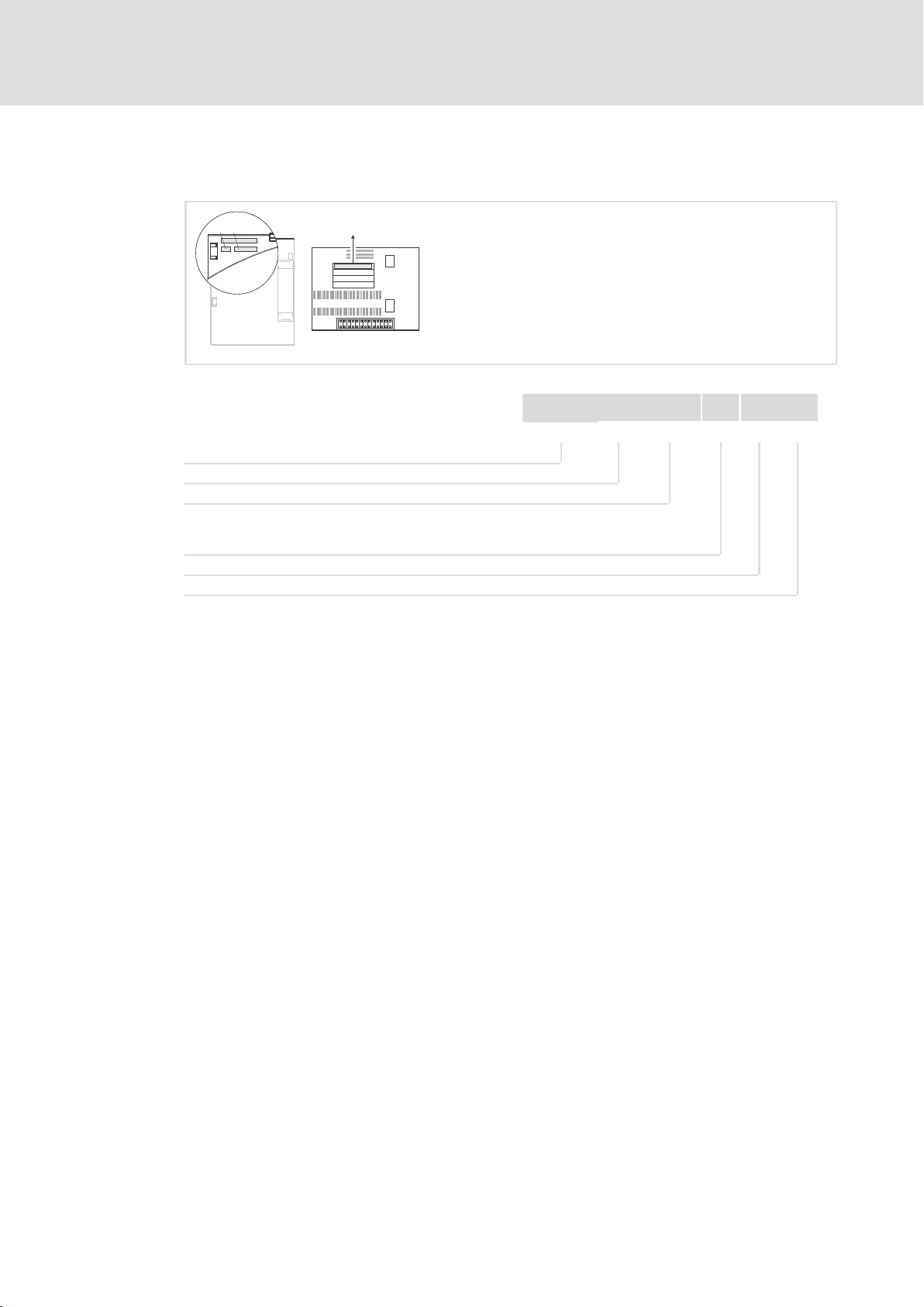
3.4 Connections and interfaces
E82ZAFPC001function module
E82ZAFPC001
0
ON
2
1
AABB
CN
+
VP
7
40 39 28 20 59
3
4
7
E82ZAFP004/AFX009
Pos. Description Detailed
DIP switch for activating the bus terminating resistor 40
Status of PROFIBUS communication (yellow LED)
Connection status to the standard device (green LED)
Terminal strip X3, connection for
l PROFIBUS
l Controller inhibit (CINH)
l External voltage supply
Nameplate 12
information
67
28
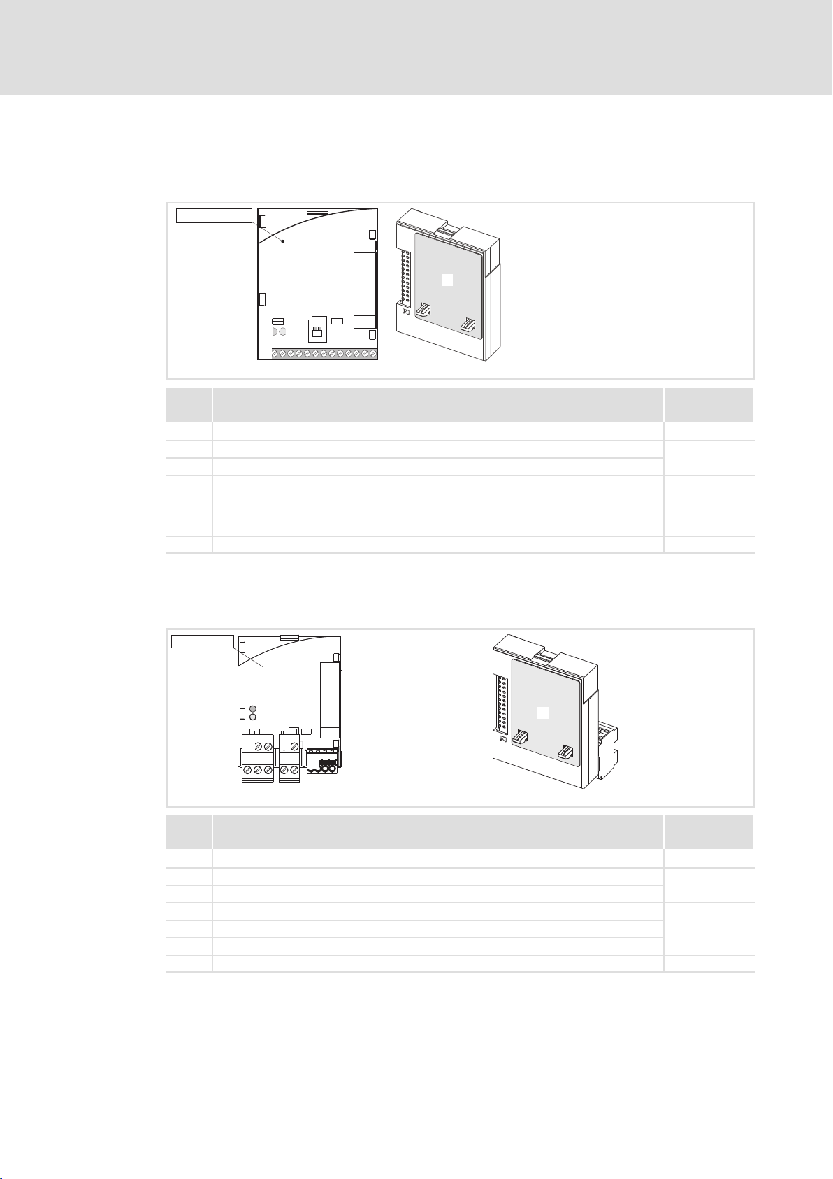
E82ZAFPC010 function module
E82ZAFPC010
3
1
2
0
4
6
5
E82ZAFP012/E82ZAFX015
14
Pos. Description Detailed
DIP switch for activating the bus terminating resistor 40
Status of PROFIBUS communication (yellow LED)
Connection status to the standard device (green LED)
Plug connector X3.1, connection for PROFIBUS
Plug connector X3.2, connection for external voltage supply
Plug connector X3.3, connection for controller inhibit (CINH)
Nameplate 12
information
67
29
EDS82ZAFPC010 EN 4.0

4 Technical data
4.1 General data
Field Values
Order designation E82ZAFPC001 (coated)
PUO ID number 0x00DA
Communication profile
(DIN 19245 Part 1 and Part3)
Communication medium RS485
Drive profile l DRIVECOM profile «Drive technology 20» (can be switched off)
Network topology l Without repeaters: line
PROFIBUS stations Slave
Baud rate [kbps] 9.6 … 12000 (automatic detection)
Process data words 1 … 10 words
DP user data length 1 … 10 process data words +
Max. number of bus devices l Standard: 32 (= 1 bus segment)
Max. cable length per bus
segment
External DC−voltage supply +24 V DC ±10 %, max. 80 mA
Technical data
General data
E82ZAFPC010 (PT design)
l PROFIBUS−DP−V0
l With repeaters: line or tree
(16 bits/word)
4 parameter data words
l With repeaters: 125
1200 m (depending on the baud rate and cable type used)
4
4.2 Operating conditions
Ambient conditions
Climate
Storage
Transport IEC/EN 60721−3−2 2K3 (−25 to +70 °C)
Operation Corresponding to the data of the Lenze standard device used (see documentation
Pollution EN 61800−5−1 Degree of pollution 2
Degree of protection IP20 (protection against accidental contact according to NEMA 250 type 1)
IEC/EN 60721−3−1 1K3 (−25 to +60 °C)
of the standard device).
EDS82ZAFPC010 EN 4.0
15

4
Technical data
Protective insulation
4.3 Protective insulation
Danger!
Dangerous electrical voltage
If Lenze controllers are used on a phase earthed mains with a rated mains
voltage ³ 400 V, protection against accidental contact is not ensured without
implementing external measures.
Possible consequences:
ƒ Death or serious injury
Protective measures:
ƒ If protection against accidental contact is required for the control terminals
of the controller and the connections of the plugged device modules, …
– a double isolating distance must exist.
– the components to be connected must be provided with the second
E82ZAFPC001function module
Protective insulation between bus and … Type of insulation (according to EN 61800−5−1)
l Power section
– 8200 vector Reinforced insulation
– 8200 motec Reinforced insulation
– starttec Reinforced insulation
l Reference earth / PE (X3/7) Functional insulation
l External supply (X3/59) Functional insulation
l Terminal X3/20 Functional insulation
l Terminal X3/28 Functional insulation
isolating distance.
E82ZAFPC010 function module
Insulation between bus and … Type of insulation (in accordance with EN 61800−5−1)
l 8200 vector power stage Reinforced insulation
l Reference earth / PE (X3.2/7, X3.3/7) Functional insulation
l External supply (X3.2/59) Functional insulation
l Supply for CINH (X3.3/20) Functional insulation
l Controller inhibit, CINH (X3.3/28) Functional insulation
16
EDS82ZAFPC010 EN 4.0

Technical data
Connection terminals
4
4.4 Connection terminals
E82ZAFPC001function module
Terminal strip X3/
VP Level: 5 V (reference: GND3)
28 External supply of terminal with
20 DC voltage source for internal supply of controller inhibit (CINH)
59 External supply of function module with
E82ZAFPC010 function module
Terminal strip X3.2/
59
Terminal strip X3.3/
28 External supply of terminal with
20
Load capacity: I
U(ext.) = +12 V DC − 0% … +30 V DC + 0%
U = + 20 V (reference: GND1),
= 20 mA
I
max
U(ext.) = +24 V DC ± 10%
External supply of function module with
U(ext.) = +24 V DC ± 10%
U(ext.) = +12 V DC − 0% … +30 V DC + 0%
DC voltage source for internal supply of controller inhibit (CINH)
U = + 20 V (reference: GND1)
Load capacity: I
max
max
= 10 mA
= 20 mA
EDS82ZAFPC010 EN 4.0
17

4
Technical data
Communication time
4.5 Communication time
The communication time is the time between the start of a request and the arrival of the
corresponding response.
The communication times depend on …
ƒ the processing time in the controller
ƒ the transmission delay time
– the baud rate
– the telegram length
Processing time 8200vector / 8200motec / starttec
There are no interdependencies between parameter data and process data.
ƒ Parameter data: approx. 30 ms + 20 ms tolerance
ƒ Process data: approx. 3 ms + 2 ms tolerance
18
EDS82ZAFPC010 EN 4.0
Technical data
Dimensions
4
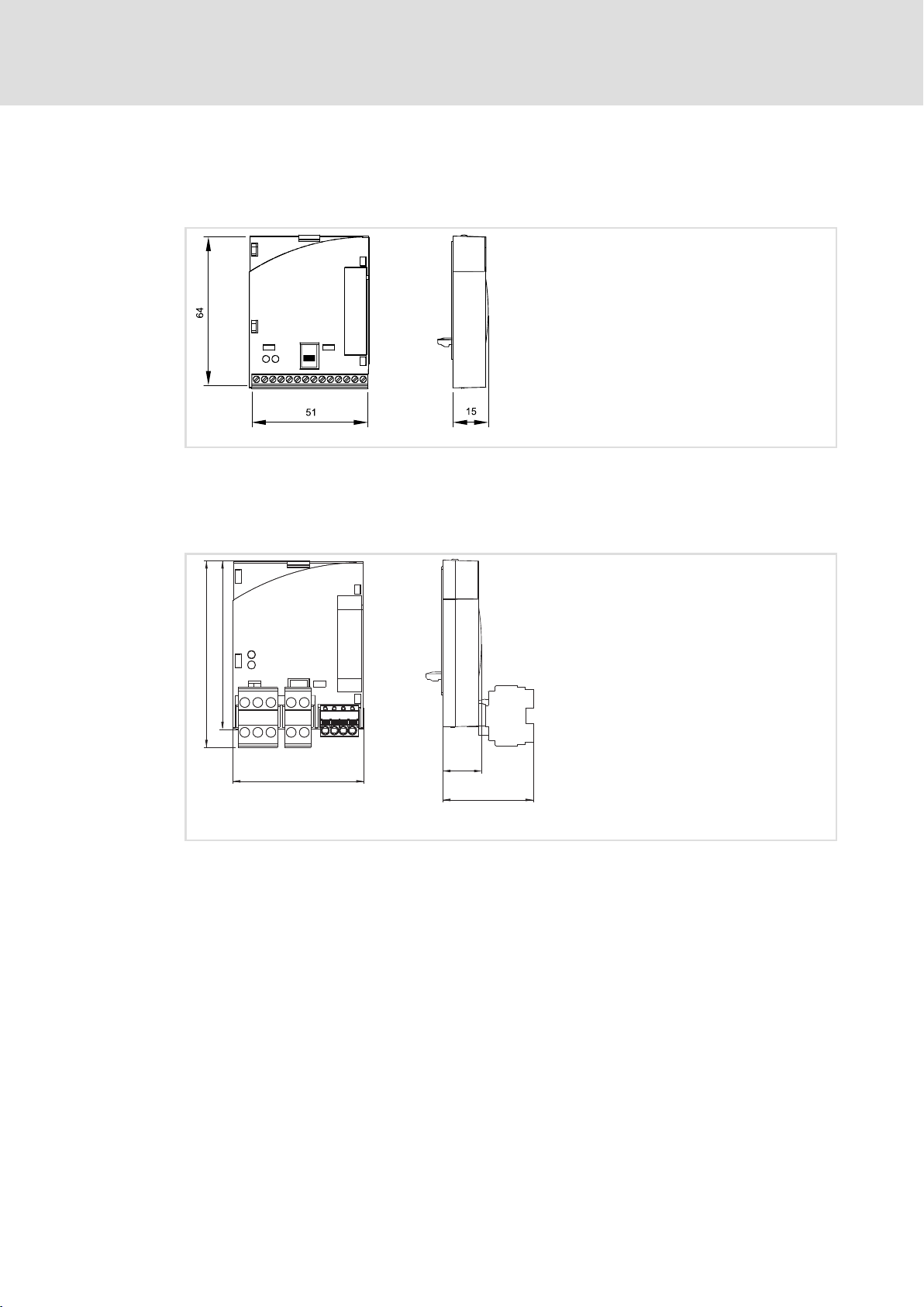
4.6 Dimensions
E82ZAFPC001function module
E82ZAFPC010 function module
E82ZAFL011B
All dimensions in mm
72
64
51
All dimensions in mm
15
30
E82ZAFP007
EDS82ZAFPC010 EN 4.0
19

5
Installation
Mechanical installation
5 Installation
Danger!
Inappropriate handling of the function module and the standard device can
cause serious injuries to persons and damage to material assets.
Observe the safety instructions and residual hazards included in the
documentation of the standard device.
Stop!
The device contains components that can be destroyed by electrostatic
discharge!
Before working on the device, the personnel must ensure that they are free of
electrostatic charge by using appropriate measures.
5.1 Mechanical installation
Follow the notes given in the Mounting Instructions for the standard device for the
mechanical installation of the function module.
The Mounting Instructions for the standard device …
ƒ are part of the scope of supply and are enclosed with each device.
ƒ provide tips to avoid damage provide tips to avoid damage through improper
handling.
ƒ describe the obligatory order of installation steps.
20
EDS82ZAFPC010 EN 4.0

Wiring according to EMC (CE−typical drive system)
5.2 Electrical installation
5.2.1 Wiring according to EMC (CE−typical drive system)
For wiring according to EMC requirements observe the following points:
Note!
ƒ Separate control cables/data lines from motor cables.
ƒ Connect the shields of control cables/data lines at both ends in the case of
digital signals.
ƒ Use an equalizing conductor with a cross−section of at least 16mm
(reference:PE) to avoid potential differences between the bus nodes.
ƒ Observe the other notes concerning EMC−compliant wiring given in the
documentation for the standard device.
Wiring procedure
Installation
Electrical installation
5
2
1. Observe the bus topology, do not use any stubs.
2. Observe the notes and wiring instructions given in the documents for the control
system.
3. Only use cables corresponding to the listed specifications ( 24).
4. Observe the notes for the voltage supply of the module ( 25).
5. Activate the bus terminating resistors on the first and last physical bus device
( 40).
EDS82ZAFPC010 EN 4.0
21
5
Installation
Electrical installation
Wiring with a host (master)
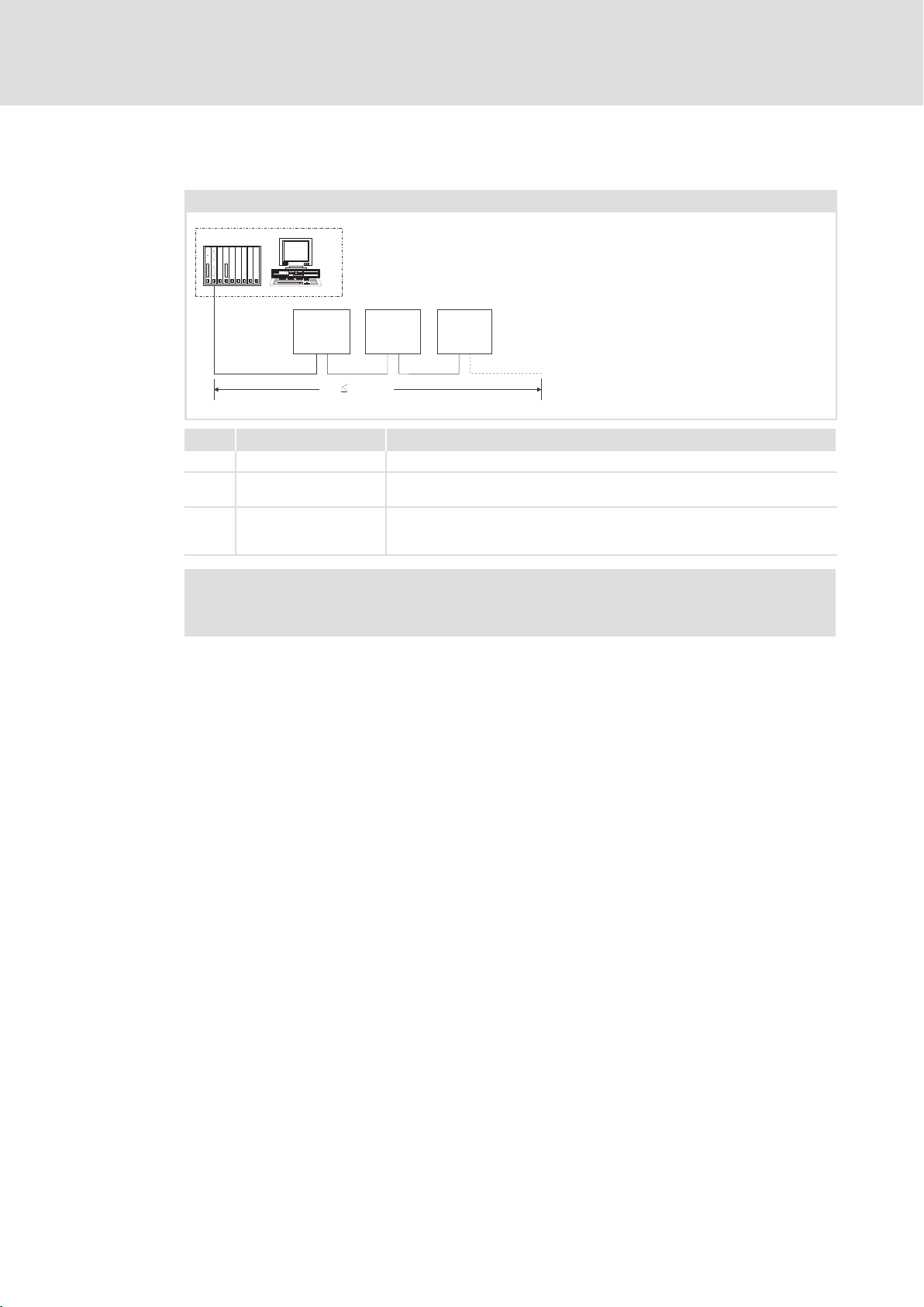
5.2.2 Wiring with a host (master)
Basic design of a PROFIBUS network with RS485 cabling without repeater
1
333
starttec
8200 vector
8200 motec
+
E82ZAFPC0xx
222
No. Element Note
1 Host E.g. PC or PLC with PROFIBUS master interface module
2 Bus cable Connects the PROFIBUS master interface module to the function modules.
3 PROFIBUS slave Applicable standard device ( 11)with function module
1200 m
0m
8200 vector
8200 motec
E82ZAFPC0xx
starttec
+
l The baud rate depends on the length of the bus cable ( 24).
l Activate bus terminating resistors at the first and last physical node
starttec
8200 vector
8200 motec
+
E82ZAFPC0xx
( 40).
E82ZAFP005
Note!
When using a repeater, max. 125 nodes can communicate via the PROFIBUS.
22
EDS82ZAFPC010 EN 4.0
Installation
Electrical installation
Wiring with a host (master)
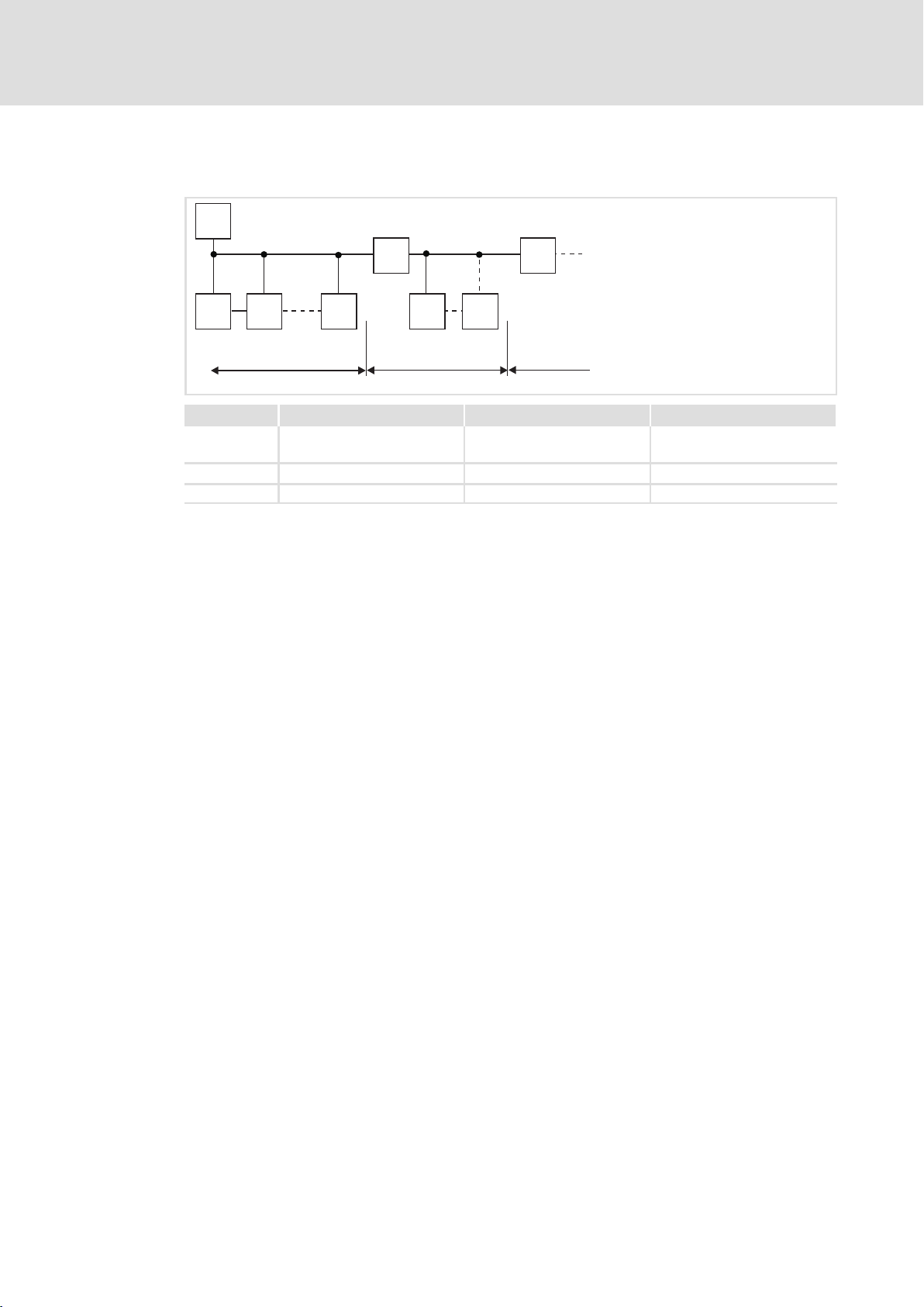
Number of bus devices
M
RR
SS S S S
123
Segment Master (M) Slave (S) Repeater (R)
11231
30
2 − 30 1
3 − 30 1
−
−
5
2133PFB004
Tip!
Repeaters do not have a device address. When calculating the maximum
number of bus devices, they reduce the number of devices by 1 on each side of
the segment.
Repeaters can be used to build up line and tree topologies. The maximum total
bus system expansion depends on …
ƒ the baud rate used;
ƒ the number of repeaters used.
EDS82ZAFPC010 EN 4.0
23

5
Installation
Electrical installation
Wiring with a host (master)
Specification of the transmission cable
Note!
Only use cables complying with the listed specifications of the PROFIBUS user
organisation.
Field Values
Specific resistance 135 … 165 W/km, (f = 3 … 20 MHz)
Capacitance per unit length £ 30 nF/km
Loop resistance < 110 W/km
Core diameter > 0.64 mm
Core cross−section > 0.34 mm
Cores Twisted double, insulated and shielded
2
Bus cable length
The length of the bus cable depends on the baud rate used:
Baud rate [kbps] Length [m]
9.6 … 93.75 1200
187.5 1000
500 400
1500 200
3000 … 12000 100
Note!
The baud rate depending on the data volume, cycle time, and number of nodes
should only be selected as high as required for the application.
Tip!
For high baud rates we recommend to consider the use of optical fibres.
Advantages of optical fibres:
ƒ On the transmission path external electromagnetic interference remains
ineffective.
ƒ Bus lengths of several kilometres are also possible with higher baud rates.
The bus length
– is irrespective of the baud rate.
– depends on the optical fibre used.
24
EDS82ZAFPC010 EN 4.0
Installation
Electrical installation
Voltage supply
5
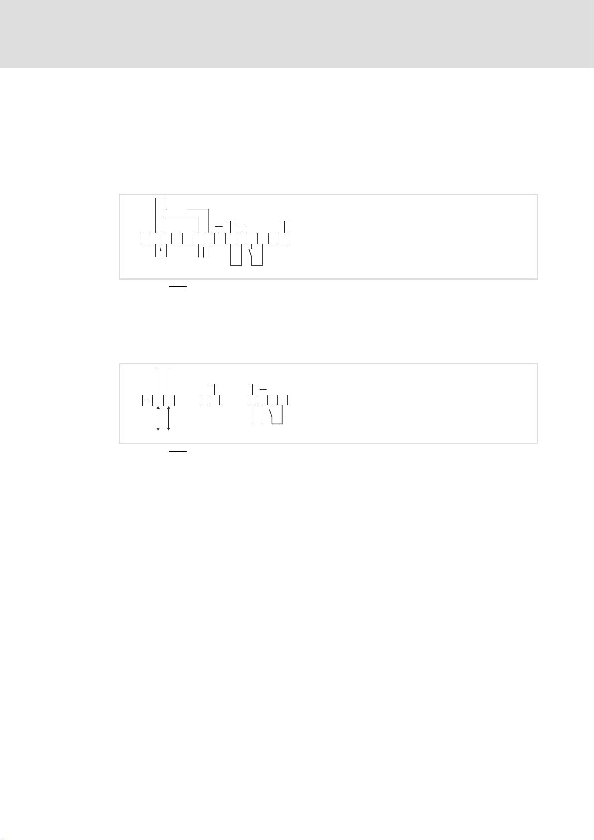
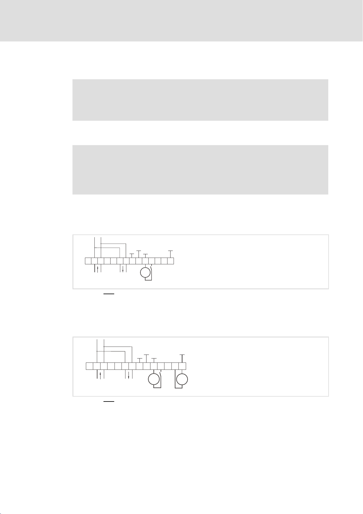
5.2.3 Voltage supply
Internal DC voltage supply
E82ZAFPC001function module
The internal voltage is provided at terminal X3/20. It serves to supply the controller inhibit
(CINH).
+5V
B
AVP
+
X3
T/R(A) T/R(B) T/R(A) T/R(B)
CN
E82ZAFPC010 function module
The internal voltage is provided at terminal X3.3/20. It serves to supply the controller
inhibit (CINH).
T/R(A) T/R(B)
A
X3.1 X3.2
B
GND1
+20V
7
20 59
2839
BA
GND3
40
GND1
7
GND2
The min. wiring requirements for operation
GND1
720
59
X3.3
GND1
GND2
+20V
28397
E82ZAFP001
T/R(A) T/R(B)
E82ZAFP011
The min. wiring requirements for operation
EDS82ZAFPC010 EN 4.0
25
5
Installation
Electrical installation
Voltage supply
External voltage supply
Note!
Always use a separate power supply unit in every control cabinet and safely
separate it according to EN 61800−5−1 («SELV»/»PELV») in the case of external
voltage supply and larger distances between the control cabinets.
External voltage supply of the function module is required if communication via the
fieldbus is to be maintained even when the power supply of the standard device fails.
Note!
With external voltage supply of the function module, the active bus
terminating resistor is fed independently of the operation of the standard
device. In this way, the bus system remains active even when the standard
device is switched off or fails.
E82ZAFPC001function module
External voltage supply with one voltage source for
ƒ X3/28 (controller inhibit (CINH))
GND1
+20V
7
20 59
2839
B
AVP
X3
+
CN
T/R(A) T/R(B) T/R(A) T/R(B)
GND1
GND3
+5V
GND2
7
BA
40
_
+
The min. wiring requirements for operation
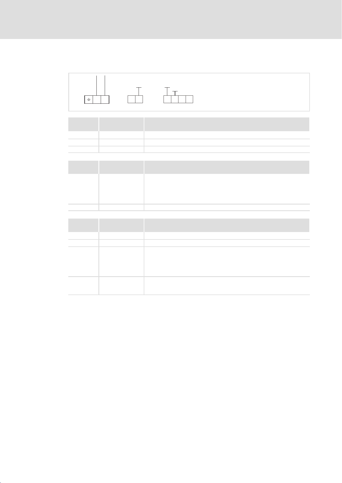
External voltage supply with two voltage sources for
1. X3/28 (controller inhibit (CINH))
2. X3/59 (function module)
+20V
GND1
720
59
_
X3
GND1
GND2
+5V
A
+
VP
B
CN
GND3
40
BA
28397
_
E82ZAFP002
26
T/R(A) T/R(B) T/R(A) T/R(B)
The min. wiring requirements for operation
+
+
E82ZAFP003
EDS82ZAFPC010 EN 4.0

E82ZAFPC010 function module
External voltage supply with one voltage source for
ƒ X3.3/28 (controller inhibit (CINH))
T/R(A) T/R(B)
A
X3.1 X3.2
B
GND1
720
59
X3.3
GND1
GND2
_
+20V
28397
Installation
Electrical installation
Voltage supply
5
T/R(A) T/R(B)
+
The min. wiring requirements for operation
External voltage supply with two voltage sources for
1. X3.3/28 (controller inhibit (CINH))
2. X3.2/59 (function module)
T/R(A) T/R(B)
A
X3.1 X3.2
T/R(A) T/R(B)
B
GND1
720
59
The min. wiring requirements for operation
GND1
GND2
+20V
X3.3
_
+
28397
_
+
E82ZAFP012
E82ZAFP013
EDS82ZAFPC010 EN 4.0
27

5
Installation
Electrical installation
Terminal assignment
5.2.4 Terminal assignment
E82ZAFPC001function module
B
AVP
CN
Designation Function / level
PES Additional HF−shield termination
+
X3
Terminal
X3/
A T/R(A) RS485 data line A
B T/R(B) RS485 data line B
CN CNTR For function see PROFIBUS standard *)
VP For function see PROFIBUS standard *)
40 GND3 Reference potential for PROFIBUS network *)
7 GND1 Reference potential for X3/20
39 GND2 Reference potential for controller inhibit (CINH) at X3/28
28 CINH Controller inhibit
20 DC voltage source for internal supply of controller inhibit (CINH)
59 External DC voltage supply for the function module
*) E.g. for repeater connection
+5V
+20V
20 59
GND1
7
E82ZAFP001
GND1
GND3
GND2
7
BA
40
2839
l Level during data transmission: CNTR = HIGH
(+5 V DC, reference:GND3)
l U = +5 V DC (reference:GND3)
l I
= 10 mA
max
l Start = HIGH (+12 … +30 V DC)
l Stop = LOW (0 … +3 V DC)
(reference: GND2)
l +20 V DC (reference: GND1)
l I
= 20 mA
max
l +24VDC±10% (reference: GND1)
l Current consumption on 24 V DC: 80 mA
The current for looping through the supply voltage to other nodes via
terminal 59 must be max. 3A.
28
EDS82ZAFPC010 EN 4.0
E82ZAFPC010 function module
T/R(A) T/R(B)
GND1
720
A
X3.1 X3.2
B
59
X3.3
GND1
GND2
Installation
5
Electrical installation
Terminal assignment
+20V
28397
E82ZAFP011
Terminal
X3.1/
A T/R(A) RS485 data line A
B T/R(B) RS485 data line B
Terminal
X3.2/
59 External DC voltage supply for the function module
7 GND1 Reference potential for X3.3/20
Terminal
X3.3/
7 GND1 Reference potential for X3.3/20
39 GND2 Reference potential for controller inhibit (CINH) at X3.3/28
28 CINH Controller inhibit
20 DC voltage source for external supply of controller inhibit (CINH)
Designation Function / level
PES Additional HF shield termination
Designation Function / level
l +24VDC±10% (reference: GND1)
l Current consumption on 24 V DC: 80 mA
The current for looping through the supply voltage to other nodes via
terminal 59 must be max. 3A.
Designation Function / level
l Input resistance: 3.3 kW
l Start = HIGH (+12 … +30 V)
l Stop = LOW (0 … +3 V)
(reference: GND2)
l +20 V (reference: GND1)
l I
= 10 mA
max
EDS82ZAFPC010 EN 4.0
29
Loading…
FAQ: Types of Manuals and Their Contents
Lenze E82ZAFSC Manuals come in various types, each serving a specific purpose to help users effectively operate and maintain their devices. Here are the common types of Lenze E82ZAFSC User Guides and the information they typically include:
- User Manuals: Provide comprehensive instructions on how to use the device, including setup, features, and operation. They often include troubleshooting tips, safety information, and maintenance guidelines.
- Service Instructions: Designed for technicians and repair professionals, these manuals offer detailed information on diagnosing and repairing issues with the device. They include schematics, parts lists, and step-by-step repair procedures.
- Installation Guides: Focus on the installation process of the device, providing detailed instructions and diagrams for proper setup. They are essential for ensuring the device is installed correctly and safely.
- Maintenance Manuals: Provide guidance on routine maintenance tasks to keep the device in optimal condition. They cover cleaning procedures, part replacements, and regular servicing tips.
- Quick Start Guides: Offer a concise overview of the essential steps needed to get the device up and running quickly. They are ideal for users who need immediate assistance with basic setup and operation.
Each type of Lenze E82ZAFSC instruction is designed to address specific needs, ensuring users have the necessary information to use, maintain, and repair their devices effectively.
Related Instructions for Lenze E82ZAFSC:
1
8200 vector series
250
1405
239
2
L-force EWS
12
1285
193
5
POWERLINK E84DGFCL Series
Communications manual Lenze DC Drives Communications manual (File: lenze-powerlink-e84dgfcl-series-communications-manual-70, 14/11/2024)
70
291
73
6
EPM-H312
Operating instructions manual Lenze Control Unit Operating instructions manual (File: lenze-epm-h312-operating-instructions-manual-94, 28/10/2024)
94
177
43
8
i700
Reference manual Lenze i700 User Manual (Reference manual), @78HA3I
359
498
110
10
i950 Series
184
1106
222
Control Unit Devices by Other Brands:
|
Burkert EPS 16 ATEX 1072 X Operating Instructions Manual Burkert Servo Drives Operating instructions manual (File: burkert-eps-16-atex-1072-x-operating-instructions-manual-22, 25/01/2025) Operating Instructions 25 Jan 2025 | 22 |
|
|
Savant Pro Host Deployment Manual #VK41BF: Pro Host Controller Deployment manual Savant Super Pro Host Deployment Guide 15 Dec 2024 | 12 |
|
|
IPS I0633SU0020PA-USB Quick Start Manual IPS I0633SU0020PA-USB Guide (Quick start manual), @5GMF23 Innovative Photonic Solutions 313 Enterprise Drive Plainsboro, NJ 08536 14 May 2025 | 11 |
|
|
Pentair Anderson Greenwood 93 Series Installation And Maintenance Instructions Manual Control Unit #W8C284 Anderson Greenwood Series 93 Positive Pressure POSRV 18 Jan 2025 | 10 |
Categories:
Monitor
Inverter Drive
Gateway
TV Mount
Spring Applied Brakes
Racks & Stands