
DVD/CD RECEIVER
SERVICE MANUAL
MODEL: LH-T6745
LH-T6745D
LHS-T6745C, LHS-T6745W, LHS-T6745T
SERVICE MANUAL LH-T6745 (LH-T6745D LHS-T6745C, LHS-T6745W, LHS-T6745T)

— 1-1 —
[CONTENTS]
❍ SECTION 1.GENERAL
• SERVICING PRECAUTIONS . . . . . . . . . . . . . . . . . . . . . . . . . . . . . . . . . . . . . . . . . . . . . . . 1-2
• ESD PRECAUTIONS . . . . . . . . . . . . . . . . . . . . . . . . . . . . . . . . . . . . . . . . . . . . . . . . . . . . . 1-4
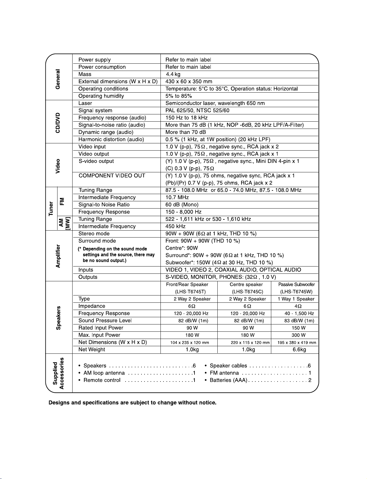
• SPECIFICATIONS . . . . . . . . . . . . . . . . . . . . . . . . . . . . . . . . . . . . . . . . . . . . . . . . . . . . . . . .1-5
❍ SECTION 2. AUDIO PART
• ELECTRICAL TROUBLESHOOTING GUIDE . . . . . . . . . . . . . . . . . . . . . . . . . . . . . . . . . . . . 2-1
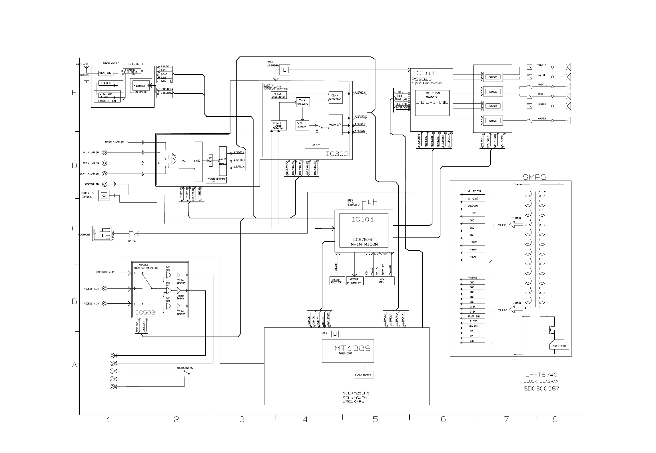
• BLOCK DIAGRAM . . . . . . . . . . . . . . . . . . . . . . . . . . . . . . . . . . . . . . . . . . . . . . . . . . . . . . . . 2-5
• SCHEMATIC DIAGRAMS . . . . . . . . . . . . . . . . . . . . . . . . . . . . . . . . . . . . . . . . . . . . . . . . . . 2-7
• WIRNG DIAGRAMS . . . . . . . . . . . . . . . . . . . . . . . . . . . . . . . . . . . . . . . . . . . . . . . . . . . . . 2-21
• PRINTED CIRCUIT DIARGAMS . . . . . . . . . . . . . . . . . . . . . . . . . . . . . . . . . . . . . . . . . . . . 2-23
❍ SECTION 3.DVD PART
• DVD PART ELECTRICAL TROUBLESHOOTING GUIDE . . . . . . . . . . . . . . . . . . . . . . . . . . . .3-1
• DETAILS AND WAVEFORMS ON SYSTEM TEST AND DEBUGGING . . . . . . . . . . . . . . . . .3-8
• BLOCK DIAGRAM . . . . . . . . . . . . . . . . . . . . . . . . . . . . . . . . . . . . . . . . . . . . . . . . . . . . . . . 3-21
• DVD PART SCHEMATIC DIAGRAMS . . . . . . . . . . . . . . . . . . . . . . . . . . . . . . . . . . . . . . . . .3-25
❍ SECTION 4. EXPLODED VIEWS . . . . . . . . . . . . . . . . . . . . . . . . . . . . . . . . . . .4-1
❍ SECTION 5. SPEAKER PART . . . . . . . . . . . . . . . . . . . . . . . . . . . . . . . . . . . . .5-1
❍ SECTION 6. REPLACEMENT PARTS LIST . . . . . . . . . . . . . . . . . . . . . . . . . . .6-1
— 1-2 —
SECTION 1. GENERAL
❏ SERVICING PRECAUTIONS
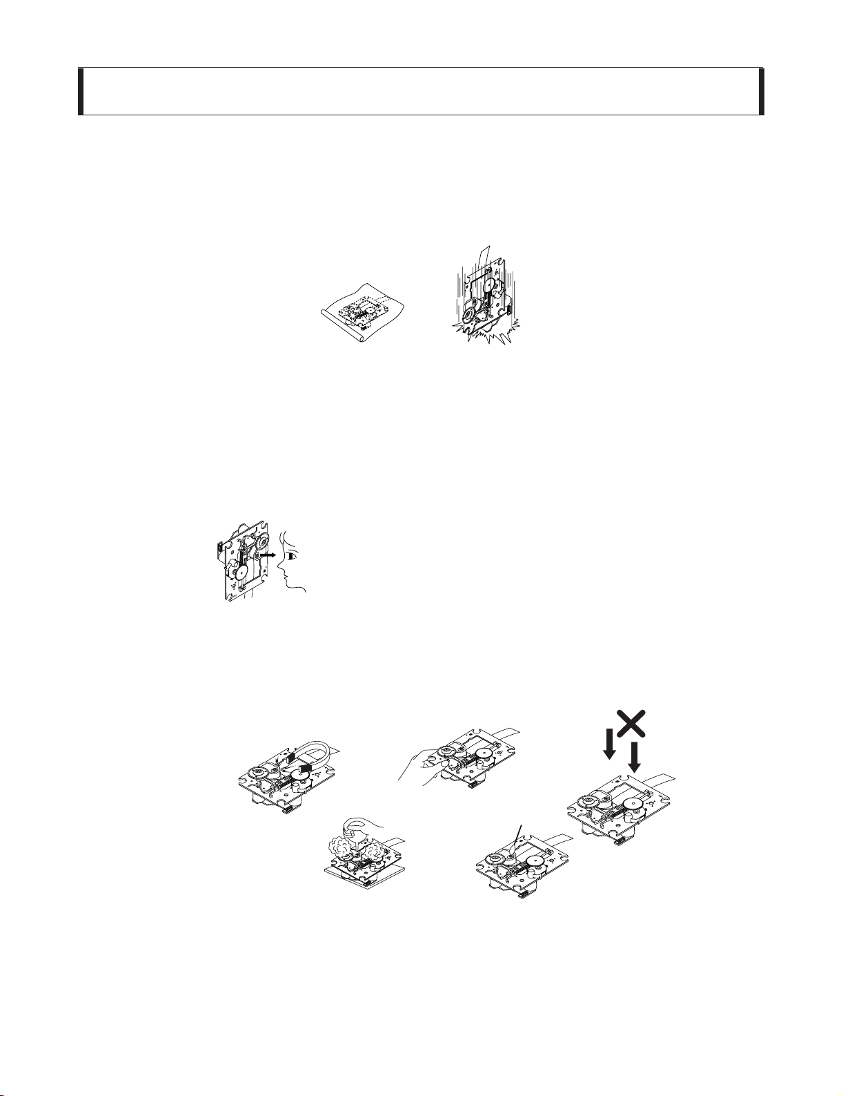
NOTES REGARDING HANDLING OF THE PICK-UP
1. Notes for transport and storage
1) The pick-up should always be left in its conductive bag until immediately prior to use.
2) The pick-up should never be subjected to external pressure or impact.
2. Repair notes
1) The pick-up incorporates a strong magnet, and so should never be brought close to magnetic materials.
2) The pick-up should always be handled correctly and carefully, taking care to avoid external pressure and
impact. If it is subjected to strong pressure or impact, the result may be an operational malfunction and/or
damage to the printed-circuit board.
3) Each and every pick-up is already individually adjusted to a high degree of precision, and for that reason
the adjustment point and installation screws should absolutely never be touched.
4) Laser beams may damage the eyes!
Absolutely never permit laser beams to enter the eyes!
Also NEVER switch ON the power to the laser output part (lens, etc.) of the pick-up if it is damaged.
5) Cleaning the lens surface
If there is dust on the lens surface, the dust should be cleaned away by using an air bush (such as used
for camera lens). The lens is held by a delicate spring. When cleaning the lens surface, therefore, a cotton
swab should be used, taking care not to distort this.
6) Never attempt to disassemble the pick-up.
Spring by excess pressure. If the lens is extremely dirty, apply isopropyl alcohol to the cotton swab.
(Do not use any other liquid cleaners, because they will damage the lens.) Take care not to use too much
of this alcohol on the swab, and do not allow the alcohol to get inside the pick-up.
Storage in conductive bag
Drop impact
NEVER look directly at the laser beam, and don’t let
contact fingers or other exposed skin.
Magnet
How to hold the pick-up
Conductive Sheet
Cotton swab
Pressure
Pressure
— 1-3 —
NOTES REGARDING COMPACT DISC PLAYER REPAIRS
1. Preparations
1) Compact disc players incorporate a great many ICs as well as the pick-up (laser diode). These components
are sensitive to, and easily affected by, static electricity. If such static electricity is high voltage, components
can be damaged, and for that reason components should be handled with care.
2) The pick-up is composed of many optical components and other high-precision components. Care must be
taken, therefore, to avoid repair or storage where the temperature of humidity is high, where strong magnetism is present, or where there is excessive dust.
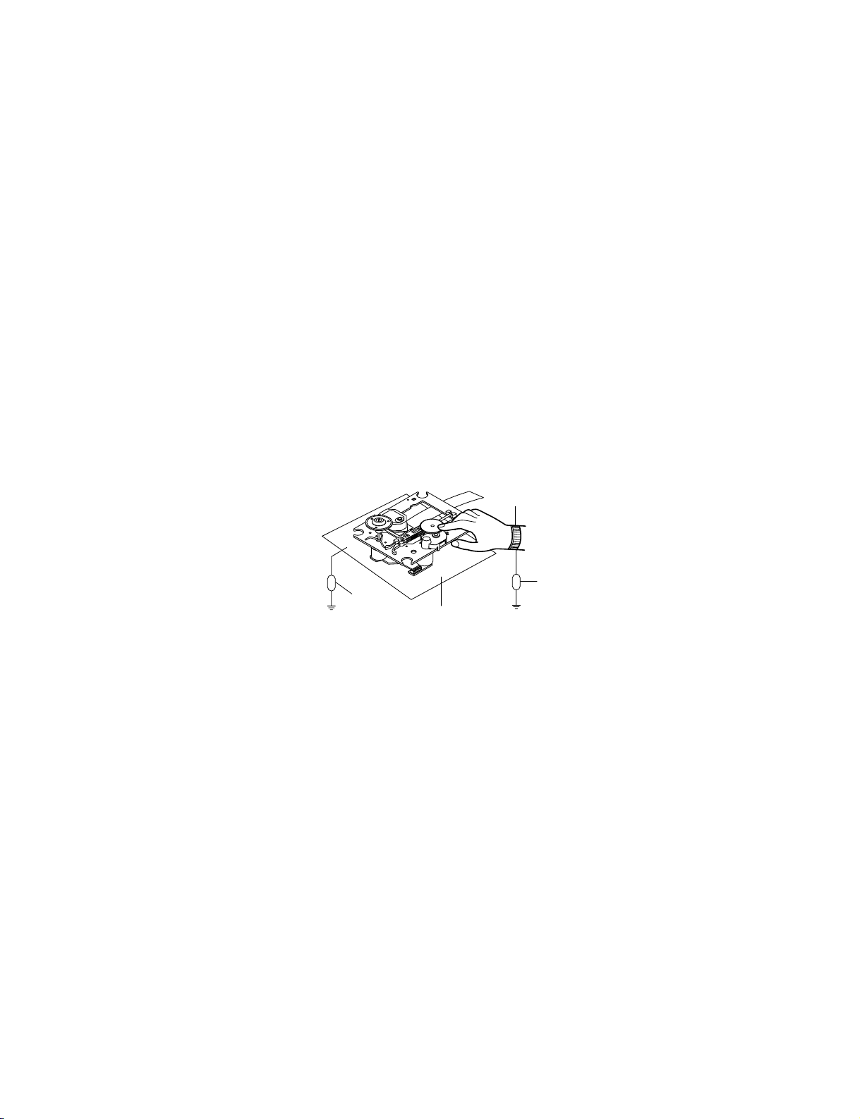
2. Notes for repair
1) Before replacing a component part, first disconnect the power supply lead wire from the unit
2) All equipment, measuring instruments and tools must be grounded.
3) The workbench should be covered with a conductive sheet and grounded.
When removing the laser pick-up from its conductive bag, do not place the pick-up on the bag. (This is
because there is the possibility of damage by static electricity.)
4) To prevent AC leakage, the metal part of the soldering iron should be grounded.
5) Workers should be grounded by an armband (1M Ω)
6) Care should be taken not to permit the laser pick-up to come in contact with clothing, in order to prevent static electricity changes in the clothing to escape from the armband.
7) The laser beam from the pick-up should NEVER be directly facing the eyes or bare skin.
Resistor
(1 Mohm)
Conductive
Sheet
Resistor
(1 Mohm)
Armband
— 1-4 —
❏ ESD PRECAUTIONS
Electrostatically Sensitive Devices (ESD)
Some semiconductor (solid state) devices can be damaged easily by static electricity. Such components
commonly are called Electrostatically Sensitive Devices (ESD). Examples of typical ESD devices are integrated
circuits and some field-effect transistors and semiconductor chip components. The following techniques should
be used to help reduce the incidence of component damage caused by static electricity.
1. Immediately before handling any semiconductor component or semiconductor-equipped assembly, drain off
any electrostatic charge on your body by touching a known earth ground. Alternatively, obtain and wear a
commercially available discharging wrist strap device, which should be removed for potential shock reasons
prior to applying power to the unit under test.
2. After removing an electrical assembly equipped with ESD devices, place the assembly on a conductive sur-
face such as aluminum foil, to prevent electrostatic charge buildup or exposure of the assembly.
3. Use only a grounded-tip soldering iron to solder or unsolder ESD devices.
4. Use only an anti-static solder removal device. Some solder removal devices not classified as «anti-static» can
generate electrical charges sufficient to damage ESD devices.
5. Do not use freon-propelled chemicals. These can generate electrical charges sufficient to damage ESD
devices.
6. Do not remove a replacement ESD device from its protective package until immediately before you are
ready to install it. (Most replacement ESD devices are packaged with leads electrically shorted together by
conductive foam, aluminum foil or comparable conductive materials).
7. Immediately before removing the protective material from the leads of a replacement ESD device, touch the
protective material to the chassis or circuit assembly into which the device will by installed.
CAUTION : BE SURE NO POWER IS APPLIED TO THE CHASSIS OR CIRCUIT, AND OBSERVE ALL
OTHER SAFETY PRECAUTIONS.
8. Minimize bodily motions when handing unpackaged replacement ESD devices. (Otherwise harmless motion
such as the brushing together of your clothes fabric or the lifting of your foot from a carpeted floor can generate static electricity sufficient to damage an ESD device).
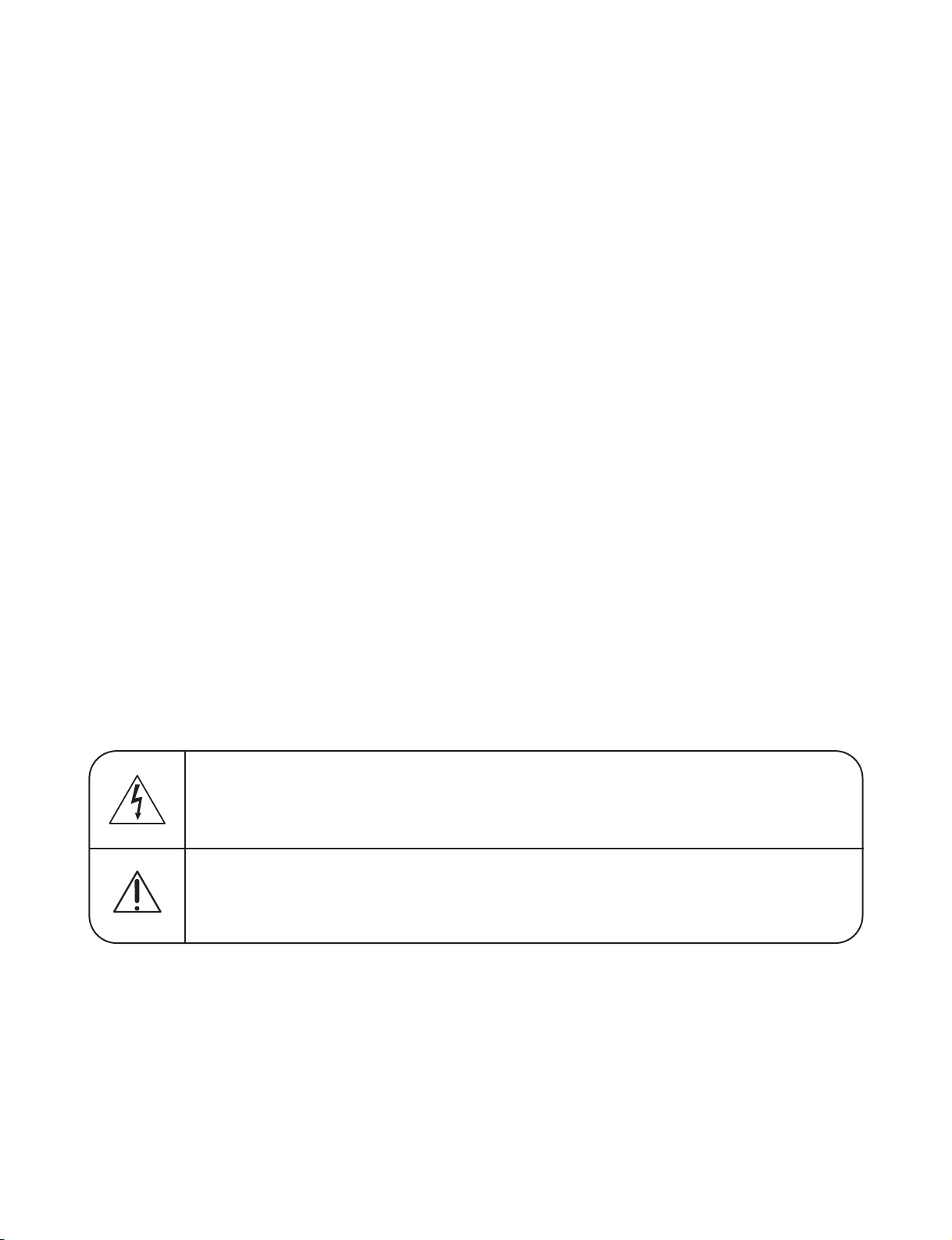
CAUTION. GRAPHIC SYMBOLS
THE LIGHTNING FLASH WITH APROWHEAD SYMBOL. WITHIN AN EQUILATERAL TRIANGLE, IS
INTENDED TO ALERT THE SERVICE PERSONNEL TO THE PRESENCE OF UNINSULATED “DANGEROUS VOLTAGE” THAT MAY BE OF SUFFICIENT MAGNITUDE TO CONSTITUTE A RISK OF
ELECTRIC SHOCK.
THE EXCLAMATION POINT WITHIN AN EQUILATERAL TRIANGLE IS INTENDED TO ALERT THE
SERVICE PERSONNEL TO THE PRESENCE OF IMPORTANT SAFETY INFORMATION IN SERVICE
LITERATURE.

— 2-1 —
❏
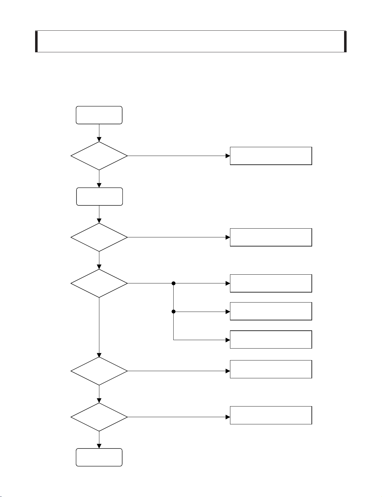
ELECTRICAL TROUBLESHOOTING GUIDE
INSERT
POWER CORD.
TURN ON
THE RED LED?
IS POWER ON?
CHECK POWER PLUG
AND POWER SUPPLY CIRCUIT.
DOES INITIAL
READ WORK?
DOES IT PLAY?
YES
NO
YES
YES
OK
NO
YES
NO
NO
CHECK POWER SUPPLY CIRCUIT.
CHECK LASER CIRCUIT.
CHECK TRACKING SERVO CIRCUIT.
TURN POWER ON.
CHECK FOCUS CIRCUIT.
CHECK DISC.
DOES IT OUTPUT
AUDIO?
YES
NO
CHECK AUDIO CIRCUIT.
1. Power check flow
SECTION 2. AUDIO PART
— 2-2 —
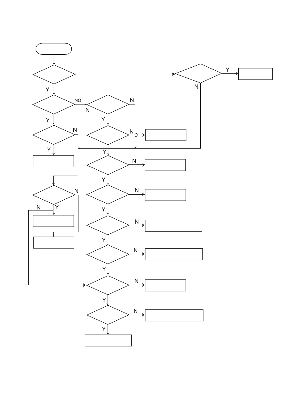
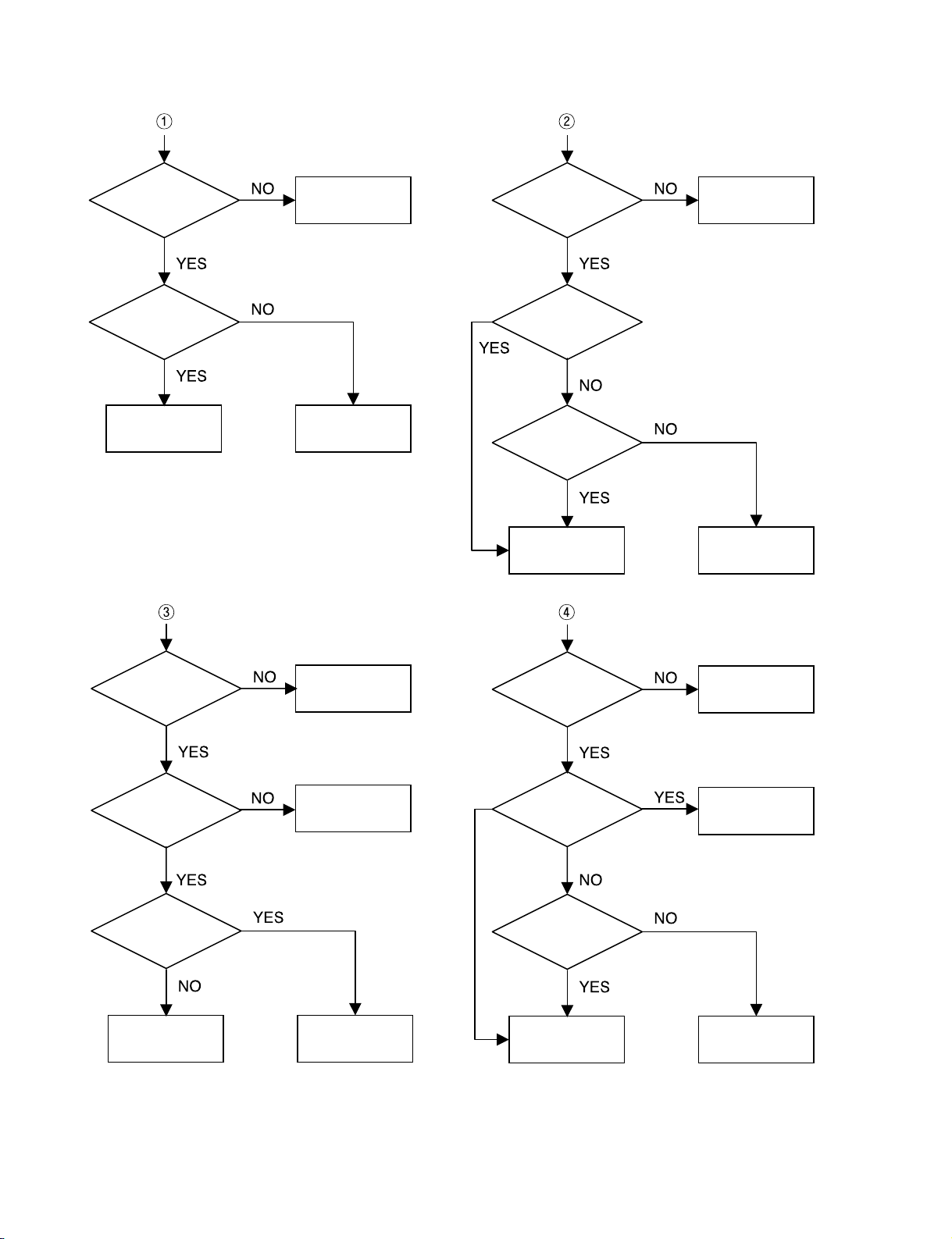
2.AUDIO µ.COM CIRCUIT
POWER ON
Does it appear
DVD Error at
FLD?
Does AV 1/2, TV, AUDIO,
OPTICAL IN, COAXIAL IN, FM87.5
appear at FLD?
Check
Connector(PN902)if
is normally.
Check power part
of Main B/D.
Check oscillator
of x101.
Check if IC101
PIN1 is High.
Check if IC101
PIN11 is High.
Check if IC101 PIN
17, 46, 72, 90 is high
(5V).
Check if IC101
PIN26 is High.
Replace IC101.
Does CD/DVD
appear at FLD?
Reconnet it.
Refer to SMPS
OK.
Refer to oscillator
Circuit.
Check DVD Reset Waveform.
Check IC101 Reset Wavefrom.
Check 5V line.
Check Power dection Circuit.
Does LOADING
appear at FLD?
Does no Disc or
Time appear at FLD?
Check if DVD an Audio
Micom Interface is OK.
Check power.
Check DVD Module.
Check SMPS.
— 2-3 —
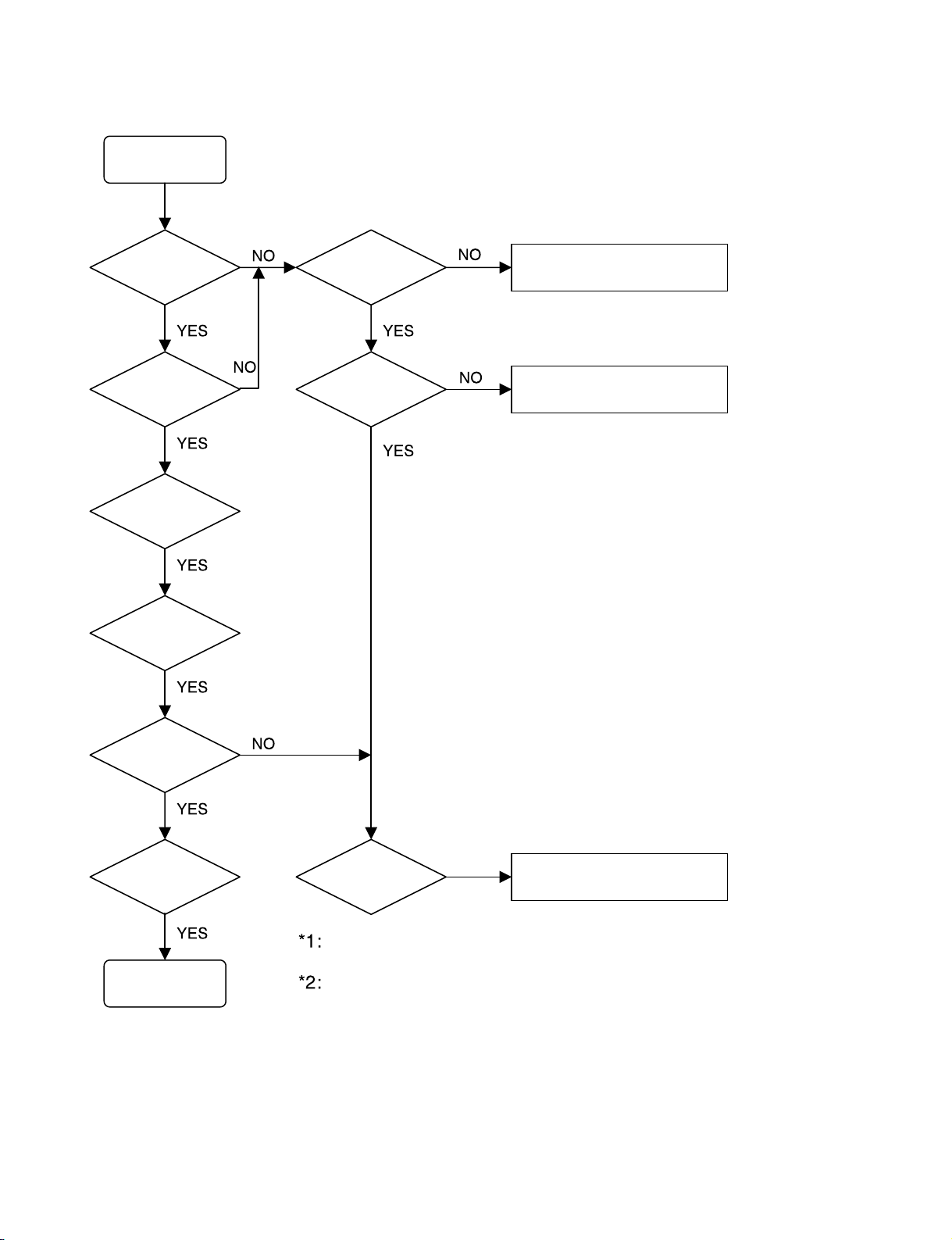
3.FRONT CIRCUIT (1/2)
POWER ON
TURN ON
THE GREEN LED?
IS DIGITRON
ON NORMALLY?
Check If
All Buttens
Are OK.
Check If
The volume is
OK.
Check If
The headphone
is OK.
Check If
The Remocon
is OK.
FRONT B/D OK.
When it is needed to reconnect FFC cable into PN103/PN104,
short ZD 902 + and screw(chassis GND) near to ZD902.
PN104 pins
PIN2 : -27.5V
PIN3 : -23.0V
PIN4 : 5.0V
PIN11 : -34.0V
Check IF
THE PN103/PN104
IS OK?
Check IF the
FRONT POWER
IS OK(*2)
RECONNECT.
(REFER TO NOTICE *1)
REFER TO SMPS PART.
Check IF
The VFD001 PINS
ARE OK.
CHECK PATTERN
AND RESOLDERING.
— 2-4 —
4.FRONT CIRCUIT (2/2)
Check if
The Power part of the
Front is OK.
Check if
The Power part of the
Front is OK.
Check if
R036~R040
OK.
Check if
PN104 pin13, 15
waveform OK.
Check if
R032, R033
OK.
REFER TO
MICOM CIRCUIT.
REPLACE
R036~R040.
REFER TO
POWER(SMPS).
REFER TO
POWER(SMPS).
REFER TO
MICOM CIRCUIT.
REPLACE
R032, R033.
Check if
the power part of the
Front is OK.
Check if
The PN104 pin17
is Low.
REFER TO
POWER (SMPS).
REFER TO
POWER (SMPS).
REFER TO
POWER (SMPS).
REFER TO
POWER (SMPS).
Check if
Headphone jack
in JK001 is OK.
REFER TO
MICOM CIRCUIT.
CHECK MAN B/D.
Check if
the power part of the
Front is OK.
Check if
the RMC001 volume
is OK(5V).
Check if
the Remocon
Waveform of the
PN104 pin7.
Replace RMC001.
Check RMC
Circuit.
2-7 2-8
❏ SCHEMATIC DIAGRAMS
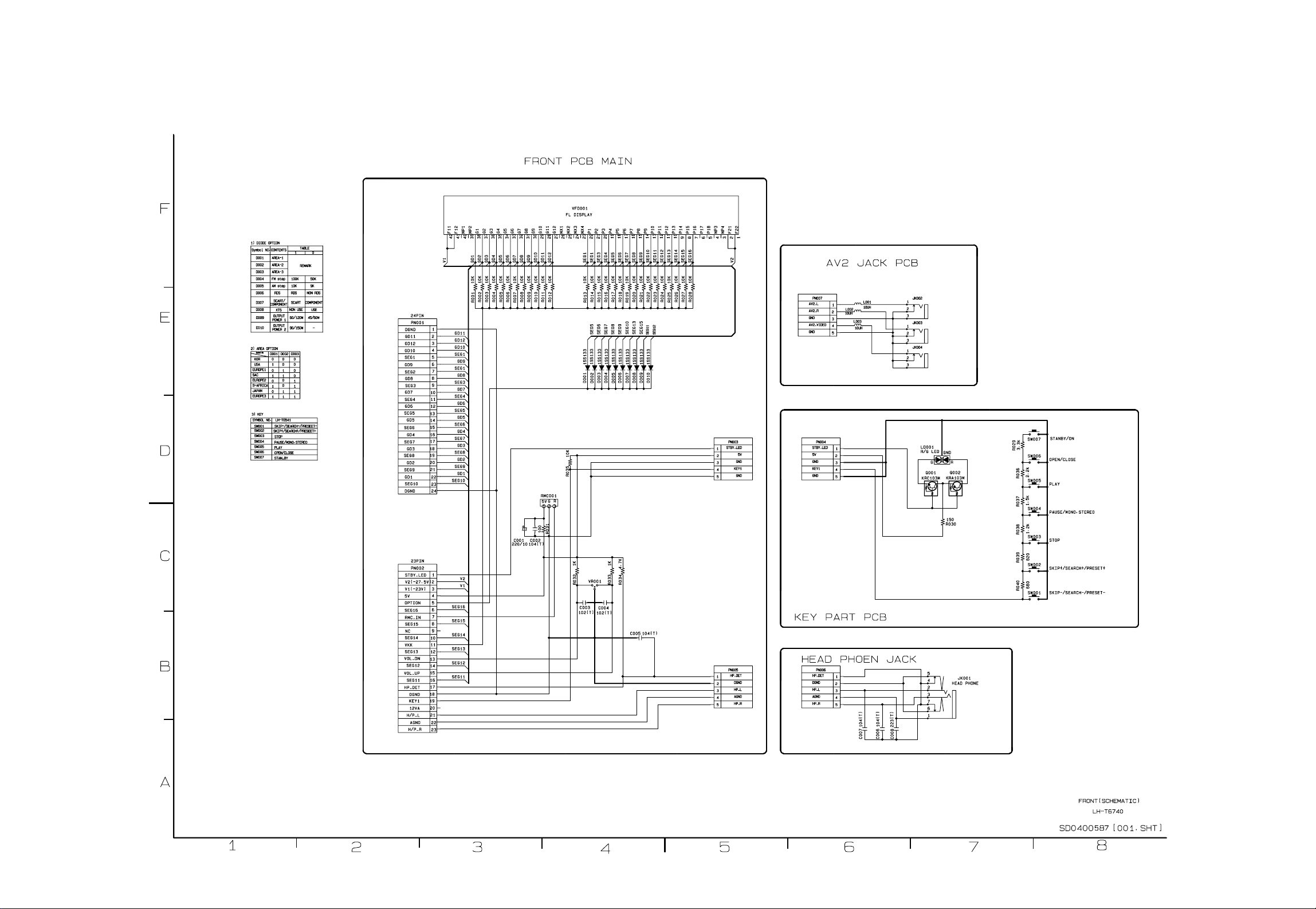
• FRONT SCHEMATIC DIAGRAM
2-9 2-10
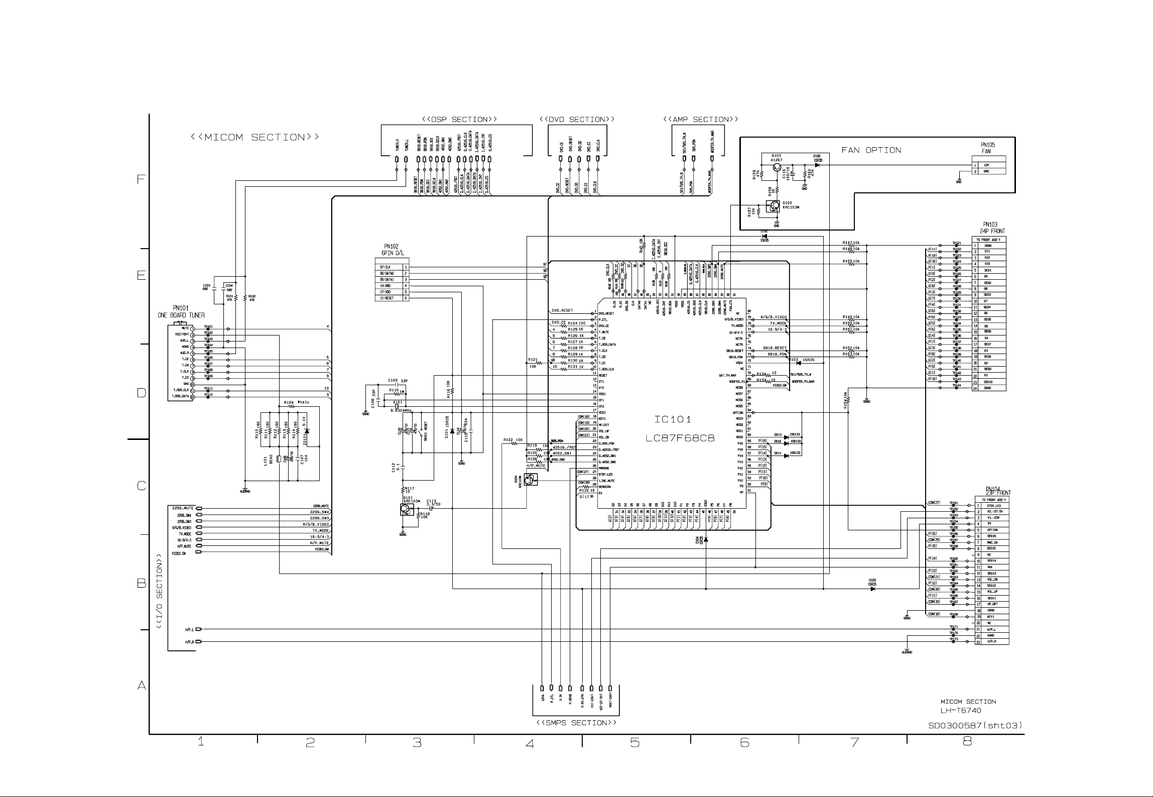
• MICOM SCHEMATIC DIAGRAM
2-11 2-12
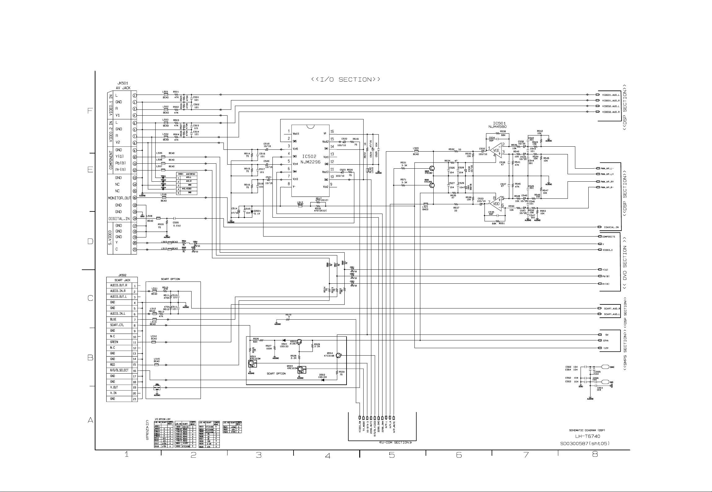
• I//O SCHEMATIC DIAGRAM
2-13 2-14
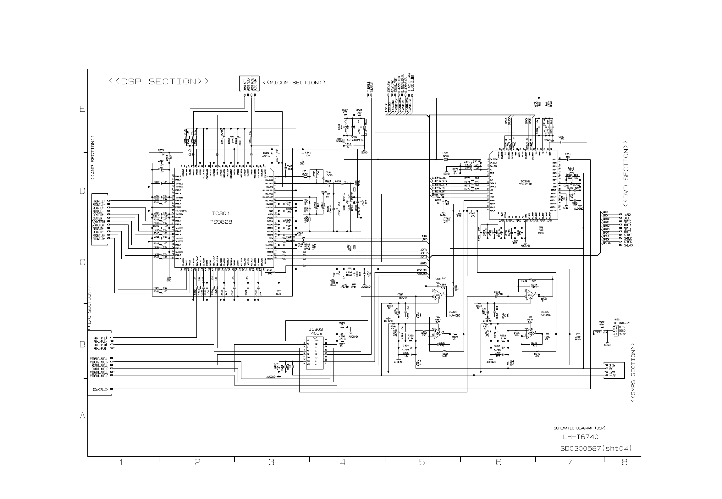
• DSP SCHEMATIC DIAGRAM
2-15 2-16
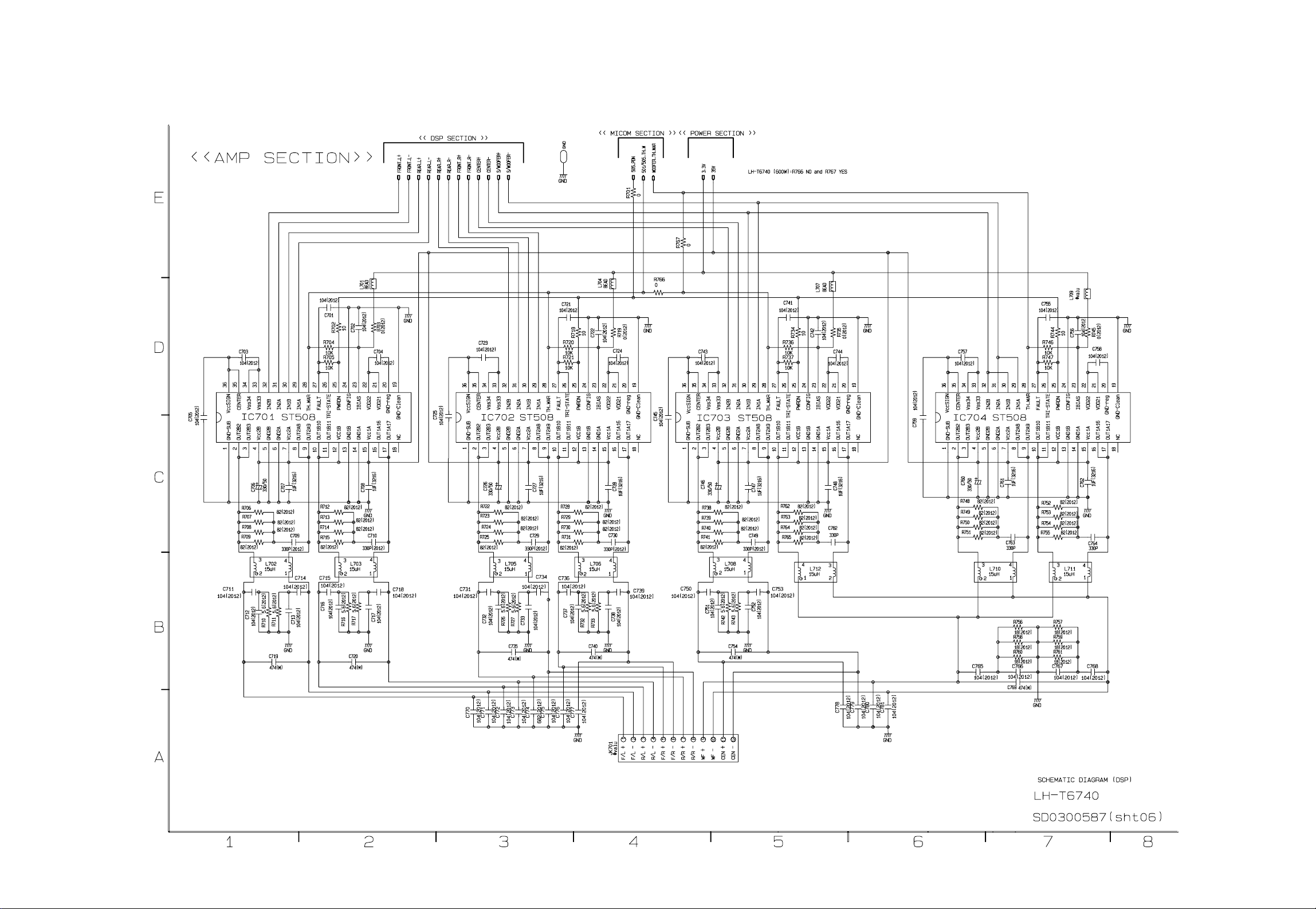
• AMP SCHEMATIC DIAGRAM
2-17 2-18
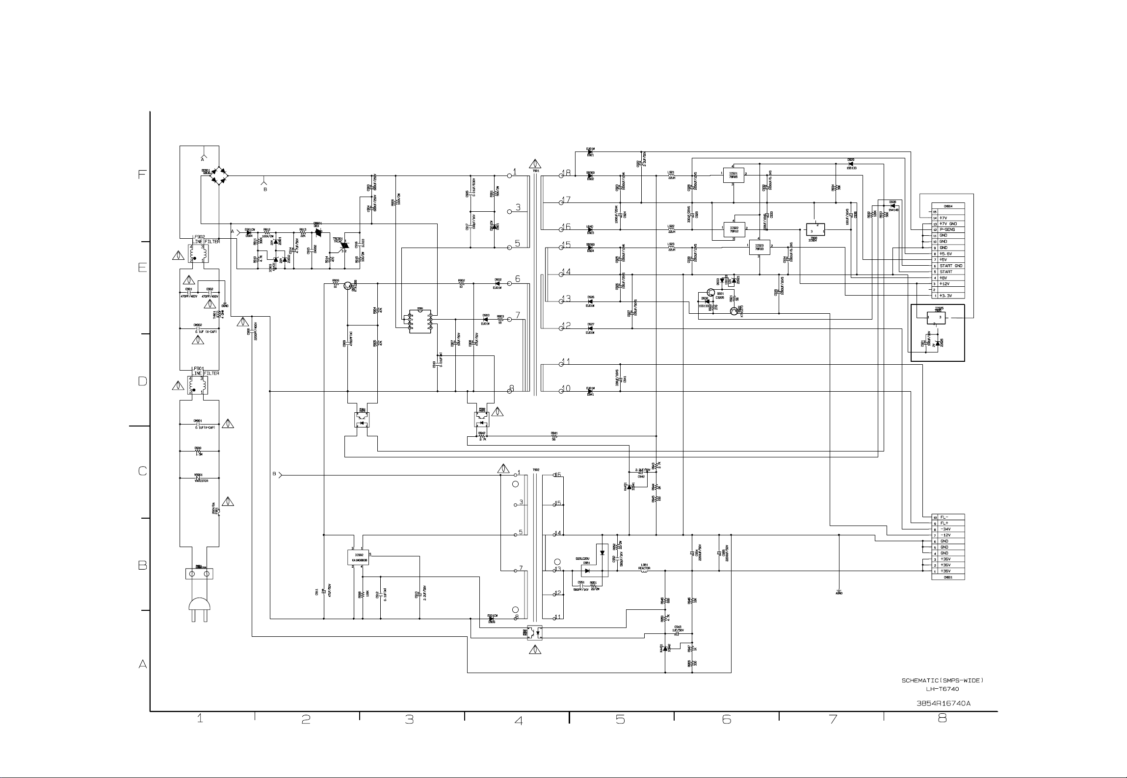
• SMPS-WIDE SCHEMATIC DIAGRAM
Loading…
View the manual for the LG LH-T6745X here, for free. This user manual comes under the category home cinema sets and has been rated by 1 people with an average of a 7.5. This manual is available in the following languages: English. Do you have a question about the LG LH-T6745X?
Ask your question here
Frequently asked questions
Can’t find the answer to your question in the manual? You may find the answer to your question in the FAQs about the LG LH-T6745X below.
What is HDMI?
HDMI stands for High-Definition Multimedia Interface. An HDMI cable is used to transport audio and video signals between devices.
How can I best clean my home cinema set?
A slightly damp cleaning cloth or soft, dust-free cloth works best to remove fingerprints. Dust in hard-to-reach places is best removed with compressed air.
Wat is Dolby Atmos?
Dolby Atmos is a technology that ensures that the sound is reflected from the ceiling to where you are listening. This makes it possible to create a 5.1 effect with only 1 speaker.
Is the manual of the LG LH-T6745X available in English?
Yes, the manual of the LG LH-T6745X is available in English .
Is your question not listed? Ask your question here
- Потребитель
- Бизнес
Menu
- Потребительские товары
- Поддержка
- Поддержка товара
ГАРАНТИЯ
Краткое описание гарантии производителя
Срок покрытия
- Работа : 12 месяцев since 01/10/2007
- Запчасти : 12 месяцев since 01/10/2007
Точные условия гарантии доступны в гарантийном талоне, входящем в обязательный пакет документов, прилагаемых при покупке техники.
Если вам необходим ремонт, воспользуйтесь онлайн свяжитесь с нами.Пожалуйста, заранее подготовьте серийный номер вашего изделия и документы, подтверждающие покупку (чек). В негарантийных случаях может взиматься плата за диагностику, ремонтные работы и запчасти.
-
-
Исправление проблем
Я хочу включить автоматическое включение саундбара
- Функция автоматического включения используется для того, чтобы саундбаравтоматически включался при включении телевизора, когда телевизор и саундбаризначально выключены, когда подключен оптический кабель или Bluetooth (BT).Вы можете использо…
-
-
-
Исправление проблем
Нет звука при подключении ТВ к саундбару с помощью Оптического кабеля
- Нет звука при подключении ТВ к саундбару по оптическому кабелю Подключение саундбаров LG к телевизору с помощью оптического кабеля 1. Саундбары с функцией LG Sound Sync (аппаратной функциисинхронизации воспроизведения видео и аудио)1) по оп…
-
-
-
Исправление проблем
[Саундбар] — Совместимость устройств Dolby Atmos®
- [Саундбар] — Совместимость устройств Dolby Atmos®Dolby Atmos — новейший аудиоформат, расширяющие существующие ранее технологииобъемного звучания Dolby, добавляя вертикальные каналы аудиосцен иобеспечивающий глубокие ощущения погружения в пр…
-
-
-
Ремонт
[Саундбар LG] Саундбар не включается
- Попробуйте выполнить следующие действия, если звуковая панель не включается. * Убедитесь, что розетка питания, к которой подключена звуковая панель, исправна. Убедитесь в этом, подключив к розетке другое электрическое устройство, например з…
-
-
-
Исправление проблем
[Саундбар LG] Как включить функцию «Автопитание»
- Способ включения/выключения функции автоматического питания саундбара можетразличаться в зависимости от модели.Пульты дистанционного управления и кнопки, показанные в этом руководстве, могутотличаться от ваших.Пожалуйста, обратитесь к руков…
-
-
-
Исправление проблем
[Саундбар LG] Подключение беспроводного сабвуфера и тыловых динамиков к саундбару
- Автоматическое подключение беспроводного сабвуфера и беспроводных тыловыхдинамиковПосле завершения установки беспроводной сабвуфер и беспроводные тыловые динамикибудут автоматически подключены к звуковой панели.Подключите саундбар к сабвуфе…
-
Узнай больше
-
Новых
продуктов нет.
Перейти к контенту
Домашние кинотеатры LG
- Размер инструкции: 1.08 Мб
- Формат файла: pdf
Если вы потеряли инструкцию от домашнего кинотеатра LG LH-T6745, можете скачать файл для просмотра на компьютере или печати.
Инструкция для домашнего кинотеатра LG LH-T6745 на русском языке. В руководстве описаны возможности и полезные функции, а также правила эксплуатации. Перед использованием внимательно ознакомьтесь с инструкцией.
Чтобы не читать всю инструкцию вы можете выполнить поиск по содержимому внутри инструкции и быстро найти необходимую информацию. Рекомендации по использованию помогут увеличить срок службы домашнего кинотеатра LG LH-T6745. Если у вас появилась проблема, то найдите раздел с описанием неисправностей и способами их решения. В нем указаны типичные поломки и способы их решения.