
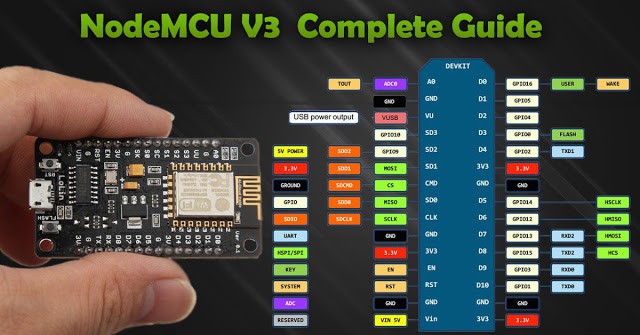
Introduction: Getting Started With ESP8266(LiLon NodeMCU V3) Complete Guide for IoT Startup With Example(as Server)
Things You Need:
- NodeMCU Flasher Master (Flasher)
- NodeMCU Firmware (Firmware)
- Latest Arduino IDE (Arduino)
- NodeMCU V3
- Micro USB Cable
- LED
Features
- Open-source, Interactive, Programmable, Low cost, Simple, Smart, WI-FI enabled
- Arduino-like hardware IO
- Lowest cost WI-FI
Step 1: Installing the Firmware
In NodeMCU Boards the first thing you need is to install the Firmware to the board
the following method works for all NodeMCU Boards
- Open the NodeMCU flasher master folder than open the win32/win64 folder as your computer. now open the folder Release than double click ESP8266Flasher.
- Select the COM Port.
- Goto config tab
- click on the small gear and open up the firmware which you have downloaded
- go to the advenced tab and select the desired Baudrate
- Goto the Operation tab and click on Flash Button.
Step 2: Preparing the Arduino IDE
After Installing the firmware you are ready to do the programming with the ESP8266
- Install the Arduino IDE
- open the Arduino IDE from the desktop icon
- Click on File tab and than open preferences
- In the additional Boards Manager URLs add the following link (http://arduino.esp8266.com/stable/package_esp8266com_index.json) and click OK
- Goto Tools>Borads>Boards Manager
- In the search field type esp8266 click the esp8266 by ESP8266 Community option and click Install
Step 3: Code…
Now you can do whatever you want with your NodeMCU board
Following is an example for led blinking with NodeMCU board via webserver
- In arduino IDE goto tools>Boards>select NODEMCU 1.0 (ESP — 12E Module)
- again goto tools and select port.
- Change the Wifi name and password from the following code.
- Now click on Upload button to upload the following code.
- Connect the led’s positive leg on D9 pin of board and negative to the ground of the code.
- Power up the board and open the serial monitor from arduino IDE
- after connecting to the wifi it will show you the IP address.
- type that IP address on the web browser(Edge, Chrome, Firefox etc..)
- A webpage will open you can change the status of LED by turning it ON or OFF.
#include<ESP8266WiFi>

const char* ssid = "Tenda"; //your WiFi Name
const char* password = "12345678";  //Your Wifi Password
int ledPin = 03;
WiFiServer server(80);
void setup() {
  Serial.begin(115200);
  delay(10);
  pinMode(ledPin, OUTPUT);
  digitalWrite(ledPin, LOW);
  Serial.println();
  Serial.println();
  Serial.print("Connecting to ");
  Serial.println(ssid);
  WiFi.begin(ssid, password);
  while (WiFi.status() != WL_CONNECTED) {
    delay(500);
    Serial.print(".");
  }
  Serial.println("");
  Serial.println("WiFi connected");
  server.begin();
  Serial.println("Server started");
  Serial.print("Use this URL to connect: ");
  Serial.print("http://");
  Serial.print(WiFi.localIP());
  Serial.println("/");
}

void loop() {
  WiFiClient client = server.available();
  if (!client) {
    return;
  }
  Serial.println("new client");
  while(!client.available()){
    delay(1);
  }
  String request = client.readStringUntil('\r');
  Serial.println(request);
  client.flush();
  int value = LOW;
  if (request.indexOf("/LED=ON") != -1)  {
    digitalWrite(ledPin, HIGH);
    value = HIGH;
  }
  if (request.indexOf("/LED=OFF") != -1)  {
    digitalWrite(ledPin, LOW);
    value = LOW;
  }
  client.println("HTTP/1.1 200 OK");
  client.println("Content-Type: text/html");
  client.println("");
  client.println("");
  client.println("");
  client.print("Led is : ");
  if(value == HIGH) {
    client.print("On");
  } else {
    client.print("Off");
  }  client.println("");
client.println(" On ");
   client.println(" Off ");
  client.println(" ");
     delay(1);
   Serial.println("Client disonnected");
  Serial.println("");   }
//code copied from link
If you encounter any problem comment it down
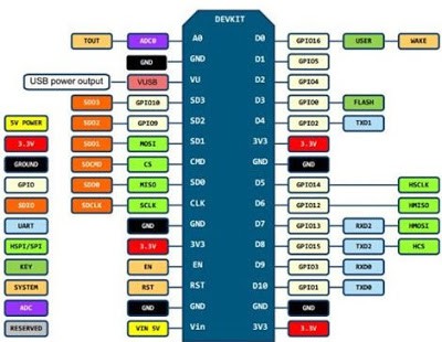
ESP8266 NodeMCU V3 (LoLin)
Распиновка (pinout) ESP8266 NodeMCU V3 «LoLin» совпадает с распиновкой ESP8266 NodeMCU V2 «Amica», за исключением двух зарезервированных у NodeMCU V2 выводов RSV (reserved). У NodeMCU V3 к ним подключена «земля» и напряжение 5V с USB-разъема.
Кроме использования двух зарезервированных выводов, плата NodeMCU V3 практически не отличается от V2. В обеих платах используются одинаковые микроконтроллеры ESP8266, они имеют одинаковое количество памяти. А к немногим отличиям можно отнести увеличенные габариты у V3, что неудобно при работе с макетными платами, и использование микросхемы CH340G в качестве моста USB – UART, вместо CP2102, что никак не сказывается на работе с платой, кроме необходимости выбора соответствующего драйвера.
")
Описание и назначение выводов NodeMCU V3 ESP8266
GND — общий провод, «земля»
Выводы питания
Vin — вывод для подключения внешнего источника питания 5V. Стабилизатор AMS1117-3.3 позволяет подавать питание на Vin в широком диапазоне от 5 до 10 V. Хотя стабилизатор допускает подачу более высокого напряжения (до 15 V), но без дополнительного охлаждения может возникать перегрев чипа.
3.3V — контакт, на который подается выходное напряжение внутрисхемного стабилизатора. Может быть использован для питания подключаемых к плате датчиков. Суммарная максимальная нагрузка всех выводов 3.3V не должна превышать 300мА.
V USB — вывод, на который заведено напряжение 5V с USB-разъема.
Выводы GPIO
GPIO (General Purpose Interput Output) — контакты ввода/вывода общего назначения. Могут быть сконфигурированы как входы или выходы и программно назначены на различные функции.
Выводы управления
RST (Reset) — вывод используется для сброса микроконтроллера ESP8266.
EN (Chip Enable) — при подаче на контакт сигнала высокого уровня, микроконтроллер ESP8266 переходит в рабочий режим, при сигнале низкого уровня — в режим энергосбережения.
WAKE — контакт используется для пробуждения чипа ESP8266 из режима глубокого сна (deep-sleep mode).
АЦП (ADC)
ADC0 / TOUT — вывод встроенного 10-разрядного аналого-цифрового преобразователя (АЦП). Преобразованные значения лежат в интервале 0-1023. Платы разработки NodeMCU V2 и V3 поставляются с внутренним делителем напряжения, поэтому входной диапазон составляет от 0 до 3,3 В. Диапазон входного напряжения для АЦП в кристалле ESP8266: 0 — 1 В.
UART
UART (Universal Asynchronous Receiver-Transmitter) — асинхронный последовательный интерфейс устанавливает связь с другими устройствами по шине UART. У контроллера ESP8266 два модуля UART. Максимальная скорость передачи данных, заявленная производителем, 4,5 Mbps.
SPI
SPI (Serial Peripheral Interface) — последовательный периферийный интерфейс. NodeMCU имеет два SPI (SPI и HSPI) в ведущем и подчиненном режимах.
SDIO
SDIO — интерфейс безопасных цифровых входов/выходов, предназначен для коммутации с внешней флэш-памятью стандарта SD по последовательной шине.
Reserved
Зарезервированные выводы.
FLASH
Кнопка Flash на NodeMCU подключает к земле GPIO0. Ее можно использовать как обычную кнопку. Если программно подтянуть вывод GPIO0 с помощью внутреннего подтягивающего резистора к высокому уровню, то появление низкого уровня на этом выводе будет означать, что кнопка нажата.
Интерфейс I2C — последовательная асимметричная шина. I2C используется для подключения датчиков и периферийных устройств. NodeMCU ESP8266 не имеет аппаратных выводов I2C, но интерфейс можно реализовать программно. Поддерживаются как I2C Master, так и I2C Slave. Обычно в качестве контактов I2C используются следующие выводы.
- GPIO5: SCL
- GPIO4: SDA
PWM (pulse-width modulation) — широтно-импульсная модуляция (ШИМ) управляет мощностью методом пульсирующего включения и выключения вывода. NodeMCU поддерживает программный ШИМ на выводах, обозначенных на рисунке изгибающейся линией.
Onboard LED
Плата имеет только один встроенный светодиод. Он подключен к GPIO2.
Материалы по теме:
- NodeMCU схема (ESP8266, ESP32)
- Скачать драйвер CH340 для NodeMCU
- Скачать MicroPython ESP8266
|
Размещение этой статьи на других сайтах как полностью, так и частично разрешено только после согласования с администрацией myROBOT.RU |
Описание:
Плата NodeMcu v3 Lolin построена на микроконтроллере ESP8266 с интерфейсом Wi-Fi и конвертере USB-UART на базе микросхемы CH340G. Плата содержит всё необходимое для поддержки установленного микроконтроллера: 11 портов ввода-вывода общего назначения, которые дополнительно могут использоваться в качестве ШИМ, АЦП, UART, SPI, I²C/TWI, SDIO и разъем micro-USB, кнопка сброса и кнопка отладки. Устройство может получать питание непосредственно от USB, либо от вывода Vin, контроллер автоматически определяет и выбирает наиболее подходящий источник тока. Чтобы начать, просто соедините его с компьютером посредством кабеля USB A -> Micro-B (продается отдельно) и установите драйвера и среду разработки на компьютер.
Для данной платформы можно использовать среду разработки ESPlorer IDE с языками программирования LUA, Python и AT команды, или среду разработки Arduino IDE с языком программирования C/C++
Этот модуль совместим с макетными и монтажными платами с шагом 2,54 мм. Для удобства подключения питания и периферии к данному контроллеру можете использовать плату расширения ввода/вывода.
Спецификация:
Распиновка:
Выводы питания
Выводы управления
Выводы GPIO
ADC
UART
SPI
I²C
SDIO
Документация и другая информация:
Спецификация ESP8266EX (872k pdf)
Техническое описание микросхемы Espressif Systems ESP8266EX — высокоинтегрированная система на кристалле со встроенной поддержкой WiFi.
Спецификация CH340 (572k pdf)
Техническое описание микросхемы WCH CH340 — преобразователь USB-UART.
Спецификация AMS1117 (188k pdf)
Техническое описание микросхемы Advanced Monolithic Systems AMS1117 — линейный стабилизатор напряжения.
Драйвер CH340G для windows
Среда разработки ESPlorer IDE
Среда разработки Arduino IDE
NodeMcu is an ESP8266 based platform for creating various Internet of Things (IoT) devices. The module can send and receive information to a local network or to the Internet using WiFi. An inexpensive module is often used to create distance-controlled smart home systems or Arduino robots. In this article, we will look at the board description, version differences, and NodeMcu v3 pinout the latest version of the NodeMcu Esp8266 module . We will also briefly review the Lua language in which you need to write programs for NodeMcu.
Description of ESP8266 NodeMcu v3
Technical characteristics of the module:
- Supports Wi-Fi protocol 802.11 b / g / n;
- Supported Wi-Fi modes – access point, client;
- Input voltage 3.7V – 20 V;
- Operating voltage 3V-3.6V;
- Maximum current 220mA;
- Built-in TCP / IP stack;
- Operating temperature range from -40С to 125С;
- 80 MHz, 32-bit processor;
- Wake up time and send packets 22ms;
- Built-in TR switch and PLL;
- The presence of power amplifiers, regulators, power management systems.
There are several generations of NodeMcu boards – V1 (version 0.9), V2 (version 1.0) and V3 (version 1.0). Designations V1, V2, V3 are used when selling in online stores. Boards often get confused – for example, V3 is outwardly identical to V2. Also, all boards work on the principle of open-source, so they can produce any company. But Amica, DOIT and LoLin/Wemos are currently producing NodeMcu boards.
Differences from other modifications
Boards of generation V1 and V2 are easy to distinguish – they have different sizes. Also, the second generation is equipped with an improved modification of the ESP-12 chip and 4 MB of flash memory. The first version, outdated, is made in the form of a bright yellow platform. It is inconvenient to use it, since it covers 10 outputs of the breadboard. The second generation board was made to correct this drawback – it has become narrower, the outputs are well suited to the board contacts. V3 boards look no different from V2; they have a more reliable USB output. The LoLin company releases the V3 board, one of the differences from the previous board is that one of the two reserved outputs is used for additional ground, and the second for USB power supply. The board also has a larger size than previous types.
Where to buy NodeMCU and ESP8266 modules
Today, there are many fairly inexpensive modifications of the ESP8266-based boards available on the market. We made a small selection of the most interesting options:
Power NodeMcu Module
There are several ways to supply power to the module:
- Supply 5-18 V through Vin;
- 5V via USB or VUSB pin;
- 3.3V via 3V pin.
Benefits of NodeMcu v3
- The presence of a UART-USB interface with a micro USB connector makes it easy to connect the board to a computer.
- The presence of flash memory at 4 MB.
- Ability to update firmware via USB.
- Ability to create scripts on LUA and save them in the file system.
Disadvantages of the NodeMcu module
The main disadvantage is the ability to execute only LUA scripts located in RAM. This type of memory is small, the volume is only 20 KB, so writing large scripts causes a number of difficulties. First of all, the whole algorithm will have to be divided into linear blocks. These blocks must be written to separate system files. All of these modules are executed using the dofile operator.
When writing, you must follow the rule – when exchanging data between modules, you need to use global variables, and when calculating inside modules, you need to use local variables. It is also important to call the collectgarbage function (garbage collector) at the end of each script you write.
Nodemcu v3 datasheet
nodemcu V3 module has 11 general-purpose I/O pinout. In addition, some of the conclusions have additional functions:
- D1-D10 – outputs with pulse-width modulation;
- D1, D2– pins for the I²C / TWI interface;
- D5 – D8 – pins for the SPI interface;
- D9, D10 – UART;
- A0 – input from the ADC.
How do I connect to NodeMCU?
To get started with NodeMcu, you need to connect the board to the computer. The first step is to install the CP2102 driver and open the Arduino IDE. Then you need to find in the “File” – “Settings” and in the “additional links for the board manager” window insert the link http://arduino.esp8266.com/versions/2.3.0/package_esp8266com_index.json
After that, in the menu “documents” – “board” “board manager” select “esp8266” and install the latest version. After the done actions in the menu “tools” – “board” you need to find NodeMCU.
After all the necessary data is installed and copied, you can start working.
Nodemcu esp8266 examples
An example of connecting an LED to NodeMCU schematic
The schematic diagram of the connection is shown in the figure.
The final layout of the layout is as follows:
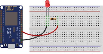
The board itself runs on 3.3 V, so you need to use a resistor to connect the LED. In this example, a 65-ohm resistor is taken for the red LED.
In a similar way, a photodiode is also connected to the board:
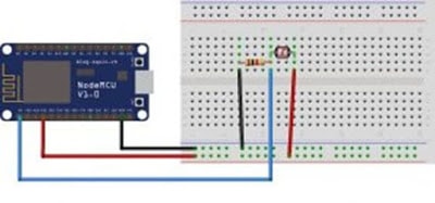
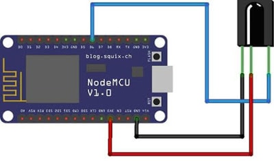
The NodeMCU V3 board can also be used for IR control. To control you need a remote control with an IR receiver and the platform itself. The infrared receiver is connected as shown below:
Firmware for esp8266 NodeMcu
The platform is loaded with the standard Node MCU firmware, in which the Lua language interpreter is integrated. Using Lua commands, you can do the following:
- Connect to a Wi-Fi access point;
- Work as a Wi-Fi access point;
- Switch to deep sleep mode to reduce energy consumption;
- Turn on or off the LED on the GPIO16 output;
- Perform various operations with files in flash memory;
- Search for an open Wi-Fi network, connect to it;
- MAC address output;
- Manage user timers.
For programming NodeMCU, you can use the Arduino IDE or the SDK development kit – ESPlorer. This complex has several differences:
- It can work on many different platforms;
- It has support for multiple open files;
- Allows highlighting the Lua language code;
- The ability to smartly send files;
- The ability to support several types of firmware at the same time.
To ensure correct and stable operation, you need to update the firmware to the latest version. There are several upgrade methods – cloud service, Docker Image, and compilation on Linux. Each of these methods has its pros and cons. The simplest and most understandable is the first method.
Collecting firmware in the cloud service
Cloud service has a simple and convenient interface. Work begins with an email. Next, you will be prompted to select the type of firmware – stable firmware or tested. The first is used for training and creating a large number of objects, so it is recommended to choose it. The next step is to connect the necessary modules. By default, several key points have already been recorded, the rest should be included only if necessary. Then additional options are selected. Among them there is FatFS support for reading an SD card or turning on debugging mode.
After the start of the assembly, a letter will arrive in the mail signaling the start of the process. After a while, the second letter will come – it will be offered to choose the version of float (fractional numbers) or integer (integers).
After clicking on the received link, you will need to download the bin file and place it in Resources – Binaries. The nodemcu_integer_0.9.5_20150318.bin file will be located there, which must be deleted. As a result, the contents of the folder will look as follows.
NodeMcu Firmware Update
For the correct and stable operation of the board, you need to overwrite esp_init_data_default.bin. You can download it on the official website. The necessary file must be put back into the NodeMCU Flasher firmware system along the Resources – Binaries path, having previously deleted the old file from it.
Then you can connect NodeMCU and proceed with the upgrade. First you need to change the settings – in NodeMCU Flasher, in the Config tab, you need to select the assembled firmware file instead of INTERNAL://NODEMCU.
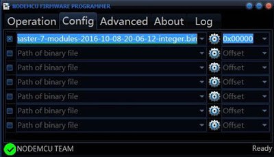
Leave the rest unchanged, go to Operations and click Flash. As soon as the firmware finishes, you need to switch to Config again and specify the path esp_init_data_default.bin in the first line. The address where you want to move this file is also indicated. For NodeMCU, select address 0x3FC000. After that, you need to return to Operations again and click Flash.
After that, you need to reformat the entire file system. To do this, run ESPlorer, be sure to set the exchange speed to 115200 and restart NodeMCU. After all the above steps there will be a new firmware version. The debug board is completely reflashed and ready to work.
Short description of the Lua language
Lua has a simple syntax and powerful data description constructs based on arrays and extensible semantics. This powerful programming language is used to create software, expand various games. Unlike other languages, Lua has more flexible and more powerful designs.
Flashing LED on Lua
You can consider the simplest scheme – blinking LED. This example will help you learn how to work with GPIO pins. The LED must be connected as shown in the diagram.
Then you need to write the following sketch to the left window of ESPlorer:
pin_number = 1
gpio.mode (pin_number, gpio.OUTPUT) //setting the operating mode to the output
gpio.write (pin_number, gpio.HIGH) //high level setting
gpio.write (pin_number, gpio.LOW) //low level setting
gpio.serout (1, gpio.HIGH, {+990000,990000}, 10, 1) //set the LED to blink 10 times
After that you need to save the script called init.lua. Immediately after this, the written code will be automatically loaded into the debug board and executed. If the operation is successful, the debug board will blink with an LED.
It is important to note that the board runs the script on its own, the connection to the computer is necessary only for power supply.
Если вы делаете устройство, которое должно входить в интернет без проводов, NodeMCU станет для него отличной основой. NodeMCU — это полноценная платформа на основе модуля ESP8266, который умеет принимать и посылать данные в локальную сеть или интернет через Wi-Fi.
Используйте NodeMCU вместо или вместе с Arduino, чтобы сделать умный дом, проекты интернета вещей или удалённый мониторинг сенсоров.
Родное напряжение модуля — 3,3 В.
Существуют разные версии ESP8266, но почти для всех используется один и тот же способ настройки среды разработки Arduino IDE.
Настройка ESP8266 в Arduino IDE
Для этой процедуры необходим доступ в интернет, так как Arduino IDE требуется скачать дополнительные пакеты.
Заходим в настройки Arduino IDE:

В поле Дополнительные ссылки для Менеджера плат пишем такую ссылку:
http://arduino.esp8266.com/stable/package_esp8266com_index.json

Жмем ОК и переходим в окно менеджера плат:

В строке поиска менеджера плат пишем «esp».

В самом низу будет нужный нам пакет «esp8266 by ESP8266 Community». Выбираем его и жмем кнопку «Установка».

Спустя некоторое время пакет скопирует необходимые файлы и в Arduino IDE можно будет выбрать нужную нам плату.
Если возникает «Ошибка при загрузке http://downloads.arduino.cc/packages/package_index.json», зайдите в папку
C:\Users\%UserName%\AppData\Local\Arduino15
удалите все файлы, кроме preferences.txt. Перезапустите среду разработки Arduino и снова установите в Менеджере плат пакет «esp8266 by ESP8266 Community».
Распиновка
")
Скачать драйвера CH340 для всех операционных систем
Скачать драйвер FTDI FT232R для Windows