
Частотные преобразователи LS ELECTRIC М100
Оптимальная компактная
серия преобразователей частоты
- →
- →
-
Частотные преобразователи LSIS серии М100
Оптимальная компактная серия преобразователей частоты M100 подходит для небольших насосов, вентиляторов, конвейерных установок.
Серия M100 имеет встроенный фильтр ЭМС (C2 Класса), встроенный тормозной прерыватель, возможность установки на DIN-рейку и потенциометр.


Преобразователь имеет быстрый доступ к большинству программ через внешнюю панель управления, функцию быстрого подключения к удаленным устройствам, возможность копирования параметров на соседние устройства и внешний пульт управления.

Благодаря возможности контактной установки (2 мм между преобразователями), подходит для решения задач в ограниченном пространстве.

Преобразователи M100 серии имеют международный стандарт использования.

|
LSLV M100-EOFN |
0001 |
0002 |
0004 |
0008 |
0015 |
0022 |
|
|
Мощность двигателя, л.с. |
0.125 |
0.25 |
0.5 |
1.0 |
2.0 |
3.0 |
|
|
Мощность двигателя, кВт: |
0.1 |
0.2 |
0.4 |
0.75 |
1.5 |
2.2 |
|
|
Номинальная мощность на выходе: |
Номинальный мощность, кВА: |
0.3 |
0.6 |
0.95 |
1.9 |
3.0 |
4.5 |
|
Номинальный ток, А: |
0.8 |
1.4 |
2.4 |
4.2 |
7.5 |
10.0 |
|
|
Частота, Гц |
0~400 |
||||||
|
Напряжение, В: |
3 фазы 200-240 В |
||||||
|
Номинальная мощность на входе: |
Напряжение, В: |
1 фаза 200-240 В переменного тока (от -15% до +10%) |
|||||
|
Частота, Гц |
50~60 Гц (± 5%) |
||||||
|
Номинальный ток, А: |
1.0 |
1.8 |
3.7 |
7.1 |
13.6 |
18.7 |
|
|
Тип охлаждения: |
Естественное |
Принудительное |
|||||
|
Вес, кг: |
0.66 |
1 |
1.45 |
JS-Technik GmbH — Lether Gerwerbestrasse 10 — 26197 Großenkneten www.js-technik.de
Safety Information
Indicates an imminently hazardous situation which, if not avoided, will result in severe injury or
death.
Indicates a potentially hazardous situation which, if not avoided, could result in injury or
death.
Indicates a potentially hazardous situation that, if not avoided, could result in minor injury or
property damage.
• Do not open the cover of the equipment while it is on or operating. Likewise, do not
operate the inverter while the cover is open. Exposure of high voltage terminals or
charging area to the external environment may result in an electric shock. Do not
remove any covers or touch the internal circuit boards (PCBs) or electrical contacts on
the product when the power is on or during operation. Doing so may result in serious
injury, death, or serious property damage.
• Do not open the cover of the equipment even when the power supply to the inverter
has been turned off unless it is necessary for maintenance or regular inspection.
Opening the cover may result in an electric shock even when the power supply is off.
• The equipment may hold charge long after the power supply has been turned off. Use
a multi-meter to make sure that there is no voltage before working on the inverter,
motor or motor cable.
Read and follow all safety instructions in this manual precisely to avoid unsafe operating
conditions, property damage, personal injury, or death.
Safety symbols in this manual
Safety information
• This equipment must be grounded for safe and proper operation.
• Do not supply power to a faulty inverter. If you find that the inverter is faulty, disconnect
the power supply and have the inverter professionally repaired.
• The inverter becomes hot during operation. Avoid touching the inverter until it has
cooled to avoid burns.
• Do not allow foreign objects, such as screws, metal chips, debris, water, or oil to get
inside the inverter. Allowing foreign objects inside the inverter may cause the inverter to
malfunction or result in a fire.
• Do not operate the inverter with wet hands. Doing so may result in electric shock.
• Check the protection degree of circuits and equipments used in the inverter degree of circuit
protection and the degree of equipment protection.
The following connection terminals and components are electrical protection class 0 devices.
The circuit is protected by the essential insulation and electric shock may occur if the
insulation is done improperly. The same protection measures for electric cables must be
taken when the using or installing the following compornents, or when you connect a cable to
the following terminals or components.
— Multi-function terminals: P1–P3, P4 (Advanced I/O), P5 (Advanced I/O), CM
— Analog terminal inputs and outputs: VR, V1, I2 (Advanced I/O), AO, CM
— Other terminal block connectors: Q1(Standard I/O), EG (Standard I/O), 24, A1, B1, C1, A2
(Advanced I/O), C2 (Advanced I/O)
— Cooling fan
• This inverter is a protection class 1 product.
• Do not modify the interior workings of the inverter. Doing so will void the warranty.
• The inverter is designed for 3-phase motor operation. Do not use the inverter to operate a
single phase motor.
• Do not place heavy objects on top of electric cables. Doing so may damage the cable and
result in an electric shock.
Maximum allowed prospective short-circuit current at the input power connection is defined in
IEC 60439-1 as 100 kA. Depending on the selected MCCB, the LSLV-M100 Series is suitable
for use in circuits capable of delivering a maximum of 100 kA RMS symmetrical amperes at the
drive’s maximum rated voltage. The following table shows the recommended MCCB for RMS
symmetrical amperes.
Remarque
Le courant maximum de court-circuit présumé autorisé au connecteur d’alimentation électrique
est défini dans la norme IEC 60439-1 comme égal à 100 kA. Selon le MCCB sélectionné, la
série LSLV-M100 peut être utilisée sur des circuits pouvant fournir un courant RMS symétrique
de 100 kA maximum en ampères à la tension nominale maximale du variateur. Le tableau
suivant indique le MCCB recommandé selon le courant RMS symétrique en ampères.
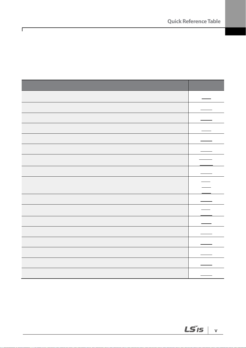
Quick Reference Table
I want to configure the inverter to start operating as soon as the power source
is applied.
I want to configure the motor’s parameters.
Something seems to be wrong with the inverter or the motor.
What are the recommended wiring lengths?
I want to apply PID control on my system.
What are the factory default settings for multi-function terminals?
I want to review recent fault trip and warning histories.
I want to change the inverter’s operation frequency using a potentiometer.
I want to install a frequency meter using an analog terminal.
I want to monitor the supply current to motor.
I want to operate the inverter using a multi-step speed configuration.
The cooling fan does not work.
I want to change the items that are monitored on the keypad.
I want to operate the inverter using a multi-step speed configuration.
The following table contains situations frequently encountered by users while working with
inverters. Refer to the typical and practical situations in the table to quickly and easily locate
answers to your questions.
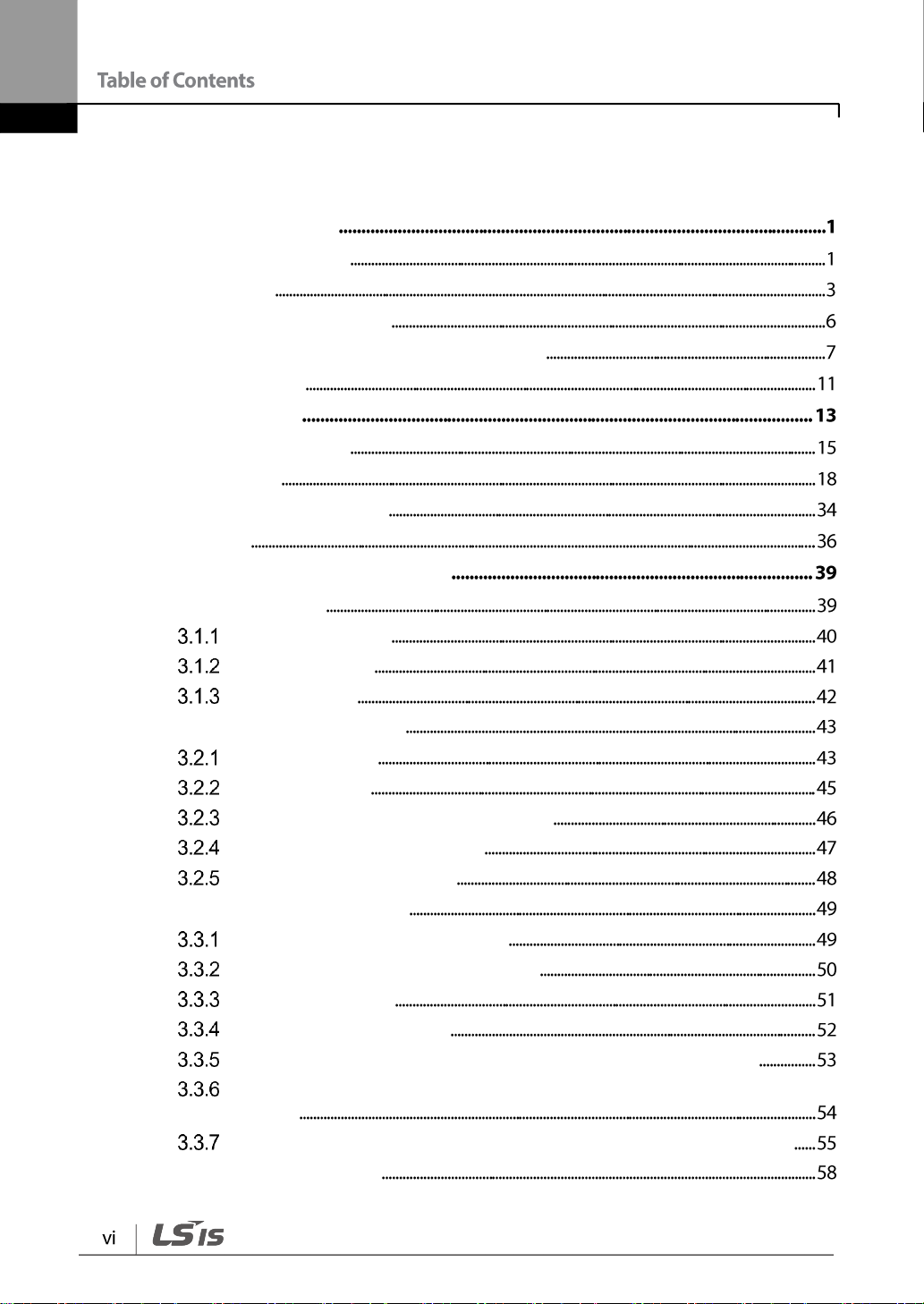
Table of Contents
1 Preparing the Installation
1.1 Product Identification
1.2 Part Names
1.3 Installation Considerations
1.4 Selecting and Preparing a Site for Installation
1.5 Cable Selection
2 Installing the Inverter
2.1 Mounting the Inverter
2.2 Cable Wiring
2.3 Post-Installation Checklist
2.4 Test Run
3 Learning to Perform Basic Operations
3.1 About the Keypad
About the Display
Operation Keys
Control Menu
3.2 Learning to Use the Keypad
Group Selection
Code Selection
Navigating Directly to Different Codes
Switching to a Different Code
Setting Parameter Values
3.3 Actual Application Examples
Acceleration Time Configuration
Frequency Reference Configuration
Frequency Setting
Initializing All Parameters
Frequency Setting (Keypad) and Operation (via Terminal Input)
Frequency Setting (External Potentiometer) and Operation (Terminal
Input)
Frequency Setting (Built-in Potentiometer) and Operation (Keypad)
3.4 Monitoring the Operation
Output Current Monitoring
Fault Trip Monitoring
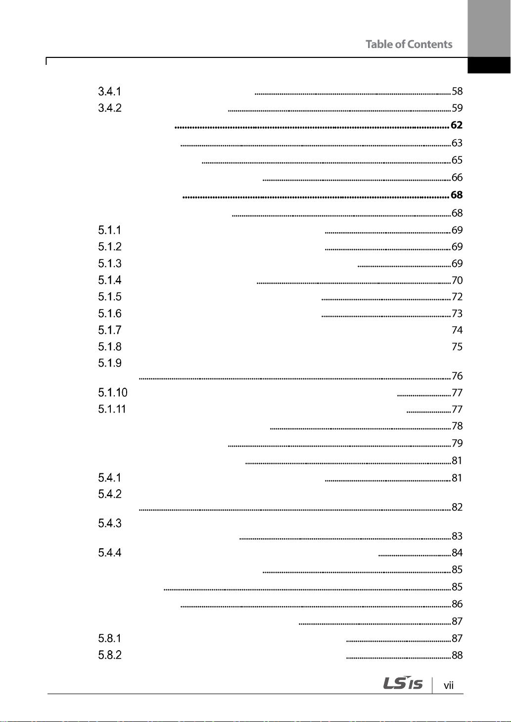
4 Control Block Diagram
4.1 Setting Frequency
4.2 Setting Run Command
4.3 Controlling Acc/Dec and V/F Voltage
5 Learning Basic Features
5.1 Setting Frequency Reference
Keypad as the Source (KeyPad-1 setting)
Keypad as the Source (KeyPad-2 setting)
Built-in Volume input (V0) 0 – 5 [V] as the Source
V1 Terminal as the Source
Input Current (Terminal I2) as the Source
Input Voltage (Terminal I2) as the Source
Frequency Reference Setting via Built-in Volume (V0) and I2 Terminal
Frequency Reference Setting via Built-in Volume (V0) and I2 Terminal
Frequency Reference Setting via Built-in Volume (V0) and V1 Terminal
Frequency Reference Setting via RS-485 Communication
Frequency Reference Setting via Digital Volume (Up-Down)
5.2 Holding Analog Command Frequency
5.3 Setting Multi-step Frequency
5.4 Command Source Configuration
The Keypad as a Command Input Device
Terminal Block as a Command Input Device (Fwd/Rev Run Commands)
Terminal Block as a Command Input Device (Run and Rotation
Direction Commands)
RS-485 Communication as a Command Input Device
5.5 Forward or Reverse Run Prevention
5.6 Power-on Run
5.7 Reset and Restart
5.8 Setting Acceleration and Deceleration Times
Acc/Dec Time Based on Maximum Frequency
Acc/Dec Time Based on Operation Frequency
Multi-step Acc/Dec Time Configuration
5.9 Acc/Dec Pattern Configuration
5.10 Stopping the Acc/Dec Operation
5.11 V/F(Voltage/Frequency) Control
Linear V/F Pattern Operation
Square Reduction V/F pattern Operation
User V/F Pattern Operation
Output Voltage Setting
5.12 Torque Boost
Manual Torque Boost
Auto Torque Boost
5.13 Stop Mode Setting
Deceleration Stop
Stop After DC Braking
Free Run Stop
5.14 Frequency Limit
Frequency Limit Using Maximum Frequency and Start Frequency
Frequency Limit Using Upper and Lower Limit Frequency Values
Frequency Jump
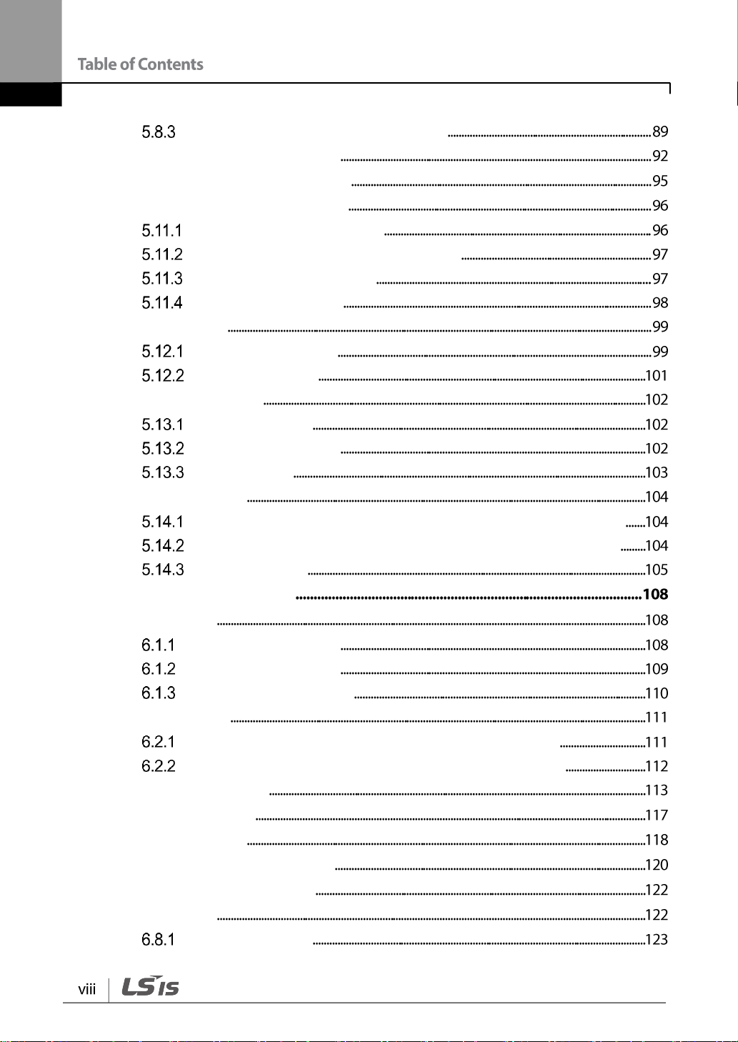
6 Learning Advanced Features
6.1 DC Braking
Stop After DC Braking
Start After DC Braking
DC Braking During Stop
6.2 Jog operation
Jog Operation 1-Forward Jog by Multi-function Terminal
Jog Operation 2-Fwd/Rev Jog by Multi-function Terminal
6.3 Up-down Operation
6.4 3-Wire Operation
6.5 Dwell Operation
6.6 Slip Compensation Operation
6.7 Simple Sensorless Control
6.8 PID Control
PID Basic Control
6.9 Energy Saving Operation
6.10 Speed Search Operation
6.11 Auto Restart Settings
6.12 Operational Noise Settings (carrier frequency settings)
6.13 2nd Motor Operation
6.14 Frequency Setting and 2nd Operation Mode Setting
6.15 Input Voltage Setting
6.16 Parameter Initialization
6.17 Parameter Lock
6.18 Voltage Trip Prevention During Deceleration
6.19 Brake Control
6.20 Analog Output
6.21 Digital Output
Multi-function Relay Output Terminal Settings
6.22 Draw Operation
6.23 Operation Mode Setting When Cooling Fan is Abnormal
6.24 Operation State Monitor
6.25 I/O Terminal Block State Monitor
6.26 Fault State Monitor
7 Learning Protection Features
7.1 Motor Protection
Electronic Thermal Motor Overheating Prevention (ETH)
Overload Early Warning and Trip
Stall Prevention
7.2 Inverter and Sequence Protection
Output Open-phase Protection
External Trip Signal
Inverter Overload Protection
Speed Command Loss
Dynamic Braking (DB) Resistor Configuration
Initial charging circuit trip(ROT)
8 RS-485 Communication Features
8.1 Communication Standards
8.2 Communication System Configuration
Communication Line Connection
Setting Communication Parameters
Setting Operation Command and Frequency
Command Loss Protective Operation
Parameter Group for Data Transmission
8.3 Communication Protocol
LS INV 485 Protocol
Modbus-RTU Protocol
8.4 Compatible Common Area Parameter
9 Table of Functions
9.1 Operation Group
9.2 Drive Group (PAR → dr)
9.3 Basic Function group (PAR→bA)
9.4 Expanded Function group (PAR→Ad)
9.5 Control Function group (PAR→Cn)
9.6 Input Terminal Block Function group (PAR→In)
9.7 Output Terminal Block Function group (PAR→OU)
9.8 Communication Function group (PAR→CM)
9.9 Application Function group (PAR→AP)
9.10 Protection Function group (PAR→Pr)
9.11 2nd Motor Function group (PAR→M2)
9.12 Config Mode group (PAR→CF)
10 Troubleshooting
10.1 Trips
Fault Trips
10.2 Troubleshooting Fault Trips
10.3 Troubleshooting Other Faults
11 Maintenance
11.1 Regular Inspection Lists
Daily Inspections
Annual Inspections
Bi-annual Inspections
11.2 Storage and Disposal
Storage
Disposal
12 Technical Specification
12.1 Input and Output Specification
12.2 Product Specification Details
12.3 External Dimensions (IP 20 Type)
12.4 Peripheral Devices
12.5 Fuse and Reactor Specifications
12.6 Terminal Screw Specification
12.7 Braking Resistor Specification
12.8 Continuous Rated Current Derating
12.9 Remote Keypad Option
Product Warranty
Index


1 Preparing the Installation
Check the product name, open the packaging, and then confirm that the product is free from
defects. Contact your supplier if you have any issues or questions about your product.
This chapter provides details on product identification, part names, correct installation and
cable specifications. To install the inverter correctly and safely, carefully read and follow the
instructions.
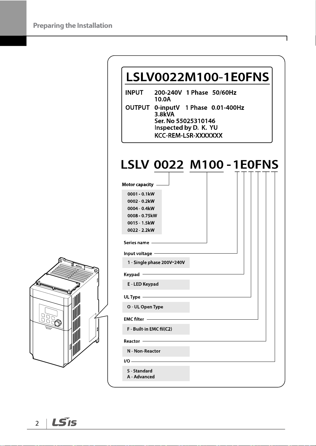
1.1 Product Identification
The M100 Inverter is manufactured in a range of product groups based on drive capacity
and power source specifications. Product name and specifications are detailed on the rating
plate. The illustration on the next page shows the location of the rating plate. Check the
rating plate before installing the product and make sure that the product meets your
requirements. For more detailed product specifications, refer to 12.1 Input and Output
Specification on page 242.
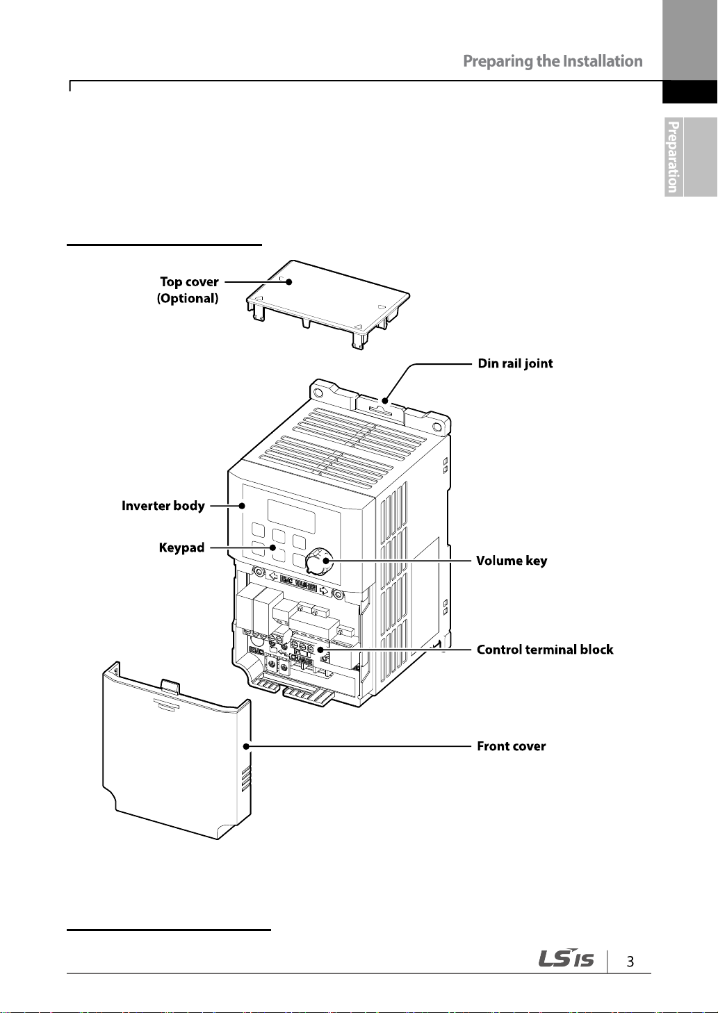
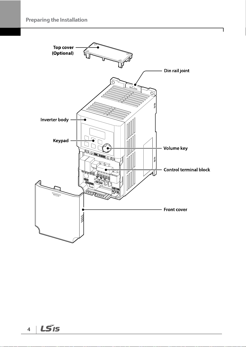
1.2 Part Names
The illustration below displays part names. Details may vary between product groups.
0.1~0.2 kW (Single Phase)
0.4~0.75 kW (Single Phase)
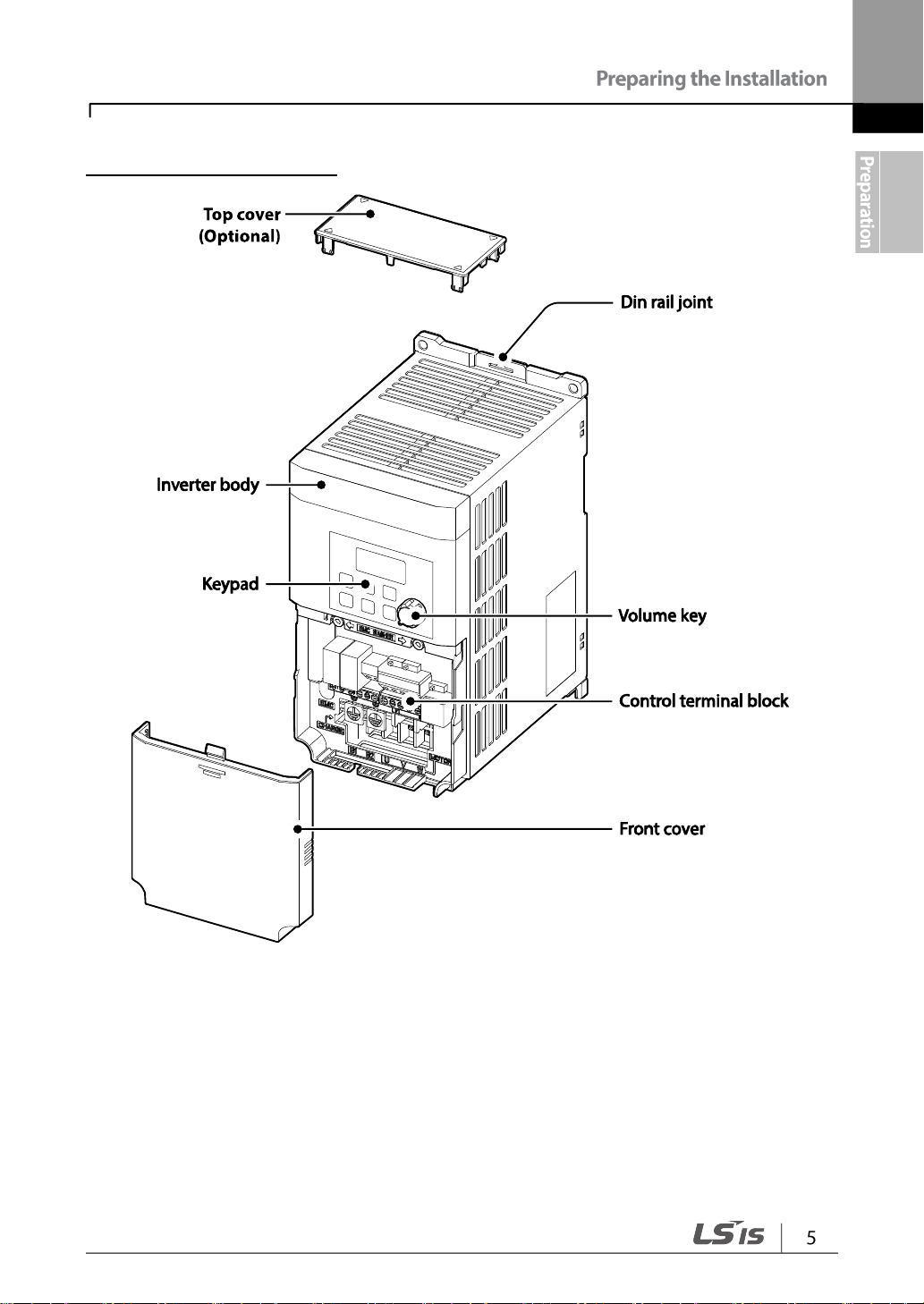
1.5~2.2 kW (Single Phase)
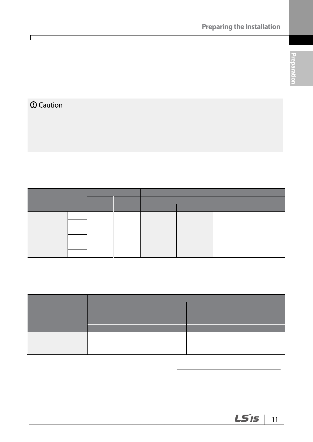
1.3 Installation Considerations
95% relative humidity (no condensation)
An environment free from corrosive or flammable gases, oil residue or
dust
Lower than 3,280 ft (1,000 m) above sea level/less than 1G (9.8
m/sec2)
Inverters are composed of various precision, electronic devices, and therefore the
installation environment can significantly impact the lifespan and reliability of the product.
The table below details the ideal operation and installation conditions for the inverter.
1) The ambient temperature is the temperature measured at a point 2” (5 cm) from the surface of the
inverter.
Do not allow the ambient temperature to exceed the allowable range while operating the
inverter.
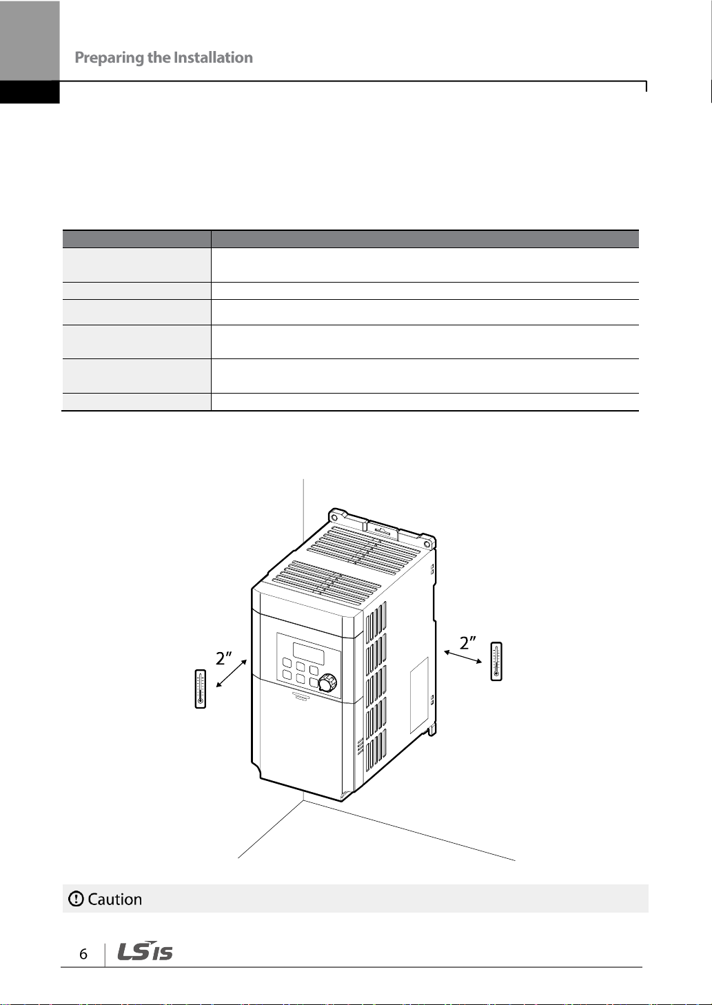
1.4 Selecting and Preparing a Site for Installation
When selecting an installation location consider the following points:
• The inverter must be installed on a wall that can support the inverter’s weight.
• The location must be free from vibration. Vibration can adversely affect the operation of
the inverter.
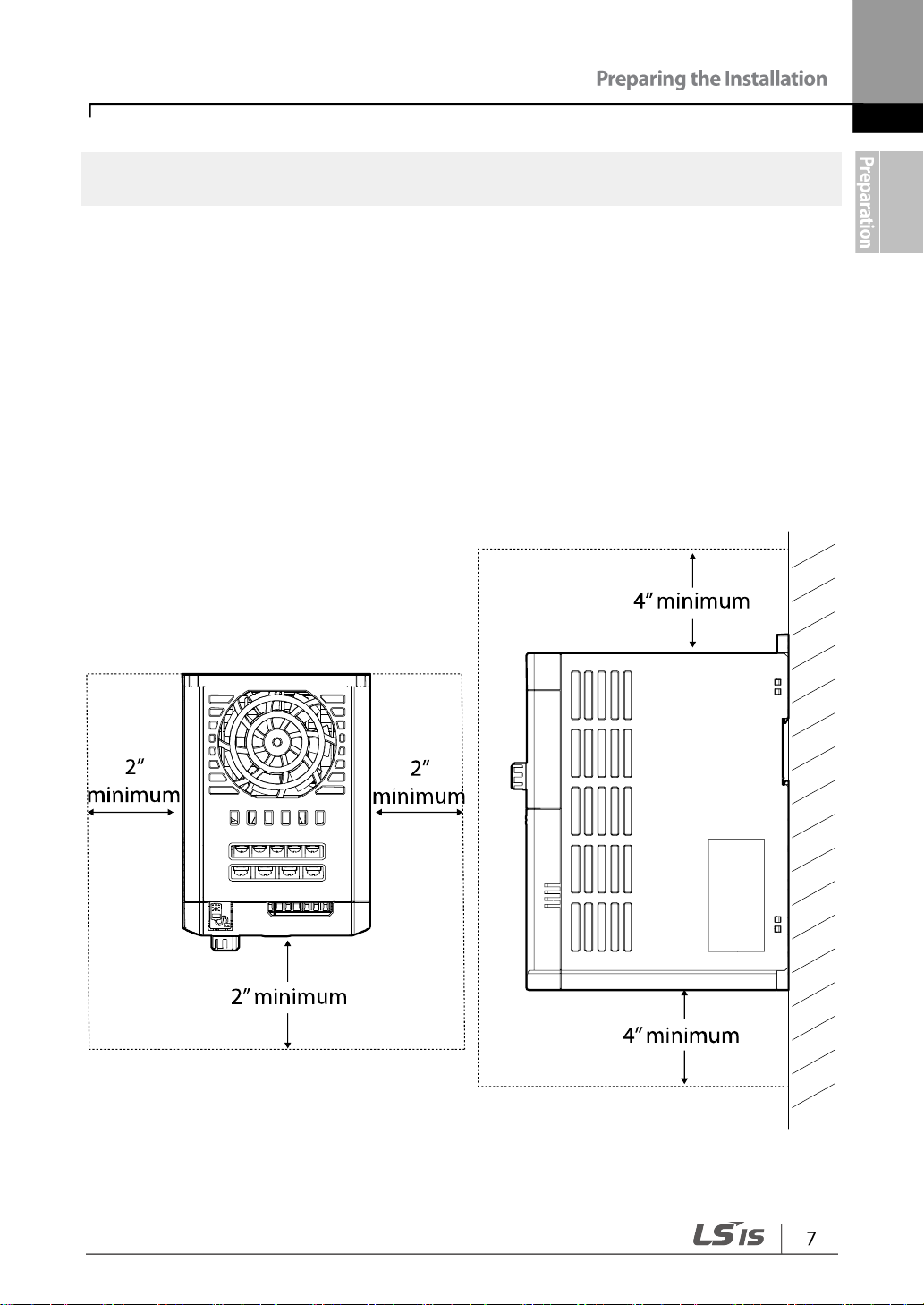
• The inverter can become very hot during operation. Install the inverter on a surface that
is fire-resistant or flame-retardant and with sufficient clearance around the inverter to
allow air to circulate. The illustrations below detail the required installation clearances.
• Ensure sufficient air circulation is provided around the inverter when it is installed. If the
inverter is to be installed inside a panel, enclosure, or cabinet rack, carefully consider the
position of the inverter’s cooling fan and the ventilation louver. The cooling fan must be
positioned to efficiently transfer the heat generated by the operation of the inverter.
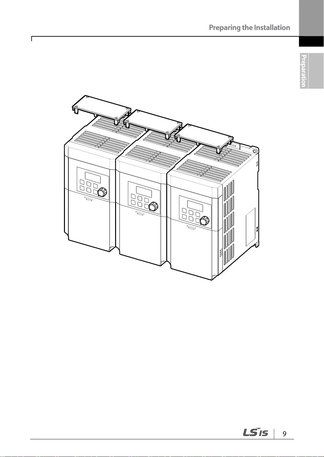
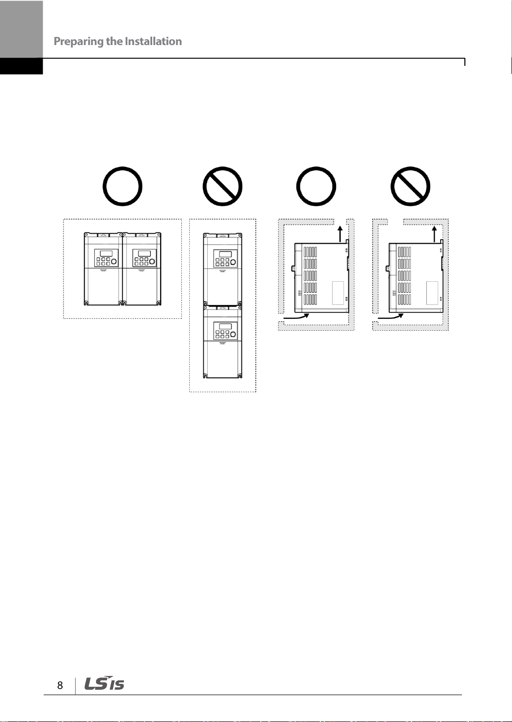
• If you are installing multiple inverters in one location, arrange them side by side and
remove their top covers (optional). The top covers MUST be removed for side-by -side
installations. Use a flat head screwdriver to remove the top covers.
• Keep the distance between inverters at least 0.1’’.
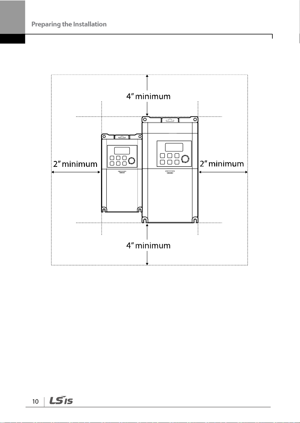
• If you are installing multiple inverters, of different ratings, provide sufficient clearance to
meet the clearance specifications of the larger inverter.
1.5 Cable Selection
• Wherever possible use cables with the largest cross-sectional area for mains power wiring,
to ensure that voltage drop does not exceed 2%.
• Use copper cables rated for 600V, 75℃ for power terminal wiring.
• Use copper cables rated for 300V, 75℃ for control terminal wiring.
Without Crimp Terminal
Connectors
With Crimp Terminal Connectors
(Bootlace Ferrule)
P1~P5/CM/VR/V1/I2
/AO/Q1/EG/241)
When you install power and signal cables in the terminal blocks, only use cables that meet
the required specification for the safe and reliable operation of the product. Refer to the
following information to assist you with cable selection.
Ground Cable and Power Cable Specifications
Signal (Control) Cable Specifications
1) There are no P4, P5, I2, A2, and C2 terminals on the standard I/O, and there are no Q1 and EG
terminals on the Advanced I/O. For more details, refer to 2.2 Cable Wiring Step 4 Control Terminal
Wiring on page 24.

2 Installing the Inverter
This chapter describes the physical and electrical installation methods, including mounting
and wiring of the product. Refer to the flowchart and basic configuration diagram provided
below to understand the procedures and installation methods to be followed to install the
product correctly.
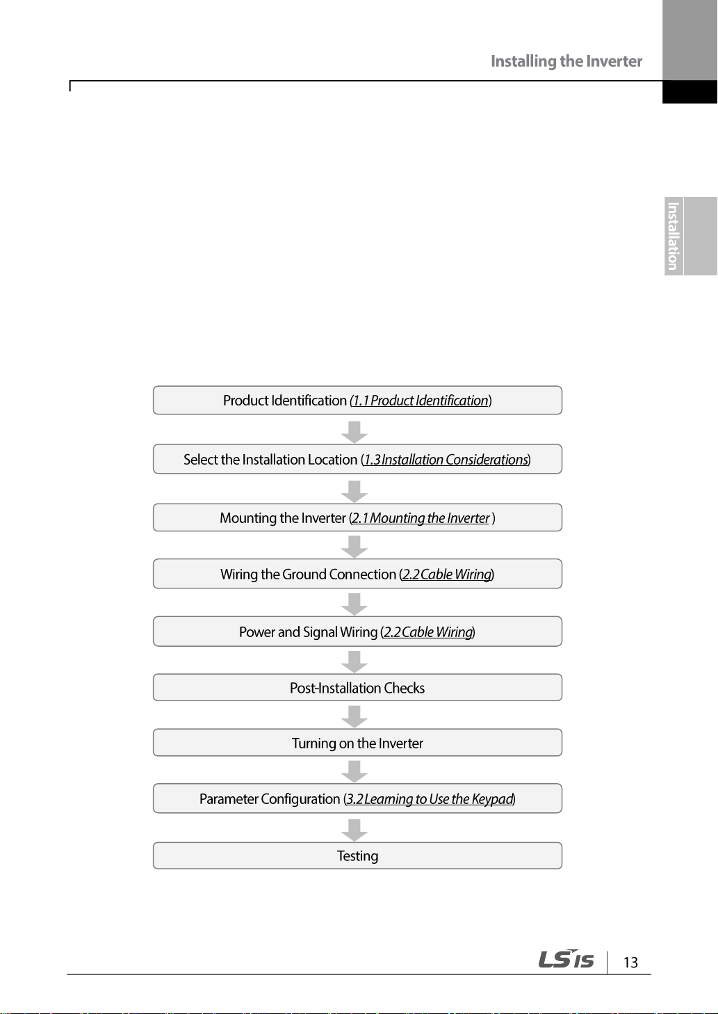
Installation Flowchart
The flowchart lists the sequence to be followed during installation. The steps cover
equipment installation and testing of the product. More information on each step is
referenced in the steps.
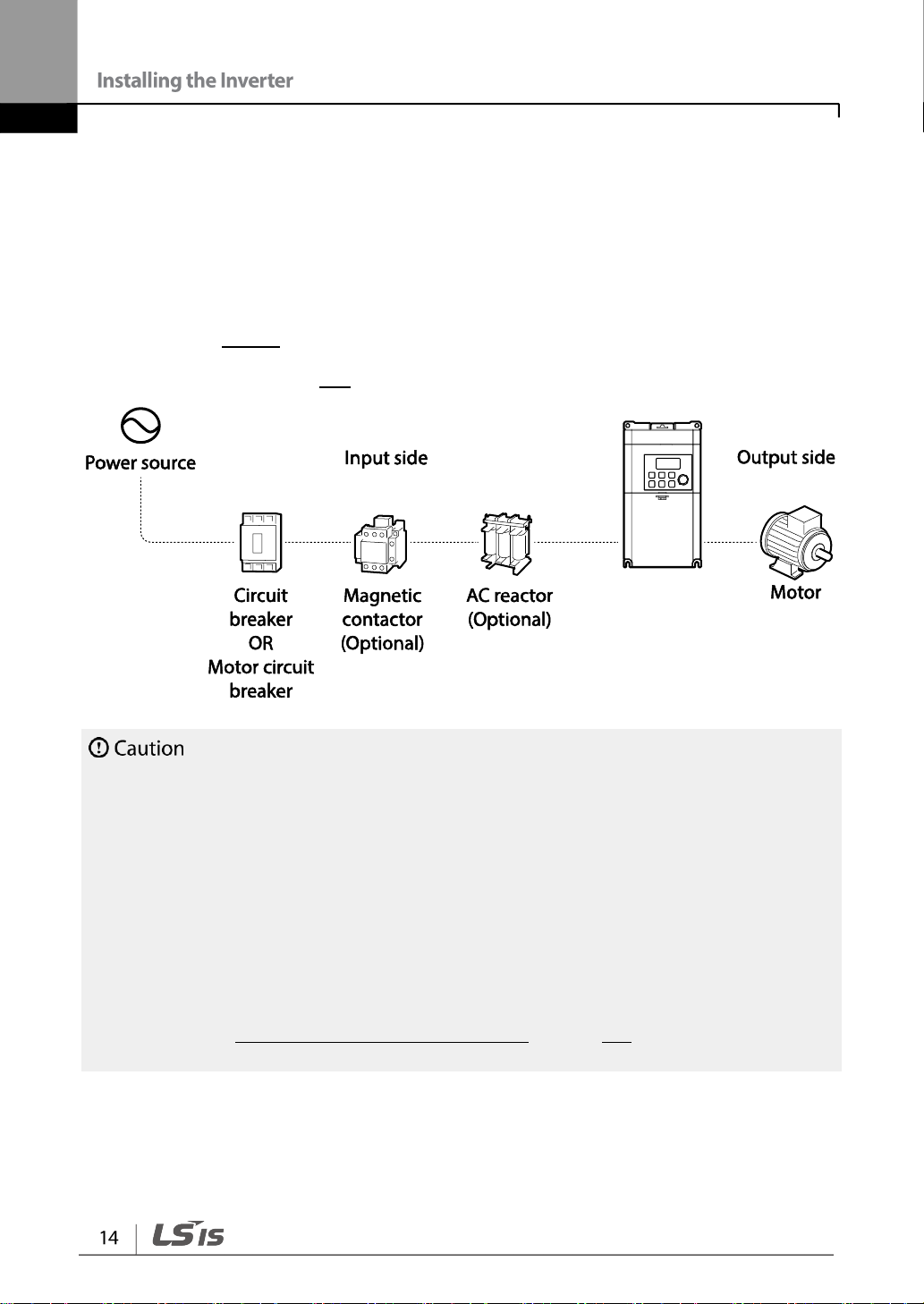
Basic Configuration Diagram
• Figures in this manual are shown with covers or circuit breakers removed to show a more
detailed view of the installation arrangements. Install covers and circuit breakers before
operating the inverter. Operate the product according to the instructions in this manual.
• Do not start or stop the inverter using a magnetic contactor, installed on the input power
supply.
• If the inverter is damaged and loses control, the machine may cause a dangerous situation.
Install an additional safety device such as an emergency brake to prevent these situations.
• High levels of current draw during power-on can affect the system. Ensure that correctly
rated circuit breakers are installed to operate safely during power-on situations.
• Reactors can be installed to improve the power factor. Note that reactors may be installed
within 30 ft (9.14 m) from the power source if the input power is 10 times over the inverter’s
power. Refer to 12.5 Fuse and Reactor Specifications on page 247 and carefully select a
reactor that meets the equipment.
The reference diagram below shows a typical system configuration showing the inverter
and peripheral devices.
Prior to installing the inverter, ensure that the product is suitable for the application (power
rating, capacity, etc). Ensure that all of the required peripherals and optional devices
(resistor brakes, contactors, noise filters, etc.) are available. For more details on peripheral
devices, refer to 0 Unit: mm (inches)
Peripheral Devices on page 247.

2.1 Mounting the Inverter
Mount the inverter on a wall or inside a panel following the procedures provided below.
Before installation, ensure that there is sufficient space to meet the clearance specifications,
and that there are no obstacles impeding the cooling fan’s air flow.
Select a wall or panel suitable to support the installation. Refer to 12.3 External Dimensions
(IP 20 Type) on page 245 and check the inverter’s mounting bracket dimensions.
1 Use a level to draw a horizontal line on the mounting surface, and then carefully mark
the fixing points
2 Drill the two upper mounting bolt holes, and then install the mounting bolts. Do not fully
tighten the bolts at this time. Fully tighten the mounting bolts after the inverter has been
mounted.
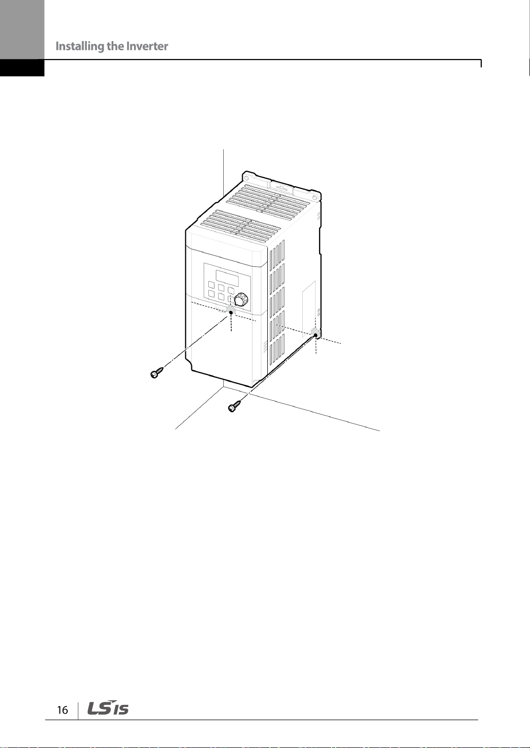
3 Mount the inverter on the wall or inside a panel using the two upper bolts, and then fully
tighten the mounting bolts. Ensure that the inverter is placed flat on the mounting
surface, and that the installation surface can securely support the weight of the inverter.
The quantity and dimensions of the mounting brackets vary based on frame size. Refer to 12.3
External Dimensions (IP 20 Type) on page 245 for detailed information about your model.
• Do not transport the inverter by lifting with the inverter’s covers or plastic surfaces. The
inverter may tip over if covers break, causing injuries or damage to the product. Always
support the inverter using the metal frames when moving it.
• Use an appropriate transport method that is suitable for the weight.
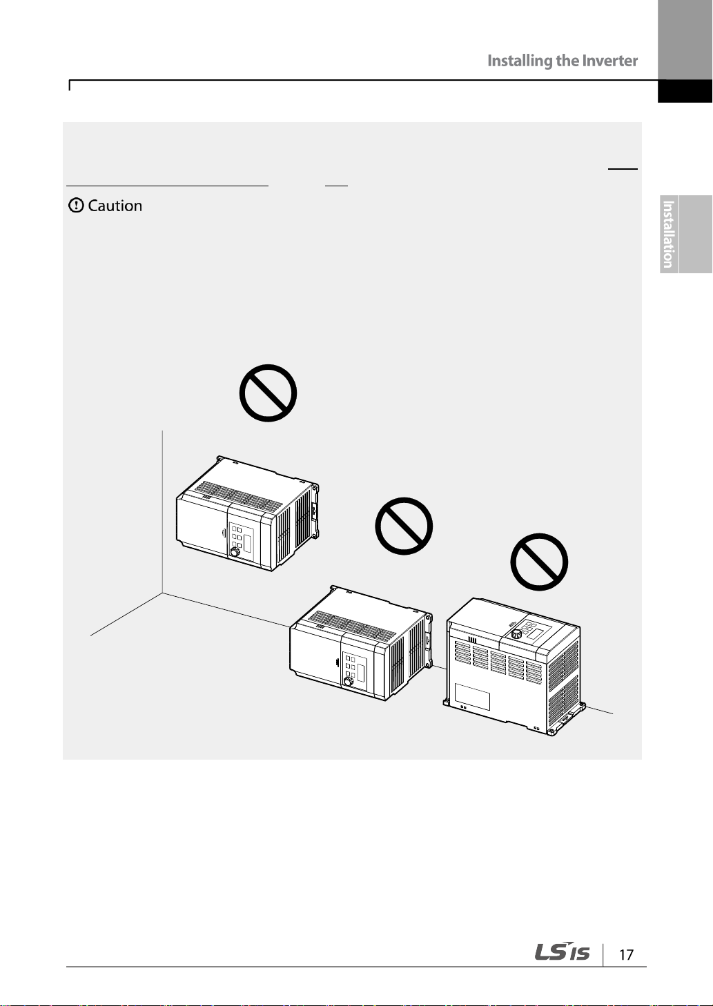
• Do not install the inverter on the floor or mount it sideways against a wall. The inverter
MUST be installed vertically, on a wall or inside a panel, with its rear flat on the mounting
surface.

2.2 Cable Wiring
• Install the inverter before carrying out wiring connections.
• Ensure that no small metal debris, such as wire cut-offs, remain inside the inverter. Metal
debris in the inverter may cause inverter failure.
• Tighten terminal screws to their specified torque. Loose terminal block screws may allow the
cables to disconnect and cause short circuit or inverter failure. Refer to 12.6 Terminal Screw
Specification on page 248 for torque specifications.
• Do not place heavy objects on top of electric cables. Heavy objects may damage the cable
and result in electric shock.
• The inverter’s power is supplied by the supply grounding system. The TT, TN, IT, and corner-
grounded systems are not suitable for this inverter.
• The inverter may generate direct current to the inverter’s protective ground cable. Only type
B Residual Current Devices (RCD) or Residual Current Monitors (RCM) can be installed.
• Use cables with the largest cross-sectional area, appropriate for power terminal wiring, to
ensure that voltage drop does not exceed 2%.
• Use copper cables rated at 600V, 75℃ for power terminal wiring.
• Use copper cables rated at 300V, 75℃ for control terminal wiring.
• Connect the control terminals separately from the power terminal wiring or high potential
circuit (200 V relay sequence circuit).
• Ensure that there are no control terminal shorts or improper wiring. Control terminal shorts or
improper wiring may damage the inverter or cause malfunction.
• Use a shielded cable while making wiring connections at the control terminal. Unshielded
cables may cause the inverter to malfunction due to interference. Use an STP cable if ground
connections must be installed.
• If you need to re-wire the terminals due to wiring-related faults, ensure that the inverter
keypad display is turned off and the charge lamp under the front cover is off before working
on wiring connections. The inverter may hold a high voltage electric charge long after the
power supply has been turned off.
Remove the control terminal cover, and then install the ground connection as specified.
Complete the cable connections by connecting an appropriately rated cable to the terminals
on the power and control terminal blocks.

Step1 Front Cover, Control Terminal Cover and Cable Guide
If you have installed the remote keypad, remove the plastic cover under the lower-right part of
the control terminal cover, and then connect the remote keypad signal to the RJ-45 connector.
The front cover must be removed to install cables.
1 Slide the front cover downward while pressing and holding the upper-center part of the
cover.
2 Remove the cover by lifting it upward from the bottom and moving it away from the
front of the inverter.

Step 2 Ground Connection
Class 3 grounding is required. Resistance to ground must be < 100Ω.
Install ground connections for the inverter and the motor by following the correct specifications to
ensure safe and accurate operation. Using the inverter and the motor without the specified
grounding connections may result in electric shock.
Remove the control terminal cover, and then follow the instructions below to install the
ground connection for the inverter.
3 Locate the ground terminal and connect an appropriately rated ground cable to the
terminals. Refer to 1.5 Cable Selection on page11 to find the appropriate cable
specification for your installation.
4 Connect the other ends of the ground cables to the supply earth (ground) terminal.

Step3 Power Terminal Wiring
• Tighten terminal screws to their specified torque. Loose terminal screws may allow the
cables to disconnect and cause short circuit or inverter failure. Over tightening terminal
screws may damage the terminals and cause short circuits and malfunctions.
• Use copper cables rated for 600V, 75℃ for power terminal wiring.
• Use copper cables rated for 300V, 75℃ for control terminal wiring.
• When making wiring connections at the power terminals, do not make a bi-wired connection
to a single terminal.
• Power supply cables must be connected to the R and T terminals. Connecting power
cables to the U, V, and W terminals will cause internal damage to the inverter. Connect
motors to the U, V, and W terminals. Phase sequence arrangement is not necessary.
• Appliquer des couples de marche aux vis des bornes. Des vis desserrées peuvent
provoquer des courts-circuits et des dysfonctionnements. Ne pas trop serrer la vis, car
cela risqué d’endommager les bornes et de provoquer des courts-circuits et des
dysfonctionnements. Utiliser uniquement des fils de cuivre avec une valeur nominale
de 600 V, 75 ℃ pour le câblage de la borne d’alimentation, et une valeur nominale de
300 V, 75 ℃ pour le câblage de la borne de commande.
• Ne jamais connecter deux câbles à une borne lors du câblage de l’alimentation.
• Les câblages de l’alimentation électrique doivent être connectés aux bornes R, T. Leur
connexion aux bornes U, V et W provoque des dommages internes à l’onduleur. Le
moteur doit être raccordé aux bornes U, V et W. L’arrangement de l’ordre de phase
n’est pas nécessaire.
The following illustration shows the terminal layout on the power terminal block. Refer to the
detailed descriptions to understand the function and location of each terminal before making
wiring connections. Ensure that the cables selected meet or exceed the specifications in 1.5
Cable Selection on page11 before installing them.

0.1~0.2 kW (Single Phase)
0.4–0.75 kW (Single Phase)
1.5-2.2 kW (Single Phase)

Power Terminal Labels and Descriptions
Mains supply AC power connections.
Brake resistor wiring connection.
3-phase induction motor wiring
connections.
• Use STP (Shielded Twisted Pair) cables to connect a remotely located motor with the
inverter. Do not use 3 core cables.
• Ensure that the total cable length does not exceed 165ft (50m).
• Long cable runs can cause reduced motor torque in low frequency applications due to
voltage drop. Long cable runs also increase a circuit’s susceptibility to stray capacitance
and may trigger over-current protection devices or result in malfunction of equipment
connected to the inverter.
• Voltage drop is calculated by using the following formula:
Voltage Drop (V) = [√3 X cable resistance (mΩ/m) X cable length (m) X current(A)] /
1000
• Use cables with the largest possible cross-sectional area to ensure that voltage drop is
minimized over long cable runs. Lowering the carrier frequency and installing a micro surge
filter may also help to reduce voltage drop.
Allowed Carrier Frequency
Do not connect power to the inverter until installation has been fully completed and the inverter is
ready to be operated. Doing so may result in electric shock.

• Power supply cables must be connected to the R and T terminals. Connecting power cables
to other terminals will damage the inverter.
• Use insulated ring lugs when connecting cables to R/T and U/V/W terminals.
• The inverter’s power terminal connections can cause harmonics that may interfere with other
communication devices located near to the inverter. To reduce interference the installation of
noise filters or line filters may be required.
• To avoid circuit interruption or damaging connected equipment, do not install phase-
advanced condensers, surge protection, or electronic noise filters on the output side of the
inverter.
• To avoid circuit interruption or damaging connected equipment, do not install magnetic
contactors on the output side of the inverter.
Step 4 Control Terminal Wiring
The illustrations below show the detailed layout of control wiring terminals, and control
board switches. Refer to the detailed information provided below and 1.5 Cable Selection
on page 11 before installing control terminal wiring and ensure that the cables used meet
the required specifications.
<Standard I/O>

Control Board Switches
NPN/PNP mode selection switch
Analog voltage/current input terminal (I2) selection switch
Terminating resistor selection switch
Connection of the remote keypad, Smart Copier, or RS 485
communication (Advanced IO)
Connectors
<Advanced I/O>

P1
P2
P3
CM
VR
V1
CM
AO
P24
Q1
EG
C1
A1
B1
NPN PNP
SW1
AO
RJ45
Remote
다기능 입력
아날로그 입력
아날로그 출력
24V전원
오픈 콜렉터 출력
릴레이 출력
P1
P2
P3
P4
P5
CM
VR
V1
CM
I2
AO
P24
NPN PNP
SW1
V I
SW2
RJ45
Remote/
485Com
ON OFF
SW3
종단저항
아날로그입력
다기능 입력
C1
A1
B1
C2
A2
아날로그 입력
아날로그 출력
24V전원
릴레이 출력
릴레이 출력
<Standard I/O>
<Advanced I/O>

Input Terminal Labels and Descriptions
Multifunction
terminal
configuration
Configurable for multi-function input terminals.
Factory default terminals and setup are as follows:
• P1: Fx
• P2: Rx
• P3: Emergency stop trip
• P4: Fault reset (RESET)
• P5: Jog operation command (JOG)
(P1–P3 are available for standard I/O.)
Common terminal for analog terminal inputs and
outputs.
Analog input
configuration
Potentiometer
frequency
reference input
Used to setup or modify a frequency reference
via analog voltage or current input.
• Maximum Voltage Output: 12V
• Maximum Current Output: 100mA,
• Potentiometer: 1–5kΩ
Voltage input for
frequency
reference input
Used to setup or modify a frequency reference
via analog voltage input terminal.
• Unipolar: 0–10V (12V Max.)
Voltage/current
input for
frequency
reference input
Used to setup or modify a frequency reference via
analog voltage or current input terminals.
Switch between voltage (V2) and current (I2)
modes using a control board switch (SW2).
V Mode :
• Unipolar: 0–10 V (12 V Max.)
I Mode :
• Input current : 4–20 mA

Output/Communication Terminal Labels and Descriptions
Used to send inverter output information to
external devices: output frequency, output
current, output voltage, or a DC voltage.
• Output voltage: 0–10 V
• Maximum output voltage/current: 10 V, 10
mA
• Factory default output: Output frequency
Multi-functional
(open collector)
Common ground contact for an open collector
(with external power source)
External 24 V
power source
Maximum output current: 50 mA
Sends out alarm signals when the inverter’s
safety features are activated (AC 250V <1A, DC
30V < 1A).
• Fault condition: A1 and C1 contacts are
connected (B1 and C1 open connection)
• Normal operation: B1 and C1 contacts are
connected (A1 and C1 open connection)
Sends out alarm signals when the inverter’s
safety features are activated (AC 250V <1A, DC
30V < 1A).
• Fault condition: A2 and C2 contacts are
connected
• Normal operation: A2 and C2 contacts are
open connection
RJ45
Remote keypad
signal line
Used to send or receive the remote keypad
(optional) signals.
RS-485 signal
line (Advanced
I/O)
Used to send or receive RS-485 signals. Refer
to 8 RS-485 Communication Features on page
173.

Preinsulated Crimp Terminal Connectors (Bootlace Ferrule)
Ensure that there is no debris entered inside the inverter.
Use preinsulated crimp terminal connectors to increase reliability of the control terminal
wiring. Refer to the specifications below to determine the crimp terminals to fit various cable
sizes.
* If the length (L) of the crimp terminals exceeds 0.5” (12.7mm) after wiring, the control terminal cover
may not close fully.
To connect cables to the control terminals without using crimp terminals, refer to the
following illustration detailing the correct length of exposed conductor at the end of the
control cable.

Step 5 PNP/NPN Mode Selection
• While making wiring connections at the control terminals, ensure that the total cable length
does not exceed 165ft (50m).
• Ensure that the length of any safety related wiring does not exceed 100 ft (30 m).
• Ensure that the cable length between a remote keypad and the inverter does not exceed 1
0ft (3.04 m). Cable connections longer than 10 ft (3.04 m) may cause signal errors.
• Use ferrite material to protect signal cables from electro-magnetic interference.
• Take care when supporting cables using cable ties, to apply the cable ties no closer than 6
inches from the inverter. This provides sufficient access to fully close the front cover.
• When making control terminal cable connections, use a small flat-tip screw driver (0.1in
wide (2.5mm) and 0.015in thick (0.4mm) at the tip).
When making control terminal cable connections, ensure that the inverter’s power is turned off.
The M100 inverter supports both PNP (Source) and NPN (Sink) modes for sequence inputs
at the terminal. Select an appropriate mode to suit requirements using the PNP/NPN
selection switch (SW1) on the control board. Refer to the following information for detailed
applications.

PNP Mode (Source)
Select PNP using the PNP/NPN selection switch (SW1). Note that the factory default
setting is NPN mode. CM is the common ground terminal for all analog inputs at the
terminal, and P24 is 24V internal source. If you are using an external 24V source, build a
circuit that connects the external source (-) and the CM terminal.
NPN Mode (Sink)
Select NPN using the PNP/NPN selection switch (SW1). CM is the common ground
terminal for all analog inputs at the terminal, and P24 is 24V internal source.

Step 6 Disabling the EMC Filter for Power Sources with Asymmetrical
Asymmetrical Grounding Connection
One
phase of a
delta
connectio
n is
grounded
Intermediate
grounding
point on one
phase of a
delta
connection
The end of
a single
phase is
grounded
A 3-phase
connection
without
grounding
• Do not activate the EMC filter if the inverter uses a power source with an asymmetrical
grounding structure, for example a grounded delta connection. Personal injury or death by
electric shock may result.
• Wait at least 10 minutes before opening the covers and exposing the terminal connections.
Before starting work on the inverter, test the connections to ensure all DC voltage has been
fully discharged. Personal injury or death by electric shock may result.
Grounding
An EMC filter prevents electromagnetic interference by reducing radio emissions from the
inverter. EMC filter use is not always recommended, as it increases leakage current. If an
inverter uses a power source with an asymmetrical grounding connection, the EMC filter
MUST be turned off.

Before using the inverter, confirm the power supply’s grounding system. Disable the EMC
filter if the power source has an asymmetrical grounding connection. Check the location of
the EMC filter on/off screw and attach the plastic washer to the screw under the control
terminal block.
Step 7 Re-assembling the Cover
Re-assemble the cover after completing the wiring and basic configuration.

2.3 Post-Installation Checklist
Installation
Location/Power
I/O Verification
Is the installation location appropriate?
Does the environment meet the inverter’s operating
conditions?
Does the power source match the inverter’s rated input?
Is the inverter’s rated output sufficient to supply the
equipment?
Is a circuit breaker installed on the input side of the
inverter?
Is the circuit breaker correctly rated?
Are the power source cables correctly connected to the
R/S/T terminals of the inverter?
(Caution: connecting the power source to the U/V/W
terminals may damage the inverter.)
Are the motor output cables connected in the correct
phase rotation (U/V/W)?
(Caution: motors will rotate in reverse direction if three
phase cables are not wired in the correct rotation.)
Are the cables used in the power terminal connections
correctly rated?
Is the inverter grounded correctly?
Are the power terminal screws and the ground terminal
screws tightened to their specified torques?
Are the overload protection circuits installed correctly on
the motors (if multiple motors are run using one inverter)?
Is the inverter separated from the power source by a
magnetic contactor (if a braking resistor is in use)?
Are advanced-phase capacitors, surge protection and
electromagnetic interference filters installed correctly?
(These devices MUST not be installed on the output side
of the inverter.)
After completing the installation, check the items in the following table to make sure that the
inverter has been safely and correctly installed.

Are STP (shielded twisted pair) cables used for control
terminal wiring?
Is the shielding of the STP wiring properly grounded?
If 3-wire operation is required, are the multi-function input
terminals defined prior to the installation of the control
wiring connections?
Are the control cables properly wired?
Are the control terminal screws tightened to their specified
torques?
Is the total cable length of all control wiring < 165 ft (100
m)?
Is the total length of safety wiring < 100 ft (30 m)?
Are optional cards connected correctly?
Is there any debris left inside the inverter?
Are any cables contacting adjacent terminals, creating a
potential short circuit risk?
Are the control terminal connections separated from the
power terminal connections?
Have the capacitors been replaced if they have been in
use for > 2 years?
Has the fan been replaced if it has been in use for > 3
years?
Has a fuse been installed for the power source?
Are the connections to the motor separated from other
connections?
STP (Shielded Twisted Pair) cable has a highly conductive, shielded screen around twisted
cable pairs. STP cables protect conductors from electromagnetic interference.

2.4 Test Run
After the post-installation checklist has been completed, follow the instructions below to test
the inverter.
1 Turn on the power supply to the inverter. Ensure that the keypad display light is on.
2 Select the command source.
3 Set a frequency reference, and then check the following:
• If V1 is selected as the frequency reference source, does the reference change
according to the input voltage at VR?
• If I2 (V)1) is selected as the frequency reference source, is the voltage/current
selector switch (SW2)
• If I2 (V)
1)
is selected as the frequency reference source, does the reference change
according to the input voltage at VR?
• If I2 (I)
• If I2 (I)
1)
is selected as the frequency reference source, is the voltage/current selector
switch (SW2)
1)
is selected as the frequency reference source, does the reference change
1)
set to current?
according to the input current?
4 Set the acceleration and deceleration time.
1)
set to voltage??
5 Start the motor and check the following:
• Ensure that the motor rotates in the correct direction (refer to the note below).
• Ensure that the motor accelerates and decelerates according to the set times, and
that the motor speed reaches the frequency reference.
1) Available only for models equipped with advanced I/O.

Verifying the Motor Rotation
1 On the keypad, set the drv (Frequency reference source) code in the Operation group
to 0 (Keypad).
2 Set a frequency reference.
3 Press the [RUN] key. Motor starts forward operation.
4 Observe the motor’s rotation from the load side and ensure that the motor rotates
counterclockwise (forward).
• Check the parameter settings before running the inverter. Parameter settings may have to
be adjusted depending on the load.
• To avoid damaging the inverter, do not supply the inverter with an input voltage that
exceeds the rated voltage for the equipment.
• Before running the motor at maximum speed, confirm the motor’s rated capacity. As
inverters can be used to easily increase motor speed, use caution to ensure that motor
speeds do not accidently exceed the motor’s rated capacity.


3 Learning to Perform Basic Operations
This chapter describes the keypad layout and functions. It also introduces parameter
groups and codes, required to perform basic operations. The chapter also outlines the
correct operation of the inverter before advancing to more complex applications. Examples
are provided to demonstrate how the inverter actually operates.
3.1 About the Keypad
The keypad is composed of two main components – the display and the operation (input)
keys. Refer to the following illustration to identify part names and functions.

About the Display
Displays current operational status and parameter
information.
LED flashes during parameter configuration.
LED turns on (steady) during an operation, and flashes
during acceleration or deceleration.
LED turns on (steady) during forward operation.
LED turns on (steady) during reverse operation.
The following table lists display part names and their functions.
The table below lists the way that the keypad displays characters (letters and numbers).

Operation Keys
Used to run the inverter (inputs a RUN command).
STOP: stops the inverter.
RESET: resets the inverter following fault or failure
condition.
Switch between codes, or to increase or decrease
parameter values.
Switch between groups, or to move the cursor during
parameter setup or modification.
Used to enter the parameter setting mode, apply the set
parameter, and enter the operation information screen
from the fault notice screen when a fault occurs.
Used to set the operation frequency.
The following table lists the names and functions of the keypad’s operation keys.
_

Control Menu
Configures basic parameters for inverter operation.
Configures parameters for basic operations. These
include jog operation, torque boost, and other
parameters.
Configures basic parameters, including motor-related
parameters and multi-step frequencies.
Configure acceleration or deceleration patterns and to
setup frequency limits.
Configures functions such as carrier frequency or speed
search.
Configures input terminal–related features, including
digital multi–functional inputs and analog inputs.
Configures output terminal–related features such as
relays and analog outputs.
Communication
(Communication)
Configures communication features for RS-485 or other
communication options.
※Available only for models equipped with advanced I/O.
Application
(Application)
Configures PID control–related sequences and
operations.
Configures motor or inverter protection features.
Secondary Motor
(2nd Motor)
Configures secondary motor related features.
※The secondary motor (M2) group appears on the keypad
only when one of the multi-function input terminals
(standard I/O model: In65-67, advanced I/O model: In65-
69) has been set to 12 (Secondary motor).
Configuration
(Configuration)
Configures various features such as parameter setting,
The M100 inverter control menu uses the following groups.

3.2 Learning to Use the Keypad
• ‘0.00’
1)
, the initial code of the Operation group, is displayed when
the inverter is turned on.
• ‘dr 0’, the initial code of the Drive (dr) group, is displayed.
• ‘bA 0’, the initial code of the Basic (bA) group, is displayed.
• ‘Ad 0’, the initial code of the Advanced (Ad) group, is displayed.
• ‘Cn 0’, the initial code of the Control (Cn) group, is displayed.
• ‘In 0’, the initial code of the Input Terminal, is displayed.
• ‘OU 0’, the initial code of the Output Terminal, is displayed.
• ‘CM 0’, the initial code of the Communication group (CM) is
displayed.
• Press the [MODE] key.
※ Available only for models equipped with advanced I/O.
Group Selection
※ Groups, except the Operation group, are not displayed on the group list and not
accessible as factory default to prevent parameter input error. To display and access all
groups, go to the OGr code in the Operation group and set the parameter to 1.
You can move between groups in only one direction.

• ‘AP 0’, the initial code of the Application (AP) group, is displayed.
• ‘Pr 0’, the initial code of the Protection (Pr) group, is displayed.
• ‘M2-0’, the initial code of the Secondary Motor group, is displayed.
• Press the [MODE] key.
※This group is available when the secondary motor function is enabled.
※To enable the secondary motor function, set one of the multi-function
input terminal’s codes (standard I/O model: In 65-67, advanced I/O
model: In 65-69) to I2 (2nd Motor).
• ‘CF 0’, the initial code of the Configuration (CF) group, is
displayed.
• Press the [MODE] key at the Configuration group, and then ‘0.00’
(the initial code of the Operation group) will be displayed.
1) You can set reference frequencies at the initial code of the Operation group. The initial code is set
to 0.00 as factory default. After you set the frequency reference, the set value will be displayed.

Code Selection
• ‘0.00’, the initial code of the Operation group, is displayed.
• ‘ACC’, the second code of the Operation group, will be displayed.
• ‘dEC’, the third code of the Operation group, will be displayed.
• ‘OGr,’ the last code of the Operation group will be displayed.
• Press the [] key again.
The initial code ‘0.00’ will be displayed again.
Press the [] key to switch between codes in the opposite direction.
Follow the example below to learn how to switch between codes. This example applies to
all groups whenever you would like to switch to a specific code number.
_

Navigating Directly to Different Codes
• ‘Ad 0’, the initial code of the Advanced (Ad) group, is displayed.
• The code often used for the group will be displayed as default. For
example, ‘24’ is displayed as a default code of the Ad group.
• The first digit will be flashing. This indicates the flashing value is
ready to be modified. Press the [] key to set the first digit to ‘2’.
• Press the [MODE] key. The cursor will move to the left and the
tenth digit will be flashing.
• Press the [] key to change ‘2’ to ‘1’.
• The code destination ‘12’ will be displayed.
The 12th code of the Advanced (Ad) group will be displayed.
This example applies to all groups except the Operation group.
The following example details navigating to code Ad12, from the initial code in the
Advanced group (Ad 0). This example applies to all groups whenever you would like to
navigate to a specific code number.

Switching to a Different Code
• The 1st code of the Advanced (Ad) group, is displayed.
• Press the [ENT] key until Ad12 is displayed.
The 12th code of the Advanced (Ad) group will be displayed.
In some instances, the code number increases or decreases by more than 1 when you press
the [] or [] key, as some codes have no assigned function or may not be accessible. This is
when a new function is required to be assigned. Refer to 9 Table of Functions on page 192 for
more information.
Example) When you switch the code of the Advanced group while the Ad24 (Frequency
upper/lower limit options) code is set to 0 (No), the Ad25 (Frequency upper limit) and Ad26
(Frequency lower limit) codes are not accessible.
When the Ad24 code is set to 1 (Yes), the Ad25 and Ad26 codes are accessible.
The following example details switching to code Ad 12 from Ad 1. This example applies to
all groups whenever you would like to switch to a specific code number.

Setting Parameter Values
• Select the group and code to setup and modify parameter
settings, and then press the [ENT] key.
• Each digit of the parameter value will be flashing. This indicates
the flashing values are ready to be modified.
Press the [] or [] key to move the cursor to the number that you
would like to modify and then press the [MODE] key.
• The parameter value will flash on the display.
Press the [ENT] key again to save the change.
A flashing number on the display indicates that the keypad is waiting for an input from the user.
Changes will be saved when the [ENT] key is pressed while the number is flashing. The setting
change will be canceled if you press any other key.
Enable or disable features by setting or modifying parameter values for different codes.
Directly enter setting values, such as frequency references, supply voltages, and motor
speeds. Follow the instructions below to learn to set or modify parameter values.

3.3 Actual Application Examples
• The initial code of the Operation group is displayed.
• ACC (acceleration time), the second code of the Operation group,
will be displayed.
• ‘5.0’ will be displayed and ‘0’ will be flashing.
• ‘5’ will be flashing. This indicates the flashing value ‘5’ is ready to
be modified.
• The parameter value is set to ‘6.0’.
• ‘0’ is displayed as the first digit and will be flashing.
• ‘16.0 ‘ will be displayed.
• ‘16.0’ will be flashing
1)
.
• Press the [ENT] key.
• Press the [ENT] key again.
ACC will be displayed and the acceleration time is set to ‘16.0’.
Acceleration Time Configuration
The following is an example demonstrating how to modify the ACC (Acceleration time) code
value (from 5.0 to 16.0) from the Operation group.
1) You can cancel setting the parameter by pressing any key except the [ENT] key while ‘16.0’ is
flashing.

Frequency Reference Configuration
• The initial code of the Operation group is displayed.
• The digit in the second decimal place becomes editable.
• Press the [] key until the digit in the second decimal place
reaches ‘5’.
• The cursor is moved to the left.
Press the [] key to set the first digit to ‘3’.
• The value will stop flashing. This indicates that the frequency
reference is set to ‘30.05’.
The M100 inverter keypad display can display up to 4 digits. However, 5-digit figures can be
used and are accessed by pressing the [MODE] key, to allow keypad input.
In step 7, you can cancel setting the parameter by pressing any key except the [ENT] key
while ’30.05’ is flashing.
The following is an example to demonstrate configuring a frequency reference of 30.05 (Hz)
from the first code in the Operation group (0.00).

Frequency Setting
• ‘Ad 0’, the initial code of the Advanced group, is displayed.
• The code value ‘24’ will be displayed.
• Press the [] key until the first digit reaches ‘7’.
• The code value ‘27’ will be displayed.
• ‘Ad27’ will be displayed.
• The 27th code value ‘0’ is displayed.
• Press the [] key until the code value reaches ‘1’.
The code value ‘1’ will flash and then the ‘Ad 27’ code will be
displayed.
The following is an example demonstrating how to modify the Ad 27 code value (from 0 to 1)
from the Advanced group.

Initializing All Parameters
• The initial code of the Configuration (CF) group is displayed
• The current value (‘1’) will be displayed.
• Press the [] key until ‘3’ is displayed.
• The code value ‘3’ will be displayed.
• ‘0’ will be displayed as the first digit and will be flashing. This
indicates the first digit is ready to be modified.
• Press the [] key until ‘9’ is displayed.
• ’93’ will be displayed.
• ‘CF93’ will be displayed.
• The parameter initialization will be in progress.
Press the [ENT] key. After the code value flashes, press the [ENT]
key again.
The code number is displayed again after the initialization is
complete.
The following example demonstrates parameter initialization using the 93rd code (CF 93) of
the Configuration group. Once executed, parameter initialization will delete all modified
values for all codes and groups.

Frequency Setting (Keypad) and Operation (via Terminal
• Ensure that ‘0.00’ is displayed.
• ‘0’, the last digit of ‘0.00’, will be flashing.
• Press the [MODE] key three times.
• ‘00.00’ will be displayed and its first digit will be flashing.
• Ensure that ‘10.00’ is displayed and then press the [ENT] key.
• When ‘10.00’ starts flashing, press the [ENT] key.
• When the frequency reference is set to 10.00 Hz, ‘10.00’ stops
flashing.
• Turn ON the switch located between the P1 (FX) terminal and CM
terminal. Refer to the Wiring Diagram below the table for
information about the switch.
• The RUN indicator light next to the inverter display will flash, the
FWD indicator will comes on steady. The current acceleration
frequency is displayed.
• When the frequency reference reaches (10 Hz), the display and
indicator appear as shown in the image on the right.
• Turn OFF the switch located between the P1 (FX) terminal and CM
terminal.
• The RUN indicator light next to the inverter display will flash again
and the current deceleration frequency is displayed.
• When frequency reference reaches 0 Hz, the RUN and FWD
indicator lights turn off, and the frequency reference (10.00 Hz) is
displayed again.
주파수
P1(FX)-CM
ON
OFF
10 Hz
Input)

The instructions in the table are based on the factory default parameter settings. The inverter
may not work correctly if the default parameter settings are changed after the inverter is
purchased. In such cases, initialize all parameters to reset the values to factory default
parameter settings before following the instructions in the table (refer to 6.166.16 Parameter
Initialization on page 138).
• Ensure that ‘0.00’ is displayed.
• Press the [] key four times.
• Ensure that the code is moved to Frq (Frequency reference
source).
• The frequency reference source is set to 0 (Keypad).
• Press the [] key three times.
• The frequency reference source is set to 3 (External
Potentiometer).
• Press the [ENT] key while ‘3’ flashes.
• When the frequency reference source has been set to external
potentiometer, the Frq code is displayed.
• Press the [] key four times to return to monitor the frequency
setting values.
• Adjust the external potentiometer to increase or decrease the
frequency reference to 10.00 Hz.
• The RUN indicator light next to the inverter display will flash, the
FWD indicator will comes on steady. The current acceleration
frequency is displayed.
• When the frequency reference reaches (10 Hz), the display and
indicator appear as shown in the image on the right.
• Turn OFF the switch located between the P1 (FX) terminal and CM
terminal.
Frequency Setting (External Potentiometer) and Operation
(Terminal Input)

• The RUN indicator light next to the inverter display will flash again
and the current deceleration frequency is displayed.
• When frequency reference reaches 0 Hz, the RUN and FWD
indicator lights turn off, and the frequency reference (10.00 Hz) is
displayed again.
M
R
T
U
V
W
G
P1(FX)
CM
VR
V1
CM
주파수
P1(FX)-CM
ON
OFF
10 Hz
The instructions in the table are based on the factory default parameter settings. The inverter
may not work correctly if the default parameter settings are changed after the inverter is
purchased. In such cases, initialize all parameters to reset the values to factory default
parameter settings before following the instructions in the table (refer to 6.16 Parameter
Initialization on page 138).
• Ensure that the ‘0.00’ is displayed.
• Press the [] key three times.
• Ensure that the code is moved to drv (Command source).
Frequency Setting (Built-in Potentiometer) and Operation
(Keypad)

• The command source is set to 1 (Inverter terminal).
• Ensure that the code value ‘0’ is displayed and then press the [ENT]
key.
• Press the [ENT] key once again when ‘0’ is flashing.
• When the frequency setting is changed to the [RUN] key of the
keypad, the drv code will be displayed.
• Ensure that the code is moved to Frq (Frequency reference source).
• The frequency reference source is set to 0 (Keypad).
• Press the [] key 2 times.
• Ensure that the frequency reference source is set to 2 (Built-in
Potentiometer), and then press the [ENT] key.
• Press the [ENT] key once again while ‘2’ is flashing.
• When the frequency reference source has been set to keypad
volume, the Frq code is displayed.
• Press the [] key four times to return to monitor the frequency
setting values.
• Adjust the built-in potentiometer to increase or decrease the
frequency reference to 10.00 Hz.
• The RUN indicator light next to the inverter display will flash, the
FWD indicator will comes on steady. The current acceleration
frequency is displayed.
• When the frequency reference reaches (10 Hz), the display and
indicator appear as shown in the image on the right.
• Press the [STOP/RST] key.
• The RUN indicator light next to the inverter display will flash again
and the current deceleration frequency is displayed.
• When frequency reference reaches 0 Hz, the RUN and FWD
indicator lights turn off, and the frequency reference (10.00 Hz) is
displayed again.

M
R
T
U
V
W
G
VR
V1
CM
키패드
주파수
RUN 키
10 Hz
STOP/RST 키

The instructions in the table are based on the factory default parameter settings. The inverter
may not work correctly if the default parameter settings are changed after the inverter is
purchased. In such cases, initialize all parameters to reset the values to factory default
parameter settings before following the instructions in the table (refer to 6.166.16 Parameter
Initialization on page 138).
3.4 Monitoring the Operation
• Ensure that the first code of the Operation group is selected, and
the code 30.00 (Command Frequency) is displayed.
• Press the [] or [] key until CUr is displayed.
• Ensure that the code is moved to CUr (Output current) for output
current monitoring.
Output Current Monitoring
The following example demonstrates how to monitor the output current in the Operation
group using the keypad.

• The inverter output current (5.0 A) will be displayed
• The cursor will move to the left.
You can use the dCL (DC link voltage monitor) and vOL (output voltage monitor) codes in the
Operation group in exactly the same way as shown in the example above, to monitor each
function’s relevant values.
• The OCt code is displayed when an over current trip fault has
occurred.
• Press the [ENT] key, and then press the [] or [] key.
• The operation frequency at the time of the fault (30.00 Hz) is
displayed.
• The output current at the time of the fault (5.0 A) is displayed.
Fault Trip Monitoring
The following example demonstrates how to monitor fault trip conditions in the Operation
group using the keypad.

• The operation status at the time of the fault is displayed. ACC on the
display indicates that the fault occurred during acceleration.
• Press the [STOP/RESET)] key.
The fault condition is cleared and the nOn code is displayed.
• You can use the dCL (DC link voltage monitor) and vOL (output voltage monitor) codes in
the Operation group in exactly the same way as shown in the example above, to monitor
each function’s relevant values.
• If multiple fault trips occur at the same time, a maximum of 3 fault trip records can be
retrieved as shown in the following example.


4 Control Block Diagram
주파수
설정
운전 지령
설정
가속 및 감속
V/F
전압 제어
PWM 전동기

4.1 Setting Frequency


4.2 Setting Run Command
입력 단자대
기능그룹
In85
디지털 입력 필터
P1
P2
P3
P4
P5
입력 단자대
기능그룹
In65~69
다기능 단자의
정, 역방향 운전 지령
선택
입력 단자대
기능그룹
In65~69
3-Wire 운전
확장 기능 그룹
Ad9
정, 역방향 회전 금지
운전 그룹
drv
운전 지령 방법
키패드지령
1,2
정회전금지
역회전금지
정,역 회전
운전지령
0,1
17
012
3
통신지령
0
3
012
※ P4,P5 및 In68,In69,
RS—485통신은 Advanced
I/O 탑재 모델만 사용
가능합니다.

4.3 Controlling Acc/Dec and V/F Voltage
운전 그룹
ACC
dEC
기본기능그룹
bA70~83
기본기능그룹
bA9
가감속 기준 주파수
가감속 시간
다단 가감속 시간
입력단자대
기능 그룹
In85
디지털 입력 필터
입력단자대
기능 그룹
In65~69
다기능 단자의
다단 가감속 선택
5,6,7
P1~P5
운전그룹
FrM
최대주파수
0
1
확장기능그룹
Ad1,Ad2
가감속 패턴
S자1
리니어0
확장기능그룹
Ad8
정지 방법 선택
012
직류 제동
프리런 정지
확장기능그룹
Ad14~17
직류제동
주파수, 제동량, 시간
확장기능그룹
Ad14~17
시동시 직류
제동
확장기능그룹
Ad20
드웰운전
Ad21
확장기능그룹
Ad25
주파수 상하한 선택
Ad26
0
1 ~ 7
운전지령
직류제동
제동량, 시간
드웰 주파수, 시간
기본기능그룹
bA7
V/F 패턴
012
2승저감
기본기능그룹
bA41~48
사용자 V/F 주파수, 전압
드라이브그룹
dr15
토크 부스트 선택
운전 그룹
Ftb
토크부스트량
0
1
rtb
자동
수동
리니어
사용자 V/F
운전 그룹
IOv
출력전압 조정
+
운전 그룹
MbF
dr19
기저, 시작 주파수
PWM
운전
정지
P1
P2
P3
P4
P5
설정주파수
드라이브그룹
※ P4,P5 및 In68,In69는
Advanced I/O 탑재 모델만
사용 가능합니다.


5 Learning Basic Features
Frequency
reference
source
Digital
Keypad digital frequency
Keypad digital frequency
setting 2
V1 terminal setting at the
terminal block : 0 –10 [V]
I2 ( I ) terminal setting at the
terminal block : 0–20 [mA]1)
I2 ( V) terminal setting at the
terminal block : 0–10 [V]1)
V0 setting + Terminal I2 ( I )1)
V0 setting + Terminal I2 ( V )1)
Up-down (Digital Volume) operation
This chapter describes the basic features of the M100 inverter. Refer to the following
sections to see detailed descriptions for each basic feature.
5.1 Setting Frequency Reference
The M100 inverter provides several methods to setup and modify a frequency reference for
an operation. The keypad, analog inputs [e.g., voltage (V1) and current/voltage (I2)1) signals],
or
RS-4851) communication can be used.
1) Available only for models equipped with advanced I/O.

Keypad as the Source (KeyPad-1 setting)
Frequency reference source
Frequency reference
source
You can modify the frequency reference by using the keypad and apply changes by
pressing the [ENT] key twice. To use the keypad as a frequency reference input source, go
to the Frq (Frequency reference source) code in the Operation group and change the
parameter value to 0. Input the frequency reference for an operation at the 0.00 (command
frequency) code in the Operation group, and then press the [ENT] key twice.
Keypad as the Source (KeyPad-2 setting)
You can use the [▲] and [▼] keys to modify a frequency reference.
To use this as a second option, set the keypad as the source of the frequency by going to
the Frq (Frequency reference source) code in the Operation group and changing the
parameter value to 1. Press the [ENT] key and then press the [▲] or [▼] key to modify the
frequency reference at the 0.00 (command frequency) code.
Built-in Volume input (V0) 0 – 5 [V] as the Source
You can modify the frequency reference by using the built-in volume (V0) dial. Go to the Frq
(Frequency reference source) code in the Operation group and change the parameter
value to 2, and then rotate the built-in volume (V0) dial. You can monitor the parameter
setting of the frequency reference at the 0.00 (command frequency) code in the Operation
group.

V0 input filter time
constant
0.00 – V0 input
max voltage
Frequency
corresponding to the
V0 input minimum
voltage
Frequency
corresponding to the
V0 input maximum
voltage
You can modify a frequency reference by setting the voltage inputs when using the V1
Frequency reference
source
V1 input filter time
constant
Frequency
corresponding to the
V1 input minimum
voltage
Frequency
corresponding to the
V1 input maximum
voltage
terminal or connecting the VR terminal to the V1 terminal.
V1 Terminal as the Source

Go to the Frq code in the Operation group and change the parameter value to 3.
You can monitor the parameter setting of the frequency reference at the 0.00 (command
frequency) code in the Operation group.
Load the 0 V–10 V signal between the V1 and CM terminals.
In 08 -11: Sets the input range and corresponding frequency for the forward (+) input
voltage (0 V–10 V) loaded to the V1 terminal.
Example) When the minimum forward (+) input voltage loaded to the V1 terminal is 2 V
while the frequency for the 2 V input is set to 10 Hz , and when the maximum input voltage
loaded to the V1 terminal is 8 V while the operation frequency is set to 50 Hz, the input
range is set as below:
You can connect the terminal wiring as shown below. Refer to the In 07 –11 features.

Input Current (Terminal I2) as the Source
Frequency reference
source
I input filter time constant
Frequency corresponding
to the I input minimum
current
I input min. current
– 20.00
Frequency corresponding
to the I input maximum
current
You can input the current to the control terminal block and set the command frequency by
changing the SW2 switch to I.1) Go to the Frq (Frequency reference source) code in the
Operation group and change the parameter value to 4, and then input the 0 – 20 mA
current to the I2 and CM terminals.
1) Available only for models equipped with advanced I/O.

Input Voltage (Terminal I2) as the Source
Frequency reference source
V input filter time constant
Frequency corresponding to
the V input minimum voltage
Frequency corresponding to
the V input maximum voltage
You can input the voltage to the control terminal block and set the command frequency by
changing the SW2 switch to V1). Go to the Frq (Frequency reference source) code in the
Operation group and change the parameter value to 5, and then input the 0–10 V voltage to
the I2 and CM terminals.
1) Available only for models equipped with advanced I/O.

Frequency Reference Setting via Built-in Volume (V0) and I2
Frequency reference source
V0 input filter time constant
Frequency corresponding to the V0 input
minimum voltage
Frequency corresponding to the V0 input
maximum voltage
I input filter time constant
Frequency corresponding to the I input
minimum current
Frequency corresponding to the I input
maximum current
Terminal
You can specify the current inputs for the built-in volume (V0) and I2 terminal as the main
reference and auxiliary reference respectively and enable the override feature.
1)
Change
the SW2 switch of the control terminal block and go to the Frq (Frequency reference source)
code in the Operation group and change the parameter value to 6.
1) Available only for models equipped with advanced I/O.
Override is a feature for entering the main reference value and the auxiliary reference value
simultaneously and applying the total value as a frequency reference. You can receive a
quick response via the main reference and accurately control via the auxiliary reference,
The built-in volume (V0) range is 0 – 5 V for the auxiliary reference and 0 –20 mA for the
main reference to use the override feature. You can set the main reference and auxiliary
reference values according to your operation condition.
Please refer to the following override operation settings.
1) Available only for models equipped with advanced I/O.
When the volume voltage is 2.5 V (2.5 Hz) and 12 mA (30 Hz) is supplied to the I2 terminal,
the inverter output frequency becomes 32.5 Hz.

Frequency Reference Setting via Built-in Volume (V0) and I2
Frequency reference
source
V0 input filter time constant
Frequency corresponding to the V0 input
minimum voltage
Frequency corresponding to the V0 input
maximum voltage
V input filter time constant
Frequency corresponding to the V input
minimum voltage
Frequency corresponding to the V input
maximum voltage
Terminal
You can specify the voltage inputs for the built-in volume (V0) and I2 terminal as the main
reference and auxiliary reference respectively and enable the override feature.
1)
Change
the SW2 switch of the control terminal block and go to the Frq (Frequency reference source)
code in the Operation group and change the parameter value to 7.
1) Available only for models equipped with advanced I/O.
1) Available only for models equipped with advanced I/O.
When the volume voltage is 2.5 V (2.5 Hz) and 5 V (30 Hz) is supplied to the I2 terminal,
the inverter output frequency becomes 32.5 Hz.

Frequency Reference Setting via Built-in Volume (V0) and
Frequency reference source
V0 input filter time constant
Frequency corresponding to the V0 input
minimum voltage
Frequency corresponding to the V0 input
maximum voltage
V1 input filter time constant
Frequency corresponding to the V1 input
minimum voltage
Frequency corresponding to the V1 input
maximum voltage
V1 Terminal
You can specify the voltage input for the built-in volume (V0) and V1 terminal as the main
reference and auxiliary reference respectively and enable the override feature, Go to the
Frq (Frequency reference source) code in the Operation group and change the parameter
setting to 8.
When the V0 voltage is 2.5 V (2.5 Hz) and 5 V (30 Hz) is supplied to the V1 terminal, the
inverter output frequency becomes 32.5 Hz.

Frequency Reference Setting via RS-485 Communication
Frequency reference
source
Communication
protocol setting
Frequency
reference source
You can control the inverter with upper-level controllers, such as PCs or PLCs, via RS-485
communication. Go to the Frq (Frequency reference source) code in the Operation group
and change the parameter setting to 9. This feature is available only for models equipped
with advanced I/O.
1) Available only for models equipped with advanced I/O.
※ For more information about RS-485 communication features, refer to 8 RS-485 Communication
Features on page 173.
Frequency Reference Setting via Digital Volume (Up-Down)
You can modify the command frequency by using the multi-function input terminal. Go to
the Frq (Frequency reference source) code in the Operation group and change the
parameter setting to 10.
Related code: In65–69, Ad64–67
※ For more information, refer to 6.3 Up-down Operation on page 113.

5.2 Holding Analog Command Frequency
Frequency reference source
Multi-function input terminal P1
function setting
Multi-function input terminal P2
function setting
Multi-function input terminal P3
function setting
Multi-function input terminal P4
function setting
Multi-function input terminal P5
function setting
Hold the command frequency by using multi-function input terminals.
1) You can only set 2, 3, and 8 for the Frq (Frequency reference source) parameter setting for models
equipped with standard I/O. For models equipped with advanced I/O, you can set 2–8.
2) For models equipped with standard I/O, you can set the parameter by In65–67 (Multi-function input
terminal P1–P3). You can use up to 3 multi-function input terminals for models equipped with
standard I/O. If you must use more than 3 multi-function input terminals, use models equipped with
advanced I/O.
You can hold the command frequency by using multi-function input terminals when the
parameter setting is 2–8 at the Frq (Frequency reference source) code in the Operation
group. Select a terminal to be used as an analog command frequency hold signal from P1–
P3 for standard I/O models or from P1–P5 for advanced I/O models, and then change the
parameter setting to 23 at the corresponding code (standard I/O model: In65–67, advanced
I/O model: In65–69).
It will operate as shown below when using the P5 terminal (In 69).
_

5.3 Setting Multi-step Frequency
Frequency
reference source
Multi-function input
terminal P3
function setting
Multi-function input
terminal P4
function setting
Multi-function input
terminal P4
function setting
1) For models equipped with standard I/O, you can set the parameter by In65–67 (Multi-function input
terminal P1–P3. You can use up to 3 multi-function input terminals for models equipped with
standard I/O. If you must use more than 3 multi-function input terminals, use models equipped with
advanced I/O.

Configure multi-step frequency 1–7 at the bA50–56 codes.
Set a terminal to use as the multi-step frequency reference among P1 –
P51). When you input the multi-step frequency reference via the P3 – P5
terminals1), set the parameter to 5–7 respectively at the In67–In69 codes in
the Input Terminal group.
Step 0 uses the frequency reference source set with the Frq and 0.00
frequency codes in the Operation group.
[An example of a multi-step operation]
1) For models equipped with standard I/O, you can set the parameter by In65–67 (Multi-function input
terminal P1–P3. You can use up to 3 multi-function input terminals for models equipped with
standard I/O. If you must use more than 3 multi-function input terminals, use models equipped with
advanced I/O.

5.4 Command Source Configuration
Operation by keypad, the Run
and Stop keys
FX: Forward
operation command
RX: Reverse
operation command
FX: Run, stop
RX: Reversed motor
direction
Operation by RS-485
communication1)
Motor rotation direction
selection1)
Various devices can be selected as command input devices for the M100 inverter. Input
devices available to select include keypad, multi-function input terminal, and RS-485
communication.
1) Available only for models equipped with advanced I/O.
The Keypad as a Command Input Device
The keypad can be selected as a command input device to send command signals to the
inverter. This is configured by setting the drv code to 0 in the Operation group. Press the
[RUN] or [STOP] keys on the keypad to start or stop an operation.
1) The rotation direction command by the dr20 setting is applied only when drv(Command source) is
set to 0. You can still display and set the dr20 setting when drv(Command source) is set to other
than 0.
You can press the [RUN] key to start an operation, and the [STOP/RST] key to decelerate
the motor and end the operation.
When you use the keypad as a command input device, you can set the motor rotation
direction at the dr20 code.
_

Rotation direction selection
Multi-function input terminal P1
function setting
Multi-function input terminal P2
function setting
Terminal Block as a Command Input Device (Fwd/Rev Run
Commands)
Multi-function terminals can be selected as a command input device. This is configured by
setting the drv code in the Operation group to 1. Select 2 terminals for the forward and
reverse operations,
When you use the multi-function input terminals P1 and P2 respectively for FX and RX
operation. Set In65 and In66 in the Input Terminal (In) group respectively to 0 and 1 at the
multi-function input terminals (standard I/O model: P1–P3, advanced I/O model: P1–P5).
Set the relevant code (standard I/O model: In65–In67, advanced I/O model: In65–In69) to 0
(FX) and 1 (Rx).
FX is a forward operation command and RX is a reverse operation command.
_

This application enables both terminals to be turned on or off at the same time, constituting a
stop command that will cause the inverter to stop operation.
Multi-function input
terminal P1 function setting
Multi-function input
terminal P2 function setting
Terminal Block as a Command Input Device (Run and
Rotation Direction Commands)
Multi-function terminals can be selected as a command input device. This is configured by
setting the drv code in the Operation group to 2. Select 2 terminals for operation commands
and rotation directions selection.
When you use the multi-function input terminals P1 and P2 respectively for FX and RX
operation. Set In65 and In66 in the Input Terminal (In) group respectively to 0 and 1 at the
multi-function input terminals (standard I/O model: P1–P3, advanced I/O model: P1–P5).
Set the relevant code (standard I/O model: In65–67, advanced I/O model: In65–69) to 0
(FX) and 1 (Rx).
FX (0): Assign a terminal for run command. When the RX terminal is set to OFF, the motor
is run in the forward direction.
RX (1): Assign a terminal for changing the rotation direction. When the RX terminal is set to
ON, the motor is run in the reverse direction.

Communication protocol
selection
RS-485 Communication as a Command Input Device
RS-485 communication can be selected as a command input device by setting the drv code
to 3 in the Operation group. This configuration uses upper level controllers such as PCs or
PLCs to control the inverter. This feature is only available for models equipped with
advanced I/O.
Set communication protocol, inverter station, and communication speed and run the motor
by RS-485 communication run command.
※For more details about RS-485 communication features, refer to 8 RS-485 Communication
Features on page 173.

5.5 Forward or Reverse Run Prevention
Forward and
reverse run
prevention
Do not set run
prevention.
Set forward run
prevention.
Set reverse run
prevention.
Use caution when operating the inverter with Power-on Run enabled as the motor will begin
rotating when the inverter starts up.
The rotation direction of motors can be configured to prevent motors from only running in
one direction. Set the Ad09 code in the Ad group to 0–2.
1) The rotation direction command by the dr20 setting is applied only when drv(Command source) is
set to 0. You can still display and set the dr20 setting when drv(Command source) is set to other
than 0.
5.6 Power-on Run
A power-on command can be setup to start an inverter operation after powering up, based
on terminal block operation commands (if they have been configured). To enable power-on
run, set the Ad10 code to 1 in the Ad group.
This feature is not disabled when the [RUN] key on the keypad or RS-485 communication is
selected as a command input device.

Use caution when operating the inverter with Reset and Restart enabled as the motor will begin
rotating when reset is operated via terminal block or keypad after a trip.
5.7 Reset and Restart
Reset and restart operations can be setup for inverter operation following a fault trip, based
on the terminal block operation command (if it is configured). Set the Pr08 code to 1.
This feature is not disabled when the [RUN] key on the keypad or RS-485 communication is
selected as a command input device.
_

5.8 Setting Acceleration and Deceleration Times
Acc/Dec reference
frequency
Acc/Dec Time Based on Maximum Frequency
Acceleration and deceleration time values can be set at the ACC and dEC codes in the
Operation group.
1) Changes based on the bA08 code parameter setting.
Acc/Dec time values can be set based on maximum frequency, not on inverter operation,
by setting the bA09 code to Acc/Dec and the reference frequency to 0.
Time scale for Acc/Dec time can be set at the bA08 code. If, for example, maximum
frequency is 60.00 Hz, the Acc/Dec times are set to 5 seconds, and the frequency reference
for operation is set at 30 Hz (half of 60 Hz), the time required to reach 30 Hz therefore is 2.5
seconds (half of 5 seconds).

Sets 0.01 second as the
minimum unit.
Sets 0.1 second as the
minimum unit.
Sets 1 second as the
minimum unit.
It is particularly useful that the time scale unit changes based on the max 5 digits of Acc/Dec
time value when more accurate Acc/Dec times are required due to load characteristics.
If, for example, the Acc/Dec time scale changes to 0.01 second, the maximum Acc/Dec
time will become 600.00 seconds. Refer to the following table.
Acc/Dec Time Based on Operation Frequency
1) Changes based on the bA08 code parameter setting.
Acc/Dec times can be set based on the time required to reach the next step frequency from
the existing operation frequency. To set the Acc/Dec time values based on the existing
operation frequency, set bA09 (acc/dec reference) in the bA group to 1 (delta frequency).
Loading…
- June 10, 2024
- LSIS
Table of Contents
- Safety Information
- Preparing the Installation
- Installing the Inverter
- Learning to Perform Basic Operations
- Technical Specification
- Read User Manual Online (PDF format)
- Download This Manual (PDF format)
www.lsis.com
LSLV-M100 AC Variable Speed Drive
Instruction Manual
The right choice for the ultimate yield!
LSIS strives to maximize your profits in gratitude for choosing us as your
partner.
0.1-2.2 kW [Single Phase 200V] AC Variable Speed Drive
LSLV-M100
Safety instructions
- Read this manual carefully before installing, wining, operating, servicing or inspecting this equipment.
- Keep this manual within easy reach for quick reference.
http://qr.lsis.com/e100/
Scan the QR Code and get the key use information! (Available also on the
product front cover.)
This operation manual is intended for users with basic knowledge of
electricity and electric devices.
LSLV- M 100 is the official name for the M 100 series inverters.
Visit our website at www.lsis.com for the complete user
manual.
Safety Information
1 1 Safety symbols in this manual
Danger|
—|—
Warning|
Caution|
1.2 Safety information
Danger
-
Do not open the cover of the equipment while it is on or operating. Likewise, do not operate the
inverter while the cover is open. Exposure of high voltage terminals or
charging area to the external
environment may result in an electric shock. Do not remove any covers or touch
the internal circuit
boards (PCBs) or electrical contacts on the product when the power is on or
during operation. Doing
so may result in serious injury, death, or serious property damage. -
Do not open the cover of the equipment even when the power supply to the inverter has been
turned off unless it is necessary for maintenance or regular inspection.
Opening the cover may result
in an electric shock even when the power supply is off. -
The equipment may hold charge long after the power supply has been turned off. Use a multi-meter to make sure that there is no voltage before working on the inverter, motor or motor cable.
Warning -
This equipment must be grounded for safe and proper operation.
-
Do not supply power to a faulty inverter. If you find that the inverter is faulty, disconnect the power supply and have the inverter professionally repaired.
-
The inverter becomes hot during operation. Avoid touching the inverter until it has cooled to avoid bums.
-
Do not allow foreign objects, such as screws, metal chips, debris, water, or oil to get inside the inverter. Allowing foreign objects inside the inverter may cause the inverter to malfunction or result in a fire.
-
Do not operate the inverter with wet hands. Doing so may result in electric shock.
-
Check the protection degree of circuits and equipment’s used in the inverter degree of circuit protection and the degree of equipment protection. The following connection terminals and components are electrical protection class O devices. The circuit is protected by the essential insulation and electric shock may occur if the insulation is done improperly. The same protection measures for electric cables must be taken when the using or installing the following components, or when you connect a cable to the following terminals or components. – Multi-function terminals: P1-P3, P4 (Advanced 1/0), PS (Advanced 1/0), CM -Analog terminal inputs and outputs: VR, V1, 12 (Advanced 1/0), AO, CM -Other terminal block connectors: Q1(Standard 1/0), EG (Standard /O), 24, A 1, B1,C1, A2 (Advanced 1/0), C2 (Advanced 1/0)
-Cooling fan -
This inverter is a protection class 1 product.
Caution -
Do not modify the interior workings of the inverter. Doing so will void the warranty.
-
The inverter is designed for 3-phase motor operation. Do not use the inverter to operate a single phase motor.
-
Do not place heavy objects on top of electric cables. Doing so may damage the cable and result in an electric shock.
Note/ Remarque
- Maximum allowed prospective short-circuit current at the input power connection is defined in IEC 60439-1 as 100 kA. Depending on the selected MCCB, the LSLV-M10O Series is suitable for use in circuits capable of delivering a maximum of 100 kA RMS symmetrical amperes at the drive’s maximum rated voltage. The following table shows the recommended MCCB for RMS symmetrical amperes.
Working Voltage| UTE100(E/N)| UTS150(N/H/L)| ABS33c| ABS53c| ABS63c|
ABS103c
—|—|—|—|—|—|—
240V(50/60Hz)| 50/65 kA| 65/100/150 kA| 30kA| 35kA| 35kA| 85kA
Preparing the Installation
2.1 Product Identification
LSLV 0022 M100 – 1E0ENS
Motor capacity| 0001-0.1kW| 0002-02kW| 0004-0.4kW| 0008-0.75kW| 0015- 1.5kW|
0022-2.2kW
Series name| M100
Input voltage| 1- Single phase 200V – 240V
Keypad| E – LED Keypad
ULType| 0 – UL Open Type
EMC Alter| F – Built-in EMC Filter(C2)
Reactor| N – Non-Reactor
VO| S – Standard| A -Advanced
2.2 Installation Considerations
| Items | Description |
|---|---|
| Ambient Temperature¹ | 14-122°F (-10-50°C) |
| Ambient Humidity | 95% relative humidity (no condensation) |
| Storage Temperature | -4-149°F (-20-65°C) |
| Environmental Factors | An environment free from corrosive or flammable gases, |
oil residue or dust
Altitude/Vibration| Lower than 3,280 ft (1,000 m) above sea loveless than 1G
(9.8 m/sec)
Air Pressure| 70106 kPa
- The ambient temperature is the temperature measured at a point 2″(5 cm)
from the surface of the inverter.
Caution
• Do not allow the ambient temperature to exceed the allowable range while
operating the inverter.
2.3 Selecting and Preparing a Site for Installation
- The inverter must be installed on a wall that can support the inverter’s weight.
- The location must be free from vibration. Vibration can adversely affect the operation of the inverter.
- The inverter can become very hot during operation. Install the inverter on a surface that is fireresistant or flame-retardant and with sufficient clearance around the inverter to allow air to circulate. The illustrations below detail the required installation clearances.
- Ensure sufficient air circulation is provided around the inverter when it is installed. If the inverter is to be installed inside a panel, endosome, or cabinet rack, carefully consider the position of the inverter’s cooling fan and the ventilation louver. The cooling fan must be positioned to efficiently transfer the heat generated by the operation of the inverter.
- If you are installing multiple inverters in one location, arrange them side by side and remove their top covers (optional). The top covers MUST be removed for side-by-side installations. Use a flat head screwdriver to remove the top covers.
- If you are installing multiple inverters, of different ratings, provide sufficient clearance to meet the clearance specifications of the larger inverter.
Note
-
The quantity and dimensions of the mounting brackets vary based on frame size.
Caution -
Do nontrans sport the inverter by lifting with the inverter’s covers or plastic surfaces. The inverter may tip over if covers break, causing injuries or damage to the product. Always support the inverter using the metal frames when moving it
-
Use an appropriate transport method that is suitable for the weight.
-
Do not install the inverter on the floor or mount it sideways against a wall. The inverter MUST be installed vertically, on a wall or inside a panel, with its rear flat on the mounting surface.
2.4 Cable Selection and Cable Wiring
■ Ground Cable and Power Cable Specifications
Load(kw)
| Ground| Power I/O
—|—|—
mm²
|
AWG
|
mm²
|
AWG
R/S/T
|
U/V/W
|
R/S/T
|
U/V/W
Single Phase
200V| 0.1, 0.2, 0.4,0.75|
3.5
|
12
|
2
|
2
|
14
|
14
1.5,2.2|
3.5
|
12
|
3.5
|
3.5
|
12
|
12
Note
-
Class 3 grounding is required. Resistance to ground must be < 1000.
Warning -
Install ground connections for the inverter and the motor by following the correct specifications to ensure safe and accurate operation. Using the inverter and the motor without the specified grounding connections may result in electric shock.
Caution -
Tighten terminal screws to their specified torque. Loose terminal screws may allow the cables to disconnect and cause short circuit or inverter failure. Over tightening terminal screws may damage the terminals and cause short circuits and malfunctions.
-
Use copper cables rated for 600V, 75°C for power terminal wiring.
-
Use copper cables rated for 300V,75C for control terminal wiring.
-
When making wiring connections at the power terminals, do not make a bi-wired connection to a single terminal.
-
Power supply cables must be connected to the R and Terminals. Connecting power cables to the U, V, and W terminals will cause internal damage to the inverter. Connect motors to the U, V, and W terminals. Phase sequence arrangement is not necessary.
■ Signal (Control) Cable Specifications
Terminal
|
Signal Cable
—|—
Without Crimp Terminal Connectors (Bare wire)| With Crimp Terminal Connectors
(Bootlace Ferrule)
mm²
| AWG| mm²|
AWG
P1-P5/CMVRN1/I2/AO/ Q1/EG/24¹
|
0.75
| 18| 0.5|
20
A1/B1/C1/A2/C2¹
|
1.0
| 17| 1.5|
15
- There are no P4, PS, 12,A2., and C2terminals on the standard VO, and there
are NoSQL and Terminals on the Advanced 1/0.
Caution
- Wherever possible use cables with the largest cross-sectional area for mains power wiring, to ensure that voltage drop does not exceed 2%.
- Use copper cables rated for 600V, 75°C for power terminal wiring.
- Use copper cables rated for 300V,75C for control terminal wiring.
Cable Wiring
- install the ground connection as specified. Complete the cable connections by connecting an appropriately rated cable to the terminals on the power and control terminal blocks.
Caution
- Install the inverter before carrying out wiring connections.
- Ensure that no small metal debris, such as wire cut-offs, remain inside the inverter. Metal debris in the inverter may cause inverter failure.
- Tighten terminal screws to their specified torque. Loose terminal block screws may allow the cables to disconnect and cause short circuit or inverter failure.
- Do not place heavy objects on top of electric cables. Heavy objects may damage the cable and result in electric shock.
- The inverter’s power is supplied by the supply grounding system. The TT, TN, IT, and comer grounded systems are not suitable for this inverter.
- The inverter may generate direct current to the inverter’s protective ground cable. Only type B Residual Current Devices (RCD) or Residual Current Monitors (RCM) can be installed.
- Use cables with the largest cross-sectional area, appropriate for power terminal wiring, to ensure that voltage drop does not exceed 2%.
- Use copper cables rated at 600V, 75C for power terminal wiring.
- Use copper cables rated at 300V, 75°C for control terminal wiring.
- Connect the control terminals separately from the power terminal wiring or high potential circuit (200 V relay sequence circuit).
- Ensure that there are no control terminal shorts or improper wiring. Control terminal shorts or improper wiring may damage the inverter or cause malfunction.
- Use a shielded cable while making wiring connections at the control terminal. Unshielded cables may cause the inverter to malfunction due to interference. Use an STP cable if ground connections must be installed.
- If you need to re-wire the terminals due to wiring-related faults, ensure that the inverter keypad display is turned off and the charge lamp under the front cover is off before working on wiring connections. The inverter may hold a high voltage electric charge long after the power supply has been turned off.
2.5 Terminal Screw Specification
■Input/output Terminal Screw Specification
Product(kW)|
Terminal screw Size
| Screw Torque (Kg.cm/Nm)
—|—|—
E| R| T| B1| B2| U| V| W| M3 -M3.5
(2.1∼5.0/0.2–0.5)
M4
(2.1∼8.0/0.2–0.8)
Single phase 200V| 0.1/0.2/0.4/0.75|
M3
1.5/2.2| M4| M3.5
■ Control Circuit Terminal Screw Specification
Terminal
| Terminal Screw Size|
Screw Torque(Kgf.cm/Nm
—|—|—
P1∼P5/CMNRN1 /12/A0/Q1 /EG/242)
| M2.6| 4.0/0.4
A1/B1/C1/A2/C2 ²
- P4,P5, 12, A2, and C2 terminals are unavailable when using the standard
1/0. Qi and EG terminals are unavailable when using the advanced VO.
Caution
• Apply rated torques to the terminal screws. Loose screws may cause short
circuits and malfunctions. Tightening the screw too much may damage the
terminals and cause short circuits and malfunctions.
Installing the Inverter
3.1 Basic Configuration Diagram

Caution
- Figures in this manual are shown with covers or circuit breakers removed to show a more detailed view of the installation arrangements. Install covers and circuit breakers before operating the inverter. Operate the product according to the instructions in this manual.
- Do not start or stop the inverter using a magnetic contactor, installed on the input power supply.
- If the inverter is damaged and loses control, the machine may cause a dangerous situation. Install an additional safety device such as an emergency brake to prevent these situations.
- High levels of current draw during power-on can affect the system. Ensure that correctly rated circuit breakers are installed to operate safely during power-on situations.
- Reactors can be installed to improve the power factor. Note that reactors may be installed within 30 ft. (9.14 m) from the power source if the input power is 10 times over the inverter’s power.
3.2 Peripheral Devices
■ Compatible Circuit Breaker, Leakage Breaker), Magnetic Contactor) and Motor
Circuit Breaker (MMS) Models (manufactured by LSIS)

■ Fuse and Reactor Specifications

Caution
- Use Class Hour RKS UL Listed Input Fuse and UL Listed Breaker Only. Seethe table above For the Voltage and Current rating of the fuse and the breaker.
Braking Resistor Specification
| Product(kW) | Resistance(Q) | Rated Capacity(W) |
|---|---|---|
| 1.5 | 60 | 300 |
| 2.2 | 50 | 400 |
•The standard for braking torque is 150% and the working rate (%ED) is 5%. If
the working rate is 10%, the rated capacity for braking resistance must be
calculated at twice the standard.
3.3 Power Terminal Labels and Descriptions
| Terminal Labels | Name | Descriptions |
|---|---|---|
| R/T | AC power input terminal | Mains supply AC power connections. |
| B1/B2(1.5kW-2.2kW) | Brake resistor terminals | Brake resistor wiring |
connections.
UN/W| Motor output terminals| 3-phase induction motor wiring connections.
Note
-
Use STP (Shielded Twisted Pair} cables to connect a remotely located motor with the inverter. Do not use 3 core cables.
-
Ensure that the total cable length does not exceed 165ft (50m).
-
Long cable runs can cause reduced motor torque in low frequency applications due to voltage drop. Long cable runs also increase a circuit’s susceptibility to stray capacitance and may trigger over-current protection devices or result in malfunction of equipment connected to the inverter.
-
Voltage drop is calculated by using the following formula:
Voltage Drop (V) = [83 X cable resistance (mms/m) X cable length (m) X
current(A)]/ 1000 -
Use cables with the largest possible cross sectional area to ensure that voltage drop is minimized over long cable runs. Lowering the carrier frequency and installing a micro surge filter may also help to reduce voltage drop.
| Distance | <165ft(50m) | <330ft(100m) | ≻330ft(100m) |
|---|---|---|---|
| Allowed Carrier Frequency | <15kHz | <5kHz | <2.5kHz |
warning
-
Do not connect power to the inverter until installation has been fully completed and the inverter is ready to be operated. Doing so may result in electric shock
Caution -
Power supply cables must be connected to the R and T terminals. Connecting power cables to other terminals will damage the inverter.
-
Use insulated ring lugs when connecting cables to /T and U/NW terminals.
-
The inverter’s power terminal connections can cause harmonics that may interfere with other communication devices located near to the inverter. To reduce interference the installation of noise filters or line filters may be required
-
To avoid circuit interruption or damaging connected equipment, do not install phase-advanced condensers, surge protection, or electronic noise filters on the output side of the inverter.
-
To avoid circuit interruption or damaging connected equipment, do not install magnetic contactors on the output side of the inverter.
3.4 Control Terminal Labels and Descriptions
- Terminal labels are the same for the both of Standard /O and Advanced /O.
- If a specified terminal is only available in Standard /O, it will be indicated as (Standard /o)
- If a specified terminal is only available in Advanced /O, it will be indicated as (Advanced VO).
Control Board Switches
| Switch | Description |
|---|---|
| SW1 | NPNPNP mode selection switch |
| SW2(Advanced I/O) | Analog voltage/current input terminal (12) selection switch |
| SW3(Advanced I/O) | Terminating resistor selection switch |
Connectors
| Connector | Description |
|---|---|
| RJ45Port | Connection of the remote keypad, Smart Copier, or RS 485 |
communication
(Advanced IO)
Input Terminal Labels and Descriptions
| Function | Label | Name | Description |
|---|
Multi function terminal
configuration| PI-P5| Multi-function
Input 1-5| Configurable for multi-function input terminals.
Factory default terminals and setup are as follows:
• P1:Fx
• P2:Rx
• P3: Emergency stop trip
• P4: Fault reset (RESET)
• P5: Jog operation command (JOG)
(Terminal P1∼P3 are available only in case of Standard VO.)
CM| Common
<Sequence| Common terminal for analog terminal inputs and output.
Analog input
configuration| VR| Potentiometer
frequency
reference input| Used to setup or modify a frequency reference via analog
voltage or current input.
• Maximum Voltage Output: 12V
• Maximum Current Output 100mA,
• Potentiometer. 1-5kO
V1| Voltage input
for frequency reference input| Used to setup or modify a frequency reference
via analog voltage input terminal.
• Unipolar. 0-10V(12V Max.)
| 12 (Advanced
VO)| Voltage/current
input for frequency
reference input| Used to setup or modify a frequency reference via analog
voltage or current input terminals.
Switch between voltage (V2) and current (I2) modes using a control board
switch (SW2}.
Mode: Unipolar. 0-10V(12V Max.)
Mode: linnet current :4-20 m4
—|—|—|—
Output/Communication Terminal Labels and Descriptions
| Function | Label | Name | Description |
|---|---|---|---|
| Analog output | AO | Voltage Output | Used to send inverter output information to |
external devices: output frequency, output current, output voltage, or a DC
voltage.
• Output voltage: 0-10V
• Maximum output voltage/current: 10V, 10 mA
• Factory default output: Output frequency
Digital output| 01
(Standard VO)| Multi-functional
(open collector)| DC 26 V, 100 mA or less
EG
(Standard VO)| Common| Common ground contact for an open collector (with
external power source)
24| External 24V
power source| Maximum Output current: 50 mA
A/IC1/BT| Fault signal output| Sends out alarm signals when the inverter’s
safety features are activated (AC250V <1A, DC30V < 1A)
.Fault condition: A1 and C1 contacts are connected (B1 and C1 open connection)
• Normal operation: B1 and C1 contacts are connected (Al and Cl open
connection)
A2/C2
(Advanced
1/0)| Fault signal output| Sends out alarm signals when the inverter’s safety
features are activated (AC250V <1A,DC 30V < 1A)
• Fault condition: A2 and C2 contacts are connected
• Normal operation: A2 and C2 contacts are open connection
Communication| RJ45| Remote keypad signal line| Used to send or receive the
remote keypad (optional) signals.
RS-485 signal line (Advanced /O)| Used to send or receive RS-485 signals.
3.5 Disabling the EMC Falter for Power Sources with Asymmetrical Grounding
• Before using the inverter, confirm the power supply’s grounding system.
Disable the EMC filter if the power source has an asymmetrical grounding
connection. Check the location of the EMC filter or/off screw and attach the
plastic washer to the screw under the control terminal block.

Learning to Perform Basic Operations
4.1 Operation Keys
- The following table lists the names and functions of the keypad’s operation keys
| Key | Name | Description |
|---|---|---|
| [RUN] key | Used to run the inverter (inputs a RUN command}. | |
| [STOP/RESET] key | $TOP: stops the inverter. |
RESET: resets the inverter following fault or failure condition.
| [▲]key, [▼]key| Switch between codes, or to increase or decrease parameter
values.
| [MODE/SHIFT] key| Switch between groups, or to move the cursor during
parameter setup or modification.
| (ENTER] key| Used to enter the parameter setting mode, apply the set
parameter, and enter the operation information screen from the fault notice
screen when a fault occurs.
| [Volume] key| Used to set the operation frequency.
4.2 Control Menu
• The M100 inverter control menu uses the following groups.
| Group | Display | Description |
|---|---|---|
| Operation | – | Configures basic parameters for inverter operation. |
| Drive | Configures parameters for basic operations. These include jog |
operation, torque boost, and other parameters.
Basic| | Configures basic parameters, including motor related parameters and
multi-step frequencies.
Advanced| | Configure acceleration or deceleration patterns and to setup
frequency limits.
Control| | Configures functions such as carrier frequency or speed search.
Input Terminal
(Input)| | Configures input terminal-related features, inducing digital multi
functional inputs and analog input
Output Terminal| | Configures output terminal-related features such as relays
and analog outputs.
Communication| | Configures communication features for RS-485 or other
communication options. Available only for models equipped with advanced I/O.
Protection| | Configures PID control-related sequences and operations.
Protection| | Configures motor or inverter protection features.
Secondary Motor| | Configures secondary motor related features.
The secondary motor (M2) group appears on the keypad only when one of the
multi-function input terminals (standard VO model: In65-67, advanced /O model:
in65-69) has been set to 12 (Secondary motor).
Configuration| | Configures various features such as parameter setting.
43 Table of Functions in operation group
- Groups, except the Operation group, are not displayed on the group list and not accessible as factory default to prevent parameter input error. To display and access all groups, go to the 0Gr code in the Operation group and set the parameter to 1 .
Dis play| Comm.
Address| Name| Setting Range| Initial
value| Papen*
—|—|—|—|—|—
0.00| Ohl FOO| Command frequency| 0.00-Maximum frequency [Hz]| 0.00| 0
ACC| Ohl F01| Acceleration time| 0.0-6000.0 [s]’)| 5.0| 0
Dec| OhlF02| Deceleration time| 10.0| 0
dry| OhlF03| Command source| 0| Keypad| 1| X
1| Fix/Rx-1
2| Fix/Rx-2
3| RS-485 communication4
Frq| Ohl F04| Frequency Setting method| 0| Keypad 1| 0| X
1| Keypad 2
2| V0:0-5 [V]
3| V1:0-10 [V]
4| 12(1): 0-20 [mA]4
5| 12(V):0-10[V]2
6| V0+12(1)4
7| V0+12 (V)2)
8| VO + V1
9| RS-485 communication’)
10| Up-down operation
Mown| Oh1F05| Motor selection| 0.1 – 0.1kW| 0.2 – 0.2kW| –| X
0.4- Osakwe| 0.75 – 0.75kW
1.5- 1.5kW| 22- 2.2kW
More)| Ohl F06| Rated motor current| 0.1 -150.0[A]| –| X
Miff| Oh1F07| Base frequency| 30.00-400.00[Hz]| 60.00| X
Form| Ohl F08| Maximum
frequency| 40.00 -400.00[Hz]| 60.00| X
10v| Ohl F09| Output voltage setting| 0, 170-264[V]| 0| X
Ftb| Ohl FOA| Forward boost| 0.0-20.01Tol| 4.0| X
rtb| Oh 1 FOB| Reverse boost| 0.0-20.0[%]| 4.0| X
Curb| Oh1FOC| Output current| –| –| –
rPM| Ohl FOD| Motor RPM| –| –| –
—|—|—|—|—|—
dell| Ohl FOE| Inverter DC voltage| –| –| –
vole, PG,
tOr,v1M,
12M’”| Ohl FOF| User select signal| vOL| Output voltage| vOL| –
POr| Output power
tOr| Output torque
v1 M| Analog V1 terminal input
12M| Analog 12 terminal input
nOn| OhlF10| Currently out of order| –| –| –
OGr| Ohl F 1 1| Open hidden groups| 0| Hide groups except for operation group|
|
1| Enable all groups
- The setting range varies depending on the set value of the bA 8 code.
- Available only for models equipped with advanced VO.
- The initial value varies depending on the motor capacity setting (MkW) and the value is set based on the 220/440 HGEN motor when shipping.
- Display infonnation can be selected at dr81 (Monitor item setting). Settings can be changed during the inverter operation.
Technical Specification
5.1 Input and Output Specification
| | | | | |
—|—|—|—|—|—|—
Model LSLV ■ ❑ ■ ■ M100-1EOFN ■| 1| 2| 4| 8
Applied motor| Heavy
load| HP| 0.125| 0.25| 0.5| 1.0| 2.0| 3.0
kW| 0.1| 0.2| 0.4| 0.75| 2.| 2.
Rated output| Rated capacity (kVA)| 0.3| 0.6| 0.95| 2.| 3.0| 5.
Rated current (A)| 0.8| 1.| 2.| 4.| 75| 10.0
Output frequency| 0-400Hz
Output voltage (V)| 3-phase 200-240V
Rated input| Working voltage (V)| Single phase 200-240Vac (15%-+10%)
Input frequency| 50-60Hz(±-5%)
Rated current (A)| 1.0| 2.| 4.| 7.| 14.| I 18.7
Weight(Ib/kg)| 1.46/0.66| 22/1| 3.2/1.45
5.2 External Dimensions
■ 0.1-2.2kW(Single Phase)

| Items | W1 | W2 | H1 | H2 | H3 | 1 H4 | D1 | A | B | 0 |
|---|---|---|---|---|---|---|---|---|---|---|
| 0001M100-1, | 85 | 75 | 135 | 1355 | 145 | 5 | 100 | 5 | 45 | 5. |
| 0002M100-1 | (3.) | (3.) | (5.) | (5.) | (6.) | (0.) | (4.) | (0.) | (0.) | (0.) |
| 0004M100-1, | 85 | 75 | 153 | 1535 | 163 | 5 | 123 | 5 | 45 | 5. |
| 0008M100-1 | (334) | (3.) | (6.) | (6.) | (6.) | (0.) | (5.) | (0.) | (0.) | (0.) |
| 0015M100-1, | 100 | 90 | 180 | 1805 | 190 | 5 | 140 | 5 | 45 | 45 |
| 0022M100-1, | (4.) | (4.) | (7.) | (7.) | (748) | (0.) | (6.) | (0.) | (0.) | (0.) |
Unit: mm (inches)
HEAD OFFICE
Address: LS Tower, 127, LS-or, Dongan-gu, Anyang-is,
Gye0nggi-D0, 431-848, Korea
+ Overseas Subsidiaries
1SIS(Dalian) Co., Ltd. Dalian, China
Address. No. 15, Alexei 3-Road, Economic and
Technical Development Zone, Dalian 116600, China
Tel 86-411-8730-7510/Fax 86-411-8730-7560
· 1$IS/(Wuxi) Co., Ltd. Wii, China
Address: No. 1, Laxing Road, Wu National High &New
Tech Industrial Development Area, Wu214028, Jiang5u, P.I.China
Tel 86-510-8534-6666-8005/ Fax 86-510-8534-4078
LS Hulked Electric(Hubel) Co., Ltd. Hubei, China
Address: No, 100, Tanisha Road, Tianjin District
Yichang City, Hubei Province, 443004, China
Tel 86-717-667-7339/Fax
86-717-667-7559
1$ VINA Industrial Systems Co. Ltd. Manioc, Vietnam
Address: Nguyen Khel, Dong Anh, Hanoi, Vietnam
Tel 84-46275-8055/ Fax 84-4-3882-0220
LSIS(ME) FE_ Dubai, U.A.E.
Address. 108 19-205, JAFZA View Tower, Jebet Ali Free Zone,
Dubai, United Arab Emirates
Tel 971-4-886-5360/ Fax 971-4-886-5361
LSIS Europe B.V. _Netherlands
Address: St. Floor, Tupolevlaan 48, 1119NZ.Schiphol-Rijk, The Netherlands
Tel 31-20-654-1420/Fax 31-20-654-1429
· 15Is Japan Co. Ltd. Tokyo, Japan
Address: Tokyo Club Building 13F, 2-6 Kasumigaseki 3-chome,
Chiyoda-cu, Tolly0, 100-0013
Tel 81-3-6268-8241 / Fax 81-3-6268-8240
1SIS USA Inc._ Chicago, U.S.A
Address: 980 Woodlands Pewee, Vernon Hills, IL 60061 USA4
Tel 800-891-2941 / Fax
800-891-2941
+ Overseas Branches
· 15Is Shanghai Office, China
Address: 32nd Floor, International Corporate City, No.3000
NorthZhongshan Road, Putout District, Shanghai, China, 200063
Tel:86-21-5237-9977/Fax :86-21-5237-7189| LSIS Beijing Office, China
Address Room 2306, Building B Landen Center, No.24 Middle Road
East 3rd Ring Road, Cha0yang District, Beijing, P.R China
Tel:86-10-5761-3127/ Fax 86-10-5761-3128
LSIS Guangzhou Office, China
Address. Room 1818-1820, Xin yuan Building.NO.898 Tianhe North Road, Tianhe
District Guangzhou, PR China
Tel: 86-20-8326-6784 / Fax 86-20-8326-6287
ISIS Qingdao Office, China
Address Room 200L Galaxy Building 29 Shan0ong Road, Sinan District
Qin9Dao, Shan0ong PR China
Tel 86-532-8501-6058 / Fax. 86-532-8501-6057
LSIS Chengdu Office China
Address. Room1710, 17/F Hummin Empire Plaza
NO.I Fu8in Road, Chengdu, P.R. China
Tel 86-28.8670-3200/ Fax 86-28-8670-3203
1SIS Shenyang Office, China
Address: Room 803, Hong yuan Building. 52 South Nanjing Road,
Hoping District, Shenyang PR. China
Tel.86-24-2321-9050 / Fax 86-24-8386-7210
ISIS Jinan Office, China
Address. Room 317, Chuangrhan Center, No. 201, Shanda Road, Livia District
Jinan, Shandong R China
Tel.86-531-8699-7826 / Fax: 86-531-8697-7628
LSIS Co., Ltd. Tokyo Office, Japan
Address Tokyo Club Building 13F, 2-6, Kasumigaseki 3-chome
Chiyoda-cu, Tokyo, 100-0013
Tel 81-3-6268-8241 /Fax .81-3-6268-8240
1SIS Co.. Ltd. Rep. Office, Vietnam
Address. Green Power – EVNHCMC 14th floor, 35 Ton Duc Thang
District 1, HCMC Viet Nam
Tel 84.28. 3823.7890/ Fax . 84 28. 3823.0996
ISIS Moscow Office, Russia
Address: 123610, Krasnopresnenskaya, nab.. 12, building L
office N10OS, Moscow, Russia
Tel.7-495-258-1466/1467 / Fax
7-495-258-1466/1467
• ISIS Jakarta Office, Indonesia
Address. APL TOWER lanate 10 unit 3, JI. Lethem S. Parma ka. 28
11470, Jakarta Barat, Indonesia
Tel 62-21-293-7614
—|—
· Disdaimer of Liability
LSIS has reviewed the information in this publication to ensure consistency
with the hardware and software described. However, LSIS cannot guarantee full
consistency, nor be responsible for any damages or compensation, since
variance cannot be preluded entirely. Please check again the version of this
publication before you use the product.
www.lsis.com
@LSIS Co., Ltd 2017 All Rights Reserved.
Read User Manual Online (PDF format)
Read User Manual Online (PDF format) >>
Download This Manual (PDF format)
Download this manual >>
Оптимальная компактная серия преобразователей частоты M100 идеальна для небольших насосов, вентиляторов, конвейерных установок.
Отличительные особенности:
- Встроенный фильтр ЭМС (C2)
- Встроенный потенциометр
- Компактные размеры
- Встроенный тормозной ключ для 1,5 — 2,2 кВт
- Встроенный интерфейс RS485
- Монтаж на DIN-рейку, установка бок о бок (2 мм между преобразователями)
Дополнительная информация:
Переход в раздел технической документации
Запросить дополнительную информацию и цены