
Продолжаю постить никому не интересные посты. Но мне очень удобно, когда все в одном месте, да и еще может кому поможет. По факту, ничего нового и уникального тут нет, инструкция стандартная, которую высылают при покупке на почту, без каких либо изменений и дополнений.
Как установить язык:
Настройка приложения—Пользователь—языки и ввод—язык
Что такое заводской пароль?
Пароль — 3368
Как использовать Apple carplay и Android auto?
Для carplay: только для iphone убедитесь, что на вашем iphone включена функция siri, затем сначала
подключите Bluetooth к вашему iPhone, а затем откройте приложение CarLink, чтобы использовать его, или подключитесь напрямую с помощью USB-кабеля. Для Android auto: Только для Android-смартфона загрузите приложение Android auto на свой мобильный
телефон, затем подключитесь с помощью USB-кабеля к нашему радио, затем откройте приложение
CarLink, чтобы использовать его.
После установки нашего радиоприемника управление рулевым колесом не работает, что вам нужно сделать?
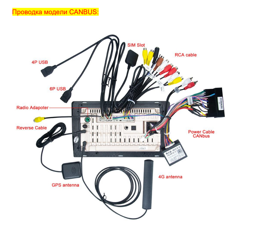
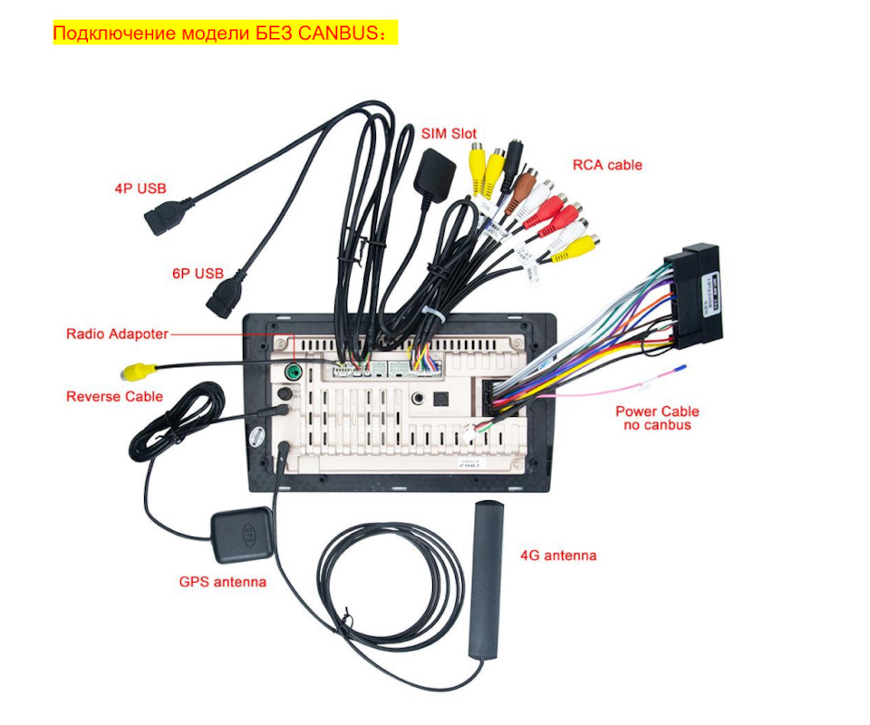
Подсоедините все кабели, как показано на фотографии выше. Если кабель питания не подключен к canbus, перейдите в функцию управления рулевым колесом, чтобы
узнать, как заставить кнопки SWC работать. Если кабель питания вашей модели подключен к canbus, не забудьте сначала подключить порт canbus, а затем сначала установить тип canbus, затем перейдите к настройке рулевого колеса, чтобы узнать
больше. Как установить тип canbus?(Если вы не знали, какой из них выбрать, свяжитесь с нами и
предоставьте фотографию canbus для подтверждения.)
У него белый разъем на кабеле canbus, пожалуйста, сначала проверьте, подключаете ли вы белый
разъем к автомагнитоле, затем перейдите в приложение настройки—заводские настройки—слово
пароля 3368—модель автомобиля
Как освоить функцию управления рулевым колесом?
Приложения—управление—Одна рука касается кнопки в меню, другая рука нажимает кнопку на рулевом
колесе после того, как вы ее настроите, она заработает. Пароль EKIY888 или EKIY123, скачайте видео по этой ссылке, чтобы узнать, как освоить кнопки
рулевого колеса.
oknavi-my.sharepoint.com/…pnVFlWVlXLIxUzUg?e=9l88TR
oknavi-my.sharepoint.com/…2hKW42OnoB_CuC_A?e=KDgRVC
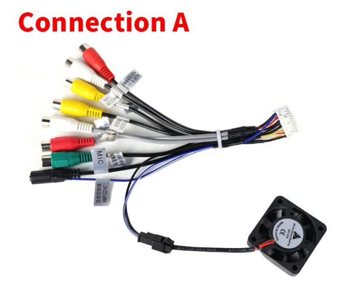
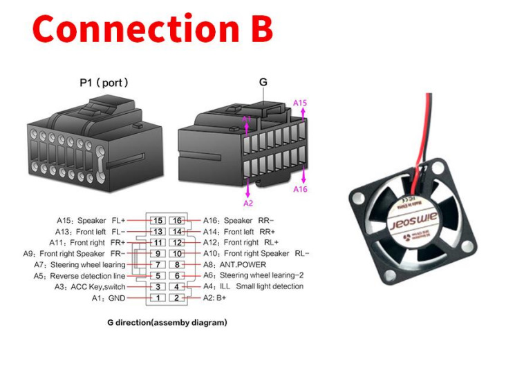
Как подключить вентилятор охлаждения?
Посмотрите на изображение ниже, чтобы узнать, как подключить вентилятор охлаждения, если ваш
вентилятор не может быть подключен напрямую как подключение A, затем проверьте подключение B, красный провод вентилятора к нашему основному кабелю питания ACC-провод в порту A3, черный — к
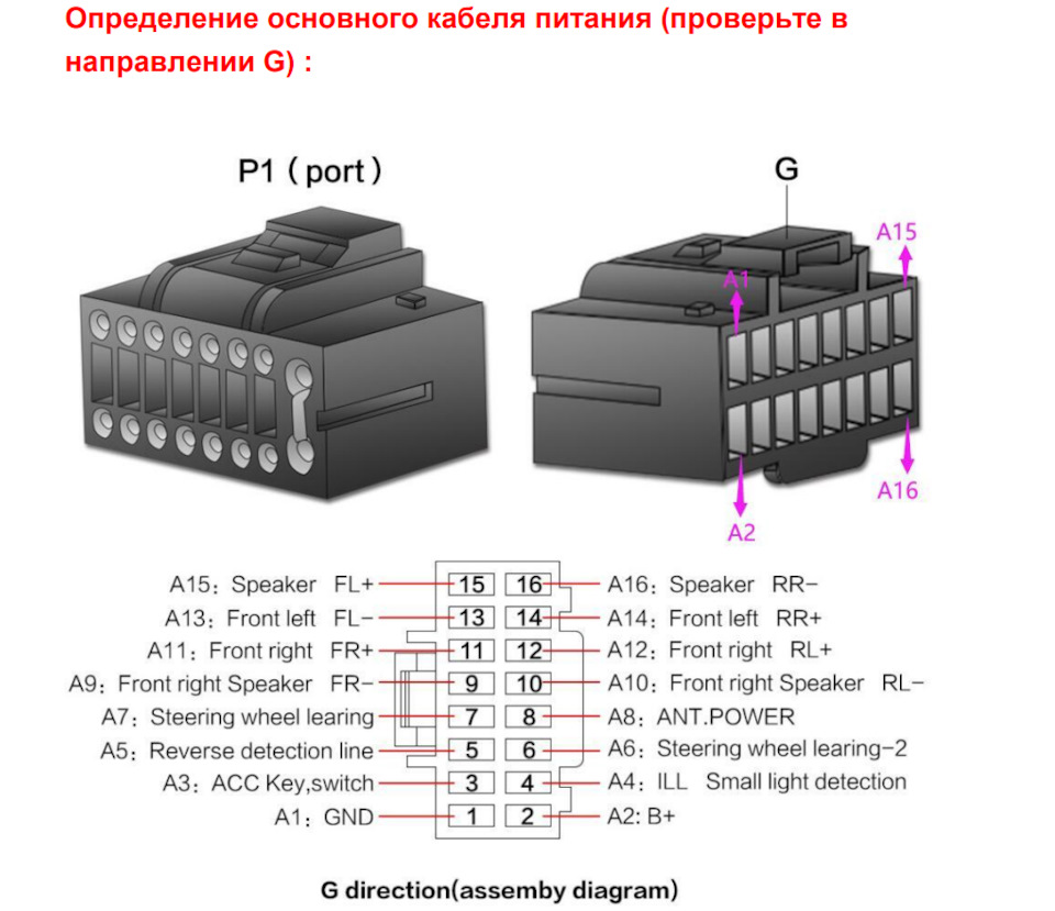
нашему основному кабелю питания GND-провод в порту A1. Определение основного кабеля питания
находится в соединении B, пожалуйста, проверьте. По любому вопросу, не стесняйтесь обращаться к
нам для решения. После подключения, если вентилятор не может работать, перейдите в настройки
устройства-устройство-звук -ВКЛЮЧЕНИЕ/ВЫКЛЮЧЕНИЕ усилителя-ВКЛ.
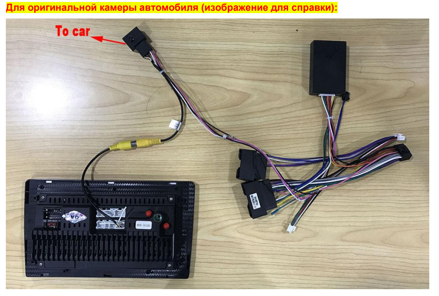
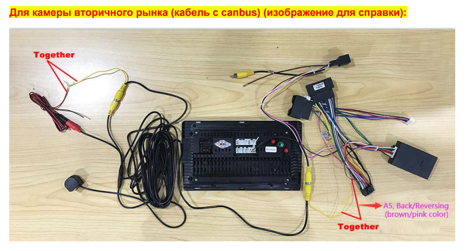
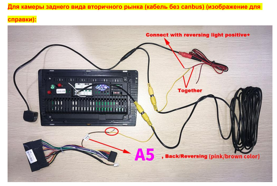
Как подключить камеру заднего вида?
Перейдите в приложение настройки устройства— заводские настройки—пароль 3368—Формат видео
заднего вида HD — AHD или TVI (если вы используете нашу подарочную AHD-камеру по умолчанию, установите ее на AHD, если вы используете оригинальную камеру вашего автомобиля или другую
камеру, которая не является AHD-камерой, то установите ее на
TVI)

AUDIO VIDEO SURROUND RECEIVER
KR-V888D
KR-V888D (En/T)
1
INSTRUCTION MANUAL
KENWOOD CORPORATION
Preparations
Operations
About the supplied remote control . . .
Compared to standard remote controls, the remote control supplied with this receiver has several
operation modes. These modes enable the remote control to perform on screen operations and control
other audio/video components. In order to effectively use the remote control it is important to read the
operating instructions and obtain a proper understanding of the remote control and how to switch its
operation modes (etc.).
Using the remote control without completely understanding its design and how to switch the operation
modes may result in incorrect operations.
B60-3017-10 CH (T) WS
98/12 11 10 9 8 7 6 5 4 3 2 1 97/12 11 10 9 8 7 6 5 4 3
Remote Control
Other

Getting started
Before applying the power
2
Units are designed for operation as follows.
U.K. and Europe…………………………………………………………….. AC 230 V only
For the United Kingdom
Preparations
1.The mains plug contains a fuse. For replacement, use only a 13-Amp
ASTA-approved (BS1362) fuse.
2.The fuse cover must be refitted when replacing the fuse in the
moulded plug.
3.Do not cut off the mains plug from this equipment. If the plug fitted
is not suitable for the power points in your home or the cable is too
short to reach a power point, then obtain an appropriate safety
approved extension lead or adapter, or consult your dealer.
If nonetheless the mains plug is cut off, remove the fuse and dispose
of the plug immediately, to avoid a possible shock hazard by
inadvertent connection to the mains supply.
The wires in the mains lead are coloured in accordance with the
following code: Blue : Neutral
Do not connect those leads to the earth terminal of a three-pin
plug.
Factory fitted moulded mains plug
IMPORTANT
Brown : Live
Caution : Read this page carefully to ensure safe operation.
KR-V888D (En/T)
REQUIREMENT BY NEDERLAND GAZETTE
Batteries are supplied with this product. When
they empty, you should not throw away. Instead, hand them in as small chemical waste.
Safety precautions
Operations
WARNING : TO PREVENT FIRE OR ELECTRIC SHOCK, DO NOT EXPOSE THIS APPLIANCE TO RAIN
OR MOISTURE.
CAUTION
RISK OF ELECTRIC SHOCK
DO NOT OPEN
THE LIGHTNING FLASH WITH ARROWHEAD SYMBOL, WITHIN AN EQUILATERAL TRIANGLE, IS INTENDED TO ALERT THE
USER TO THE PRESENCE OF UNINSULATED “DANGEROUS VOLTAGE” WITHIN THE PRODUCT’S ENCLOSURE THAT MAY BE
OF SUFFICIENT MAGNITUDE TO CONSTITUTE A RISK OF ELECTRIC SHOCK TO PERSONS.
THE EXCLAMATION POINT WITHIN AN EQUILATERAL TRIANGLE IS INTENDED TO ALERT THE USER TO THE PRESENCE OF
IMPORTANT OPERATING AND MAINTENANCE (SERVICING) INSTRUCTIONS IN THE LITERATURE ACCOMPANYING THE
APPLIANCE.
CAUTION: TO REDUCE THE RISK OF ELECTRIC SHOCK, DO NOT REMOVE COVER (OR
BACK). NO USER-SERVICEABLE PARTS INSIDE, REFER SERVICING TO QUALIFIED SERVICE
PERSONNEL.
Unpacking
Other
Unpack the unit carefully and make sure that all accessories are put aside so they will not be lost.
Examine the unit for any possibility of shipping damage. If your unit is damaged or fails to operate, notify your dealer immediately. If your
unit was shipped to you directly, notify the shipping company without delay. Only the consignee (the person or company receiving the
unit) can file a claim against the carrier for shipping damage.
We recommend that you retain the original carton and packing materials for use should you transport or ship the unit in the future.
Accessories
FM indoor antenna (1)
Batteries (R03/AAA) (4) RF DEMODULATOR (1)
LASER DISC RF DEMODULATOR DEM-999D
POWER
LOCK
Loop antenna stand (1)AM loop antenna (1)
AC adaptor (1)
Power cord (1)
RCA pin cord (2)
Remote control unit (1)

KR-V888D (En/T)
Contents
Preparations
Operations
Caution : Read the pages marked carefully to ensure safe operation.
Getting started 2
Before applying the power ………………………………………………………………………………. 2
Safety precautions ………………………………………………………………………………………….. 2
Unpacking……………………………………………………………………………………………………….2
Special features 4
How to use this manual ……………………………………………………………………………………5
Names and functions of parts 6
Setting up the system 8
Connecting the antennas ………………………………………………………………………………….8
Connecting audio components ………………………………………………………………………….9
Connecting video components ………………………………………………………………………..10
Digital connections…………………………………………………………………………………………11
Connecting the system control………………………………………………………………………..12
Connecting the speakers ………………………………………………………………………………..13
Preparing the remote control…………………………………………………………………………..14
Preparing for surround sound 15
Using the on-screen display…………………………………………………………………………….15
Surround setup………………………………………………………………………………………………16
Normal playback 18
Listening to a source component …………………………………………………………………….18
Adjusting the sound ……………………………………………………………………………………….19
Recording 22
Recording audio ……………………………………………………………………………………………. 22
Recording video ……………………………………………………………………………………………. 22
Listening to radio broadcasts 23
Tuning (non-RDS) radio stations ……………………………………………………………………… 23
Tuning radio stations by frequency (DIRECT tuning) …………………………………………. 24
Using RDS (Radio Data System)………………………………………………………………………25
Using the DISPLAY key ………………………………………………………………………………….25
Presetting RDS stations (RDS AUTO MEMORY)……………………………………………….26
Receiving preset RDS stations ………………………………………………………………………..26
Presetting radio stations manually……………………………………………………………………27
Receiving preset stations ………………………………………………………………………………. 27
Receiving preset stations in order (P.CALL)………………………………………………………27
Tuning by program type (PTY search)……………………………………………………………….28
Reserving the desired information …………………………………………………………………..30
Ambience effects 32
Sound modes ………………………………………………………………………………………………..32
Surround play ……………………………………………………………………………………………….. 34
3
Preparations
Operations
Remote Control
Other
Getting the most from your remote control 38
Remote Control
Registering setup codes for other components…………………………………………………38
Operating other components…………………………………………………………………………..40
Changing (confirming) the operation mode ……………………………………………………….41
Preparing for automatic operations (MACRO play) …………………………………………….42
Executing an automatic operation ……………………………………………………………………44
Setup code correlation ……………………………………………………………………………………45
FutureSet upgrade option ……………………………………………………………………………….46
Set up code chart 48
In case of difficulty 54
Specifications 56
Remote operation of other components 57
Other

Special features
KR-V888D (En/T)
4
True home theater sound
Preparations
This receiver incorporates a wide variety of surround modes to bring you maximum enjoyment from your video software. Select
a surround mode according to your equipment or the software you are going to play and enjoy! ¤
Dolby Digital (AC-3)
The DOLBY DIGITAL (AC-3) mode lets you enjoy full digital surround from software processed in the Dolby Digital (AC-3)
format. Dolby Digital (AC-3) provides up to 5.1 channels of independent digital audio for better sound quality and more
powerful presence than conventional Dolby Surround.
Dolby Pro Logic & Dolby 3 Stereo
This surround system reproduces theater-like surround sound from video software marked .
The PRO LOGIC mode uses the built-in directivity enhancer circuit to control the Left, Center, Right and Surround channel
audio signals and reproduce a real sense of sound motion .
The 3 STEREO mode uses the directivity enhancer circuit to provide proper acoustic positioning and a real sense of sound
motion even when only the front and center speakers are used.
New DSP surround modes
The DSP (Digital Signal Processor) used for this receiver incorporates a variety of high quality adjustable sound fields, like
«ARENA», «JAZZ CLUB», «STADIUM», «CHURCH» and «THEATER», to add the “presence” associated with an arena, jazz club
or stadium (etc.) to the original signal. It is compatible with almost any kind of program source.
Operations
Universal IR (InfraRed) remote control
In addition to the basic receiver and OSD operations, the remote control supplied with this receiver can also operate almost
all of your remote controllable audio and video components. Just follow the simple setup procedure to register the
components you have connected. °
Dual IR emitters
This remote control has two IR emitters: one to send commands in a straight line over long distances, allowing you to control
the receiver and your other components from farther away; and one for wide dispersion of commands in a closer proximity,
for near-field operation even when the remote control is not pointed directly at the respective component. $
MACRO play
The MACRO function lets you perform a series of operations automatically, like turning ON the power of the receiver and
connected components, switching the input selectors, and starting playback. (Be sure to register your components before
starting the macro set up procedure.)
Other
FutureSet, automatic update feature
This function lets you update the remote control so it can operate new components which do not appear in the setup code
list at the end of the manual. Therefore, the remote control will always be compatible.
w
y
Easy surround setup and operation with OSD (On Screen Display)
This function takes advantage of your monitor TV to simplify the surround setup procedures so you can quickly and easily
match the surround processing to your speaker system, and your listening environment.
You can also use OSD during playback to customize the DSP surround modes, etc. %

Special features
KR-V888D (En/T)
RDS (Radio Data System) tuner
The receiver is equipped with a RDS tuner that provides several convenient tuning functions: RDS Auto Memory, to
automatically preset up to 40 RDS stations broadcasting different programs; station name display, to show you the name
of the current broadcast station; and PTY search to let you tune stations by program type. ∞
On screen Radio Text
Although most RDS compatible tuners and receiver’s can display the name of the current broadcast station, this receiver
goes one step further by allowing you to display the station name, as well as any other text messages broadcast from the
current station, in large easy to read characters on the screen of your monitor TV. You can even display radio text from an
RDS station while enjoying a different source component! ∞ fl
PTY (Program TYpe) search
Lets you tune stations by specifying the type of program you want to hear. •
EON (Enhanced Other Networks) reservation
The EON function lets you monitor information on other stations so you can receive traffic, news, or information programs
as soon as they are broadcast, even they are broadcast on a station different from the one you are currently listening to.
When the broadcast ends, the receiver returns to the original station. When listening to KENWOOD source components
connected with system control cords, the input selector on the receiver automatically switches to the tuner when a
program you desire is broadcast. º
5
Preparations
New TRAITR transistor adopted in the final stage
A new TRAITR transistor which features superior temperature tracking characteristics has been adopted in the final stage
of the power amplifier block. This new TRAITR transistor combines a temperature compensation resistor with an emitter
resistor and final transistor to provide ideal temperature compensation characteristics and minimize distortion caused by
temperature variations.
How to use this manual
This manual is divided in to four sections, Preparations, Operations, Remote Control, and Other.
Preparations
Shows you how to connect your audio and video components to the receiver and prepare the surround processor.
We’ve tried to make setting up your system as easy as possible. However, since this receiver works with all of your audio and video
components, connecting the system can be fairly complex.
Operations
Remote Control
Operations
Shows you how to operate the various functions available from the receiver.
Remote Control
Shows you how to operate the various functions available from the remote control.
We’ve designed this remote control to integrate your entire audio/video system and let you operate all of your entertainment components
— your TV, VCR, LD player, CD player, etc. Remember that before you can use the remote control to operate these components, they
must be registered with a proper setup code.
Other
Includes additional information such as; a list of setup codes for registering your other components, a troubleshooting guide,
specifications, and a reference guide to the remote operations available for registered components.
Other

Names and functions of parts
KR-V888D (En/T)
6
Preparations
1
Operations
Frequency display,
Input display,
Preset channel display,
RDS indicators Band indicators
Surround mode display
SURROUND
indicator
AC-3
indicator
M.INPUT
indicator
DSP indicator
MEMORY indicator
AC-3
M. INPUT
TA NEWS INFO.
RDS EON PTY
TP SP.
B
A
A
B
Speaker indicators
******* **;
FM
AM
kHz
MHz
3 STEREO indicator
S.DIRECT indicator
SURROUND
3 STEREO
S. DIRECT
MEMORY
DSP
AUTO
LOUDNESS
STEREO
TUNED
LOUDNESS indicator
AUTO indicator
STEREO indicator
TUNED indicator
Display
2 4 9 0 @ #3 5 76 ! $
AUDIO−VIDEO SURROUND RECEIVER KR-V888D
LEVEL INDICATOR
ON/STANDBY
POWER
-ON –OFF
PHONES
TA/NEWS/INFO
SPEAKERS
A
PTY DISPLAY
B
STANDBY
1234 567890
DIRECT MEMORY AUTO
TRAITR
TRAITR
thermally reactive advanced instantaneous transistor
thermally reactive advanced instantaneous transistor
TUNINGBAND BASS TREBLE
8
DOLBY
DIGITAL PRO LOGIC
3 STEREO STEREO
2 CH
DOWNMIX
LEVEL CONTROL
+10/
PTY SEARCH
SOURCE DIRECT DSP
DIMMER
Full Digital Decoding
INPUT SELECTOR VOLUME CONTROL
LOUDNESS
MUTE
AV AUX
DOWN UP
L — AUDIO — R
VIDEO
1 POWER key *
Use to turn the main power ON/OFF.
2 ON/STANDBY ( ) key *
Use to switch the power ON/STANDBY
when the POWER is turned ON.
3 RDS keys ∞ •º
4 Numeric keys
5 STANDBY indicator
6 LEVEL indicator &
Other
Lights when the level of the signal being
input is too high.
7 2 CH DOWNMIX indicator
Lights when an DOLBY DIGITAL (AC-3)
format signal is being downmixed to 2
channel stereo.
8 SOURCE DIRECT key )
9 DOLBY 3 STEREO key ¤
Use to turn on the DOLBY 3 STEREO
mode.
0 DOLBY DIGITAL key ¤
Use to turn on the DOLBY DIGITAL (AC-3)
mode.
! PRO LOGIC key ¤
Use to turn on the DOLBY PRO LOGIC
mode.
@ STEREO key
Use to cancel the surround mode.
# INPUT SELECTOR knob *
Use to select the input sources.
$ VOLUME CONTROL knob *
% PHONES jack )
Use for headphone listening.
^ SPEAKERS A/B keys *
Use to turn the speakers ON/OFF.
& DIRECT key ¢
Use to tune radio stations directly by numerical input.
* MEMORY key §¶
Use to store radio stations in the preset
memory.
( AUTO key £
Use to select the auto tuning mode.
) BAND key £
Use to select the broadcast band.
∞ §¶• ª% ^)(*&™£¡¢
¡ TUNING keys £
Use to tune in radio broadcasts.
™ BASS key (
Use when adjusting the bass tone.
£ TREBLE key (
Use when adjusting the treble tone.
¢ LEVEL CONTROL keys (
Use to adjust the level of the selected
tone.
∞ DIMMER key
Use to adjust the brightness of the display.
§ MUTE key (
Use to mute the sound.
¶ LOUDNESS key (
Use to activate the frequency weighting
network.
• DSP key ‹
Use to turn on, or switch, the DSP mode.
ª AV AUX jacks 0
About the STANDBY indicator
This unit has a STANDBY indicator. When the STANDBY indicator is lit, the unit consumes a small amount of power to preserve the
memory. This is called STANDBY mode. This mode also lets you turn the power ON using the remote control.

Names and functions of parts
KR-V888D (En/T)
1
2
3
4
5
6
7
8
9
POWER
SHIFTMACRO
AUDIO
TVVIDEO
0
!
@
P. CALL P. CALL
4¢
8
BAND
6
7
MUTE
GUIDEREC
VOLUMETUNING/SKIP
#
$
LISTEN
MODE
SOUNDSUBWOOFER
%
^
FUNCTION
SHIFT
THEME FAVMENU
231
INFO ALT AUDTV/SAT/VID
564
REPEAT RANDOM+100
897
DISPLAY
0
SETUP
ENT+10
&
*
7
Preparations
Operations
1 POWER key ‚
Use to turn the receiver on and off.
Use in combination with the input selector
(AUDIO, VIDEO, or TV) keys and SHIFT key
to turn various components on and off.
2 MACRO key w
Use in combination with the AUDIO,
VIDEO, or TV keys to execute a series of
commands automatically (MACRO PLAY).
3 VIDEO selector key °
Selects the video inputs (VIDEO 1, VIDEO
2, VIDEO 3, AV AUX) and sets the remote
to operate the component registered at
the respective input.
4 Multi control keys U
Use to operate the selected component
and to operate the on-screen display.
5 REC key U
Use to operate the selected component.
6 TUNING/SKIP key ^U
Use during the setup procedure to specify
various settings. Use to operate the tuner
or selected component.
7 SUBWOOFER key fl
Use in combination with the VOLUME +/–
keys to adjust the volume of the subwoofer.
REMOTE CONTROL UNIT
RC-R0805
8 FUNCTION SHIFT key U
Use in combination with the numeric keys
to execute alternate commands.
9 Numeric keys U
Provide functions identical to those of the
original remote supplied with the component you are controlling.
To access the functions printed above the
keys, Press within 3 seconds of pressing
the FUNCTION SHIFT key. Function availability varies for each component.
0 SHIFT key q
Use in combination with the AUDIO and
VIDEO keys to change the remote control
mode without changing the input selector
or in combination with the POWER key to
turn on and off components programmed
into the remote.
! TV selector key °
Sets the remote to operate a TV or cable
box (TV 1, TV 2, CABLE). This key does not
change the input selector on the receiver.
@ AUDIO selector key °
Selects the audio inputs (CD, TAPE/MD.
TUNER, PHONO) and sets the remote to
operate the respective KENWOOD audio
component.
If you connect audio components from
KENWOOD and other makers to the TAPE/
MD or CD jacks, you can set the remote to
operate these components by registering
the appropriate setup code at the respective input.
# GUIDE key U
Use to activate the OSD menu functions of
registered components.
$ VOLUME key *
Use to adjust the receiver volume.
% MUTE key (
Use to temporarily mute the sound.
^ SOUND key ›
Use to activate the Sound OSD and set the
remote to OSD control mode.
& LISTEN MODE key fl
Use to select the desired surround mode.
* SETUP key ^
Use to activate the Setup OSD and set the
remote to OSD control mode.
Remote Control
Other

Setting up the system
Connecting the antennas
8
Make connections as shown below.
Do not connect the power cord to a wall outlet until all connections are completed.
Antenna terminal connections
Preparations
1 Push lever.
AM loop antenna
The supplied loop antenna is for use indoors. Place it as far as
possible from the receiver, TV set, speaker cords and power
cord, and adjust the direction for best reception.
2 Insert cord.
3 Return lever.
KR-V888D (En/T)
AM loop antenna
Operations
FM indoor antenna
FM indoor antenna
The supplied indoor antenna is for temporary use only. For stable
signal reception we recommend using an outdoor antenna.
Disconnect the indoor antenna when you connect one outdoors.
Other
AM
GND
FM75Ω
ANTENNA
Use an optional antenna adaptor
FM outdoor antenna
FM outdoor antenna
Lead the 75Ω coaxial cable connected to the FM outdoor antenna
into the room and connect it to the FM 75Ω terminal.

Setting up the system
KR-V888D (En/T)
Connecting audio components
Make connections as shown below.
When connecting the related system components, be sure
to also refer to the instruction manuals supplied with the
components you are connecting.
Do not connect the power cord to a wall outlet until all
connections are completed.
6CH input (M.INPUT)
AUX.6CH.INPUT
CENTER
L
R
SUB
SURROUND
FRONT
Multi-channel decoder
(etc.)
The sound input to AUX.6CH.INPUT
is paired with the video signal input
to VIDEO 2. 0¡
WOOFER
Microcomputer malfunction
If operation is not possible or an erroneous display appears, even
though all connections have been made properly, reset the
microcomputer referring to “In case of difficulty”. R
SYSTEM CONTROL jacks
For SYSTEM CONTROL connections to
KENWOOD components @
SYSTEM CONTROL
SYSTEM CONTROL
cord
ƒ
SL 16 XS 8
To AC wall outlet
SYSTEM CONTROL
switch
Shape of AC outlets
U.K.
Except for U.K.
9
Preparations
OperationsOther
L
R
SIGNAL
GND
Record player
Caution regarding placement
To maintain proper ventilation, be sure to
leave a space around the unit (from the
largest outer dimensions, including projections) equal to, or greater than shown
below:
Left and right panels: 10 cm, Rear panel: 10
cm, Top panel: 50 cm
REC
OUT
PLAY
IN
AUDIO
VIDEO1 VIDEO3VIDEO2
PLAY
REC
IN
OUT
PLAY
ADAPTOR
PLAY
IN
IN
INOUT
OUT
TAPE/MDCDPHONO
Graphic equalizer ¡
IN
PLAY
REC
Cassette deck or
MD recorder
CD player
Notes
Notes
1. Connect all cords firmly. Loose connections may prevent proper sound transmission or produce noise.
2. Be sure to remove the power cord from the AC outlet before plugging or unplugging any connection cords. Plugging / unplugging connection
cords without disconnecting the power cord can cause malfunctions and may damage the unit.
3. Do not connect power cords from components whose power consumption is larger than what is indicated on the AC outlet at the rear of
this unit.

Setting up the system
Connecting video components
10
Make connections as shown below.
When connecting the related system components, be sure to also refer to the instruction manuals supplied with the
components you are connecting.
Do not connect the power cord to a wall outlet until all connections are completed.
Preparations
Video deck or video camera
KR-V888D (En/T)
Operations
Monitor TV
Yellow RCA
pin cord
VIDEO IN
VIDEO
OUT
(Front Panel)
AV AUX
MONITOR
OUT
VIDEO L−AUDIO−R
VIDEO
VIDEO1 VIDEO3VIDEO2
PLAY
REC
OUT
AUDIO
VIDEO1 VIDEO3VIDEO2
PLAY
REC
OUT
AUDIO
OUT
To AC wall outlet
PLAY
PLAY
IN
IN
IN
PLAY
PLAY
IN
IN
IN
Other
Audio inputs and outputs
(Red and white RCA pin cords)
*The video signal input to the VIDEO 2 jacks can be paired with
audio signals input to the AUX.6CH.INPUT. 9¡
OUT
OUT
OUT
IN
Video deck
OUT
TV/CABLE tuner
OUT
LD player*
OUT
IN
Video inputs and outputs
(Yellow RCA pin cords)

Setting up the system
KR-V888D (En/T)
Digital connections
Make connections as shown below.
The digital in jacks can accept either Dolby Digital (AC-3) or PCM signals (the input signal type is detected automatically).
When connecting the related system components, be sure to also refer to the instruction manuals supplied with the
components you are connecting.
Do not connect the power cord to a wall outlet until all connections are completed.
Connect components capable of outputting Dolby Digital (AC-3) or standard PCM
format digital signals.
VIDEO2
AC-3
DIGITAL
IN
PLAY IN
(OPTICAL)
VIDEO3
PLAY IN
(COAXIAL)
OPTICAL DIGITAL OUT
COAXIAL DIGITAL OUT
or
RCA
pin
cord
AC-3 DIGITAL
OUTPUT
AC-3 RF
INPUT
OFF ON
@ #
(AUDIO)
Optical fiber cable
(AUDIO)
RCA pin cord
DC IN
12V
AC-3 RF OUT
Component with an AC-3 (or
PCM) OPTICAL DIGITAL OUT
Connect the video signal and analog
audio signals to the VIDEO 2 jacks.
(See «Connecting video components».)
Component with an AC-3 (or
PCM) COAXIAL DIGITAL OUT
Connect the video signal and analog
audio signals to the VIDEO 3 jacks.
(See «Connecting video components».)
(AUDIO)
11
Preparations
AC-3 RF Demodulator DEM-999D
21
LASER DISC RF DEMODULATOR DEM-999D
POWER LOCK
1 POWER indicator
Lights (red) when the power switch (5) is set to ON .
2 LOCK indicator
Lights when an AC-3 RF signal is input to the AC-3 RF INPUT jack (4).
3 AC-3 DIGITAL OUTPUT (coaxial)
Connect this jack to the coaxial AC-3 DIGITAL IN jack on your receiver.
It outputs AC-3 coaxial digital signals when the POWER (5) is set to
ON and an AC-3 RF signal is input to the AC-3 RF INPUT jack (4).
LASER DISC RF DEMODULATOR DEM-999D
POWER LOCK
4 AC-3 RF INPUT
Connect this jack to the AC-3 RF OUTPUT jack on your LD player.
5 POWER switch
Use to switch the power ON/OFF.
6 DC IN (12V) jack
Connect this jack and inlet power cord to the AC adaptor supplied with
your demodulator. Connect the power cord to a wall outlet after
completing all of the other connections.
RCA pin cord
To connect an LD player with a DIGITAL RF OUT.
Connect the LD player to the KENWOOD RF digital
demodulator (DEM-999D). Then connect the demodulator to the VIDEO 3 DIGITAL IN.
Connect the video signal and analog audio signals to the
VIDEO 3 jacks. (See «Connecting video components».)
53 4 6
INPUT
OFF ON
@ #
DC IN
12V
AC-3 DIGITAL
AC-3 RF
OUTPUT
EXTERNAL DC SUPPLY DC 12V
OperationsOther
Place the power supply away from the demodulator,
receiver, and any antennas.

Connecting the system control
12
Connecting system control cords after connecting a KENWOOD audio component system lets you take advantage of
convenient system control operations.
There are two KENWOOD system control modes. Make connections according to the groups of terminal symbols shown
below.
Setting up the system
KR-V888D (En/T)
Preparations
ƒ Mode : lets you combine f, ƒ, and F terminals
This unit is compatible with both [XS8] and [SL16] modes. It comes from the factory set to the [SL16] mode. To switch to the [XS8] mode, follow
the instructions in “SWITCHING FROM [SL16] TO [XS8]” below.
EXAMPLE: [XS8] mode connections
The underlined portion represents the setting of the system control mode.
[SL16] [XS8]
[SL16]
[SL16] [XS] [XS8] [XR]
[SL16] [
[
Operations
XS]
• In order to take advantage of the system control operations, the components must be connected to the correct jacks. To use a CD player it must
be connected to the CD jacks. To use a cassette deck (or MD recorder) it must be connected to the TAPE/MD jacks. When using more than one
CD player (etc.) only the one connected to the specified jacks may be connected for system control.
• Some CD players and cassette decks are not compatible with the [SL16] system control mode. Be sure to use the [XS8] system control mode
when making system connections with equipment that is not [SL16] compatible.
• Some MD players are not system control compatible. You cannot make system control connections to this kind of equipment.
Notes
Notes
Mode : for terminals only
EXAMPLE: [SL16] mode connections
The underlined portion represents the setting of the system control mode.
Receiver
MD recorder
SYSTEM
CONTROL
cord
XS] [XS8]
Cassette deck
CD player
Record player
1. [SL16] equipment cannot be combined with [XR], [XS], and [XS8] equipment for system operations. If your
equipment consists of this kind of combination, please do not connect any system control cords. Even without
system control cords, normal operations can be carried out without effecting performance.
2. Do not connect system control cords to any components other than those specified by KENWOOD. It may
cause a malfunction and damage your equipment.
3. Be sure the system control plugs are inserted all the way in to the system control terminals.
[SL16] [XS8]
SL16]
[
[
SL16] [XS] [XS8] [XR]
SL16] [XS] [XS8]
[
[XS]
Receiver
MD recorder
Cassette deck
CD player
Record player
SYSTEM
CONTROL
cord
SYSTEM CONTROL OPERATIONS
Other
Remote Control
Lets you operate this unit with the system remote supplied with the
receiver.
Automatic Operation (except [XR] equipment)
When you start playback from a source component, the input selector
on this unit switches to that component automatically.
Synchronized Recording (except [XR] equipment)
Lets you synchronize recording with the start of playback when
recording from CD, MD or analog discs.
SWITCHING FROM [SL16] TO [XS8]
You can easily change the system control mode by adjusting the
position of the SYSTEM CONTROL switch on the rear panel.
Do this operation after completing all connections.
For [SL16] For [XS8]
• This operation will not effect items stored in the memory.
• After switching the system control mode, turn the power off and
then on once to confirm the new setting.
SL 16 XS 8
Registering setup codes for KENWOOD audio components
• Once you finish making the system connections, be sure to register the appropriate setup code for each component. °
• If you own remote controllable KENWOOD audio components that are not compatible with system control (or cannot be combined with your other
system control components), registering the setup code enables you to control those components using the remote control supplied with this
unit (without connecting system control cords). To register setup codes for your remote controllable KENWOOD audio components, see
«Registering setup codes for other components». °

Setting up the system
KR-V888D (En/T)
Connecting the speakers
1 Strip coating. 2 Loosen. 3 Insert. 4 Secure.
Front Speakers A
Right
ª··ª
13
• Never short circuit the + and – speaker cords.
• If the left and right speakers are connected inversely or the
speaker cords are connected with reversed polarity, the
sound will be unnatural with ambiguous acoustic imaging.
Be sure to connect the speakers correctly.
Preparations
Left
Speaker impedance
When only one pair of speakers is
connected to the A or B speaker terminals, use speakers having an impedance of 4 to 16 Ω, when two pairs of
speakers are connected to both A and
B terminals simultaneously, use speakers having an impedance of 8 to 16 Ω.
In this case, connecting a speaker having an impedance of less than 8 Ω may
cause malfunction of the receiver.
SURROUND CENTER
PRE OUT
SUB
WOOFER
A
RL
FRONT SPEAKERS
(A OR B: 4−16 Ω,
A AND B: 8−16 Ω)
Use the FRONT
SPEAKERS B terminals if you want
to connect a second front speaker
system.
C
CENTER SPEAKER
(4−16 Ω)
RL
FRONT SPEAKERS
(A OR B: 4−16 Ω,
A AND B: 8−16 Ω)
+
Center Speaker
(4Ω~16Ω)
ª
−
OperationsOther
·
+
−
B
RL
SURROUND
SPEAKERS
(4−16 Ω)
Powered
subwoofer
ª·
Surround
Speakers
Right
(Be sure to connect both surround speakers)
(4Ω~16Ω)
Left
ª·

Setting up the system
PRE OUT connections
14
This receiver has additional preout jacks. These can be used for various purposes, but will need to be connected to an external power
amplifier as shown in the example below. Connecting a speaker cord directly to a PRE OUT jack will not produce any sound from the
speaker.
Be sure to set one of the SPEAKERS keys (either A or B) to the ON position when using the PRE OUT jacks.
Preparations
PRE OUT
SURROUND
CENTER
KR-V888D (En/T)
Surround
Power amp
Speakers
Operations
Preparing the remote control
Loading the batteries
Other
1 Remove the cover.
1. The supplied batteries may have shorter lives than ordinary batteries due to use during operation checks.
Notes
Notes
2. Replace all four batteries with new ones when you notice a shortening of the distance from which the remote control will operate or if the
remote control blinks 5 times when you push a key. The remote control is designed to retain set up codes in memory while you change
batteries.
3. Placing the remote sensor in direct sunlight, or in direct light from a high frequency fluorescent lamp may cause a malfunction.
In such a case, change the location of the system installation to prevent malfunction.
2 Insert the batteries.
•Insert four AAA-size (LR03) batteries as indicated by the polarity markings.
SUB
WOOFER
Power amp
3 Close the cover.
Center Speaker
Powered
Subwoofer
Operating distance
This remote control has two IR emitters: one to send commands
in a straight line over long distances, allowing you to control the
receiver and your other components from farther away; and one
for wide dispersion of commands in a closer proximity, for nearfield operation even when the remote control is not pointed
directly at the respective component.
10 m
6 m
30˚ 30˚
Model: RC-R0805
Infrared ray system
Remote sensor

Preparing for surround sound
KR-V888D (En/T)
This receiver incorporates an on screen display (OSD) feature to simplify the surround setup procedure by providing
large easy to read graphic information.
The section below shows you how to operate the on-screen
display. Read this first before going on to the surround setup
procedures on the following pages.
Preparations
•Set the POWER key to ON.
•Set the ON/STANDBY key to ON.
•Turn on your monitor TV.
POWER
SHIFTMACRO
AUDIO
TVVIDEO
8
P. CALL P. CALL
BAND
6
4¢
7
GUIDEREC
VOLUMETUNING/SKIP
MUTE
LISTEN
MODE
SOUNDSUBWOOFER
FUNCTION
SETUP
SHIFT
THEME FAVMENU
231
INFO ALT AUDTV/SAT/VID
564
REPEAT RANDOM+100
897
DISPLAY
ENT+10
0
Using the on-screen display
On-screen operations consist of moving the arrow icon to select items from the screen.
Press the SOUND or SETUP key.
1
Pressing either the SOUND or SETUP key automatically activates the on-screen display
SOUND
SETUP
•The remote control automatically switches to OSD remote control
mode when an on-screen display appears in your monitor TV.
15
Keys or controls used in this operation.
Preparations
Move the pointer.
2
It can be moved in 8 directions, depending on
how you press the keys
Press the item you desire.
3
P. CALL P. CALL
8
BAND
6
4¢
7
P. CALL P. CALL
8
BAND
6
4¢
EXAMPLE: moving the pointer to an icon at right.
P. CALL P. CALL
4¢
8
BAND
EXAMPLE: when the pointer is
moved to the DSP command.
6
3 STEREO
DSP
7
Press the > key.
•If no icons are located in the direction you pressed, the pointer may
move in a different direction to locate the nearest object.
• To confirm an item, press the BAND (6) key located in the center of
the remote control after moving the pointer to the item you want to
select.
The DSP screen appears.
WALL
=
MEDIUM
=
MEDIUM
ROOMSIZE
=
3EFFECT LEVEL
7
To quit the OSD mode:
1 Press the SOUND or SETUP key again.
2 Press either the VIDEO, AUDIO, or TV key to cancel the OSD
remote control mode.
ARENA
JAZZ CLUB
STADIUM
CHURCH
MAIN
THEATER

Preparing for surround sound
Surround set up
16
To obtain the most possible enjoyment from the receiver’s various surround modes, be sure to complete the surround set up
as shown below.
Speaker placement.
1
Preparations
Front speakers : Place to the front left and right of the listening position. Front
speakers are required for all surround modes.
Center speaker : Place front and center. This speaker stabilizes the sound image
and helps recreate sound motion. Be sure to connect a center speaker when
using the Dolby 3 Stereo mode.
Surround speakers : Place to the direct left and right, or slightly behind, the
listening position at even heights, approximately 1 meter above the ears of
the listeners. These speakers recreate sound motion and atmosphere.
Required for surround playback.
Subwoofer : Reproduces powerful deep bass sounds.
• Although the ideal surround system consists of all the speakers listed above, if you don’t
have a center speaker or a subwoofer, you can divide those signals between the available
speakers in the following steps to obtain the best possible surround reproduction from the
speakers you have available.
Surround speaker
Center speaker
Subwoofer
Front speaker
Listening position
KR-V888D (En/T)
Go to the SP.SLCT (speaker select) page of the SET UP screen.
2
SET UP
SP.SLCT SP.LVL SP.DIST IN LVL
SETUP
L
SW
CR
LS RS
Select the speakers and enter the speaker distance.
3
1
Specify the type of speakers you connected to the receiver.
1 Move the pointer downward (icon turns blue).
2 Use the TUNING/SKIP keys to specify the setting you desire.
3 Press the BAND (6) key to confirm the setting (icon turns yellow).
4 Repeat steps 2 and 3 to specify a setting for each speaker type.
SET UP
SP.SLCT SP.LVL SP.DIST IN LVL
L
SW
CR
LS RS
SPEAKER
SELECTION
:
SW
:
LR
:
C
:
S
MAIN
ON
LRG
LRG
LRG
2
1
• Be sure to specify settings for each speaker type before continuing to the next
screen.
SW : Subwoofer
ON: Select when using a subwoofer.
OFF: Select when not using a subwoofer.
L R : Front speakers (left and right)
SML (small): Select when using a relatively small front speakers.
LRG (large): Select when using a relatively large front speakers.
C : Center speaker
SML (small): Select when using a relatively small center speaker.
LRG (large): Select when using a relatively large center speaker.
OFF: Select when not using a center speaker.
S : Surround speakers (left and right)
SML (small): Select when using a relatively small surround speaker.
LRG (large): Select when using a relatively large surround speaker.
OFF: Select when not using surround speakers.
MAIN
SPEAKER
SELECTION
:
ON
SW
:
LRG
LR
:
LRG
C
:
LRG
S
•Pressing the MAIN icon lets you access
the main sound menu. ›
2
Continue to the SP.LVL (speaker level) screen.

Preparing for surround sound
KR-V888D (En/T)
Adjust the volume levels of each speaker.
4
Listen to the test tone and adjust the volume level of each speaker so that they all produce the test tone at the same volume level.
1
Select the test tone type.
SET UP
SP.SLCT SP.LVL SP.DIST IN LVL
=
L
0
dB
Enter the speaker distance.
5
Enter the distance from your listening position to the front (left or right), center, and rear (left or right) speakers. If both front (or
rear) speakers are not the same distance from the listening position, enter the distance to the closest speaker.
SET UP
SP.SLCT SP.LVL SP.DIST IN LVL
10ft3. 0
m
MAIN
SPEAKER
LEVEL
TEST TONE
AUTO
MANUAL
OFF
MAIN
SPEAKER
DISTANCE
FRONT
CENTER
SURR.
3
1
2
3
1
AUTO :The test tone switches between each speaker in regular intervals.
MANUAL : The test tone only comes from the selected speaker (displayed in blue).
OFF :Stops the test tone.
2
Adjust the Volume level of each speaker.
1 Listen to the test tone and select the speaker you want to adjust.
• The selected speaker icon turns blue and the speaker name and level appear (at the bottom of
the screen) to show that it can be adjusted.
2 Listen to the test tone and adjust the volume level of the speaker (±10 dB) using the
TUNING/SKIP keys on the remote control.
TUNING/SKIP – : Lowers the volumeTUNING/SKIP + : Raises the volume
•Adjust the subwoofer as you desire.
3
Continue to the SP.DIST (speaker distance) screen.
1
Select the speaker.
The speaker name turns blue. An arrow icon appears to indicate the selected speaker.
2
Enter the speaker distance.
Use TUNING/SKIP on the remote control to select the appropriate distance.
The distance is adjustable from 0.0meters (0 feet) to 9.0meters (30 feet) in 0.3meter (1 foot)
steps.
3
Continue to the IN LVL (input level) screen.
17
Preparations
Adjust the audio input level of the connected components.
6
The LEVEL INDICATOR lights during playback if the signal being input from an analog source is too large. If this occurs, use this
screen to attenuate the input level for that source.
1
SET UP
SP.SLCT SP.LVL SP.DIST IN LVL
INPUT LEVEL
SELECTOR:
LEVEL
TUNER
0
:
dB
MAIN
1
2
Select the input.
1 Use TUNING/SKIP on the remote control to select the desired input.
2 Move the pointer downward.
2
Select an input level.
The input level is adjustable in 3 levels. Use TUNING/SKIP on the remote control to select the
smallest level required to extinguish the LEVEL INDICATOR (normally, set to 0 dB).
0 dB Ô –3 dB Ô –6 dB
•Input level adjustment is not possible when using the AUX.6CH INPUT or ADAPTOR jacks.
3
Press the SETUP key on the remote to turn off the on-screen display.
4
Press either VIDEO, AUDIO, or TV key on the remote to cancel the OSD
remote control mode.
This completes the surround setup.

Normal playback
18
Preparations
÷Turn on the power to the related compo-
nents.
÷ Set the POWER key to the ON position.
POWER
-ON –OFF
Listening to a source component
Turn on the receiver.
1
ON/STANDBY
POWER
SHIFTMACRO
AUDIO
TVVIDEO
8
P. CALL P. CALL
BAND
6
4¢
7
GUIDEREC
VOLUMETUNING/SKIP
MUTE
LISTEN
MODE
SOUNDSUBWOOFER
FUNCTION
SETUP
SHIFT
THEME FAVMENU
231
INFO ALT AUDTV/SAT/VID
564
REPEAT RANDOM+100
897
DISPLAY
ENT+10
0
ON/STANDBY
POWER
-ON –OFF
PHONES
AUDIO−VIDEO SURROUND RECEIVER KR-V888D
TA/NEWS/INFO. PTY DISPLAY
ABSPEAKERS
STANDBY
1234567 890
DIRECT MEMORY
TUNING BASS TREBLEBAND
AUTO
TRAITR
thermally reactive advanced instantaneous transistor
INDICATOR
DOLBY
DIGITAL PRO LOGIC
3 STEREO STEREO
2-CH
LEVEL
SOURCE DIRECT DSP
DOWNMIX
+10/
PTY SEARCH
DIMMER
LEVEL CONTROL
Keys or controls used in this operation.
KR-V888D (En/T)
INPUT SELECTOR VOLUME CONTROL
LOUDNESS
MUTE
DOWN UP
AV AUX
—
AUDIO — R
L
VIDEO
Operations
2
The indicator for the speakers you want to use should be lit.
3
Select a speaker system.
SPEAKERSA
SP.
B
A
PHONO
A
B
Select the source you desire.
INPUT SELECTOR
A ON :Sound from the speakers connected to the SPEAK-
ERS A terminals on the rear panel.
B
B ON :Sound from the speakers connected to the SPEAK-
ERS B terminals on the rear panel.
A+B ON : Sound from both the speakers connected to the
SPEAKERS A and B terminals on the rear panel.
A+B OFF : No sound from the speakers. Use this setting when
listening with headphones for stereo sound in all
playback modes.
•When both SPEAKERS A and B are ON, activating a surround mode
turns SPEAKERS B OFF automatically.
The input sources change as shown below:
1 TUNER (Frequency display)
2 «PHONO»(«PHONO»*)
3 «VIDEO1» («SAT»*)
4 «VIDEO2» («LD»*)
5 «VIDEO3» («VCR»*)
6 «AV AUX»
7 «CD» («CD»*)
8 «TAPE/MD» («TAPE»*)
Start playback from the selected source.
4
Adjust the volume.
5
VOLUME CONTROL
Decrease volume Increase volume
DOWN
* Once setup codes are registered in the remote control, the input name
display changes according to the name of the registered component.
Example: if you register a VCR at the VIDEO 1 jacks, «VCR1» appears
instead of «VIDEO 1». °
•Both the default input name and the component type (i.e., » VIDEO1
‘VCR1’ «) are shown in the on screen display when the OSD mode is
set to ON. fl
• When using the remote control after initial setup, any inputs that have
not been registered with a setup code are deleted from the cyclic list
UP
(except for the «AV AUX» VIDEO input). ‚
•The INPUT SELECTOR on the front panel of the receiver always cycles
through all inputs.
Loading…
Прошивки
ПРОШИВКИ И СОФТ ТОЛЬКО ДЛЯ НАШИХ МАГНИТОЛ СТАРЫХ МОДЕЛЕЙ ВЫПУСКА 2019-2021 ГОД. Если вы купили на ALIEXPRESS возможно найдете подходящую, заказывайте магнитолы фабричного качества у нас на сайте, работаем только с лучшими китайскими производителями Witson, Winca, Kaier, MEKEDE, Penhui, Zestech.
| Поставщик | Артикул | Прошивка | Пароль |
| Witson | (W2-Exxxx) | UI1 скачать | 3711 |
| Witson | (W2-BLxxxx) | PX6 скачать | 070305 / 1314 |
| Witson | (W2-BXxxxx) | PX6 скачать | 1314 |
| Witson | (W2-K5xxxx) | 3711 | |
| Witson | (W2-K6xxxx) | скачать Андроид 10 | 3711 |
| Witson | (W2-DKxxxx) | скачать | 3711 |
| Witson | (W2-DTxxxx) | скачать | 123456 |
| Witson | (W2-DHSxxxx) | скачать Android 10 | 3368, ui: 1818 |
| Witson | (W2-DHXxxxx) | 3368, ui: 7171 | |
| Witson | (W2-HB/Vxxxx) | Android 12 | 3368, ui: 8181 |
| Witson | (W2-DTFxxxx) | ||
| Witson | (W2-RVxxxx) | скачать Android 9 PX5 | 126 |
| Witson | (W2-RVFxxx) | скачать Android 10 PX5 | |
| Witson | (W2-Vxxxx) | скачать | 126 |
| Witson | (W2-RDxxxx) | 126 | |
| Witson | (W2-MKxxx) | Audi скачать | |
| Witson | (W2-TZxxx) | PX6 Tesla | 8861 |
| Witson | (W2-TTFxxx) | TS9 Tesla | 123456 |
| Witson | (W2-TKSxxx) | 8227 Tesla | 8888 |
| Winca | (W2-Wxxx) | PX5 A8 скачать | 126 |
| Winca | (W2-RLxxx) | S300 | 3368 |
| CGS | (AD-9xxxx) | Intel Sofia A5 скачать | 12345678 |
| YGZ | (CAxxxx) | скачать | |
| Canavie | (CIR-xxxx) | ||
| Penhui GHE | (T3) | T3 скачать | 7890 123456 8888 |
| Penhui GHE | (TS9) | TS9 скачать DSP скачать | |
| Penhui GHE | (TS10) | 7890 123456 8888 | |
| GHE | (DAxxxxx) | T3 A6 скачать | |
| Kaier | (SR-xxxx) | Tesla TS9 A8 скачать | 123456 |
| Kaier | (KR-xxxx) | TS9 | 1234 |
| Kaier | (KR-xxxx) | PX3 A8 2*32Gb скачать | |
| Kaier | (KR-xxxx) | Tesla PX3 A7 скачать | 123456 |
| Zestech | (PX30) | ||
| Zestech | (PX5) | скачать PX5 8 ядер |
EasyConnect.apk
Carplay.apk
Видеорегистратор DVR-012.apk инструкция скачать
Возникли вопросы?
Оставьте свой номер телефона и мы бесплатно вас проконсультируем
Наш YouTube канал

Таких еще не было! Магнитола Toyota Prado 2009-2022

Огромный планшет Андроид для Range Rover Vogue / Sport 2013-2018

12′ IPS большой экран, магнитола универсальная под рамку
Топовая магнитола 13 дюймов Toyota Land Cruiser 200 2015-2021 (KP-T1304)
Ratings & Reviews. How to Choose…
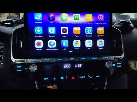
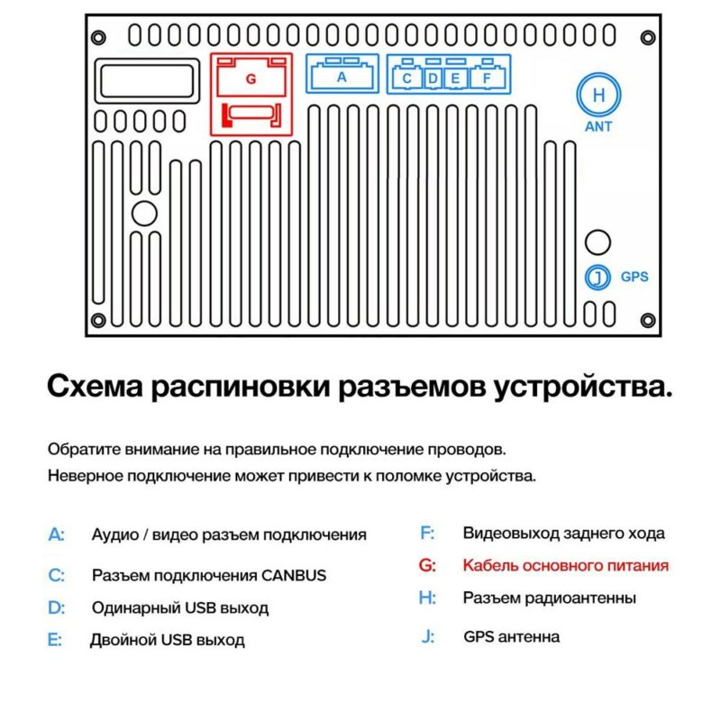
Распиновка автомагнитолы на Андроид 10 (подключение)

Установка русского языка и даты
Для выбора русского языка (например после сброса настроек) войдите в Настройки через главный экран или вытяните панель управления сверху и выберите Настройки. Если активирован английский язык (по умолчанию), то пролистайте меню настроек в самый низ: More Settings -> Language & Input -> Language Settings -> Add a Language -> Нажмите значок лупы в правом углу -> Начните вводить “rus” (появится Русский), выберите его, нажмите Россия. Теперь нужно перетащить строчку с русским языком на первое место. Зажмите эту строчку, она активируется, двигайте вверх, отпускайте. Все, русский язык активирован.
Синхронизация даты по сети
При этом режиме магнитола синхронизирует ваше текущее время автоматически при подключении к Wi-Fi. Для настройки даты можно нажать на часы на главном (домашнем) экране, либо зайти через настройки (если активирован русский язык): Настройки -> Больше настроек -> Дата и Время -> Синхронизация по сети. После чего нужно установить ваш часовой пояс (пункт меню ниже). Отобразится корректное время. Если магнитола подключена корректно, то ей больше не нужно подключаться к сети для синхронизации времени. Она сохранит настройки и благодаря постоянному питанию от аккумулятора будет сохранять текущее время. Время собьется, если магнитола будет полностью обесточена, тогда потребуется подключить ее к wi-fi и время опять станет корректным (дополнительные настройки пояса не потребуются).
Уже приобрели магнитолу? Вам необходим новейший нарульный пульт управления!
Выбирайте из лучших предложений и делайте заказ сегодня по индивидуальной скидке:
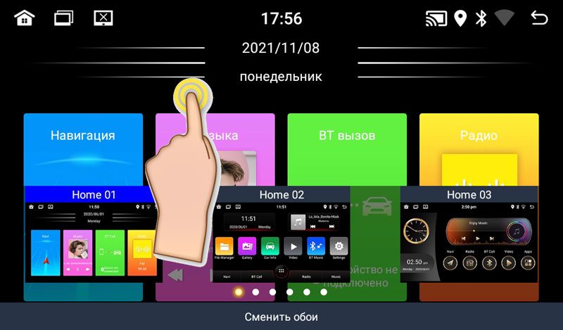
Изменение дизайна интерфейса
Автомагнитолы на системе Андроид 10 (модели А750, А716, А660, А760) обладают встроенной возможностью изменения вида главного экрана и экрана приложений. Для изменения дизайна и выбора одного из 16 вариантов главного экрана нужно:
- Находясь на главном экране произвести длительное касание пустой области экрана. В нижней части появятся иконки с вариантами интерфейса.
- Нажать на вариант нового интерфейса, он сразу активируется.
- Нажмите на пустую область, чтобы варианты исчезли.
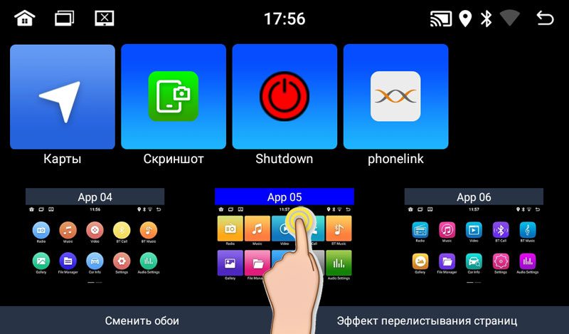
Произведите аналогичные действия, находясь на экране приложений для изменения вида иконок приложений (6 вариантов).
Активация двойного экрана
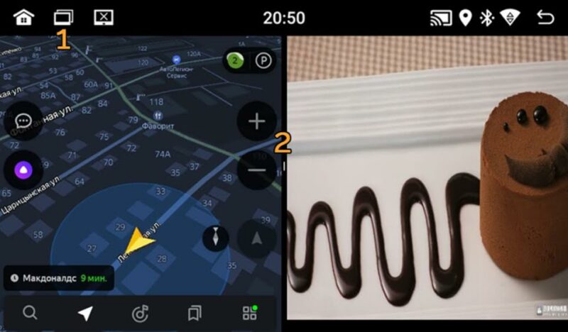
Вы можете использовать одновременно два приложения на одном экране. Для активации функции «Сплит-скрин» зайдите в список запущенных приложений (1), прижмите нужное приложение и перетащите в нужную сторону экрана (на серый фон). Потом кликните на второе приложение, оно откроется на другой половине экрана. Для отмены потяните за ярлычок (2).
Эквалайзер, настройки звука и баланса
Чтобы попасть в раздел настроек звука нужно открыть меню Приложений и нажать иконку “Аудио настройки”. Также в раздел эквалайзера вы можете попасть, находясь в разделе Музыка (соответствующий значок в нижней части экрана). Баланс звука – громкость при активированной камере заднего вида”, громкость Bluetooth настраивается в пункте “Настройки звука” (значок на вытягиваемой сверху панельке) или через “Настройки” -> Аудио (объем).
Скачивание и установка приложений
Для установки приложений из Play Market вам необходимо авторизоваться. Зайдите в Приложения -> Play Маркет – при первом входе начнется “Проверка”. Важно! Убедитесь, что на магнитоле выставлено корректное текущее время и хороший сигнал wi-fi, иначе Проверка – выдаст ошибку.

Обратите внимание, что при первой авторизации процесс “Проверки” может выполнятся достаточно долго – около минуты. Пожалуйста, наберитесь терпения и подождите, пока на экране пропадет вращающийся круг и появится поле для ввода вашей гугл почты (аккаунта).

После авторизации в Play Маркет вы сможете искать и скачивать приложения, аналогично, как и на вашем смартфоне. Пожалуйста, учтите, что магнитола не обладает такой же высокой производительностью, как ваш смартфон и на скачивание и установку приложения может потребоваться больше времени. Пожалуйста, будьте терпиливы. Для удаления приложения прижмите иконку этого приложения на пару секунд, появится окно с подтверждением удаления. Нажмите “Да”.
ВОПРОС: Процесс проверки при первой авторизации в Play Market происходит слишком долго. В чем может быть причина? ОТВЕТ: Такое возможно, если система запустила автоматическое обновление приложений при подключении к Wi-fi. Проверить это можно, вытянув верхнюю панель. В случае обновления под ней отобразится диспетчер загрузки обновления. Нужно подождать или отменить обновление вручную.
Подключение смартфона по MirrorLink (Phonelink)
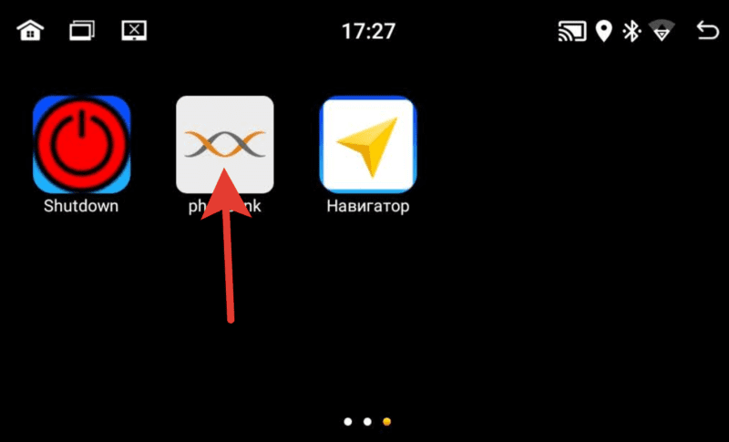
Функция подключения экрана телефона к магнитоле доступна через USB провод и через Wi-fi для смартфонов на Android. И только через Wi-fi для iPhone. Обратите внимание, что сенсорное управление смартфоном через экран магнитолы возможно только при подключении через USB. Для вывода звука, необходимо параллельно подключить ваш смартфон через Bluetooth. При первом подключении потребуется сделать ряд действитй. 1. Откройте приложение phonelink на магнитоле (меню Приложения -> phonelink (на последнем экране).
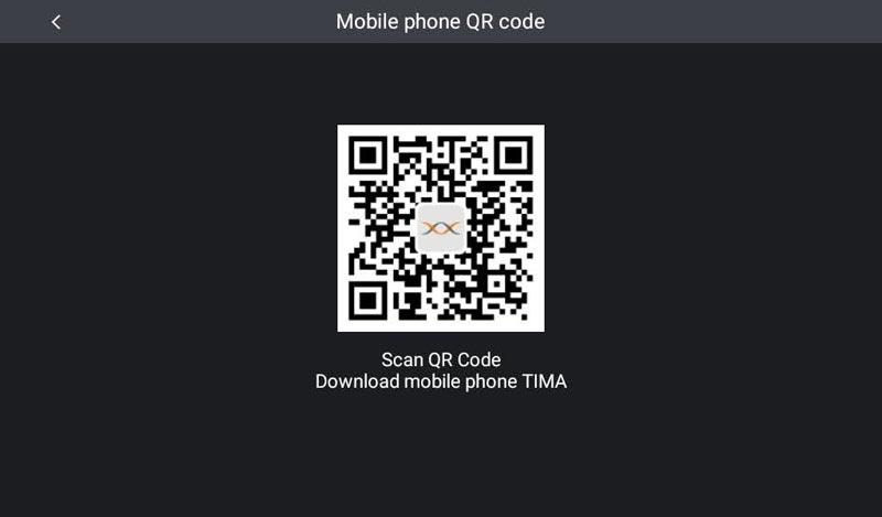
2. Выберите Mobile phone QR code
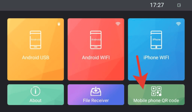
Откроется QR ссылка для скачивания и установки приложения TimaAvn.
3. Подключение Андроид смартфона через USB:
Перед подключением смартфона к магнитоле необходимо в настройках телефона зайти в режим разарботчика и включить опцию Отладка по USB, а также активировать пункт Отладка по USB (настройки безопасности) – это необходимо для управления телефоном через экран магнитолы. Данное действие проводится один раз.
Далее:
- Подключите смартфон к магнитоле через USB провод, начнется зарядка.
- Запустите приложение TimaAvn на смартфоне.
- Откройте phonelink на магнитоле и выберите режим Android USB. Откроется окно, где выполненные пункты будут отмечены желтым ярким маркером:
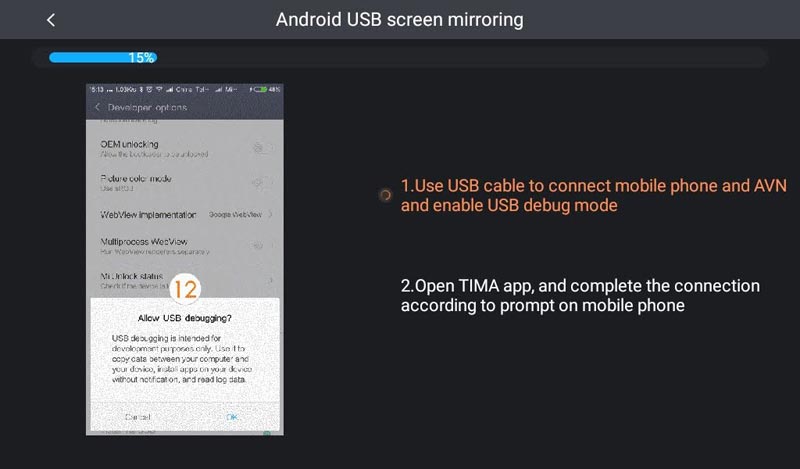
- После того, как на смартфоне появится диалоговое окно, нажмите начать.
Дальнейшее подключение делается буквально в несколько кликов. Просто запустите приложения на смартфоне и на магнитоле, выберите режим и нажмите “Начать” на смартфоне.
Подобрали для вас наилучшие варианты бюджетной автоакустики с крутыми скидками!
Успейте заказать сегодня…
4. Подключение Андроид смартфона через Wi-fi:
- Активируйте точку доступа на вашем смартфоне и подключите к ней магнитолу по wi-fi.
- Запустите приложение TimaAvn на смартфоне.
- Откройте приложение phonelink на магнитоле и выберите пункт Android WIFI. Откроется окно, где выполненные пункты будут отмечены желтым ярким маркером:
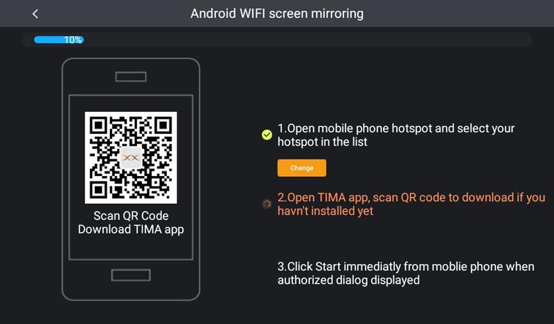
- На экране смартфона появится диалоговое окно. Нажмите “Начать”. Экран смартфона отобразится на экране магнитолы.
Обратите внимание: Управление смартфоном через экран магнитолы при подключении по WIFI недоступно. Также скорость обмена информацией может быть ниже, чем при подключении через USB – изображение может передаваться с небольшой задержкой.
Мультируль. Подключение нарульных контроллеров. Настройка мультируля на магнитоле.
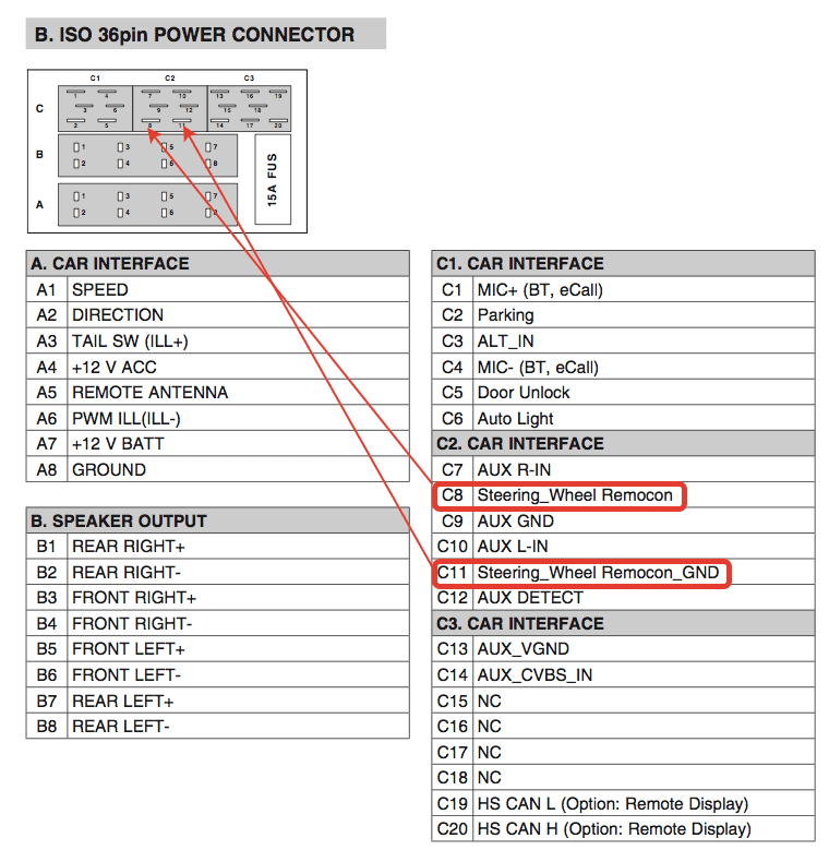
На моделях автомагнитол A750, A760, А716, A660 доступна функция подключения 2-х комплектов штатных кнопок управления на руле автомобиля. Если у вас нет нарульных контроллеров, то вы можете приобрести дополнительно нарульный пульт управления основными функциями магнитолы. Для подключения мультируля нужно корректно определить два провода (или один), отвечающие за передачу сигнала от кнопок руля вашего автомобиля на магнитолу и провод заземления нарульных контроллеров. Сделать это можно с помощью схемы распиновки вашего авто. Чаще всего данные провода на схеме могут обозначаться как:
- Steering_Wheel Remocon – провод питания кнопок и
- Steering_Wheel Remocon_GND – провод заземления кнопок (смотрите пример схемы распиновки Kia Sportage).
После того, как провода определены, вам нужно:
- Подключить провод от автомагнитолы KEY1 к Steering_Wheel Remocon (и KEY2 к аналогичному, если у вас два комплекта нарульных контроллеров).
- Провод заземления Steering_Wheel Remocon_GND на массу автомобиля, либо на черный провод (-) магнитолы.
На этом подключение мультируля завершено, теперь останется только провести обучение кнопок на магнитоле.
Обучение кнопок руля на магнитоле с ОС Андроид 10
Зайдите в меню приложений и выберите “Кнопка рулевого колеса”. Войдите в первый пункт “Кнопка выбора”.

Отметьте функции, к которым хотите привязать рулевые кнопки. Нажмите OK.

Нажмите “Начало”. Выберите функцию и продолжительно нажмите сооветствующую кнопку на руле. Должно появиться сообщение, что кнопка удачно определена. Также сделайте и с остальными функциями. После этого сохраните настройки – последний пункт.
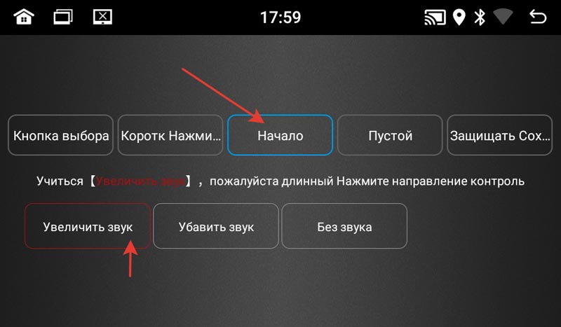
Выйдите в главное меню и проверьте работу всех кнопок. При необходимости повторите процедуру.
Доступ к заводским настройкам
Для доступа к управлению заводскими настройками перейдите в меню Настройки -> Заводская настройка, введите Код: 1234 (и нажать В порядке).
Подсветка сенсорных кнопок боковой панели
На данных моделях автомагнитол возможна активация подсветки сенсорных кнопок управления на боковой панели (только один лунный цвет). Для активации подсветки:
- Зайдите в раздел “Заводская настройка” (см. пункт выше).
- Выберите “Настройки ярких огней”.
- В правой верхней части экрана измените пункт “Руководство по эксплуатации” на “Авто”.
Подсветка активирована.
Настройка кнопок сенсорной панели
Функции кнопок боковой сенсорной панели установлены по умолчанию, но может случиться, что по каким-то причинам данные настройки сбились. Для установки функций сенсорной панели потребуется сделать несколько простых шагов. Войдите в меню заводские настройки:
- Настройки -> Заводская настройка -> Пароль (1234) (нажать “В Пордяке”).
- Далее выберите пункт “Обучение сенсорной кнопке“.
- Нажмите “Начало”. Далее выберите функцию и нажмите соответствующую кнопку на сенсорной панели. После того, как установите все кнопки, нажиите “Конец”.
Как выбрать наилучший усилитель для магнитолы в авто
Выбор усилителя не менее не простая задача, чем выбор автомагнитолы для вашего автомобиля. В этом вопросе нужно быть подкованным технически. Предлагаем вам ознакомиться с главными понятиями усилителей, какие виды автоусилителей звука бывают, какие сегодня бренды наиболее популярны и надежны в этой нише.
И, главное, как выбрать подходящий именно вам усилитель звука в машину. Передя по ссылке вы узнаете, что такое одноканальные, двухканальные и 4-х канальные усилители и в чем отличие данных разновидностей. Также вам представится рейтинг различных многоканальных вариантов усилителей. Читайте о ТОП-20 лучших автомобильных усилителей на 2022 год.