

P7H55
Motherboard

E5291
First Edition V1
January 2010
Copyright © 2010 ASUSTeK Computer Inc. All Rights Reserved.
No part of this manual, including the products and software described in it, may be reproduced,
transmitted, transcribed, stored in a retrieval system, or translated into any language in any form or by any
means, except documentation kept by the purchaser for backup purposes, without the express written
permission of ASUSTeK Computer Inc. (“ASUS”).
Product warranty or service will not be extended if: (1) the product is repaired, modied or altered, unless
such repair, modication of alteration is authorized in writing by ASUS; or (2) the serial number of the
product is defaced or missing.
ASUS PROVIDES THIS MANUAL “AS IS” WITHOUT WARRANTY OF ANY KIND, EITHER EXPRESS
OR IMPLIED, INCLUDING BUT NOT LIMITED TO THE IMPLIED WARRANTIES OR CONDITIONS OF
MERCHANTABILITY OR FITNESS FOR A PARTICULAR PURPOSE. IN NO EVENT SHALL ASUS, ITS
DIRECTORS, OFFICERS, EMPLOYEES OR AGENTS BE LIABLE FOR ANY INDIRECT, SPECIAL,
INCIDENTAL, OR CONSEQUENTIAL DAMAGES (INCLUDING DAMAGES FOR LOSS OF PROFITS,
LOSS OF BUSINESS, LOSS OF USE OR DATA, INTERRUPTION OF BUSINESS AND THE LIKE),
EVEN IF ASUS HAS BEEN ADVISED OF THE POSSIBILITY OF SUCH DAMAGES ARISING FROM ANY
DEFECT OR ERROR IN THIS MANUAL OR PRODUCT.
SPECIFICATIONS AND INFORMATION CONTAINED IN THIS MANUAL ARE FURNISHED FOR
INFORMATIONAL USE ONLY, AND ARE SUBJECT TO CHANGE AT ANY TIME WITHOUT NOTICE,
AND SHOULD NOT BE CONSTRUED AS A COMMITMENT BY ASUS. ASUS ASSUMES NO
RESPONSIBILITY OR LIABILITY FOR ANY ERRORS OR INACCURACIES THAT MAY APPEAR IN THIS
MANUAL, INCLUDING THE PRODUCTS AND SOFTWARE DESCRIBED IN IT.
Products and corporate names appearing in this manual may or may not be registered trademarks or
copyrights of their respective companies, and are used only for identication or explanation and to the
owners’ benet, without intent to infringe.
Offer to Provide Source Code of Certain Software
This product may contain copyrighted software that is licensed under the General Public License (“GPL”)
and under the Lesser General Public License Version (“LGPL”). The GPL and LGPL licensed code in this
product is distributed without any warranty. Copies of these licenses are included in this product.
You may obtain the complete corresponding source code (as dened in the GPL) for the GPL Software,
and/or the complete corresponding source code of the LGPL Software (with the complete machinereadable “work that uses the Library”) for a period of three years after our last shipment of the product
including the GPL Software and/or LGPL Software, which will be no earlier than December 1, 2011, either
(1) for free by downloading it from http://support.asus.com/download;
or
(2) for the cost of reproduction and shipment, which is dependent on the preferred carrier and the location
where you want to have it shipped to, by sending a request to:
ASUSTeK Computer Inc.
Legal Compliance Dept.
15 Li Te Rd.,
Beitou, Taipei 112
Taiwan
In your request please provide the name, model number and version, as stated in the About Box of the
product for which you wish to obtain the corresponding source code and your contact details so that we
can coordinate the terms and cost of shipment with you.
The source code will be distributed WITHOUT ANY WARRANTY and licensed under the same license as
the corresponding binary/object code.
This offer is valid to anyone in receipt of this information.
ASUSTeK is eager to duly provide complete source code as required under various Free Open Source
Software licenses. If however you encounter any problems in obtaining the full corresponding source code
we would be much obliged if you give us a notication to the email address gpl@asus.com, stating the
product and describing the problem (please do NOT send large attachments such as source code archives
etc to this email address).
ii

Contents
Notices …………………………………………………………………………………………… vi
Safety information …………………………………………………………………………. vii
About this guide ……………………………………………………………………………. vii
P7H55 specications summary ……………………………………………………….. ix
Chapter 1: Product introduction
1.1 Welcome! ………………………………………………………………………….. 1-1
1.2 Package contents ………………………………………………………………. 1-1
1.3 Special features …………………………………………………………………. 1-1
1.3.1 Product highlights ………………………………………………….. 1-1
1.3.2 Innovative ASUS features ……………………………………….. 1-2
1.4 Before you proceed …………………………………………………………… 1-5
1.5 Motherboard overview ……………………………………………………….. 1-6
1.5.1 Placement direction ……………………………………………….. 1-6
1.5.2 Screw holes ………………………………………………………….. 1-6
1.5.3 Motherboard layout ………………………………………………… 1-7
1.5.4 Layout contents ……………………………………………………… 1-7
1.6 Central Processing Unit (CPU) …………………………………………… 1-8
1.6.1 Installing the CPU ………………………………………………….. 1-8
1.6.2 Installing the CPU heatsink and fan ………………………….1-11
1.6.3 Uninstalling the CPU heatsink and fan ……………………. 1-12
1.7 System memory ………………………………………………………………. 1-13
1.7.1 Overview …………………………………………………………….. 1-13
1.7.2 Memory congurations ………………………………………….. 1-14
1.7.3 Installing a DIMM …………………………………………………. 1-15
1.7.4 Removing a DIMM ……………………………………………….. 1-15
1.8 Expansion slots ……………………………………………………………….. 1-16
1.8.1 Installing an expansion card ………………………………….. 1-16
1.8.2 Conguring an expansion card ………………………………. 1-16
1.8.3 PCI slots ……………………………………………………………… 1-16
1.8.4 PCI Express x1 slots …………………………………………….. 1-16
1.8.5 PCI Express x16 slot …………………………………………….. 1-16
1.9 Jumpers ………………………………………………………………………….. 1-17
1.10 MemOK! switch ……………………………………………………………….. 1-19
iii

Contents
1.11 Connectors ……………………………………………………………………… 1-20
1.11.1 Rear panel connectors ………………………………………….. 1-20
1.11.2 Internal connectors ………………………………………………. 1-21
1.12 Software support ……………………………………………………………… 1-27
1.12.1 Installing an operating system ……………………………….. 1-27
1.12.2 Support DVD information ………………………………………. 1-27
Chapter 2: BIOS information
2.1 Managing and updating your BIOS …………………………………….. 2-1
2.1.1 ASUS Update utility ……………………………………………….. 2-1
2.1.2 ASUS EZ Flash 2 …………………………………………………… 2-2
2.1.3 ASUS CrashFree BIOS …………………………………………… 2-3
2.1.4 ASUS BIOS Updater ………………………………………………. 2-3
2.2 BIOS setup program ………………………………………………………….. 2-6
2.2.1 BIOS menu screen …………………………………………………. 2-7
2.2.2 Menu bar ………………………………………………………………. 2-7
2.2.3 Navigation keys ……………………………………………………… 2-7
2.2.4 Menu items …………………………………………………………… 2-7
2.2.5 Submenu items ……………………………………………………… 2-8
2.2.6 Conguration elds ………………………………………………… 2-8
2.2.7 Pop-up window ……………………………………………………… 2-8
2.2.8 Scroll bar ………………………………………………………………. 2-8
2.2.9 General help …………………………………………………………. 2-8
2.3 Main menu ………………………………………………………………………… 2-8
2.3.1 System Time ………………………………………………………… 2-9
2.3.2 System Date …………………………………………………………. 2-9
2.3.3 SATA1~6 ………………………………………………………………. 2-9
2.3.5 System Information ………………………………………………. 2-10
2.3.4 Storage Conguration …………………………………………… 2-10
2.4 Ai Tweaker menu ……………………………………………………………… 2-11
2.4.1 Ai Overclock Tuner ………………………………………………..2-11
2.4.2 CPU Ratio Setting ……………………………………………….. 2-12
2.4.3 Intel(R) SpeedStep(TM) Tech ……………………………….. 2-12
2.4.4 Intel(R) TurboMode Tech ………………………………………. 2-12
2.4.5 Xtreme Phase Full Power Mode ……………………………. 2-12
iv

Contents
2.4.6 DRAM Timing Control ………………………………………….. 2-13
2.5 Advanced menu ………………………………………………………………. 2-17
2.5.1 CPU Conguration ……………………………………………….. 2-17
2.5.2 Uncore Conguration ……………………………………………. 2-19
2.5.3 Onboard Devices Conguration ……………………………… 2-19
2.5.4 USB Conguration ……………………………………………….. 2-19
2.5.5 PCIPnP ………………………………………………………………. 2-20
2.5.6 Intel VT-d ……………………………………………………………. 2-20
2.6 Power menu …………………………………………………………………….. 2-20
2.6.1 Suspend Mode ……………………………………………………. 2-21
2.6.2 ACPI 2.0 Support ………………………………………………… 2-21
2.6.3 ACPI APIC Support ……………………………………………… 2-21
2.6.4 APM Conguration ……………………………………………….. 2-21
2.6.5 Hardware Monitor ………………………………………………… 2-22
2.7 Boot menu ………………………………………………………………………. 2-23
2.7.1 Boot Device Priority ……………………………………………… 2-23
2.7.2 Boot Settings Conguration …………………………………… 2-24
2.7.3 Security ………………………………………………………………. 2-24
2.8 Tools menu ……………………………………………………………………… 2-25
2.8.1 ASUS O.C. Prole ………………………………………………… 2-26
2.8.2 AI NET 2……………………………………………………………… 2-26
2.8.3 ASUS EZ Flash 2 …………………………………………………. 2-26
2.8.4 Express Gate ……………………………………………………… 2-26
2.9 Exit menu ………………………………………………………………………… 2-27
v
Notices
Federal Communications Commission Statement
This device complies with Part 15 of the FCC Rules. Operation is subject to the following two
conditions:
• This device may not cause harmful interference, and
• This device must accept any interference received including interference that may cause
undesired operation.
This equipment has been tested and found to comply with the limits for a Class B digital
device, pursuant to Part 15 of the FCC Rules. These limits are designed to provide
reasonable protection against harmful interference in a residential installation. This
equipment generates, uses and can radiate radio frequency energy and, if not installed
and used in accordance with manufacturer’s instructions, may cause harmful interference
to radio communications. However, there is no guarantee that interference will not occur
in a particular installation. If this equipment does cause harmful interference to radio or
television reception, which can be determined by turning the equipment off and on, the user
is encouraged to try to correct the interference by one or more of the following measures:
•
Reorient or relocate the receiving antenna.
•
Increase the separation between the equipment and receiver.
•
Connect the equipment to an outlet on a circuit different from that to which the receiver is
connected.
•
Consult the dealer or an experienced radio/TV technician for help.
The use of shielded cables for connection of the monitor to the graphics card is required
to assure compliance with FCC regulations. Changes or modications to this unit not
expressly approved by the party responsible for compliance could void the user’s authority
to operate this equipment.
Canadian Department of Communications Statement
This digital apparatus does not exceed the Class B limits for radio noise emissions from
digital apparatus set out in the Radio Interference Regulations of the Canadian Department
of Communications.
This class B digital apparatus complies with Canadian ICES-003.
REACH
Complying with the REACH (Registration, Evaluation, Authorisation, and Restriction of
Chemicals) regulatory framework, we published the chemical substances in our products at
ASUS REACH website at http://green.asus.com/english/REACH.htm.
DO NOT throw the motherboard in municipal waste. This product has been designed to
enable proper reuse of parts and recycling. This symbol of the crossed out wheeled bin
indicates that the product (electrical and electronic equipment) should not be placed in
municipal waste. Check local regulations for disposal of electronic products.
DO NOT throw the mercury-containing button cell battery in municipal waste. This symbol
of the crossed out wheeled bin indicates that the battery should not be placed in municipal
waste.
vi

Safety information
Electrical safety
• To prevent electric shock hazard, disconnect the power cable from the electric outlet
before relocating the system.
• When adding or removing devices to or from the system, ensure that the power cables
for the devices are unplugged before the signal cables are connected. If possible,
disconnect all power cables from the existing system before you add a device.
• Before connecting or removing signal cables from the motherboard, ensure that all
power cables are unplugged.
• Seek professional assistance before using an adapter or extension cord. These devices
could interrupt the grounding circuit.
• Ensure that your power supply is set to the correct voltage in your area. If you are not
sure about the voltage of the electrical outlet you are using, contact your local power
company.
• If the power supply is broken, do not try to x it by yourself. Contact a qualied service
technician or your retailer.
Operation safety
•
Before installing the motherboard and adding devices on it, carefully read all the manuals
that came with the package.
•
Before using the product, ensure that all cables are correctly connected and the power
cables are not damaged. If you detect any damage, contact your dealer immediately.
•
To avoid short circuits, keep paper clips, screws, and staples away from connectors,
slots, sockets and circuitry.
•
Avoid dust, humidity, and temperature extremes. Do not place the product in any area
where it may become wet.
•
Place the product on a stable surface.
•
If you encounter technical problems with the product, contact a qualied service
technician or your retailer.
About this guide
This user guide contains the information you need when installing and conguring the
motherboard.
How this guide is organized
This guide contains the following parts:
• Chapter 1: Product introduction
This chapter describes the features of the motherboard and the new technology it
supports.
• Chapter 2: BIOS information
This chapter tells how to change system settings through the BIOS Setup menus.
Detailed descriptions of the BIOS parameters are also provided.
vii

Conventions used in this guide
To ensure that you perform certain tasks properly, take note of the following symbols used
throughout this manual.
DANGER/WARNING: Information to prevent injury to yourself when trying to
complete a task.
CAUTION: Information to prevent damage to the components when trying to
complete a task.
IMPORTANT: Instructions that you MUST follow to complete a task.
NOTE: Tips and additional information to help you complete a task.
Where to nd more information
Refer to the following sources for additional information and for product and software
updates.
1. ASUS websites
The ASUS website provides updated information on ASUS hardware and software
products. Refer to the ASUS contact information.
2. Optional documentation
Your product package may include optional documentation, such as warranty yers,
that may have been added by your dealer. These documents are not part of the
standard package.
Typography
Bold text Indicates a menu or an item to select.
Italics
Used to emphasize a word or a phrase.
<Key> Keys enclosed in the less-than and greater-than sign means
that you must press the enclosed key.
Example: <Enter> means that you must press the Enter or
Return key.
<Key1>+<Key2>+<Key3> If you must press two or more keys simultaneously, the key
names are linked with a plus sign (+).
Example: <Ctrl>+<Alt>+<D>
viii

P7H55 specications summary
CPU LGA1156 socket for Intel® Core™ i7/ Core™ i5/ Core™ i3
Chipset Intel® H55 Express Chipset
Memory Dual-channel memory architecture
Expansion slots 1 x PCI Express™ 2.0 x16 slot
Storage Intel® H55 Express Chipset:
LAN Realtek® RTL8112L Gigabit LAN controller featuring AI NET2
Audio VIA 1708S 8-channel High Denition Audio CODEC
USB Supports up to 12 USB 2.0/1.1 ports (4 ports at mid-board,
/ Pentium® processors
Supports Intel® Turbo Boost Technology
* The Intel® Turbo Boost Technology support depends on CPU
types
** Refer to www.asus.com for Intel® CPU support list.
4 x 240-pin DIMM slots support maximum 16GB unbuffered
non-ECC DDR3 2200(O.C.)/2000 /1866 /1600 /1333 /MHz
memory modules
* Supports Intel® Extreme Memory Prole (XMP)
** Hyper DIMM support is subject to the physical
characteristics of individual CPUs. Some hyper DIMMs only
support one DIMM per channel.
*** Refer to www.asus.com for the latest Memory QVL
(Qualied Vendors List).
**** When you install a total memory of 4GB or more,
Windows® 32-bit operating system may only recognize less
than 3GB. We recommend a maximum of 3GB system
memory if you are using a Windows® 32-bit operating
system.
3 x PCI Express™ 2.0 x1 slots (2.5GT/s, gray slots)
3 x PCI slots
— 6 x SATA 3.0 Gb/s connectors
VIA® VT6415 PATA controller:
— 1 x Ultra DMA 133/100 connector for up to 2 PATA
devices
— Optical S/PDIF out port at back I/O
— Supports Jack-detection and Multi-streaming
8 ports at the back panel)
(continued on the next page)
ix

P7H55 specications summary
ASUS unique features ASUS Exclusive Overclocking Features:
ASUS exclusive
overclocking features
Back panel I/O ports 1 x PS/2 keyboard port
— ASUS TurboV
— ASUS Turbo Key
ASUS Exclusive Features:
— MemOK!
— ASUS EPU
— Express Gate
ASUS Quiet Thermal Solution:
— ASUS Fanless Design: Stylish Heatsink Solution,
MOS Heatsink
— ASUS Fan Xpert
ASUS EZ DIY:
— ASUS O.C. Prole
— ASUS CrashFree BIOS 3
— ASUS EZ Flash 2
— ASUS My Logo 2
— Multi-language BIOS
Precision Tweaker 2:
— vCore: Adjustable CPU voltage at 0.00625V increment
— vIMC: Adjustable IMC voltage at 0.05V increment
— vDRAM Bus: 11-step DRAM voltage control
— vPCH: 2-step chipset voltage control
— vCPU PLL: 4-step reference voltage control
SFS (Stepless Frequency Selection):
— Internal Base Clock tuning from 80 MHz up to 500 MHz
at 1MHz increment
— PCI Express frequency tuning from 100MHz up to
200MHz at 1MHz increment
Overclocking Protection:
— ASUS C.P.R.(CPU Parameter Recall)
1 x PS/2 mouse port
1 x Optical S/PDIF Out port
1 x LAN (RJ-45) port
8 x USB 2.0/1.1 ports
8-channel audio I/O ports
(continued on the next page)
x

P7H55 specications summary
Internal I/O
connectors
BIOS 16 Mb Flash ROM, AMI BIOS, PnP, DMI 2.0, WfM 2.0,
Manageability WfM 2.0, DMI 2.0, WOL by PME, WOR by PME, PXE
Accessories 1 x Ultra DMA 133/100 cable
Support DVD Drivers
Form factor ATX form factor: 12 in x 8.6 in (30.5 cm x 21.8 cm)
2 x USB 2.0/1.1 connectors support additional 4 USB 2.0/1.1
ports
1 x IDE connector
6 x SATA connectors
1 x CPU fan connector (1 x 4-pin)
1 x Chassis fan connector (1 x 3-pin)
1 x Power fan connector (1 x 3-pin)
1 x Front panel audio connector
1 x S/PDIF Out header
1 x CD audio in connector
1 x 24-pin EATX power connector
1 x 4-pin ATX 12V power connector
1 x System panel connector
1 x MemOK! button
1 x COM connector
SM BIOS 2.5, ACPI 2.0a, Multi-language BIOS,
ASUS EZ Flash 2, ASUS CrashFree BIOS 3
2 x Serial ATA 3.0Gb/s cables
1 x I/O shield
1 x User Manual
ASUS Utilities
ASUS Update
Anti-virus software (OEM version)
* Specications are subject to change without notice.
xi
Chapter 1
Product introduction
1.1 Welcome!
Thank you for buying an ASUS® P7H55 motherboard!
The motherboard delivers a host of new features and latest technologies, making it another
standout in the long line of ASUS quality motherboards!
Before you start installing the motherboard, and hardware devices on it, check the items in
your package with the list below.
1.2 Package contents
Check your motherboard package for the following items.
Motherboard ASUS P7H55 motherboard
Cables 2 x Serial ATA 3.0Gb/s cables
1 x Ultra DMA 133/100/66 cable
Accessories 1 x I/O shield
Application DVD ASUS motherboard support DVD
Documentation User Manual
If any of the above items is damaged or missing, contact your retailer.
1.3 Special features
1.3.1 Product highlights
1-1 Chapter 1: Product introduction
Intel® LGA1156 Lynneld/Clarkdale Processor Ready
This motherboard supports the latest Intel® Lynneld and Clarkdale
processors in LGA1156 package, which has memory and PCI Express
controller integrated to support 2-channel (4 DIMMs) DDR3 memory and
16 PCI Express 2.0 lanes, providing great graphics performance. Intel
Lynneld processor is one of the most powerful and energy efcient
CPU in the world. Moreover, Intel® and Clarkdale processor integrated
Graphics Procession Unit (GPU) which goes with Intel® H55 chipset with
VGA out can bring you to he whole new experience of the next generation
VGA performance. It also provides separated 3D, 2D, and Video Engines
to execute different graphic control in hardware.
®
Intel® H55
The Intel® H55 Express Chipset is the latest one-chipset design to
support the latest 1156 socket Intel® Core™ i7 / Core™ i5/ Core™ i3/
Pentium® processors. Intel® H55 provides improved performance by
utilizing serial point-to-point links, allowing increased bandwidth and
stability. Use Intel® Core™ i5 6 Series, Core™ i3 5 Series, and Pentium®
CPU with H55 Express Chipset to enjoy the latest Intel® integrated
graphic performance.
Dual-Channel DDR3 2200(O.C.) / 2000 / 1866 / 1600 / 1333 /
1066 MHz support
The motherboard supports DDR3 memory that features data transfer
rates of 2200(O.C.) / 2000 / 1866 / 1600 / 1333 / 1066 MHz to meet the
higher bandwidth requirements of the latest 3D graphics, multimedia, and
Internet applications. The dual-channel DDR3 architecture enlarges the
bandwidth of your system memory to boost system performance.
S/PDIF digital sound ready
This motherboard provides convenient connectivity to external home
theater audio systems via the S/PDIF-out (SONY-PHILIPS Digital
Interface) jack. It allows digital audio transfer and keeps the best signal
quality.
8-channel audio CODEC
Enjoy high-end sound quality on your PC! The onboard 8-channel High
Denition Audio CODEC enables high-quality 192KHz/24-bit audio
output, jack-sensing feature, and multi-streaming technology.
Gigabit LAN solution
The onboard LAN controller is a highly integrated Gb LAN controller. It is
enhanced with an ACPI management function to provide efcient power
management for advanced operating systems.
1.3.2 Innovative ASUS features
Turbo Key
ASUS Turbo Key allows you to turn the PC power button into a physical
overclocking button. After the easy setup, Turbo Key can boost
performances without interrupting ongoing work or games—with just one
touch!
ASUS TurboV
Feel the adrenaline rush of real-time OC-now a reality with the ASUS
TurboV. This easy OC tool allows you to overclock without exiting or
rebooting the OS; and its user-friendly interface makes overclock with just
a few clicks away. Moreover, the ASUS OC proles in TurboV provides
the best O.C. settings in different scenarios.
ASUS P7H55 1-2
MemOK!
MemOK! quickly ensures memory boot compatibility. This remarkable
memory rescue tool requires a mere push or a button to patch memory
issues. MemOK! determines failsafe settings and dramatically improves
your system boot success. Get your system up and running in no time!
ASUS EPU
ASUS EPU is a unique power saving technology that detects the current
system loadings and adjusts the power consumption in real time.
ASUS Express Gate
Express Gate is an ASUS exclusive OS, which lets you instantly access
the Internet and key applications before entering the Windows® OS.
• ASUS Express Gate supports installation on SATA HDDs, USB HDDs and ash
drives with at least 1.2GB free disk space. When installing it on USB HDDs or
ash drives, connect the drives to the motherboard USB port before turning on the
computer.
• The actual boot time depends on the system conguration.
• ASUS Express Gate supports le uploading from SATA HDDs, ODDs and USB
drives. It supports le downloading to USB drives only.
Stylish Heatsink
The crystal-shaped heatsink features 0-dB thermal solution that offers
users a noiseless PC environment. Not only the beautiful shape upgrades
the visual enjoyment for motherboard users, but also the heatsink design
lowers the temperature of the chipset and power phase area through
high efcient heat-exchange. Combined with usability and aesthetics, the
ASUS crystal-shaped heatsink will give users an extremely silent and
cooling experience with the elegant appearance!
ASUS Fan Xpert
ASUS Fan Xpert intelligently allows you to adjust both the CPU and
chassis fan speeds according to different ambient temperatures caused
by different climate conditions in different geographic regions and your
PC’s loading. The built-in variety of useful proles offer exible controls of
fan speed to achieve a quiet and cool environment.
ASUS O.C. Prole
The motherboard features the ASUS O.C. Prole that allows you to
conveniently store or load multiple BIOS settings. The BIOS settings can
be stored in the CMOS or a separate le, giving you the freedom to share
and distribute your favorite settings.
1-3 Chapter 1: Product introduction

ASUS MyLogo2™
This feature allows you to convert your favorite photo into a 256-color
boot logo for a more colorful and vivid image on your screen.
ASUS CrashFree BIOS 3
ASUS CrashFree BIOS 3 is an auto-recovery tool that allows you to
restore a corrupted BIOS le using the bundled support DVD or USB
ash disk that contains the latest BIOS le.
ASUS EZ Flash 2
ASUS EZ Flash 2 is a utility that allows you to update the BIOS without
using an OS-based utility.
ASUS AI NET2
ASUS AI NET2 remotely detects the cable connection immediately after
turning on the system, and any faulty cable connections are reported
back up to 100 meters at 1 meter accuracy.
C.P.R. (CPU Parameter Recall)
The BIOS C.P.R. feature automatically restores the CPU default settings
when the system hangs due to overclocking failure. C.P.R. eliminates the
need to open the system chassis and clear the RTC data. Simply shut
down and reboot the system, and the BIOS automatically restores the
CPU parameters to their default settings.
Green ASUS
This motherboard and its packaging comply with the European Union’s
Restriction on the use of Hazardous Substances (RoHS). This is in line
with the ASUS vision of creating environment-friendly and recyclable
products/packaging to safeguard consumers’ health while minimizing the
impact on the environment.
ASUS P7H55 1-4
1.4 Before you proceed
P7H55
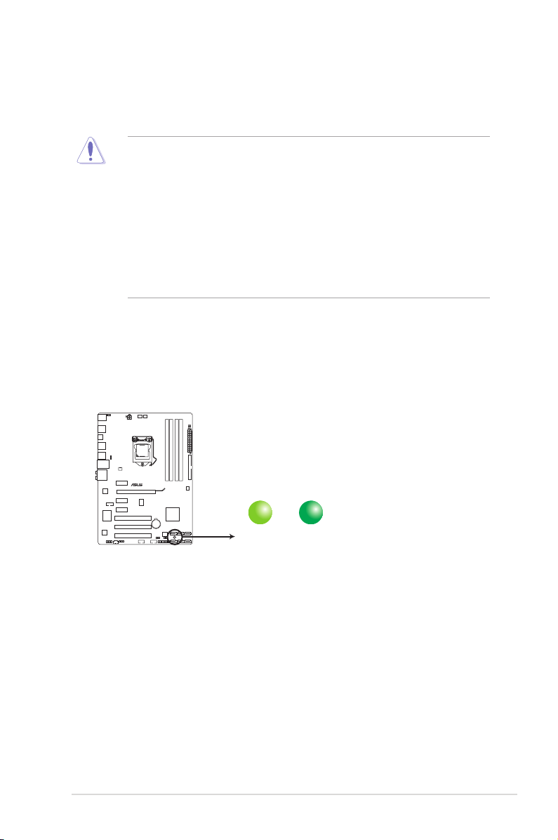
SB_PWR
ON
Standby Power Powered Off
OFF
P7H55 Onboard LED
Take note of the following precautions before you install motherboard components or change
any motherboard settings.
• Unplug the power cord from the wall socket before touching any component.
• Before handling components, use a grounded wrist strap or touch a safely grounded
object or a metal object, such as the power supply case, to avoid damaging them due to
static electricity.
• Hold components by the edges to avoid touching the ICs on them.
• Whenever you uninstall any component, place it on a grounded antistatic pad or in the
bag that came with the component.
• Before you install or remove any component, ensure that the ATX power supply is
switched off or the power cord is detached from the power supply. Failure to do so may
cause severe damage to the motherboard, peripherals, or components.
Onboard LED
The motherboard comes with a standby power LED that lights up to indicate that the system
is ON, in sleep mode, or in soft-off mode. This is a reminder that you must shut down
the system and unplug the power cable before removing or plugging in any motherboard
component. The illustration below shows the location of the onboard LED.
1-5 Chapter 1: Product introduction
1.5 Motherboard overview
Before you install the motherboard, study the conguration of your chassis to ensure that the
motherboard ts into it.
Ensure that you unplug the power cord before installing or removing the motherboard.
Failure to do so can cause you physical injury and damage motherboard components.
1.5.1 Placement direction
When installing the motherboard, ensure that you place it into the chassis in the correct
orientation. The edge with external ports goes to the rear part of the chassis as indicated in
the image below.
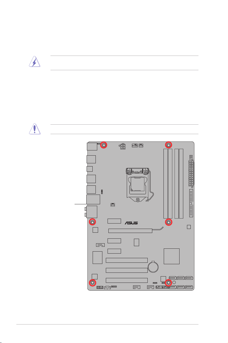
1.5.2 Screw holes
Place six screws into the holes indicated by circles to secure the motherboard to the chassis.
Do not overtighten the screws! Doing so can damage the motherboard.
Place this side towards
the rear of the chassis
ASUS P7H55 1-6
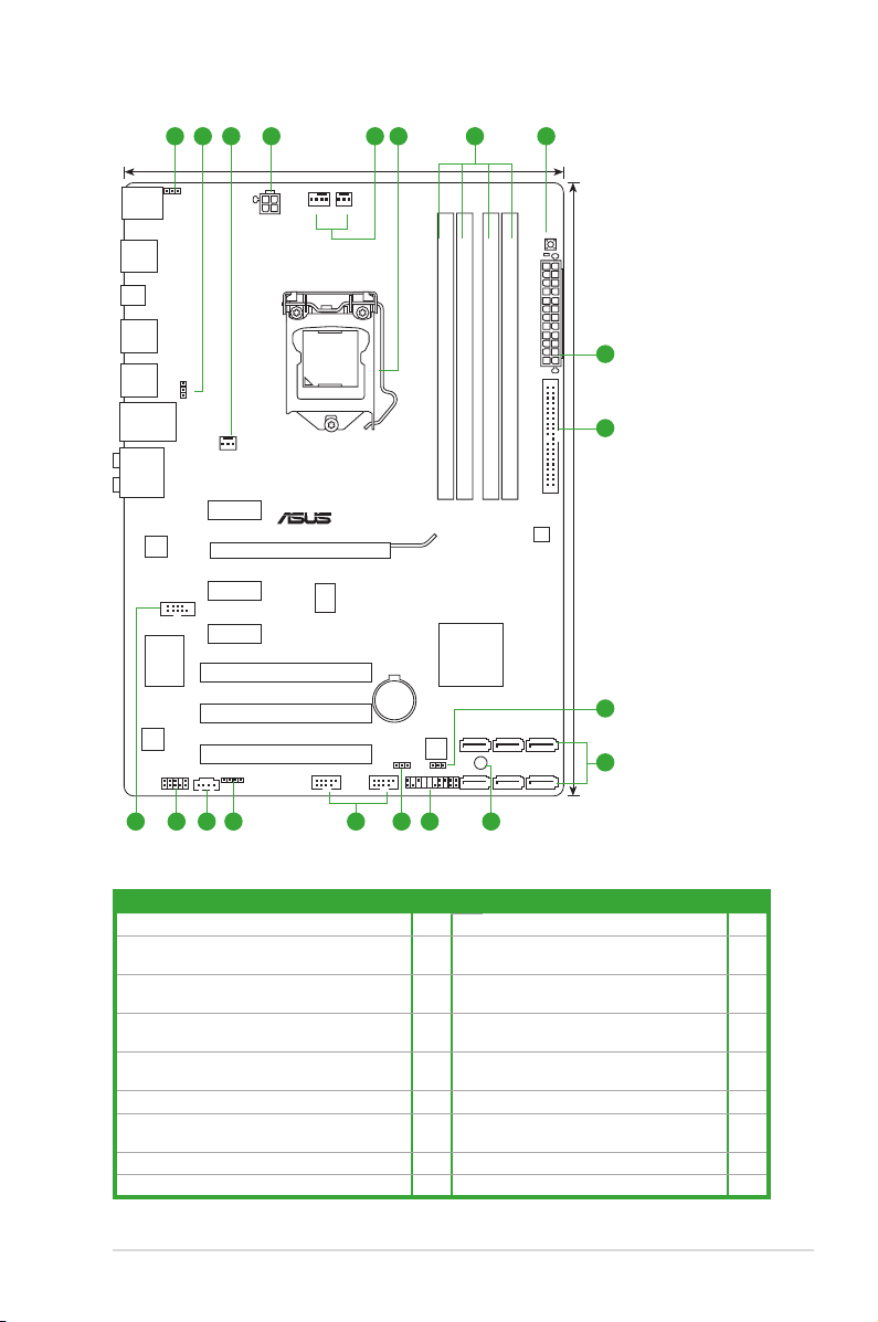
1.5.3 Motherboard layout
P7H55
PCIEX16
PCIEX1_2
PCIEX1_1
PCIEX1_3
PCI1
PCI2
PCI3
PRI_IDE
MemOK!
DRAM_LED
USB1112 USB910
PANEL
SPDIF_OUT
CD
AAFP
ATX12V
EATXPWR
CPU_FAN
PWR_FAN
CHA_FAN
Lithium Cell
CMOS Power
Super
I/O
AUDIO
VIA
VT1708S
Realtek
8112L
COM1
KBMS
8Mb
BIOS
SB_PWR
CLRTC
USBPW9-12
21.8cm(8.6in)
30.5cm(12.0in)
Intel
®
H55
DDR3 DIMM_A2 (64bit, 240-pin module)
DDR3 DIMM_A1 (64bit, 240-pin module)
DDR3 DIMM_B2 (64bit, 240-pin module)
DDR3 DIMM_B1 (64bit, 240-pin module)
LAN_USB12
USB34
USB56
USB78
SPDIF_O2
SATA4 SATA5 SATA6
SATA1 SATA2 SATA3
LGA1156
VIA
VT6415
ICS
9LRS954
KBPWR
USBPW1-8
4
4
1 2 3 6 73 5
8
10
9
12 111416 1517 13 2
1.5.4 Layout contents
Connectors/Jumpers/Slots/LED Page Connectors/Jumpers/Slots/LED Page
1. Keyboard power (3-pin KBPWR) 1-18 10. Serial ATA connectors (7-pin SATA1-6) 1-25
2. USB device wake-up (3-pin USBPW1-8, 3-pin
USBPW9-12)
3. CPU, power, and chassis fan connectors (4-pin
CPU_FAN, 3-pin PWR_FAN, 3-pin CHA_FAN)
4. ATX power connectors (24-pin EATXPWR, 4-pin
ATX12V)
5. LGA1156 CPU socket 1-8 14. Digital audio connector (4-1 pin
6. DDR3 DIMM slots 1-13 15. Optical drive audio connector (4-pin CD) 1-22
7. MemOK! Switch 1-19 16. Front panel audio connector (10-1 pin
8. IDE connector (40-1 pin PRI_EIDE) 1-22 17. Serial port connector (10-1 pin COM1) 1-25
9. Clear RTC RAM (3-pin CLRTC) 1-17
1-7 Chapter 1: Product introduction
1-18 11. Onboard LED (SB_PWR) 1-5
1-24 12. System panel connector (20-8 pin PANEL) 1-26
1-23 13. USB connectors (10-1 pin USB910,
USB1112)
SPDIF_OUT)
AAFP)
1-23
1-24
1-21
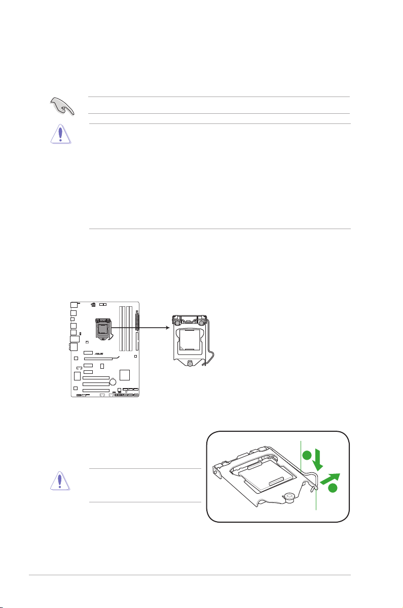
1.6 Central Processing Unit (CPU)
P7H55
P7H55 CPU socket LGA1156
The motherboard comes with a surface mount LGA1156 socket designed for the Intel®
Core™ i7 / Core™ i5 / Core™ i3 / Pentium® processors.
Unplug all power cables before installing the CPU.
• Upon purchase of the motherboard, ensure that the PnP cap is on the socket and the
socket contacts are not bent. Contact your retailer immediately if the PnP cap is missing,
or if you see any damage to the PnP cap/socket contacts/motherboard components.
ASUS will shoulder the cost of repair only if the damage is shipment/transit-related.
• Keep the cap after installing the motherboard. ASUS will process Return Merchandise
Authorization (RMA) requests only if the motherboard comes with the cap on the
LGA1156 socket.
• The product warranty does not cover damage to the socket contacts resulting from
incorrect CPU installation/removal, or misplacement/loss/incorrect removal of the PnP
cap.
1.6.1 Installing the CPU
To install a CPU:
1. Locate the CPU socket on the motherboard.
2. Press the load lever with your thumb (A),
and then move it to the right (B) until it is
Load lever
released from the retention tab.
To prevent damage to the socket pins,
do not remove the PnP cap unless
you are installing a CPU.
ASUS P7H55 1-8
Retention tab
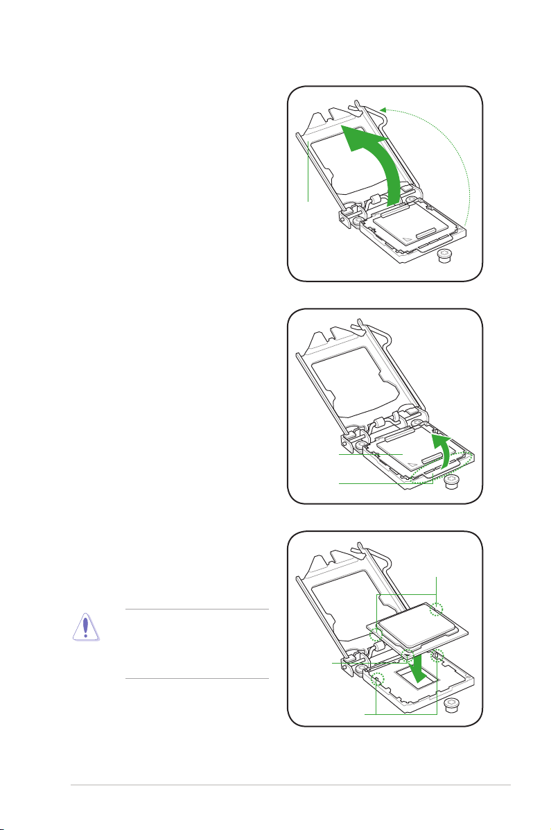
3. Lift the load lever in the direction of the
arrow until the load plate is completely
lifted.
4. Remove the PnP cap from the CPU
socket by lifting the tab only.
Load plate
PnP cap
Cap tab
5. Position the CPU over the socket,
ensuring that the gold triangle is on the
bottom-left corner of the socket, and
then t the socket alignment keys into
CPU notches
the CPU notches.
The CPU ts in only one correct
orientation. DO NOT force the CPU
into the socket to prevent bending
the connectors on the socket and
damaging the CPU!
1-9 Chapter 1: Product introduction
Gold
triangle
mark
Alignment keys
Loading…
Инструкция и руководство для
Asus P7H55-M LX
22 страницы подробных инструкций и пользовательских руководств по эксплуатации на русском на испанском на французском на итальянском на чешском на немецком на польском
12:45
Помощь по выбору материнских плат на сокет 1156. Для работы и игр. Детальный гайд
09:34
Обзор материнской платы Asus P7 H55. Тесты связки X3440 4ГГЦ и RX 470
18:46
Руководство по разгону на сокете 1156 (MB — ASUS), Xeon X3400 серии, разгон ОЗУ и NB
07:21
Как встрять на 5300р или материнка с aliexpress !!
06:46
РАЗГОН X3440 НА Asus P7H55-M LX
10:09
Разгон XEON X3440 1156 + GTX 1060
04:16
ทดสอบเมนบอร์ด P7H55-M LX 1156
06:11
Обзор материнской платы ASUS P8B75-M LX PLUS unboxing
Нажмите на кнопку для помощи
— У вас стиральная машина Indesit?
— Нет не индезит, раньше индезела, а сейчас — нет.
— А стиральный порошок Persil?
— А он должен был персить?
-
Драйверы
21
-
Инструкции по эксплуатации
3
Языки:
ASUS P7H55 инструкция по эксплуатации
(66 страниц)
- Языки:Английский
-
Тип:
PDF -
Размер:
3.88 MB -
Описание:
P7H55 user’s manual (English)
Просмотр
ASUS P7H55 инструкция по эксплуатации
(1 страница)
- Языки:Английский
-
Тип:
PDF -
Размер:
407.58 KB
Просмотр
ASUS P7H55 инструкция по эксплуатации
(71 страница)
- Языки:Французский
-
Тип:
PDF -
Размер:
4.04 MB -
Описание:
P7H55 user’s manual (French)
Просмотр
На NoDevice можно скачать инструкцию по эксплуатации для ASUS P7H55. Руководство пользователя необходимо для ознакомления с правилами установки и эксплуатации ASUS P7H55. Инструкции по использованию помогут правильно настроить ASUS P7H55, исправить ошибки и выявить неполадки.
-
Page 1: Asus P7H55
Motherboard P7H55/USB3[…]
-
Page 2: Asus P7H55
ii E5833 First Edition (V1) May 2010 Copyright © 2010 ASUST eK COMPUTER INC. All Rights Reserved. No part of this manual, including the products and software described in it, may be reproduced, transmitted, transcribed, stored in a retrieval system, or translated into any language in any form or by any means, except documentation kept by the purch[…]
-
Page 3: Asus P7H55
iii Contents Notices …………………………………………………………………………………………… vi Safety information …………………………………………………………………………. vii About this guide …………………………………………………………………………… viii P[…]
-
Page 4: Asus P7H55
iv Contents 2.1.1 ASUS Update ………………………………………………………… 2-1 2.1.2 ASUS EZ Flash 2 …………………………………………………… 2-2 2.1.3 ASUS CrashFree BIOS 3 utility ……………………………….. 2-3 2.2 BIOS setup program ……………………………………………………[…]
-
Page 5: Asus P7H55
v Contents 2.5.2 Uncore Conguration ……………………………………………. 2-17 2.5.3 Onboard Device Conguration ……………………………….. 2-17 2.5.4 USB Conguration ……………………………………………….. 2-17 2.5.5 PCIPnP ……………………………………………………………….[…]
-
Page 6: Asus P7H55
vi Notices Federal Communications Commission Statement This device complies with Part 15 of the FCC Rules. Operation is subject to the following two conditions: • This device may not cause harmful interference, and • This device must accept any interference received including interference that may cause undesired operation. This equipment has b[…]
-
Page 7: Asus P7H55
vii Safety information Electrical safety • T o prevent electrical shock hazard, disconnect the power cable from the electrical outlet before relocating the system. • When adding or removing devices to or from the system, ensure that the power cables for the devices are unplugged before the signal cables are connected. If possible, disconnect al[…]
-
Page 8: Asus P7H55
viii About this guide This user guide contains the information you need when installing and conguring the motherboard. How this guide is organized This guide contains the following parts: • Chapter 1: Product introduction This chapter describes the features of the motherboard and the new technology it supports. • Chapter 2: BIOS information […]
-
Page 9: Asus P7H55
ix P7H55/USB3 specications summary (continued on the next page) CPU LGA1 156 socket for Intel ® Core™ i7 / Core™ i5 / Core™ i3 / Pentium™ Processors Supports Intel ® T urbo Boost T echnology * The Intel ® Turbo Boost T echnology support depends on the CPU types. ** Refer to www .asus.com for Intel CPU support list Chipset Intel ® H55[…]
-
Page 10: Asus P7H55
x P7H55/USB3 specications summary ASUS Unique Features Hybrid Processer: — ASUS T urboV EVO, T urboV , Auto Tuning Hybrid Switch: — T urbo Key II Hybrid OS: — Express Gate ASUS Exclusive Features: — MemOK! — ASUS EPU ASUS Quiet Thermal Solution: — ASUS Fanless Design: Stylish Heatsink Solution, MOS Heatsink — ASUS Fan Xpert ASUS EZ DIY : — ASUS […]
-
Page 11: Asus P7H55
xi P7H55/USB3 specications summary Internal I/O Connectors 2 x USB connectors support additional 4 USB ports 6 x SA T A 3Gb/s connectors 1 x 4-pin CPU Fan connector 1 x 3-pin Chassis Fan connector 1 x 3-pin Power Fan connector 1 x Front panel audio connector 1 x S/PDIF Out header 1 x CD audio in 1 x 24-pin EA TX Power connector 1 x 4-pin A TX 12[…]
-
Page 12: Asus P7H55
xii[…]
-
Page 13: Asus P7H55
ASUS P7H55/USB3 1-1 If any of the items is damaged or missing, contact your retailer . 1.1 Before you proceed T ake note of the following precautions before you install motherboard components or change any motherboard settings. • Unplug the power cord from the wall socket before touching any component. • Before handling components, use a ground[…]
-
Page 14: Asus P7H55
1-2 Chapter 1: Product introduction 1.2.2 Layout contents 1.2 Motherboard overview 1.2.1 Motherboard layout Place six screws into the holes indicated by circles to secure the motherboard to the chassis. DO NOT overtighten the screws! Doing so can damage the motherboard. Place this side towards the rear of the chassis. Ensure that you install the mo[…]
-
Page 15: Asus P7H55
ASUS P7H55/USB3 1-3 1.3 Central Processing Unit (CPU) The motherboard comes with a surface mount LGA1 156 socket designed for the Intel ® 1.3.1 Installing the CPU T o install a CPU: 1. Locate the CPU socket on the motherboard. Ensure that all power cables are unplugged before installing the CPU. • Upon purchase of the motherboard, ensure that th[…]
-
Page 16: Asus P7H55
1-4 Chapter 1: Product introduction 3. Lift the load lever in the direction of the arrow until the load plate is completely lifted. Load plate 4. Remove the PnP cap from the CPU socket by lifting the tab only . The CPU ts in only one correct orientation. DO NOT force the CPU into the socket to prevent bending the connectors on the socket and dam[…]
-
Page 17: Asus P7H55
ASUS P7H55/USB3 1-5 7. Close the load plate (A), and then push down the load lever (B), ensuring that the front edge of the load plate slides under the retention knob (C). B A C 8. Insert the load lever under the retention tab. 6. Apply some Thermal Interface Material to the exposed area of the CPU that the heatsink will be in contact with, ensurin[…]
-
Page 18: Asus P7H55
1-6 Chapter 1: Product introduction 1.3.2 Installing the CPU heatsink and fan The Intel ® LGA1 156 processor requires a specially designed heatsink and fan assembly to ensure optimum thermal condition and performance. • When you buy a boxed Intel ® processor , the package includes the CPU fan and heatsink assembly . If you buy a CPU separately […]
-
Page 19: Asus P7H55
ASUS P7H55/USB3 1-7 3. Connect the CPU fan cable to the connector on the motherboard labeled CPU_F AN. DO NOT forget to connect the CPU fan connector! Hardware monitoring errors can occur if you fail to plug this connector . 1.3.3 Uninstalling the CPU heatsink and fan T o uninstall the CPU heatsink and fan: 1. Disconnect the CPU fan cable from the […]
-
Page 20: Asus P7H55
1-8 Chapter 1: Product introduction 1.4 System memory 1.4.1 Overview The motherboard comes with four Double Data Rate 3 (DDR3) Dual Inline Memory Modules (DIMM) sockets. A DDR3 module has the same physical dimensions as a DDR2 DIMM but is notched differently to prevent installation on a DDR2 DIMM socket. DDR3 modules are developed for better perfor[…]
-
Page 21: Asus P7H55
ASUS P7H55/USB3 1-9 1.4.2 Memory congurations Y ou may install 1GB, 2GB and 4GB unbuffered and non-ECC DDR3 DIMMs into the DIMM sockets. • The default memory operation frequency is dependent on its Serial Presence Detect (SPD), which is the standard way of accessing information from a memory module. Under the default state, some memory modules[…]
-
Page 22: Asus P7H55
1-10 Chapter 1: Product introduction P7H55/USB3 Motherboard Qualied V endors Lists (QVL) DDR3-2133MHz capability for Intel L ynneld CPU V endor Part No. Size SS/DS Chip Brand Chip NO. Timing V oltage DIMM socket support (Optional) A* B* C* GEIL GE34GB2133C9DC (XMP) 4GB (2 x 2GB) DS — — 9-9-9-28 1.65 • • P7H55/USB3 Motherboard Qualied V[…]
-
Page 23: Asus P7H55
ASUS P7H55/USB3 1-1 1 P7H55/USB3 Motherboard Qualied V endors Lists (QVL) DDR3-1600MHz capability for Intel Clarkdale CPU V endor Part No. Size SS/ DS Chip Brand Chip NO. Timing Dimm(Bios) V oltage DIMM socket support (Optional) A* B* C* A-DA TA AD31600G001GMU 1GB SS — — 9-9-9-24 1.65~1.85 • • A-DA TA AX3U1600GB1G9-AG 2GB(2 x 1GB) SS — — 9-9[…]
-
Page 24: Asus P7H55
1-12 Chapter 1: Product introduction P7H55/USB3 Motherboard Qualied V endors Lists (QVL) DDR3-1333MHz capability for Intel L ynneld CPU V endor Part No. Size SS/DS Chip Brand Chip NO. Timing V oltage DIMM socket support (Optional) A* B* C* A-DA TA AD3133301GOU 1GB SS A-DAT A AD30908C8D-15IG — — • • • A-DA TA AD31333002GOU 2GB DS A-DAT A[…]
-
Page 25: Asus P7H55
ASUS P7H55/USB3 1-13 P7H55/USB3 Motherboard Qualied V endors Lists (QVL) DDR3-1333MHz capability for Intel Clarkdale CPU V endor Part No. Size SS/ DS Chip Brand Chip NO. Timing Dimm(Bios) V oltage DIMM socket support (Optional) A* B* C* A-DA TA AD3133301GOU 1GB SS A-DAT A AD30908C8D-15IG — — • • A-DA TA AX3U1333PB2G7-2P 4GB(2 x 2GB) DS — — 7[…]
-
Page 26: Asus P7H55
1-14 Chapter 1: Product introduction P7H55/USB3 Motherboard Qualied V endors Lists (QVL) DDR3-1333MHz capability for Intel Clarkdale CPU (continued) P7H55/USB3 Motherboard Qualied V endors Lists (QVL) DDR3-1067MHz capability for Intel L ynneld CPU V endor Part No. Size SS/DS Chip Brand Chip NO. Timing Voltage DIMM socket support (Optional)[…]
-
Page 27: Asus P7H55
ASUS P7H55/USB3 1-15 V endor Part No. Size SS/ DS Chip Brand Chip NO. Timing Dimm(Bios) V oltage DIMM socket support (Optional) A* B* C* Crucial CT12864BA1067.8FF 1GB SS MICRON D9KPT 7 — • • • Crucial CT12864BA1067.8SFD 1GB SS MICRON D9JNL 7 — • • • Crucial CT12872BA1067.9FF 1GB SS MICRON D9KPT(ECC) 7 — • • • Crucial CT25664BA1067[…]
-
Page 28: Asus P7H55
1-16 Chapter 1: Product introduction 1.4.4 Removing a DIMM 1. Simultaneously press the retaining clips outward to unlock the DIMM. 2. Remove the DIMM from the socket. 1.4.3 Installing a DIMM 3. Hold the DIMM by both of its ends, then insert the DIMM vertically into the socket. Apply force to both ends of the DIMM simultaneously until the retaining […]
-
Page 29: Asus P7H55
ASUS P7H55/USB3 1-17 1.5 Expansion slot In the future, you may need to install expansion cards. The following sub-sections describe the slot and the expansion cards that it supports. Unplug the power cord before adding or removing expansion cards. Failure to do so may cause you physical injury and damage motherboard components. 1.5.1 Installing an […]
-
Page 30: Asus P7H55
1-18 Chapter 1: Product introduction 1.6 Jumpers Clear RTC RAM (3-pin CLRTC) This jumper allows you to clear the Real T ime Clock (RTC) RAM in CMOS. Y ou can clear the CMOS memory of date, time, and system setup parameters by erasing the CMOS RTC RAM data. The onboard button cell battery powers the RAM data in CMOS, which include system setup infor[…]
-
Page 31: Asus P7H55
ASUS P7H55/USB3 1-19 • The DRAM_LED also lights when the DIMM is not properly installed. T urn off the system and reinstall the DIMM before using the MemOK! function. • Press the MemOK! switch under Windows™ OS environment will reboot the computer and start memory tuning. • During the tuning process, the system loads and tests failsafe memo[…]
-
Page 32: Asus P7H55
1-20 Chapter 1: Product introduction 2. T urbo Key II switch This switch allows you to auto-tune your CPU to enhance the system performance. • The LED near the T urbo Key II switch lights when the switch setting is turned to Enable . • If you clear the CMOS or load the BIOS setup defaults, the related overclocking items in the BIOS menu follow […]
-
Page 33: Asus P7H55
ASUS P7H55/USB3 1-21 1.8 Connectors 1.8.1 Rear panel connectors 1. PS/2 mouse port (green). This port is for a PS/2 mouse. 2. LAN (RJ-45) port. This port allows Gigabit connection to a Local Area Network (LAN) through a network hub. Refer to the table on the next page for the LAN port LED indicators. ACT/LINK LED SPEED LED Status Description Status[…]
-
Page 34: Asus P7H55
1-22 Chapter 1: Product introduction • For a fully congured system, we recommend that you use a power supply unit (PSU) that complies with A TX 12 V Specication 2.0 (or later version) and provides a minimum power of 350 W . • Do not forget to connect the 4-pin EA TX12V power plug. Otherwise, the system will not boot. • If you are uncert[…]
-
Page 35: Asus P7H55
ASUS P7H55/USB3 1-23 Do not forget to connect the fan cables to the fan connectors. Insufcient air ow inside the system may damage the motherboard components. These are not jumpers! Do not place jumper caps on the fan connectors! 2. CPU, chassis, and power fan connectors (4-pin CPU_F AN, 3-pin CHA_F AN, 3-pin PWR_F AN) The fan connectors supp[…]
-
Page 36: Asus P7H55
1-24 Chapter 1: Product introduction 4. Front panel audio connector (10-1 pin AAFP) This connector is for a chassis-mounted front panel audio I/O module that supports either HD Audio or legacy AC`97 audio standard. Connect one end of the front panel audio I/O module cable to this connector . • We rec ommend that you co nnec t a high -denit ion[…]
-
Page 37: Asus P7H55
ASUS P7H55/USB3 1-25 6. Intel ® H55 Serial A T A connectors (7-pin SA T A1-6) These connectors are for the Serial A T A signal cables for Serial A T A hard disk drives and optical disc drives. • These connectors are set to Standard IDE mode by default. In Standard IDE mode, you can connect Serial A T A boot/data hard disk drives to these connect[…]
-
Page 38: Asus P7H55
1-26 Chapter 1: Product introduction 7. System panel connector (20-8 pin P ANEL) This connector supports several chassis-mounted functions. • System power LED (2-pin PLED) This 2-pin connector is for the system power LED. Connect the chassis power LED cable to this connector . The system power LED lights up when you turn on the system power , and[…]
-
Page 39: Asus P7H55
ASUS P7H55/USB3 1-27 8. USB connectors (10-1 pin USB910, USB1 1 12) These connectors are for USB 2.0 ports. Connect the USB module cable to any of these connectors, then install the module to a slot opening at the back of the system chassis. These USB connectors comply with USB 2.0 specication that supports up to 480 Mbps connection speed. Y ou […]
-
Page 40: Asus P7H55
1-28 Chapter 1: Product introduction The Drivers menu shows the available device drivers if the system detects installed devices. Install the necessary drivers to use the devices. The Utilities menu shows the applications and other software that the motherboard supports. The Make disk menu contains items to create the RAID/AHCI driver disk. The Man[…]
-
Page 41: Asus P7H55
ASUS P7H55/USB3 2-1 Save a copy of the original motherboard BIOS le to a USB ash disk in case you need to restore the BIOS in the future. Copy the original motherboard BIOS using the ASUS Update utility . • ASUS Update requires an Internet connection either through a network or an Internet Service Provider (ISP). • This utility is availab[…]
-
Page 42: Asus P7H55
2-2 Chapter 2: BIOS information 2.1.2 ASUS EZ Flash 2 The ASUS EZ Flash 2 feature allows you to update the BIOS without using an OS-based utility . Before you start using this utility , download the latest BIOS le from the ASUS website at www .asus.com. T o update the BIOS using EZ Flash 2: 1. Insert the USB ash disk that contains the latest […]
-
Page 43: Asus P7H55
ASUS P7H55/USB3 2-3 2. When the correct BIOS le is found, EZ Flash 2 performs the BIOS update process and automatically reboots the system when done. • Only a USB ash disk with F A T 32/16 format and single partition can support the ASUS EZ Flash 2 utility . • Do not shut down or reset the system while updating the BIOS to prevent system […]
-
Page 44: Asus P7H55
2-4 Chapter 2: BIOS information 2.2 BIOS setup program Use the BIOS Setup program to update the BIOS or congure its parameters. The BIOS screens include navigation keys and brief online help to guide you in using the BIOS Setup program. Entering BIOS Setup at startup T o enter BIOS Setup at startup: • Press <Delete> during the Power-On S[…]
-
Page 45: Asus P7H55
ASUS P7H55/USB3 2-5 2.3.1 SA T A 1-6 While entering Setup, the BIOS automatically detects the presence of IDE/SA T A devices. There is a separate submenu for each IDE/SA T A device. Select a device item then press <Enter> to display the SA T A device information. The BIOS automatically detects the values opposite the dimmed items (Device, V e[…]
-
Page 46: Asus P7H55
2-6 Chapter 2: BIOS information 32Bit Data T ransfer [Enabled] [Enabled] Sets the IDE controller to combine two 16-bit reads from the hard disk into a single 32-bit double word transfer to the processor . This makes more efcient use of the PCI bus as fewer transactions are needed for the transfer of a particular amount of data. [Disabled] Disabl[…]
-
Page 47: Asus P7H55
ASUS P7H55/USB3 2-7 2.3.4 System Information This menu gives you an overview of the general system specications. The BIOS automatically detects the BIOS information, CPU specication, and system memory in this menu.[…]
-
Page 48: Asus P7H55
2-8 Chapter 2: BIOS information 2.4 Ai T weaker menu The Ai T weaker menu items allow you to congure overclocking-related items. Be cautious when changing the settings of the Ai T weaker menu items. Incorrect eld values can cause the system to malfunction. The conguration options for this chapter vary depending on the CPU and DIMM model yo[…]
-
Page 49: Asus P7H55
ASUS P7H55/USB3 2-9 2.4.2 Ai Overclock T uner [Auto] Allows selection of CPU overclocking options to achieve desired CPU internal frequency . Select either one of the preset overclocking conguration options: Manual Allows you to individually set overclocking parameters. Auto Loads the optimal settings for the system. D.O.C.P Overclocks DRAM freq[…]
-
Page 50: Asus P7H55
2-10 Chapter 2: BIOS information 2.4.4 Intel(R) SpeedStep(TM) T ech [Enabled] When set to [Disabled], the CPU runs at its default speed. When set to [Enabled], the CPU speed is controlled by the operating system. Conguration options: [Disabled] [Enabled] 2.4.5 Intel(R) T urboMode T ech [Enabled] This item appears only if you set the CPU Ratio Se[…]
-
Page 51: Asus P7H55
ASUS P7H55/USB3 2-1 1 2.4.10 OC T uner [T urbo Prole] OC T uner automatically overclocks the frequency and voltage of CPU and DRAM. Choose [Good Performance] or [Better Performance] as a stable setting for daily use. Choose [T urbo Prole] as an advanced overclocking setting for special purposes. Conguration options: [Good Performance] [Bet[…]
-
Page 52: Asus P7H55
2-12 Chapter 2: BIOS information FOUR ACT WIN T ime [Auto] Conguration options: [Auto] [1 DRAM Clock] – [63 DRAM Clock] Back-T o-Back CAS# Delay [Auto] Conguration options: [Auto] [4 DRAM Clock] – [32 DRAM Clock] 2nd Information: 2N-44-0 The values vary depending on your settings of the following sub-items: T iming Mode [Auto] Congurat[…]
-
Page 53: Asus P7H55
ASUS P7H55/USB3 2-13 2.4.13 CPU Differential Amplitude [Auto] Different AMP might enhance BCLK overclocking ability . Conguration options: [Auto] [700mV] [800mV] [900mV] [1000mV] 2.4.14 CPU Clock Skew [Auto] Adjusting this item may help enhancing BCLK overclocking ability . Y ou may need to adjust the CPU Clock Skew item at the same time. Con[…]
-
Page 54: Asus P7H55
2-14 Chapter 2: BIOS information 2.4.18 CPU PLL V oltage [Auto] Allows you to set the CPU PLL voltage. The values range from 1.8V to 2.5V with a 0.0125V interval. 2.4.19 PCH V oltage [Auto] Allows you to set the Platform Controller Hub voltage. The values range from 1.05V to 1.5V with a 0.0125V interval. • The values of the IMC V oltage , DRAM V […]
-
Page 55: Asus P7H55
ASUS P7H55/USB3 2-15 2.5 Advanced menu The Advanced menu items allow you to change the settings for the CPU and other system devices. Be cautious when changing the settings of the Advanced menu items. Incorrect eld values can cause the system to malfunction. v02.61 (C)Copyright 1985-2010, American Megatrends, Inc. BIOS SETUP UTILITY Main Ai Twea[…]
-
Page 56: Asus P7H55
2-16 Chapter 2: BIOS information Max CPUID V alue Limit [Disabled] [Enabled] Allows legacy operating systems to boot even without support for CPUs with extended CPUID functions. [Disabled] Disables this function. Intel(R) Virtualization T ech [Enabled] [Enabled] Allows a hardware platform to run multiple operating systems separately and simultaneou[…]
-
Page 57: Asus P7H55
ASUS P7H55/USB3 2-17 C State package limit setting [Auto] This item appears only when you set the Intel(R) C-ST A TE T ech item to [Enabled]. We recommend that you set this item to [Auto] for BIOS to automatically detect the C-State mode supported by your CPU. Conguration options: [Auto] [C1] [C3] [C6] 2.5.2 Uncore Conguration The Uncore Con?[…]
-
Page 58: Asus P7H55
2-18 Chapter 2: BIOS information USB Functions [Enabled] [Enabled] Enables the USB Host Controllers. [Disabled] Disables the controllers. The following items appear only when you set USB Support to [Enabled]. Legacy USB Support [Auto] [Disabled] Disables the function. [Enabled] Enables the support for USB devices on legacy operating systems (OS). [[…]
-
Page 59: Asus P7H55
ASUS P7H55/USB3 2-19 2.6 Power menu The Power menu items allow you to change the settings for the Advanced Power Management (APM). Select an item then press <Enter> to display the conguration options. v02.61 (C)Copyright 1985-2010, American Megatrends, Inc. BIOS SETUP UTILITY Main Ai Tweaker Advanced Power Boot Tools Exit Select the ACPI s[…]
-
Page 60: Asus P7H55
2-20 Chapter 2: BIOS information 2.6.6 APM Conguration Restore On AC Power Loss [Power Off] [Power Off] The system goes into off state after an AC power loss. [Power On] The system goes into on state after an AC power loss. [Last State] The system goes into either off or on state, whatever the system state was before the AC power loss. Power On […]
-
Page 61: Asus P7H55
ASUS P7H55/USB3 2-21 2.6.7 Hardware Monitor CPU/MB T emperature [xxx�C/xxx�F] [xxx�C/xxx�F] The onboard hardware monitor automatically detects and displays the CPU and motherboard temperatures. Select Ignored if you do not wish to display the detected temperatures. CPU Fan Speed [xxxxRPM] or [Ignored] / [N/A] Chassis Fan 1 Speed [xxxxRPM] o[…]
-
Page 62: Asus P7H55
2-22 Chapter 2: BIOS information 2.7 Boot menu The Boot menu items allow you to change the system boot options. Select an item then press <Enter> to display the submenu. v02.61 (C)Copyright 1985-2010, American Megatrends, Inc. BIOS SETUP UTILITY Main Ai Tweaker Advanced Power Boot Tools Exit Species the Boot Device Priority sequence. A vir[…]
-
Page 63: Asus P7H55
ASUS P7H55/USB3 2-23 Full Screen Logo [Enabled] [Disabled] Disables the full screen logo display feature. [Enabled] Enables the full screen logo display feature. Set this item to [Enabled] to use the ASUS MyLogo 2™ feature. AddOn ROM Display Mode [Force BIOS] [Force BIOS] The third-party ROM messages will be forced to display during the boot sequ[…]
-
Page 64: Asus P7H55
2-24 Chapter 2: BIOS information After you have set a supervisor password, the other items appear to allow you to change other security settings. User Access Level [Full Access] This item allows you to select the access restriction to the Setup items. [No Access] Prevents user access to the Setup utility . [View Only] Allows access but does not all[…]
-
Page 65: Asus P7H55
ASUS P7H55/USB3 2-25 2.8 T ools menu The T ools menu items allow you to congure options for special functions. Select an item then press <Enter> to display the submenu. v02.61 (C)Copyright 1985-2010, American Megatrends, Inc. BIOS SETUP UTILITY Main Ai Tweaker Advanced Power Boot Tools Exit ASUS O.C. Prole AI NET 2 ASUS EZ Flash 2 Expre[…]
-
Page 66: Asus P7H55
2-26 Chapter 2: BIOS information 2.8.3 ASUS EZ Flash 2 Allows you to run ASUS EZ Flash 2. When you press <OK> , a conrmation message appears. Use the left/right arrow key to select between [Y es] or [No] , then press <OK> to conrm your choice. 2.8.4 Express Gate [Auto] Allows you to enable or disable the ASUS Express Gate feature.[…]
-
Page 67: Asus P7H55
ASUS P7H55/USB3 2-27 2.9 Exit menu The Exit menu items allow you to load the optimal or failsafe default values for the BIOS items, and save or discard your changes to the BIOS items. Pressing <Esc> does not immediately exit this menu. Select one of the options from this menu or <F10> from the legend bar to exit. Exit & Save Changes[…]
-
Page 68: Asus P7H55
2-28 Chapter 2: BIOS information[…]
-
Page 69: Asus P7H55
ASUS contact information ASUST eK COMPUTER INC. Address 15 Li-T e Road, Peitou, T aipei, T aiwan 1 1259 T elephone +886-2-2894-3447 Fax +886-2-2890-7798 E-mail info@asus.com.tw Web site www .asus.com.tw T echnical Support T elephone +86-21-3842991 1 Online support support.asus.com ASUS COMPUTER INTERNA TIONAL (America) Address 800 Corporate Way , F[…]
-
Page 70: Asus P7H55
EC Declaration of Conformity We, the undersigned, Manufacturer: ASUSTek COMPUTER INC. Address, City: No. 150, LI-TE RD., PEITOU, TAIPEI 112, TAIWAN R.O.C. Country: TAIWAN Authorized representative in Europe: ASUS C OMPUTER GmbH Address, City: HARKORT STR. 21-23, 40880 RATINGEN Country: GERMANY declare the following apparatus: Product name : Motherb[…]