
В рамках данной статьи будет рассмотрена утилита управления контроллерами фирмы Adaptec, а также будет рассказано ка настроить с помощью нее HotSpare.
RAID-контроллеры фирмы Adaptec зарекомендовали как достаточно надежное аппаратное решение для организации RAID-массивов.

Для управления и контроля состояния массива после установления системы, рекомендуется установить утилиту управления maxView storage manager. Управление производится посредством веб-интерфейса.
Дистрибутивы утилиты доступны под различные операционные системы, также присутсвует возможность удаленного подключения к контроллеру Adaptec.
Установка maxView на примере CentOS 6.
Дистрибутив данной утилиты можно скачать на официальном сайте, например, для контроллера серии 8405, он доступен по ссылке.
Выбрать раздел Storage Manager, согласиться с лицензионным соглашением и перейти к скачиванию.
Через консоль Linux можно скачать командой wget:
wget http://download.adaptec.com/raid/storage_manager/msm_linux_x64_v2_03_22476.tgz
Затем распаковать:
tar zxvf msm_linux_x64_v2_03_22476.tgz
Перейти в директорию manager (появится после распаковки в директории со скачанным архивом):
cd manager
И запустить на установку пакет, сдучае с CentOS запускать необходимо пакет StorMan-2.03-22476.x86_64.rpm, командой
rpm -ivh StorMan-2.03-22476.x86_64.rpm
Ответить на задаваемые при установе вопросы, в частности указать порт для службы CMI.
После установки веб-интерфейс будет доступен по адресу:
https://server_ip:8443/maxview/manager/login.xhtml

В качестве логина/пароля необходимо использовать администраторскую учетку сервера.
Настройка HotSpare
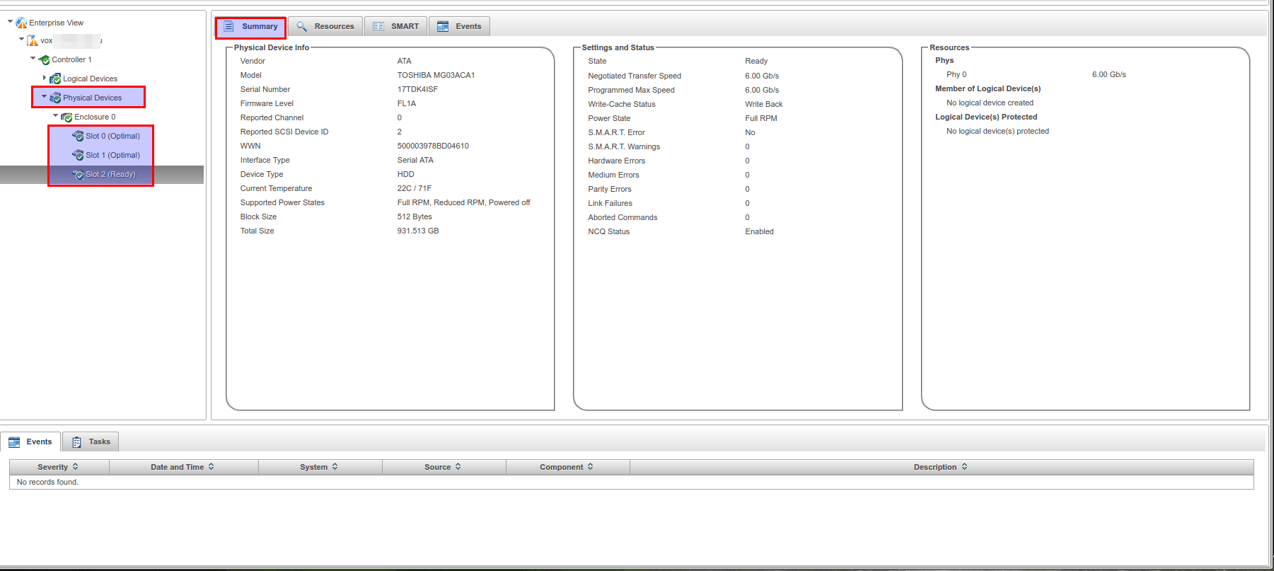
После авторизации в утилите видна страница с общей сводкой по контроллерам, находящимся на мониторинге. Также в виде диаграммы показано соотношение дисков в рейде и свободных дисков.

При переходе в раздел Physical Devices, выбрав устройство можно увидеть слоты (Slot), по сути подключенные на данный момент к контроллеру жесткие диски. Слоты в статусе Ready (на скриншоте это Slot 2), означает, что данный диск не находится ни в одном массиве и не настроен как HotSpare. Также на основной странице можно увидеть различную информацию по выбранному жесткому диску.
Для добавления диска в HotSpare необходимо выбрать соответствующий слот и в разделе Physical Device верхнего меню выбрать Spare Managment. Откроется окно управления spare-устройствами. На первом шаге необходимо выбрать тип Hot Spare. Всего их три:
— Global — назначает диск резервным для всех логических устройств
— Dedicated — назначает диск резервным для одного выбранного логического устройства
— Pooled — назначает диск резервным для выбранного количества логических устройств
В данном примере использован тип Global. Также на данной вкладке можно редактировать HotSpare — пункт Modify, а также убрать диск из HotSpare — Un-asign.
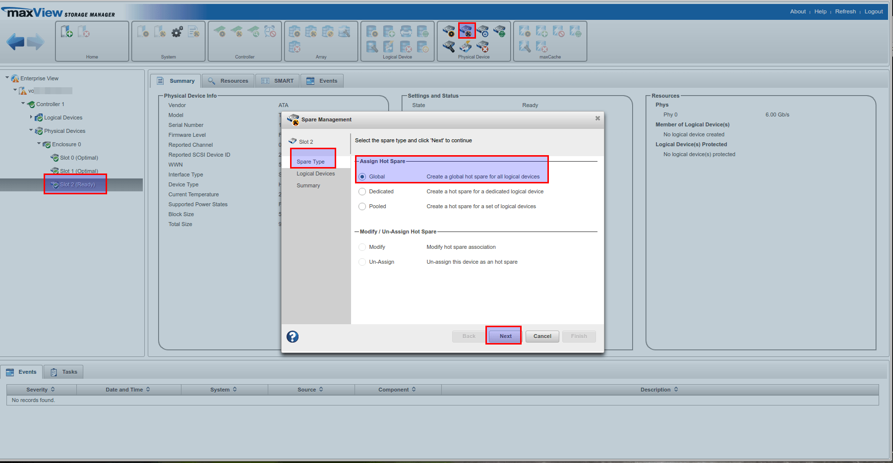
Второй шаг — выбор логического устройства, которое необходимо резервировать, в случае с настройками по типу Global и одним рейд массивом, пропускается — сразу перекидывает на третий шаг: суммарная информация (проверка что корректный массив резервируется) и завершение настройки HotSpare. Для завершения необходимо нажать кнопку Finish.

Если увидели сообщение Assign hot spare operation successful, значит все прошло успешно.
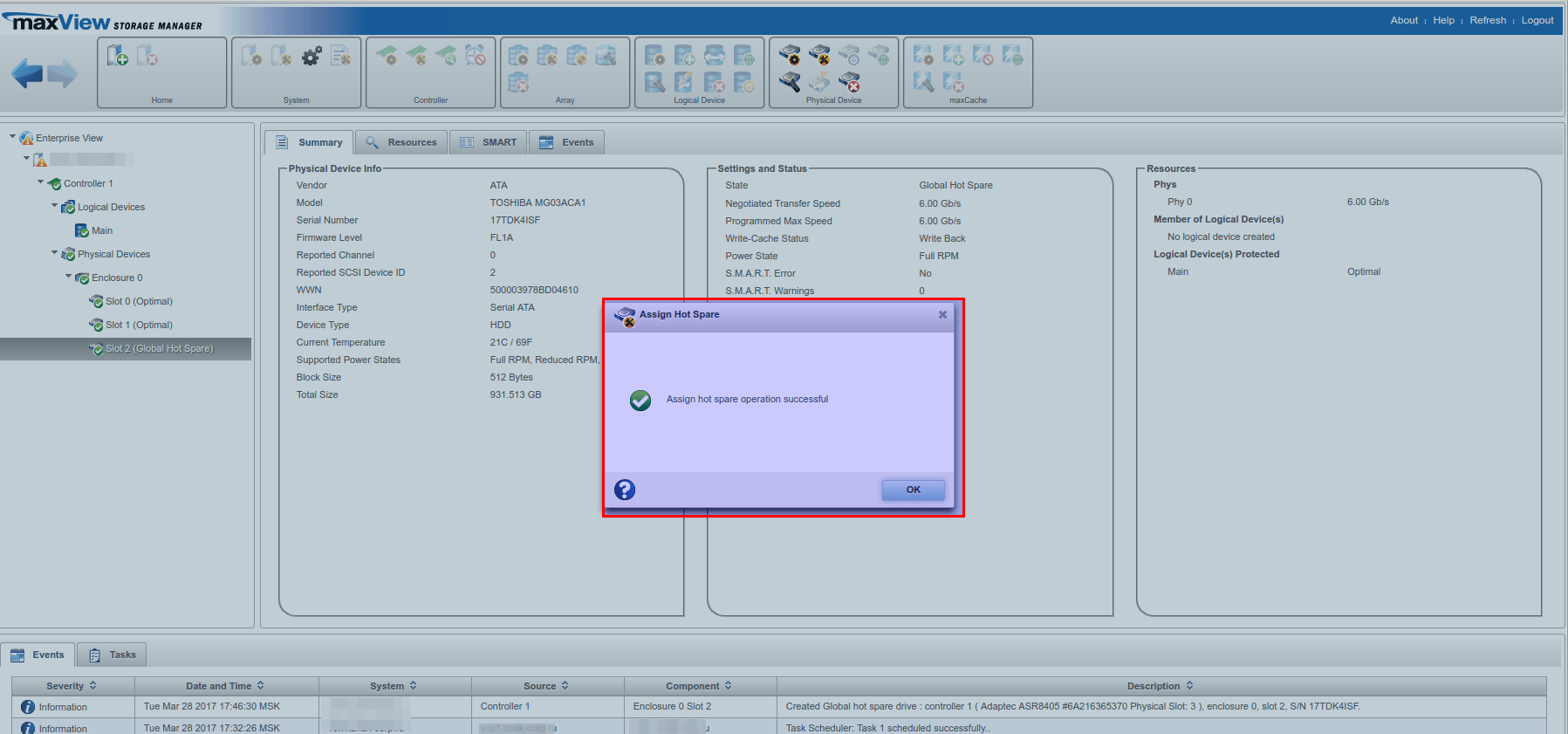
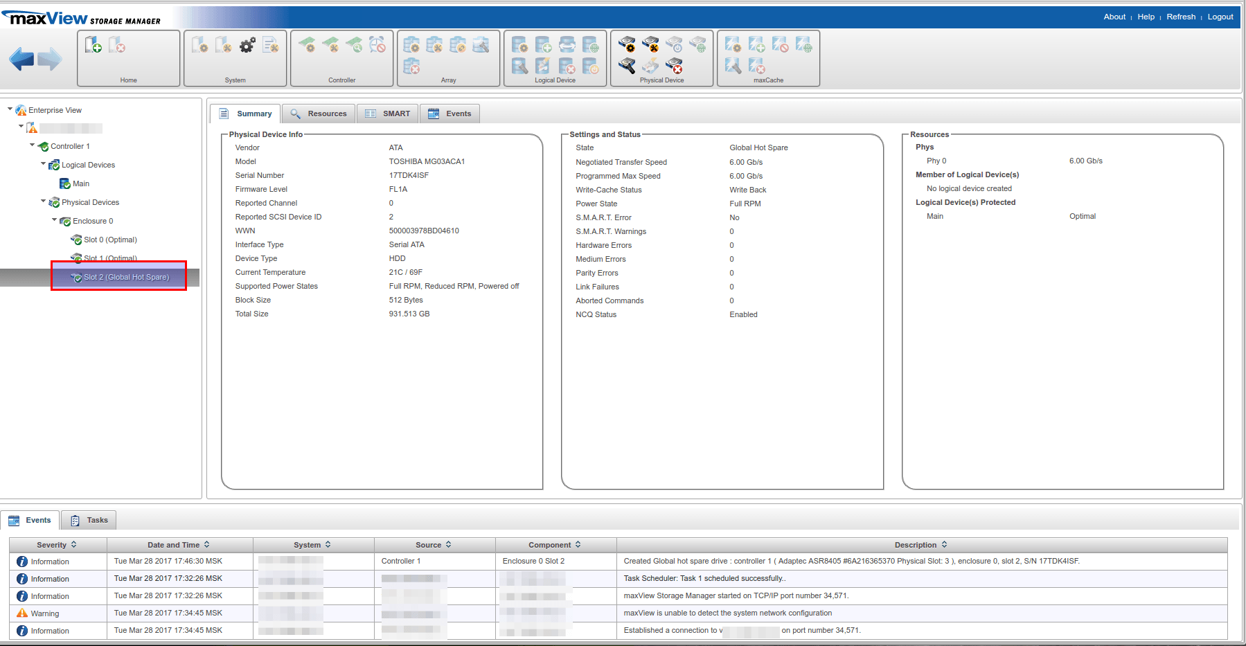
Обозначение резервирующего слота также изменится c ready на указание типа hot spare.
Although you can create an array and logical devices from the Microsemi Adaptec configuration tool available when your computer / server starts up, you can also do it via the «maxView Storage Manager» web interface.
Obviously, this technique is only possible if :
- an operating system is already installed on your computer / server
- you started your computer on a Windows To Go (Windows installation on an USB key)
- you booted from the USB version of maxView Storage Manager
- Create an array and a logical device from maxView Storage Manager
- Initialize the logical device in Windows
- Background logical device parity initialization
- Configure your logical device
1. Create an array and a logical device from maxView Storage Manager
Download and install maxView Storage Manager from the Microsemi site through the «Downloads» tab of your controller page.
If necessary, refer to our tutorial : Adaptec maxView Storage Manager v3 — Presentation.
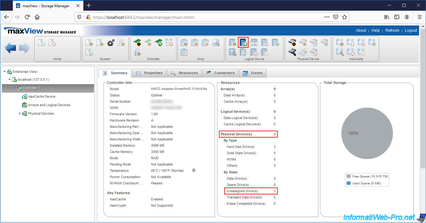
Then, access the «maxView Storage Manager» web interface and select your Microsemi Adaptec controller on the left.
As you can see, in our case :
- there is no array
- there is no logical device
- 3 physical disks (Physical Devices) are connected
- these 3 physical disks are not assigned (Unassigned Drives)
To create a new arrray and a new logical device in it, select your controller on the left, then click the «+» icon in the «Logical Device» section at the top of the page.
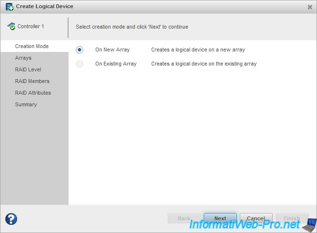
The «Create Logical Device» window appears.
Since we haven’t created an array on our controller yet, we select «On New Array» to create a new array, then click Next.
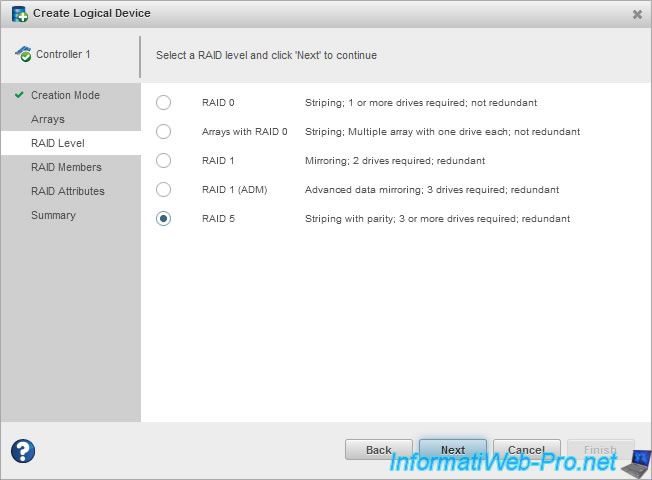
Select the desired RAID Level :
- RAID 0 : requires 2 hard drives and only improves performance by copying half of each data to each hard drive.
The loss of a hard drive will result in the loss of all data on that RAID array. - Arrays with RAID 0 : special mode based on RAID 0 which is not recommended for the security of your data
- RAID 1 : requires 2 hard disks and allows you to copy each data on the 2 hard disks at the same time. This level of RAID only improves the security of your data by supporting the loss of a hard drive.
- RAID 1 (ADM) : same as RAID 1, but with 3 hard disks. The only difference is that this RAID level supports the loss of 2 hard drives instead of 1.
- RAID 5 : requires 3 hard disks and allows to combine performance and security. This level of RAID supports the loss of a single hard drive.
In our case, we are going to create a RAID 5.
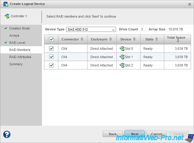
In the «RAID Members» step, select the hard disks that will be members of your array.
Now that your Array is defined, the wizard asks you to create your Logical Device.
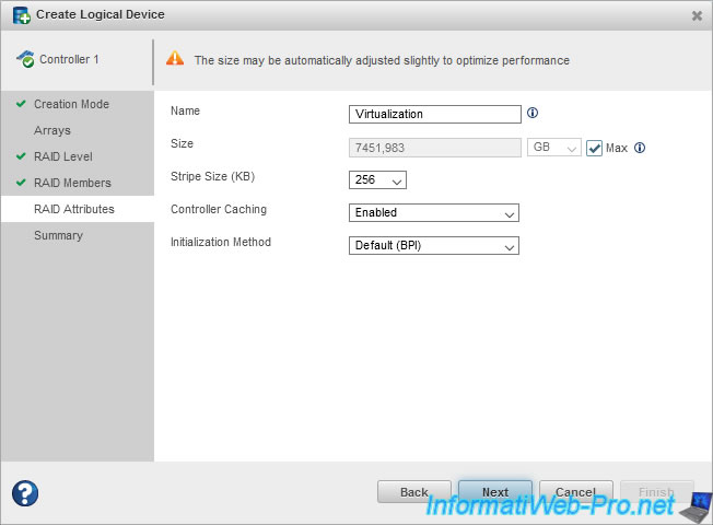
Specify :
- Name : a name to easily find it in Microsemi configuration tools (including : ACU and maxView)
- Size : its size. By default, the «Max» box is checked so that the logical device takes up all the available space on your array
- Stripe Size (KB) : stripe size on each hard drive. So, the amount of data written to one hard drive in the array before moving on to the next.
However, the value to choose depends on the number of physical disks and the RAID level selected previously. So, we recommend that you leave the default. - Controller Caching : allows you to enable or disable the use of read and write caches.
Warning : if you don’t have a battery (eg ASCM-35F) connected to your Microsemi controller, we don’t recommend that you enable it.
This is because in this case, if a power failure occurs while data is in the write cache, it will cause data loss.
Info : this doesn’t apply to the read cache. - Initialization Method :
— Default (BPI) : allows you to instantly use your array, although its performance is reduced during parity initialization performed in the background.
— RPI : parity initialization will be done «offline» and your array will only be available when it’s finished.
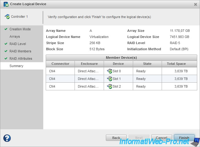
A summary of your Array and Logical Device configuration is displayed.
- Array Name : name automatically assigned to your array. Note that these are the letters of the alphabet (in order) : A, B, C, …
- Logical Device Name : name of your logical device.
- Strip Size : stripe size on hard drives of the array
- Block Size : block size used on hard drives
- Array Size : your array size
- Logical Device Size : the loss of GB is due to the fact that with RAID 5, one of the 3 hard drives selected previously is used only for parity.
- RAID Level : RAID level selected for the array
- Initialization Method : initialization method chosen for parity initialization of your RAID array
Wait a bit.
And the «Create logical device operation successful» message will be displayed.
Wait again.
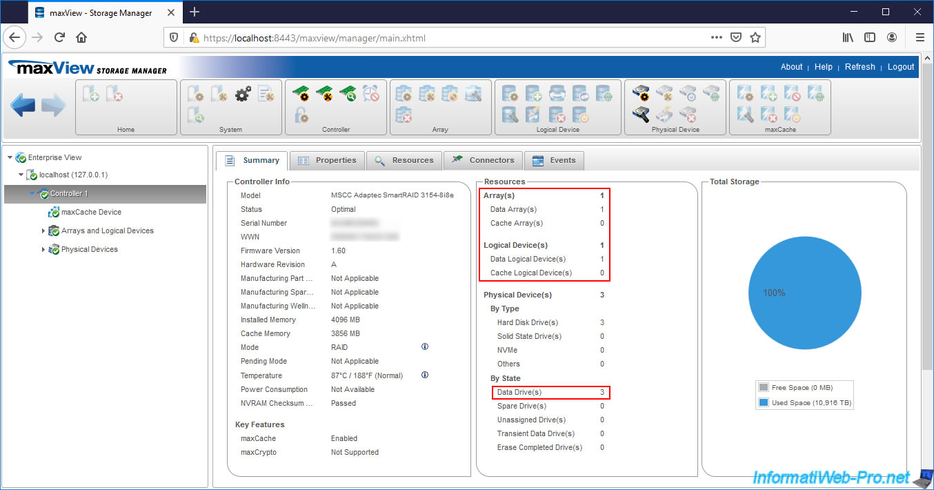
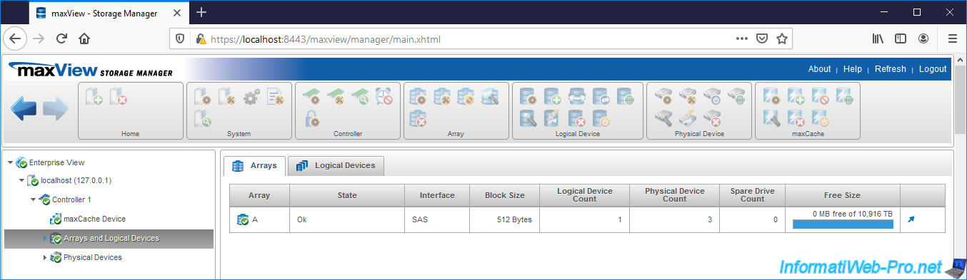
As you can see, our controller has :
- 1 array
- 1 logical device
- 3 physical disks which are used as Data Drives.
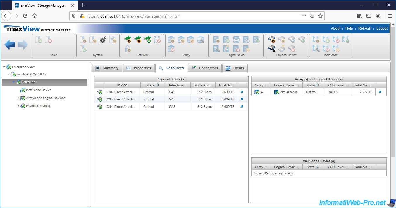
If you go to the «Resources» tab of your controller, you will see that there are :
- 3 physical disks with a SAS interface (connector)
- 1 array («A»)
- 1 logical device («Virtualization») with a RAID level of «RAID 5»
If you look in «Arrays and Logical Devices», you will find your «A» array.
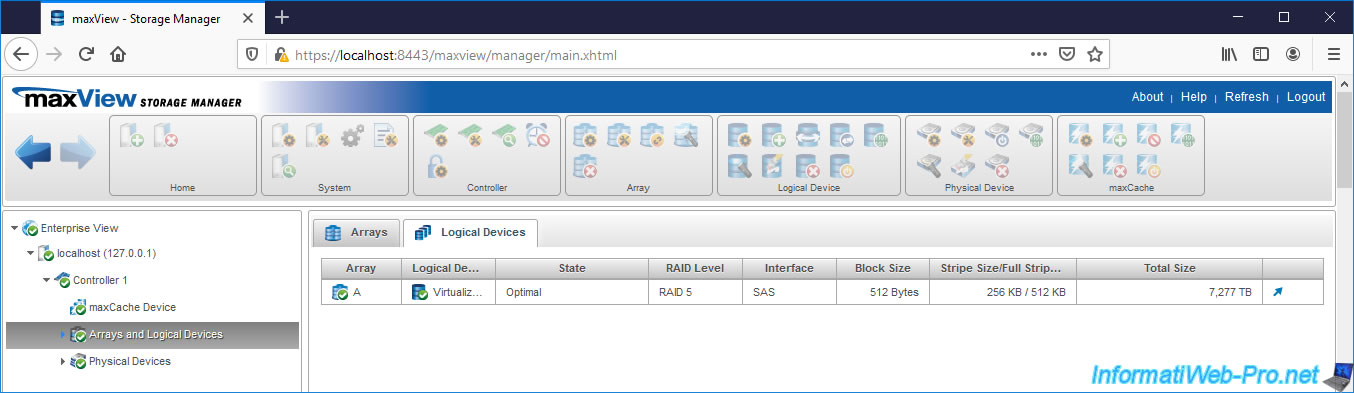
If you go to the «Logical Devices» tab of this «Arrays and Logical Devices» section, you will find your logical device.
Our array contains 3 physical disks and 1 logical device.
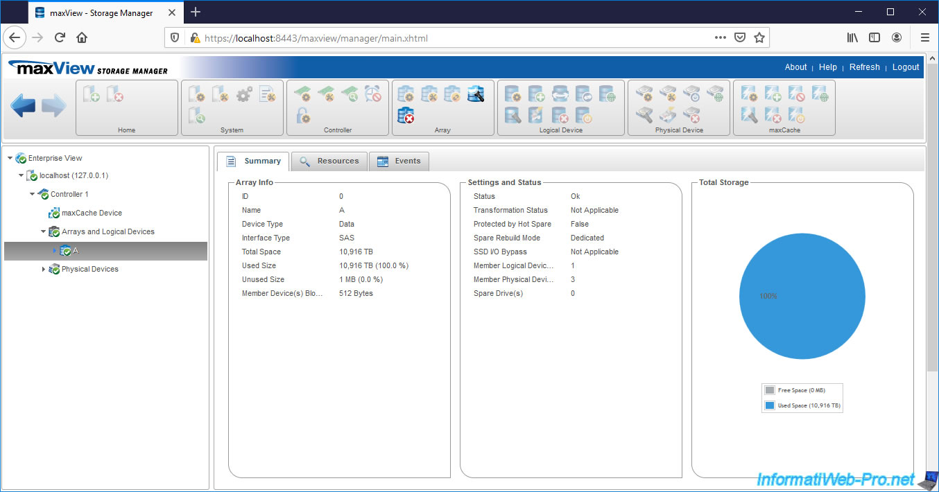
Small difference compared to the configuration tool available at computer startup, when you create a logical device through maxView, you will probably see the value «Queued» for the line «Parity Initialization Status».
The parity initialization is therefore not yet started, but in the queue.
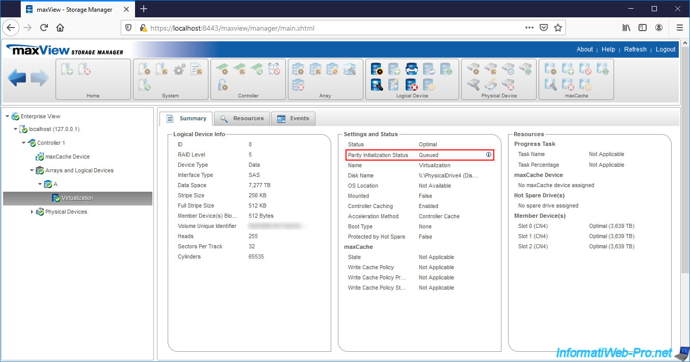
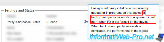
If you click on the little «i» next to this «Queued» status, you will see that maxView tells you that the background parity initialization (of your logical device) is queued and that this will start when I/O (inputs/outputs) are performed on it.
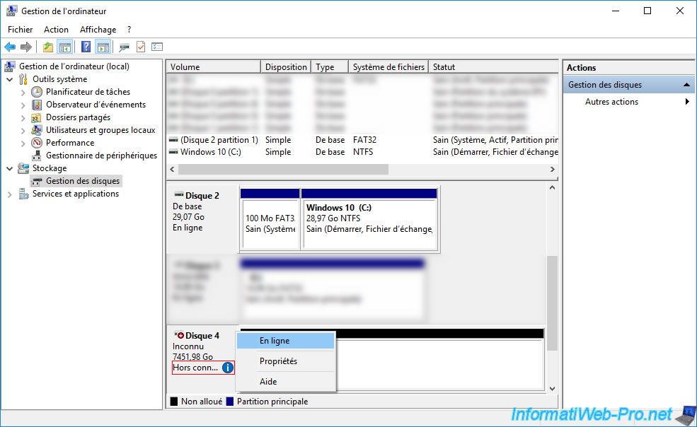
2. Initialize the logical device in Windows
On Windows, open Disk Management and bring the disk online (if you haven’t already).
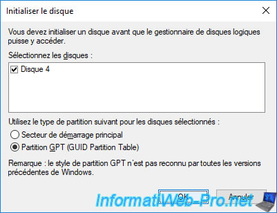
Then, right click «Initialize Disk» on it.
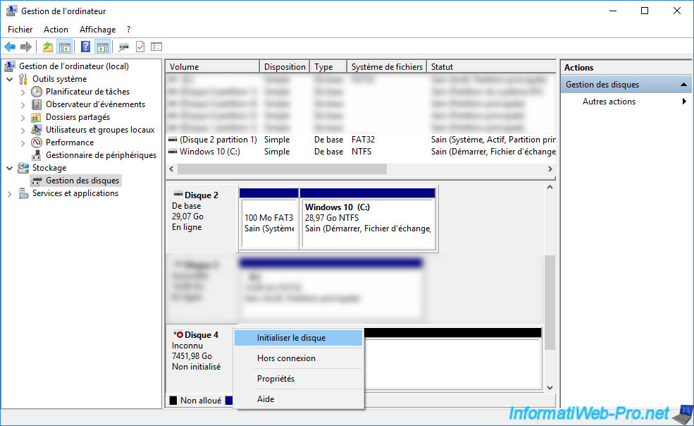
Select the type of partition to use on this disk :
- MBR (Master Boot Record) : corresponds to the MBR which doesn’t support disks larger than 2TB and which limits you to 4 primary partitions
- GPT (GUID Partition Table) : allows you to boot in UEFI on this disk (if applicable) and to support disks of more than 2 TB (the limit being 9.4 Zo), but is not supported by all versions of Windows.
On Windows, GPT is supported from Windows 7 and UEFI booting to it will require a 64-bit (x64) version of Windows.
In our case, since our logical device is around 7 TB in size, we are forced to use GPT.
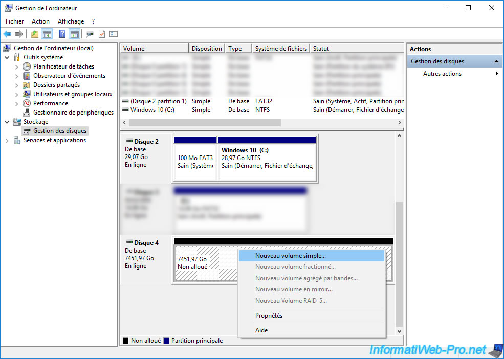
Now that the disk is initialized, you can partition it however you want.
To do this, right click «New simple volume».
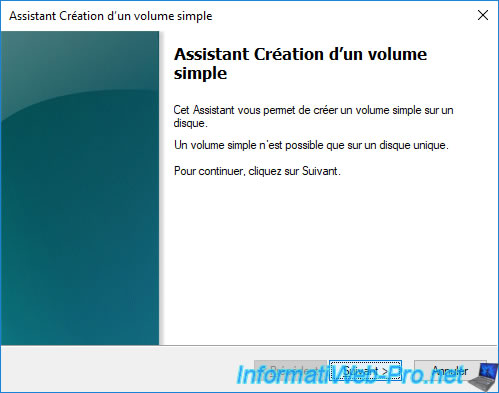
The New Simple Volume Wizard appears.
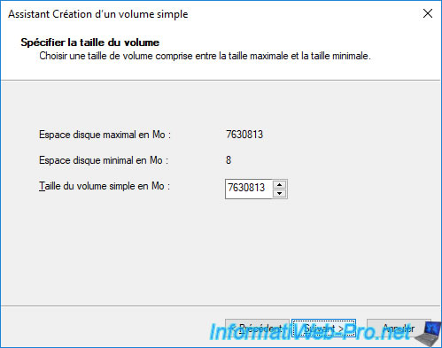
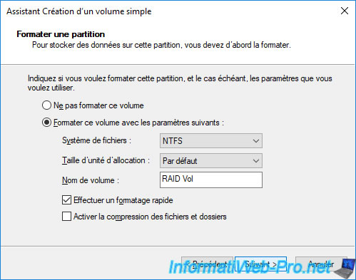
In our case, we will create only one partition (simple volume) to simplify the tutorial.
Enter a name.
In our case : RAID Vol.
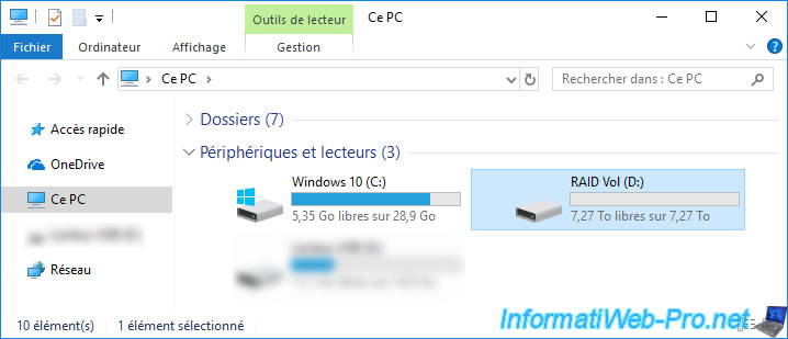
Our logical device has a partition.
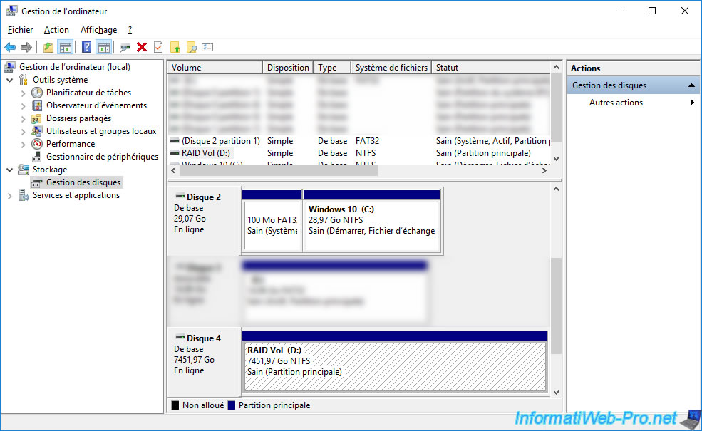
And it appears in the file explorer.
3. Background logical device parity initialization
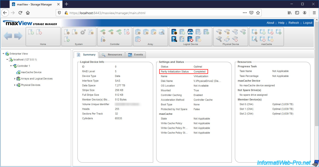
Now that you have started using your logical device, go back to the «maxView» web interface and select your logical device.
As you can see, the Parity Initialization Status is now : In Progress.
In the right column, you will also see the progress of this background parity initialization process.
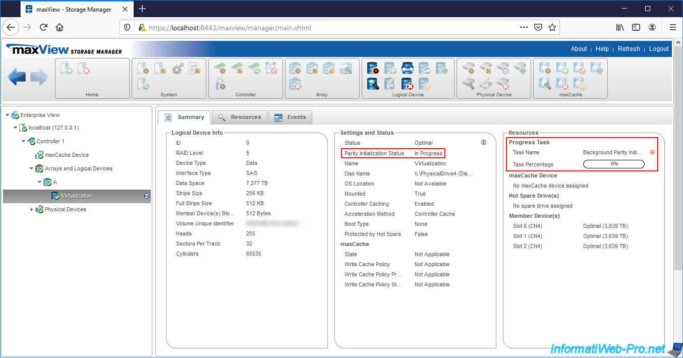
Once the parity of your logical device is initialized, the value of «Parity Initialization Status» will be : Completed.
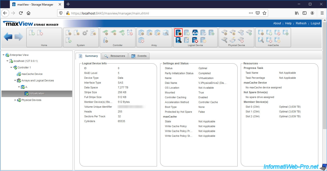
4. Configure your logical device
To configure the properties of your logical device, click on the 1st icon (framed in red on the image) located in the «Logical Device» block.
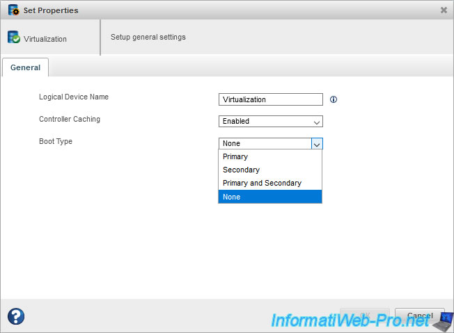
Here, you can :
- Logical Device Name : change its name
- Controller Caching : enable (Enabled) or disable (Disabled) the read and write cache
- Boot Type : enable or disable booting on this logical drive and set it as primary, secondary or both boot drive
Для запуска перестройки RAID-массива вручную, есть три возможных способа.
1. Ручная перестройка с помощью ACU (утилита конфигурации массива) BIOS
Замените вышедший из строя диск новым (такой же или большей емкости). Загрузите систему, нажмите CTRL + A, чтобы получить доступ к служебной программе ACU при загрузке системы. Находясь в служебной программе ACU, выберите «Утилита конфигурации массива», затем нажмите Enter. Выберите «Инициализировать диски» и инициализировать новый диск, который вы добавили в систему.
Затем выберите «Управление массивами». Выделите массив, который необходимо перестроить, и выберите опцию CTRL + S, чтобы управлять горячим резервом для массива, добавьте новый диск в качестве глобального горячего резерва для массива, и перестройка начнется автоматически для деградированного массива. Примечание. Параметр CTRL + S доступен не на всех контроллерах.
2. Ручная перестройка с использованием ARCCONF (утилита командной строки)
Используйте команду ARCCONF ‘setstate’, чтобы назначить вновь добавленный диск в качестве горячего резерва. Введите номер логического устройства, которое находится в деградированном состоянии и требует восстановления. В этом примере новый диск на канале 0 с идентификатором 0 должен быть добавлен в качестве горячего резерва для логического диска 1.
ARCCONF SETSTATE 1 DEVICE 0 0 HSP LOGICAL DRIVE 1
Для получения дополнительной информации о ARCCONF, пожалуйста, обратитесь к Руководству пользователя интерфейса командной строки.
3. Восстановление вручную с помощью Adaptec Storage Manager
Замените вышедший из строя диск новым (такой же или большей емкости). Загрузитесь в операционную систему и войдите в программу Adaptec Storage Manager. В Enterprise View щелкните контроллер с логическим устройством с пониженной производительностью. В разделе «Физические устройства» щелкните только что добавленный жесткий диск и выберите «Действия», затем «Создать выделенный горячий резерв для», затем выберите логическое устройство, которое необходимо восстановить. После этого восстановление логического устройства с ухудшенной производительностью начнется автоматически. Дополнительные подробные инструкции о том, как назначить выделенный «горячий» резерв в Storage Manager, см. В Руководстве пользователя Adaptec Storage Manager.
Ручная перестройка с помощью maxView Storage Manager
Замените вышедший из строя диск новым (такой же или большей емкости). Загрузитесь в операционную систему и войдите в программное обеспечение maxView Storage Manager. В Enterprise View выберите контроллер, затем в дереве Physical Devices выберите только что добавленный диск. На ленте в группе Физические устройства щелкните Управление запасными частями. Выберите «Выделенный», затем нажмите «Готово». После этого автоматически начнется перестройка логического устройства с ухудшенной производительностью. Дополнительные инструкции по созданию и управлению «горячим» резервом см. В Руководстве пользователя maxView Storage Manager.
отсюда
Table of Contents
- MICROCHIP maxView Storage Manager User Guide for Adaptec Smart Storage
- Product Information
- Product Usage Instructions
- Frequently Asked Questions
- About this Guide
- Introduction to maxView Storage Manager
- Installing maxView Storage Manager
- Exploring maxView Storage Manager
- Building Your Storage Space
- Protecting Your Data
- Modifying Your Storage Space
- Working with maxCache Devices
- References
- Read User Manual Online (PDF format)
- Download This Manual (PDF format)
MICROCHIP maxView Storage Manager User Guide for Adaptec Smart Storage
Controllers
Specifications:
- Product Name: maxView Storage Manager
- Model Number: DS00004219G
- Compatibility: Microchip Smart Storage Controllers (SmartRAID/SmartHBA/SmartIOC/SmartROC)
- Platform: Browser-based software application for Windows and Linux
Product Information
maxView Storage Manager is a browser-based software application designed to
assist users in building storage spaces using Microchip Smart Storage
Controllers, disk drives, and enclosures. It allows users to manage stored
data efficiently, whether they have a single controller installed in a server
or multiple controllers, servers, and enclosures.
Key Features:
- Build and manage direct attached storage
- Supports various Microchip Smart Storage Controllers
- Browser-based interface for ease of access
- Allows configuration of storage spaces and data management
Product Usage Instructions
1. Installation:
To start using maxView Storage Manager, follow these steps:
- Download the application from the official website.
- Run the installer and follow the on-screen instructions to complete the installation.
- Launch the application using your preferred web browser.
2. Building Storage Space:
To create a storage space using maxView Storage Manager:
- Login to the application with your credentials.
- Select the option to build a new storage space.
- Follow the prompts to add Smart Storage Controllers, disk drives, and enclosures.
- Configure the storage space according to your requirements.
3. Managing Data:
To manage your stored data with maxView Storage Manager:
- Select the storage space you want to manage.
- View and modify data settings as needed.
- Perform data backups, restores, or any other management tasks through the interface.
Frequently Asked Questions
- Q: Can I use maxView Storage Manager with Adaptec Series 8 RAID controllers?
- A: No, maxView Storage Manager is specifically designed for use with Microchip Smart Storage Controllers (SmartRAID/SmartHBA/SmartIOC/SmartROC).
- Q: Is maxView Storage Manager compatible with Mac operating systems?
- A: No, maxView Storage Manager is currently compatible with Windows and Linux platforms only.
“`
maxViewTM Storage Manager User Guide for Adaptec® Smart Storage Controllers
User Guide
© 2023 Microchip Technology Inc. and its subsidiaries
User Guide
© 2023 Microchip Technology Inc. and its subsidiaries
DS00004219G – 5
About this Guide
1. About this Guide
maxViewTM Storage Manager is a browser-based software application that helps
you build a storage space using Microchip Smart Storage Controllers, disk
drives, and enclosures, and then manage your stored data, whether you have a
single controller installed in a server or multiple controllers, servers, and
enclosures.
This guide describes how to install and use maxView Storage Manager to build
and manage direct attached storage; that is, storage where the controller and
disk drives reside inside, or are directly attached to, the computer accessing
them, similar to the basic configurations shown in the figures below.
Note:This guide focuses on using maxView Storage Manager with Microchip Smart
Storage Controllers (SmartRAID/SmartHBA/SmartIOC/SmartROC). For information
about using maxView Storage Manager with Adaptec Series 8 (legacy) RAID
controllers, see 1.3. How to Find More Information.
Server with Smart Storage controller and disk drives
System running maxView Storage Manager
Network Connection
Server with Smart Storage controller and disk drives
System running maxView Server with Smart Storage controller Storage enclosures
with
Storage Manager
running maxView Storage Manager disk drives installed
1.1 What You Need to Know Before You Begin
This guide is written for data storage and IT professionals who want to create
a storage space for their online data. You should be familiar with computer
hardware, operating system administration, and Redundant Array of Independent
Disks (RAID) technology.
If you are using maxView Storage Manager as part of a complex storage system,
with multiple servers, enclosures and Microchip Smart Storage Controllers, you
should be familiar with network administration, have knowledge of Local Area
Networks (knowledge of storage area networks (SANs) is not required), and be
familiar with the input/output (I/O) technology of the storage devices on your
network, such as Serial ATA (SATA) or Serial Attached SCSI (SAS).
1.2 Terminology Used in this Guide
Because this guide provides information that can be used to manage multiple
Microchip Smart Storage Controllers in a variety of configurations, the
generic term “storage space” is used to refer to the controller(s), disk
drives, and systems being managed with maxView Storage Manager.
For efficiency, the term “component” or “components” is used when referring
generically to the physical and virtual parts of your storage space, such as
systems, disk drives, controllers, and logical drives.
User Guide
© 2023 Microchip Technology Inc. and its subsidiaries
DS00004219G – 6
About this Guide
Many of the terms and concepts referred to in this guide are known to computer
users by multiple names. In this guide, this terminology is used:
· Controller (also known as adapter, board, or I/O card)
· Disk drive (also known as hard disk, hard drive, or hard disk drive)
· Solid State Drive (also known as SSD or non-rotating storage media)
· Logical drive (also known as a logical device)
· Array (also known as a storage pool or container)
· System (also known as a server, workstation, or computer)
· Enclosure (also known as a storage enclosure or disk drive enclosure)
1.3 How to Find More Information
You can find more information about Microchip Smart Storage Controller,
management software, and utilities by referring to these documents, available
for download at start.adaptec.com and the Microchip customer portal at
www.microchip.com/wwwregister/default.aspx:
· SmartIOC 2100/SmartROC 3100 Installation and User’s Guide, SmartIOC 2000
Installation and User’s Guide–Describes how to install drivers and configure
the SmartIOC/SmartROC controller for initial use
· ARCCONF Command Line Utility User’s Guide for Smart Storage Controllers,
SmartIOC 2000 Command Line Utility User’s Guide–Describes how to use the
ARCCONF utility to perform RAID configuration and storage management tasks
from an interactive command line.
· SmartIOC 2100/SmartROC 3100 Software/Firmware Release Notes, SmartIOC 2000
Software/Firmware Release Notes–Provides driver, firmware, and release package
information, and known issues.
· README: maxView Storage Manager & ARCCONF Command Line Utility–Provides
product information, installation notes, and known issues for maxView Storage
Manager and ARCCONF command line utility.
· Microchip Adaptec® SmartRAID 3100 Series and SmartHBA 2100 Series Host Bus
Adapters Installation and User’s Guide–Describes how to install drivers and
configure the SmartRAID 3100 or SmartHBA 2100 Series Host Bus Adapter.
· HBA 1100 Software/Firmware Release Notes–Provides driver, firmware, and
release package information, and known issues.
· SmartHBA 2100 and SmartRAID 3100 Software/Firmware Release Notes–Provides
driver, firmware, and release package information, and known issues.
For information about using maxView Storage Manager with Microchip Adaptec
Series 8 (legacy) RAID controllers, see the maxView Storage Manager User’s
Guide for Adaptec ARC Controllers (CDP-00285-06-A).
User Guide
© 2023 Microchip Technology Inc. and its subsidiaries
DS00004219G – 7
Introduction to maxView Storage Manager
- 2.1
2.2
2.2.1 2.2.2
2.3
Introduction to maxView Storage Manager
This section introduces the maxView Storage Manager software, explains the
concept of “storage space” and provides a checklist of getting-started tasks.
Getting Started
The first part of this guide provides the information needed to install,
start, and begin to use maxView Storage Manager. Follow these general steps:
Step 1: Familiarize yourself with the software components of maxView Storage
Manager, review the system requirements, and study the configuration examples
that illustrate how to build and grow your storage space (described in the
remainder of this chapter).
Step 2: Install maxView Storage Manager on every system that will be part of
your storage space (see 3. Installing maxView Storage Manager).
Step 3: Start maxView Storage Manager and explore its graphical user interface
(see 4. Exploring maxView Storage Manager).
Step 4: Build your storage space (see 5. Building Your Storage Space).
About maxView Storage Manager
maxView Storage Manager is a browser-based software application that helps you
build a storage space for your data, using Microchip RAID controllers, disk
drives, Solid State Drives (SSDs), and enclosures.
With maxView Storage Manager, you can group disk drives into arrays and
logical drives and build in redundancy to protect your data and improve system
performance. You can also use maxView Storage Manager to monitor and maintain
all the controllers, enclosures, and disk drives in your storage space from a
single location.
The maxView Storage Manager GUI, or graphical user interface, runs on most
contemporary Web browsers (for a list of supported browsers, see 2.4. Browser
Support). A software stack comprising a Web server, and Redfish server allows
maxView Storage Manager to communicate with the controller(s) in your storage
space and coordinate activity in your system.
A flexible installation model allows you to install all software components on
a single machine, or distribute components on different machines across your
network, with the maxView Storage Manager GUI and Web server on one machine,
and the Redfish server on others.
About maxView Redfish Server
The maxView Redfish Server is an instance of Nodejs. On Windows and Linux
systems, the Redfish Server manages the hardware, which monitors the
controllers in your system and provide notifications to the maxView Storage
Manager. The maxView Redfish Server is installed automatically with the
maxView Storage Manager.
About the maxView Storage Manager Web Server
The maxView Storage Manager Web Server is an instance of the open-source
Apache Tomcat servlet container. It runs the maxView Storage Manager Web
application, and serves static and dynamic content to the maxView Storage
Manager GUI. The maxView Storage Manager Web Server is installed automatically
with the maxView Storage Manager GUI.
System Requirements
To install maxView Storage Manager, each system in your storage space must
meet these requirements:
· PC-compatible computer with Intel Pentium processor, or equivalent
User Guide
© 2023 Microchip Technology Inc. and its subsidiaries
DS00004219G – 8
2.4
2.5
2.5.1
Introduction to maxView Storage Manager
· At least 4 GB of RAM
· 350 MB of free disk drive space
· One of these operating systems: Microsoft® Windows® Server, Windows SBS,
Windows 10, Windows 8.1 Red Hat® Enterprise Linux
SuSE Linux Enterprise Server
Ubuntu Linux
CentOS
Hypervisors: · VMware vSphere, VMware ESXi
· Citrix XenServer
· Microsoft Hyper-V
See the maxView Storage Manager and ARCCONF Command Line Utility Readme for a
complete list of supported operating system versions.
Note:maxView Storage Manager can also be used before an operating system is
installed.
Browser Support
To run the maxView Storage Manager GUI, each system in your storage space must
be running one of these Web browsers: · Microsoft® Edge browser for Windows 10
· Google® ChromeTM 32 or newer · Mozilla Firefox® 31 or newer
Note:The ideal resolution for the best view of the maxView Storage Manager is
1920 x 1080 ppi. The recommended display scaling setting and browser zoom
setting is 100%.
Typical Storage Space Configurations
The following examples show typical storage spaces that you can build with
maxView Storage Manager. You can grow your storage space as your requirements
change by adding more systems, controllers, disk drives, and enclosures, and
by adding redundant logical drives for protection against data loss.
A Simple Storage Space
This example shows a simple storage space that might be appropriate for a
small business. This storage space includes one RAID controller and three disk
drives installed in a server. For data protection, the disk drives have been
used to build a RAID 5 logical drive.
Business and Customer Data
2.5.2
Server with Smart Storage controller and 3 disk drives
System running maxView Storage Manager
An Advanced Storage Space
This example shows how you can grow your storage space as the requirements of
your application change. On the first server, segments from each disk drive
have been used to build two RAID 5
User Guide
© 2023 Microchip Technology Inc. and its subsidiaries
DS00004219G – 9
Introduction to maxView Storage Manager
logical drives. A second server connected to two 12-disk enclosures has been
added. The additional storage space has been used to create two RAID 50
logical drives. The Administrator of this storage space can create and modify
logical drives and monitor both controllers, disk drives, and enclosures from
a single system running the maxView Storage Manager GUI.
2.5.3
Continuing to Grow Your Storage Space
For more advanced applications, such as high-volume transaction processing in
a “cloud” or data center environment, maxView Storage Manager helps you grow
your storage space to include multiple controllers, storage enclosures, and
disk drives in multiple locations.
In this example, multiple systems, servers, disk drives, and enclosures have
been added to the storage space. The Administrator can create and modify
logical drives and monitor all the controllers, enclosures, and disk drives in
the storage space from any system running the maxView Storage Manager GUI.
User Guide
© 2023 Microchip Technology Inc. and its subsidiaries
DS00004219G – 10
Network Connection
Introduction to maxView Storage Manager
Server running Redfish Server
Storage enclosures with disk drives installed
RAID 50
Local system running maxView Storage Manager
Server with RAID controller and disk
drives installed
RAID 5 RAID 5
RAID 60
Server running Redfish Server
RAID 6
RAID 6
RAID 6
Local system running Redfish Server
Storage enclosures with disk drives installed
User Guide
© 2023 Microchip Technology Inc. and its subsidiaries
DS00004219G – 11
Installing maxView Storage Manager
Installing maxView Storage Manager
This section describes how to install and uninstall maxView Storage Manager on
the supported operating systems. It also describes how to run maxView Storage
Manager from a bootable USB image, before the application is installed on an
operating system.
3.1 Before You Begin the Installation
Complete the following steps before you begin the installation.
3.1.1 Gather Installation Information
Prepare the following information:
· Redfish Server port number: The default port is recommended (8081). If the
default port is not available, another port number will be automatically
assigned. For more information on the Redfish Server, see 2.2.1. About maxView
Redfish Server .
· maxView Web Server port number: The default port is recommended (8443). If
the default port is not available, another port number will be automatically
assigned. For more information on the Web Server, see 2.2.2. About the maxView
Storage Manager Web Server.
Note:You can install maxView Storage Manager over an existing installation if
it is no more than two versions older than the current release. Otherwise, you
must remove the old version first, before beginning a new installation. See
3.7. Uninstalling maxView Storage Manager for details.
3.1.1.1 Check Network Configuration
Check your network configuration to ensure that it meets the prerequisites for
a standard (nonStandalone Mode) installation: · Ensure that the system is
configured with an IP address.
· Ensure that the OS hostname is as per standard.
· Ensure that the hostname-to-IP address mapping is updated in DNS. At
minimum, ensure that the hostname-to-IP mapping is entered in the /etc/hosts
file.
· Ensure that firewall is enabled or network is configured to allow the
connection to withstand for five minutes.
3.1.2
3.2
Download the Installation Package
Complete these steps to download the installation package for your operating
system(s): 1. Open a browser window, then type storage.microsemi.com/en-
us/support/ in the address bar.
2. Select your controller family and controller model.
3. Select Storage Manager Downloads, then select the appropriate installer
package from the list; for instance, maxView Storage Manager for Windows x64
or maxView Storage Manager for Linux.
4. Click Download Now and accept the license agreement.
5. When the download completes, extract the package contents to a temporary
location on your machine. Note:See the Release Notes for a complete list of
installer packages for the supported operating systems.
Installing on Windows
This section describes how to install maxView Storage Manager on Windows
systems. Note:You need administrator privileges to install maxView Storage
Manager. For details on verifying privileges, see your operating system
documentation.
User Guide
© 2023 Microchip Technology Inc. and its subsidiaries
DS00004219G – 12
Installing maxView Storage Manager
1. Open Windows Explorer or My Computer, then change to the directory where
the Windows installer package is located (see 3.1.2. Download the Installation
Package for details).
2. Double click the setup program for your operating system version:
Option
Description
Windows 64-bit
setup_asm_x64.exe
The Installation wizard opens. 3. Click Next to begin the installation.
The License Agreement screen on the Installation wizard appears. 4. Select I
accept the terms in the license agreement option, then click Next. 5. Accept
or modify the default server ports in the maxView Storage Manager
Configuration screen:
a) Web Server Port: 8443 (default) b) Redfish Server Port: 8081 (default)
6. To disable remote system management from the GUI, click the Standalone
Mode check box.
Note:In Standalone mode, maxView Storage Manager displays the system name as
“localhost” and events as “127.0.0.1/localhost”.
7. To install maxView in desktop web application mode, select the Desktop Web
Application check box.
Note:In Desktop Web Application mode, there are no services installed. The
remote system management from the GUI is disabled.
8. Click Next, then click OK to verify the Web Server port and the Redfish
Server port numbers. The Direct Attached Storage Setup screen appears on the
Installation wizard.
9. Ensure that GUI and/or Redfish Server is selected. Optionally, select CLI
Tools. Click Next.
User Guide
© 2023 Microchip Technology Inc. and its subsidiaries
DS00004219G – 13
Installing maxView Storage Manager
10. Click Install to begin the installation.
11. Repeat these steps to install maxView Storage Manager on every Windows
system that will be part of your storage space.
When the installation is complete you receive a confirmation message and the
maxView Storage Manager icon is placed on your desktop.
3.3 Installing on Red Hat, Citrix XenServer, CentOS, or SuSE Linux
This section describes how to install maxView Storage Manager on systems
running Red Hat Linux, CentOS, XenServer, or SuSE Linux. For a list of
supported Linux operating systems, see 2.3. System Requirements.
1. Open a shell window, then change to the directory where the Linux
installer package is located (see 3.1.2. Download the Installation Package for
details).
2. Run the .bin file for your operating system version (x.xx-xxxxx=version-
build number):
Option
Description
Linux 64-bit
./StorMan-X.XX-XXXXX.x86_64.bin
3. When prompted for configuration details, enter one of the following:
Desktop Web Application Mode: [default: No] Note:Desktop web application mode
does not install the services. It disables remote system management from the
GUI.
Standalone Mode: [default: No] Note:Standalone Mode disables remote system
management from the GUI. maxView Storage Manager displays the system name as
“localhost”, and events as “127.0.0.1/localhost”.
4. Repeat these steps to install maxView Storage Manager on every Linux
system that will be part of your storage space. When the installation
completes a confirmation message is displayed and the maxView Storage Manager
icon is placed on your desktop.
3.4 Installing on Debian or Ubuntu Linux
This section describes how to install maxView Storage Manager on systems
running Debian or Ubuntu Linux.
1. Open a shell window, then change to the directory where the Linux
installer package is located (see 3.1.2. Download the Installation Package for
details).
2. Install the .deb package for your operating system version (x.xx-xxxxx
=version-build number).
User Guide
© 2023 Microchip Technology Inc. and its subsidiaries
DS00004219G – 14
Installing maxView Storage Manager
Option Linux 64-bit
Description dpkg -i StorMan-X.XX-XXXXX_amd64.deb
3. When prompted for configuration details, enter the following: Standalone
Mode: [default: No] Note:Standalone Mode disables remote system management
from the GUI. maxView Storage Manager displays the system name as “localhost”,
and events as “127.0.0.1/localhost”.
Desktop Web Application Mode: [default: No] Note:Desktop web application mode
does not install the services. It disables the remote system management from
the GUI.
4. Repeat these steps to install maxView Storage Manager on every Debian and
Ubuntu Linux system that will be part of your storage space.
5. Before upgrading/re-installing maxView Storage Manager on an existing
Ubuntu/Debian installation, enable the upgrade switch before installing the
maxView .deb package: export maxView_Upgrade=true dpkg -i StorMan-*.deb
When the installation is complete you receive a confirmation message and the
maxView Storage Manager icon is placed on your desktop.
3.5 Installing on VMware 7.x and ESXi 8.x
Use the following procedure to install the .zip files for a VMware ESXi
system. Perform the installation from a remote system running a Telnet/SSH
client. Use a terminal emulator to access the ESXi server remotely.
1. Copy the following files from the installer download location to the /tmp
directory on your local ESXi.
AdaptecArcconf_x.xx.xxxxx-MIS.x.x.x.xxxxxxxx_xxxxxxxx.zip
AdaptecRedfish_x.xx.xxxxx-MIS.x.x.x.xxxxxxxx_xxxxxxxx.zip
The AdaptecArcconf_x.xx.xxxxx-MIS.x.x.x.xxxxxxxx_xxxxxxxx.zip is for command
line communication. The
AdaptecRedfish_x.xx.xxxxxMIS.x.x.x.xxxxxxxx_xxxxxxxx.zip is for remote
management communication
2. Check for existing installation of ARCCONF. esxcli software vib list |
grep arcconf
3. Remove the existing ARCCONF package. esxcli software vib remove -n arcconf
When the package is removed, you receive the message “Reboot Required: true.”
4. Check for an existing installation of adaptecredfishserver. esxcli
software vib list | grep adaptecredfishserver
5. Remove the existing adaptecredfishserver package. esxcli software vib
remove -n adaptecredfishserver
When the package is removed, you receive the message “Reboot Required: true.”
6. Set the installation acceptance level to VMwareAccepted: esxcli software
acceptance set -level=VMwareAccepted
7. Install the ARCCONF package. esxcli software vib install -d
/tmp/AdaptecArcconf_x.xx.xxxxxMIS.x.x.x.xxxxxxxx_xxxxxxxx.zip
When the package is installed, you receive the message “Reboot Required:
true.”
8. Install the adaptecredfishserver package.
User Guide
© 2023 Microchip Technology Inc. and its subsidiaries
DS00004219G – 15
Installing maxView Storage Manager
esxcli software vib install -d
/tmp/AdaptecRedfish_x.xx.xxxxxMIS.x.x.x.xxxxxxxx_xxxxxxxx.zip When the package
is installed, you receive the message “Reboot Required: true.”
9. To add a remote system, see 14.2. Managing Remote Systems.
10. Execute the following command in ESXI 8.x to permit the write access to
root user in order to add system and perform operations from maxView GUI.
esxcli daemon entitlement add -r -w -p root
Note:arc-cim-provider is not supported for VMware.
Note:There are specific arcconf and adaptecredfishserver packages for each
VMware versions. Use the appropriate package for installation.
3.6 Running maxViewTM Storage Manager from a Bootable USB Image
Running maxView Storage Manager from a bootable USB image allows you to
configure your controller before installing the operating system. The
procedure consists of three basic steps: 1. Download the bootable USB image
from the Microchip web site
2. Create a “live” image on a USB flash drive Note:We recommend using Rufus
bootable USB create (http://rufus.akeo.ie/).
3. Boot from the USB flash drive, login to maxView Storage Manager and
configure your controller
The bootable USB image is not a substitute for running maxView Storage Manager
as an installed application. Many of the features and functions described in
this guide are not available when you run maxView Storage Manager from a
bootable USB image. Use the bootable USB image only to configure your
controller before installing an operating system.
Note:Before you begin, ensure that your system is set up to boot from a USB
drive. Check the system BIOS to see if the USB drive is included in the boot
sequence. (For more information, see your system’s documentation.) You will
need a USB drive with at least 2 GB of storage to complete this task. To run
the bootable USB image, the target machine must have at least 4 GB of memory.
To run maxView Storage Manager from a bootable USB image:
1. Download the bootable USB image: a) Open a browser window, then type
storage.microsemi.com/en-us/support/ in the address bar.
b) Select your controller family and controller model.
c) Select Storage Manager Downloads.
d) Download the bootable USB image (zip file archive).
e) Extract the contents of the bootable image archive file to a temporary
location. The archive contains one file: the maxView Storage Manager bootable
iso image.
2. Create a “live” image on the USB drive: a) Run the USB Creator utility
setup program at http://rufus.akeo.ie/.
b) Start USB Creator from the Windows All Programs menu.
c) In the Use Existing Live CD field, click Browse, then locate and select the
maxView Storage Manager bootable ISO image.
d) In the Target Device field, select the USB flash drive (e:, for instance).
e) Click Create Live USB.
3. Insert the USB drive on the machine you want to configure. The Boot menu
opens in a shell window.
4. Select Launch maxView from the menu.
User Guide
© 2023 Microchip Technology Inc. and its subsidiaries
DS00004219G – 16
3.7
3.7.1 3.7.2 3.7.3
3.7.4
Installing maxView Storage Manager
After a minute or so, the maxView Storage Manager login screen opens in a
browser window. Note:If you prefer to configure the controller from the
command line, select Launch arcconf from the Boot menu, then enter root, with
no password, for the login credentials.
5. Enter root/root for the login credentials.
6. Continue with 5.4. Creating Arrays and Logical Drives.
While loading the BootUSB image, if you get the “NMI watchdog: BUG soft lockup
– cpu#0 stuck for 22s!” error message then execute one of the following step
in the “GNU GRUB” bootloader screen:
1. Perform the boot operation using the Troubleshoot –> Start
Mscc_Boot_usb in basic graphics mode.
2. Manually set “nomodeset” by selecting ‘e’ command and add “nomodeset” in
‘linuxefi’ line.
Uninstalling maxView Storage Manager
To uninstall maxView Storage Manager, follow the instructions for your
operating system.
Uninstalling from Windows
To uninstall maxView Storage Manager from a Windows system, use the Add or
Remove Programs tool in the Control Panel. All maxView Storage Manager
components are uninstalled. When the uninstall process is complete, you
receive a confirmation message and the maxView icon is removed from your
desktop.
Uninstalling from Red Hat, Citrix XenServer, CentOS, or SuSE Linux
This section describes how to uninstall maxView Storage Manager from systems
running Red Hat, XenServer, CentOS, or SuSE Linux. 1. Type the command rpm -e
StorMan
When the uninstall process is complete, you receive a confirmation message and
the maxView icon is removed from your desktop.
Uninstalling from Ubuntu Linux
This section describes how to uninstall maxView Storage Manager from systems
running Ubuntu Linux. 1. Type the command dpkg -r StorMan
2. Type the command to uninstall maxView after the upgrade export
maxView_Upgrade=false dpkg -r storman
When the uninstall process is complete, you receive a confirmation message and
the maxView icon is removed from your desktop.
Uninstalling from VMware 7.x
Use the following procedure to remove maxView Storage Manager from a VMware
ESXi 7.x system. 1. Log in with the user name: root
2. List the installed packages: esxcli software vib list | grep arcconf
esxcli software vib list | grep adaptecredfishserver
3. Remove the arcconf package: esxcli software vib remove -n arcconf
4. Remove the adaptecredfishserver: esxcli software vib remove -n
adaptecredfishserver
5. Reboot the system.
User Guide
© 2023 Microchip Technology Inc. and its subsidiaries
DS00004219G – 17
Installing maxView Storage Manager
To verify that maxView Storage Manager is uninstalled, repeat Step 2. If there
are no results, the software is uninstalled successfully.
User Guide
© 2023 Microchip Technology Inc. and its subsidiaries
DS00004219G – 18
Exploring maxView Storage Manager
4. Exploring maxView Storage Manager
This section familiarizes you with the main features of the maxView Storage
Manager graphical user interface. It describes how to start and login to
maxView Storage Manager. It also explains how to get help and log out of
maxView Storage Manager when you are finished working with the application.
4.1 Starting maxView Storage Manager and Logging In
The procedure for starting and logging in to maxView Storage Manager is the
same for all operating systems with a graphical desktop. You can login as the
Administrator, with full management-level access to your storage space, or as
a Standard user, with restricted access to your storage space (see 4.2.
Working in maxView Storage Manager for more information about access
permissions). 1. On the desktop, double-click the maxView Storage Manager
desktop icon.
The login window opens in the default browser.
Note:If you do not have an icon for maxView Storage Manager on your desktop,
open a browser window, then type this URL in the address bar and press Return:
https:// 127.0.0.1:8443/maxview/manager/login.xhtml.
2. For full management-level access to your storage space, enter the
Administrator account username and password for your operating system. For
Standard-level access to your storage space, enter your regular network login
credentials. Then click Login. The maxView Storage Manager main window opens.
4.2 Working in maxView Storage Manager
You can perform most tasks in maxView Storage Manager by:
· Selecting storage components in the Enterprise View (controllers, hard
drives, logical drives, and so on)
· Clicking icons on the ribbon, at the top of the maxView Storage Manager main
window
· Working with information in the Storage Dashboard and Chart View
· Checking status in the Event Log and Task Log
If you are logged in as the Administrator, you have full access to manage and
modify the components of your storage space, using all of the features of
maxView Storage Manager. If you are logged in as a Standard user, you have
restricted “view-only” access to your storage space, with limited ability to
perform non-destructive operations, as described in the table below.
Note:maxView Storage Manager allows you to give Standard users Administrator
privileges. For details, see 14.5. Granting Standard Users Admin Privilege.
Standard users can: Rescan controllers Save activity logs
Standard users can’t: Create arrays and logical drives Modify arrays and
logical drives
User Guide
© 2023 Microchip Technology Inc. and its subsidiaries
DS00004219G – 19
………..continued
Standard users can:
Standard users can’t:
Identify physical devices, logical devices, Delete arrays and logical drives
and enclosures
Silence alarms
Perform data migrations
View component properties on the Storage Dashboard
Clear the controller configuration
Exploring maxView Storage Manager
4.3 Overview of the Main Window
The main window of maxView Storage Manager has three main panels–left, right,
and bottom– plus the ribbon, at the top of the window.
The left panel always shows the Enterprise View. The bottom panel shows the
Event Log and Task Log. The right panel shows the Storage Dashboard and Chart
View. Different information appears in the right panel depending on which
component is selected in the Enterprise View.
In example below, a controller is selected in the Enterprise View, and the
right panel displays the Storage Dashboard for the controller, with a chart
view of its storage space.
4.3.1
You can resize the panels and scroll horizontally or vertically as needed, to
view more or less information.
The Enterprise View
The Enterprise View is an expandable “tree” that shows the physical and
logical components of your storage space. The Enterprise View lists the local
system (the system you’re working on) and any remote systems that you have
logged in to from the local system. (See 5.2.1. Local’ orRemote’? for more
information.) It also lists the maxCache Devices in your system. Note:maxCache
is not supported on all Adaptec Smart Storage Controllers. See the Readme for
more information. For more information about maxCache, see 8. Working with
maxCache Devices.
User Guide
© 2023 Microchip Technology Inc. and its subsidiaries
DS00004219G – 20
Local System
Exploring maxView Storage Manager
Remote System
Expand a system in the Enterprise View to see its controllers, arrays, logical
drives (“devices”), physical drives, enclosures, backplanes, and maxCache
devices. In the following figure a controller is expanded in the Enterprise
View, revealing the physical and logical devices associated with that
controller.
User Guide
© 2023 Microchip Technology Inc. and its subsidiaries
DS00004219G – 21
By selecting a controller in the Enterprise View…
…the disk drives or enclosures and disk drives connected to it and the arrays
and logical drives created with those disk drives appear in the Physical and
Logical Devices trees.
Exploring maxView Storage Manager
You can perform most tasks in maxView Storage Manager by selecting a component
in the Enterprise View, such as a controller or disk drive, then using the
related commands on the ribbon, as described in the section below.
4.3.1.1 What do the Enterprise View Icons Mean?
Icon
Description System with controller and directly attached disk drives or
enclosures
Controller
Enclosure
Logical drive (encrypted)1
1 A lock in the Enterprise View means that the device is encrypted. For more
information, see 9. Working with maxCryptoTM Devices.
User Guide
© 2023 Microchip Technology Inc. and its subsidiaries
DS00004219G – 22
………..continued
Icon
Description
maxCache Device (healthy)2
Array (healthy)
Hard disk drive
Solid State Drive (SSD)
SMR (Shingled Magnetic Recording) drive3
Connector or other physical device
Exploring maxView Storage Manager
4.3.2
The Ribbon
Most tasks in maxView Storage Manager are available from the ribbon, at the
top of the main window. The ribbon replaces toolbars and menus in maxView
Storage Manager to help quickly find the commands to complete a task.
There are two formats of ribbon view available: · Classic Ribbon View
· Simplified Ribbon View
The following screenshot shows the Classic Ribbon View:
The classic ribbon is organized into groups of related tasks for Systems,
Controllers, Arrays, Logical Devices, Physical Devices, and maxCache Devices.
The Home group (on the left) provides commands for working with remote systems
(see 14.2. Managing Remote Systems). Active options on the ribbon vary,
depending on which type of component is selected in the Enterprise View.
For instance, if a controller is selected in the Enterprise View, the
following options are activated:
· Create Logical Drive in the Logical Device group · Spare Management in the
Physical Device group · Create maxCache Device in maxCache group (if the
controller supports maxCache) · All options in the Controller group
If an array is selected in the Enterprise View, options in the Array group are
highlighted; selecting a disk drive highlights options in the Physical Device
group; and so on.
The following image shows the Simplified Ribbon View:
2 A green check mark in the Enterprise View means that the device is healthy
with no problems
or issues. For more information, see 15.2. Identifying a Failed or Failing
Component. 3 Not supported on all controllers. See the Readme for more
information.
User Guide
© 2023 Microchip Technology Inc. and its subsidiaries
DS00004219G – 23
4.3.3
Exploring maxView Storage Manager
The icon highlighted on the top right corner is used to switch between Classic
view and Simplified View.
For instance, if a controller is selected in the Enterprise view, only the
applicable ribbon icon is visible and activated. Note:You can switch between
Classic View and Simplified View at any time.
For a description of the icons on the ribbon, see 22. Icons At-a-Glance.
The Storage Dashboard
When you select a component in the Enterprise View, maxView Storage Manager
displays detailed information about that component on the Storage Dashboard.
Occupying the largest portion of the main window in maxView Storage Manager,
the Storage Dashboard provides status information, physical and logical device
properties, resources, usage statistics, and reliability indicators for hard
drives and SSDs. It also provides a chart view of free and used space in your
system.
For more information about the types of information provided on the Storage
Dashboard for each component in your storage space, see 13.2.3. Viewing
Component Status in the Storage Dashboard; also see 4.5. Revealing More Device
Information .
4.4 Checking System Status from the Main Window
maxView Storage Manager includes an Event Log and Task Log for at-a-glance
status and activity information for all managed systems. The Event Log
provides status information and messages about activity (or events) occurring
in your storage space. The Task Log provides information about current
processes in your storage space, such as rebuilding a logical device. Single-
click any event or task to see more information in an easier-to-read format. .
Warning- and Error-level icons appear next to components in the Enterprise
View affected by a failure or error, creating a trail, or rapid fault
isolation, that helps you identify the source of a problem when it occurs. See
15.2. Identifying a Failed or Failing Component for more information.
User Guide
© 2023 Microchip Technology Inc. and its subsidiaries
DS00004219G – 24
Exploring maxView Storage Manager
If your storage space includes a drive enclosure with a temperature sensor,
temperature, fan, and power module status is displayed on the Storage
Dashboard (see 13.2.3.2. Monitoring Enclosure Status).
For more information about checking status from the main window, see
Monitoring Status and Activity.
4.5 Revealing More Device Information
Reveal more information about disk drive, array, and logical drive usage in
the storage space (including maxCache Devices) with the Resources view on the
Storage Dashboard.
To reveal disk drive usage by logical drive (and vice-versa), select a
controller in the Enterprise View, then open the Resources tab on the Storage
Dashboard. The following figure shows that clicking on a logical drive
displays its member disk drives and spares; similarly, clicking on a physical
disk displays which array (if any) it belongs to. In the following figure, the
disk in Slot 1 and Slot 2 belongs to Array A.
Note:Click the Arrow icons, on the right side of the Resources table, to jump
to that resource in the Enterprise View tree.
User Guide
© 2023 Microchip Technology Inc. and its subsidiaries
DS00004219G – 25
4.6 Getting Help
Exploring maxView Storage Manager
maxView Storage Manager provides online help that includes conceptual
information and descriptions of on-screen items and dialog boxes, in addition
to step-by-step instructions for completing tasks.
To open the online help, click the Help button at the upper-right corner of
the main window.
Click here to open the Help window.
For help with a dialog box or wizard, click the question-mark icon, in the
lower corner of the dialog box, for help with that specific procedure.
Click here for help with this procedure
For help with individual options in the Set Properties dialog box (for
controllers, logical drives, and physical drives), or specific information
fields on the Storage Dashboard, mouse over any field or option name for a
brief description of that option.
4.7 Logging Out of maxView Storage Manager
To log out of maxView Storage Manager: 1. In the Enterprise View, click on the
local system. 2. Click the Logout button at the upper-right corner of the main
window:
Click here to log out
You are logged out of maxView Storage Manager and the main window is closed.
User Guide
© 2023 Microchip Technology Inc. and its subsidiaries
DS00004219G – 26
Building Your Storage Space
- 5.1
5.2
5.2.1
Building Your Storage Space
Follow the instructions in this section to choose a management system, log in
to each system in your storage space, and create arrays and logical drives.
Note:Before beginning the tasks in this chapter, ensure that maxView Storage
Manager is installed on every system that will be part of your storage space.
Overview
To build your storage space, complete these steps:
1. Choose at least one management system (see Choosing a Management System).
2. Start and log in to maxView Storage Manager on the management system (see
4.1. Starting maxView Storage Manager and Logging In ).
3. Log in to all other systems from the management system (see 5.3. Logging
into Remote Systems from the Local System).
4. Create arrays and logical drives for all systems in your storage space
(see 5.4. Creating Arrays and Logical Drives).
As your storage requirements change, you can add systems, controllers, and
disk drives, then modify the arrays and logical drives in your storage space
by following the instructions in 7. Modifying Your Storage Space.
Choosing a Management System
Designate at least one system as a management system from which you will
manage the storage on all systems in your storage space.
The management system can be any system on your network that has a video
monitor and can run the maxView Storage Manager GUI and Web server.
Local’ orRemote’?
Whenever you’re working in maxView Storage Manager, the system that you’re
working on is the local system. All other systems in your storage space are
remote systems. Local’ andremote’ are relative terms, as shown in the
following figure–when you are working on system A (local system), system B is
a remote system; when you are working on system B (local system), system A is
a remote system.
For the purposes of this guide, the `local system’ is the management system.
User Guide
© 2023 Microchip Technology Inc. and its subsidiaries
DS00004219G – 27
Building Your Storage Space
A
B
maxView Storage Manager
A
Local logged in to remote
Redfish Server
B
Redfish Server
Local logged in to remote
maxView Storage Manager
5.2.2
5.3
Logging in on the Local System
To log in on the local system, see 4.1. Starting maxView Storage Manager and
Logging In .
Logging into Remote Systems from the Local System
Once maxView Storage Manager is running on all systems in your storage space,
you can log into the remote systems from the local system.
Once you have logged in to a remote system, it automatically appears in the
Enterprise View each time you start maxView Storage Manager on the local
system. You can work with a remote system’s controllers, disk drives, and
logical drives as if they were part of your local system.
To log in to a remote system:
1. On the ribbon, in the Home group, click Add System.
The Add System window opens, showing a list of “discovered” systems; that is,
systems on your network that are running the Redfish.
Note: The list of discovered systems appear only when Auto Discovery option is
enabled in maxView. For more details on how to change the auto-discovery
settings, see 14.2.4. Changing the AutoDiscovery Settings.
2. Select the systems you want to add to the Enterprise View, then enter the
systems’ login credentials (username/password) in the space provided. The
Single Sign-On option gets enabled if more than one system is selected. Also,
ensure that the selected systems should have same login credentials.
User Guide
© 2023 Microchip Technology Inc. and its subsidiaries
DS00004219G – 28
Building Your Storage Space
Note:You can add a system manually if you don’t see the system in the list.
For more information, see Manually Adding a Remote System .
3. Click Add. maxView Storage Manager connects to the remote system(s) and
adds them to the list of managed systems in the Enterprise View.
For more information about working with remote systems, see Managing Remote
Systems.
5.4 Creating Arrays and Logical Drives
maxView Storage Manager provides a wizard to help you create, or configure,
the arrays and logical drives in your storage space. You can choose from two
configuration methods:
· Create logical drive on new array–Helps you set the RAID level for the
logical drive, group disk drives and SSDs, determine logical drive size and
other advanced settings. For instructions, see 5.4.1. Creating a Logical Drive
on a New Array.
· Create logical drive on existing array–Helps you select an array on which to
create the logical drive, set the RAID level, group disk drives and SSDs,
determine logical drive size and configure advanced settings. For
instructions, see 5.4.2. Creating a Logical Drive on an Existing Array.
If maxCrypto is enabled, you can create encrypted or plaintext volumes. (For
more information, see 9. Working with maxCryptoTM Devices.)
Notes: 1. Mixing SAS and SATA drives within the same logical drive is not
supported. The wizard does not
allow you to select a combination of SAS and SATA drive types. 2. maxView
Storage Manager supports SMR HA4 and SMR DM drives for all RAID levels.
However,
mixing SMR and PMR5 drives within the same logical drive is not supported.
maxView Storage Manager displays a warning message if you try to create a
logical drive using a combination of SMR and PMR device types.
4 SMR: Shingled Magnetic Recording. HA: Host Aware (backward compatible with
standard HDD).
DM: Device Managed (backward compatible with standard HDD). 5 PMR:
Perpendicular Magnetic Recording; standard HDD recording technology.
User Guide
© 2023 Microchip Technology Inc. and its subsidiaries
DS00004219G – 29
5.4.1
Building Your Storage Space
Creating a Logical Drive on a New Array
An array must be created before creating a logical drive. Use the On New Array
configuration method to step through the process of creating a logical drive
on a new array, setting the RAID level, and configuring other settings.
To create a logical drive on an existing array, see 5.4.2. Creating a Logical
Drive on an Existing Array.
By default, maxView Storage Manager uses all available disk space to maximize
the capacity of a new logical drive.
To create a logical drive on a new array:
1. In the Enterprise View, select a system, then select a controller on that
system. 2. On the ribbon, in the Logical Device group, click Create Logical
Device.
3. When the wizard opens, select On New Array, then click Next.
4. Select a RAID level for the logical drive, then click Next.
User Guide
© 2023 Microchip Technology Inc. and its subsidiaries
DS00004219G – 30
Building Your Storage Space
Note:Not all RAID levels are supported by all controllers. (See the Release
Notes for more information.) See Selecting the Best RAID Level for more
information about RAID levels.
5. Select the disk drives you want to include in the logical drive, then
click Next. Be sure the drive type is the same for all drives (SAS or SATA,
not mixed), and that you select the right number of drives for the RAID level
you selected.
Note: For details on SED support operations on a new array while creating a
logical device, see 5.6.1. Create Logical Device.
6. (Optional) In the RAID Attributes panel, customize the logical drive
settings.
User Guide
© 2023 Microchip Technology Inc. and its subsidiaries
DS00004219G – 31
Building Your Storage Space
You can: · Enter a name for the logical drive. Names can include any
combination of letters, numbers,
and spaces.
· Set the size and unit of measure for the logical drive. (By default, a new
logical drive uses all available disk space.)
· Change the stripe size–the amount of data, in bytes, written per disk in the
logical drive. (The default stripe size usually provides the best
performance.)
· Enable or disable controller caching.
· Set the initialization method to Default or Build. The initialization method
determines how the logical drive is prepared for reading and writing, and how
long initialization will take: Default–Initializes parity blocks in the
background while the logical drive is available for access by the operating
system. A lower RAID level results in faster parity initialization.
Build–Overwrites both the data and parity blocks in the foreground. The
logical drive remains invisible and unavailable to the operating system until
the parity initialization process completes. All parity groups are initialized
in parallel, but initialization is faster for single parity groups (RAID 5).
RAID level does not affect performance during Build initialization.
Note:Not all initialization methods are available for all RAID levels.
· Create an encrypted or plaintext logical drive (for more information, see 9.
Working with maxCryptoTM Devices)
7. Click Next, then review the array and logical drive settings. This example
shows a RAID 0 logical drive ready to be created on Array A.
User Guide
© 2023 Microchip Technology Inc. and its subsidiaries
DS00004219G – 32
Building Your Storage Space
5.4.2
8. Click Finish. maxView Storage Manager builds the array and logical drive.
Use the Event Log and Task Log to track build progress.
9. If you have other disk drives or available disk space and want to create
additional arrays on the controller, repeat Steps 28 .
10. Repeat Steps 19 for each controller in your storage space. 11. Partition
and format your logical drives. See 5.4.3. Partitioning and Formatting Your
Logical
Drives.
Creating a Logical Drive on an Existing Array
After creating an array, continue to build the storage space by creating more
logical drives on that array. Use the On Existing Array configuration method
to step through the process of creating a logical drive on an existing array,
setting the RAID level, and configuring other settings.
To create a logical drive on a new array, see 5.4.1. Creating a Logical Drive
on a New Array.
By default, maxView Storage Manager uses all available disk space to maximize
the capacity of a new logical drive.
Note: Logical drives can be added/created by selecting the existing array from
the Enterprise view.
To create a logical drive on an existing array:
1. In the Enterprise View, select a system, then select a controller on that
system. 2. On the ribbon, in the Logical Device group, click Create Logical
Device.
3. When the wizard opens, select On Existing Array, then click Next.
User Guide
© 2023 Microchip Technology Inc. and its subsidiaries
DS00004219G – 33
Building Your Storage Space
4. Select the array on which to create the logical drive, then click Next.
Note: For details on SED support operations on an existing array while
creating a logical device, see 5.6.1. Create Logical Device.
5. Select a RAID level for the logical drive, then click Next.
User Guide
© 2023 Microchip Technology Inc. and its subsidiaries
DS00004219G – 34
Building Your Storage Space
Note:Not all RAID levels are supported by all controllers. (See the Release
Notes for more information.) See Selecting the Best RAID Level for more
information about RAID levels.
6. (Optional) In the RAID Attributes panel, customize the logical drive
settings.
You can:
· Enter a name for the logical drive. Names can include any combination of
letters, numbers, and spaces.
· Set the size and unit of measure for the logical drive. (By default, a new
logical drive uses all available disk space.)
· Change the stripe size–the amount of data, in bytes, written per disk in the
logical drive. (The default stripe size usually provides the best
performance.)
· Enable or disable controller caching.
· Set the initialization method to Default or Build. The initialization method
determines how the logical drive is prepared for reading and writing, and how
long initialization will take: Default–Initializes parity blocks in the
background while the logical drive is available for access by the operating
system. A lower RAID level results in faster parity initialization.
User Guide
© 2023 Microchip Technology Inc. and its subsidiaries
DS00004219G – 35
Building Your Storage Space
Build–Overwrites both the data and parity blocks in the foreground. The
logical drive remains invisible and unavailable to the operating system until
the parity initialization process completes. All parity groups are initialized
in parallel, but initialization is faster for single parity groups (RAID 5).
RAID level does not affect performance during Build initialization.
Note:Not all initialization methods are available for all RAID levels.
· Create an encrypted or plaintext logical drive (for more information, see 9.
Working with maxCryptoTM Devices)
7. Click Next, then review the array and logical drive settings. This example
shows a RAID 0 logical drive to be created on Array A.
5.4.3 5.4.4
8. Click Finish. maxView Storage Manager builds the logical drive on the
array. Use the Event Log and Task Log to track build progress.
9. If you have other disk drives or available disk space and want to create
more logical drives on an existing array, repeat Steps 2-8.
10. Repeat Steps 1-9 for each controller in your storage space.
11. Partition and format your logical drives. See 5.4.3. Partitioning and
Formatting Your Logical Drives.
Partitioning and Formatting Your Logical Drives
The logical drives you create appear as physical disk drives on your operating
system. You must partition and format these logical drives before you can use
them to store data. Note:Logical drives that have not been partitioned and
formatted cannot be used to store data.
Refer to your operating system documentation for more information.
Creating Logical Drives on Other Systems in Your Storage Space
If maxView Storage Manager and Microchip Smart Storage controllers are
installed on more than one system, continue building your storage space as
follows:
· From each individual system, log in to maxView Storage Manager and repeat
the steps to create logical drives on new or existing arrays, or
User Guide
© 2023 Microchip Technology Inc. and its subsidiaries
DS00004219G – 36
5.5
5.5.1
Building Your Storage Space
· From your local system (the system you’re working on), log in to all other
systems in your storage space as remote systems (see Logging into Remote
Systems), then repeat the steps to create logical drives on new or existing
arrays, or
· From your local system, create a server template file and deploy the
configuration to the remote systems in your storage space (see Deploying
Servers).
Controller Support for 4K Drives
This section describes how to use the maxView GUI with 4K drives to create and
modify logical drives and spares.
Creating a Logical Drive
A logical drive is created using 4K drives. 512-byte drives cannot be mixed
with 4K drives. This can be done by selecting the Device Type as HDD SATA 4K
or HDD SAS 4K. This will ensure that only HDD SATA 4K or HDD SAS 4K devices
are displayed.
User Guide
© 2023 Microchip Technology Inc. and its subsidiaries
DS00004219G – 37
5.5.2
Building Your Storage Space
Moving a Logical Drive
A 4K SAS or 4K SATA logical device can be moved to another array of 4K SAS or
4K SATA drives, but cannot be moved to an array with 512-byte drives.
· Moving to a new array: all SATA and SAS 4K drives that are available to move
to a new array are listed.
· Moving to an existing array: if the logical device has already been created
in a different array using 4K drives, then the option will move a logical
device to the existing array of the same block size SAS/SATA 4K drives. Only
arrays created using 4K drives will be listed (512-byte arrays will not
User Guide
© 2023 Microchip Technology Inc. and its subsidiaries
DS00004219G – 38
be listed).
Building Your Storage Space
5.5.3 Modifying a Logical Drive
Arrays created using 4K drives can be modified.
User Guide
© 2023 Microchip Technology Inc. and its subsidiaries
DS00004219G – 39
Building Your Storage Space · Moving drive(s): Moving a drive from one array
to another array using the same interface type.
For example, if an array is created using 4K SATA drives, then you can move a
drive(s) from that array to a separate array that also uses 4K SATA drives.
· Changing drive types: Changing the drive interface type from SAS to SATA or
from SATA to SAS. For example, if an array is created using 4K SAS drives, you
can change the drive type to 4K SATA drives only.
5.5.4 Assigning Spares at the Array Level
Spares for 4K logical drives can be assigned at the array level.
User Guide
© 2023 Microchip Technology Inc. and its subsidiaries
DS00004219G – 40
Building Your Storage Space
1. Dedicated Hot Spare: If the array/logical device is created using 4K SATA
drives, then only the 4K SATA devices can be assigned as spares.
2. Auto Replace Hot Spare: The process is the same as the Dedicated Hot
Spare.
5.5.5 Assigning Spares at the Physical Device Level
Spares for 4K logical drives can be assigned at the physical device level.
User Guide
© 2023 Microchip Technology Inc. and its subsidiaries
DS00004219G – 41
Building Your Storage Space
· If array/logical device is created with 4K SAS drives, then only logical
devices that were created with 4K SAS drives are listed.
Notes: · maxCache cannot be created using 4K SATA drives.
· 512-byte maxCache cannot be assigned to 4K logical devices.
· Drive interface types and drive block sizes cannot be mixed. For example,
SATA drives and SAS drives of the same block size cannot be mixed; 512-byte
drives and 4K drives of the same interface type cannot be mixed.
User Guide
© 2023 Microchip Technology Inc. and its subsidiaries
DS00004219G – 42
5.6
5.6.1
Controller Support for SED
Building Your Storage Space
An SED (Self Encrypting Drive) is a type of hard drive that automatically and
continuously encrypts the data on the drive without any user interaction. If
an SED gets locked, the volumes on the array may become degraded or
inaccessible. If this occurs, unlock the SED(s) and warm-boot the server.
This section lists the operations that are allowed/not allowed based on the
array status, logical device status, physical device’s SED security status,
and SED qualification status.
Create Logical Device
On Existing Array
Create logical device operation on an existing array will be blocked when the
target Array has the following status:
Array Status One or more logical drives undergoing or failed SED qualification
Create Array Allowed/Not Allowed Creation not allowed
On New Array
The following table lists the physical device SED security status and SED
qualification status, based on which the SED drives must be included in the
new Array creation.
SED Security Status Locked Not Applicable Not Applicable
SED Qualification Status Not Applicable Failed Locking Enabled Failed Range
Length Set
Create Array Allowed/Not Allowed Creation not allowed Creation allowed
Creation allowed
5.6.2
Modify Array
Add Drives
When the Array status is OK, adding the SED drives to the array is not allowed
based on the physical device SED security status and SED qualification status:
SED Security Status
SED Qualification Status
Locked Not Applicable Not Applicable
Not Applicable Failed Locking Enabled Failed Range Length Set
When the Array status is OK, adding the SED drives to the array is not allowed
based on the physical device Original Factory State (OFS) and SED ownership
status.
Original Factory State (OFS)
SED Ownership Status
False False False
Otherwise Owned MCHP Owned, Foreign Otherwise Owned, Foreign
Add drives operation to an existing array will be blocked when the Array has
the following status:
Array Status One or more logical drives undergoing or failed SED qualification
Has Logical Drive with Foreign SED
Move Drives
User Guide
© 2023 Microchip Technology Inc. and its subsidiaries
DS00004219G – 43
Building Your Storage Space
When the Array status is OK, changing an existing drive(s) with SED drives of
same type in the array is not allowed based on the physical device SED
security status and SED qualification status:
SED Security Status
SED Qualification Status
Locked Not Applicable Not Applicable
Not Applicable Failed Locking Enabled Failed Range Length Set
When the Array status is OK, adding the SED drives to the array is not allowed
based on the physical device Original Factory State (OFS) and SED ownership
status:
Original Factory State (OFS) False False False
SED Ownership Status Otherwise Owned MCHP Owned, Foreign Otherwise Owned,
Foreign
Move drives operation on array will be blocked when the Array has the
following status:
Array Status One or more logical drives undergoing or failed SED qualification
Has logical drive with foreign SED
Change Drive Type
When the Array status is OK, changing existing drives of different type with
SED drives of different type in the array is not allowed based on the
following physical device SED security status and SED qualification status:
SED Security Status
SED Qualification Status
Locked Not Applicable Not Applicable
Not Applicable Failed Locking Enabled Failed Range Length Set
When the Array status is OK, adding the SED drives to the array is not allowed
based on the physical device Original Factory State (OFS) and SED ownership
status:
Original Factory State (OFS) False False False
SED Ownership Status Otherwise Owned MCHP Owned, Foreign Otherwise Owned,
Foreign
Change drive type operation on array will be blocked when the Array has the
following status:
Array Status One or more logical drives undergoing or failed SED qualification
Has Logical Drive with Foreign SED
Heal Array
When the Array status is “Has Failed Physical Device”, replacing failed drives
with SED drives in the array is not allowed based on the following physical
device SED security status and SED qualification status:
User Guide
© 2023 Microchip Technology Inc. and its subsidiaries
DS00004219G – 44
SED Security Status Locked Not Applicable Not Applicable
SED Qualification Status Not Applicable Failed Locking Enabled Failed Range
Length Set
Building Your Storage Space
5.6.3
When the Array status is OK, adding the SED drives to the array is not allowed
based on the physical device Original Factory State (OFS) and SED ownership
status:
Original Factory State (OFS) False False False
SED Ownership Status Otherwise Owned MCHP Owned, Foreign Otherwise Owned,
Foreign
Modify Array ribbon icon should be disabled on the following Array status:
Array Status Has Logical Drive with Foreign SED
Move Logical Device
To a New Array
When the Array status is OK, moving a logical device with new set of SED
drives is not allowed based on the following physical device SED security
status and SED qualification status:
SED Security Status
SED Qualification Status
Locked Not Applicable Not Applicable
Not Applicable Failed Locking Enabled Failed Range Length Set
When the Array status is OK, adding the SED drives to the array is not allowed
based on the physical device Original Factory State (OFS) and SED ownership
status:
Original Factory State (OFS) False False False
SED Ownership Status Otherwise Owned MCHP Owned, Foreign Otherwise Owned,
Foreign
To an Existing Array Move logical device to an existing array operation on
logical device will be blocked when the Array has the following status:
Array Status
One or more logical drives undergoing or failed SED qualification Has Logical
Drive with Foreign SED
Move logical device ribbon icon should be disabled on the following logical
device status:
Logical Device Status SED Qual Failed SED Qual In Progress SED Locked
User Guide
© 2023 Microchip Technology Inc. and its subsidiaries
DS00004219G – 45
5.6.4
Building Your Storage Space
Spare Management
When the Array status is OK, assigning a spare to an array with SED drives is
not allowed based on the following physical device SED security status and SED
qualification status:
SED Security Status
SED Qualification Status
Locked Not Applicable Not Applicable
Not Applicable Failed Locking Enabled Failed Range Length Set
5.6.5
When the Array status is OK, adding the SED drives to the array is not allowed
based on the physical device Original Factory State (OFS) and SED ownership
status:
Original Factory State (OFS) False False False
SED Ownership Status Otherwise Owned MCHP Owned, Foreign Otherwise Owned,
Foreign
Spare management ribbon icon should be disabled on the array based on the
following array status:
Array Status One or more logical drives undergoing or failed SED qualification
Has Logical Drive with Foreign SED
Spare Management ribbon icon should be disabled on the following Array status:
Array Status Has Logical Drive with Foreign SED
maxCache
On Existing Array Create logical device operation on an existing array is
blocked when the target Array has the following status:
Array Status
One or more logical drives undergoing or failed SED qualification Has Logical
Drive with Foreign SED
Create maxCache operation on existing cache array should be blocked when the
target Array has the following status:
Cache Array SED Encryption Status Encrypted=True Encrypted=False
Logical Device SED Encryption Status Encrypted=False Encrypted=True
On New Array
The SED drives can be included in the new Array creation based on the
following physical device SED security and SED qualification status.
SED Security Status Locked Not Applicable Not Applicable
SED Qualification Status Not Applicable Failed Locking Enabled Failed Range
Length Set
User Guide
© 2023 Microchip Technology Inc. and its subsidiaries
DS00004219G – 46
Building Your Storage Space
When the Array status is OK, adding the SED drives to the array is not allowed
based on the physical device Original Factory State (OFS) and SED ownership
status:
Original Factory State (OFS) False False False
SED Ownership Status Otherwise Owned MCHP Owned, Foreign Otherwise Owned,
Foreign
User Guide
© 2023 Microchip Technology Inc. and its subsidiaries
DS00004219G – 47
Protecting Your Data
6. Protecting Your Data
In addition to standard RAID (RAID 0, RAID 1, RAID 5, RAID 10), Microchip
controllers provide additional methods of protecting your data, including
dedicated and auto-replace hot spare drives.
A hot spare is a disk drive or SSD (Solid State Drive) that automatically
replaces any failed drive in a logical drive, and can subsequently be used to
rebuild that logical drive. (For more information, see 15.3. Recovering from a
Disk Drive Failure.)
6.1 Dedicated Spare or Auto-Replace Spare?
A dedicated hot spare is assigned to one or more arrays. It will protect any
redundant logical drive on those arrays.
After using a dedicated hot spare to rebuild a failed logical drive, data is
moved back to its original location, using a process called copyback, once the
controller detects that the failed drive has been replaced. Once the data is
copied back, the hot spare becomes available again. You must create an array
before you can assign a dedicated hot spare to protect it. To assign a
dedicated hot spare, see 6.3. Assigning a Dedicated Hot Spare.
An auto-replace hot spare is assigned to a specific array. It will protect any
redundant logical drive on that array. After using an auto-replace spare to
rebuild a failed logical drive, it becomes a permanent part of the array. You
must create an array before you can assign an auto-replace hot spare to
protect it. To assign an auto-replace hot spare, see 6.4. Assigning an Auto-
Replace Hot Spare.
6.2 Hot Spare Limitations
· Hot spares protect redundant logical drives only. To protect non-redundant
logical drives, set the spare activation mode of the controller to predictive
activation.
· You cannot create a hot spare from a disk drive that is already part of an
array.
· You should select a disk drive that is at least as big as the smallest disk
drive in the array that it might replace.
· You must designate a SAS hot spare drive for an array comprised of SAS disk
drives, and a SATA hot spare drive for an array comprised of SATA disk drives.
· You can designate a SMR HA6 or SMR DM drive for all hot spare types. A SMR
drive cannot protect a PMR7 drive, or vice-versa.
6.3 Assigning a Dedicated Hot Spare
A dedicated hot spare is assigned to one or more arrays. It will protect any
redundant logical drive on those arrays.
6 SMR: Shingled Magnetic Recording. HA: Host Aware (backward compatible with
standard HDD). DM: Device Managed (backward compatible with standard HDD).
7 PMR: Perpendicular Magnetic Recording; standard HDD recording technology.
User Guide
© 2023 Microchip Technology Inc. and its subsidiaries
DS00004219G – 48
Protecting Your Data Note:You must create the array before you can assign a
dedicated hot spare to protect it. To assign a dedicated spare: 1. In the
Enterprise View, select a controller, an array on that controller, or a Ready
physical drive. 2. On the ribbon, in the Physical Device group, click Spare
Management.
The Spare Management wizard opens. 3. Select the Dedicated spare type, then
click Next.
4. If you selected a physical drive in the Enterprise view, select the arrays
you want to protect with a dedicated spare, then click Next.
User Guide
© 2023 Microchip Technology Inc. and its subsidiaries
DS00004219G – 49
Protecting Your Data
5. If you selected an array in the Enterprise view, select the physical
drive(s) you want to dedicate as hot spares, then click Next. For details on
SED support operations, see 5.6.4. Spare Management. (See 6.2. Hot Spare
Limitations for help selecting drives.)
6. Review the summary of dedicated spares and protected arrays, then click
Finish.
6.4 Assigning an Auto-Replace Hot Spare
An auto-replace hot spare is assigned to a specific array. After using an
auto-replace spare to rebuild a failed logical drive, it becomes a permanent
part of the array. To assign an auto-replace hot spare to an array: 1. In the
Enterprise View, select an array on that controller.
Note:The auto-replace option is not available, if you select an array with a
non-redundant logical device when the controller’s “spare activation mode” is
set to “failure activation”. However, when you select a physical device
itself, the option is available only if one or more auto-replace spares
already exist. Otherwise, you can just assign Dedicated spares in the wizard.
2. On the ribbon, in the Physical Device group, click Spare Management.
The Spare Management wizard opens. 3. Select the Auto-Replace spare type, then
click Next.
User Guide
© 2023 Microchip Technology Inc. and its subsidiaries
DS00004219G – 50
Protecting Your Data
4. If you selected a controller in the Enterprise view, select the array you
want to protect with an auto-replace spare, then click Next.
5. Select the physical drive(s) you want to assign as auto-replace hot
spares, then click Next. For details on SED support operations, see 5.6.4.
Spare Management. (See 6.2. Hot Spare Limitations for help selecting drives.)
User Guide
© 2023 Microchip Technology Inc. and its subsidiaries
DS00004219G – 51
Protecting Your Data
6. Review the summary of auto-replace spares and protected arrays, then click
Finish.
6.5 Removing a Hot Spare
You can remove a dedicated or auto-replace hot spare from an array. Removing
the last hot spare from an array returns the drive to the Ready state. You may
want to remove a hot spare to: · Make disk drive space available for another
array or logical drive. · Convert an auto-replace hot spare into a dedicated
hot spare. · Remove the `hot spare’ designation from a drive that you no
longer want to use as a spare. To remove a hot spare: 1. In the Enterprise
View, select an array or an existing hot spare drive. 2. On the ribbon, in the
Physical Device group, click Spare Management.
The Spare Management wizard opens. 3. Select Un-Assign, then click Next. (Un-
Assign is preselected for an existing hot spare.)
User Guide
© 2023 Microchip Technology Inc. and its subsidiaries
DS00004219G – 52
Protecting Your Data
4. If you selected a hot spare in the Enterprise view, select the array(s)
from which to remove the spare, then click Next.
5. If you selected an array in the Enterprise view, select the hot spare(s)
to remove from the array, then click Next.
User Guide
© 2023 Microchip Technology Inc. and its subsidiaries
DS00004219G – 53
Protecting Your Data
6. Review the summary of affected hot spares and arrays, then click Finish.
If the spare protects only one array, it is deleted and the drive becomes
available for other uses in your storage space. If the spare protects more
than one array, it is removed from the selected array(s) but continues to
protect the other arrays to which it is assigned.
6.6 Setting the Spare Activation Mode
The spare activation mode determines when a hot spare is used to rebuild a
failed logical drive. You can choose to activate a spare when:
· A data drive fails; this is the default mode.
· A data drive reports a predictive failure (SMART) status.
In normal operations, the firmware starts rebuilding a failed logical drive
with a spare only when a data drive fails. With the predictive failure
activation mode, rebuilding can begin before the drive fails, reducing the
likelihood of data loss.
The spare activation mode applies to all arrays on a controller.
To set the spare activation mode:
1. In the Enterprise View, select a controller.
2. On the ribbon, in the Controller group, click Set Properties.
The Set Properties window opens.
3. Click the Data Protection tab.
4. From the Spare Activation Mode drop-down list, select Failure (default) or
Predictive, then click OK.
User Guide
© 2023 Microchip Technology Inc. and its subsidiaries
DS00004219G – 54
Protecting Your Data
6.7 Controller Sanitize Lock Freeze/Anti-Freeze
The Sanitize Lock Freeze/Anti-Freeze feature provides the controller level of
sanitize lock, which helps prevent accidental erasing of data on the disk
after initiating a sanitize command. To accomplish this, you have the option
of applying a controller-wide Sanitize Lock Freeze/Anti-Freeze policy. The
freeze and anti-freeze commands will be used to block and unblock the sanitize
commands that would erase data on the disk.
The sanitize lock feature has three options:
· Freeze: Prevents any sanitize erase operations to be performed · Anti-
Freeze: Locks the freeze command and enables any sanitize erase operation to
be
performed · None: Enables any sanitize erase operation to be performed
This is applicable only to SATA drives which support Sanitize Erase, Freeze,
and Anti-Freeze.
To set the Sanitize Lock:
1. In the Enterprise View, select a controller. 2. On the ribbon, in the
Controller group, click Set Properties.
The Set Properties window opens.
3. Click the Data Protection tab.
4. From the Sanitize Lock drop-down list, select one of the three following
options: None (default), Freeze, or Anti-Freeze.
User Guide
© 2023 Microchip Technology Inc. and its subsidiaries
DS00004219G – 55
Protecting Your Data
6.7.1
Note: If the Sanitize Lock is set to any value other than None, the following
warning message will be displayed in the menu header: Changing the Sanitize
Lock will require a reboot to apply the new state to the controller, and
require all physical devices to be power cycled or hot-plugged for the lock
state to be applied to the physical devices.
5. Click OK.
Sanitize Lock Property in Controller Node Properties Tab
The properties of the Sanitize Lock feature are displayed in the controller
node properties tab as shown in the following screen capture.
6.7.2
The Sanitize Lock property will display the current setting in which the
controller is operating.
When the Sanitize Lock property is changed in the Set Properties dialog, the
pending Sanitize Lock property will show the changed value.
When the machine is rebooted, the pending Sanitize Lock value will be “Not
Applicable”, and the Sanitize Lock value will be set to the previous pending
Sanitize Lock value.
Physical Device Sanitize Lock Freeze/Anti-Freeze
This feature is supported only on SATA drives that are connected to the
controller. If the drive supports the Sanitize Lock Freeze feature, it may or
may not support the Sanitize Lock Anti-freeze.
User Guide
© 2023 Microchip Technology Inc. and its subsidiaries
DS00004219G – 56
Protecting Your Data
Based on the support bit on the drive, the Sanitize Lock policy can be set
from the controller and it will be applied on the drives that support Sanitize
Freeze/Anti-Freeze.
6.7.3
The Sanitize Lock property is dependent upon the following conditions:
· If the drive does not support Sanitize Erase, the Sanitize Lock property is
not displayed. · If the drive supports Sanitize Erase but does not support
Freeze/Anti-Freeze, then the Sanitize
Lock property will be listed as “Not Applicable”. · If the controller Sanitize
Lock is in the Freeze state, then Sanitize Erase cannot be performed. · If the
controller Sanitize Lock is in the Anti-Freeze or None state, then all
Sanitize Erase
commands can be performed.
Once the controller Sanitize Lock is in the freeze state, then Sanitize Erase
operations will not be listed during the secure erase operation.
Secure Erase Pattern
If the drive or controller Sanitize Lock is in the freeze state, then all the
Sanitize Erase patterns will not be listed when you click on the Secure Erase
ribbon icon in the physical device ribbon group.
User Guide
© 2023 Microchip Technology Inc. and its subsidiaries
DS00004219G – 57
Protecting Your Data
Only three secure erases can be performed. If the drive and controller
Sanitize Lock is in Anti-Freeze or None states, then the Sanitize Erase
pattern will be listed.
Note:When you perform the Sanitize Erase operation, it sets the controller
Sanitize Lock to freeze, and reboots the system, the drive will remember the
percentage completion for the Sanitize Secure Erase after the reboot. The
freeze state will be applied only after the Sanitize Erase is completed and
the sanitize erase operation cannot be stopped.
User Guide
© 2023 Microchip Technology Inc. and its subsidiaries
DS00004219G – 58
Modifying Your Storage Space
7. Modifying Your Storage Space
This section provides additional scenarios for creating and modifying arrays
and logical drives. It explains how to check your logical drives for bad or
inconsistent data; optimize controller and logical drive performance; move
arrays and logical drives; and perform advanced operations, such as creating a
split mirror backup array.
7.1 Understanding Arrays and Logical Drives
A logical drive is a group of physical disk drives that appears to your
operating system as a single drive that can be used to store data.
The group of physical drives containing the logical drive is called a drive
array, or just array. An array can contain several logical drives, each of a
different size.
You can include the same disk drive in two different logical drives by using
just a portion of the space on the disk drive in each, as shown in the
following figure.
One RAID 1 Logical Drive
250 MB
250 MB
Appears to Operating System as one 250 MB disk drive
Three Disk Drives (500 MB Each)
250 MB 250 MB
Available Space 250 MB
250 MB 250 MB
One RAID 5 Logical Drive
250 MB
250 MB
250 MB
Appears to Operating System as one 500 MB disk drive
7.2
7.2.1
Disk drive space that has been assigned to a logical drive is called a
segment. A segment can include all or just a portion of a disk drive’s space.
A disk drive with one segment is part of one logical drive, a disk drive with
two segments is part of two logical drives, and so on. When a logical drive is
deleted, the segments that comprised it revert to available space (or free
segments).
A logical drive can include redundancy, depending on its RAID level. (See
Selecting the Best RAID Level for more information.)
Protect your logical drives by assigning one or more hot spares to them. (See
6. Protecting Your Data for more information.)
Creating and Modifying Logical Drives
For basic instructions for creating logical drives, see 5. Building Your
Storage Space. To create a logical drive from different-sized disk drives, see
7.2.1. Including Different-sized Disk Drives in a Logical Drive
Including Different-sized Disk Drives in a Logical Drive
You can combine disk drives of different sizes in the same logical drive. If
the logical drive includes redundancy, however, the size of each segment can
be no larger than the size of the smallest disk drive. (See Selecting the Best
RAID Level for more information about redundancy.)
User Guide
© 2023 Microchip Technology Inc. and its subsidiaries
DS00004219G – 59
Modifying Your Storage Space Note:You cannot combine SAS and SATA disk drives
and also different block size like 512 bytes or 4K within the same array or
logical drive. To create a logical drive with disk drives of different sizes,
follow the instructions in 5.4.1. Creating a Logical Drive on a New Array.
When the wizard displays the RAID Members panel, select different size drives,
as shown in the figure below, then complete the wizard.
When the logical drive is created, check its resources on the Storage
Dashboard: it should appear similar to the next figure, where a RAID 5 logical
drive includes two disk drives of one size and one of another.
7.3 Enabling Background Consistency Check
When background consistency check is enabled, maxView Storage Manager
continually and automatically checks your logical drives for bad or
inconsistent data, and then fixes any problems. Enabling consistency check
ensures that you can recover data if a logical drive fails. The scanning
process checks physical drives in fault-tolerant logical drives for bad
sectors. It also verifies the
User Guide
© 2023 Microchip Technology Inc. and its subsidiaries
DS00004219G – 60
Modifying Your Storage Space consistency of parity data, if applicable. The
available modes are High, Disable, and Idle. On selecting the Idle mode, you
must also specify a delay value and parallel scan count. When enabled, the
consistency check will perform a background check on logical drives every 14
days from the time the last check was completed. However, the factors that may
extend this time duration includes the priority mode, parallel count, number
of logical devices, and host I/O activity. To enable or disable background
consistency check: 1. In the Enterprise View, select a controller. 2. On the
ribbon, in the Controller group, click Set Properties.
The Set Properties window opens. 3. Click the Data Protection tab.
4. In Consistency Check Priority drop-down list, select High, Disabled, or
Idle.
5. If you selected the Idle mode, enter the consistency check delay (in
seconds) and parallel consistency check count:
· Consistency Check Delay–Amount of time the controller must be inactive
before the consistency check is started. Enter a value from 0-30. A 0 value
disables the scan. The default value is 3.
· Parallel Consistency Check Count–Number of logical drives on which the
controller will perform the consistency check in parallel.
6. Click OK.
7.4 Optimizing Logical Drive Performance
This section describes how to enable controller cache optimizations and SSD
I/O bypass acceleration to improve I/O throughput on the logical drives in
your storage space. Cache optimizations are
User Guide
© 2023 Microchip Technology Inc. and its subsidiaries
DS00004219G – 61
7.4.1
Modifying Your Storage Space
applied independently on a per controller or per logical drive basis. You can
apply I/O bypass acceleration on arrays comprised of SSDs only.
Enabling Cache Optimizations
Use this option to enable the following cache optimizations on the controllers
in your storage space. Apply cache optimizations independently as per
controller or per logical drive basis.
Note:You cannot use controller caching and maxCache caching concurrently.
Controller caching is available only if maxCache is not enabled on the
controller. For more information about maxCache, see 8. Working with maxCache
Devices.
Option
Description
Cache Ratio Write Cache Bypass Threshold
No Battery Write Cache Wait for Cache Room Recover Cache Module Global
Physical Devices Write Cache Policy
Sets the global Read:Write cache ratio.
Sets the write cache block size threshold, above which data is written
directly to the drive. The property is applicable only for the non-parity
logical drives. The valid threshold size is between 16 KB and 1040 KB and the
value must be a multiple of 16 KB.
Enables write caching on controllers without a backup module.
Waits for cache space (if none is available) before completing the request.
Recovers the failed cache module. Sets the write cache policy for the physical
drives on the controller.
CAUTION
Enabling drive write caching can improve performance. However, a power,
device, system failure, or dirty shut down may result in data
loss or file-system corruption.
Drive Write Cache Policy for Configured Drives
Sets the write cache policy for the configured physical devices on the
controller
· Default: Allows the controller to control the drive write cache policy of
all configured physical devices.
· Enabled: The drive write cache for the physical device will be enabled by
the controller. Setting to enabled can increase write performance but risks
losing the data in the cache on sudden power loss to all configured physical
devices.
· Disabled: The drive write cache for the physical devices will be disabled by
the controller.
· Unchanged: Sets the physical devices factory default policy for all
configured drives.
Drive Write Cache Policy for Unconfigured Drives
Sets the write cache policy for the unconfigured physical devices on the
controller
· Default: The controller does not modify the drive write cache of the
physical devices.
· Enabled: The drive write cache for the physical device will be enabled by
the controller. Setting to enabled can increase write performance but risks
losing the data in the cache on sudden power loss to all unconfigured physical
devices.
· Disabled: The drive write cache for the physical devices will be disabled by
the controller.
Drive Write Cache Policy for HBA Sets the write cache policy for the HBA
physical devices on the controller
Drives
· Default: The controller does not modify the drive write cache of the
physical devices.
· Enabled: The drive write cache for the physical drive will be enabled by the
controller. Setting to enabled can increase write performance but risks losing
the data in the cache on sudden power loss to all physical devices.
· Disabled: The drive write cache for the physical devices will be disabled by
the controller.
To enable cache optimizations on a controller: 1. In the Enterprise View,
select a controller.
User Guide
© 2023 Microchip Technology Inc. and its subsidiaries
DS00004219G – 62
2. On the ribbon, in the Controller group, click Set Properties.
Modifying Your Storage Space
When the Set Properties window opens, click the Cache tab. 3. Adjust cache
settings, as needed.
4. Click OK.
7.4.1.1 Enabling Cache Optimization for a Logical Drive
You can enable/disable cache optimization for each logical drive in your
storage space: 1. In the Enterprise View, select a controller, then select a
logical drive. 2. On the ribbon, in the Logical Device group, click Set
Properties. 3. In the Controller Caching drop down-list, select Disabled or
Enabled.
4. Click OK.
7.4.2
Enabling SSD I/O Bypass
Use this option to enable I/O Bypass acceleration for logical drives comprised
of SSDs only. This option enables I/O requests to bypass the controller
firmware and access SSDs directly. This process accelerates reads for all RAID
levels and writes for RAID 0.
To enable I/O Bypass acceleration:
1. In the Enterprise View, select a controller, then select an array on the
controller. 2. On the ribbon, in the Array group, click Set Properties.
User Guide
© 2023 Microchip Technology Inc. and its subsidiaries
DS00004219G – 63
Modifying Your Storage Space
The Set Properties window opens; the General tab is selected, by default. 3.
From the SSD I/O Bypass drop-down, select Enabled or Disabled.
4. Click OK.
7.5 Moving a Logical Drive
maxView Storage Manager allows you to move a single logical drive from one
array to another array. You can choose the following destinations:
· Move Logical Drive To a New Array · Move Logical Drive To an Existing Array
If you move the logical drive to a new array, the array is created
automatically. If you move the logical drive to an existing array, it must
have sufficient space and member disk drives to store the logical drive data
and accommodate the RAID level; for example, three drives, minimum, for a RAID
5.
Note:Moving a logical drive can be a time-consuming process. All data in the
logical drive is moved onto the new or existing array, and the controller
continues to service I/O requests to other logical drives.
To move a logical drive:
1. In the Enterprise View, select a logical drive. 2. On the ribbon, in the
Logical Device group, click Move Logical Device.
User Guide
© 2023 Microchip Technology Inc. and its subsidiaries
DS00004219G – 64
Modifying Your Storage Space 3. When the wizard opens, select To New Array or
To Existing Array, then click Next.
Note: For details on SED support operations on moving a logical device, see
5.6.3. Move Logical Device.
4. If you are moving the logical drive to a new array, select the physical
drives for the array. Be sure the drive type is the same for all drives (SAS
or SATA, not mixed).
Note:The drives must have sufficient capacity to store the logical drive data.
5. If you are moving the logical drive to an existing array, expand the
Arrays and Logical Devices list, then select the destination array.
User Guide
© 2023 Microchip Technology Inc. and its subsidiaries
DS00004219G – 65
Modifying Your Storage Space
6. Click Next, review the summary information, then click Finish. maxView
Storage Manager moves the logical drive onto the new or existing array. If you
moved the last logical drive on an array, maxView Storage Manager deletes the
array and removes it from the Enterprise View.
7.6 Moving an Array
You can move an array by replacing its physical drives with drives of the same
type or different type. For example, you can replace SAS drives in the array
with other SAS drives, or replace SAS drives with SATA drives. You cannot
combine drive types in the same array; however, if you choose to replace SAS
drives with SATA drives, for example, all drives in the array must be replaced
with SATA drives. The replacement drives must be in the Ready state; that is,
not part of any array or assigned as a spare. Moving an array automatically
removes any previously assigned spare drives. Replaced drives in the array are
freed and become Ready drives that can be used in other arrays, logical
drives, or as spares. Note:Moving an array can be a time-consuming process.
All data in each logical drive is copied to the replacement drives, and the
controller continues to service I/O requests to other logical drives. To move
an array: 1. In the Enterprise View, select an array. 2. On the ribbon, in the
Array group, click Modify Array.
3. When the wizard opens, select an action, then click Next: · Select Move
Drives to replace array drives with drives of the same type. · Select Change
Drive Type to replace array drives with drives of a different type.
User Guide
© 2023 Microchip Technology Inc. and its subsidiaries
DS00004219G – 66
Modifying Your Storage Space
4. Select one or more drives. For Move Drives, the wizard displays only
physical devices of the same type. For Change Drive Type, the wizard displays
only physical devices of a different type. The RAID level determines the
number of drives you need to select.
Note:The drives must have sufficient capacity to hold all of the logical
drives in the source array.
Note:For details on SED support operations while modifying an array, see
5.6.2. Modify Array. 5. Click Next, review the summary information, then click
Finish.
7.7 Modifying an Array
maxView Storage Manager allows you to perform different actions to reconfigure
an array. You can choose the following destinations:
· Add Drives to an Array · Remove Drives from an Array
If you add the logical drives, you are expanding the array by adding the data
drives. You can shrink the array by removing one or more drives by selecting
the remove drives option. While removing
User Guide
© 2023 Microchip Technology Inc. and its subsidiaries
DS00004219G – 67
Modifying Your Storage Space the physical drives from the array, the drives
are in transient state and are not available until the operation completes. To
add or remove drives in an array: 1. In the Enterprise View, select an array.
2. On the ribbon, in the Array group, click Modify Array.
3. When the wizard opens, select Add Drive(s) or Remove Drive(s), then click
Next.
4. If you are adding the new drives to an array, select the physical drives
for the array. Be sure the drive type is the same for all drives (SAS or SATA,
not mixed).
User Guide
© 2023 Microchip Technology Inc. and its subsidiaries
DS00004219G – 68
Modifying Your Storage Space
7.8
7.8.1
Note:The drives must have sufficient capacity to store the logical drive data.
Note:For details on SED support operations to add drives, see 5.6.2. Modify
Array. 5. Click Next, review the summary information, then click Finish.
Working with Mirrored Arrays
maxView Storage Manager allows you to split a mirrored array and then
recombine it. This process entails splitting a RAID 1, RAID 1(Triple), RAID
10, or RAID 10(Triple) array into two identical new arrays consisting of RAID
0 logical drives. Arrays with other RAID configurations cannot be split.
Creating a Split Mirror Backup
Use this option to split a mirrored array, consisting of one or more RAID 1,
RAID 1(Triple), RAID 10, or RAID 10(Triple) logical drives, into two arrays: a
primary array and a backup array, with these characteristics:
· The primary array and backup array will contain identical RAID 0 logical
drives. · The primary array continues to be fully accessible to the operating
system. · The backup array is hidden from the operating system and data on the
drive is frozen.
Note:You can use the backup array to restore the primary array with its
original contents. See 7.8.2. Re-mirroring, Rolling Back, or Reactivating a
Split Mirror Backup. · The primary array includes the designation “Split
Mirror Set Primary” as the device type. · The backup array includes the
designation “Split Mirror Set Backup” as the device type.
If the array is protected by a spare drive, the drive is unassigned after the
split.
To create a split mirror backup:
1. In the Enterprise View, select a mirrored array. 2. On the ribbon, in the
Array group, click Split Mirror Backup.
3. When prompted to create the backup array, click OK.
User Guide
© 2023 Microchip Technology Inc. and its subsidiaries
DS00004219G – 69
Modifying Your Storage Space
7.8.2
Re-mirroring, Rolling Back, or Reactivating a Split Mirror Backup
When you re-mirror a split mirrored array, you recombine the primary array and
backup array into a single array. You can:
· Re-mirror the array and preserve the existing data; the backup array is
discarded. This option re-creates the original mirrored array with the current
contents of the primary array.
· Re-mirror the array and roll back to the contents of the backup array;
existing data is discarded. This option re-creates the mirrored array but
restores its original contents from the backup array.
You can also reactivate the split mirror backup. This option makes the backup
array fully accessible to the operating system. maxView Storage Manager
removes the “Split Mirror Set Backup” designation and re-designates it as a
Data Array.
To re-mirror, roll back, or reactivate a split mirror backup:
1. In the Enterprise View, select the Split Mirror Set Primary array; that
is, an array with an existing split mirror backup. Note:Use the Summary tab on
the Storage Dashboard to verify the array type.
2. On the ribbon, in the Array group, click Remirror/Activate Backup.
3. When prompted to select a re-mirroring task, choose: Re-mirror array, Re-
mirror with roll-back, or Activate Backup.
Note:Microchip recommends that you do not perform a re-mirror with roll back
if the logical drive to be rolled back is mounted or in use by the operating
system.
4. Click OK.
User Guide
© 2023 Microchip Technology Inc. and its subsidiaries
DS00004219G – 70
7.9 Changing the RAID Level of a Logical Drive
Modifying Your Storage Space
If your storage needs or application requirements change, you can change, or
migrate, the RAID level of your logical drives to another, more suitable, RAID
level. You might want to change the RAID level to add redundancy, further
protect your data, or to improve data availability for speedier access. See
Selecting the Best RAID Level for more information.
To change the RAID level of a logical drive:
1. In the Enterprise View, select a controller, then select the logical drive
that you want to migrate.
2. On the ribbon, in the Logical Device group, click Expand/Migrate.
The Expand/Migrate Logical Device wizard opens. 3. Click Migrate, then click
Next.
4. Select a new RAID level, then click Next. Only valid RAID level options
are offered. 5. Select the sub array count for RAID 50 and RAID 60.
User Guide
© 2023 Microchip Technology Inc. and its subsidiaries
DS00004219G – 71
Modifying Your Storage Space
7.10
6. Select the logical drive stripe size from the drop-down list. Note:The
default stripe size usually provides the best performance.
7. Click Next. 8. Review the summary of logical drive settings. To make
changes, click Back. 9. Click Finish.
The logical drive is reconfigured and migrates to the new RAID level.
Increasing the Capacity of a Logical Drive
You can add more disk drive space, or expand, a logical drive, to increase its
capacity.
The expanded logical drive must have a capacity that is greater than or equal
to the original logical drive.
Note:You can expand a logical drive only into the free space of the host
array. To add physical drives in an array, see 7.7. Modifying an Array
To increase the capacity of a logical drive:
1. In the Enterprise View, select a controller, then select the logical drive
you want to expand. 2. On the ribbon, in the Logical Device group, click
Expand/Migrate.
The Expand/Migrate Logical Device wizard opens. 3. Click Expand, then click
Next.
User Guide
© 2023 Microchip Technology Inc. and its subsidiaries
DS00004219G – 72
Modifying Your Storage Space
7.11
4. Enter the new logical drive size in the space provided. It must be greater
than or equal to the current size.
5. Click Next. 6. Review the summary of logical drive settings. To make
changes, click Back. 7. Click Finish.
The logical drive is expanded and its capacity is increased to the new size.
Changing the Logical Drive Rebuild Priority
The Rebuild Priority setting determines the urgency with which the controller
treats an internal command to rebuild a failed logical drive:
· At the low setting, normal system operations take priority over a rebuild. ·
At the medium setting, normal system operations and rebuilds get equal
priority. · At the medium high setting, rebuilds get higher priority than
normal system operations. · At the high setting, rebuilds take precedence over
all other system operations.
If the logical drive is part of an array with an online spare, rebuilding
begins automatically when drive failure occurs. If the array does not have an
online spare, rebuilding begins when the failed physical drive is replaced.
For more information, see 15.4. Rebuilding Logical Drives.
To change the rebuild priority:
1. In the Enterprise View, select a controller. 2. On the ribbon, in the
Controller group, click Set Properties.
The Set Properties window opens. 3. In Rebuild Priority Mode drop-down list,
select Low, Medium, Medium High, or High.
User Guide
© 2023 Microchip Technology Inc. and its subsidiaries
DS00004219G – 73
Modifying Your Storage Space
7.12
4. Click OK.
Renaming a Logical Drive
To change the name of a logical drive: 1. In the Enterprise View, select a
controller, then select the logical drive you want to rename. 2. On the
ribbon, in the Logical Device group, click Set Properties.
7.13
The Set Properties window opens.
3. In the Logical Device Name field, type the new name, then click OK. Names
can include any combination of letters, numbers, and spaces. maxView Storage
Manager updates the logical drive name and displays the new name in the
Enterprise View.
Deleting an Array or Logical Drive
When you delete an array or logical drive, it is removed from the Enterprise
View and the disk drives or segments in the logical drive(s) become available
to use in a new array or logical drive.
CAUTION
When you delete an array you lose all data on the logical drive(s) within the
array, in addition to the array itself. When you delete a logical drive, you
lose all data stored on that logical drive. Be sure you no longer need the
data on the array or logical drive before you delete it.
To delete an array or logical drive: 1. In the Enterprise View, select the
array or logical drive you want to delete. 2. On the ribbon, in the Array
group or Logical Device group (shown below), click Delete.
User Guide
© 2023 Microchip Technology Inc. and its subsidiaries
DS00004219G – 74
Modifying Your Storage Space
7.14
3. When prompted to continue, click Delete to delete the array or logical
drive. Note:If a deleted logical drive is the only logical in the array, the
array itself is also deleted.
Maintaining an Energy-Efficient Storage Space
The power management options in maxView Storage Manager control the power
profile of the physical drives on a controller. They offer a balance between
maximum performance and minimum power usage. To ensure continued operations
when temperature thresholds are exceeded, you can enable Survival mode to
throttle dynamic power settings to their minimum values. Spares created to
protect an array are underutilized till the array state becomes degraded owing
to drive failures. To achieve power efficiency gain, the inactive spares can
be spun down.
To set the power management options for a controller:
1. In the Enterprise View, select a controller.
2. On the ribbon, in the Controller group, click Set Properties.
The Set Properties window opens. 3. Click the Power Management tab.
4. In the Power Mode drop-down list, select:
· Balanced–Set static settings based on configuration and reduce dynamically
based on workload.
· Minimum Power–Set power settings to lowest possible values and reduce power
dynamically, based on workload.
User Guide
© 2023 Microchip Technology Inc. and its subsidiaries
DS00004219G – 75
Modifying Your Storage Space
· Maximum Performance–Set power settings to highest possible values and do not
reduce power dynamically.
Note:Some controller(s) do not support Balanced and Minimum Power mode. 5. In
the Survival Mode drop-down list, select:
· Enabled–Allows the controller to throttle back dynamic power settings to
their minimum values when temperatures exceed the warning threshold.
Note:Enabling Survival mode allows the server to continue running in more
situations, but may affect performance.
· Disabled–Disables Survival mode. 6. In the Spindown Spares Policy drop-down
list, select:
· Enabled–Allows the inactive spares to spin down. · Disabled–Disables the
inactive spares from spinning down. 7. Click OK.
User Guide
© 2023 Microchip Technology Inc. and its subsidiaries
DS00004219G – 76
Working with maxCache Devices
8. Working with maxCache Devices
Adaptec Smart Storage Controllers support an advanced SSD caching technology
called maxCacheTM. maxCache uses a reserved logical drive, called the maxCache
Device, to support read and redundant write caching for storage connected
directly to your controller. The maxCache device is comprised of SSDs only.
With maxCache read caching enabled, the system copies frequently read “hot”
data to the maxCache device for faster retrieval. With maxCache write caching
enabled, the maxCache device is populated with certain “hot” blocks from the
logical drives on the controller. All writes to these hot blocks go directly
to the maxCache device. The data remain on the maxCache device until it is
full or some other “hotter” data replaces it.
8.1 maxCache Limitations
· maxCache is not supported on all Adaptec Smart Storage Controllers. For more
information, see PMC-2153191 maxView Storage Manager and ARCCONF Command Line
Utility Readme.
· If the maxCache controller has a green backup module, the super capacitor
must be fully charged.
· Following are the limitations on maxCache device: It must be created with
SSDs
It must have logical block size of 512 bytes
Minimum maxCache device capacity is 16 GB
Maximum aggregate maxCache device sizes can be ~1.7TB for 64KB cache line
size, ~6.8TB for 256KB cache line size.
· Following are the limitations on the data logical device for which the
maxCache device to be assigned: It must have the capacity at least as large
as the maxCache device
It must have logical block size of 512 bytes
Maximum data logical device size can be 256TB for the maxCache created with
64KB cache line size, 1024TB for the maxCache created with 256KB cache line
size
For assigning maxCache to a SSD data logical device, SSD I/O bypass property
should be disabled on the corresponding SSD data array
· The following operations are not available when maxCache is enabled:
Expand Array/Logical Device
Move Logical Device
Replace Array Drives
Split Mirror
Heal Array
Migrate Array
8.2 Creating a maxCache Device
To create a maxCache Device: 1. In the Enterprise View, select a system, then
select a controller on that system. You can also
create a maxCache device by selecting a logical device node.
2. On the ribbon, in the maxCache group, click Create maxCache.
Us
References
- {波多野42部无码喷潮在线,18禁美女裸身无遮挡免费网站,国产成人精品一区二三区在线观看,久久精品国产亚洲AⅤ无码}
- rufus.akeo.ie/
- Adaptec | Getting Started
- SPDM | DMTF
- Design Help and Other Services | Microchip Technology
- Product Change Notification | Microchip Technology
- Quality | Microchip Technology
- Login
- Adaptec — Technical Support
- Adaptec | Getting Started
- SPDM | DMTF
- Empowering Innovation | Microchip Technology
- Empowering Innovation | Microchip Technology
- Microchip Lightning Support
Read User Manual Online (PDF format)
Read User Manual Online (PDF format) >>
Download This Manual (PDF format)
Download this manual >>
-
Page 1
Storage Manager User’s Guide CDP-00278-02-A Rev. A Issue: December 4, 2012… -
Page 2
For a complete list of PMC-Sierra’s trademarks and registered trademarks, visit: http://www.pmc-sierra.com/legal/. Other product and company names mentioned herein may be the trademarks of their respective owners. Proprietary and Confidential to PMC-Sierra, Inc. Document No.: CDP-00278-02-A Rev. A, Issue:… -
Page 3
Storage Manager User’s Guide Revision History Issue Issue Date Details of Change December 4, Adaptec maxView Storage Manager Version 1.1 2012 Proprietary and Confidential to PMC-Sierra, Inc. Document No.: CDP-00278-02-A Rev. A, Issue:… -
Page 4: Table Of Contents
Checking System Status from the Main Window………………32 Revealing More Device Information ………………….33 Getting Help…………………………34 Logging Out of maxView Storage Manager………………..34 5 Building Your Storage Space……………………..35 Overview…………………………35 Choosing a Management System…………………….35 ‘Local’ or ‘Remote’?…………………….35 Proprietary and Confidential to PMC-Sierra, Inc. Document No.: CDP-00278-02-A Rev. A, Issue:…
-
Page 5
Deleting the maxCache Container………………..65 Changing the maxCache Settings for a Logical Drive……………65 Changing the maxCache Settings for a Controller…………….66 Using maxCache with Adaptec Series 6 Controllers…………….66 Maintaining an Energy-Efficient Storage Space………………..67 Setting Power Management Options for a Logical Drive…………..68 Setting Power Management Options for a Controller…………..69 Disabling Power Management for a Logical Drive…………….70… -
Page 6
Creating a Server Template File…………………103 Duplicating the Server Template………………..103 Managing Remote Systems……………………105 Adding Remote Systems with the Wizard………………105 Manually Adding a Remote System………………..105 Removing a Remote System………………….106 Changing the Auto-Discovery Settings……………….107 Proprietary and Confidential to PMC-Sierra, Inc. Document No.: CDP-00278-02-A Rev. A, Issue:… -
Page 7
RAID 10 Logical Drives……………………..118 RAID 5 Logical Drives……………………..119 RAID 5EE Logical Drives……………………..120 RAID 50 Logical Drive……………………..121 RAID 6 Logical Drives……………………..122 RAID 60 Logical Drives……………………..122 Appendix B Icons At-a-Glance……………………..123 Proprietary and Confidential to PMC-Sierra, Inc. Document No.: CDP-00278-02-A Rev. A, Issue:… -
Page 8: Adaptec By Pmc Product Support
Storage Manager User’s Guide Adaptec by PMC Product Support If you have questions about installing or using your Adaptec by PMC product, check this document first—you will find answers to most of your questions. If you need further assistance, use the support options listed below.
-
Page 9
Storage Manager User’s Guide Information Technique et d’assistance en Français • Visitez notre site Web à l’adresse www.adaptec.com/fr-fr. • Rechercher dans le base de connaissances Adaptec (ASK) ask-fr.adaptec.com pour des articles, conseils de dépannage et les questions fréquemment posées pour votre produit. -
Page 10: Software License Agreement
Section 4. This license does not grant you any rights to distribute or disclose such database or data. Proprietary and Confidential to PMC-Sierra, Inc. Document No.: CDP-00278-02-A Rev. A, Issue:…
-
Page 11
All rights in the Software not specifically granted in this Agreement are reserved by PMC-Sierra. Should you have any questions concerning this license, contact: PMC-Sierra, Inc. Legal Department 1380 Bordeaux Drive Proprietary and Confidential to PMC-Sierra, Inc. Document No.: CDP-00278-02-A Rev. A, Issue:… -
Page 12
Storage Manager User’s Guide Sunnyvale, CA 94089 (408) 239-8000 Proprietary and Confidential to PMC-Sierra, Inc. Document No.: CDP-00278-02-A Rev. A, Issue:… -
Page 13: About This Guide
Adaptec maxView Storage Manager™ is a browser-based software application that helps you build a storage space using Adaptec RAID controllers, disk drives, and enclosures, and then manage your stored data, whether you have a single RAID controller installed in a server or multiple RAID controllers, servers, and enclosures.
-
Page 14: How To Find More Information
• Enclosure (also known as a storage enclosure or disk enclosure) How to Find More Information You can find more information about your Adaptec RAID controller, management software, and utilities by referring to these documents, located on the Adaptec Installation DVD: •…
-
Page 15: Introduction To Maxview Storage Manager
Storage Manager is a browser-based software application that helps you build a storage space for your data, using Adaptec RAID controllers, disk drives, Solid State Drives (SSDs), and enclosures. With maxView Storage Manager, you can group disk drives into logical drives and build in redundancy to protect your data and improve system performance.
-
Page 16: About The Maxview Storage Manager Agent
RAID controllers in your system and notify the maxView Storage Manager Agent. The standards-based SMI-S provider enables your Adaptec RAID controller to be managed with any standard CIM client. (For more information, contact your Adaptec support representative.) The maxView Storage Manager CIM Server is installed automatically with maxView Storage Manager and the maxView Storage Manager Agent.
-
Page 17: System Requirements
∘ Solaris 10, Solaris 11 Express ∘ VMware ESXi 5.1, VMware ESX 4.1 Classic For the latest on operating system version support check the readme on your Adaptec Installation DVD or visit the Support area of the Adaptec Web Site at www.adaptec.com Note: maxView Storage Manager can also be used before an operating system is installed.
-
Page 18: Typical Storage Space Configurations
Storage Manager Network connection Customer Data RAID 50 RAID 50 Server with Adaptec RAID controller running Storage enclosure with maxView Storage Manager Agent disk drives installed Proprietary and Confidential to PMC-Sierra, Inc. Document No.: CDP-00278-02-A Rev. A, Issue:…
-
Page 19: Continuing To Grow Your Storage Space
Server running maxView RAID 6 Storage Manager Agent RAID 6 RAID 6 System running maxView Server running maxView Storage enclosures with Storage Manager Storage Manager Agent disk drives installed Proprietary and Confidential to PMC-Sierra, Inc. Document No.: CDP-00278-02-A Rev. A, Issue:…
-
Page 20: Installing Maxview Storage Manager
3. Click Next to begin the installation, click I accept…, then click Next. 4. Add the following configuration settings: a) CIM Server Port: 5988. b) Web Server Port: 8443. c) User Name default: Administrator d) Operating system password. Proprietary and Confidential to PMC-Sierra, Inc. Document No.: CDP-00278-02-A Rev. A, Issue:…
-
Page 21: Installing On Red Hat, Cent Os, Suse, Or Fedora Linux
Note: The installation includes a 32-bit and 64-bit installation package. 1. Insert the Adaptec Installation DVD. The Installation DVD mounts automatically. If it doesn’t, manually mount it. 2. Change to the manager directory. Proprietary and Confidential to PMC-Sierra, Inc. Document No.: CDP-00278-02-A Rev. A, Issue:…
-
Page 22: Installing On Debian Or Ubuntu Linux
1. Insert the Adaptec Installation DVD. The Installation DVD mounts automatically. If it doesn’t, manually mount it. mount -F hsfs -o ro/dev/dsk/c1t0d0s2/mnt 2. Install maxView Storage Manager. pkgadd -d/<mount point>/maxview/solaris_x86/manager/StorMan.pkg Proprietary and Confidential to PMC-Sierra, Inc. Document No.: CDP-00278-02-A Rev. A, Issue:…
-
Page 23: Installing On Vmware Esx 4.1
Enter your password. Enter the CIM Server HTTP Port: [default:5988] 3. Eject or unmount the Adaptec Installation DVD. Refer to your operating system documentation for detailed instructions. When the installation is complete you receive a confirmation message and the maxView Storage Manager icon is placed on your desktop.
-
Page 24: Installing On Vmware Esxi 5.X
When the package is installed, you receive the message «Reboot Required: false.» 12. Reboot the system. 13. Continue with Installing on a VMware Guest OS on page 25. Proprietary and Confidential to PMC-Sierra, Inc. Document No.: CDP-00278-02-A Rev. A, Issue:…
-
Page 25: Installing On A Vmware Guest Os
Check the system BIOS to see if the CD drive is listed first in the boot order. For more information, see your system’s documentation. 1. Insert the Adaptec Installation DVD into your DVD drive, then restart your system. 2. When prompted, select the language you want, then press Enter.
-
Page 26: Uninstalling Maxview Storage Manager
When the uninstall process is complete, you receive a confirmation message and the maxView icon is removed from your desktop. Uninstalling from Solaris This section describes how to uninstall maxView Storage Manager from systems running Solaris. 1. Type the command pkgrm StorMan Proprietary and Confidential to PMC-Sierra, Inc. Document No.: CDP-00278-02-A Rev. A, Issue:…
-
Page 27: Uninstalling From Vmware Esx 4.1
-n arcsmis 6. Restart operations: /etc/init.d/./sfcbd-watchdog start To verify that maxView Storage Manager was uninstalled, repeat step 2. If no results are shown, the software was uninstalled. Proprietary and Confidential to PMC-Sierra, Inc. Document No.: CDP-00278-02-A Rev. A, Issue:…
-
Page 28: Exploring Maxview Storage Manager
The left panel shows always the Enterprise View. The bottom panel shows the Event Log and Task Log. The right panel shows the Storage Dashboard and Chart View. Different information appears in the right panel depending on which component is selected in the Enterprise View. Proprietary and Confidential to PMC-Sierra, Inc. Document No.: CDP-00278-02-A Rev. A, Issue:…
-
Page 29: The Enterprise View
62 for more on maxCache). In the figure below, a controller is expanded in the Enterprise View, revealing the physical and logical devices associated with that controller. Proprietary and Confidential to PMC-Sierra, Inc. Document No.: CDP-00278-02-A Rev. A, Issue:…
-
Page 30: What Do The Enterprise View Icons Mean
A green checkmark in the Enterprise View means that the component is healthy with no problems or issues. For more information, see Identifying a Failed or Failing Component on page 110. Proprietary and Confidential to PMC-Sierra, Inc. Document No.: CDP-00278-02-A Rev. A, Issue:…
-
Page 31: The Ribbon
SSDs. It also provides a chart view of free and used space in your system. Tabs provide quick access to component information Chart view of free and used space in your system Proprietary and Confidential to PMC-Sierra, Inc. Document No.: CDP-00278-02-A Rev. A, Issue:…
-
Page 32: Checking System Status From The Main Window
Storage Dashboard (see Monitoring Enclosure Status on page 92). For more information about checking status from the main window, see Monitoring Status and Activity on page 88. Proprietary and Confidential to PMC-Sierra, Inc. Document No.: CDP-00278-02-A Rev. A, Issue:…
-
Page 33: Revealing More Device Information
(if any) logical drive it belongs to. Two disk drives plus a hot spare comprise the selected logical drive The maxCache Container is comprised of three SSDs Proprietary and Confidential to PMC-Sierra, Inc. Document No.: CDP-00278-02-A Rev. A, Issue:…
-
Page 34: Getting Help
2. Click the Logout button at the upper-right corner of the main window: Click here to log out You are logged out of maxView Storage Manager and the main window is closed. Proprietary and Confidential to PMC-Sierra, Inc. Document No.: CDP-00278-02-A Rev. A, Issue:…
-
Page 35: Building Your Storage Space
B (local system), system A is a remote system. For the purposes of this guide, the ‘local system’ is the management system. Proprietary and Confidential to PMC-Sierra, Inc. Document No.: CDP-00278-02-A Rev. A, Issue:…
-
Page 36: Logging In On The Local System
For more information about the maxView Storage Manager Agent, CIM server, and Web server, see About maxView Storage Manager on page 15. Proprietary and Confidential to PMC-Sierra, Inc. Document No.: CDP-00278-02-A Rev. A, Issue:…
-
Page 37: Windows
To start (or stop) the Agent on Solaris, enter these commands: 1. Start the CIM server: Options Description Start service svcadm enable stor_cimserver Stop service svcadm disable stor_cimserver Check status svcs -l stor_cimserver 2. Start the Agent: Proprietary and Confidential to PMC-Sierra, Inc. Document No.: CDP-00278-02-A Rev. A, Issue:…
-
Page 38: Logging Into Remote Systems From The Local System
Storage Manager Agent. 2. Select the systems you want to add to the Enterprise View, then enter the systems’ login credentials (username/password) in the space provided. Proprietary and Confidential to PMC-Sierra, Inc. Document No.: CDP-00278-02-A Rev. A, Issue:…
-
Page 39: Creating Logical Drives
1. In the Enterprise View, select a system, then select a controller on that system. 2. On the ribbon, in the Logical Disk group, click Create Logical Drive. 3. When the wizard opens, ensure that Express Configuration is selected, then click Next. Proprietary and Confidential to PMC-Sierra, Inc. Document No.: CDP-00278-02-A Rev. A, Issue:…
-
Page 40
Storage Manager builds the logical drive(s). Use the Event Log and Task Log to track build progress. 6. Repeat Steps for each controller in your storage space. 7. Partition and format your logical drives. See Partitioning and Formatting Your Logical Drives on page Proprietary and Confidential to PMC-Sierra, Inc. Document No.: CDP-00278-02-A Rev. A, Issue:… -
Page 41: Custom Configuration
4. Select a RAID level, then click Next. Note: Not all RAID levels are supported by all controllers. For example, RAID 5EE and JBODs are supported on Adaptec Series 6 controllers only. Proprietary and Confidential to PMC-Sierra, Inc. Document No.: CDP-00278-02-A Rev. A, Issue:…
-
Page 42
• Enter a name for the logical drive. Names can include any combination of letters and numbers, but cannot include spaces. • Set a smaller logical drive size (by default, a new logical drive uses all available disk space). Proprietary and Confidential to PMC-Sierra, Inc. Document No.: CDP-00278-02-A Rev. A, Issue:… -
Page 43
12. Partition and format your logical drives. See Partitioning and Formatting Your Logical Drives on page 44 for more information. Proprietary and Confidential to PMC-Sierra, Inc. Document No.: CDP-00278-02-A Rev. A, Issue:… -
Page 44: Partitioning And Formatting Your Logical Drives
Refer to your operating system documentation for more information. Creating Logical Drives on Other Systems in Your Storage Space If you installed maxView Storage Manager and Adaptec RAID controllers on more than one system, continue building your storage space as follows: •…
-
Page 45: Protecting Your Data
In addition to the standard (RAID 0, RAID 1, RAID 5, RAID 10, RAID 50) and enhanced (RAID 1E, RAID 6, RAID 60) RAID levels, controllers with the Adaptec Advanced Data Protection Suite include additional methods of protecting the data on your storage space.
-
Page 46: Assigning A Dedicated Hot Spare Or Pool Hot Spare
2. On the ribbon, in the Physical Disk group, click Assign Spare. The Assign Spare wizard opens. 3. Select Assign as a Dedicated Spare, then click Next. Proprietary and Confidential to PMC-Sierra, Inc. Document No.: CDP-00278-02-A Rev. A, Issue:…
-
Page 47: Deleting A Global Hot Spare
• Remove the ‘hot spare’ designation from a disk drive that is no longer being used as a hot spare. (When a hot spare is built into a logical drive after a disk drive failure, it retains its ‘hot spare’ Proprietary and Confidential to PMC-Sierra, Inc. Document No.: CDP-00278-02-A Rev. A, Issue:…
-
Page 48: Removing Or Deleting A Dedicated Hot Spare
2. On the ribbon, in the Physical Disk group, click Unassign Spare. The Unassign Spare window opens. 3. Select the logical drive from which to remove or delete the dedicated spare, then click Unassign. Proprietary and Confidential to PMC-Sierra, Inc. Document No.: CDP-00278-02-A Rev. A, Issue:…
-
Page 49: Enabling Copyback
2. On the ribbon, in the Controller group, click Set Properties. The Set Properties window opens. 3. Click the Data Protect tab. 4. In the Copyback drop-down list, select , then click Apply. Enabled Disabled Proprietary and Confidential to PMC-Sierra, Inc. Document No.: CDP-00278-02-A Rev. A, Issue:…
-
Page 50: Enabling Automatic Failover
2. On the ribbon, in the Controller group, click Set Properties. The Set Properties window opens. 3. Click the Data Protect tab. 4. In the Failover drop-down list, select , then click Apply. Enabled Disabled Proprietary and Confidential to PMC-Sierra, Inc. Document No.: CDP-00278-02-A Rev. A, Issue:…
-
Page 51
Storage Manager User’s Guide Proprietary and Confidential to PMC-Sierra, Inc. Document No.: CDP-00278-02-A Rev. A, Issue:… -
Page 52: Modifying Your Storage Space
This section provides additional scenarios for creating and modifying logical drives. It explains how to create hybrid RAID drives; optimize logical drive performance; use maxView Storage Manager’s power management features; and how to use Adaptec maxCache ™ to leverage the performance capabilities of the Solid State Drives (SSDs) in your system.
-
Page 53: Including Different-Sized Disk Drives In A Logical Drive
RAID 5 logical drive includes two disk drives of one size and one of another. RAID5 with different size disks. No segment is larger than smallest disk drive (111GB, in this example). Proprietary and Confidential to PMC-Sierra, Inc. Document No.: CDP-00278-02-A Rev. A, Issue:…
-
Page 54: Creating A Logical Drive Using Available Segments
4. In the RAID Level panel, select RAID 1 or RAID 10, then click Next. 5. Select the hard drives and SSDs that you want to use in the hybrid RAID drive. Proprietary and Confidential to PMC-Sierra, Inc. Document No.: CDP-00278-02-A Rev. A, Issue:…
-
Page 55: Fine-Tuning Logical Drives
3. In the Logical Device Name field, type the new name, then click OK. maxView Storage Manager updates the logical drive name and displays the new name in the Enterprise View. Proprietary and Confidential to PMC-Sierra, Inc. Document No.: CDP-00278-02-A Rev. A, Issue:…
-
Page 56: Changing The Read Cache Setting
• Enabled (write-back) when protected by battery/ZMM—Similar to Enabled (write-back), but used when the controller is protected by a zero-maintenance cache protection module. For more information about zero-maintenance cache protection, see the Adaptec RAID Controller Installation and User’s Guide. Note: (RAID 10, 50, and 60 only) All logical drives comprising a RAID 10/50/60 logical device must have the same write cache setting—either all write-through or all…
-
Page 57: Changing The Stripe Size
R5 Sequential writes (all request sizes) applications, such as data R5 Web server entry or retrieval applications. R6 Web server R10 Sequential writes R10 Web server SATA: R0 Sequential reads (all request sizes) Proprietary and Confidential to PMC-Sierra, Inc. Document No.: CDP-00278-02-A Rev. A, Issue:…
-
Page 58: Verifying Logical Drives
If your controller doesn’t support background consistency check, we highly recommend that you verify your logical drives weekly, following the instructions in Verifying and Fixing a Logical Drive on page 59. Proprietary and Confidential to PMC-Sierra, Inc. Document No.: CDP-00278-02-A Rev. A, Issue:…
-
Page 59: Verifying And Fixing A Logical Drive
Storage Dashboard, click Properties.) To enable or disable background consistency check: 1. In the Enterprise View, select a controller. 2. On the ribbon, in the Controller group, click Set Properties. Proprietary and Confidential to PMC-Sierra, Inc. Document No.: CDP-00278-02-A Rev. A, Issue:…
-
Page 60: Increasing The Capacity Of A Logical Drive
8. Click Next. 9. Review the logical drive settings. To make changes, click Back. 10. Click Finish. The logical drive is expanded and its capacity increased to the new size. Proprietary and Confidential to PMC-Sierra, Inc. Document No.: CDP-00278-02-A Rev. A, Issue:…
-
Page 61: Changing The Raid Level Of A Logical Drive
8. Review the logical drive settings. To make changes, click Back. 9. Click Finish. The logical drive is reconfigured with the selected disks and migrates to the new RAID level. Proprietary and Confidential to PMC-Sierra, Inc. Document No.: CDP-00278-02-A Rev. A, Issue:…
-
Page 62: Erasing A Logical Drive
Container. The data remains on the maxCache Container until it is full or some other «hotter» data replaces it. The data is then flushed from the cache and written back to the logical drives in your storage space. Proprietary and Confidential to PMC-Sierra, Inc. Document No.: CDP-00278-02-A Rev. A, Issue:…
-
Page 63: Creating A Maxcache Container
Storage Manager User’s Guide Note: Adaptec Series 6 controllers support read caching only, and do not use the maxCache Container. For more information, see Using maxCache with Adaptec Series 6 Controllers on page 66. You can add maxCache to your storage space only if you have one or more compatible Solid State Drives installed on the RAID controllers in your system.
-
Page 64: Setting The Maxcache Flush And Fetch Rate
2. In the Enterprise View, select the maxCache Container you want to verify and fix. 3. On the ribbon, in the maxCache group, click Verify. The Verify maxCache window opens. 4. Choose a verification option: Proprietary and Confidential to PMC-Sierra, Inc. Document No.: CDP-00278-02-A Rev. A, Issue:…
-
Page 65: Deleting The Maxcache Container
1. In the Enterprise View, select a controller, then select a logical drive on that controller. 2. On the ribbon, in the Logical Disk group, click Set Properties. 3. When the Set Properties window opens, click the maxCache tab. Proprietary and Confidential to PMC-Sierra, Inc. Document No.: CDP-00278-02-A Rev. A, Issue:…
-
Page 66: Changing The Maxcache Settings For A Controller
3. Click OK. Using maxCache with Adaptec Series 6 Controllers Adaptec Series 6 (and other legacy) controllers support maxCache read caching only. On a Series 6 controller with maxCache read caching enabled, the system copies frequently read «hot» data to an SSD cache pool, called the maxCache device.
-
Page 67: Maintaining An Energy-Efficient Storage Space
65. To configure the maxCache device: 1. In the Enterprise View, select a system, then select an Adaptec Series 6 controller on that system. 2. On the ribbon, in the maxCache group, click Create maxCache. The maxCache Device Configuration window opens.
-
Page 68: Setting Power Management Options For A Logical Drive
The Set Properties window opens. 3. Click the Power tab. 4. In the Power Settings drop-down list, select Enabled 5. Select a value for each timer from the drop-down lists: Proprietary and Confidential to PMC-Sierra, Inc. Document No.: CDP-00278-02-A Rev. A, Issue:…
-
Page 69: Setting Power Management Options For A Controller
The time zone does not adjust automatically for daylight savings time. To compensate, you must adjust the stay awake period manually, either in the BIOS or with maxView Storage Manager. For more information, see the Adaptec RAID Controller Installation and User’s Guide.
-
Page 70: Disabling Power Management For A Logical Drive
2. On the ribbon, in the Logical Disk group, click Set Properties. The Set Properties window opens. 3. Click the Power tab. 4. In the Power Settings drop-down list, select Disabled 5. Click OK. Proprietary and Confidential to PMC-Sierra, Inc. Document No.: CDP-00278-02-A Rev. A, Issue:…
-
Page 71: Working With Scheduled Tasks
«finish» button varies, depending on the task type.) Do not click finish! 2. Click Schedule. The schedule window opens. Note: The schedule window is the same for all tasks, except for the title text on the title bar. Proprietary and Confidential to PMC-Sierra, Inc. Document No.: CDP-00278-02-A Rev. A, Issue:…
-
Page 72: Monitoring Tasks
The Status column shows the current condition of each task: • Scheduled—The task is scheduled to be completed at a future date and time. • Running—The task is running and currently in progress. Proprietary and Confidential to PMC-Sierra, Inc. Document No.: CDP-00278-02-A Rev. A, Issue:…
-
Page 73: What If A Task Misses Its Start Time
To modify a scheduled task: 1. In the Task Log, single-click the task you want to modify. 2. When the Task Log Detail window opens, click Modify. Proprietary and Confidential to PMC-Sierra, Inc. Document No.: CDP-00278-02-A Rev. A, Issue:…
-
Page 74: Deleting A Task
2. When the Task Log Detail window opens, click Delete. 3. Click Yes to confirm the deletion. The task is deleted and its entry is removed from the Task Log. Proprietary and Confidential to PMC-Sierra, Inc. Document No.: CDP-00278-02-A Rev. A, Issue:…
-
Page 75: Maintaining Physical Devices
To Locate… Select… A disk drive Disk Drive icon: All disk drives included in a Logical Drive icon: logical drive All SSDs in the maxCache maxCache Container icon: Container Proprietary and Confidential to PMC-Sierra, Inc. Document No.: CDP-00278-02-A Rev. A, Issue:…
-
Page 76: Locating A Disk Drive
The Locate LD window opens and displays a list of the physical disks associated with the logical drive. 3. Click the Locate button (on the Locate LD window). Proprietary and Confidential to PMC-Sierra, Inc. Document No.: CDP-00278-02-A Rev. A, Issue:…
-
Page 77: Locating Ssds In The Maxcache Container
2. On the ribbon, in the maxCache group, click Locate. The Locate maxCache window opens, displaying a list of the SSDs comprising the maxCache Container. 3. Click the Locate button (on the Locate maxCache window). Proprietary and Confidential to PMC-Sierra, Inc. Document No.: CDP-00278-02-A Rev. A, Issue:…
-
Page 78: Working With Failed Or Failing Disk Drives
Before you can remove a disk drive, you should set it to a failed state to protect your data. You cannot use maxView Storage Manager to set the drive state to Failed. You must use the Adaptec RAID Controller Configuration command line utility (ARCCONF), to change the drive state. First, use the Storage Dashboard…
-
Page 79: Initializing And Erasing Disk Drives
2. On the ribbon, in the Physical Disk group, click Secure Erase. The Secure Erase PD window opens. 3. Click Erase to erase the disk drive; click Cancel to cancel the action. Proprietary and Confidential to PMC-Sierra, Inc. Document No.: CDP-00278-02-A Rev. A, Issue:…
-
Page 80: Verifying And Fixing A Disk Drive
1. In the Enterprise View, select a controller then, in the Physical Devices tree, select a disk drive. 2. On the ribbon, in the Physical Disk group, click Set Properties. Proprietary and Confidential to PMC-Sierra, Inc. Document No.: CDP-00278-02-A Rev. A, Issue:…
-
Page 81: Working With Controllers
Caution: If you disable the alarm, no audible signal will sound when an error occurs on the controller. To disable a controller’s alarm: 1. In the Enterprise View, select a controller. 2. On the ribbon, in the Controller group, click Set Properties. Proprietary and Confidential to PMC-Sierra, Inc. Document No.: CDP-00278-02-A Rev. A, Issue:…
-
Page 82: Rescanning A Controller
To enable or disable NCQ for the drives on a controller: 1. In the Enterprise View, select a controller. 2. On the ribbon, in the Controller group, click Set Properties. Proprietary and Confidential to PMC-Sierra, Inc. Document No.: CDP-00278-02-A Rev. A, Issue:…
-
Page 83: Working With System Alarms
The maxView Storage Manager Agent Settings window opens. The alarm settings are circled in the next figure. 3. Edit the alarm settings, as needed. You can disable the system alarm by deselecting Sound Alarm. Proprietary and Confidential to PMC-Sierra, Inc. Document No.: CDP-00278-02-A Rev. A, Issue:…
-
Page 84: Updating Controller And Disk Drive Firmware
87 Before You Begin Before you begin, download the latest firmware images from the Adaptec Web site at www.adaptec.com, or from your vendor’s support site on the World Wide Web. Controller images come in sets of one or more files and have a .ufi file extension.
-
Page 85
(the button label may be different on your browser), then click Upload. 5. When the file name appears in the Uploaded F/W File(s) list, click Next. 6. Select the controllers you want to update, then click Next. Proprietary and Confidential to PMC-Sierra, Inc. Document No.: CDP-00278-02-A Rev. A, Issue:… -
Page 86
Caution: Do not power down the controller(s) while the update is in progress! 8. When the update is complete, click OK. Restart the server to activate the new firmware image. Proprietary and Confidential to PMC-Sierra, Inc. Document No.: CDP-00278-02-A Rev. A, Issue:… -
Page 87: Updating The Disk Drive Firmware
Caution: Do not power down the controller(s) while the update is in progress! 8. When the update is complete, click OK. Restart the server to activate the new firmware image. Proprietary and Confidential to PMC-Sierra, Inc. Document No.: CDP-00278-02-A Rev. A, Issue:…
-
Page 88: Monitoring Status And Activity
I/O statistics. Proprietary and Confidential to PMC-Sierra, Inc. Document No.: CDP-00278-02-A Rev. A, Issue:…
-
Page 89: Viewing Activity Status In The Event Log
A disk drive is being rebuilt. A controller is not responding to an enclosure. Error A controller has failed. A logical drive has failed. A disk drive or hot spare has failed. Proprietary and Confidential to PMC-Sierra, Inc. Document No.: CDP-00278-02-A Rev. A, Issue:…
-
Page 90: Viewing Task Status In The Task Log
Viewing Activity Status in the Event Log on page 89). Note: For information about Chart View, on the right side of the Storage Dashboard, Viewing Storage Space Usage in Chart View on page 93. Proprietary and Confidential to PMC-Sierra, Inc. Document No.: CDP-00278-02-A Rev. A, Issue:…
-
Page 91
Drive state (Ready, Optimal, Hot Spare) SMART Statistics Channel number and device ID Cache settings, power management status, and transfer speed Drive segment allocation SMART statistics (see Viewing SMART Statistics on page 92) Proprietary and Confidential to PMC-Sierra, Inc. Document No.: CDP-00278-02-A Rev. A, Issue:… -
Page 92: Monitoring Enclosure Status
SMART tab on the Storage Dashboard. For SSDs, the statistics include wear-level and longevity indicators, as shown in next figure. Refer to your drive vendor’s data sheet for a description of individual report items. SSD wear-level and longevity indicators Proprietary and Confidential to PMC-Sierra, Inc. Document No.: CDP-00278-02-A Rev. A, Issue:…
-
Page 93: Viewing Storage Space Usage In Chart View
Before you begin, note this information: • The address of your Simple Mail Transfer Protocol (SMTP) server (host name and domain, or TCP/IP address) Proprietary and Confidential to PMC-Sierra, Inc. Document No.: CDP-00278-02-A Rev. A, Issue:…
-
Page 94
Use Secure Mail Server, then enter the SMTP server’s login credentials (username/password) in the space provided. 6. On the System Settings window, click the Email tab. The Email Notifications Manager opens. Proprietary and Confidential to PMC-Sierra, Inc. Document No.: CDP-00278-02-A Rev. A, Issue:… -
Page 95
Do the Event Status Icons Mean? on page 89.) Repeat this step to add more email recipients. Each recipient appears in the Email Notifications Manager, as shown below: Proprietary and Confidential to PMC-Sierra, Inc. Document No.: CDP-00278-02-A Rev. A, Issue:… -
Page 96: Sending A Test Message
4. Select one or more email addresses to send a test message to. To select all addresses, click the check box at the top of the list, as shown in the figure below. Proprietary and Confidential to PMC-Sierra, Inc. Document No.: CDP-00278-02-A Rev. A, Issue:…
-
Page 97: Modifying Recipient Information Or Removing A Recipient
Add Email. When the Add Email window opens, change the information as required, then click OK. The modified information appears in Email Notifications Manager. 6. Click OK to close the Email Notifications Manager and save the changes. Proprietary and Confidential to PMC-Sierra, Inc. Document No.: CDP-00278-02-A Rev. A, Issue:…
-
Page 98: Modifying Email Server Settings
The Email Notifications Manager opens. 4. In the Event Email Template section, enter a subject line for the email notification, then enter a notification message. 5. Click OK to save the template. Proprietary and Confidential to PMC-Sierra, Inc. Document No.: CDP-00278-02-A Rev. A, Issue:…
-
Page 99: Broadcasting Alerts About Status And Activity
1. In the Enterprise View, select a system, then select a controller. 2. On the ribbon, in the Controller group, click Set Properties. The Set Properties window opens. 3. In the Advanced Statistics drop-down list, select Enabled Proprietary and Confidential to PMC-Sierra, Inc. Document No.: CDP-00278-02-A Rev. A, Issue:…
-
Page 100: Viewing Advanced Statistics
(on the left) and the maxCache statistics for a logical drive, including cache hits and misses and a histogram of cache hit distribution. Proprietary and Confidential to PMC-Sierra, Inc. Document No.: CDP-00278-02-A Rev. A, Issue:…
-
Page 101: Resetting The Statistics Counters
2. On the ribbon, in the Controller group, click Set Properties. The Set Properties window opens. 3. Click the Reset Now button, then click Apply. The statistics counters are reset. Proprietary and Confidential to PMC-Sierra, Inc. Document No.: CDP-00278-02-A Rev. A, Issue:…
-
Page 102: Changing An Operating System’s Event Log Setting
3. In the Save Events to OS Log drop-down list, select the type of events that you want to log, then click OK. 4. Restart maxView Storage Manager to apply the new setting. Proprietary and Confidential to PMC-Sierra, Inc. Document No.: CDP-00278-02-A Rev. A, Issue:…
-
Page 103: Managing Your Storage Space
When you are ready to duplicate the server template on other systems in your storage space, you can restore the controller(s) on those systems from the server template file. Keep in mind that: Proprietary and Confidential to PMC-Sierra, Inc. Document No.: CDP-00278-02-A Rev. A, Issue:…
-
Page 104
To force deployment of just the logical drives Drives 5. To retain the slot information for enclosures, click Use Slot ID. 6. Click Restore. maxView Storage Manager duplicates the controller configuration on the new controller. Proprietary and Confidential to PMC-Sierra, Inc. Document No.: CDP-00278-02-A Rev. A, Issue:… -
Page 105: Managing Remote Systems
You can add a remote system manually if auto-discovery fails to find the system on your network. To manually add a remote system: 1. On the ribbon, in the Home group, click Add System. Proprietary and Confidential to PMC-Sierra, Inc. Document No.: CDP-00278-02-A Rev. A, Issue:…
-
Page 106: Removing A Remote System
The Delete System window opens. 2. Select the system(s) you want to remove. To select all systems in the list, click the checkbox at the top of the window. Proprietary and Confidential to PMC-Sierra, Inc. Document No.: CDP-00278-02-A Rev. A, Issue:…
-
Page 107: Changing The Auto-Discovery Settings
2. On the ribbon, in the System group, click System Settings. The maxView Storage Manager Agent Settings window opens for that system. The auto-discovery settings appear at the bottom: Proprietary and Confidential to PMC-Sierra, Inc. Document No.: CDP-00278-02-A Rev. A, Issue:…
-
Page 108: Clearing The Controller Configuration
1. In the Enterprise View, select a system, then select a controller on that system. 2. On the ribbon, in the Controller group, click Clear Configuration. A message window opens, warning that this operation destroys your data. Proprietary and Confidential to PMC-Sierra, Inc. Document No.: CDP-00278-02-A Rev. A, Issue:…
-
Page 109: Changing The Agent Base Port Setting
The Agent Settings window opens. In the figure below, the base port setting is circled in blue. 3. Enter the new base port, then click OK. 4. Restart the Agent. Proprietary and Confidential to PMC-Sierra, Inc. Document No.: CDP-00278-02-A Rev. A, Issue:…
-
Page 110: Solving Problems
…and a physical device in Slot 2 in Enclosure 0. Click Slot 2 to check the device status on the Storage Dashboard and continue tracing the fault to its source..a disk drive failure. Proprietary and Confidential to PMC-Sierra, Inc. Document No.: CDP-00278-02-A Rev. A, Issue:…
-
Page 111: Recovering From A Disk Drive Failure
If copyback is enabled, data is moved back to its original location once the controller detects that the failed drive has been replaced. See Enabling Copyback on page 49 for more information. Proprietary and Confidential to PMC-Sierra, Inc. Document No.: CDP-00278-02-A Rev. A, Issue:…
-
Page 112: Disk Drive Failure In A Raid 0 Logical Drive
Step 3. You may need to try several different disk drive orders (called the “stripe order”) before you can recover the data.. Note: On the Summary panel, uninitialized logical drives have an “Impacted” status. Proprietary and Confidential to PMC-Sierra, Inc. Document No.: CDP-00278-02-A Rev. A, Issue:…
-
Page 113: Rebuilding Logical Drives
3. The controller detects the reinserted (or new) disk drive and begins to rebuild the logical drive. Creating a Support Archive File Your Adaptec by PMC support representative might ask you to create a configuration and status information archive file to help diagnose a problem with your system.
-
Page 114: Appendix A Selecting The Best Raid Level
This section provides a comparison of all the RAID levels supported by maxView Storage Manager, and provides a basic overview of each to help you select the best level of protection for your storage system. Proprietary and Confidential to PMC-Sierra, Inc. Document No.: CDP-00278-02-A Rev. A, Issue:…
-
Page 115: Comparing Raid Levels
If a disk drive is not part of any logical drive, the entire disk is an available segment. Proprietary and Confidential to PMC-Sierra, Inc. Document No.: CDP-00278-02-A Rev. A, Issue:…
-
Page 116: Non-Redundant Logical Drives (Raid 0)
If the RAID 1 logical drive is built from different- sized disk drives, the free space, drive segment size is the size of the smaller disk drive, as shown in this figure. Proprietary and Confidential to PMC-Sierra, Inc. Document No.: CDP-00278-02-A Rev. A, Issue:…
-
Page 117: Raid 1 Enhanced Logical Drives
Disk Drive 2 400 GB Disk Drive 2 Disk Drive 3 400 GB Disk Drive 3 Disk Drives in Logical Drive RAID 1E Logical Drive = 600 GB Proprietary and Confidential to PMC-Sierra, Inc. Document No.: CDP-00278-02-A Rev. A, Issue:…
-
Page 118: Raid 10 Logical Drives
Disk Drive 4 . . . Disk Drive 4 400 GB Unused Space = 150 GB RAID 10 Logical Drive = 500 GB Disk Drives in Logical Drive Proprietary and Confidential to PMC-Sierra, Inc. Document No.: CDP-00278-02-A Rev. A, Issue:…
-
Page 119: Raid 5 Logical Drives
. . . Disk Drive 4 Disk Drive 4 400 GB Unused Space = 150 GB RAID 5 Logical Drive = 750 GB plus Parity Disk Drives in Logical Drive Proprietary and Confidential to PMC-Sierra, Inc. Document No.: CDP-00278-02-A Rev. A, Issue:…
-
Page 120: Raid 5Ee Logical Drives
Unused Space = 150 GB Based on the drive segment sizes used: Disk Drives in Logical Drive RAID 5EE Logical Drive = 500 GB plus parity and hot spare Proprietary and Confidential to PMC-Sierra, Inc. Document No.: CDP-00278-02-A Rev. A, Issue:…
-
Page 121: Raid 50 Logical Drive
Space = 150 GB Drive 1 Drive 2 Drive 3 250 GB 250 GB 250 GB Drive 4 Drive 5 Drive 6 400 GB 400 GB 400 GB Proprietary and Confidential to PMC-Sierra, Inc. Document No.: CDP-00278-02-A Rev. A, Issue:…
-
Page 122: Raid 6 Logical Drives
6 logical drives, and stripes stored data and two sets of parity data across all disk drives in both RAID 6 logical drives. Two sets of parity data provide enhanced data protection, and striping improves performance. RAID 60 logical drives also provide high data transfer speeds. Proprietary and Confidential to PMC-Sierra, Inc. Document No.: CDP-00278-02-A Rev. A, Issue:…
-
Page 123: Appendix B Icons At-A-Glance
Controller rescan Silence alarm Clear configuration Ribbon Logical Disk Icons Icon Description Logical disk with gear Logical disk create Logical disk expand Logical disk verify Logical disk locate Proprietary and Confidential to PMC-Sierra, Inc. Document No.: CDP-00278-02-A Rev. A, Issue:…
-
Page 124
Enterprise View Icons Icon Description Enterprise View Local or remote system Controller Enclosure Logical disk Proprietary and Confidential to PMC-Sierra, Inc. Document No.: CDP-00278-02-A Rev. A, Issue:… -
Page 125
Enterprise View System Icons Icon Description System OK System error System missing System no access System warning Enterprise View Connector Icons Icon Description Connector OK Connector failed Connector missing Proprietary and Confidential to PMC-Sierra, Inc. Document No.: CDP-00278-02-A Rev. A, Issue:… -
Page 126
Physical disks OK Physical disks failure Physical disks missing Physical disks warning Enterprise View MaxCache Container Icons Icon Description maxCache container error maxCache container missing maxCache container OK Proprietary and Confidential to PMC-Sierra, Inc. Document No.: CDP-00278-02-A Rev. A, Issue:… -
Page 127
Storage Manager User’s Guide Icon Description maxCache container warning Tab Icons Icon Description Summary Properties Resources Events Task Dialog Box Icons Icon Description E-mail notification Chart Proprietary and Confidential to PMC-Sierra, Inc. Document No.: CDP-00278-02-A Rev. A, Issue:… -
Page 128
39 segments in logical drives 52, 54, 62 updating firmware 84 within logical drives 42 drives 75 identifying 75 cards, See controllers locating 75 CIM server 16, 20 Proprietary and Confidential to PMC-Sierra, Inc. Document No.: CDP-00278-02-A Rev. A, Issue:… -
Page 129
58, 59 disk drive segments 52, 54, 62, 115 enabling background consistency check 58, 59 expanding 54, 57, 60, 62 fine-tuning 43, 55, 64 formatting 40, 43, 44 Proprietary and Confidential to PMC-Sierra, Inc. Document No.: CDP-00278-02-A Rev. A, Issue:… -
Page 130
Container 63, 64, 65 coherency check 64, 65 deleting 65 Flush and Fetch rate 64 online help 34 selecting a RAID level 63 operating system event log 102 Proprietary and Confidential to PMC-Sierra, Inc. Document No.: CDP-00278-02-A Rev. A, Issue:… -
Page 131
Rescan 82 modifying 73 Save support archive 113 monitoring 72 Ribbon 29 recurring 71 scheduling 71, 73 temperature status 32, 91, 92 terminology 13 Scheduled (task status) 72 Proprietary and Confidential to PMC-Sierra, Inc. Document No.: CDP-00278-02-A Rev. A, Issue:… -
Page 132
58, 59 starting the Agent 37 verifying and fixing physical drives 80 write cache 56 verifying logical drives 58 write-back 56 automatic verification 58 write-through 56 background verification 58 Proprietary and Confidential to PMC-Sierra, Inc. Document No.: CDP-00278-02-A Rev. A, Issue:… -
Page 133
PMC-Sierra, Inc. 1380 Bordeaux Drive Sunnyvale, CA 94089 USA © Copyright PMC-Sierra, Inc. 2012 All rights reserved. Adaptec and the Adaptec by PMC logo are trademarks of PMC-Sierra, Inc. Part Number: CDP-00278-02-A Rev A JPB 03/11…