
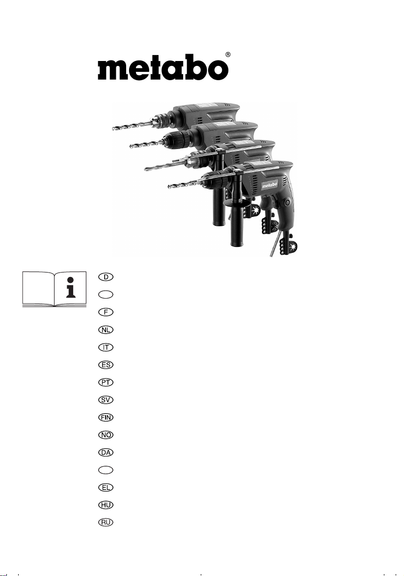
SBE 521
SBE 550
SBE 561
SB 561
BE 561
B 561
Gebrauchsanleitung ………….. Seite
ENG
Operating Instructions………..page
Mode d’emploi ………………….page
Gebruiksaanwijzing ………bladzijde
Istruzioni d’uso ………………. pagina
Instrucciones de manejo …. página
Instruções de serviço ……… página
Bruksanvisning ………………….. sida
Käyttöohje ………………………….sivu
Bruksanvisning ………………….. side
Betjeningsvejledning ………….. side
POL
Instrukcja obsługi …………….strona
Οδηγίες χρήσης…………….Σελίδα
Használati útmutató ………….. oldal
Инструкция по использованию.. стр.
170 26 8610 — 0108
5
10
15
20
25
30
35
40
45
50
55
60
65
71
76
13
P
1
P
2
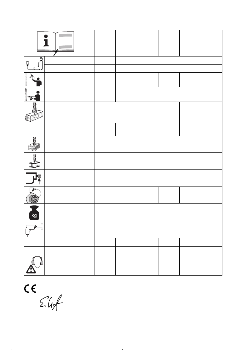
W 520 550 560
W 300 320
SBE 521
SBE 550
SBE 561
SB 561
BE 561
B 561
n
0
n
1
ø max.
s max.
/min 0-2600 0-2800 2800 0-2800 2800
/min 1600 1700
mm
(in)
/min.
bpm
47000 50000 — —
12 (1/2“) — —
ø max. mm (in) 20 (3/4“)
ø max. mm (in) 10 (3/8“)
G UNF (in)
Hmm (in)
6,35
(1/4“)
1/2“-20
mkg (lbs) 1,7 (3.7)
D
a
h, ID/Kh, ID
a
h, D/Kh, D
L
pA/KpA
L
WA/KWA
mm
(in)
m/s
m/s
2
28 / 2,0 28 / 2,0 28 / 2,0 28 / 2,0 — —
2
5 / 1,5 5 / 1,5 5 / 1,5 5 / 1,5 5 / 1,5 5 / 1,5
(1 11/16“)
dB(A) 96 / 3 96 / 3 96 / 3 96 / 3 81 / 3 81 / 3
dB(A) 107 / 3 107 / 3 107 / 3 107 / 3 92 / 3 92 / 3
43
6,35
(1/4“)
—
EN 60745
98/37/EG (
Erhard Krauß, Geschäftsführung
© 2008 Metabowerke GmbH, 72622 Nürtingen, Germany
➛
28.12.09), 2006/42/EG (29.12.09➛), 2004/108/EG
2
SBE 561, SBE 550, SBE 521, SB 561
7
1
2
3
4
SBE 561, SBE 550, SBE 521, SB 561
5
SBE 561, SBE 550, SBE 521, SB 561
6
SBE 561, SBE 550, SBE 521, BE 561
GRIP, ZU
L
R
ba
SBE 561, SBE 550, SBE 521, BE 561
ba
AUF, RELEASE
8
9
10
3 x
3
BA
6.276086.31078
C
6.00890
D
a=80
b=80
6.27106
F
6.30552
6.30553
SBE 561, SBE 550, SBE 521
ALU
ø
mm
4
6
6
8
10
12
16
20
5
6 6 6
a=100
b=100
6.12001
5
E
6.30554
a=86
b=80
6.12003
HG
SBE 561
SBE 550
6.30551
6.30550
1 2 3 4 5 6
SBE 521
1100 1400 1700 2000 2300 2600 …/min
SBE 550,
SBE 561,
1300 1600 1900 2200 2500 2800 …/min
BE 561
50 40 30 20 15 10 %
SBE 521
BE 561
6.31281
4
DEUTSCH
D
Gebrauchsanleitung
Sehr geehrter Kunde,
vielen Dank für das Vertrauen, das Sie uns beim Kauf Ihres neuen Metabo Elektrowerkzeugs
entgegengebracht haben. Jedes Metabo Elektrowerkzeug wird sorgfältig getestet und unterliegt den
strengen Qualitätskontrollen der Metabo Qualitätssicherung. Die Lebensdauer eines Elektrowerkzeugs
hängt aber in starkem Maße von Ihnen ab. Beachten Sie bitte die Informationen dieser
Gebrauchsanleitung und der beiliegenden Dokumente. Je sorgsamer Sie Ihr Metabo Elektrowerkzeug
behandeln, umso länger wird es zuverlässig seinen Dienst erfüllen.
Inhalt
1 Konformitätserklärung
2 Bestimmungsgemäße Verwendung
3 Allgemeine Sicherheitshinweise
4 Spezielle Sicherheitshinweise
5Überblick
6 Inbetriebnahme
6.1 Montage des Zusatzhandgriffs
(SBE 561, SBE 550, SBE 521, SB 561)
7 Benutzung
7.1 Verstellen des Bohrtiefenanschlags
(SBE 561, SBE 550, SBE 521, SB 561)
7.2 Ein-/Ausschalten
7.3 Drehzahl vorwählen
(SBE 561, SBE 550, SBE 521, BE 561)
7.4 Umschalten Bohren/Schlagbohren
(SBE 561, SBE 550, SBE 521, SB 561)
7.5 Drehrichtung wählen
(SBE 561, SBE 550, SBE 521, BE 561)
7.6 Werkzeugwechsel
Schnellspann-Bohrfutter Futuro Plus
7.7 Werkzeugwechsel
Zahnkranz-Bohrfutter
7.8 Bohrfutter abnehmen
8 Tipps und Tricks
9 Wartung
10 Zubehör
11 Reparatur
12 Umweltschutz
13 Technische Daten
1 Konformitätserklärung
Wir erklären in alleiniger Verantwortlichkeit, dass
dieses Produkt mit den auf Seite 2 angegebenen
Normen und Richtlinien übereinstimmt.
2 Bestimmungsgemäße
Verwendung
SBE 561, SBE 550, SBE 521, SB 561:
Die Maschine ist geeignet zum Bohren ohne
Schlag in Metall, Holz, Kunststoff und ähnlichen
Materialien und zum Schlagbohren in Beton, Stein
und ähnlichen Materialien.
BE 561, B 561:
Die Maschine ist geeignet zum Bohren ohne
Schlag in Metall, Holz, Kunststoff und ähnlichen
Materialien.
SBE 561, SBE 550, SBE 521, BE 561:
Die Maschine ist zum Gewindeschneiden und zum
Schrauben geeignet.
Für Schäden durch nicht bestimmungsgemäßen
Gebrauch haftet allein der Benutzer.
Allgemein anerkannte Unfallverhütungsvorschriften und beigelegte Sicherheitshinweise
müssen beachtet werden.
3 Allgemeine
Sicherheitshinweise
WARNUNG
Verletzungsrisikos Betriebsanleitung
lesen.
WARNUNG Lesen Sie alle Sicherheitshinweise und Anweisungen. Versäumnisse
bei der Einhaltung der Sicherheitshinweise und
Anweisungen können elektrischen Schlag, Brand
und/oder schwere Verletzungen verursachen.
Bewahren Sie alle Sicherheitshinweise und
Anweisungen für die Zukunft auf.
Lesen Sie vor der Benutzung des Elektrowerkzeugs die beiliegenden Sicherheitshinweise
und die Gebrauchsanleitung aufmerksam und
vollständig durch. Bewahren Sie alle beiliegenden
Dokumente auf und geben Sie Ihr Elektrowerkzeug
nur zusammen mit diesen Dokumenten weiter.
– Zur Verringerung eines
5
D
DEUTSCH
4 Spezielle
Sicherheitshinweise
Beachten Sie die mit diesem Symbol
gekennzeichneten Textstellen zu Ihrem
eigenen Schutz und um Schutz Ihres
Elektrowerkzeugs!
Tragen Sie Gehörschutz bei der Benutzung von
Schlagbohrmaschinen.
kann Gehörverlust bewirken.
Benutzen Sie den mit dem Gerät gelieferten
Zusatzhandgriff.
zu Verletzungen führen.
Halten Sie das Gerät an den isolierten Griffflächen, wenn Sie Arbeiten ausführen, bei denen
das Einsatzwerkzeug verborgene Stromleitungen oder das eigene Netzkabel treffen kann.
Der Kontakt mit einer spannungsführenden
Leitung kann auch metallene Geräteteile unter
Spannung setzen und zu einem elektrischen
Schlag führen.
Stecker aus der Steckdose ziehen, bevor
irgendeine Einstellung oder Wartung
vorgenommen wird.
Beachten Sie Gas-, Strom-, und Wasserleitungen!
Vermeiden Sie unbeabsichtigtes Anlaufen: stets
Schalter entriegeln, wenn der Stecker aus der
Steckdose gezogen wird, oder wenn eine
Stromunterbrechung eingetreten ist.
Nicht an das sich drehende Werkzeug fassen!
Späne und Ähnliches nur bei Stillstand der
Maschine entfernen.
Achtung beim harten Schraubfall (Einschrauben
von Schrauben mit metrischem oder Zoll-Gewinde
in Stahl)! Der Schraubenkopf kann abgerissen
werden, bzw. es können hohe Rückdrehmomente
auftreten.
Klemmt oder hakt das Einsatzwerkzeug treten
hohen Kräfte auf. Die Maschine immer kräftig
festhalten, einen sichereren Stand einnehmen
und konzentriert arbeiten.
Kleine Werkstücke befestigen. Z. B. in einen
Schraubstock einspannen.
Stäube von Materialien wie bleihaltigem Anstrich,
einigen Holzarten, Mineralien und Metall können
gesundheitsschädlich sein. Berühren oder
Einatmen der Stäube können allergische
Reaktionen und/oder Atemwegserkrankungen
des Benutzers oder in der Nähe befindlicher
Personen hervorrufen.
Bestimmte Stäube wie Eichen- oder Buchenstaub
gelten als krebserzeugend, besonders in
Verbindung mit Zusatzstoffen zur Holzbehandlung
(Chromat, Holzschutzmittel). Asbesthaltiges
Material darf nur von Fachleuten bearbeitet
6
Die Einwirkung von Lärm
Der Verlust der Kontrolle kann
werden.
— Benutzen Sie möglichst eine Staubabsaugung.
— Sorgen Sie für gute Belüftung des
Arbeitsplatzes.
— Es wird empfohlen, eine Atemschutzmaske mit
Filterklasse P2 zu tragen.
Beachten Sie in Ihrem Land gültige Vorschriften für
die zu bearbeitenden Materialien.
5Überblick
Siehe Seite 3 (bitte ausklappen).
1 Bohrfutterschlüssel
(für Zahnkranz-Bohrfutter) *
2 Zahnkranz-Bohrfutter *
3 Schnellspann-Bohrfutter Futuro Plus *
4 Bohrtiefenanschlag *
5
Zusatzhandgriff *
6 Drehrichtungsumschalter *
7 Schaltschieber Bohren/Schlagbohren *
8 Feststellknopf (Dauereinschaltung)
9 Schalterdrücker
10 Stellrad zur Drehzahlvorwahl *
* ausstattungsabhängig / modellabhängig
6 Inbetriebnahme
Vergleichen Sie vor Inbetriebnahme, ob
die auf dem Typenschild angegebene
Netzspannung und Netzfrequenz mit den Daten
Ihres Stromnetzes übereinstimmen.
SBE 561, SBE 550, SBE 521, BE 561:
Um den sicheren Halt des Bohrfutters zu
gewährleisten:
(Rechtslauf) die Sicherungsschraube im Innern
des Bohrfutters mit einem Schraubendreher
kräftig nachziehen. Achtung Linksgewinde!
(Siehe Kapitel 7.8)
6.1 Montage des Zusatzhandgriffs
Aus Sicherheitsgründen stets den
mitgelieferten Zusatzhandgriff verwenden.
Klemmring durch Linksdrehen des
Zusatzhandgriffs (5) öffnen. Zusatzhandgriff
auf Spannhals der Maschine aufschieben.
Bohrtiefenanschlag (4) einschieben.
Zusatzhandgriff je nach Anwendung im
gewünschten Winkel kräftig festziehen.
Nach dem ersten Bohren
(SBE 561, SBE 550, SBE 521, SB 561)
7 Benutzung
7.1 Verstellen des Bohrtiefenanschlags
(SBE 561, SBE 550, SBE 521, SB 561)
Zusatzhandgriff (5) lösen. Bohrtiefenanschlag (4)
auf die gewünschte Bohrtiefe einstellen und
Zusatzhandgriff wieder festziehen.
7.2 Ein-/Ausschalten
Zum Einschalten der Maschine Schalterdrücker (9)
drücken.
SBE 561, SBE 550, SBE 521, BE 561: Die Drehzahl
kann am Schalterdrücker durch Eindrücken
verändert werden.
Für Dauereinschaltung kann der Schalterdrücker
mit dem Feststellknopf (8) arretiert werden. Zum
Ausschalten Schalterdrücker erneut drücken.
Bei Dauereinschaltung läuft die Maschine
weiter, wenn sie aus der Hand gerissen
wird. Daher die Maschine immer mit beiden
Händen an den vorgesehenen Handgriffen
festhalten, einen sicheren Stand einnehmen
und konzentriert arbeiten.
7.3 Drehzahl vorwählen
(SBE 561, SBE 550, SBE 521, BE 561)
Am Stellrad (10) die maximale Drehzahl vorwählen.
Empfohlene Drehzahlen zum Bohren siehe Seite 4.
7.4 Umschalten Bohren/Schlagbohren
(SBE 561, SBE 550, SBE 521, SB 561)
Die gewünschte Betriebsart durch Verschieben
des Schaltschiebers (7) wählen.
Bohren
Schlagbohren
Im Schlagbohrbetrieb mit hoher Drehzahl arbeiten.
Schlagbohren und Bohren nur bei
Rechtslauf.
7.5 Drehrichtung wählen
(SBE 561, SBE 550, SBE 521, BE 561)
Drehrichtungsumschalter (6) nur bei
Stillstand des Motors betätigen.
Drehrichtung wählen:
R=Rechtslauf
L = Linkslauf
dabei
sicher
D
DEUTSCH
Das Bohrfutter muss kräftig auf die
Spindel aufgeschraubt und die
Sicherungsschraube im Innern des Bohrfutters
mit einem Schraubendreher kräftig
festgezogen sein. (Achtung Linksgewinde!)
Im Linkslauf (z.B. beim Schrauben) könnte es
sich sonst lösen.
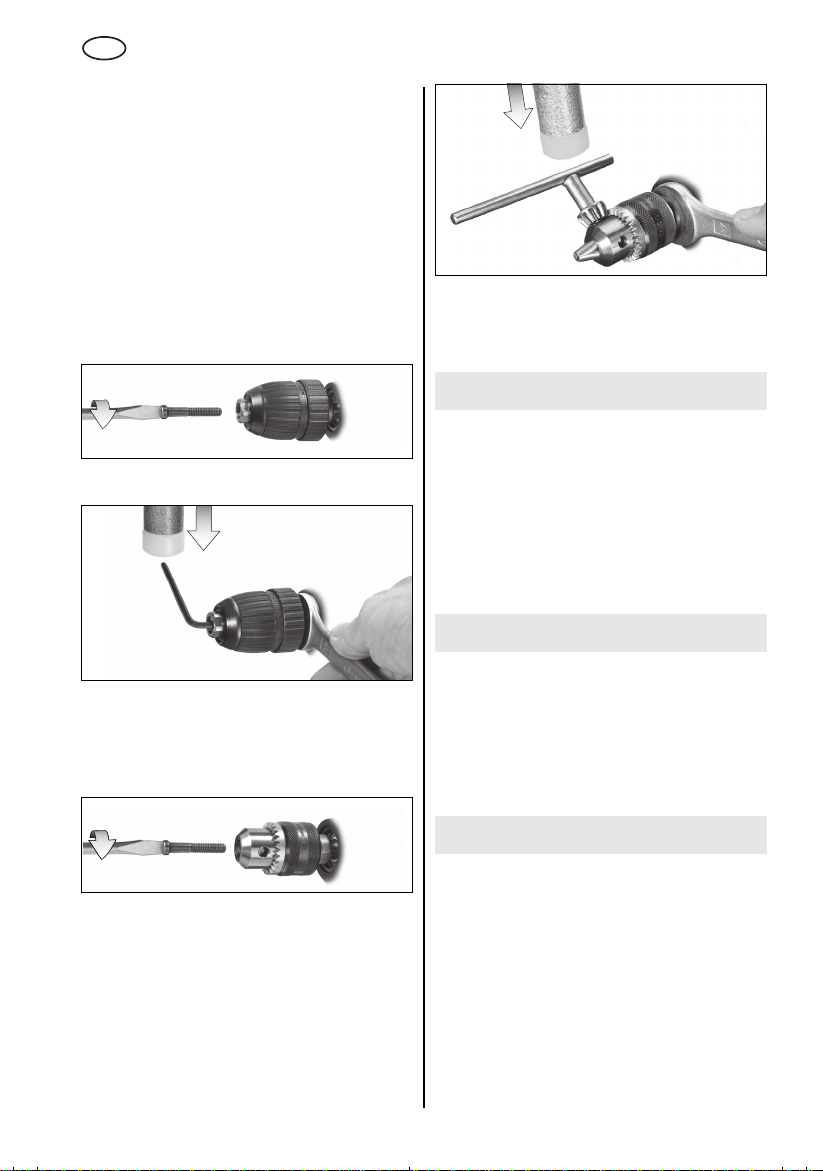
7.6 Werkzeugwechsel
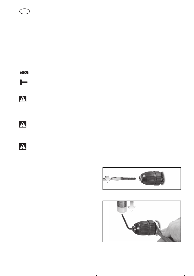
Schnellspann-Bohrfutter Futuro Plus (3)
Maschinen mit der Bezeichnung SB…:
Siehe Abbildungen, Seite 3.
Werkzeug einsetzen. Haltering (a) festhalten und
mit der anderen Hand die Hülse (b) in Richtung
«GRIP, ZU» drehen, bis der spürbare mechanische
Widerstand überwunden ist.
Achtung! Werkzeug ist jetzt noch nicht
gespannt!
muss es «klicken»
möglich ist gespannt.
Bei weichem Werkzeugschaft muss eventuell nach
kurzer Bohrzeit nachgespannt werden.
Bohrfutter öffnen:
Haltering (a) festhalten und mit der anderen Hand
Hülse (b) in Richtung «AUF, RELEASE» drehen.
Hinweis:
eventuell hörbare Ratschen (funktionsbedingt)
wird durch Gegendrehen der Hülse ausgeschaltet.
Bei sehr fest geschlossenem Bohrfutter:
Netzstecker ziehen. Das Bohrfutter mit einem
Gabelschlüssel am Bohrfutterkopf festhalten und
Hülse (b) kräftig in Richtung «AUF, RELEASE»
drehen.
Maschinen mit der Bezeichnung B…:
Siehe Abbildungen, Seite 3.
Werkzeug einsetzen. Haltering (a) festhalten und
mit der anderen Hand die Hülse (b) in Richtung
«GRIP, ZU» drehen, bis kein Weiterdrehen mehr
möglich ist.
Bei weichem Werkzeugschaft muss eventuell nach
kurzer Bohrzeit nachgespannt werden.
Bohrfutter öffnen:
Haltering (a) festhalten und mit der anderen Hand
Hülse (b) in Richtung «AUF, RELEASE» drehen.
Bei sehr fest geschlossenem Bohrfutter:
Netzstecker ziehen. Das Bohrfutter mit einem
Gabelschlüssel am Bohrfutterkopf festhalten und
Hülse (b) kräftig in Richtung «AUF, RELEASE»
drehen.
So lange kräftig weiterdrehen (
), bis kein Weiterdrehen mehr
erst jetzt
Das nach dem Öffnen des Bohrfutters
ist das Werkzeug
7
D
DEUTSCH
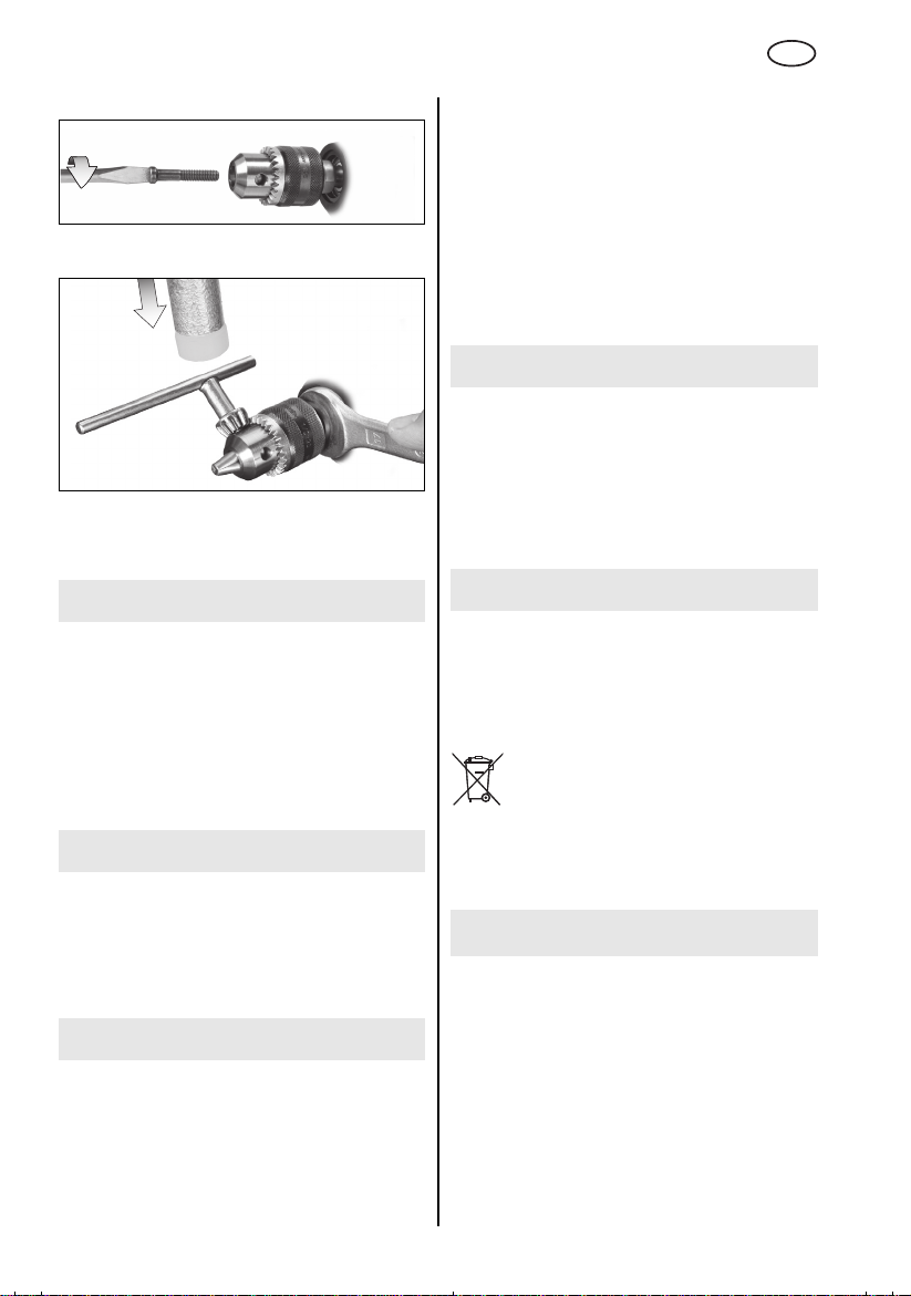
7.7 Werkzeugwechsel
Zahnkranz-Bohrfutter (2)
Siehe Abbildungen, Seite 3.
Werkzeug einspannen:
Werkzeug einsetzen und mit Bohrfutterschlüssel
(1) gleichmäßig in allen 3 Bohrungen festspannen.
Werkzeug entnehmen:
Zahnkranz-Bohrfutter (2) mit Bohrfutterschlüssel
(1) öffnen und Werkzeug entnehmen.
7.8 Bohrfutter abnehmen
Schnellspann-Bohrfutter Futuro Plus
Sicherungsschraube herausdrehen — falls
vorhanden. Achtung Linksgewinde!
Bohrspindel mit einem Gabelschlüssel festhalten.
Bohrfutter durch leichten Schlag mit einem
Gummihammer auf einen eingespannten
Sechskantschlüssel lösen und abschrauben.
Zahnkranzbohrfutter
Bohrspindel mit einem Gabelschlüssel festhalten.
Bohrfutter durch leichten Schlag mit einem
Gummihammer auf den eingesteckten
Bohrfutterschlüssel lösen und abschrauben.
8 Tipps und Tricks
Bei tiefen Bohrungen den Bohrer von Zeit zu Zeit
aus der Bohrung ziehen, um das Bohrmehl oder
Späne zu entfernen.
SBE 561, SBE 550, SBE 521, BE 561: Zum
Schrauben kann das Bohrfutter abgeschraubt
werden. Schrauber-Bit direkt in den
Innensechskant der Spindel einsetzen.
Bei angebrachter Bit-Spannbuchse
Best.-Nr. 6.31281)
gehalten.
wird der Schrauber-Bit
(als Zubehör:
9 Wartung
Schnellspannbohrfutter reinigen:
Nach längerem Gebrauch das Bohrfutter mit der
Öffnung senkrecht nach unten halten und
mehrmals ganz öffnen und schließen. Der
angesammelte Staub fällt aus der Öffnung. Die
regelmäßige Anwendung von Reinigungsspray an
den Spannbacken und Spannbackenöffnungen
wird empfohlen.
f
10 Zubehör
Sicherungsschraube herausdrehen — falls
vorhanden. Achtung Linksgewinde!
8
Verwenden Sie nur original Metabo Zubehör.
Wenn Sie Zubehör benötigen, wenden Sie sich
bitte an Ihren Händler.
Zur Auswahl des richtigen Zubehörs teilen Sie
dem Händler bitte den genauen Typ Ihres
Elektrowerkzeugs mit.
Siehe Seite 4.
A Winkelbohr- und Schraubvorsatz
B Biegewelle
CBohrständer
D Maschinenschraubstock
E Stahldraht-Pinselbürste
DEUTSCH
D
F Stahldraht-Topfbürste
G Stahldraht-Rundbürste
H Bit-Spannbuchse
Zubehör-Komplettprogramm siehe
www.metabo.com oder Hauptkatalog.
11 Reparatur
Reparaturen an Elektrowerkzeugen dürfen nur
durch eine Elektrofachkraft ausgeführt werden!
Reparaturbedürftige Metabo Elektrowerkzeuge
können an die auf der Ersatzteilliste angegebenen
Adressen eingesandt werden.
Bitte beschreiben Sie bei der Einsendung zur
Reparatur den festgestellten Fehler.
12 Umweltschutz
Metaboverpackungen sind 100% recyclingfähig.
Ausgediente Elektrowerkzeuge und Zubehör
enthalten große Mengen wertvoller Roh- und
Kunststoffe, die ebenfalls einem Recyclingprozess
zugeführt werden können.
Diese Gebrauchsanleitung ist auf chlorfrei
gebleichtem Papier gedruckt.
Nur für EU-Länder: Werfen Sie
Elektrowerkzeuge nicht in den Hausmüll!
Gemäß Europäischer Richtlinie
2002/96/EG über Elektro- und ElektronikAltgeräte und Umsetzung in nationales Recht
müssen verbrauchte Elektrowerkzeuge getrennt
gesammelt und einer umweltgerechten
Wiederverwertung zugeführt werden.
13 Technische Daten
Erläuterungen zu den Angaben auf Seite 2.
Änderungen im Sinne des technischen Fortschritts
vorbehalten.
= Nennaufnahmeleistung
P
1
P
= Abgabeleistung
2
n
= Leerlaufdrehzahl
0
n
= Drehzahl bei Nennlast
1
ø max = maximaler Bohrdurchmesser
s max = maximale Schlagzahl
G = Bohrspindelgewinde
H = Bohrspindel mit Innensechskant
m = Gewicht ohne Netzkabel
D = Spannhalsdurchmesser
Schwingungsgesamtwert (Vektorsumme dreier
Richtungen) ermittelt entsprechend EN 60745:
a
= Schwingungsemissionswert
h, ID
a
h, D
K
h,ID,Kh,D
(Schlagbohren in Beton)
= Schwingungsemissionswert
(Bohren in Metall)
= Unsicherheit (Schwingung)
Der in diesen Anweisungen angegebene
Schwingungspegel ist entsprechend einem in
EN 60745 genormten Messverfahren gemessen
worden und kann für den Vergleich von
Elektrowerkzeugen miteinander verwendet
werden. Er eignet sich auch für eine vorläufige
Einschätzung der Schwingungsbelastung.
Der angegebene Schwingungspegel repräsentiert
die hauptsächlichen Anwendungen des
Elektrowerkzeugs. Wenn allerdings das
Elektrowerkzeug für andere Anwendungen,
mit abweichenden Einsatzwerkzeugen oder
ungenügender Wartung eingesetzt wird, kann der
Schwingungspegel abweichen. Dies kann die
Schwingungsbelastung über den gesamten
Arbeitszeitraum deutlich erhöhen.
Für eine genaue Abschätzung der
Schwingungsbelastung sollten auch die Zeiten
berücksichtigt werden, in denen das Gerät
abgeschaltet ist oder zwar läuft, aber nicht
tatsächlich im Einsatz ist. Dies kann die
Schwingungsbelastung über den gesamten
Arbeitszeitraum deutlich reduzieren.
Legen Sie zusätzliche Sicherheitsmaßnahmen
zum Schutz des Bedieners vor der Wirkung von
Schwingungen fest wie zum Beispiel: Wartung von
Elektrowerkzeug und Einsatzwerkzeugen,
Warmhalten der Hände, Organisation der
Arbeitsabläufe.
Typische A-bewertete Schallpegel:
L
= Schalldruckpegel
pA
L
= Schallleistungspegel
WA
K
, KWA= Unsicherheit (Schallpegel)
pA
Beim Arbeiten kann der Geräuschpegel 85 dB(A)
überschreiten.
Gehörschutz tragen!
Messwerte ermittelt gemäß EN 60745.
Die angegebenen technischen Daten sind
toleranzbehaftet (entsprechend den jeweils
gültigen Standards).
9
ENG
ENGLISH
Operating Instructions
Dear Customer,
Thank you for the trust you have placed in us by buying a Metabo power tool. Each Metabo power tool
is carefully tested and subject to strict quality controls by Metabo’s quality assurance. Nevertheless, the
service life of a power tool depends to a great extent on you. Please observe the information contained
in these instructions and the enclosed documentation. The more carefully you treat your Metabo power
tool, the longer it will provide dependable service.
Contents
1 Declaration of Conformity
2 Specified Conditions of Use
3 General Safety Instructions
4 Special Safety Instructions
5Overview
6 Initial Operation
6.1 Attaching the Additional Handle
(SBE 561, SBE 550, SBE 521,
SB 561)
7Use
7.1 Adjusting the Depth Stop (SBE 561,
SBE 550, SBE 521, SB 561)
7.2 Switching On and Off
7.3 Speed Preselection (SBE 561,
SBE 550, SBE 521, BE 561)
7.4 Switching Between Normal Drilling/
Impact Drilling
SBE 521, SB 561)
7.5 Selecting the Direction of Rotation
(SBE 561, SBE 550, SBE 521, BE 561)
7.6 Tool Change With Futuro Plus Keyless
Chuck (3)
7.7 Tool Change With Geared Chuck (2)
7.8 Removing the Chuck
8 Tips and Tricks
9 Maintenance
10 Accessories
11 Repairs
12 Environmental Protection
13 Technical Specifications
(SBE 561, SBE 550,
1 Conformity Declaration
We, being solely responsible, hereby declare that
this product conforms to the standards and directives specified on page 2.
2 Specified Use
SBE 561, SBE 550, SBE 521, SB 561:
The machine is suitable for non-impact drilling in
metal, wood, plastic and similar materials and
impact drilling in concrete, stone and similar materials.
BE 561, B 561:
The machine is suitable for non-impact drilling in
metal, wood, plastic and similar materials.
SBE 561, SBE 550, SBE 521, BE 561:
The machine is suitable for thread cutting and
screwdriving.
The user bears sole responsibility for damage
caused by improper use.
Generally accepted accident prevention regulations and the enclosed safety information must be
observed.
3 General Safety Instructions
WARNING
instructions will reduce the risk
of injury.
WARNING Read all safety warnings and
instructions. Failure to follow all safety
warnings and instructions may result in electric
shock, fire and/or serious injury.
Keep all safety instructions and information for
future reference.
Before using the power tool, carefully read through
and familiarise yourself with all the enclosed safety
information and the Operating Instructions. Keep
all enclosed documentation for future reference,
and pass on your power tool only together with this
documentation.
– Reading the operating
4 Special Safety Instructions
For your own protection and the protection of your power tool, observe the
passages marked by this symbol!
10
Always wear hearing protection when using
hammer drills.
of hearing.
Exposure to noise can cause loss

ENGLISH
ENG
Use the additional handle supplied with the
tool.
Loss of control can lead to injuries.
Hold the power tool by insulated gripping
surfaces when performing an operation where
the cutting accessory may contact hidden
wiring or its own cord.
contacting a «live» wire may make exposed
metal parts of the power tool «live» and shock the
operator.
Pull the plug out of the plug socket before any
adjustments or servicing are performed.
Beware of gas/water pipes and electric cables!
Avoid inadvertent starts by always unlocking the
switch when the plug is removed from the mains
socket or in case of a power cut.
Keep hands away from the rotating tool!
Remove chips and similar material only with the
machine at standstill.
Caution must be exercised when driving screws
into hard materials (driving screws with metric or
imperial threads into steel)! The screw head may
break or a high reverse torque may build up.
The machine produces powerful forces when
seizing or catching the workpiece. Always hold the
machine firmly, adopt a steady stance and focus on
your work.
Secure small workpieces. For example, clamp in a
vice.
Dust from material such as paint containing lead,
some wood species, minerals and metal may be
harmful. Contact with or inhalation of the dust may
cause allergic reactions and/or respiratory
diseases to the operator or bystanders.
Certain kinds of dust are classified as carcinogenic
such as oak and beech dust especially in conjunction with additives for wood conditioning (chromate,
wood preservative). Material containing asbestos
must only be treated by specialists.
— Where the use of a dust extraction device is
possible it shall be used.
— The work place must be well ventilated.
— The use of a dust mask of filter class P2 is
recommended.
Follow national requirements for the materials you
want to work with.
Cutting accessory
5Overview
See page 3 (please unfold).
1 Chuck key (for geared chuck) *
2 Geared chuck *
3 Futuro Plus keyless chuck *
4Depth stop *
5
Additional handle *
6 Direction switch *
7 Sliding switch for normal drilling/impact
drilling *
8 Lock button (continuous operation)
9Trigger
10 Speed preselection wheel *
* depending on the features / model
6 Commissioning
Before plugging in, check to see that the
rated mains voltage and mains frequency,
as stated on the rating label, match with your
power supply.
SBE 561, SBE 550, SBE 521, BE 561:
Make sure the chuck clamps securely:
After drilling for the first time (clockwise), firmly
tighten the safety screw inside the chuck using
a screwdriver. Caution: left-handed thread!
(see Section 7.8)
6.1 Attaching the Additional Handle
(SBE 561, SBE 550, SBE 521, SB 561)
For safety reasons, always use the
additional handle supplied.
Open the clamping ring by turning the additional
handle (5) anticlockwise. Push the additional
handle onto the collar of the machine. Insert the
depth stop (4). Securely tighten the additional
handle at the angle required for the application.
7Use
7.1 Adjusting the Depth Stop
(SBE 561, SBE 550, SBE 521, SB 561)
Loosen the additional handle (5). Set depth stop (4)
to the desired drilling depth and retighten additional handle.
7.2 Switching On and Off
To start the machine, press the trigger switch (9).
SBE 561, SBE 550, SBE 521, BE 561: Press in the
trigger switch to change the speed.
For continuous operation the trigger switch can be
locked using the lock button (8). To stop the
machine, press the trigger switch again.
In continuous operation, the machine
continues running if it is forced out of your
hands. Therefore, always hold the machine
with both hands using the handles provided,
stand in a safe position and concentrate.
11
ENG
ENGLISH
7.3 Speed Preselection
(SBE 561, SBE 550, SBE 521, BE 561)
Select the (10) maximum speed using the preselection wheel. See page 4 for recommended
drilling speeds.
7.4 Switching Between Normal Drilling/
Impact Drilling
(SBE 561, SBE 550, SBE 521, SB 561)
Select the desired operating mode by pushing the
sliding switch (7).
Drilling
Impact drilling
Work with high speed settings when impact drilling.
Impact drilling and normal drilling only in a
clockwise direction.
7.5 Selecting the Direction of Rotation
(SBE 561, SBE 550, SBE 521, BE 561)
Do not activate the direction switch (6)
unless the motor has completely stopped.
Select direction of rotation:
R=Clockwise
L = Anticlockwise
Screw the chuck firmly to the spindle and
tighten the safety screw inside the chuck
using a screwdriver. (Caution: left-handed
thread!)
Otherwise it may come loose during anticlockwise operation (e.g. when screwdriving).
If the chuck is very securely tightened:
Hold the drill chuck using an open-end spanner at
the flats on its head, and turn the sleeve (b) vigourously in the direction of «AUF, RELEASE».
Machines with the designation B…:
See illustrations on page 3.
Insert the tool. Hold the retaining ring (a) firmly and
turn the collet (b) towards «GRIP, ZU» with the other
hand until it will not turn any further.
With a soft tool shank, retightening may be required
after a short drilling period.
Open the chuck:
Hold the retaining ring (a) firmly and turn the collet
(b) towards «AUF, RELEASE» with the other hand.
If the chuck is very securely tightened:
Hold the drill chuck using an open-end spanner at
the flats on its head, and turn the sleeve (b) vigourously in the direction of «AUF, RELEASE».
7.7 Tool Change With
Geared Chuck (2)
See illustrations on page 3.
Clamping tools:
Insert the tool and clamp evenly in all 3 holes using
the chuck key (1).
Removing tools:
Open the geared chuck (2) using the chuck key (1)
and remove the tool.
7.8 Removing the Chuck
Futuro Plus keyless chuck
Unplug.
Unplug.
7.6 Tool Change With
Futuro Plus Keyless Chuck (3)
Machines with the designation SB…:
See illustrations on page 3.
Insert the tool. Hold the retaining ring (a) firmly and
turn the collet (b) towards «GRIP, ZU» with the other
hand until the mechanical resistance which can be
felt is overcome.
Caution! The tool is not yet clamped!
turning the sleeve (
until it cannot be turned any further the tool
securely
With a soft tool shank, retightening may be required
after a short drilling period.
Open the chuck:
Hold the retaining ring (a) firmly and turn the collet
(b) towards «AUF, RELEASE» with the other hand.
Note:
The grating sound which may be heard after
opening the drill chuck is functional and is stopped
by turning the sleeve in the opposite direction.
it must «click» when turning
clamped.
Keep
only now
is
12
Unscrew the safety screw — if available. Caution:
left-handed thread!
)
Hold the drill spindle securely using an open-end
wrench. Clamp an Allen key in the chuck and strike
lightly with a rubber hammer to loosen, then
unscrew.
ENGLISH
ENG
Geared chuck
Unscrew the safety screw — if available. Caution:
left-handed thread!
Hold the drill spindle securely using an open-end
wrench. Insert the key in the chuck and strike lightly
with a rubber hammer to loosen, then unscrew.
8 Tips and Tricks
In the case of deep bores, pull the drill bit out of the
bore from time to time in order to remove the drill
dust or swarf.
SBE 561, SBE 550, SBE 521, BE 561: The chuck
can be removed to insert a screwdriver bit. Insert
the bit directly in the hexagon socket on the
spindle.
The screwdriver bit is retained if a bit clamping
bush
(as an accessory: order no. 6.31281)
is fitted.
9 Maintenance
Keyless chuck cleaning:
After prolonged use hold the chuck vertically, with
the opening facing down, and fully open and close
it several times. The dust collected falls from the
opening. Regular use of cleaning spray on the jaws
and jaw openings is recommended.
f
10 Accessories
Use only genuine Metabo accessories.
If you need any accessories, check with your
dealer.
For dealers to select the correct accessory, they
need to know the exact model designation of your
power tool.
See page 4.
A Angle attachment
B Flexible drive shaft
C Drill stand
D Machine vice
E Steel wire end brush
F Steel wire cup brush
G Steel wire wheel
H Bit clamping bush
For complete range of accessories, see
www.metabo.com or the main catalogue.
11 Repairs
Repairs to electrical tools must be carried out by
qualified electricians ONLY!
Any Metabo power tool in need of repair can be
sent to one of the addresses listed in the spare
parts list.
Please enclose a description of the fault with the
power tool.
12 Environmental Protection
Metabo’s packaging can be 100% recycled.
Scrap power tools and accessories contain large
amounts of valuable resources and plastics that
can be recycled.
These instructions are printed on chlorine-free
bleached paper.
Only for EU countries: Never dispose of
power tools in your household waste! In
accordance with European Guideline
2002/96/EC on used electronic and
electric equipment and its implementation in
national legal systems, used power tools must be
collected separately and handed in for
environmentally compatible recycling.
13 Technical Specifications
Explanatory notes on the specifications on page 2.
Changes due to technological progress reserved.
P
= Nominal power input
1
P2 = Power output
n
= No load speed
0
n
= Speed at rated load
1
ø max = Max. solid drill diameter
s max = Max. impact rate
G = Drill spindle thread
H = Drill spindle with hexagon socket
m = Weight without mains cable
D = Collar diameter
13

ENG
ENGLISH
Vibration total value (vector sum of three
directions) determined in accordance with
EN 60745:
a
= Vibration emission value
h, ID
a
h, D
K
h,ID,Kh,D
The vibration emission level given in this information sheet has been measured in accordance with
a standardised test given in EN 60745 and may be
used to compare one tool with another. It may be
used for a preliminary assessment of exposure.
(impact drilling into concrete)
= Vibration emission value
(drilling into metal)
= Unsafe (vibration)
The declared vibration emission level represents
the main applications of the tool. However if the tool
is used for different applications, with different
accessories or poorly maintained, the vibration
emission may differ. This may significantly increase
the exposure level over the total working period.
An estimation of the level of exposure to vibration
should also take into account the times when the
tool is switched off or when it is running but not
actually doing the job. This may significantly reduce
the exposure level over the total working period.
Identify additional safety measures to protect the
operator from the effects of vibration such as:
maintain the tool and the accessories, keep the
hands warm, organisation of work patterns.
Typical A-effective perceived sound levels:
L
= Sound pressure level
pA
L
= Acoustic power level
WA
K
, KWA= Unsafe (noise level)
pA
During operation the noise level can exceed
85 dB(A).
Wear ear protectors!
Measured values determined in conformity with
EN 60745.
The technical specifications quoted are subject to
tolerances (in compliance with the relevant valid
standards).
14
FRANÇAIS
F
Mode d’emploi
Cher client,
merci de la confiance que vous nous avez témoignée en achetant un outil électrique Metabo. Tous les
outils électriques Metabo sont testés avec soin et font l’objet de contrôles qualité très stricts effectués
par le Service Qualité Metabo. Mais c’est vous qui avez la plus grande influence sur la durée de vie de
votre outil électrique. Veuillez respecter les informations contenues dans ces instructions d’utilisation et
dans les documents ci-joints. En prenant grand soin de votre outil électrique Metabo, vous en augmenterez la durée de vie et en garantirez le bon fonctionnement.
Sommaire
1 Déclaration de conformité
2 Utilisation conforme à la destination
3 Consignes générales de sécurité
4 Consignes de sécurité particulières
5Vue d’ensemble
6 Mise en service
6.1 Montage de la poignée supplémentaire (SBE 561, SBE 550, SBE 521,
SB 561)
7 Utilisation
7.1 Réglage de la butée de profondeur de
perçage (SBE 561, SBE 550,
SBE 521, SB 561)
7.2 Marche/arrêt
7.3 Présélection de la vitesse (SBE 561,
SBE 550, SBE 521, BE 561)
7.4
Sélection perçage avec/sans percussion
(SBE 561, SBE 550, SBE 521, SB 561)
7.5 Sélection du sens de rotation
(SBE 561, SBE 550, SBE 521, BE 561)
7.6 Changement d’accessoire avec le
mandrin autoserrant Futuro Plus (3)
7.7 Changement d’accessoire avec le
mandrin à clé (2)
7.8 Dépose du mandrin
8 Conseils et astuces
9 Maintenance
10 Accessoires
11 Réparations
12 Protection de l’environnement
13 Caractéristiques techniques
1 Déclaration de conformité
Nous déclarons sous notre propre responsabilité
que ce produit est conforme aux normes et directives indiquées page 2.
2 Utilisation conforme à la
destination
SBE 561, SBE 550, SBE 521, SB 561 :
Cette machine convient pour le perçage sans
percussion sur métal, bois, matières plastiques et
assimilées, ainsi que pour le perçage avec percussion sur béton, pierre et matériaux similaires.
BE 561, B 561 :
Cette machine convient pour le perçage sans
percussion sur métal, bois, matières plastiques et
assimilées.
SBE 561, SBE 550, SBE 521, BE 561 :
Cette machine convient pour les travaux de taraudage et de vissage.
L’utilisateur sera entièrement responsable de tous
dommages résultant d’une utilisation non
conforme à la destination de la machine.
Il est impératif de respecter les consignes
générales de protection contre les accidents ainsi
que les consignes de sécurité ci-jointes.
3 Consignes générales de
sécurité
AVERTISSEMENT
d’utilisation afin d’éviter tout risque de
blessure.
AVERTISSEMENT Lire toutes les
consignes de sécurité et instructions.
Le non-respect des consignes de sécurité et des
instructions peut être à l’origine d’un choc
électrique, d’un incendie et/ou de blessures
graves.
Conserver toutes les consignes de sécurité et
instructions.
Avant d’utiliser l’outil électrique, lire attentivement
et entièrement les instructions de sécurité ainsi
que le mode d’emploi ci-joints. Conserver les
documents ci-joints et veiller à les remettre
obligatoirement avec l’appareil à tout utilisateur
concerné.
– Lire la notice
15
Loading…
Наши гарантии:
Качественные запчасти. Обязательность поставки. Надежность.
Ваш Seltop.ru
Вся информация на сайте размещена в целях предоставления возможности покупателю ознакомиться с товаром перед его приобретением, и не является публичной офертой (статья 437 ГК РФ). Информация о товарах на сайте может обновляться в течение нескольких часов. О наличии и стоимости товара уточняйте у менеджера по телефону 8 (495) 221-07-05 с 6:00 до 18:00.
Качество:
Мы не торгуем поддельными запасными частями. Преимущество оригинальных запасных частей обусловлено тем, что они изготовлены на тех же заводах, что и запчасти которые ставятся при производстве. Мы даем 100% гарантию что вернем деньги если запчасть больше не поставляется или снята с производства.
Интернет-магазин
ООО «Селтоп»
Селтоп-запчасти
Юридический адрес:
129626,
Россия,
г. Москва,
улица Маломосковская, д.22, стр.12, эт.1, пом. 1, ком 1,3, часть ком.2,
Адреса всех пунктов самовывоза здесь >>
© 2006 — 2025 SelTop.ru
Электронная ударная дрель. Прочная конструкция разъемного корпуса. Долговечный мотор. Вариоспиид (V)-Полноволновая электроника. Реверс. Вращающий момент 5 Нм.
| Характеристики товара | |
| вес | 1,7 кг |
| диаметр сверления в бетоне | 12 мм |
| диаметр сверления в дереве | 20 мм |
| диаметр сверления в стали | 10 мм |
| количество ударов в минуту 1 скорость | 0-50000 уд/мин |
| мощность | 560 Ватт |
| патрон | быстрозажимной 13 мм |
| число оборотов 1 скорость | 0-2800 об/мин |
Написать отзыв
Ваше Имя:
Ваш отзыв:
Внимание: HTML не поддерживается! Используйте обычный текст.
Оценка: Плохо
Хорошо
Введите код с картинки:

www.metabo.com
de Originalbetriebsanleitung 5
en Original instructions 9
fr Notice originale 12
nl Oorspronkelijke gebruiksaanwijzing 16
it Istruzioni originali 20
es Manual original 24
pt Manual original 28
sv Bruksanvisning i original 32
fi Alkuperäiset ohjeet 35
no Original bruksanvisning 38
da Original brugsanvisning 41
pl Instrukcja oryginalna 44
el Πρωτότυπο οδηγιών χρήσης 48
hu Eredeti üzemeltetési útmutató 52
ru Оригинальное руководство по
эксплуатации 56
SBE 521
SBE 550
SBE 561
SB 561
BE 561
B 561