
LtAP mini LTE series user manual for models:
LtAP mini LTE kit (RB912R-2nD-LTm&R11e-LTE)
LtAP mini LTE kit-US (RB912R-2nD-LTm&R11e-LTE-US)
LtAP mini 4G kit (RB912R-2nD-LTm&R11e-4G)
The LtAP mini LTE kit is a wireless access point with two SIM card slots. The LtAP mini LTE, 4G kit comes with a factory-installed card.
Safety Warnings
Before you work on any equipment, be aware of the hazards involved with electrical circuitry, and be familiar with standard practices for preventing accidents.
Ultimate disposal of this product should be handled according to all national laws and regulations.
All installation methods for mounting an access point on any wall surface is subject to the acceptance of local jurisdiction.
The Installation of the equipment must comply with local and national electrical codes.
This product is intended to be mounted outdoors on a pole but can also be installed indoors. Please read the mounting instructions carefully before beginning installation. Failure to use the correct hardware and configuration or to follow the correct procedures could result in a hazardous situation for people and damage to the system.
Use only the power supply and accessories approved by the manufacturer, and which can be found in the original packaging of this product.
Read the installation instructions before connecting the system to the power source.
We cannot guarantee that no accidents or damage will occur due to the improper use of the device. Please use this product with care and operate at your own risk!
In the case of device failure, please disconnect it from power. The fastest way to do so is by unplugging the power plug from the power outlet.
It is the customer’s responsibility to follow local country regulations, including operation within legal frequency channels, output power, cabling requirements, and Dynamic Frequency Selection (DFS) requirements. All Mikrotik radio devices must be professionally installed.
The equipment is not tested for Outdoor use by UL.
Exposure to Radio Frequency Radiation: This MikroTik equipment complies with the FCC, IC, and European Union radiation exposure limits set forth for an uncontrolled environment. This MikroTik device should be installed and operated no closer than 20 centimeters from your body, occupational user, or the general public.
Connecting
- Connect your Internet cable to the Ethernet port (this is optional if using LTE as the primary connection);
- Install your modem using miniPCIe slot (optional);
- Insert the SIM card into the SIM slot;
- Connect the GPS antenna (see «GPS usage», optional);
- Choose your powering solution (see «Powering»);
- Navigate to the network connections section on your computer and locate the wireless network named «MikroTik-….«. Proceed to connect to it;
-
Configuration should be made via a wireless network using a web browser or mobile application. Alternatively, you can use the WinBox configuration tool https://mt.lv/winbox;
- Open the http://192.168.88.1 in your web browser;
- User name: admin, and there is no password (or, for some models, check user and wireless passwords on the sticker);
- Click the «Check for updates» button and update RouterOS to the latest version. The device requires an active internet connection;
- For a manual update of the device, visit the products page at https://mikrotik.com/products to find your product. The required packages are accessible under the «Support&Downloads» menu;
- Upload downloaded packages to the «WinBox Files» menu and reboot the device;
- By upgrading your RouterOS software to the latest version, you can ensure optimal performance, stability, and security updates;
- In the «QuickSet» menu set up the following: Choose your country, to apply country regulation settings;
- Set up your wireless network password in the left field;
- Set up your router password in the bottom field.
Mounting
- It is possible to attach the device to a wall, using the provided screw holes on the sides of the unit. The device should be mounted in a way that the cable openings are pointing downward as shown in the picture.
- The ports are protected with a small door, that is held in place with one screw. Use the Philips PH2 screwdriver to access the ports.
- The door has cut-out places for all available ports, but please only break out the openings that you will use. The device can be used both indoors and outdoors. The IP rating scale for this device is IP54.
- The device enclosure has places where you can drill openings for external LTE and GPS antennas. Use a drill to make holes that are appropriate for the antenna cable used.
When mounting outdoors, please ensure that any cable openings are directed downwards. Use a PoE injector and proper grounding. Recommended using Cat6 cable.
Warning! This equipment should be installed and operated with a minimum distance of 20 cm between the device and your body. Operation of this equipment in the residential environment could cause radio interference.
Mounting and configuration of this device should be done by a qualified person.
Powering
- Direct-input power jack (5.5 mm outside and 2 mm inside, female, pin-positive plug) accepts 8-30 V DC.
- micro USB port accepts 5 V powering.
- Ethernet port accepts passive and 802.3af/at Power over Ethernet 8-57 V DC (compensate for the loss on cable, so more than 12 V recommended).
The power consumption under maximum load with attachments can reach 9 W.
Connecting to a PoE Adapter:
- Connect the Ethernet cable from the device to the PoE+DATA port of the PoE adapter.
- Connect an Ethernet cable from your local network (LAN) to the PoE adapter.
- Connect the power cord to the adapter, and then plug the power cord into a power outlet.
Extension slots and ports
- Built-in 2 GHz wireless access point module, AP/station/bridge/p2p modes are supported. Onboard PIF antennas built-in. Antenna gain1.5 dBi.
- miniPCIe slot and two SIM slots (can’t be used without a modem installed, can’t be used both at the same time) to be used with a 3G/4G/LTE modem. Onboard antennas are available, but openings for external antennas are provided on the case.
- Built-in GPS module — uFL connector provided for an external antenna. To enable, set the port to serial0 (this disables the DB9 port on the unit). Supports (GPS, GLONASS, BeiDou, Galileo).
- One 10/100 Ethernet port, supporting automatic cross/straight cable correction (Auto MDI/X). Either straight or crossover cable can be used for connecting to other network devices. The Ethernet port accepts 12-57 V DC powering from a passive PoE injector.
- One DB9 RS232 serial port for serial console access. Configured as 115200 bit/s, 8 data bits, 1 stop bit, no parity. Can’t be used if built-in GPS is enabled on serial0.
- One micro USB 2.0 port for powering only.
Configuration
RouterOS includes many configuration options in addition to what is described in this document. We suggest starting here to get yourself accustomed to the possibilities: https://mt.lv/help. In case IP connection is not available, the Winbox tool (https://mt.lv/winbox) can be used to connect to the MAC address of the device from the LAN side (all access is blocked from the internet port by default).
For recovery purposes, it is possible to boot the device from the network, see section Buttons and jumpers.
miniPCIe slot usage
The device is equipped with a miniPCIe slot and a factory-installed LTE modem. Two SIM slots are provided for use together with a miniPCIe modem. The SIM slot is not used separately.
In this case, an internal antenna is connected to the modem. Replacing a miniPCIe module should be done by a qualified person, please follow safety precautions when handling electrical equipment:
- Use a wrist grounding strap when unpacking and working with electrical components to avoid electrical discharge (ESD) damage.
- Open the front cover by unscrewing one screw with the Philips PH2 screwdriver.
- Remove four screws on the bottom of the case and lift off the top part of the case. You will see the antenna attached to it.
- Locate the miniPCIe card on the PCB and remove two screws.
- Attach provided a thick thermal pad to the card, and install the card into miniPCIe slot so that the thermal pad is between PCB and card.
- The secure card in place using previously removed two screws.
- Attach the grey uFL connector to the MAIN antenna connector of the modem, and attach the black cable to the secondary (or AUX) connector.
- To use external antennas (not included), attach antenna connectors and use a 6.5 mm drill bit to drill holes on the side of the unit. (see «Mounting») description 4.
- Please see the picture below on how to place rubber seals for the best water protection.
- Attach antenna connectors to the installed card and GPS connector on the PCB, as additional rubber silicone can be used to secure connectors in place on the card and PCB board.
Attach a thinner thermal pad to the top of the card.
- Reassembly.
After you have reinserted the device into the case and secured it with the screws that were removed earlier, slide in the SIM cards from your mobile operator into the SIM slots, with the chips facing as shown on the port label. The slot accepts miniSIM (2FF). Close the black latch for SIM cards, to secure them in the slots.
GPS usage
In order to use GPS, an external antenna is needed to connect.
We recommend to use the «ACGPSA» — can be obtained separately. ACGPSA is a standalone active GPS antenna, that works in the 1575.4 MHz spectrum. Antenna size is 46.5 mm x 26.5 mm x 12.5 mm with an IP67 rating and includes an internal magnet and double-sided tape, so it can easily be attached to various surfaces. It has a long 5m cable with an SMA connector, to be connected to LtAP mini via the ACSMAUFL pigtail (not included, product code ACSMAUFL)
https://mikrotik.com/product/acgpsa
https://mikrotik.com/product/acsmaufl
To connect a GPS antenna, see «miniPCIe slot usage» step 10.
Supports — GPS, GLONASS, BeiDou, Galileo).
Configuration information — https://help.mikrotik.com/docs/display/ROS/GPS#GPS-Basicexamples
The GPS uses an active antenna, connect only when power is turned off.
Buttons and jumpers
Reset button
- Hold this button during boot time until the LED light starts flashing, and release the button to reset the RouterOS configuration (total 5 seconds).
- Keep holding for 5 more seconds, the LED turns solid, release now to turn on CAP mode. The device will now look for a CAPsMAN server (total 10 seconds).
- Or keep holding the button for 5 more seconds until the LED turns off, then release it to make the RouterBOARD look for Netinstall servers (total 15 seconds).
Regardless of the above option used, the system will load the backup RouterBOOT loader if the button is pressed before power is applied to the device. Useful for RouterBOOT debugging and recovery.
Mode button
The action of the mode buttons can be configured from RouterOS software to execute any user-supplied RouterOS script. You can also disable this button. The mode button can be configured in RouterOS menu /system routerboard mode-button
Accessories
Package includes the following accessories that come with the device:
- DC ⎓ Switching Power Supply 24 V, 1.2 A, 28.8 W, 86.8 %, VI, cable:220 cm RA DC.
- Cable DC ⎓ plug RA 5.5×2.1×10.5 to Striped 2*24 AWG Tin 8 mm, length 0.35 m.
- PoE Injector with shielded Ethernet cable/connector (RBPoE).
- DC ⎓ 24 V 1.2 A power adapter.
- Mounting kit K-55 VMS.
- Elastic thermal pad, 25x40x3.5 mm.
Specifications
For more information about this product, specification, and pictures please visit our web page: {+}https://mikrotik.com/product/ltap_mini_lte_kit+
Operating system support
The device supports RouterOS software version 6. The specific factory-installed version number is indicated in the RouterOS menu /system resource. Other operating systems have not been tested.
MikroTik mobile app
Use the MikroTik smartphone app to configure your router in the field, or to apply the most basic initial settings for your MikroTik home access point.
- Scan QR code and choose your preferred OS.
- Install and open application.
- By default, the IP address and user name will be already entered.
- Click Connect to establish a connection to your device through a wireless network.
- Choose Quick setup and application will guide you through all basic configuration settings in a couple of easy steps.
- An advanced menu is available to fully configure all necessary settings.
Federal Communication Commission Interference Statement
| Model | FCCID | Contains FCCID |
|---|---|---|
| RB912R-2nD-LTm&R11e-LTE | TV7RB912R-2NDLTM | |
| RB912R-2nD-LTm&R11e-LTE-US | TV7RB912R-2NDLTM | TV7R11ELTE |
| RB912R-2nD-LTm&R11e-4G | TV7RB912R-2NDLTM | TV7R11E4G |
This equipment has been tested and found to comply with the limits for a Class B digital device, pursuant to Part 15 of the FCC Rules. These limits are designed to provide reasonable protection against harmful interference in a residential installation.
This equipment generates, uses, and can radiate radio frequency energy and, if not installed and used in accordance with the instructions, may cause harmful interference to radio communications. However, there is no guarantee that interference will not occur in a particular installation. If this equipment does cause harmful interference to radio or television reception, which can be determined by turning the equipment off and on, the user is encouraged to try to correct the interference by one or more of the following measures:
- Reorient or relocate the receiving antenna.
- Increase the separation between the equipment and receiver.
- Connect the equipment into an outlet on a circuit different from that to which the receiver is connected.
- Consult the dealer or an experienced radio/TV technician for help.
FCC Caution: Any changes or modifications not expressly approved by the party responsible for compliance could void the user’s authority to operate this equipment.
This device complies with Part 15 of the FCC Rules. Operation is subject to the following two conditions: (1) This device may not cause harmful interference, and (2) this device must accept any interference received, including interference that may cause undesired operation.
Note: This unit was tested with shielded cables on the peripheral devices. Shielded cables must be used with the unit to ensure compliance.
IMPORTANT: Exposure to Radio Frequency Radiation.
This equipment complies with the FCC radiation exposure limits set forth for an uncontrolled environment. This equipment should be installed and operated with a minimum distance of 20 cm between the radiator and any part of your body.
Innovation, Science and Economic Development Canada
| Model | IC | Contains IC |
|---|---|---|
| RB912R-2nD-LTm&R11e-LTE | TV7RB912R-2NDLTM | None |
| RB912R-2nD-LTm&R11e-LTE-US | 7442A-912R2NDLTM | 7442A-R11ELTE |
| RB912R-2nD-LTm&R11e-4G | 7442A-912R2NDLTM | 7442A-R11E4G |
This device contains license-exempt transmitter(s)/receiver(s) that comply with Innovation, Science, and Economic Development Canada’s license-exempt RSS(s). Operation is subject to the following two conditions: (1) This device may not cause interference. (2) This device must accept any interference, including interference that may cause undesired operation of the device.
L’émetteur/récepteur exempt de licence contenu dans le présent appareil est conforme aux CNR d’Innovation, Sciences et Développement économique Canada applicables aux appareils radio exempts de licence. L’exploitation est autorisée aux deux conditions suivantes : 1) L’appareil ne doit pas produire de brouillage; 2) L’appareil doit accepter tout brouillage radioélectrique subi, même si le brouillage est susceptible d’en compromettre le fonctionnement.
This Class B digital apparatus complies with Canadian ICES-003.
Cet appareil numérique de la classe [B] est conforme à la norme NMB-003 du Canada.
CAN ICES-003 (B) / NMB-003 (B)
IMPORTANT: Exposure to Radio Frequency Radiation.
This equipment complies with the IC radiation exposure limits set forth for an uncontrolled environment. This equipment should be installed and operated with a minimum distance of 20 cm between the radiator and any part of your body.
Cet equipement est conforme aux limites d’exposition au rayonnement IC definies pour un environnement non controle. Cet equipement doit etre installe et utilise a une distance minimale de 20 cm entre le radiateur et toute partie de votre corps.
UKCA marking
Eurasian Conformity Mark
|
Частотный диапазон |
Мощность передатчика |
|---|---|
|
2400-2483.5 МГц |
≤100 мВт |
*Доступные частотные каналы могут различаться в зависимости от модели продукта и сертификации.
Информация о дате изготовления устройства указана в конце серийного номера на его наклейке через дробь. Первая цифра означает номер года (последняя цифра года), две последующие означают номер недели.
Изготовитель: Mikrotikls SIA, Aizkraukles iela 23, Riga, LV-1006, Латвия, support@mikrotik.com. Сделано в Китае, Латвии или Литве. Cм. на упаковке.
Для получения подробных сведений о гарантийном обслуживании обратитесь к продавцу. Информация об импортерах продукции MikroTik в Российскую Федерацию: https://mikrotik.com/buy/europe/russia
Продукты MikroTik, которые поставляются в Евразийский таможенный союз, оцениваются с учетом соответствующих требований и помечены знаком EAC, как показано ниже:
Norma Oficial Mexicana
Rango de frecuencia (potencia de salida máxima): 2400-2483.5 MHz (30 dBm). Los canales de frecuencia disponibles pueden variar según el modelo y la certificación del producto.
EFICIENCIA ENERGETICA CUMPLE CON LA NOM-029-ENER-2017.
La operacion de este equipo esta sujeta a las siguientes dos condiciones:
- Es posible que este equipo o dispositivo no cause interferencia perjudicial y.
- Este equipo debe aceptar cualquier interferencia, incluyendo la que pueda causar su operacion no deseada.
Fabricante: Mikrotikls SIA, Brivibas gatve 214i, Riga, LV-1039, Latvia.
País De Origen: Letonia; Lituania; China (Republica Popular); Estados Unidos De America; Mexico.
Por favor contacte a su distribuidor local para preguntas regionales específicas. La lista de importadores se puede encontrar en nuestra página de inicio – https://mikrotik.com/buy/latinamerica/mexico.
The National Commission for the State Regulation of Communications and Informatization by Ukraine
Виробник: Mikrotikls SIA, Brivibas gatve 214i Рига, Латвія, LV1039.
Робоча частота (Максимальна вихідна потужність): 2480-2483.5 МГц (20 дБм).
Справжнім Mikrotikls SIA заявляє, що маршрутизатор відповідає основним вимогам та іншим відповідним положенням директиви 2014/53/EC, а також суттєвим вимогам Технічного регламенту радіообладнання, затвердженого постановою Кабінету Міністрів України від 24 травня 2017 року № 355.
Для експлуатації в Україні необхідно отримати дозвіл на експлуатацію у порядку, затвердженому рішенням НКРЗІ від 01.11.2012 № 559, зареєстрованому в Міністерстві юстиції України 03.01.2013 за № 57/22589.
CE Declaration of Conformity
Manufacturer: Mikrotikls SIA, Brivibas gatve 214i Riga, Latvia, LV1039.
Hereby, Mikrotīkls SIA declares that the radio equipment type RouterBOARD is in compliance with Directive 2014/53/EU. The full text of the EU declaration of conformity is available at the following internet address: https://mikrotik.com/products
WLAN / 2G / 3G / LTE
|
Operating Frequency / Maximum output power Betriebsfrequenz / maximale Ausgangsleistung Fréquence de fonctionnement / puissance de sortie maximale Frequenza operativa / massima potenza di uscita Frecuencia de funcionamiento / potencia de salida máxima Рабочая частота / максимальная выходная мощность |
WLAN |
2400-2483.5 MHz / 20 dBm |
| E-GSM-900 | 900 MHz / 33dB | |
| DCS-1800 | 1800 MHz / 30dB | |
| WCDMA Band I | 1922.4 MHz / 24dB ± 2.7 dB | |
| WCDMA Band VIII | 882.4 MHz / 24dB ± 2.7 dB | |
| LTE Band 1 | 2100 MHz / 23dB ± 2.7 dB | |
| LTE Band 3 | 1700 MHz / 23dB ± 2.7 dB | |
| LTE Band 7 | 2600 MHz / 23dB ± 2.7 dB | |
| LTE Band 8 | 900 MHz / 23dB ± 2.7 dB | |
| LTE Band 20 | 800 MHz / 23dB ± 2.7 dB | |
| LTE Band 38 | 2600 MHz / 23dB ± 2.7 dB | |
| LTE Band 40 | 2300 MHz / 23dB ± 2.7 dB |
This MikroTik device meets Maximum WLAN and LTE transmit power limits per ETSI regulations. For more detailed information see Declaration of Conformity above / Dieses MikroTik-Gerät erfüllt die maximalen WLAN- und LTE-Sendeleistung Grenzwerte gemäß ETSI-Bestimmungen. Weitere Informationen finden Sie oben unter Konformitätserklärung / Cet appareil MikroTik respecte les limites maximales de puissance de transmission WLAN et LTE conformément aux réglementations ETSI. Pour plus d’informations, voir la déclaration de conformité ci-dessus / Questo dispositivo MikroTik è conforme ai limiti massimi di potenza di trasmissione WLAN e LTE in conformità con le normative ETSI. Per ulteriori informazioni, consultare la dichiarazione di conformità sopra / Este dispositivo MikroTik cumple con los límites máximos de potencia de transmisión WLAN y LTE de acuerdo con las regulaciones ETSI. Para obtener más información, consulte la declaración de conformidad anterior / Это устройство MikroTik соответствует максимальным пределам мощности передачи WLAN и LTE в соответствии с правилами ETSI. Для получения дополнительной информации см. Декларацию соответствия выше.
Note. The information contained here is subject to change. Please visit the product page on www.mikrotik.com for the most up to date version of this document.
Роутер MikroTik LtAP mini LTE kit является одним из лучших двухсимочных решений для подключения мобильного интернета в небольшие организации с возможностью резервирования канала Интернет. Для данной точки доступа достаточно питания по microUSB, что делает это устройство отличным способом для выхода в интернет в автомобиле. Это дает возможность подключиться к сети в любом месте, где есть покрытие 2G/3G или 4G от оператора мобильной связи.
На борту имеется модуль Wi-Fi, позволяющий раздавать интернет одновременно до 20 пользователям. У данной точки доступа есть два разъёма UFL для подключения внешней антенны типа «MIMO» с целью усиления сигнала и повышения скорости мобильного интернета, даже на значительном удалении от базовой станции.
Уровень усиления мобильного сигнала и увеличение скорости зависит от производителя используемой антенны и применяемых технологий в ней. Роутер MikroTik LtAP mini LTE kit обладает высокой отказоусточивостью, возможностью удаленного управления устройством и лучшей безопасностью от взлома.
Тарифы на 4G интернет для Mikrotik LTAP mini LTE kit
5194 руб./мес.
СкоростьДо 300 Мбит/с
Статический IP-адресДа
Дополнительный резервный канал (2 SIM-карты)Да
- Два радиоканала (2 SIM-карты) для стабильного доступа в интернет.
- Переключение в автоматическом и ручном режиме для выбора сети с наилучшим уровнем сигнала.
- Единый внешний IP-адрес.
- Безлимитный трафик.
- Скорость до 300 Мбит/с без ограничений – все зависит только от Вашего оборудования и уровня сигнала сети.
- SIM-карты подходят для 4G модемов, роутеров, телефонов, авто и любых других мобильных устройств.
- Для персонального и коллективного доступа – любое количество пользователей.
- Без ограничений по он-лайн сервисам – качайте торренты, смотрите видео, играйте в игры и наслаждайтесь реально безлимитным трафиком.
2597 руб./мес.
Скорость Интернетадо 150 Мбит/с
Включенный трафик
Безлимит
350Гб
500Гб
Статический IP-адрес
Нет
Да
Выезд для тестированияПо запросу
- Действительно безлимитный трафик;
- Выделенная APN для высокой стабильности соединения и отсутствия блокировок по скорости;
- Без ограничения количества пользователей;
- Любые типы подключаемых устройств: USB-модемы, 4G LTE роутеры;
- Можно использовать уже установленное свое оборудование от других операторов – бесплатно перенастроим;
- Раздача интернета на любых устройствах открыта;
- Для интернета в офис и на дачу, ip-телефонии, облачных решений, онлайн-касс и любых других офисных нужд;
- Не требует дополнительных проводов – бесплатное подключение за 5 минут;
- Собственная инженерная группа для оперативных технических выездов;
- Выделенная линия телефонной поддержки и в Telegram-bot @otk_support;
- Безналичная постоплата для юридических лиц и ИП.
Бесплатная настройка оборудования для абонентов ОТК
Безлимитный трафик, скорость до 300 Мбит/с, выгодные тарифы, оперативная техническая поддержка — все это Вы получите при подключении 4G Интернета от ОТК
Таблица технических характеристик точки доступа MikroTik LtAP mini LTE kit
|
Диапазоны 4G |
800/900/1800/1900/2100/2300/2600 MHz |
|
Диапазоны 3G |
850/900/1900/2100 MHz |
|
Диапазоны 2G |
850/900/1800/1900 MHz |
|
Антенный разъем |
Два разъёма UFL |
| Wi-Fi | Только 2.4Ghz |
|
Категория модема |
Cat. 4 |
|
Скорость приёма данных |
До 100 Мбит/с |
|
Скорость передачи данных |
До 50 Мбит/с. |
| Габариты | Высота — 77 мм, ширина — 139 мм, толщина — 29 мм, вес — 300 г. |
|
Количество LAN портов |
1 |
|
Температура окружающей среды рабочая |
-40.. +70 °C |
|
Количество симкарт |
2 |
| Питание | 220 вольт, PoE, MicroUSB |
| Настройка | Веб-интерфейс и WinBox |
Настройка 4G роутера Mikrotik LTAP mini LTE kit
У точки доступа есть
свой web-интерфейс для настройки подключения. Однако в данной случае оператор
связи ОТК рекомендует настраивать роутер посредством программы WinBox. Настройка оборудования MikroTik довольна трудна,
посему не будем выкладывать сюда полную инструкцию, а остановимся лишь на
настройке точки доступа для корректной работы интернета.
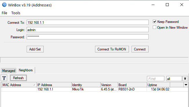
Для данного действия будет необходима программа WinBox, которую можно скачать на официальном сайте компании MikroTik www.mikrotik.com. Запустим программу, в нижнем окошке выберем Вам роутер (по умолчанию IP адрес 192.168.1.1 или 192.168.88.1) и введем имя пользователя и пароль, после чего нажимаем кнопку Connect
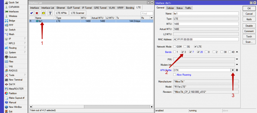
Затем перейдем в Interfaces -> LTE -> LTEAPNs
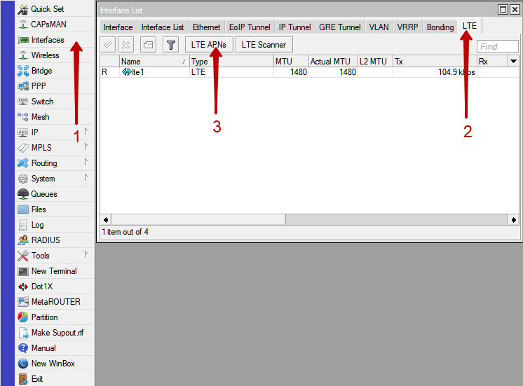
Нажимаем на + ,
далее в графе Name пишем OTK, а в графе APN прописываем точку
доступа, зависящую от базового оператора связи.
Для
Мегафона otk.msk
Для
Tele2
otk.tele2.ru
Для
Beeline home.beeline.ru
После нажимаем кнопку
OK
Далее дважды нажимаем на lte1. В новом окошке выбираем частоты. Для этого в графе Network Mode оставляем флажок только на LTE, в графе Bands оставляем только те частоты, которые используются в России. Это 3,7,20 соответственно.
Точка доступа MikroTik LtAP mini LTE kit одним из лучших выборов для организации подключения к сети интернет в автомобиле или организациям, которым необходимо резервирование канала для бесперебойной работы интернета. Устройство зарекомендовало себя только с положительной стороны в проектах различного уровня сложности: от подключения в рядовом бизнес-центре с монопольным провайдером интернета до подключения в машинах быстрого реагирования.
Компактный 4G/WiFi-роутер Mikrotik, известного латвийского производителя сетевого оборудования, обладающий широкими возможностями интеграции со сложными вычислительными, коммуникационными и промышленными системами. Внутренняя архитектура LtAP mini LTE kit построена вокруг производительного процессора QCA9531 с частотой 650 МГц, обеспечивающего высокую скорость обработки данных. За поддержку мобильного интернета отвечает сотовый модуль R11e-LTE, совместимый с большинством действующих на территории России стандартов мобильной связи.
Модем R11e-LTE не привязан к конкретному мобильному оператору и работает со всеми современными 3G/4G-стандартами (в том числе LTE800, LTE1800 и LTE2600). Среди достоинств MikroTik LtAP mini — наличие двух независимых SIM-слотов (Mini-SIM), позволяющих «черпать» трафик двух операторов сотовой связи по заранее назначенному расписанию или в режиме резервирования одного из каналов связи.
Представленная модель роутера оснащена двумя встроенными LTE-антеннами для работы роутера в зоне уверенного приема сигнала. При необходимости штатные антенны могут быть заменены выносными антеннами, подключаемыми через разъемы SMA-female. В базовом исполнении роутера SMA-разъемы на корпусе отсутствуют, а на посадочных местах установлены заглушки. Для установки внешних разъемов пользователю потребуется дополнительно приобрести пигтейл с коннекторами U.FL и SMA-female. Также возможна установка дополнительного разъема для подключения внешней GPS-антенны (требуется для использования GPS-датчика).
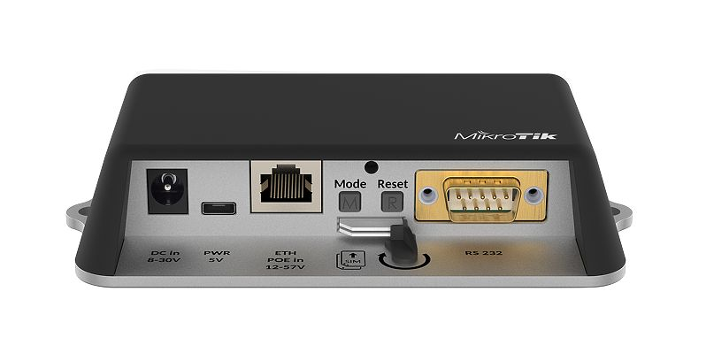
Разъемы передней панели роутера скрыты под защитной крышкой. Защитная крышка оснащена заглушками, удаляемыми по желанию пользователя, что обеспечивает удобную заводку кабеля в устройство.
Ethernet-порт предназначен для подключения роутера к компьютеру или коммутатору, а также для питания по технологии PoE (Passive PoE или 802.3af/at). Данная технология позволяет обеспечить питание роутера по тому же кабелю (витой паре), по которому передаются данные. Помимо PoE, для питания может использоваться порт Micro-USB и обычный блок питания.
Также в распоряжении пользователей имеется последовательный порт RS232 — промышленный интерфейс, который применяется для решения различных прикладных задач. Как правило, RS232 используется для опроса датчиков и измерительного оборудования, слежения за технологическим процессами и опроса различного узкоспециализированного оборудования.
Управление роутером LtAP mini осуществляется с помощью фирменной операционной системы RouterOS. Программное обеспечение MikroTik получило широкую известность среди системных администраторов и IT-экспертов: на сегодняшний день это одна из самых гибко настраиваемых сетевых платформ.
Компактность и многофункциональность LtAP mini LTE kit позволяет использовать роутер в системах различного назначения и специфики условий эксплуатации. Это устройство можно использовать в составе автомобильного усилителя 4G-интернета, платежного терминала, автомата вендинговой торговли, банкомата, охранной системы или промышленного технологического оборудования. Невысокая цена, надежность, компактность, высокие технические характеристики и открытые возможности интеграции — все это MikroTik LtAP mini!
Чтобы купить LtAP mini LTE kit, оформите заказ онлайн или свяжитесь с нашими менеджерами по номеру 8-800-3333-965. Мы порекомендуем лучшие решения под ваши задачи и запросы!
Роутер MikroTik LtAP mini LTE kit — буклет [PDF, ~370Kb]
Роутер MikroTik LtAP mini LTE kit — инструкция по подключению [PDF, ~450Kb]
| Характеристики | |
| Частотные диапазоны |
2G: 850/900/1800/1900 МГц 3G: 850/900/1900/2100 МГц LTE FDD: Band 1/2/3/7/8/20 (2100/1900/1800/2600/900/800 МГц) LTE TDD: Band 38/40 (2600/2300 МГц) |
| Категория LTE | LTE Cat. 4 (скорость загрузки до 150 Мбит/с) |
| Количество SIM-карт | 2 |
| Формат SIM | Mini-SIM |
| Диапазон WiFi | 2.4 ГГц |
| Максимальная скорость WiFi | 300 Мбит/с |
| Антенна WiFi | встроенная всенаправленная с коэффициентом усиления 1,5 дБи |
| GPS-модуль | MT3337V (коннектор U.FL на плате, требуется подключение внешней антенны) |
| Процессор | QCA9531 650 МГц |
| Оперативная память | 64 МБ |
| Внутренняя память | 16 МБ |
| Порты и интерфейсы роутера |
1 x Ethernet (10/100 Мбит/с) 1 x Micro-USB 2 x Mini-SIM 1 x DB9 (интерфейс RS232) |
| Операционная система | MikroTik RouterOS, 4 уровень лицензии |
| Питание |
адаптер питания 8–30В Passive PoE 10–57В или 802.3af/at Micro-USB 5В |
| Максимальное энергопотребление | 9 Вт |
| Диапазон рабочих температур | от -40°С до +70°С |
| Размер роутера | 139 x 77 x 28,5 мм |
| Вес роутера | 203 г |
| Комплектация | роутер, PoE-инжектор, адаптер питания, дополнительный кабель питания, набор метизов, инструкция |
Нет отзывов об этом товаре.
Написать отзыв об этом товаре
Ваше имя:*
Оценка:*
Ужасно
Отлично
Текст отзыва:*
Добавьте фото (до 5 штук):
Введите код, указанный на картинке:*
LtAP mini kit-series
LtAP mini LTE series user manual for models:
LtAP mini LTE kit (RB912R-2nD-LTm&R11e-LTE)
LtAP mini LTE kit-US (RB912R-2nD-LTm&R11e-LTE-US)
LtAP mini 4G kit (RB912R-2nD-LTm&R11e-4G)
The LtAP mini LTE kit is a wireless access point with two SIM card slots. The LtAP mini LTE, 4G kit comes with a factory-installed card.
Safety Warnings
Before you work on any equipment, be aware of the hazards involved with electrical circuitry, and be familiar with standard practices for preventing
accidents.
Ultimate disposal of this product should be handled according to all national laws and regulations.
All installation methods for mounting an access point on any wall surface is subject to the acceptance of local jurisdiction.
The Installation of the equipment must comply with local and national electrical codes.
This product is intended to be mounted outdoors on a pole but can also be installed indoors. Please read the mounting instructions carefully before
beginning installation. Failure to use the correct hardware and configuration or to follow the correct procedures could result in a hazardous situation for
people and damage to the system.
Use only the power supply and accessories approved by the manufacturer, and which can be found in the original packaging of this product.
Read the installation instructions before connecting the system to the power source.
We cannot guarantee that no accidents or damage will occur due to the improper use of the device. Please use this product with care and operate at your
own risk!
In the case of device failure, please disconnect it from power. The fastest way to do so is by unplugging the power plug from the power outlet.
It is the customer’s responsibility to follow local country regulations, including operation within legal frequency channels, output power, cabling
requirements, and Dynamic Frequency Selection (DFS) requirements. All Mikrotik radio devices must be professionally installed.
The equipment is not tested for Outdoor use by UL.
Exposure to Radio Frequency Radiation:This MikroTik equipment complies with the FCC, IC, and European Union radiation exposure limits set forth for an
uncontrolled environment.This MikroTik device should be installed and operated no closer than 20 centimeters from your body, occupational user, or the
general public.
Connecting
Connect your Internet cable to the Ethernet port (this is optional if using LTE as the primary connection);
Install your modem using miniPCIe slot (optional);
Insert the SIM card into the SIM slot;
Connect the GPS antenna (see » «,optional);GPS usage
Choose your powering solution (see » «);Powering
Navigate to the network connections section on your computer and locate the wireless network named « «. Proceed to connect to it;
MikroTik-….
Configuration should be made via a wireless network using a web browser or mobile application. Alternatively, you can use the WinBox
configuration tool ;https://mt.lv/winbox
Open the in your web browser;https://192.168.88.1
User name: , and there is no password
admin
(or, for some models, check user and wireless passwords on the sticker);
Update the device by clicking the (Check_for_updates) button to the latest RouterOS software for this to work the device needs to have an active
Internet connection;
To manually update the device without public IP, go to our download page d;https://mikrotik.com/downloa
Choose your architecture based on your device model under (System/Resources) and download the latest packages from a stable channel to
your PC;
Open WinBox and upload packages in the (Files) menu;
Reboot the device;
Reconnect and navigate to the
QuickSet
menu to select your country, which will implement the relevant country regulation settings;
Secure your device and set a strong password;
The following RouterOS «npk» packages are required for the product’s core functionality: gps, system.
- June 13, 2024
- Mikrotik
Table of Contents
- MikroTik LtAP Mini Wireless Access Point
- Product Information
- Product Usage Instructions
- Mounting Instruction
- Safety Warnings
- Connecting
- Mounting
- Powering
- Extension slots and ports
- miniPCIe slot usage
- GPS usage
- Buttons and jumpers
- Specifications
- Federal Communication Commission
- References
- Read User Manual Online (PDF format)
- Download This Manual (PDF format)
MikroTik LtAP Mini Wireless Access Point
Product Information
The LtAP mini (RB912R-2nD-LTm) is a wireless access point with two SIM card
slots for 3G/LTE data. It is designed for use with your own modem. The
equipment is not tested for outdoor use by UL. This MikroTik device complies
with the FCC, IC, and European Union radiation exposure limits for an
uncontrolled environment. It should be installed and operated no closer than
20 centimeters from your body, occupational user, or the general public.
Safety Warnings:
- The equipment is not tested for outdoor use by UL.
- The device should be installed and operated no closer than 20 centimeters from your body, occupational user, or the general public.
Product Usage Instructions
- Install your desired modem in the miniPCIe slot.
- If you intend to use GPS, an external antenna is required.
- Choose your powering solution.
- Connect your Internet cable to the Ethernet port.
- Set your computer IP configuration to automatic (DHCP).
- Connect your direct input power jack if not using PoE to start up the device.
- The device will boot up and the Wireless network will be available for connecting.
- Open network connections on your PC, mobile phone, or other device and search for the MikroTik wireless network and connect to it.
- Once connected to the wireless network, open https://mt.lv/winbox in your web browser to start the configuration.
- Since there is no password by default, you will be logged in automatically. Alternatively, for some models, check user and wireless passwords on the sticker.
- The configuration can also be done using the MikroTik mobile app (see MikroTik mobile app) or the WinBox configuration tool (https://mt.lv/winbox).
- We recommend clicking the Check for updates button and updating your RouterOS software to the latest version for the best performance and stability.
- Choose your country to apply country regulation settings and set up your password on the screen that loads.
Mounting Instruction
- Attach the device to a wall using the provided screw holes on the sides of the unit. Ensure that the cable openings are pointing downward.
- Use a Philips PH2 screwdriver to access the ports, which are protected with a small door held in place with one screw.
- Break out only the openings that you will use on the door, which has cut-out places for all available ports.
- The device can be used both indoors and outdoors, with an IP rating scale of IP54.
- If mounting outdoors, ensure that any cable openings are directed downwards. Use a PoE injector and proper grounding. It is recommended to use Cat6 cable.
- For external LTE and GPS antennas, drill openings in the device enclosure that are appropriate for the antenna cable used. Alternatively, you can obtain a DINrail Pro – mounting bracket designed to fit standard 35 mm x 7.5 mm DIN rails (https://mikrotik.com/product/dinrail_pro).
- The mounting and configuration of this device should be done by a qualified person.
LtAP mini (RB912R-2nD-LTm)
The LtAP mini is a wireless access point with two SIM card slots for 3G/LTE
data. The LtAP mini is designed for use with your own modem.
Safety Warnings
- Before you work on any equipment, be aware of the hazards involved with electrical circuitry, and be familiar with standard practices for preventing accidents.
- Ultimate disposal of this product should be handled according to all national laws and regulations.
- All installation methods for mounting an access point on any wall surface is subject to the acceptance of local jurisdiction.
- The Installation of the equipment must comply with local and national electrical codes.
- This product is intended to be mounted outdoors on a pole but can also be installed indoors. Please read the mounting instructions carefully before beginning installation. Failure to use the correct hardware and configuration or to follow the correct procedures could result in a hazardous situation to people and damage to the system.
- Use only the power supply and accessories approved by the manufacturer, and which can be found in the original packaging of this product.
- Read the installation instructions before connecting the system to the power source.
- We cannot guarantee that no accidents or damage will occur due to the improper use of the device. Please use this product with care and operate at your own risk!
- In the case of device failure, please disconnect it from power. The fastest way to do so is by unplugging the power plug from the power outlet.
- It is the customer’s responsibility to follow local country regulations, including operation within legal frequency channels, output power, cabling requirements, and Dynamic Frequency Selection (DFS) requirements. All Mikrotik radio devices must be professionally installed.
- The equipment is not tested for Outdoor use by UL.
Exposure to Radio Frequency Radiation: This MikroTik equipment complies
with the FCC, IC, and European Union radiation exposure limits set forth for
an uncontrolled environment. This MikroTik device should be installed and
operated no closer than 20 centimeters from your body, occupational user, or
the general public.
Connecting
- Install your desired modem (see “miniPCIe slot usage”).
- If the intent to use GPS, an external antenna is required (see “GPS usage”).
- Choose your powering solution (see “Powering”).
- Connect your Internet cable to the Ethernet port.
- Set your computer IP configuration to automatic (DHCP).
- Connect your direct input power jack if not using PoE, to start up the device.
- The device will boot up and the Wireless network will be available for connecting.
- Open network connections on your PC, mobile phone, or other device and search for MikroTik wireless network and connect to it.
- Once connected to the wireless network, open in your web browser to start configuration, since there is no password by default, you will be logged in automatically (or, for some models, check user and wireless passwords on the sticker). The configuration also can be done using a mobile app (see “MikroTik mobile app”), and WinBox configuration tool https://mt.lv/winbox .
- We recommend clicking the “Check for updates” button and updating your RouterOS software to the latest version to ensure the best performance and stability.
- Choose your country, to apply country regulation settings, and set up your password on the screen that loads.
- *The following RouterOS “npk” packages are required for the core functionality of the product: gps, system.
Mounting
- It is possible to attach the device to a wall, using the provided screw holes on the sides of the unit. The device should be mounted in a way that the cable openings are pointing downward as shown in the picture.
- The ports are protected with a small door, that is held in place with one screw. Use the Philips PH2 screwdriver to access the ports.
- The door has cut-out places for all available ports, but please only break out the openings that you will use. The device can be used both indoors and outdoors. The IP rating scale for this device is IP54.
- The device enclosure has places where you can drill openings for external LTE and GPS antennas. Use a drill to make holes that are appropriate for the antenna cable used.
Alternatively, you can obtain a “DINrail Pro” – mounting bracket, designed to
fit standard 35 mm x 7.5 mm DIN rails.
https://mikrotik.com/product/dinrail_pro
When mounting outdoors, please ensure that any cable openings are directed
downwards. Use a PoE injector and proper grounding. Recommended using Cat6
cable.
Warning! This equipment should be installed and operated with a minimum
distance of 20 cm between the device and your body. The operation of this
equipment in the residential environment could cause radio interference.
The mounting and configuration of this device should be done by a qualified
person.
Powering
All voltages are in compliance with ES1 and max. PS2/LPS according to EN IEC
62368-1.
Input Voltage|
- DC plug: 8-30 VDC
- USB: 5 VDC
- PoE: 8-57 VDC
—|—
Input Power| 9W
- Direct-input power jack (5.5 mm outside and 2 mm inside, female, pin positive plug) accepts 8-30 V DC.
- microUSB port accepts 5 V powering.
- Ethernet port accepts passive and 802.3af/at Power over Ethernet 8-57 V DC (compensate for loss on cable, so more than 12 V recommended).
The power consumption under maximum load with attachments can reach 9 W.
Connecting to a PoE Adapter:
- Connect the Ethernet cable from the device to the PoE+DATA port of the PoE adapter.
- Connect an Ethernet cable from your local network (LAN) to the PoE adapter.
- Connect the power cord to the adapter, and then plug the power cord into a power outlet.
Extension slots and ports
- Built-in 2 GHz wireless access point module, AP/station/bridge/p2p modes are supported. Onboard PIF antennas built-in. Antenna gain1.5 dBi.
- miniPCIe slot and two SIM slots (can’t be used without a modem installed, can’t be used both at the same time) to be used with a 3G/4G/LTE modem. Onboard antennas available, but openings for external antennas are provided on the case.
- Built-in GPS module – uFL connector provided for an external antenna. To enable, set the port to serial0 (this disables the DB9 port on the unit). Supports – GPS, GLONASS, BeiDou, Galileo).
- One 10/100 Ethernet port, supporting automatic cross/straight cable correction (Auto MDI/X). Either straight or crossover cable can be used for connecting to other network devices. The Ethernet port accepts 12-57 V DC powering from a passive PoE injector.
- One DB9 RS232 serial port for serial console access. Configured as 115200 bit/s, 8 data bits, 1 stop bit, no parity. Can’t be used if built-in GPS is enabled on serial0.
- One microUSB 2.0 port for powering only.
Configuration
- RouterOS includes many configuration options in addition to what is described in this document. We suggest starting here to get yourself accustomed to the possibilities: https://mt.lv/help . In case IP connection is not available, the Winbox tool ( https://mt.lv/winbox ) can be used to connect to the MAC address of the device from the LAN side (all access is blocked from the internet port by default).
- For recovery purposes, it is possible to boot the device from the network, see section Buttons and jumpers.
miniPCIe slot usage
The device is equipped with a miniPCIe slot to be used with a 3G/4G/LTE modem.
Two SIM slots are provided for use together with a miniPCIe modem. The SIM
slot is not used separately.
In this case, an internal antenna is not connected (located inside the
enclosure). Installing a miniPCIe module should be done by a qualified person,
please follow safety precautions when handling electrical equipment:
- Use a wrist grounding strap when unpacking and working with electrical components to avoid electrical discharge (ESD) damage.
- Open the front cover by unscrewing one screw with the Philips PH2 screwdriver.
- Remove four screws on the bottom of the case and lift off the top part of the case. You will see the antenna attached to it.
- Locate the mini PCIe slot on the PCB and remove two factory attached screws.
- Attach provided a thick thermal pad to the card, and install the card into miniPCIe slot so that the thermal pad is between PCB and card.
- The secure card in place using previously removed two screws.
- Attach the grey uFL connector to the MAIN antenna connector of the modem, attach the black cable to the secondary (or AUX) connector.
- To use external antennas, attach antenna connectors and use a 6.5 mm drill bit to drill holes on the side of the unit. (see “Mounting”) description 4.
- Please see the picture below on how to place rubber seals for the best water protection.
- Attach antenna connectors to the installed card and GPS connector on the PCB, as additional rubber silicone can be used to secure connectors in place on card and PCB board.
- Attach a thinner thermal pad to the top of the card.
- Reassembly in backorder.
- After you have reinserted the device into the case and secured it with the screws that were removed earlier, slide in the SIM cards from your mobile operator into the SIM slots, with the chips facing as shown on the port label. The slot accepts miniSIM (2FF). Close the black latch for SIM cards, to secure them in the slots.
GPS usage
- In order to use GPS, an external antenna is needed to connect.
- We recommend to use the “ACGPSA” – can be obtained separately. ACGPSA is a standalone active GPS antenna, that works in the 1575.4 MHz spectrum. Antenna size is 46.5 mm x 26.5 mm x 12.5 mm with an IP67 rating and includes an internal magnet and double-sided tape, so it can easily be attached to various surfaces. It has a long 5m cable with an SMA connector, to be connected to LtAP mini via the ACSMAUFL pigtail (not included, product code ACSMAUFL)
- https://mikrotik.com/product/acgpsa
- https://mikrotik.com/product/acsmaufl
- To connect a GPS antenna, see “miniPCIe slot usage” step 10.
Supports – GPS, GLONASS, BeiDou, Galileo).
Configuration information –
https://wiki.mikrotik.com/wiki/Manual:System/GPS#Basic_examples
The GPS uses an active antenna, connect only when power is turned off.
Buttons and jumpers
Reset button
- Hold this button during boot time until LED light starts flashing, release the button to reset RouterOS configuration (total 5 seconds).
- Keep holding for 5 more seconds, LED turns solid, release now to turn on CAP mode. The device will now look for a CAPsMAN server (total 10 seconds).
- Or keep holding the button for 5 more seconds until LED turns off, then release it to make the RouterBOARD look for Netinstall servers (total 15 seconds).
Regardless of the above option used, the system will load the backup
RouterBOOT loader if the button is pressed before power is applied to the
device. Useful for RouterBOOT debugging and recovery.
Mode button
The action of the mode buttons can be configured from RouterOS software to
execute any user-supplied RouterOS script. You can also disable this button.
The mode button can be configured in RouterOS menu /system routerboard mode-
button
Accessories
Package includes the following accessories that come with the device:
- DC ⎓ Switching Power Supply 24 V, 1.2 A, 28.8 W, 86.8 %, VI, cable:220 cm RA DC.
- Cable DC ⎓ plug RA 5.5×2.1×10.5 to Striped 2*24 AWG Tin 8 mm, length 0.35 m.
- PoE Injector with shielded Ethernet cable/connector (RBPoE).
- DC ⎓ 24 V 1.2 A power adapter.
- Mounting kit K-55 VMS.
- Elastic thermal pad, 25x40x3.5 mm.
Specifications
For more information about this product, specification and pictures please
visit our web page: https://mikrotik.com/product/ltap_mini
Operating system support
The device supports RouterOS software version 6. The specific factory-
installed version number is indicated in the RouterOS menu /system resource.
Other operating systems have not been tested.
MikroTik mobile app
Use the MikroTik smartphone app to configure your router in the field, or to
apply the most basic initial settings for your MikroTik home access point.
- Scan QR code and choose your preferred OS.
- Install and open application.
- By default, the IP address and user name will be already entered.
- Click Connect to establish a connection to your device through a wireless network.
- Choose Quick setup and application will guide you through all basic configuration settings in a couple of easy steps.
- An advanced menu is available to fully configure all necessary settings.
To avoid pollution of the environment, please separate the device from
household waste and dispose of it in a safe manner, such as in designated
waste disposal sites. Familiarize yourself with the procedures for the proper
transportation of the equipment to the designated disposal sites in your area.
Federal Communication Commission
Interference Statement
| Model | FCCID |
|---|---|
| RB912R-2nD- LTm | TV7RB912R- 2NDLTM |
- This equipment has been tested and found to comply with the limits for a Class B digital device, pursuant to Part 15 of the FCC Rules. These limits are designed to provide reasonable protection against harmful interference in a residential installation.
- This equipment generates, uses, and can radiate radio frequency energy and, if not installed and used in accordance with the instructions, may cause harmful interference to radio communications.
- However, there is no guarantee that interference will not occur in a particular installation. If this equipment does cause harmful interference to radio or television reception, which can be determined by turning the equipment off and on, the user is encouraged to try to correct the interference by one of the following measures:
- Reorient or relocate the receiving antenna.
- Increase the separation between the equipment and receiver.
- Connect the equipment into an outlet on a circuit different from that to which the receiver is connected.
- Consult the dealer or an experienced radio/TV technician for help.
FCC Caution: Any changes or modifications not expressly approved by the
party responsible for compliance could void the user’s authority to operate
this equipment.
This device complies with Part 15 of the FCC Rules. Operation is subject to
the following two conditions:
- This device may not cause harmful interference, and
- This device must accept any interference received, including interference that may cause undesired operation.
This device and its antenna must not be co-located or operation in conjunction
with any other antenna or transmitter.
IMPORTANT: Exposure to Radio Frequency Radiation.
This equipment complies with the FCC RF radiation exposure limits set forth
for an uncontrolled environment. This equipment should be installed and
operated with a minimum distance of 20 cm between the radiator and any part of
your body.
Innovation, Science and Economic Development Canada
| Model | IC |
|---|---|
| RB912R-2nD- LTm | 7442A- 912R2NDLTM |
This device complies with Industry Canada’s licence-exempt RSS standard(s).
Operation is subject to the following two conditions:
- this device may not cause interference, and
- this device must accept any interference, including interference that may cause undesired operation of the device.
IMPORTANT: Exposure to Radio Frequency Radiation.
This equipment complies with the IC radiation exposure limits set forth for an
uncontrolled environment. This equipment should be installed and operated with
a minimum distance of 20 cm between the radiator and any part of your body.
CE Declaration of Conformity
- Manufacturer: Mikrotikls SIA, Brivibas gatve 214i Riga, Latvia, LV1039.
- Hereby, Mikrotīkls SIA declares that the radio equipment type RB912R-2nD-LTm is in compliance with Directive 2014/53/EU. The full text of the EU declaration of conformity is available at the following internet address: https://mikrotik.com/products
Frequency bands terms of use
Frequency range (for applicable models)| Channels used| Maximum Output Power
(EIRP)| ****
Restriction
—|—|—|—
2400-2483.5 MHz| 1 – 13| 20 dBm| Without any restriction to use in
| | | all EU Member States
—|—|—|—
-
- It is the customer’s responsibility to follow local country regulations, including operation within legal frequency channels, output power, cabling requirements, and Dynamic Frequency Selection (DFS) requirements. All MikroTik radio devices must be professionally installed!
- This MikroTik device meets Maximum WLAN transmit power limits per ETSI regulations. For more detailed information see Declaration of Conformity abov
Note. The information contained here is subject to change. Please visit
the product page on www.mikrotik.com for the most
up to date version of this document.
References
- MikroTik Routers and Wireless
- MikroTik Routers and Wireless — Buy
- MikroTik Routers and Wireless — Buy
- MikroTik Routers and Wireless — Products: ACSMAUFL
- MikroTik Routers and Wireless — Products: DINrail PRO
- Manual:System/GPS — MikroTik Wiki
Read User Manual Online (PDF format)
Read User Manual Online (PDF format) >>
Download This Manual (PDF format)
Download this manual >>