
Table of Contents
- FVTLED Mini Wifi LED Controller
- FAQ
- Product Parameter
- Wire Connection
- Connection schematic diagram
- How to reset the factory setting
- Download FVTLED APP
- Read User Manual Online (PDF format)
- Download This Manual (PDF format)
FVTLED Mini Wifi LED Controller
Product Specifications
- Category: LED Controller
- Operation Platform: FVTLED App
- Channels: 3
- Input Voltage: DC 12-24V
- Max Output Power: 100W
- Working Temperature: -20°C to +55°C
- Control Distance: Visible distance 30m
- Certification: CE, RoHS, FCC
- Net Weight: 33.5g
- Dimensions (LWH): 53mm x 24mm x 11mm
- Carton Size (LWH): 50cm x 25cm x 21cm
Wire Connection
The connection between the controller and the power supply must be made
correctly to avoid short circuits. Ensure the arrows on the controller match
those on the device.
Key Instruction
- ON/OFF: Power control
- Night Light Mode: Activates night light mode
- Color Temperature (+): Increase warmth level
- Brightness (+): Increase brightness level
- Color Temperature (-): Increase cold light level
- Brightness (-): Decrease brightness level
- RGB Color Cycle Mode: Three-speed RGB color cycle
FVTLED App Usage Instructions
- Download the FVTLED App from the App Store or Google Play Store, or scan the QR code provided.
- Login or register your FVTLED account.
- In the app, tap “Add Device” or click on the plus sign to add the controller. Select your Wi-Fi network (works only with 2.4GHz networks) and enter the password.
- You can modify the device name and select the room after successfully connecting to the Wi-Fi network.
How to Reset to Factory Settings?
- Before resetting, ensure the device is powered on.
- To reset, turn on the light, then turn it off three times in quick succession. Keep the light off for 5 seconds after the third turn-off.
FAQ
Q: How do I connect the controller to a Wi-Fi network?
A: Register/log in to your FVTLED account, then follow the steps in the
FVTLED app to connect to your Wi-Fi network.
Q: Where can I find more information about the product?
A: Scan the instruction QR code for the electronic manual or visit the
APP FAQ section for more details.
Product Parameter
- Category: LED Controller
- Domination Principle: WiFi
- APP: FVTLED
- Operation Platform: Android 7.0or IOS 12.3 or later
- Channels: GRB/RGBW
- Input Voltage: DC(12-24)V
- Max Output Power: 100W
- Working Temperature: -20~+55℃
- Control Distance: Visible distance 30M
- Certification: CE, RoHS, FCC
- Net Weight: 33.5g
- Dimension(LBH): 53MM24MM11MM
- Carton Size(LBH): 50CM25CM21CM
Wire Connection
Connection schematic diagram
- The connection between the controller and the power supply
- Controller and device connection


Notice:
It is necessary to ensure that the red arrow of the controller corresponds to
the black arrow of the device end otherwise the the device will have a short
circuit.
Important Notice:
If you need to make DIY modifications to the device, please contact our
customer service and operate under their guidance. Precautions:Please follow
the diagram instruction when doing DIY modifications
Key Instruction

How to connect the controller to Wi-Fi network
- Register/Login your FVTLED account.
- Open your phone Bluetooth, turn on the device.
- Enter“ FVTLED ” app, tap“ Add Device” or click“ +” to add the device. Then select your Wi-Fi network(Only work with 2.4Ghz network), enter the password
- The device name can be modified and select the room after successfully connecting to Wi-Fi network


How to reset the factory setting

Download FVTLED APP
Download“ FVTLED ” APP from App store and Google Play Store, or scan the QR
code. ****
FAQ
Scan the ” Instruction ” QR code to read the electronic manual Or enter the
APP FAQ to learn more
Read User Manual Online (PDF format)
Read User Manual Online (PDF format) >>
Download This Manual (PDF format)
Download this manual >>
Умный WiFi RGB LED — контроллер Smart Aura SA-CTR-360 для светодиодной ленты на 4 контакта.
ВНИМАНИЕ! Перед установкой необходимо отключить питание, чтобы предотвратить удар электрическим током. Для работы контроллера требуется блок питания постоянного тока 12 или 24 вольт.
Обозначения контактной группы
Настройка в приложении
Все умные WiFi устройства Smart Aura и в том числе котроллер подключаются по WiFi 2.4 ГГц. Подключить и добавить умный LED-контроллер можно через несколько приложений:
Smart Life, Tuya Smart, DIGMA SmartLife.
Найдите его в магазине приложений своего смартфона. Если у вас нет зарегистрированного аккаунта, зарегистрируйтесь в приложении используя e-mail. Все приложения интуитивно понятны, вы с легкостью сможете добавлять умные устройства всего дома. (ВАЖНО! Если вы планируете интеграцию с VK Маруся или Сбер Салют, то устанавливайте и добавляйте контроллер в приложение DIGMA SmartLife, так как эти голосовые помощники имеют интеграцию только с этим приложением).
После того как вы войдете используя логин и пароль включите Bluetooth и WiFi (2.4ГГц) на своем смартфоне. Зажмите кнопку включения на самом контроллере (не на пульте) на 5-7 секунд. Светодиодная лента загорится красным цветом и начнет мигать, значит контроллер перешел в режим поиска. В приложении в правом верхнем углу нажмите значок «+» далее «Добавить устройство» (как показано на рисунке ниже).
Если устройство не появилось автоматически, выберите его из списка «Полосы света» в разделе «Освещение» или «Лампа» в альтернативных приложениях (как показано на рисунке ниже).
Далее следуйте подсказкам в приложении, согласитесь с тем что индикатор мигает (как показано на рисунке ниже).
Далее введите название и пароль вашей WiFi сети, нажмите «Далее» (как показано на рисунке ниже). После подключения дайте название устройству и отнесите его к комнате (если вам это требуется).
Для интеграции с голосовым помощником, перейдите в специальное приложение и найдите пункт: добавить -> устройство умного дома. Выберете и синхронизируйте аккаунт Smart Life или DIGMA SmartLife. После синхронизации все добавленные устройства появятся в приложении голосового помощника.
Подробная инструкция как интегрировать Smart Life или Tuya в Умный дом с Алисой
Подробная инструкция как интегрировать DIGMA Smartlife в приложение Маруся
Подробная инструкция как интегрировать DIGMA Smartlife в приложение Сбер Салют
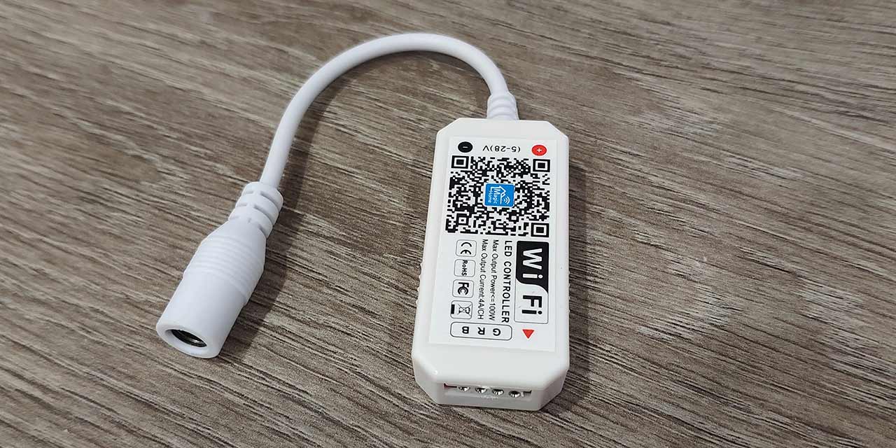
Wi-Fi контроллер предназначен для управления RGB-светодиодной лентой через приложение Magic Home Pro на смартфоне. Контроллер выполнен из пластикового корпуса, с одной стороны имеется коннектор 4-pin Father для подключения ленты, а с другой стороны разъем Power Jack 5,5 мм Mother для подачи питания 12В.
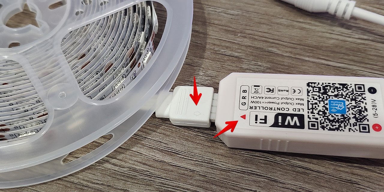
При подключении ленты к контроллеру необходимо убедится, что красная стрелка на контроллере совпадает с выпуклой стрелкой на коннекторе RGB-ленты.
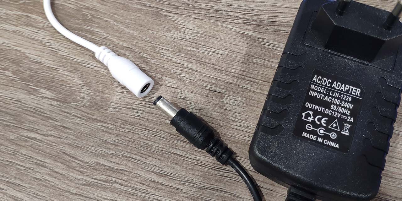
Затем подаем питание к контроллеру через блок питания 12В.
Теперь при помощи сканера QR-кодов на смартфоне сканируем QR-код на корпусе Wi-Fi контроллера. Ссылка ведет на страницу сайта, где можно скачать APK-Файл для установки приложения Magic Home Pro.
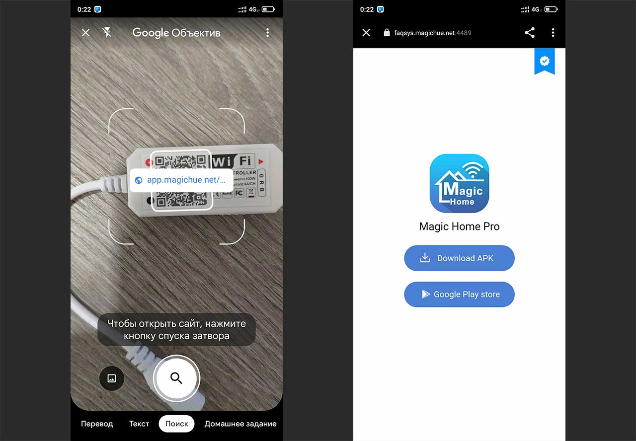
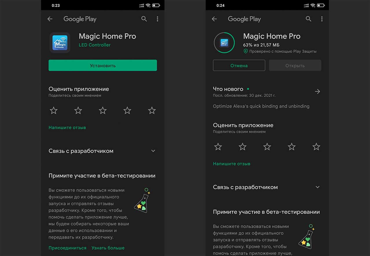
Так же можно использовать приложение Google Play на Android-смартфоне для поиска и загрузки приложения Magic Home Pro.
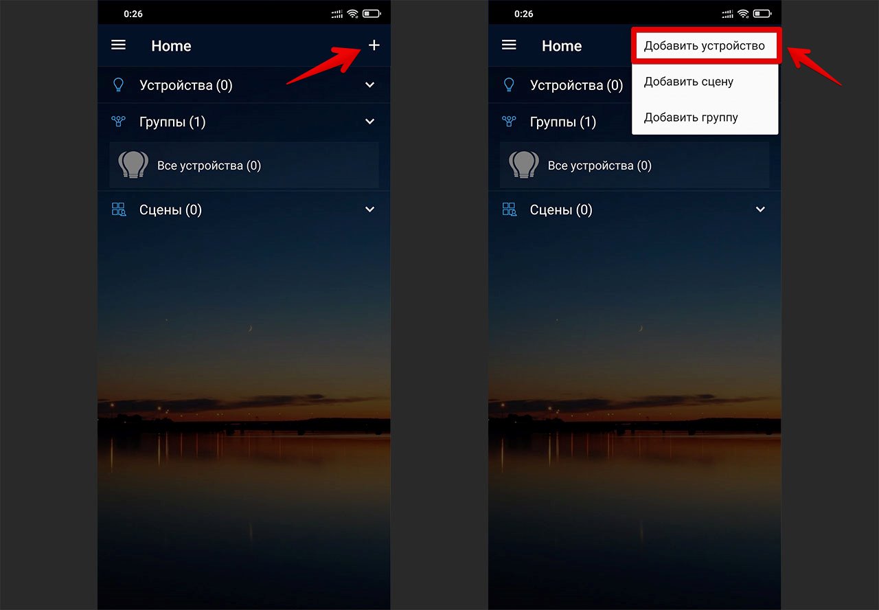
После установки переходим в приложение, нажимаем на плюс в правом верхнем углу экрана. В появившемся меню выбираем «Добавить устройство».
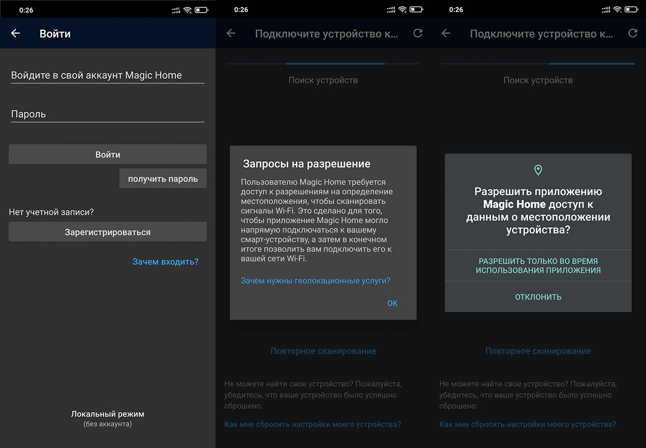
Регистрируемся и авторизовываемся под своей учетной записью. Затем разрешаем приложению все необходимые доступы.
В окне подключения устройства выбираем контроллер. Название будет соответствовать «LEDnetXXXXXX«. Для подключения к контроллеру нажимаем кнопку «Подключить«.
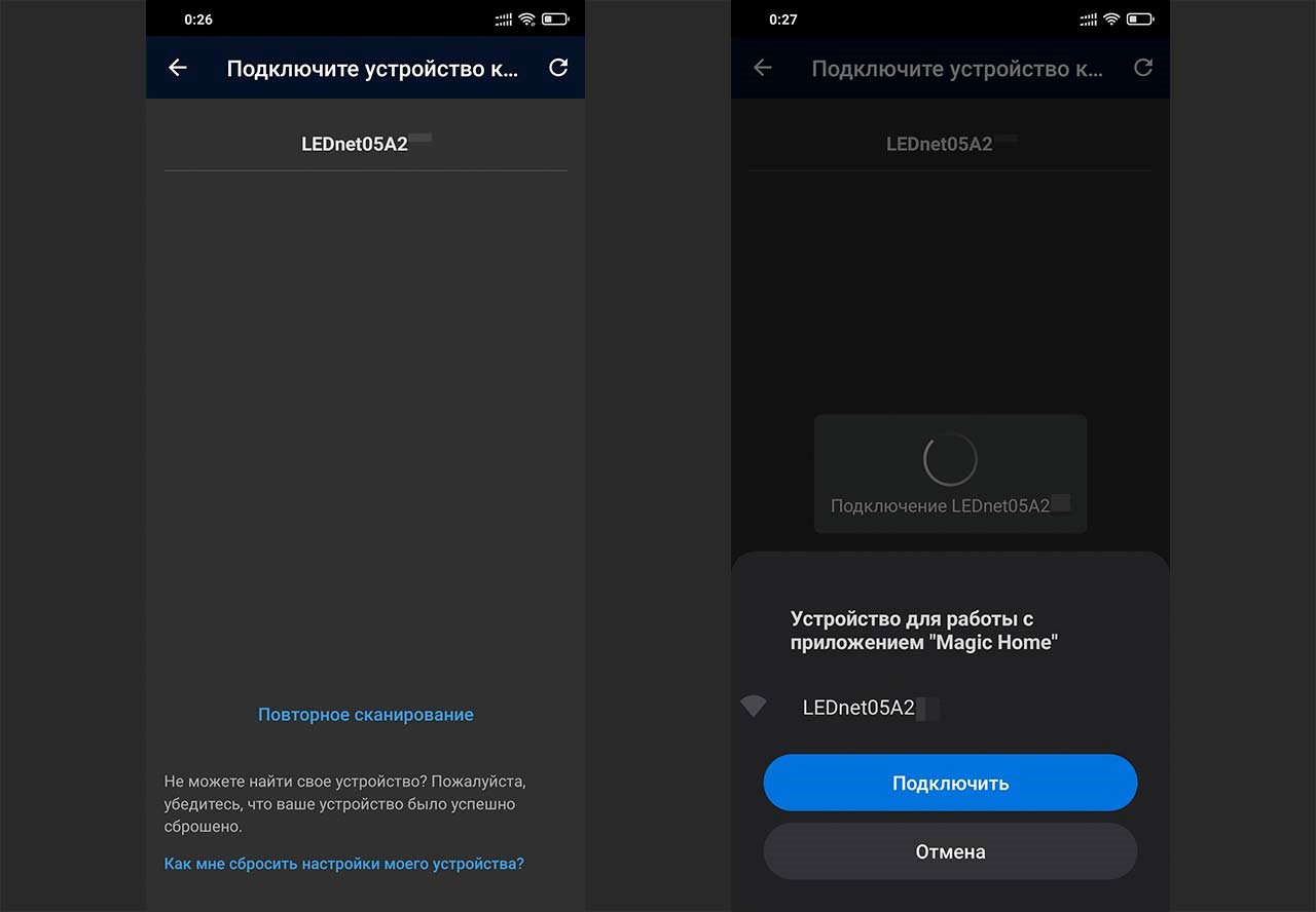
В следующем окне выбираем домашнюю Wi-Fi сеть, к которой хотим подключить Wi-Fi контроллер и вводим от неё пароль.
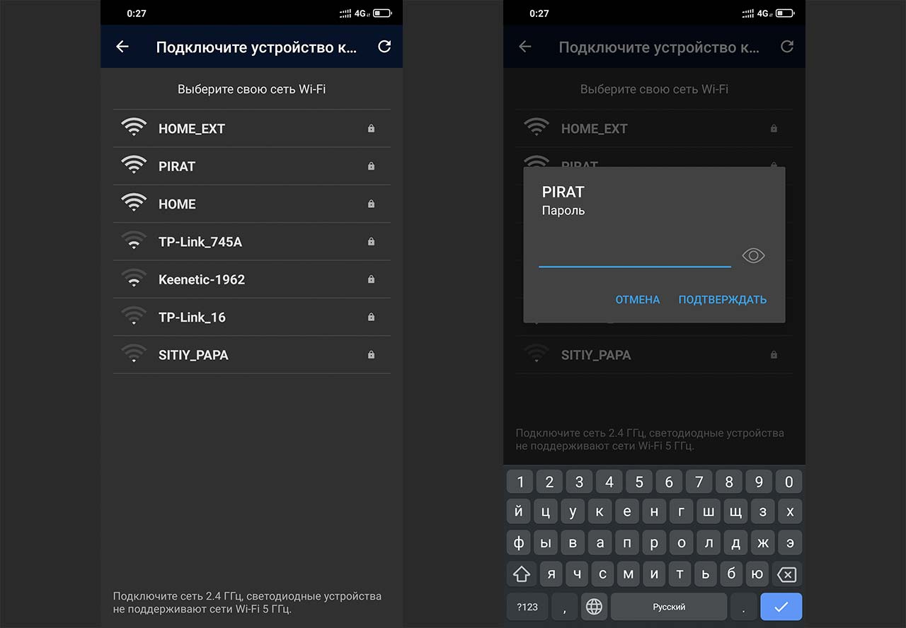
После успешного добавления контроллера появится окно, в котором можно ввести название текущего контроллера. При запуске приложения Magic Home Pro в разделе «Устройства» будет отображаться Wi-Fi контроллер при клике на который появится меню для управления подсветкой ленты.

Table of Contents
- Buy
- Details
- Specifications
- Assembly Instructions
Buy
For fast shipping to the US, you can buy from our Tindie store.
If we’re out of stock on Tindie, or for free shipping worldwide, you can contact us to order and have them shipped to you directly from the PCB manufacturer. It takes a bit longer, and they require PCBs be ordered in multiples of three.
Details
This is a shield/breakout for the Wemos D1 Mini (and D1 Mini Pro) ESP8266 board that makes it easy to control addressable RGB LEDs, such as WS2811, WS2812 (Adafruit NeoPixels), and APA102 (Adafruit DotStars). The Wemos D1 Mini is an excellent mini Wi-Fi development board, based on the ESP8266. I’ve used it extensively in development of addressable RGB LED art projects, such as my 6.5ft Rainbow Tree, Bloom v2, and Ducenti.
This is a smaller version of my Wemos D1 Mini ESP8266 LED & Level Shifter Shield.
I made this shield because I was hand-wiring this same layout on perma-proto boards, which was time-consuming and unprofessional looking.
The shield includes the slightly smaller 74HCT125 level shifter. It belongs to the same family as the 74HCT245, which is the most well-regarded high speed level shifter I’ve found. This shifts the 3.3V logic level of the ESP8266 to the 5V expected by addressable RGB LEDs. These projects often work fine without a level shifter, until they don’t.
Four digital output pins (D5 — D8) are run through the level shifter. These pins support parallel output by the fantastic FastLED library.
The shield also includes places for data line resistors as recommended when driving LEDs. Duplicate breakouts are included for each of the Wemos D1 mini pins. This shield omits the large 1000uF capacitor included on the larger shield, due to limited space. The large capacitor can be connected across the power and ground connections at the strip.
Specifications
- Size: 1.02 x 1.10 x .063 inch (25.83 x 27.89 x 1.6 mm)
- 2 layer printed circuit board
- FR4 substrate
- Lead free
- Purple SMOBC (solder mask over bare copper)
- ENIG (Electroless Nickel Immersion Gold) finish
- Manufactured in the USA
Parts that are not included, but are required to assemble:
- Wemos D1 Mini
- SN74HCT125N Level Shifter
- 0.10µF Capacitor
- 330 Ohm resistors
Wire/Connectors
- Pre-Wired JST SM Connectors
OR
- JST-SM connectors
- SN-48B Crimping Tool
- 22 AWG Wire
Assembly Instructions
Note: Double-check the position, alignment, and orientation of each component very carefully before soldering!
If you’re new to soldering, I highly recommend reading through a good soldering tutorial, such as the ones by Adafruit and SparkFun.
Note: Some WEMOS/LOLIN D1 Minis have the USB port on the top side, and some have it on the bottom side of the board. Either way, ensure the the button is in the lower-left corner, and the pins labels match the shield PCB:
-
Insert the SN74HCT125N Level Shifter chip into the holes in the top side of the board, where indicated, with the indentation towards the top edge of the board.
-
Flip the board over and solder one pin on the chip, pressing down on the PCB to ensure the chip is seated firmly.
-
Make sure the chip is still seated properly before proceeding to solder the rest of the pins.
-
Insert the 0.1uF capacitor, flip over and solder.
-
Insert a 300 Ohm to 500 Ohm resistor in each set of holes for each output you plan to use. Bend one leg 180 degrees around, flat against the resistor body, and insert it vertically.
-
Flip the board over and solder each leg of each resistor.
-
Decide whether you’re going to use female headers, stacking female headers, or if you’re going to solder the Wemos directly to the level shifter shield PCB. I used single female headers so the Wemos would be removable, but still fairly low profile.
-
I used double-sided male headers in a small breadboard to hold the female headers correctly aligned while I soldered.
-
Trim all the leads with a pair of wire cutters. Flush diagonal cutters work best.
-
I use pre-assembled 3 pin JST-SM connectors to connect the LEDs.
-
If possible, use a PCB vise to hold the PCB vertically, and a helping hands tool to hold the wires as they’re soldered.
-
With a small amount of solder on the tip of the iron, heat the wire right on the bottom of the pad.
-
Melt a fair amount of solder on the wire and pad. The insulation on the wire may start to melt as the wire heats up. If so, push the wire through the hole, from the top towards the bottom, to ensure no wire is left exposed on top.
-
Repeat this process for the other wires.
New Led WiFi Controller Led RGB Strip Controller WF400
Download User Guide
Product specification
Name:LED WIFI Controller
Model:KW-WF400
I. Product Summarization
1. Product constitution
|
NO. |
Name |
Instruction |
|
1 |
WF400 Controller |
It is the core of product, is responsible for receiving control signal and controlling LED equipment. |
|
2 |
disk |
Include mobile software of IOS operating system and Android operating system |
|
3 |
manual |
Detailed instructions of product using methods |
|
4 |
USB cable |
Using when connected with computer |
WF400 is another wifi controller independently developed by our company, following our WF100, compared with WF100, WF400 is more powerful, and more flexible to use, when using, you do not need to switch wireless networks, it is more convenient to be on internet. You can choose encrypt network, can also open network. It’s more convenient for you to choose wireless network with WiFiManager network management software, WF400 network configuration. Combined our independently developed mobile software Touchhome with controller, this makes the function of WF400 more better than WF100. Supporting the use of software with WF400, it can achieve single point control and group control, in addition, it includes some features, such as re-name of controller, set the location, timing control and other function. This makes the function of WF400 more powerful.
Trough the use of WIFI technology, it provides more comfortable, safer and more convenient intelligent lighting control than traditional lighting control, optimizes the lighting control methods, which brings a new, comfortable lighting environment to users.
II. Technical Parameters
1. Software technical parameters
1.1 Control software:
1. Name: Touch Home
2. Runtime platform: Android system (iphone, ipad), equipment must have WiFi function.
3. Language: English
4. Category: communications
5. Other: Free, no plug-ins
1.2 Configuration software
1. Name: WiFiManager
2. Runtime platform: Win 7/Windows Vista/Win2003/WinXP/Win2000
3. Language: English
4. Category: communications (USB)
5. Others: Free, no plug-ins
1. Working voltage: DC5-24V
2. Working temperature: -20-60℃
3. Working Power consumption: about 1.6W
4. Output: 3 channel common anode, Max. current4A/each channel, with over current protection
5. Packing dimension: L215 * W165 * H55(mm)
6. External dimension: L107 * W65 * H30(mm)
7. Controller weight: 340g
8. Remote control weight: 85g
9. Gross weight: 460g
10. Receiving sensitivity: 802.11b/g DSSS(-5dBm),802.11b CCK (-10dBm),802.11g OFDM(-15dBm)m)
3. Remote control technical parameters
1. Working temperature:-20-60℃
2. Power supply method:AAA*3
3. Supply voltage: 1.5V*3
4: Standby power: 0.015mW
5. Standby current:: 3uA
6. Working current: 200uA
7. Emission current: 10mA
8. Remote control distance: about 30m
9. Standby time: 6 month
III. Instruction for use
Proper use of WF400 mainly includes the following steps:
Step1:Recognize and identify the controller interfaces
Understand the function of each interface on the controller, its basic usage and wiring. Refer to the controller interface instructions.
Step 2: Configure the controller
Through WiFiManager, you can configure various parameters of the controller, including the name, location, network, time, output type and so on, facilitate user to recognize and control. Refer to WiFiManager instructions.
Step 3: Install controller
Understand specific wiring of controller and installation requirements. Refer to hardware installation instructions of controller.
Step 4: Remote control
Describes specific use of touch remote control. Refer to remote control instructions.
Step 5: Mobile phone control
Brief description control method of mobile phone. Refer to TouchHome instructions.
1. Controller Interface Description
1.1 Indicator Status Description
|
No. |
Indicator |
Function description |
|
1 |
Power |
Power indicator light, long-time bright shows power supply normally |
|
2 |
Wifi |
WIFI signal indicator |
|
3 |
Link |
Signal indicator of mobile phone control |
|
4 |
RF |
Signal indicator of touch remote control |
Power:indicator bright for long time shows power supply is normal, otherwise the power supply is not normal;
WiFi: when connected with network normally, indicator flashes slowly, when the network is experiencing a problem, indicator flashes fast;
Link: If there is no operation, the indicator is off, when control with mobile phone, it flashes;
RF: If there is no operation, the indicator is off, when control with remote control, it flashes;
1.2 Interface Description
Communction interface that should be connected with computer, works with WIFIManager software, it is used for configuring the controller parameters, including working mode, WIFI network, the name of controller, controller location, output type, read the device serial number, etc.
2. Match
The key is used for matching the controller with remote control. The first time use the remote control or
change remote control, you need to use this button to match the remote control with controller, then
you can use touch remote to control the controller properly.
3. Function
Mode switch (short press for 1s): switch built-in mode of controller;
ON/OFF (long press for 3s) : turn on/off controller
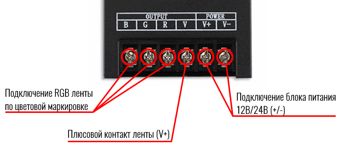
4. Input/ Output
Input: V+: positive of power input
V-: negative of power input
Output: V+: positive of output
CH1: output channel 1 (RGB: R; CT: C; DIM: CH1)
CH2: output channel 2 (RGB: G; CT: W; DIM: CH2)
CH3: output channel 3 (RGB: B; CT: -; DIM: CH3)
5. ANT
ANT: WIFI antenna
RF: touch remote control antenna
2. WiFiManager Instruction for use
1. Summarization
WiFiManager setup software is connected with controller through host USB. It mainly used to modify the network configuration of the controller, select wireless network, switch network mode, modify properties, such as the controller’s name, location, type and so on. User can flexibly choose the wireless network, modify the information of controller.
2. Instructions for use
2.1 Install WiFiManager
Remove the disc include with the controller into disc drive. Open the disc and find “WiFiManager.exe” to install software.
2.2 Use methods of WiFiManager
Open WiFiManager, it appears interface as shown below (figure 3.1): buttons of window are gray, this is because the controller is not connected. After connecting the controller through USB cable, it will appear the interface as shown in figure 3.2. Then you can operate the controller.

Figure 3.1

Figure 3.2
1. name of controllers:
the name of current connected controllers, it can be modified in the settings
2. output type of controllers:
output type of current connected controllers, select the appropriate output type according to user’s lighting type, it can be set to three output types: three-channel, two-channel, single-channel. It can be modified in the settings.
3. installation location of controllers
This option displays the installation location of controller, it can be modified
4. networking methods
Connection mode of current connected controllers
5. serial number of controllers
Serial number of current connected controller, it can not be modified.
6. searching
Search available wireless networks. The results of searching will display on the area “8”, this is all currently available networks.
7. setting
Set the parameters of controllers. (for detailed description, refer to 2.3)
8. current wireless network
Wireless networks list of currently searching
9. connecting
Connected to the currently selected network. Click “connect” to join the current network, if the network is encrypted, it will prompt you to enter your password, if it is not, it will connected to this network directly.

Figure 3.3
2. 3 Descriptions of parameters in setting page (Figure 3.3)
1. WiFi working mode
Infra: Infra network, connect with existing wireless network;
Adhoc: Ad hoc network, you do not need to connect with an external router, use mobile phone to control the controllers directly.
(Note: Currently it only supports Infra mode)
2. SSID (suitable for Adhoc mode)
Under Adhoc mode, you can set SSID, under Infra mode, it is invalid.
3. Encryption (suitable for Adhoc mode)
Open network: No security
Encrypted network: support encryption such as WEP64/WEP128/TKI/AES etc.
4. encryption password (suitable for Adhoc mode)
Set the encryption password (at least 8 characters)
5. output type
User should select corresponding output mode based on the lamps:
WF400A: full color lamps, three-channel (default);
WF400B: color temperature lamps, two-channel;
WF400C: single color lamps; single-channel.
6. set the name of controller
User can set the name of controller according to their needs (up to 32 characters), this makes the controller more humane.
7. set the location of controller
Set the location of controller (up to 32 characters). User can set specific location according to their arrangement, facilitate users to identify the location of lamps.
8. selection of WiFi channel
User can select the appropriate channel according to the needs, generally it can be set to Auto.
9. time synchronization of controller
The controller time should synchronize with computer to ensure that the timer works properly.
10. OK/ Cancel
OK: confirm the operation, the setting will take effect;
Cancel: cancel the operation, the setting will be canceled.
3. Instructions for remote control
1. on/off key 2、pause key 3、mode+ 4、mode-
5. Color pulley key 6、brightness+ 7、brightness-
8、speed+ 9、speed-
1. Key description
Touch remote panel have 64 touch button (point), each button function is as below:
1. on/off key, any state, can turn on or turn off controller output;
2. pause key, under dynamic mode, can make the controller stop current state;
3. this key have 2 function:
①mode increase key, so when the current control mode is pulley mode(color), if it need to realize the mode(color) in controller, can press this button.
②mode switch key, so when the current control mode is M key mode, can switch the regulation mode(color) in M+ key mode table.
4. This key have 2 functions:
①mode minus key, so when the current control mode is pulley mode(color), if it need to realize the mode(color) in controller, can press this button.
②mode switch key, so when the current control mode is M key mode, can switch the regulation mode(color) in M- key mode table.
5. output brightness control key, every time you press this button,the brightness series add 1, altogether 100 levels;
6. output brightness control key, every time you press this button,the brightness series minus 1, altogether 100 levels;
7. output speed control key, every time you press this button,the speed series add 1, altogether 100 levels;
8. output speed control key, every time you press this button,the speed series minus 1, altogether 100 levels;
9. Color pulley touch button, static mode choose key, up to 55 touch points.
This key have 2 functions:
①pulley static color choose button, so when the current control mode is M key mode(color), if need to realize the static color on pulley, can press this button.
②pulley color switch key: can switch from 55 static color(pulley
shows color).
2、Power management:
Stop using remote control for about 15-20s, remote control will automatically enter into standby mode, to extend the battery life for use. Color pulley touch button can not be used at this time, you must firstly click one button to wake up remote touch control, return to work station.
Note: All function of remote control is applicable to WF400A (factory default), that is RGB mode, in WF400B mode, M+, M-, B+, B- is effective, when in WF400C, only M+, M- is effective.
4. Instruction for TouchHome
1. Summarization
TouchHome is the control software that supports the use of controller, it is applicable to a single controller or multiple controllers at the same time. If has multiple controllers, user can carry out group control. The software applies to a variety of our controllers, it will load different control page depending on different controllers to adapt different controllers, facilitate user to operate. The software has features such as timer control, self-defined colors and so on dependingon different controllers, for detailed instructions, please refer to the software manual.
2. Instruction for use
2.1 Install TouchHome
Firstly make sure that you have already installed iTunes, if you have not installed, please download the lastest version of iTunes, after installation is complete, search “TouchHome” in application, install the software to your mobile phone or ipad.
2.2 Connect WiFi network
Firstly using WiFiManager software, connect all the controllers to user’s wireless network, then connect the mobile phone with “TouchHome” to the wireless network, search equipments, add the equipments into control list, then you can control the controllers. for detailed instructions, please refer to the software manual.
2.3 Summary
WF400A mode:
The mode is suitable for RGB strip, it can carry out mode switch, brightness and speed adjustment, self-defined colors and other functions. When there are multiple controllers, user can also carry out group control.
WF400B mode:
The mode is suitable for color temperature strip, it can carry out mode switch, brightness and color temperature adjustment. When there are multiple controllers, user can carry out group control, as well as timer control.
WF400C mode:
The mode is suitable for single color strip, it can carry out mode switch, brightness adjustment. When there are multiple controllers, user can carry out group control, as well as timer control.
5. Mode description of controller
When you select a different mode, the output mode of controller is different, the working mode should be configured according to the type of strip. When using RGB strip, user should select working mode as WF400A; when using color temperature strip, should select WF400B; when using single color strip, should select WF400C. Specific mode table is as follow:
1. WF400A mode:
WF400A mode: When using RGB strip, user should select this mode. It can control all four-wire loop (common anode) LED full-color lighting products, extensive control: all limiting resistor LED lighting products such as: LED module of RGB full-color, LED light strip, SMD soft strips etc. In this mode, the controller can achieve dynamic changing such as: overall jumpy changing, gradually changing, stroboflash. With the phone control software, it can carry out self-defined color changes. Under jumpy changing and stroboflash mode, you can adjust brightness and speed, under gradually changing mode, you can only adjust speed, under static mode, you can only adjust brightness. The default mode table of controller is as below:
|
No. |
Function |
Remark |
No. |
Function |
Remark |
|
1 |
Static red |
Brightness is adjustable,Speed is unadjustable |
12 |
Red stroboflash |
Brightness and speed is adjustable |
|
2 |
Static blue |
13 |
Blue stroboflash |
||
|
3 |
Static green |
14 |
Purple stroboflash |
||
|
4 |
Static cyan |
15 |
Green stroboflash |
||
|
5 |
Static purple |
16 |
Yellow stroboflash |
||
|
6 |
Static yellow |
17 |
Cyan stroboflash |
||
|
7 |
Static white |
18 |
White stroboflash |
||
|
8 |
Three-color jumpy changing |
Brightness and speed is adjustable |
19 |
Red blue gradual changing alternately |
Brightness is unadjustable, speed is adjustable |
|
9 |
Seven color jumpy changing |
20 |
Blue green gradual changing alternately |
||
|
10 |
Three-color gradual changing |
Brightness is unadjustable, speed is adjustable |
21 |
Green red gradual changing alternately |
|
|
11 |
Seven-color gradual changing |
22 |
Self-defined color |
2. WF400B mode:
WF400B mode: When using double channel color temperature strip, user should select this mode. In this mode, the controller can achieve overall color temperature and brightness adjustment. With the phone control software, it can carry out self-defined color temperature and brightness changes. The default mode table of controller is as below:
|
No. |
Brightness proportion |
Remark |
No. |
Brightness proportion |
Remark |
|
1 |
C:0% W:100% |
Brightness is adjustable |
12 |
C:55% W:45% |
Brightness is adjustable |
|
2 |
C:5% W:95% |
13 |
C:60% W:40% |
||
|
3 |
C:10% W:90% |
14 |
C:65% W:35% |
||
|
4 |
C:15% W:85% |
15 |
C:70% W:30% |
||
|
5 |
C:20% W:80% |
16 |
C:75% W:25% |
||
|
6 |
C:25% W:75% |
17 |
C:80% W:20% |
||
|
7 |
C:30% W:70% |
18 |
C:85% W:15% |
||
|
8 |
C:35% W:65% |
19 |
C:90% W:10% |
||
|
9 |
C:40% W:60% |
20 |
C:95% W:5% |
||
|
10 |
C:45% W:55% |
21 |
C:100% W:0% |
||
|
11 |
C:50% W:50% |
3. WF400C mode:
WF400C mode: When using single color strip, user should select this mode. In this mode, the controller can achieve overall brightness adjustment. With the phone control software, it can carry out self-defined brightness changes. The default mode table of controller is as below:
|
No. |
Brightness |
Remark |
No. |
Brightness |
Remark |
|
1 |
1% |
Brightness proportion |
12 |
55% |
Brightness proportion |
|
2 |
5% |
13 |
60% |
||
|
3 |
10% |
14 |
65% |
||
|
4 |
15% |
15 |
70% |
||
|
5 |
20% |
16 |
75% |
||
|
6 |
25% |
17 |
80% |
||
|
7 |
30% |
18 |
85% |
||
|
8 |
35% |
19 |
90% |
||
|
9 |
40% |
20 |
95% |
||
|
10 |
45% |
21 |
100% |
||
|
11 |
50% |
6. Hardware installation description
1. Install ANT
ANT’s installation drawing:
clockwise install WiFi antenna and anticlockwise take down the antenna.
2. Install power supply and LED equipment
This connector structure belong to drawer structure, the device interface of power supply and LED is together, four interface one the left side (CH3, CH2, CH1, V+)is connect led equipment,the fifth interface is connect the anode V+ of power supply, the sixth interface is connect the cathode V_ of power supply. According to the rated voltage of led lamp, we supply power to controller ,and the rated voltage of controller is DC5-24V. As follows:

3. RGB lamps connection diagram

When user’s lamp is RGB type, you need to set the controller type to WF400A through PC software, the output type is RGB, connect the lamp according to above diagram, then you can use it.
4. Color temperature lamps connection diagram

When user’s lamp is CW type, you need to set the controller type to WF400B through PC software, the output type is CW, connect the lamp according to above diagram, then you can use it. You can select built-in color temperature proportion of controller through the Function button on the controller or M+, M- button on the touch remote control, also can adjust overall brightness through B+, B- on the remote control or control through mobile phone software.
5. Single color lamps connection diagram

When user’s lamp is single color type, you need to set the controller type to WF400C through PC software, the output type is DIM, connect the lamp according to above diagram, then you can use it. You can select built-in brightness of controller through the Function button on the controller or M+, M- button on the touch remote control or realize dimming steplessly through mobile phone software.
IV. System Application Diagram
When there are multiple controllers in user’s wireless network, the system structure is as shown in figure 8.1. User can control these controllers separately or in group. In a control system, it can accommodate up to more than 250 controllers, about control mode, please refer to “TouchHome” software instructions.

Figure 8.1
V. Notice
1. Please don’t install controller in a seal off , high magnetic field or high pressure area;
2. In order to reduce the risk of fire disaster and device damage caused by short circuit , please make sure correct connection;.
3. Please do install controller in a well-ventilated area to insure appropriate temperature .
4. Installation position of controller should be as near as possible to the router so as to ensure controller normal working ;
5. Check out whether the supply voltage and power is in the range of controller required or not .
6. Before power on , please inspect the line is correct connection, and test it whether there is a short circuit ;
7. Any problem , please do not open the shell of controller .
8. This manual is only applicable to this model of controller, if there is an update without notice.
VI. Fault Analysis
|
No. |
Phenomenon |
Reason |
Solutions |
|
1 |
Load has no output |
1. out of power 2. output is overload 3. mistakenly connection |
1. check the power 2. increase power amplifier 3. check the connection |
|
2 |
Color is not correct |
Connection of RGB is wrong |
Check whether RGB connection is corresponding or not |
|
3 |
Indicator of remote control flicker |
The battery power is not enough |
Change battery |
|
4 |
With the voltage droping, the voltage is not uneven |
1. output cable is too long 2. output cable diameter is too small 3. controller or power supply is overload |
1. shorten the length of cable 2.use cable with large diameter 3. increase power amplifier |
VII. After-sale services
Within one year that you buy our products, if you operate correctly according to user manual, there is quality problem, we can provide free repair or replacement service, except for the following situations:
1. damage caused by misuse;
2. unauthorized disassembly, repair and modify circuit and incorrect connection;
3. damage caused by transportation, influent; damage caused due to earthquakes, fires, floods and other natural disasters.
Package inclde:
- 1 piece wifi controller
- 1 piece remote controller
- 1 piece USB cable
- 1 piece user manual