
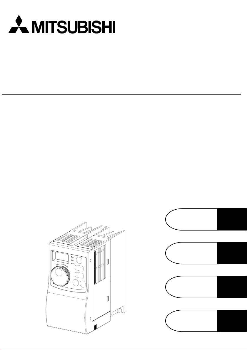
TRANSISTORIZED INVERTER
FR-S
500
IN S T R U C T IO N M A N U A L (D e ta ile d )
W IRING
Chapter 1
FUNCTIONS
PRO TECTIVE
FUNCTIONS
SPECIFICATIONS
Chapter 2
Chapter 3
Chapter 4
Thank you for choosing this Mitsubishi Transistorized inverter.
This instruction manual (detailed) provides instructions for advanced use of the
FR-S500 series inverters.
Incorrect handling might cause an unexpected fault. Before using the inverter, always
read this instruction manual and the instruction manual (basic) [IB-0600026] packed
with the product carefully to use the equipment to its optimum.
This instruction manual uses the International System of Units (SI). The measuring
units in the yard and pound system are indicated in parentheses as reference values.
This section is specifically about safety matters
Do not attempt to install, operate, maintain or inspect the inverter until you have
read through the instruction manual (basic) and appended documents carefully and
can use the equipment correctly. Do not use the inverter until you have a full
knowledge of the equipment, safety information and instructions.
In this instruction manual, the safety instruction levels are classified into
«WARNING» and «CAUTION».
WARNING
CAUTION
Note that even the CAUTION level may lead to a serious consequence according to
conditions. Please follow the instructions of both levels because they are important
to personnel safety.
1. Electric Shock Prevention
While power is on or when the inverter is running, do not open the front cover.
You may get an electric shock.
Do not run the inverter with the front cover removed. Otherwise, you may access
the exposed high-voltage terminals or the charging part of the circuitry and get
an electric shock.
If power is off, do not remove the front cover except for wiring or periodic
inspection. You may access the charged inverter circuits and get an electric
shock.
Before starting wiring or inspection, check for residual voltages with a meter etc.
more than 10 minutes after power-off.
Earth the inverter.
Any person who is involved in wiring or inspection of this equipment should be
fully competent to do the work.
Always install the inverter before wiring. Otherwise, you may get an electric
shock or be injured.
Perform setting dial and key operations with dry hands to prevent an electric shock.
Do not subject the cables to scratches, excessive stress, heavy loads or
pinching. Otherwise, you may get an electric shock.
Do not change the cooling fan while power is on.
It is dangerous to change the cooling fan while power is on.
When you have removed the front cover, do not touch the connector above the
3-digit monitor LED display. You will get an electric shock.
Assumes that incorrect handling may cause hazardous
conditions, resulting in death or severe injury.
Assumes that incorrect handling may cause hazardous
conditions, resulting in medium or slight injury, or may
cause physical damage only.
WARNING
A-1
2. Fire Prevention
CAUTION
Mount the inverter to incombustible material. Mounting it to or near combustible
material can cause a fire.
If the inverter has become faulty, switch off the inverter power. A continuous flow
of large current could cause a fire.
Do not connect a resistor directly to the DC terminals P(+), N(−). This could
cause a fire.
3. Injury Prevention
Apply only the voltage specified in the instruction manual to each terminal to
prevent damage etc.
Ensure that the cables are connected to the correct terminals. Otherwise,
damage etc. may occur.
Always make sure that polarity is correct to prevent damage etc.
While power is on and for some time after power-off, do not touch the inverter or
brake resistor as they are hot and you may get burnt.
4. Additional instructions
Also note the following points to prevent an accidental failure, injury, electric shock, etc.
(1) Transportation and installation
When carrying products, use correct lifting gear to prevent injury.
Do not stack the inverter boxes higher than the number recommended.
Ensure that installation position and material can withstand the weight of the
inverter. Install according to the information in the Instruction Manual.
Do not operate if the inverter is damaged or has parts missing.
When carrying the inverter, do not hold it by the front cover or setting dia l; it may fall off
or fail.
Do not stand or rest heavy objects on the inverter.
Check the inverter mounting orientation is correct.
Prevent screws, wire fragments, other conductive bodies, oil or other flammable
substances from entering the inverter.
Do not drop the inverter, or subject it to impact.
Use the inverter under the following environmental conditions:
Ambient
temperature
Ambient humidity 90%RH or less (non-condensing)
Storage
temperature
Ambience
Environment
Altitude, vibration
*Temperatures applicable for a short time, e.g. in transit.
-10°C to +50°C (14°F to 122°F) (non-freezing)
-20°C to +65°C * (-4°F to 149°F)
Indoors (free from corrosive gas, flammable gas,
oil mist, dust and dirt)
Maximum 1000m (3280.80feet) above sea level for
standard operation. After that derate by 3% for
every extra 500m (1640.40feet) up to 2500m
(8202.00feet) (91%).
5.9m/s
CAUTION
CAUTION
2
or less (conforming to JIS C 0040)
A-2
(2) Wiring
CAUTION
Do not fit capacitive equipment such as power factor correction capacitor, radio
noise filter or surge suppressor to the output of the inverter.
The connection orientation of the output cables U, V, W to the motor will affect
the direction of rotation of the motor.
(3) Trial run
Check all parameters, and ensure that the machine will not be damaged by a
sudden start-up.
When the load GD2 is small (at the motor GD2 or smaller) for 400V from 1.5K to
3.7K, the output current may vary when the output frequency is in the 20Hz to
30Hz range.
If this is a problem, set the Pr. 72 «PWM frecuency selection» to 6kHz or higher.
When setting the PWM to a higher frequency, check for noise or leakage current
problem and take countermeasures against it.
(4) Operation
CAUTION
WARNING
When you have chosen the retry function, stay away from the equipment as it will
restart suddenly after an alarm stop.
The [STOP] key is valid only when the appropriate function setting has been
made. Prepare an emergency stop switch separately.
Make sure that the start signal is off before resetting the inverter alarm. A failure
to do so may restart the motor suddenly.
The load used should be a three-phase induction motor only. Connection of any
other electrical equipment to the inverter output may damage the equipment.
Do not modify the equipment.
CAUTION
The electronic overcurrent protection does not guarantee protection of the motor
from overheating.
Do not use a magnetic contactor on the inverter input for frequent
starting/stopping of the inverter.
Use a noise filter to reduce the effect of electromagnetic interference. Otherwise
nearby electronic equipment may be affected.
Take measures to suppress harmonics. Otherwise power harmonics from the
inverter may heat/damage the power capacitor and generator.
When a 400V class motor is inverter-driven, it should be insulation-enhanced or
surge voltages suppressed. Surge voltages attributable to the wiring constants
may occur at the motor terminals, deteriorating the insulation of the motor.
When parameter clear or all clear is performed, each parameter returns to the
factory setting. Re-set the required parameters before starting operation.
The inverter can be easily set for high-speed operation. Before changing its
setting, fully examine the performances of the motor and machine.
In addition to the inverter’s holding function, install a holding device to ensure
safety.
Before running an inverter which had been stored for a long period, always
perform inspection and test operation.
A-3

(6) Maintenance, inspection and parts replacement
CAUTION
Do not carry out a megger (insulation resistance) test on the control circuit of the
inverter.
(7) Disposing of the inverter
CAUTION
Treat as industrial waste.
(8) General instructions
Many of the diagrams and drawings in this instruction manual show the inverter
without a cover, or partially open. Never operate the inverter like this. Always
replace the cover and follow this instruction manual when operating the inverter.
A-4

CONTENTS
1. WIRING 1
1.1 Japanese Version………………………………………………………………………….2
1.1.1 Terminal connection diagram ………………………………………………………….. 2
1.1.2 Layout and wiring of main circuit terminals……………………………………….. 3
1.2 North America Version …………………………………………………………………..4
1.2.1 Terminal connection diagram ………………………………………………………….. 4
1.2.2 Layout and wiring of main circuit terminals……………………………………….. 5
1.3 European Version………………………………………………………………………….7
1.3.1 Terminal connection diagram ………………………………………………………….. 7
1.3.2 Layout and wiring of main circuit terminals……………………………………….. 8
1.4 Description of I/O Terminal Specifications ………………………………………..9
1.4.1 Main circuit…………………………………………………………………………………….. 9
1.4.2 Control circuit …………………………………………………………………………………. 9
1.5 How to Use the Main Circuit Terminals…………………………………………..11
1.5.1 Cables, wiring lengths, crimping terminals, etc……………………………….. 11
1.5.2 Wiring instructions ………………………………………………………………………… 12
1.5.3 Peripheral devices ………………………………………………………………………… 13
1.5.4 Leakage current and installation of earth leakage circuit breaker……15
1.5.5 Power-off and magnetic contactor (MC) …………………………………………. 17
1.5.6 Regarding the installation of the power factor improving reactor ……. 18
1.5.7 Regarding noise and the installation of a noise filter…………………………18
1.5.8 Grounding precautions…………………………………………………………………..19
1.5.9 Regarding power harmoni cs…………………………………………………………… 20
1.5.10 Japanese power harmonic suppression guideline…………………………. 20
1.6 How to Use the Control Circuit Terminals……………………………………….24
1.6.1 Terminal block layout……………………………………………………………………..24
1.6.2 Wiring instructions ………………………………………………………………………… 24
1.6.3 Changing the cont rol logi c………………………………………………………………25
1.7 Input Terminals……………………………………………………………………………28
1.7.1 Run (start) and stop (STF, STR, STOP)…………………………………………. 28
1.7.2 Connectio n o f fr eq uen cy setting potentio mete r a nd output fr eq uen cy
meter (10, 2, 5, 4, AU)……………………………………………………………………31
1.7.3 External frequency selection (REX, RH, RM, RL)……………………………. 32
1.7.4 Indicator connection and adjustment……………………………………………… 34
1.7.5 Control circuit common terminals (SD, 5, SE)…………………………………. 37
1.7.6 Signal inputs by contactless switches…………………………………………….. 37
1.8 How to Use the Input Signals
(Assigned Terminals RL, RM, RH, STR)…………………………………………38
Multi-speed setting (RL, R M, R H, RE X signals): Se tting «0, 1 , 2, 8»
1.8.1
Remote setting (RL, RM, RH signals): Setting «0, 1, 2″……………………. 38
1.8.2 Second function selection (RT signal): Setting «3»……………………………38
I
Contents
1.8.3 Current input selection «AU signal»: Setting «4»………………………………..38
1.8.4 Start self-holding selection (STOP signal): Setting «5»……………………… 38
1.8.5 Output shut-off (MRS signal): Setting «6»………………………………………… 39
1.8.6 External thermal relay input: Setting «7»…………………………………………..39
1.8.7 Jog operation (JOG signal): Setting «9» ………………………………………….. 40
1.8.8 Reset signal: Setting «10»………………………………………………………………. 40
1.8.9 PID control valid terminal: Setting «14»……………………………………………. 41
1.8.10 PU operation/external operation switching: Setting «16» ………………… 41
1.9 Handling of the RS-485 Connector
(Type with RS-485 Communication Function) …………………………………41
1.10 Design Information ……………………………………………………………………. 44
2.
FUNCTIONS
2.1 Function (Parameter) List……………………………………………………………..46
2.2 List of Parameters Classified by Purpose of Use……………………………..56
2.3 Explanation of Functions (Parameters)…………………………………………..58
2.3.1 Torque boost
2.3. 2 Ma ximum an d minimu m f re q u en cy
2.3.3 Base frequency, Base frequency voltage
2.3.4 Multi-speed operation
2.3.5 Acceleration/ decel erati on time
2.3.6 Electronic overcurrent protection
2.3.7 DC injection brake
2.3.8 Starting frequency
2.3.9 Load pattern sel ection
2.3.10 Jog frequen cy
2.3.11
2.3.12 Stall prevention function and current limit function
2.3.13 Stall prevention
2.3.14 Acceleration/deceleration pattern
2.3.15 Extended fun ction displ ay selection
2.3.16 Frequency ju mp
2.3.17 Speed di splay
2.3.18 Biases and gai n s o f th e fr eq uen cy setting voltage (curre nt)
2.3.19 Start-time ground fault detection selection
2.4 Output Terminal Function Parameters……………………………………………78
2.4.1 Up-to-frequency sensitivity
2.4.2 Output frequen cy dete ction
2.5 Current Detection Function Parameters………………………………………….80
2.5.1 Output current detection functions
2.5.2 Zero current dete ction
2.6 Display Function Parameters………………………………………………………..82
2.6.1 Monitor display
RUN
key rotation direction sel e ction ……………………………………… 67
…………………………………………………………………58
………………………………… 59
…………………………………………………………………65
……………………………………………………………66
……………………………………………………………..67
to ………………………………………………………72
……………………………………………………………………..73
to ……………………………………………………………….. 74
………………………………………………………………82
…………………………………………………64
……………………………………………………69
……………………………………………………..78
……………………………………………………81
II
to
…………………………………………….64
………………………………………….71
………………………………………72
…………………………….78
…………………………………………….79
………………………………….80
………………..59
to …….61
……………….62
………………….68
45
2.6.2 Setting dial function sele ction …………………………………………………83
2.6.3 Monitoring reference
……………………………………………………..84
2.7 Restart Operation Parameters………………………………………………………84
2.7.1 Restart setting
……………………………………………………………….84
2.8 Additional Function Parameters…………………………………………………….86
2.8.1 Remote setting function selection
…………………………………………..86
2.9 Terminal Function Selection Parameters………………………………………..88
2.9.1 Input terminal fun ction sele ction
2.9.2 Output terminal function selection
…………………………………..90
……………………..88
2.10 Operation Selection Function Parameters…………………………………….91
2.10.1 Retry function
2.10.2 PWM carrier frequency
2.10.3 Applied motor
2.10.4 Voltage i npu t sele ction
………………………………………………………………………93
…………………………………………………………93
2.10.5 Input filte r time con sta nt
2.10.6 Re set se le ct io n /PU st o p se le ct io n
2.10.7 Cooling fan operation selection
2.10.8 Parameter w rite i nhib i t selectio n
2.10.9 Reverse rotati on p rev e nti on sele ctio n
2.10.10 Operation mode sele ction
2.10.11 PID cont rol
to …………………………………………………………..101
……………………………………………..91
………………………………………………..92
……………………………………………………….94
…………………………………………94
…………………………………………….96
…………………………………………..97
……………………………………98
…………………………………………………..98
2.11 Auxiliary Function Parameters …………………………………………………..109
2.11.1 Slip compensation
2.11.2 Automati c to rque b oo st sel e ction
2.11.3 Motor primary resistance
……………………………………………..109
………………………………………..109
……………………………………………………111
2.12 Calibration Parameters ……………………………………………………………. 111
2.12.1 Meter (frequency meter) calibration
2.12.2 Meter (frequency meter) calibration
(Japanese version)
(NA and EC version) …… 113
………111
2.13 Clear Parameters…………………………………………………………………….115
2.13.1 P a rameter clear
2.13.2 Alarm history clear
…………………………………………………………………115
……………………………………………………………..115
2.14 Communication Parameters
(Only for the type having the RS — 48 5 co mmun ication function)………..116
2.14.1 Communi ca tion se tti n g s
2.14.2 Operation and speed command write
2.14.3 Link start mode selectio n
2.14.4 E
2
PROM write selection ……………………………………………………..132
to , ………………………………..118
………………………….130
……………………………………………………131
2.15 Parameter Unit (FR-PU04) Setting …………………………………………….133
2.15.1 Paramete r uni t d i splay language switching
2.15.2 Buzzer sound cont rol
2.15.3 PU contrast adjust ment
…………………………………………………………133
………………………………………………………134
2.15.4 PU main display screen data selection
2.15.5 PU disconnection de te ction/PU setti ng lock
………………………….133
………………………………..134
…………………………135
Contents
III

3. PROTECTIVE FUNCTIONS 136
3.1 Errors (Alarms)………………………………………………………………………….137
3.1.1 Error (alarm) definitions………………………………………………………………..137
3.1.2 To know the operati ng sta tus at the occurren ce of alarm
(Only when FR-PU04 is used)………………………………………………………145
3.1.3 Correspondence between digital and actual characters………………….145
3.1.4 Resetting the inverter …………………………………………………………………..145
3.2 Troubleshooting…………………………………………………………………………146
3.2.1 Motor remains stopped ………………………………………………………………..146
3.2.2 Motor rotates in opposite direction ………………………………………………..147
3.2.3 Speed greatly differs from the setting…………………………………………….147
3.2.4 Acceleration/deceleration is not smooth………………………………………..147
3.2.5 Motor current is large……………………………………………………………………147
3.2.6 Speed does not increase……………………………………………………………..147
3.2.7 Speed varies during operation………………………………………………………147
3.2.8 Operation mode is not changed properly……………………………………….148
3.2.9 Operation panel di spla y is not operating………………………………………..148
3.2.10 Parameter write cannot be performed…………………………………………148
3.2.11 Motor produces annoying sound…………………………………………………148
3.3 Precautions for Maintenance and Inspection…………………………………149
3.3.1 Precautions for maintenance and inspection…………………………………. 149
3.3.2 Check items ……………………………………………………………………………….. 149
3.3.3 Periodic inspection……………………………………………………………………….149
3.3.4 Insulation resistance test using megger…………………………………………150
3.3.5 Pressure test………………………………………………………………………………. 150
3.3.6 Daily and periodic inspection……………………………………………………….. 150
3.3.7 Replacement of parts ………………………………………………………………….. 154
3.3.8 Measurement of main circuit voltages, currents and powers…………..157
4. SPECIFICATIONS 160
4.1 Specification List ……………………………………………………………………….161
4.1.1 Ratings ……………………………………………………………………………………….161
4.1.2 Common specifications………………………………………………………………..165
4.2 Outline Drawings……………………………………………………………………….167
5.
INSTRUCTIONS
5.1 Selecting Instructions …………………………………………………………………171
5.2 Peripheral Selecting Instruc tio ns………………………………………………….171
5.3 Operating Instructions ………………………………………………………………..173
5.4 Inverter-driven 400V class motor…………………………………………………175
170
APPENDIX 176
APPENDIX 1 PARAMETER DATA CODE LIST………………………………….177
IV

1. WIRING
This chapter explains the basic «wiring» for use of this
product. Always read the instructions before use.
For description of «installation», refer to the instruction
manual (basic).
1.1 Japanese Version………………………………………………2
1.2 North America Version………………………………………..4
1.3 European Version………………………………………………7
1.4 Descriptio n o f I/O Terminal specification………………..9
1.5 How to Use the Main Circuit Terminals………………..11
1.6 How to Use the Control Circuit Terminals …………….24
1.7 Input Terminals………………………………………………..28
1.8 How to Use the Input Signals
(Assigned Terminals RL, RM, RH, STR)………………38
1.9 Handling of the RS-485 Connector
(Type with RS-485 Communication Function)………. 41
1.10 Design Information………………………………………….44
<Abbreviations>
PU
Control panel and parameter unit (FR-PU04)
Inverter
Mitsubishi transistorized inverter FR-S
FR-S500
Mitsubishi transistorized inverter FR-S
Pr.
Parameter number
1
500
500
series
series
Chapter 1
1
Chapter 2
Chapter 3
Chapter 4
1
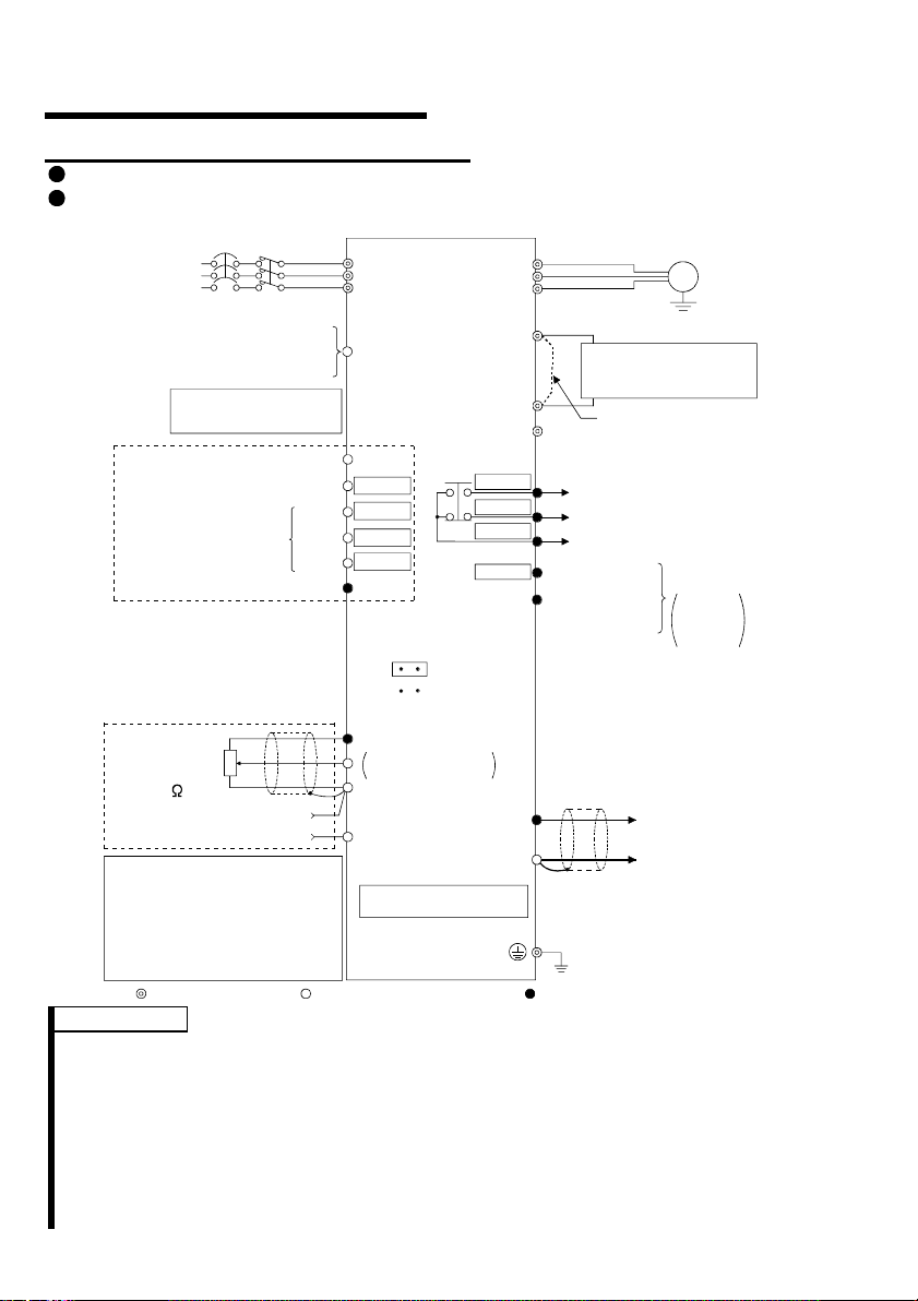
.1 Japanese Version
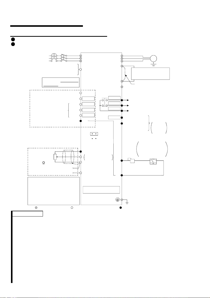
.1.1 Terminal connection diagram
1
FR-S520-0.1K to 3.7K (-R) (-C)
FR-S540-0.4K to 3.7K (-R)
MC
3-phase AC
power supply
External transistor common
Contact input common (source)
Multi-speed selection
Control input signals
(No voltage input allowe d)
Frequency setting signals (Analog)
Frequency
setting
potentiometer
1/2W1k
(*4)
When using the current input as
the frequency setting signal, set
«4» in any of Pr. 60 to Pr. 63 (input
terminal fu nction selection), assign
AU (current input selection) to any
of terminals RH, RM, RL and STR,
and turn on the AU signal.
NFB
24VDC power supply
Be careful not to short
terminals PC-SD.
Forward rotati on start
Reverse rotation start
High
Middle
Low
Contact input common
3
2
1
Current input (-)
4 to 20mADC (+)
Main circuit terminal Control circuit input t erminal Control circuit out put t erminal
Inverter
R
S
T
PC
STF
STR
*5
RH
*5
RM
*5
*5
RL
SD
(Note)
SINK
SOURCE
10 (+5V)
DC 0 to 5V
2
DC 0 to 10V
5 (Common)
4 (4 to 20mADC)
RS-485 Connector (*1)
*6
*6
*6
*6
(*3)
Selected
RUN
FM
SD
P1
SE
U
V
W
P
N
A
B
C
Power factor improving
DC reactor
(FR-BEL: Option)
Jumper:
jumper when FR-BEL
is connected.
Alarm
output
Running
Open collector
output common
Indicator
1mA full-scale
Analog meter
(Digital indicator)
1mA
Calibration
resistor (*2)
Earth (Ground)
(+) (-)
Motor
IM
Ground
Remove this
Operation status
output
Open
collector
outputs
REMARKS
*1 Only the type with RS-485 communication function.
*2 Not needed when the setting dial is used for calibration. This resistor is used
when calibration must be made near the frequency meter for such a reason as a
remote frequency meter. Note that the needle of the frequency meter may not
deflect to full-scale when the calibration resistor is connected. In this case, use
both the resistor and setting dial for calibration.
*3 You can switch between the sink and source logic positions. Refer to page 25.
*4 When the setting potentiometer is used frequently, use a 2W1kΩ potentiometer.
*5 The terminal functions change with input terminal function selection (Pr. 60 to
Pr. 63). (Refer to page 38, 88) (RES, RL, RM, RH, RT, AU, STOP, MRS, OH,
REX, JOG, X14, X16, (STR) signal selection)
*6 The terminal functions change with output terminal function selection (Pr. 64,
Pr. 65). (Refer to page 90) (RUN, SU, OL, FU, RY, Y12, Y13, FDN, FUP, RL,
LF, ABC signal selection)
2
CAUTION
To prevent a malfunct ion due to noise, keep the si gnal cables more than 10cm (3.94i nches)
away from the power cabl es.
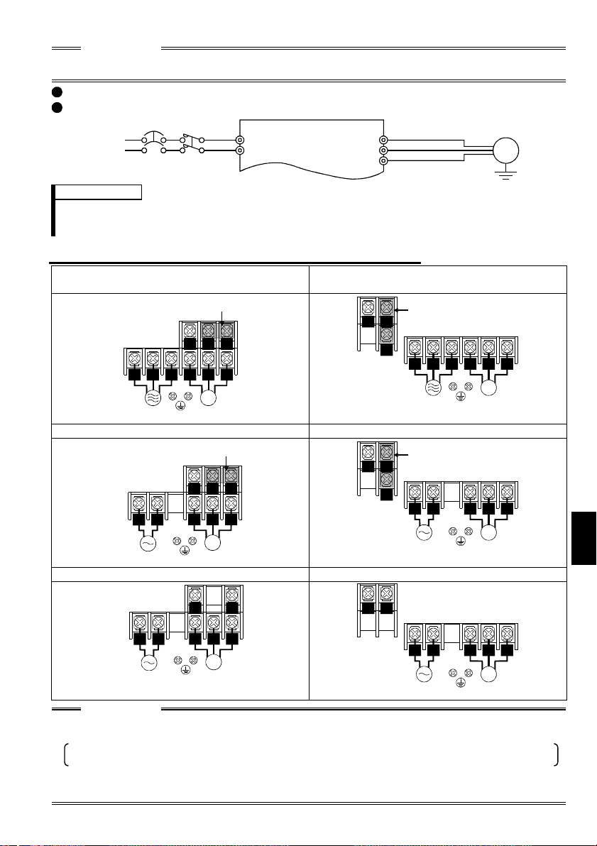
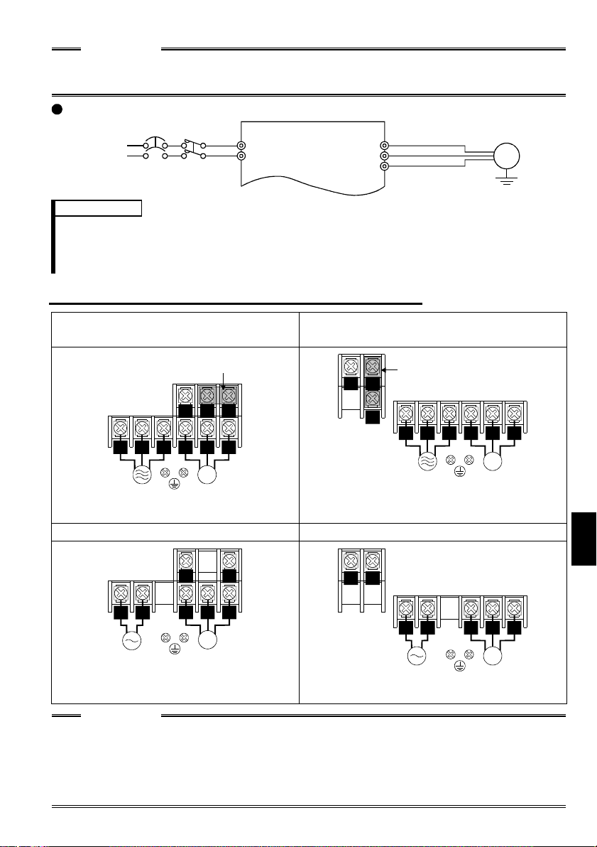
FR-S520S-0.1K to 1.5K (-R) (-C)
FR-S510W-0.1K to 0.75K (-R)
NFB
Power supply
MC
R
S
U
V
W
Motor
IM
REMARKS
To ensure safety, connect the power input to the inv erter via a magn etic contactor and earth
•
leakage circuit breaker or no-fuse breaker, and use the magnetic contactor to switch power on-off.
The output is thr ee-phase 200V.
•
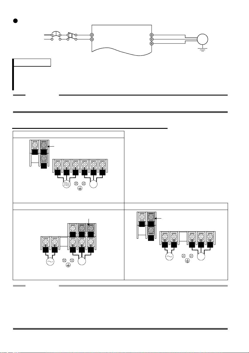
.1.2 Layout and wiring of main circuit terminals
1
FR-S520-0.1K, 0.2K, 0.4K, 0.75K (-R) (-C
Jumper
NP
P1
V
U
RST
Power supply Motor
W
IM
FR-S520-1.5K, 2.2K, 3.7K (-R) (-C)
FR-S540-0.4K, 0.75K, 1.5K, 2.2K, 3.7K (-R
NP
Jumper
P1
R S
T
Power supply Motor
U
W
V
IM
FR-S520S-0.1K, 0.2K, 0.4K, 0.75K (-R) FR-S520S-1.5K (-R)
Jumper
NP
P1
RS
Power supply Motor
V W
U
IM
N
Jumper
P
P1
RS
Power supply Motor
U V
W
IM
FR-S510W-0.1K, 0.2K, 0.4K (-R) FR-S510W-0.75K (-R)
Earth
Ground
1
NP
RS
Power supply Motor
V W
U
IM
NP
RS
Power supply
U
V
IM
Motor
W
CAUTION
The power supply cables must be connected to R, S, T. If they are connected to U, V, W,
•
the inverter will be damaged. (Phase sequence need not be mat ched.)
For use with a singl e-phase power supply, the power suppl y cables must be connected to
R and S.
Connect the motor to U, V, W.
•
Turning on the forward rotation switch (signal) at this time rotates the motor
counterclockwise when viewed from the load shaft.
3
1
.2 North America Version
.2.1 Terminal connection diagram
1
FR-S520-0.1K to 3.7K-NA
FR-S540-0.4K to 3.7K-NA (R)
NFB
3-phase A C
power supply
External transistor common
Contact input common (s our ce )
Frequency setting signals (Anal og )
When using the current input as
the frequency setting signal, set
«4» in any of Pr. 60 to Pr. 63 (input
terminal function selection), assign
AU (current input selection) to any
of terminals RH, RM, RL and STR,
and turn on the AU signal.
24VDC power supply
Take care not to short
terminals PC -SD.
Forward rotation start
Reverse rotation start
Multi-speed selection
Contact input common
Control input signals
(No voltage input allowed)
Frequency
setting
potentiometer
1/2W1k
(*3)
4 to 20mADC (+)
Main circuit terminal Control circuit input terminal
MC
3
2
1
Current input (-)
High
Middle
Low
Inverter
R
S
T
PC
STF
STR
*4
RH
*4
RM
*4
*4
RL
SD
SINK
SOURCE
10 (+5V)
DC 0 to 5V
2
DC 0 to 10V
5 (Common)
4 (4 to 20mADC)
RS-485 Connector (*1)
*5
*5
*5
*5
(*2)
Selected
U
V
W
P1
N
A
B
C
RUN
SE
AM
Power factor improving
DC reactor
(FR-BEL: Option)
P
5
Jumper:
jumper when FR-BEL
is connected.
Alarm
output
Running
Open collector
output common
(+)
(-)
Earth (Ground)
Control circuit output terminal
Motor
IM
Earth
(Ground)
Remove this
Operation status
output
Open
collector
outputs
Analog signal
output
(0 to 5VDC)
REMARKS
*1 Only the type with RS-485 communication function.
*2 You can switch between the sink and source logic positions. Refer to page 25.
*3 When the setting potentiometer is used frequently, use a 2W 1kΩ potentiometer.
*4 The terminal functions change with input terminal function selection (Pr. 60 to
Pr. 63). (Refer to page 38, 88) (RES, RL, RM, RH, RT, AU, STOP, MRS, OH,
REX, JOG, X14, X16, (STR) signal selection)
*5 The terminal functions change with output terminal function selection (Pr. 64,
Pr. 65). (Refer to page 90) (RUN, SU, OL, FU, RY, Y12, Y13, FDN, FUP, RL,
LF, ABC signal selection)
4
NOTE
To prevent a malfunction due to noise, keep the signal cables more than 10cm
(3.94inches) away from the power cables.
FR-S510W-0.1K to 0.75K-NA
NFB
Power supply
MC
R
S
U
V
W
Motor
IM
Earth
Ground
REMARKS
• To ensure safety, connect the power input to the inverter via a magnetic contactor
and earth leakage circuit breaker or no-fuse breaker, and use the magnetic
contactor to switch power on-off.
• The output is three-phase 200V.
.2.2 Layout and wiring of main circuit terminals
1
FR-S520-0.1K, 0.2K, 0.4K, 0.75K-NA
Jumper
NP
P1
RST
Power
supply
U V W
IM
Motor
FR-S520-1.5K, 2.2K, 3.7K-NA
FR-S540-0.4K, 0.75 K, 1.5K, 2. 2K, 3.7K -NA (R)
NP
Jumper
P1
R S T U V W
Power
supply
IM
Motor
FR-S510W-0.1K, 0.2K, 0.4K-NA FR-S510W-0.75K-NA
RS
Power
supply
NP
U V W
IM
Motor
NP
RS
Power
suppl
U V W
IM
Motor
CAUTION
• The power supply cables must be connected to R, S, T. If they are connected to
U, V, W, the inverter will be damaged. (Phase sequence need not be matched.)
• Connect the motor to U, V, W.
Turning on the forward rotation switch (signal) at this time rotates the motor
counterclockwise when viewed from the load shaft.
1
5
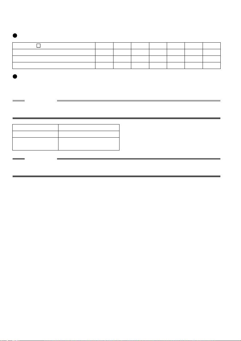
<When single-phase power input is provided for three-phase power input
inverter (NA version only)>
Reduce the output current.
FR-S520- K-NA inverter
Rated output current (A)
Power supply capacity (kVA)
AC input current (A)
0.1 0.2 0.4 0.75 1.5 2.2 3.7
0.4 0.8 1.5 2.5 4.0 5.0 7.0
0.4 0.8 1.5 2.5 4.5 5.5 9.0
1.1 2.4 4.5 6.4 11.2 12.9 17.4
Set m9 (Pr. 637) «current detection filter».
Setting «801» in the manufacturer setting parameter C8 enables you to set the m9
parameter.
CAUTION
Parameters other than m9 can also be made to be displayed, but never alter these
since they are manufacturer setting parameters.
m9 Setting Description
0 Single-phase pow er input
— — —
(Factory setting)
Three-phase power input
CAUTION
Always return the C8 parameter to 0 (factory setting) after you have finished the
setting of m9.
6
1
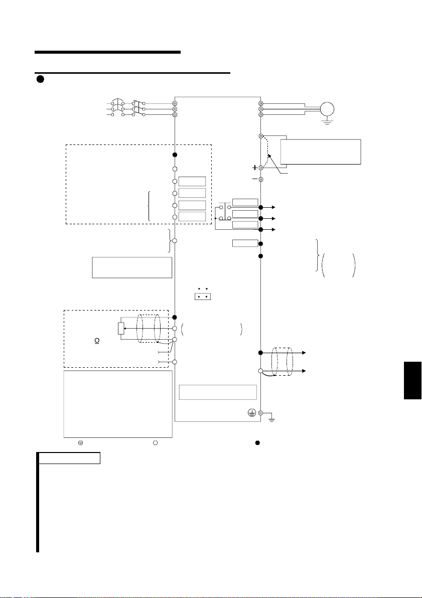
.3 European Version
.3.1 Terminal connection diagram
1
FR-S540-0.4K to 3.7K-EC(R)
MC
3-phase AC
power su pp ly
Control input signals
(No voltage input allowed)
Multi-speed selection
External transistor common
Contact input common (sink)
Frequency setting signals (Analog)
Frequency
setting
potentiometer
1/2W1k
(*3)
When using the current input as
the frequency setting signal, set
«4» in any of Pr. 60 to Pr. 63 (input
terminal function selection) , assi gn
AU (current input selection) to any
of terminals RH, RM, RL and STR,
and turn on the AU signal.
NFB
Contact input common
Forward rotation start
Reverse rotation start
High
Middle
Low
24VDC power supply
Take care not to short
terminals PC-SD.
3
2
1
Current input (-)
4 to 20mADC (+)
Main circuit terminal Control circuit input terminal
Inverter
L
1
L
2
L
3
PC
STF
STR
*4
RH *4
RM
*4
RL *4
SD
SINK
SOURCE
10 (+5V)
DC 0 to 5V
2
DC 0 to 10V
5 (Commo n)
4 (4 to 20mA DC)
RS-485 Connector (*1)
*5
*5
*5
*5
(*2)
Selected
U
V
W
P1
A
B
C
RUN
SE
AM
Power factor improving
DC reactor
(FR-BEL: Option)
Jumper
jumper when FR-BEL
is connected.
Alarm
output
Running
Open collector
output common
(+)
5
Earth (Ground)
Control circuit output terminal
(-)
Motor
IM
Earth
(Ground)
: Remove this
Operation status
output
Open
collector
outputs
Analog signal
output
(0 to 5VDC)
REMARKS
*1 Only the type with RS-485 communication function.
*2 You can switch between the sink and source logic positions. Refer to page 25.
*3 When the setting potentiometer is used frequently, use a 2W 1kΩ potentiometer.
*4 The terminal functions change with input terminal function selection (Pr. 60 to
Pr. 63). (Refer to page 38, 88) (RES, RL, RM, RH, RT, AU, STOP, MRS, OH,
REX, JOG, X14, X16, (STR) signal selection)
*5 The terminal functions change with output terminal function selection (Pr. 64,
Pr. 65). (Refer to page 90) (RUN, SU, OL, FU, RY, Y12, Y13, FDN, FUP, RL,
LF, ABC signal selection)
1
7
FR-S520S-0.2K to 1.5K-EC (R)
NFB
Power supply
MC
1
L
N
U
V
W
Motor
IM
REMARKS
• To ensure safety, connect the power input to the inverter via a magnetic
contactor and earth leakage circuit breaker or no-fuse breaker, and use the
magnetic contactor to switch power on-off.
• The output is three-phase 200V.
NOTE
• To prevent a malfunction due to noise, keep the signal cables more than 10cm
(3.94inches) away from the power cables.
.3.2 Layout and wiring of main circuit terminals
1
FR-S540-0.4K, 0.75K, 1.5K, 2.2K, 3.7K-EC (R)
Earth
(Ground)
—
Jumper
+
P1
L1 L2 L3 U V W
Power
supply
IM
Motor
FR-S520S-0.2K, 0.4K, 0.75K-EC (R) FR-S520S-1.5K-EC (R)
L1 N
Power
supply
Jumper
P1
—
U V W
IM
Motor
—
+
Jumper
+
P1
L1 N
Power
supply
CAUTION
• Connect the motor to U, V, W.
Turning on the forward rotation switch (signal) at this time rotates the motor
counterclockwise when viewed from the load shaft.
1
• For power input wiring, connect L
to R/L1 of the terminal block and N to S/L2 of
the terminal block.
• Do not connect the power supply to U, V and W.
U V W
IM
Motor
8

1
.4 Description of I/O Terminal Specifications
.4.1 Main circuit
1
Symbol Terminal Name Description
R, S, T *
1
<L
, L2, L3>
U, V, W Inverter output
N<->
P<+>, P1
* R, S <L1, N> terminals for si ngle-phase power input.
AC power input
DC voltage
common
Power factor
improving DC
reactor connection
Earth (Ground)
Connect to the commer cial power supply.
Connect a three-phase squirrel-cage motor .
DC volta
power supply and inverter output.
Disconnect the jumper from terminals P<+>-P1 and
connect the optional power factor imp rov ing DC reactor
(FR-BEL). (The single-phase 100V powe r inpu t model
cannot be connected.)
For grounding the inv erter chassis. Must be earthed.
e common terminal. Not isolated from the
CAUTION
< >Terminal names in parentheses are those of the EC version.
.4.2 Control circuit
1
Symbol Terminal Name Description
STF
STR
RH
Contact input
RM
RL
SD
(*1)
PC
(*1)
Input signals
10
2
4
Frequency setting
Forward rotation
start
Reverse rotation
start
Multi-speed
selection
Contact input
common (sink)
External
transistor
common
24VDC power
supply
Contact input
common
Frequency setting
power supply
Frequency
setting
(Voltage signal)
Frequency
setting
(Current signal)
source
Turn on the STF si
to start forward rotation
and turn it off t o stop.
Turn on the STR signal
to start reverse rotation
and turn it off t o stop.
Turn on the RH, RM and RL signals
in appropriate combinations to select
multiple speeds.
The priorities of the speed commands
are in order of jog, multi-speed setting
(RH, RM, RL, RE X ) and AU .
Common terminal for contact inputs (terminals STF, STR,
RH, RM, RL) and indicator connection (terminal FM).
Isolated from terminals 5 and SE.
When connecting the transistor output (open collector
output), such as a programmable controller (PLC),
connect the positive e xternal power supply for transistor
output to this terminal to prevent a malfunction caused by
undesirable current.
This terminal can be used as a 24V 0.1A DC power
output across t erminals PC-SD.
When source lo
contact input s ignal common.
5VDC. Permissibl e load current 10mA.
entering 0 to 5VDC (0 to 10VDC), the maximum
B
output frequency is reached at 5V (10V) and I/O are
proportional. Use Pr . 73 «0-5V/0- 10V selec tion» t o swit ch
between 5V and 10V.
Input resistance 10kΩ. Maximum permissible voltage 20V.
Enter 4-20mADC. This si
0Hz at 4mA and 60Hz at 20mA. Maximum permissible
input current 30mA. Input resistance approximately 250Ω.
For current input , turn on the signal AU.
Set the AU si
terminal function selection).
nal
When the STF and STR
signals are turned on
simultaneously, the stop
command
is given.
ic is selected, thi s terminal serves as a
nal is factory-adjusted to reac h
nal in any of Pr. 60 to Pr. 63 (input
Input terminal
function selection
(Pr. 60 to Pr. 63)
changes the
terminal functions.
(*4)
1
9

Symbol Terminal Name Description
5
Input signals
A
B
C
RUN Inverter running
Open collector
SE
Output signals
Indicator
Frequency
setting input
common
Alarm output
Open collector
output common
For meter
FM
Pulse
<Japanese>
Analog signal
AM
output
Analog
<NA, EC>
Common terminal for the frequenc
(terminals 2, 4) and indicator connection ( terminal AM).
Isolated from terminals SD and SE. Do not earth.
Change-over contact output indicating
that the output has be en stopped by the
inverter’s protective function activated.
230V 0.3A AC, 30V 0.3A DC. Alarm:
discontinuity across B-C (continuity
across A-C), normal : continuity across
B-C (discontinuit y across A-C). (*6)
Switched low when the inverter output
frequency is equal t o or higher than the
starting frequency (factory set to 0.5Hz,
variable). Switched high during stop or
DC injection brake operation. (*2)
Permissible load 24VDC 0.1A DC.
Common terminal for inverter runnin
Isolated from terminals 5 and SD.
Factory setting of output item:
One selected from
output frequency
and motor current is
output.
The output signal i s
proportional to the
magnitude of each
monitoring item.
Frequency
Permissible load current 1mA
1440 pulses/s at 60Hz
Factory setting of output item:
Frequency
Output signal 0 to 5VDC
Permissible load current 1mA
setting signals
Output
terminal
function
selection
(Pr. 64, Pr. 65)
changes the
terminal
functions. (*5)
terminal RUN.
Usin
the parameter unit connec tion c able (FR-CB201 to
−−
−−
−−−−
Communication
RS-485 connector
(*3)
205), the parameter unit (FR-PU04) is connectabl e.
Communication operation can be performed throu
RS-485.
*1. Do not connect terminals SD and PC each other or to the earth.
For sink logic, terminal SD acts as the common terminal of contact input. For
source logic, terminal PC acts as the common terminal of contact input. (Refer
to page 25 for the way to switch between them.)
*2. Low indicates that the open collector outputting transistor is on (conducts).
High indicates that the transistor is off (does not conduct).
*3. Compatible with only the type having RS-485 communication function.
(Refer to page 41.)
*4. RL, RM, RH, RT, AU, STOP, MRS, OH, REX, JOG, RES, X14, X16, (STR)
signal selection (Refer to page 88.)
*5. RUN, SU, OL, FU, RY, Y12, Y13, FDN, FUP, RL, LF, ABC signal selection
(Refer to page 90.)
*6. To be compatible with the European Directive (Low Voltage Directive), the
operating capacity of relay outputs (A, B, C) should be 30V 0.3A DC.
10
h
1
.5 How to Use the Main Circuit Terminals
.5.1 Cables, wiring lengths, crimping terminals, etc.
1
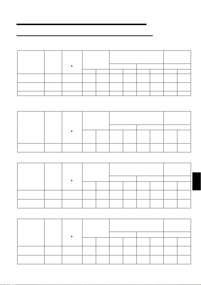
The following selection example assumes the wiring length of 20m (65.62feet).
1) FR-S520-0.1K to 3.7K (-R) (-C)
FR-S520-0.1K to 3.7K-NA
Applicable
Inverter
Model
FR-S520-0.1K
to 0.75K
FR-S520-
1.5K, 2.2K
FR-S520-3.7K
mm
Cables
2
AWG
Terminal
Screw
Size
Ti
htenin
Torque
N
Crimping
Terminals
m
R, S, T U, V, W R, S, T U, V, W R, S, T U, V, W R, S, T U, V, W
M3.5 1.2 2-3.5 2-3.5 2 2 14 14 2.5 2.5
M4 1.5 2-4 2-4 2 2 14 14 2.5 2.5
M4 1.5 5.5-4 5.5-4 3.5 3.5 12 12 4 2.5
Insulated
Cables
2) FR-S540-0.4K to 3.7K (-R)
FR-S540-0.4K to 3.7K-NA (R)
FR-S540-0.4K to 3.7K-EC (R)
Applicable
Inverter
Model
FR-S540-0.4K
to 3.7K
mm
>
Cables
2
U, V, W
R, S, T
1
, L2,
<L
3
L
>
AWG
U, V, W
Terminal
Screw
Size
Ti
htenin
Torque
N
m
Crimping
Terminals
R, S, T
1
<L
, L2,
3
L
>
U, V, W
R, S, T
1
, L2,
<L
3
L
M4 1.5 2-4 2-4 2 2 14 14 2.5 2.5
Insulated
Cables
R, S, T
1
, L2,
<L
3
L
>
3) FR-S520S-0.1K to 1.5K (-R)
FR-S520S-0.2K to 1.5K-EC (R)
Applicable
Inverter
Model
FR-S520S-
0.1K to 0.75K
FR-S520S-
1.5K
mm
Cables
2
U, V, W
AWG
R, S
<L1, N>
U, V, W
Terminal
Screw
Size
Ti
htenin
Torque
N
m
Crimping
Terminals
R, S
1
<L
, N>
U, V, W
R, S
<L1, N>
M3.5 1.2 2-3.5 2-3.5 2 2 14 14 2.5 2.5
M4 1.5 2-4 2-4 2 2 14 14 2.5 2.5
Insulated
Cables
R, S
<L1, N>
4) FR-S510W-0.1K to 0.75K (-R)
FR-S510W-0.1K to 0.75K-NA
Applicable
Inverter
Model
FR-S510W-
0.1K to 0.4K
FR-S510W-
0.75K
mm
Cables
2
AWG
Terminal
Screw
Size
Ti
htenin
Torque
N
Crimping
Terminals
m
R, S U, V, W R, S U, V, W R, S U, V, W
M3.5 1.2 2-3.5 2-3.5 2 2 14 14 2.5 2.5
M4 1.5 5.5-4 2-4 3.5 2 12 14 4 2.5
Insulated
Cables
R, S
1
, N>
<L
PVC
mm
PVC
mm
PVC
mm
PVC
mm
2
2
U, V, W
2
1
U, V, W
2
U, V, W
11

Wiring length
100m (328.08feet) maximum. (50m (164.04feet) maximum for the FR-S540-0.4K.)
CAUTION
• When the wiring length of the 0.1K or 0.2K is 30m (98.43feet) or more, use the
carrier frequency to 1kHz.
• Use the carrier frequency of 1kHz when the wiring length of the FR-S540-0.4K,
0.75K is 30m (98.43feet) or more.
• The wiring length should be 30m (98.43feet) maximum when automatic torque
boost is selected in Pr. 98 «automatic torque boost selection (motor capacity)».
(Refer to page 109)
.5.2 Wiring instructions
1
1) Use insulation-sleeved crimping terminals for the power supply and motor cables.
2) Application of power to the output terminals (U, V, W) of the inverter will damage
the inverter. Never perform such wiring.
3) After wiring, wire off-cuts must not be left in the inverter.
Wire off-cuts can cause an alarm, failure or malfunction. Always keep the inverter
clean.
When drilling a control box etc., take care not to let wire off-cuts enter the inverter.
4) Use cables of the recommended size to make a voltage drop 2% maximum.
If the wiring distance is long between the inverter and motor, a main circuit cable
voltage drop will cause the motor torque to decrease especially at the output of a
low frequency.
5) For long distance wiring, the fast-response current limit function may be reduced or
the devices connected to the secondary side may malfunction or become faulty
under the influence of a charging current due to the stray capacity of wiring.
Therefore, note the maximum overall wiring length.
6) Electromagnetic wave interference
The input/output (main circuit) of the inverter includes harmonic components, which
may interfere with the communication devices (such as AM radios) used near the
inverter. In this case, install the optional FR-BIF radio noise filter (for use in the
input side only) or FR-BSF01 or FR-BLF line noise filter to minimize interference.
7) Do not install a power capacitor, surge suppressor or radio noise filter (FR-BIF
option) in the output side of the inverter.
This will cause the inverter to trip or the capacitor and surge suppressor to be
damaged. If any of the above devices are connected, remove them. (When using
the FR-BIF radio noise filter with a single-phase power supply, connect it to the
input side of the inverter after isolating the T <L
 Before starting rewiring or other work after performing operation once, check the
voltage with a meter etc. more than 10 minutes after power-off. For some time after
power-off, there is a dangerous voltage in the capacitor.
12
3
> phase securely.)
.5.3 Peripheral devices
1
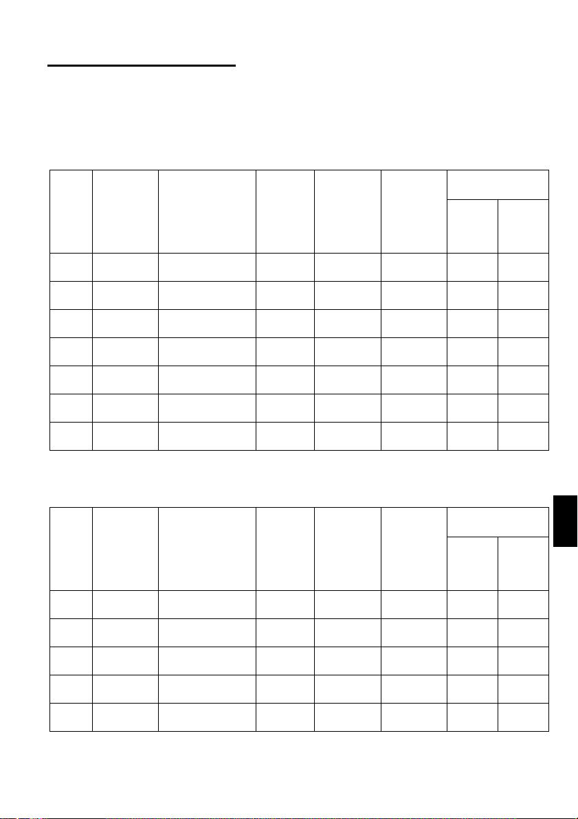
(1) Selection of peripheral devices
Check the capacity of the motor applicable to the inverter you purchased. Appropriate
peripheral devices must be selected according to the capacity.
Refer to the following list and prepare appropriate peripheral devices:
1) FR-S520-0.1K to 3.7K (-R) (-C)
FR-S520-0.1K to 3.7K-NA
Motor
Output
(kW
(HP))
0.1
(1/8)
0.2
(1/4)
0.4
(1/2)
0.75
(1)
1.5
(2)
2.2
(3)
3.7
(5)
Inverter
Model
FR-S520-
0.1K
FR-S520-
0.2K
FR-S520-
0.4K
FR-S520-
0.75K
FR-S520-
1.5K
FR-S520-
2.2K
FR-S520-
3.7K
Rated current of
Circuit Breaker
(Refer to
page 15)
(*1)
30AF/5A S-N10
30AF/5A S-N10
30AF/5A S-N10 FR-BAL-0.4K FR-BEL-0.4K 2 2
30AF/10A S-N10
30AF/15A S-N10 FR-BAL-1.5K FR-BEL-1.5K 2 2
30AF/20A
30AF/30A S-N20 FR-BAL- 3.7KFR-BAL-3. 7K 3.5 3.5
Magnetic
Contactor
(MC)
(Refer to
page 17)
S-N11,
S-N12
Power
Factor
Improving
AC Reactor
(Refer to
page 18)
FR-BAL-0.4K
(*3)
FR-BAL-0.4K
(*3)
FR-BAL-
0.75K
FR-BAL-2.2K FR-BEL-2.2K 2 2
Power
Factor
Improving
DC Reactor
(Refer to
page 18)
FR-BEL-0.4K
(*3)
FR-BEL-0.4K
(*3)
FR-BEL-
0.75K
Cables (mm2)
(*2)
R, S, T U, V, W
22
22
22
2) FR-S540-0.4K to 3.7K (-R)
FR-S540-0.4K to 3.7K-NA (R)
FR-S540-0.4K to 3.7K-EC (R)
Motor
Output
(kW
(HP))
0.4
(1/2)
0.75
(1)
1.5
(2)
2.2
(3)
3.7
(5)
Inverter
Model
FR-S540-
0.4K
FR-S540-
0.75K
FR-S540-
1.5K
FR-S540-
2.2K
FR-S540-
3.7K
Rated current of
Circuit Breaker
(Refer to
page 15)
(*1)
30AF/5A S-N10
30AF/5A S-N10
30AF/10A S-N10
30AF/15A S-N20
30AF/20A S-N20
Magnetic
Contactor
(MC)
(Refer to
page 17)
13
Power
Factor
Improving
AC Reactor
(Refer to
page 18)
FR-BAL-
H0.4K
FR-BAL-
H0.75K
FR-BAL-
H1.5K
FR-BAL-
H2.2K
FR-BAL-
H3.7K
Power
Factor
Improving
DC Reactor
(Refer to
page 18)
FR-BEL-
H0.4K
FR-BEL-
H0.75K
FR-BEL-
H1.5K
FR-BEL-
H2.2K
FR-BAL-
H3.7K
Cables (mm2)
(*2)
R, S, T
1
<L
, L2,
U, V, W
3
>
L
22
22
22
22
22
1

3) FR-S520S-0.1K to 1.5K (-R)
FR-S520S-0.2K to 1.5K-EC (R)
Power
Factor
Improving
DC Reactor
(Refer to
page 18)
(*3)
FR-BEL-
0.75K
Cables (mm2)
R, S
1
<L
22
Motor
Output
(kW
(HP))
0.1
(1/8)
0.2
(1/4)
0.4
(1/2)
0.75
(1)
1.5
(2)
Inverter
Model
FR-S520S-
0.1K
FR-S520S-
0.2K
FR-S520S-
0.4K
FR-S520S-
0.75K
FR-S520S-
1.5K
Power
Rated current of
Circuit Breaker
(Refer to
page 15)
(*1)
30AF/5A S-N10 FR-BAL-0.4K FR-BEL-0.4K 2 2
30AF/10A S-N10 FR-BAL-0.4K FR-BEL-0.4K 2 2
30AF/10A S-N20
30AF/15A S-N20 FR-BAL-1.5K FR-BEL-1.5K 2 2
30AF/20A S-N21 FR-BAL-2.2K FR-BEL-2.2K 2 2
Magnetic
Contactor
(MC)
(Refer to
page 17)
Factor
Improving
AC Reactor
(Refer to
page 18)
(*3)
FR-BAL-
0.75K
4) FR-S510W-0.1K to 0.75K (-R)
FR-S510W-0.1K to 0.75K-NA
Power
Factor
Improving
DC Reactor
(Refer to
page 18)
(*4)
−−
−−
−−−−
−−
−−
−−−−
−−
−−
−−−−
−−
−−
−−−−
Cables (mm2)
R, S
1
<L
22
22
22
3.5 2
Motor
Output
(kW
(HP))
0.1
(1/8)
0.2
(1/4)
0.4
(1/2)
0.75
(1)
Inverter
Model
FR-S510W-
0.1K
FR-S510W-
0.2K
FR-S510W-
0.4K
FR-S510W-
0.75K
Power
Rated current of
Circuit Breaker
(Refer to
page 15)
(*1)
30AF/10A S-N10
30AF/15A S-N10 FR-BAL- 1.5K
30AF/20A S-N20 FR-BAL- 2.2K
30AF/30A S-N20 FR-BAL- 3.7K
Magnetic
Contactor
(MC)
(Refer to
page 17)
Factor
Improving
AC Reactor
(Refer to
page 18)
FR-BAL-
(*3)
0.75K
*1 For installations in the United States or Canada, the circuit breaker must be
inverse time or instantaneous trip type.
*2 The size of the cables assume that the wiring length is 20m (65.62feet).
*3 The power factor may be slightly less.
*4 The single-phase 100V power input model does not allow the power factor
improving DC reactor to be fitted.
, N>
, N>
(*2)
U, V, W
(*2)
U, V, W
14
.5.4 Leakage current and installation of eart h leakag e ci r cui t br eaker
1
Due to static capacitances existing in the inverter I/O wiring and motor, leakage
currents flow through them. Since their values depend on the static capacitances,
carrier frequency, etc., take the following counter measures.
(1) To-ground leakage currents
Leakage currents may flow not only into the inverter’s own line but also into the
other line through the ground cable, etc.
These leakage currents may operate earth leakage circuit breakers and earth
leakage relays unnecessarily.
Counter measures
If the carrier frequency setting is high, decrease the carrier frequency (Pr. 72) of
the inverter.
Note that motor noise increases. Selection of Soft-PWM control (Pr. 70) will make
it unoffending. (Factory setting)
By using earth leakage circuit breakers designed for harmonic and surge
suppression (e.g. Mitsubishi’s Progressive Super Series) in the inverter’s own line
and other line, operation can be performed with the carrier frequency kept high
(with low noise).
(2) Line-to-line leakage currents
Harmonics of leakage
currents flowing in static
capacities between the
inverter output cables
may operate the external
thermal relay
unnecessarily.
Counter measures
Use the electronic overcurrent protection of the inverter.
Decrease the carrier frequency. Note that motor noise increases. Selection of
Soft-PWM (Pr. 70) makes it unoffending.
To ensure that the motor is protected against line-to-line leakage currents, it is
recommended to use a temperature sensor to directly detect motor temperature.
Installation and selection of no-fuse breaker
On the power receiving side, install a no-fuse breaker (NFB) to protect the primary
wiring of the inverter. Which NFB to choose depends on the power supply side
power factor (which changes with the power supply voltage, output frequency and
load) of the inverter. Especially as the completely electromagnetic type NFB
changes in operational characteristic with harmonic currents, you need to choose
the one of a little larger capacity. (Check the data of the corresponding breaker.)
For the earth leakage circuit breaker, use our product designed for harmonic and
surge suppression (Progressive Super Series). (Refer to page 13 for the
recommended models.)
Power
supply
NFB
Inverter
Line-to-Line Leakage Current Path
Thermal relay
Line static
capacitances
Motor
IM
1
CAUTION
Choose the NFB type according to the power supply capacity.
15
(3) Selecting the rated sensitivity current for the earth leakage circuit
breaker
When using the earth leakage circuit breaker with the inverter circuit, select its rated
sensitivity current as follows, independently of the PWM carrier frequency:
Progressive Super Series
(Type SP, CF, SF, CP)
Rated sensitivity current:
I∆n ≥ 10 × (lg1+Ign+lg2+lgm)
Conventional NV series (Type CA,
CS, SS produced prior to ’91)
Rated sensitivity current:
I∆n ≥ 10 × {lg1+lgn+3 × (lg2+lgm)}
lg1, lg2 : Leakage currents of cable
path during commercial
power supply operation
lgn* : Leakage current of noise
filter on inverter input side
lgm : Leakage current of motor
during commercial power
supply operation
<Example>
2mm ×5m
(16.40feet)
NV
Ig1 Ign Ig2 Igm
CAUTION
• The earth leakage circuit breaker should be installed to the primary (power
supply) side of the inverter.
• In the
connection neutral point grounded system, the sensitivity current
becomes worse for ground faults in the inverter secondary side. Hence, the
protective grounding of the load equipment should be 10Ω or less.
• When the breaker is installed in the secondary side of the inverter, it may be
unnecessar ily oper at ed by har m onics if the effe ct ive v alu e i s le ss than the rat ing. In th is
case, do not insta ll the brea ker since th e eddy curre nt and hy steresis loss in crease and
the temperature rises.
* Note the leakage current value of the noise filter installed on the inverter input
side.
Progressive Super Series
Leakage current (Ig1) (mA)
Leakage current (Ign) (mA
Leakage current (Ig2) (mA)
Motor leakage
current (Igm) (mA)
Total leakage current (mA)
Rated sensitivity current
≥≥≥≥
(mA) (
Ig
××××
10)
Example of leakage
current per 1km in cable
path during commercial
power supply operation
when the CV cable is
routed in metal conduit
(200V 60Hz)
120
100
80
60
40
20
0
23.5 814223880
Leakage current (mA)
22
2mm ×70m
5.5 30 60100
Cable size (mm )
(229.66feet)
Noise
filter
Inverter
IM
3
200V
1.5kW
(2HP)
(Type SP, CF, SF,CP)
20
5m (16.40feet)
×
1000m
3280.80feet
0 (without noise filter)
70m (229.66feet)
20
×
1000m
3280.80feet
0.14
1.66 4.78
30 100
Leakage current
example of 3-phase
induction motor
during commercial
power supply
operation
(200V 60Hz)
2.0
1.0
0.7
0.5
0.3
0.2
150
2
0.1
Leakage current (mA)
Motor capacity (kW
Conventional NV
(Type CA, CS, SS)
1.5
2.2
= 0.10
= 1.40
7.515221137
3.7
5.5 18.5
55
45
30
16
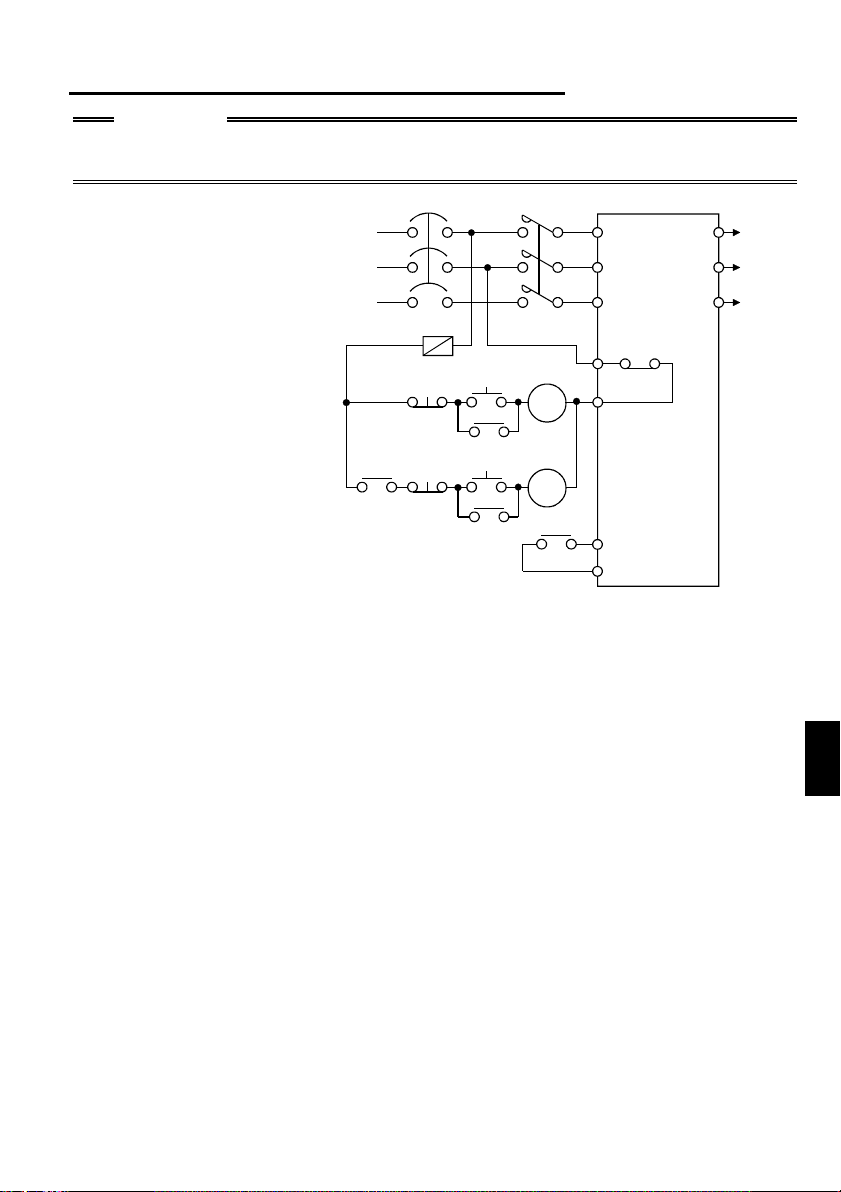
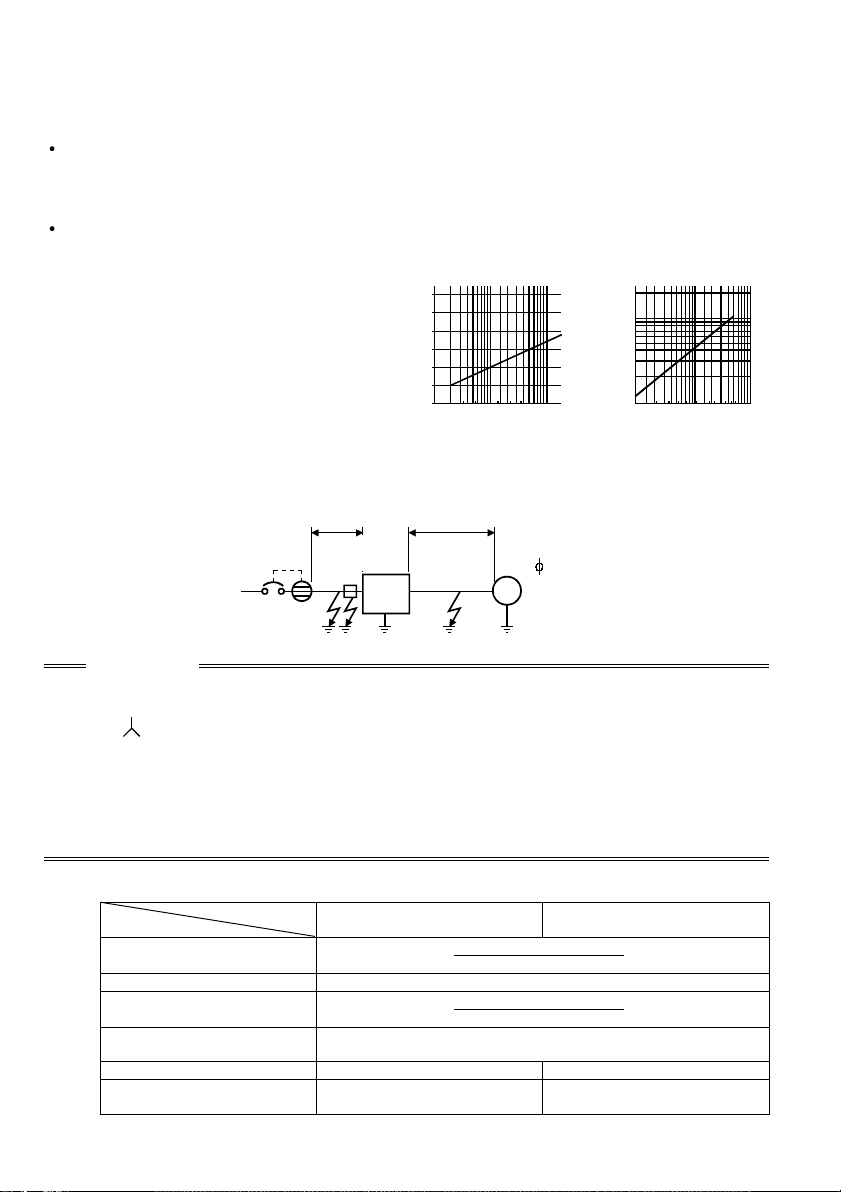
.5.5 Power-off and magnetic contactor (MC)
1
CAUTION
Do not use the inverter power supply side magnetic contactor to start or stop the
inverter.
As shown on the right,
always use the start signal
(ON or OFF across
terminals STF or STR-SD)
to make a start or stop.
(Refer to page 28)
NFB
Power
supply
F
OFF
MC
OFF
ON
MC
ON
RA
MC
MC
RA
RA
R<L
>
1
S<N>
T
B
OFF
C
Inverter
STF (STR)
SD
W
U
To
V
moto
Inverter Start/Stop Circuit Example
(1) Inverter’s primary side magnetic contactor (MC)
On the inverter’s primary side, it is recommended to provide an MC for the following
purposes (Refer to page 13 for selection.):
1) To release the inverter from the power supply when the inverter’s protective
function is activated or when the drive is not functioning (e.g. emergency stop
operation).
2) To prevent an accident caused by an automatic restart made at power restoration
after an inverter stop due to a power failure.
3) To rest the inverter for a long time.
The control power supply for inverter is always running and consumes a little
power. When stopping the inverter for a long time, switching inverter power off
saves power slightly.
4) To separate the inverter from the power supply to ensure safety of
maintenance/inspection work.
As the inverter’s primary MC is used for the above purposes, it is equivalent to the
standard duty and select the one of class JEM1038-AC3 for the inverter input side
current.
1
17
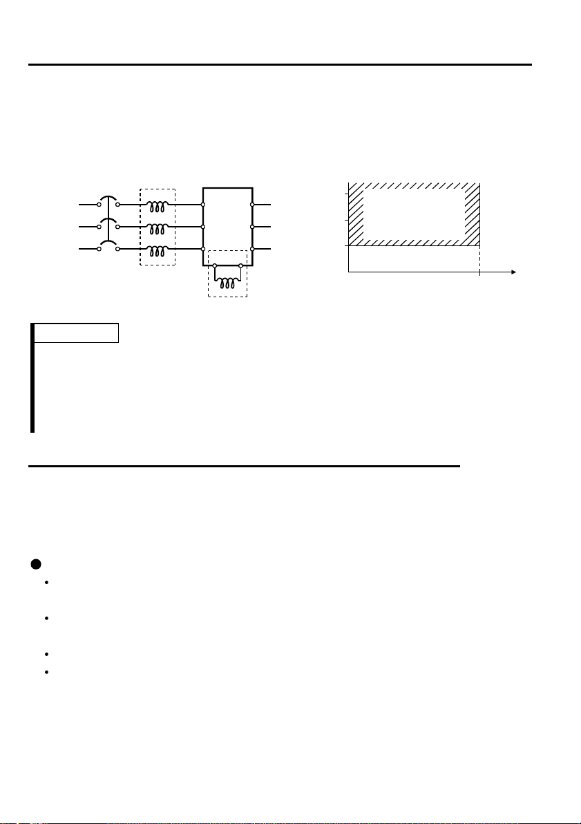
5.6 Regarding the installation of the power factor improvi ng reactor
1.
When the inverter is installed near a large-capacity power transformer (500kVA or
more at the wiring length of 10m (32.81feet) or less) or the power capacitor is to be
switched, an excessive peak current will flow in the power supply input circuit,
damaging the converter circuit. In such a case, always install the power factor
improving reactor (FR-BEL or FR-BAL).
Power
supply
FR-BAL
NFB
R
S
TZ
X
Y
Inverter
R<L
>
1
U
S<N>
V
W
T
P<+>P1
FR-BEL(*)
Power supply equipment
1500
1000
500
capacity (kVA)
Power factor
improving reactor
installation range
010
Wiring length (m)
REMARKS
* When connecting the FR-BEL, remove the jumper across terminals P<+>-P1.
The wiring length between FR-BEL and inverter should be 5m (16.40feet)
maximum and as short as possible.
Use the cables which are equal in size to those of the main circuit. (Refer to page
11)
.5.7 Regarding noise and the installation of a noise filter
1
Some noise enters the inverter causing it to malfunction and others are generated by
the inverter causing the malfunction of peripheral devices. Though the inverter is
designed to be insusceptible to noise, it handles low-level signals, so it requires the
following general counter measures to be taken.
General counter measures
Do not run the power cables (I/O cables) and signal cables of the inverter in
parallel with each other and do not bundle them.
Use twisted shield cables for the detector connecting and control signal cables
and connect the sheathes of the shield cables to terminal SD.
Ground the inverter, motor, etc. at one point.
Capacitances exist between the inverter’s I/O wiring, other cables, earth and
motor, through which leakage currents flow to cause the earth leakage circuit
breaker, earth leakage relay and external thermal relay to operate unnecessarily.
To prevent this, take appropriate measures, e.g. set the carrier frequency in Pr. 72
to a low value, use an earth leakage circuit breaker designed for suppression of
harmonics and surges, and use the electronic overcurrent protection built in the
inverter.
18
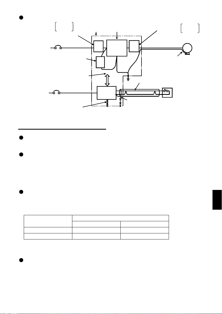
Noise reduction examples
Install filter
on inverter’s input side.
Inverter
power su pply
Separate inverte r and power
line more than 30cm (3.94inches)
(at least 10cm (11.81inches))
from sensor circuit.
Control
power su pply
.5.8 Grounding precautions
1
FR-BLF
FR-BSF01
Install filter FR — BIF
on inverter’s input side.
Do not earth control
box directly.
Do not earth
control cable.
Control
box
FR-
BLF
FRBIF
Power
supply
for sensor
Reduce carrier
frequency.
Inverter
FRBLF
Use twisted pair shielded cable.
Do not earth shield but connect
it to signal common cable.
Install filter
on inv erter’s output si d e.
Use 4-core cable for motor
power cable and use one
cable as earth cable.
Sensor
FR-BLF
FR-BSF01
MotorIM
Leakage currents flow in the inverter. To prevent an electric shock, the inverter and
motor must be grounded.
Use the dedicated ground terminal to ground the inverter. (Do not use the screw in
the casing, chassis, etc.)
Use a tinned* crimping terminal to connect the earth cable. When tightening the
screw, be careful not to break the threads.
*Plating should not include zinc.
Use the thickest possible ground cable. Use the cable whose size is equal to or
greater than that indicated in the following table, and minimize the cable length.
The grounding point should be as near as possible to the inverter.
(Unit: mm2)
Motor Capacity
2.2kW (3HP) or less 2 (2.5) 2 (2.5)
3.7kW (5HP) 3.5 (4) 2 (4)
200V, 100V class 400V class
Ground Cable Size
For use as a product compliant with the Low Voltage Directive, use PVC cable
whose size is indicated within parentheses.
Ground the motor on the inverter side using one cable of the 4-core cable.
19
1
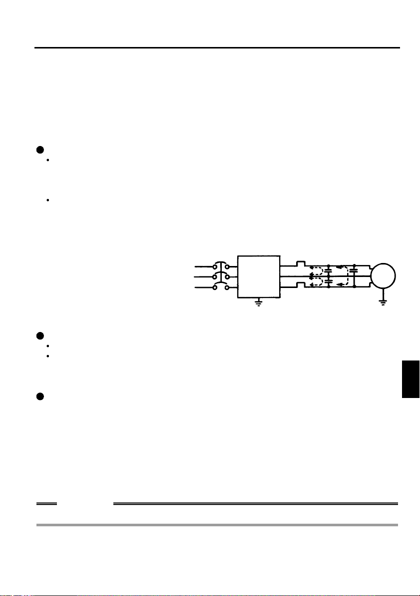
.5.9 Reg ardi ng pow er har mon ics
1
The inverter may generate power harmonics from its converter circuit to affect the
power generator, power capacitor etc. Power harmonics are different from noise and
leakage currents in source, frequency band and transmission path. Take the following
counter measure suppression techniques.
The following table indicates differences between harmonics and noise:
Item Harmonics Noise
Frequency
Environment
Quantitative
understanding
Generated amount
Affected equipment
immunity
Suppression example
Suppression technique
Harmonic currents produced
on the power supply side by
the inverter change with such
conditions as whether there
are wiring impedances and a
Normall
less (up to 3kHz or l ess)
To-electric c hannel, power
impedance
Theoretical cal culation possible
Nearly proporti onal to load
capacity
Specified in st andard per
equipment
Provide reactor. Increase distance.
40th to 50th degrees or
NFB
High frequency (several 10kHz
to MHz order)
To-space, distance, wiring path
Random occurrence, quantitative
grasping difficult
e with current variation
Chan
larger as switching speed
ratio
increases)
Different dependin
equipment specifications
Power factor
improving DC reactor
Inverter
on maker’s
Motor
IM
power factor improving
reactor and the magnitudes of
output frequency and output
current on the load side.
Power factor
improving AC reactor
Do not provide power factor
improving capacitor.
For the output frequency and output current, we understand that they should be
calculated in the conditions under the rated load at the maximum operating frequency.
CAUTION
The power factor improving capacitor and surge suppressor on the inverter output
side may be overheated or damaged by the harmonic components of the inverter
output. Also, since an excessive current flows in the inverter to activate overcurrent
protection, do not provide a capacitor and surge suppressor on the inverter output
side when the motor is driven by the inverter. To improve the power factor, insert a
power factor improving reactor in the inverter’s primary side or DC circuit. For full
information, refer to page 18.
.5.10 Japanese power harmonic suppression guideline
1
Harmonic currents flow from the inverter to a power receiving point via a power
transformer. The harmonic suppression guideline was established to protect other
consumers from these outgoing harmonics.
1) [Harmonic suppression guideline for household appliances and general-purpose
products]
The «harmonic suppression guideline for household appliances and general-purpose
products» issued by ex-Ministry of International Trade and Industry (present Ministry
of Economy, Trade and Industry) in September, 1994 applies to the FR-S500 series
other than the three-phase 400V class. By installing the FR-BEL or FR-BAL power
factor improving reactor, this product complies with the «harmonic suppression
techniques for transistorized inverters (input current 20A or less)» established by the
Japan Electrical Manufacturers’ Association.
20
2) «Harmonic suppression guideline for specific consumers»
This guideline sets forth the maximum values of harmonic currents outgoing from a
high-voltage or specially high-voltage consumer who will install, add or renew
harmonic generating equipment. If any of the maximum values is exceeded, this
guideline requires that consumer to take certain suppression measures.
Table 1 Maximum Values of Outgoing Harmonic Currents per 1kW Contract Power
Received Power Voltage 5th 7th 11th 13th 17th 19th 23rd
6.6kV 3.5 2.5 1.6 1.3 1.0 0.9 0.76 0.70
22 kV 1.8 1.3 0.82 0.69 0.53 0.47 0.39 0.36
33 kV 1.2 0.86 0.55 0.46 0.35 0.32 0.26 0.24
Over
23rd
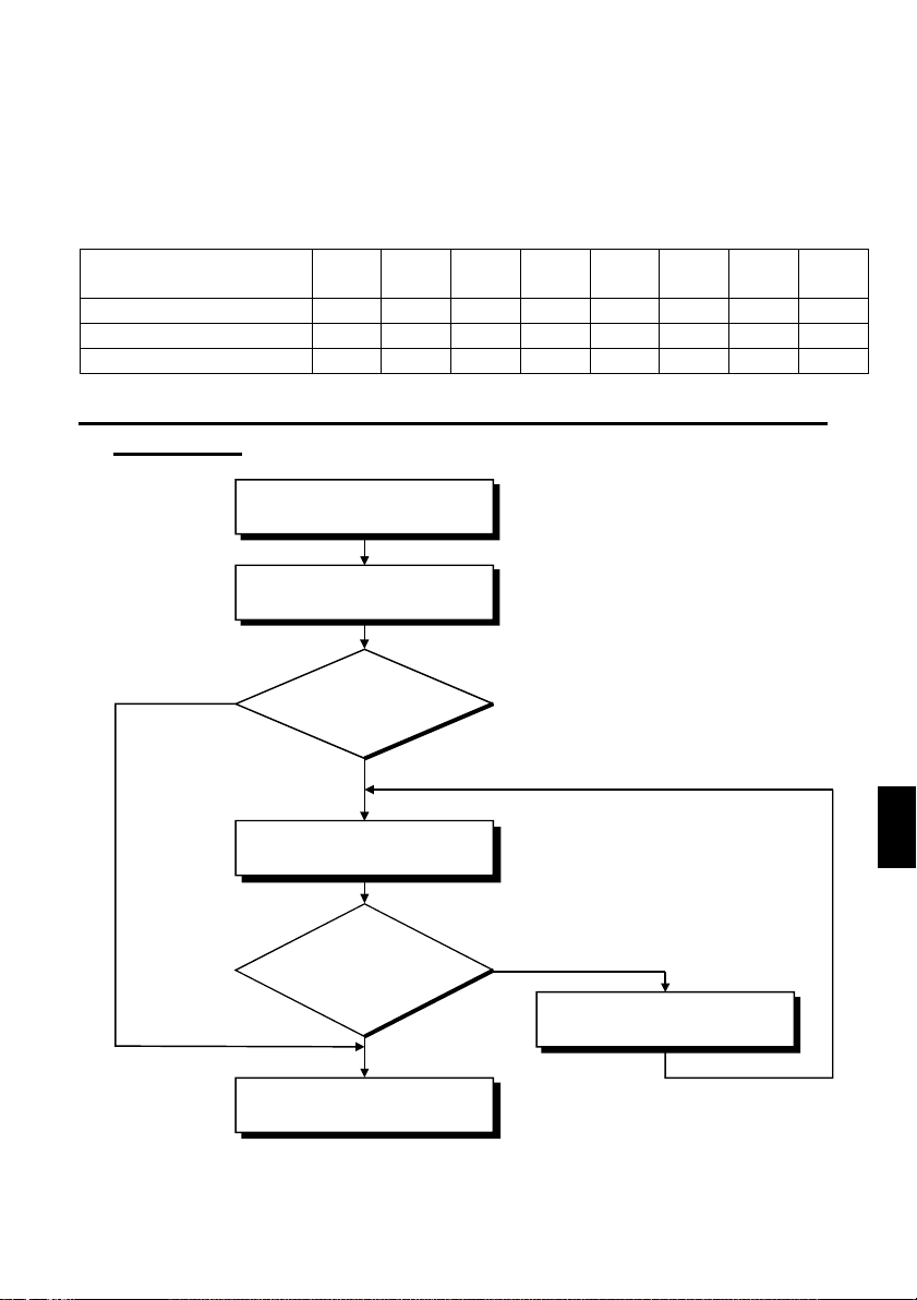
(1) Application of the harmonic suppression guideline for specific
consumers
New installation/addition/
renewal of equipment
Calculation of equivalent
capacity sum
Not more tha n
reference capacity
Sum of equivalent
capacities
Over reference
capacity
Calculation of outgoing
harmonic current
Is outgoing harmonic
current equal to or lower
than maximum value?
Not more than
maximum value
Harmonic suppression
technique is not required.
1
Over maximum value
Harmonic suppression
technique is required.
21
Loading…
Преобразователь частоты митсубиси s500

Устройства предназначены для мощности до 3,7 кВт, напряжение сети питания: 1-фазная, либо 3-фазная сеть 220, 380 вольт, 50 герц.
Технические данные
- Интервал частоты выхода от 0,5 до 120 Гц.
- Пульт встроен.
- Функционирование по интерфейсу протокола RS
- 2 входа аналоговых: 0 — 20 мА, 0 — 10 В.
- Вольт – частотный режим.
- Автоматический перезапуск.
- 15 ступеней запрограммированных скоростей.
- Регулятор встроен.
- Токовая перегрузка 200%.
Сфера использования
- Агрегаты текстильного производства.
- Конвейерные линии.
- Дробильные установки.
- Ленты транспортеров.
- Мельничные комплексы.
- Станции насосов.
- Металлообрабатывающие станки.
- Системы вентиляции.
- Оборудование полиграфии.
- Деревообработка.
Компания Mitsubishi Electric произвела пополнение серии частотников компактными устройствами FR-S500. Эта фирма является лидером в выпуске частотных преобразователей. По ее продукции устанавливаются стандарты для различных производителей. Преобразователь S500 стал мощным прорывом в обновлении типов частотников. Габариты новых приборов значительно уменьшены. Последняя серия инверторов стала наиболее компактной по сравнению с аналогичными по характеристикам моделями.
Программное обеспечение выполнено по универсальному методу, поддерживается различными преобразователями. Пользователь, который ранее сталкивался с частотниками этой фирмы, легко сможет работать с приборами серии 500, сделать его настройку для запуска и эффективной работы.
Цифровой регулятор
При разработке конструкции частотника серии s500 руководствовались принципом быстроты настройки и простоты управления. Цифровой регулятор подобен джойстику мобильника или видеомагнитофона. Внедрение регулятора цифрового типа дало возможность замены обычных кнопок. Доступ к необходимым параметрам можно получить значительно проще. Такая возможность облегчает настройку частотника новыми операторами, исключает некорректность настройки.
Тот факт, что в преобразователе имеется порт интерфейса RS 485 для серии s500 дает возможность инверторам производить обмен данных с компьютером, применяя программное управление, и с ПЛК контроллером программируемого вида. Можно соединить до 32 частотных преобразователей. При необходимости есть возможность применить один из частотников серии s500 для наружного контроля. Например, это можно сделать для копирования значений свойств настройки при применении значительного количества оборудования, на серьезных промышленных объектах. А также на пульте диспетчера для удаленного доступа. Частотный преобразователь по-настоящему стал «глобальным игроком», есть в наличии сертификат ГОСТ. Он позволяет применять различную логику во время управления.
Фирма под названием Mitsubishi Electric создала для инверторов серии s500 инновационные элементы поддержания соответствующих стандартов повышенного качества. Транзисторный модуль обеспечен системой автоподдержания момента. Это векторный аналог, позволяющий достигать 150% от момента номинала при 6 герцах частоты. Частотники этой серии оснащены интегрированной системой контроля значения тока и ограничитель на электронных элементах возрастания тока для обеспечения защиты коммутирующих элементов.
источник
Коды ошибок частотного преобразователя Mitsubishi

Частотные преобразователи относятся к сложной промышленной электронике достаточно дорогой и в тоже время широко распространенной по всему миру. На сегодняшний день трудно себе даже представить какое-либо производство, на котором бы не работало данное промышленное оборудование.
К сожалению, в процессе эксплуатации выходит из строя даже самое надежное промышленное оборудование. В данной статье мы разберем частотный преобразователь Mitsubishi, точнее коды ошибок частотного преобразователя Mitsubishi 700-ой серии (FR-D720S, FR-D720SC, FR-D720EC, FR-D740S, FR-D740SC, FR-D740EC), с полной расшифровкой. Частотники в наше время нашли широкое применения в абсолютно всех сферах промышленности управляя как мини моторами в оргтехнике, так и гигантскими двигателями в горнодобывающей промышленности.
Для простоты общения со столь сложной электроникой все частотные преобразователи оснащены небольшими дисплеями с помощью которых выводятся информационные сообщения с кодами ошибок, расшифровав которые можно сразу же узнать причину ее возникновения. Если учесть распространенность данной промышленной электроники, то появляется острая нужда в расшифровке кодов ошибок частотных преобразователей.
Данная статья даст вам возможность не совершать ошибок, и в добавок поможет самостоятельно определять и устранять ту или иную причину повлекшую за собой аварийную остановку частотных преобразователей Mitsubishi 700-ой серии.

Описание ошибок частотного преобразователя Mitsubishi
В частотных преобразователях Mitsubishi все серьезные сообщения (коды), связанные с ошибками, отображаются вместе с буквой “E” после которой указывается сама ошибка на дисплее преобразователя.
Остальные виды информационных кодов выводятся на дисплей преобразователя без дополнительных префиксов.
На картинке справа приведены все символы, из которых состоят кода ошибок частотных преобразователей Mitsubishi, а также их значения как цифровые, так и буквенные. А в таблицах ниже приведены все коды ошибок частотного преобразователя Mitsubishi с расшифровкой и способом устранения неисправности.
Коды ошибок частотного преобразователя Mitsubishi
Расшифровка кода ошибки
Устранение ошибки
Просмотр сохраненных сообщений об ошибках.
Блокировка панели управления.
Ошибка при передаче параметров.
- Проверьте настройку параметра 77 «Защита от записи параметров».
- Проверьте параметры 31. 36 для конфигурирования скачков частоты (см. раздел 6.3.2).
- Проверьте соединение между пультом управления и преобразователем частоты.
- Проверьте настройку параметра 77.
- Убедитесь в том, что преобразователь находится в остановленном состоянии.
- Установите в параметре 77 значение «2».
- Прервите эксплуатацию и измените требуемый параметр.
- Значения смещения и усиления для калибровки аналоговых входов слишком близки.
- Проверьте настройку параметров C3, C4, C6 и C7 «Функция калибровки».
- Выберите режим «Управление с помощью панели управления».
- Проверьте настройку параметра 77.
- Если параметр 551 установлен на «9999» (заводская настройка), убедитесь в том, что к интерфейсу PU подключен пульт (FR-PU04/FR-PU07).
- Проверьте настройку параметра 551.
- Повторите попытку записи, предварительно переключив режим на «Управление с помощью панели управления» (см. раздел 6.16.2).
- Установите в параметре 77 значение «2» и измените требуемый параметр.
- Отсоедините пульт (FR-PU04/FR-PU07) и настройте параметры.
- Выберите «Панель управления в режиме PU» (пар. 551 = 4) и настройте параметры.
Сброс частотного преобразователя.
- Включен сигнал RES или выполнен сброс преобразователя через панель или по команде внешнего устройства.
- Индикация при отключении напряжения питания.
- Выключите сигнал RES.
Предупреждающие коды частотного преобразователя Mitsubishi
Расшифровка кода ошибки
Устранение ошибки
Защита двигателя от опрокидывания активирована (в следствии тока перегрузки).
- Увеличьте или уменьшите настройку параметра 0 «Повышение крутящего момента (вручную)» с шагом в 1 %, проверяя ри этом поведение двигателя.
- Увеличьте настройки параметров 7 «Время разгона» и 8 «Время торможения».
- Уменьшите нагрузку.
- Для пробы активируйте векторное управление.
- Измените настройку параметра 14 «Выбор нагрузочной характеристики».
- Измените настройку параметра 22 «Ограничение тока» (заводской настройкой являются 150 %.) Это может повлиять и на время разгона/торможения. Увеличьте настройку параметра 22 «Ограничение тока» или деактивируйте ограничение тока с помощью параметра 156 «Выбор ограничения тока». (Кроме того, выберите с помощью параметра 156, должна ли продолжаться работа при выводе сигнала OL.)
Защита двигателя от опрокидывания активирована (в следствии превышения напряжения на промежуточном контуре).
Перегрузка на тормозном сопротивлении.
- Проверьте, правильно ли настроен цикл торможения.
- Проверьте настройки параметров 30 «Выбор регенеративного тормозного контура» и 70 «Регенеративный тормозной цикл».
- Увеличьте время торможения в параметре 8.
- Убедитесь в том, что настройки параметров 30 «Выбор регенеративного тормозного контура» и 70 «Регенеративный тормозной цикл» правильны.
Предварительный сигнал тревоги электрической защиты двигателя от перегрева.
Останов частотного преобразователя был произведён через панель управления.
- Убедитесь в том, что преобразователь был остановлен нажатием на кнопку «STOP/RESET» на панели управления.
- Выключите пусковой сигнал и нажмите клавишу «PU/EXT» панели управления.
Сообщение о необходимости проведения работ по техобслуживанию.
- Значение параметра 503 «Счетчик интервалов технического обслуживания» достигло значения параметра 504 «Выбор интервала технического обслуживания».
- Установите параметр 503 «Счетчик интервалов технического обслуживания» на «0», чтобы стереть его значение.
Превышено максимально допустимое напряжение.
- Проверьте – возможно, удалены перемычки между клеммами S1 и SC или S2 и SC, хотя функция «Безопасный останов» не используется.
- Если функция «Безопасный останов» не используется, то для эксплуатации преобразователя частоты клеммы S1 и SC, S2 и SC должны быть замкнуты накоротко.
- Если появляется индикация SA, хотя клеммы S1 и SC, S2 и SC соединены и применяется функция «Безопасный останов» (преобразователь готов к работе), это может быть вызвано внутренней ошибкой преобразователя.
- Проверьте подключение клемм S1, S2 и SC. Если клеммы подключены без ошибок, обратитесь в сервисный центр.
Коды ошибок частотного преобразователя Mitsubishi (серьезные неисправности)
Расшифровка кода ошибки
Устранение ошибки
Отключение по превышению тока при разгоне.
- Увеличьте время разгона. (уменьшите в ходе подъемных работ время разгона при движении вниз.)
- Если при пуске постоянно появляется сообщение «E.OC1», отсоедините электродвигатель и запустите преобразователь частоты. Если индикация данного сообщения продолжается, обратитесь к региональному представителю компании.
- Проверьте подключения на выходе, чтобы исключить возможность короткого замыкания или замыкания на землю.
- Уменьшите настройку ограничения тока.
- Активируйте интеллектуальный контроль выходного тока.
- Установите правильное значение номинального напряжения двигателя при помощи параметра 19 «Максимальное выходное напряжение».
Отключение по превышению тока при постоянной скорости вращения.
- Избегайте значительных колебаний нагрузки.
- Проверьте проводные соединения на выходе, чтобы исключить возможность короткого замыкания или замыкания на землю.
- Уменьшите настройку ограничения тока.
- Активируйте интеллектуальный контроль выходного тока.
Отключение по превышению тока в процессе торможения или останова.
- Увеличьте время торможения.
- Проверьте проводные соединения на выходе, чтобы исключить возможность короткого замыкания или замыкания на землю.
- Проверьте управление механическим тормозом.
- Уменьшите настройку ограничения тока.
- Активируйте интеллектуальный контроль выходного тока.
Превышение напряжения при разгоне.
- Проверьте, не является ли время разгона (например, при спуске в ходе подъемных работ) слишком большим.
- Проверьте, не слишком ли мало граничное значение, настроенное в параметре 22 «Ограничение тока».
- Сократите время разгона.
- Проверьте, включено ли управление промежуточным звеном (пар. 882, 883, 885 и 886).
- Установите правильное значение в параметре 22 «Ограничение тока».
Превышение напряжения при постоянной скорости вращения.
- Имеют ли место большие колебания нагрузки?
- Проверьте, не слишком ли мало граничное значение, настроенное в параметре 22 «Ограничение тока».
- Избегайте больших колебаний нагрузки.
- Проверьте, включено ли управление промежуточным звеном постоянного тока (пар. 882, 883, 885 и 886.
- Используйте внешний тормозной блок или центральный блок питания и рекуперации (FR-CV).
- Установите правильное значение в параметре 22 «Ограничение тока».
Превышение напряжения в процессе торможения или останова.
- Увеличьте время торможения. (Выберите время торможения с учетом момента инерции нагрузки.)
- Используйте управление промежуточным звеном постоянного тока (пар. 882, 883, 885 и886).
- Используйте внешний тормозной блок или центральный блок питания и рекуперации (FR-CV)
Защита от перегрузки (частотный преобразователь).
- Увеличьте время разгона/торможения.
- Правильно отрегулируйте подъем крутящего момента.
- Выберите подходящую нагрузочную характеристику для данной машины.
- Уменьшите нагрузку.
- Соблюдайте температуру окружающего воздуха.
Защита электродвигателя от перегрузки (срабатывание электрической тепловой защиты).
- Уменьшите нагрузку.
- Если подключен двигатель с независимой вентиляцией, установите параметр 71 «Выбор электродвигателя» на значение, соответствующее двигателю с независимой вентиляцией.
- Правильно настройте ограничение по току.
- Соблюдайте диапазон температуры окружающего воздуха.
- Очистите радиатор.
- Замените охлаждающий вентилятор.
Рассогласование входных фаз.
- Проверьте провода сетевого электропитания на обрыв.
- В случае 3-фазного питания проверьте несимметричность входного напряжения.
- Подключите входные фазы правильно.
- Устраните обрывы проводов.
- Проверьте настройку параметра 872 «Ошибка входной фазы».
- Если входное напряжение сильно несимметрично, установите параметр 872 в «0» (без определения ошибки входной фазы).
Отключающая защита от опрокидывания двигателя.
Неисправность встроенного тормозного транзистора. Неисправность во внутреннем электрическом контуре.
Ток перегрузки вследствие замыкания на землю.
- Проверьте двигатель и кабель двигателя на наличие короткого замыкания на землю.
- Устраните причину короткого замыкания на землю.
- Проверьте соединительный кабель и двигатель.
- Убедитесь в том, что мощность подключенного двигателя не меньше мощности используемого преобразователя частоты.
- Подключите кабели правильно.
- Проверьте настройку параметров 251 «Ошибка выходных фаз».
Срабатывание внешней тепловой защиты двигателя (термоконтакта)
- Проверьте, не чрезмерно ли нагрет двигатель.
- Убедитесь в том, что один из параметров 178. 182 «Присвоение функций входным клеммам» установлен на «7», чтобы входной клемме был присвоен сигнал OH.
- Уменьшите нагрузку и рабочие циклы.
- Хотя сброс контактов реле происходит автоматически, для повторного запуска преобразователя необходимо выполнить и сброс преобразователя.
Срабатывание термистора с ПТК
- Убедитесь в том, что датчик температуры подключен правильно.
- Проверьте настройку параметра 561.
- Уменьшите нагрузку.
Ошибка запоминающего устройства
- Превышено максимально допустимое количество циклов записи в E 2 PROM?
- Если значения параметров записываются часто, установите параметр 342 в «1», чтобы значения параметров записывались в RAM. Учтите при этом, что при выключении напряжения питания преобразователь возвращается в состояние, в котором он находился перед записью в RAM.
Неисправность соединения с панелью управления
- Следите за правильным подключением пульта управления FR-PU04 или FR-PU07.
- Проверьте данные и настройки связи.
- Повысьте значение параметра 122 или установите параметр в «9999» (без контроля времени).
Превышение допустимого количества попыток перезапуска
Ошибка центрального процессора
- Примите меры против наводки электромагнитных помех от других приборов на преобразователь частоты.
- Если устранить проблему не удается, обратитесь сервисный центр.
Превышение допустимого выходного тока
- Если выходной ток превысил настройку параметра 150 «Контроль выходного тока», выход преобразователя отключается.
- Проверьте настройки параметров 150 «Контроль выходного тока», 151 «Длительность контроля выходного тока», 166 «Длительность импульса сигнала Y12» и 167 «Режим при срабатывании контроля выходного тока».
Перегрев сопротивления включения
- Проверьте, не происходит ли включение и выключение напряжения питания с короткими интервалами.
- Предотвратите включение и выключение напряжения питания с короткими интервалами. Если устранить проблему не удается, обратитесь к региональному торговому представителю.
Неисправный аналоговый вход
- Проверьте настройку параметра 267 «Установка входных заданных значений на клемме 4».
- Подавайте заданное значение частоты в виде тока или определите вход в качестве потенциального с помощью праметра 267 «Установка входных заданных значений на клемме 4».
Ошибка в защитном контуре
- Если функция «Безопасный останов» не используется, то для эксплуатации преобразователя частоты клеммы S1 и SC, S2 и SC должны быть замкнуты накоротко (см. также раздел 3.4.3).
- В случае применения функции «Безопасный останов» проверьте подключение клемм S1, S2 и SC, а также работу устройства, подающего сигналы (например, релейного модуля безопасности). Более подробное описание функции «Безопасный останов» имеется в руководстве «FR-D700 SC EC – Safety stop function instruction manual» (No документа: BCN-A211508-005″).
*Если при применении пульта управления FR-PU04 происходит один из следующих сбоев в работе «E.ILF, E.PTC, E.CDO, E.IOH, E.AIE и E.SAF» на дисплее преобразователя появится сообщение об ошибке «Ошибка 14»
Если возникла какая-либо иная ошибка, не описанная выше, свяжитесь с региональным представителем компании Mitsubishi.
Просмотр и удаление списка кодов (сигналов) ошибок
Просмотр списка сигналов ошибок после появления серьезной неисправности
Удаление списка кодов ошибок ПЧ Mitsubishi


Сброс ошибок и Ремонт частотников Mitsubishi в сервисном центре
Компания «Кернел» производит ремонт промышленной электроники и оборудования с 2002 года. За это время мы накопили колоссальный опыт в том числе опыт в ремонте частотных преобразователей. Ремонт подобной промышленной электроники ответственное и сложное занятие, требующие максимальной отдачи, профессионализма и максимально полной материальной базе.
Специалисты нашего сервисного центра уделяют максимальное внимание к качеству исполнения ремонта, программирования и настройке промышленного преобразователя частоты, не зависимо от производителя данного промышленного оборудования. Именно поэтому мы смело даем гарантию на все выполненные работы шесть месяцев.
Ремонт частотного преобразователя Mitsubishi производится исключительно с использованием оригинальных запасных частей, на компонентном уровне с применением высокотехнологичного оборудования, квалифицированным персоналом с инженерным образованием.
Если на вашем производстве появились проблемы с частотным преобразователем, которые вы не можете решить самостоятельно, мы всегда рады вам помочь. Обращайтесь в сервисный центр «Кернел». Специалисты нашей компании в минимальные сроки проведут глубокую диагностику и последующий ремонт частотного преобразователя. Оставьте заказ на ремонт оборудования используя форму на сайте, либо свяжетесь с нашими менеджерами, сделать это очень просто.
Как с нами связаться
У вас остались вопросы, связанные с ремонтом, сбросом ошибок, программированием и настройкой частотных преобразователей? Задайте их нашим менеджерам. Связаться с ними можно несколькими способами:
- Заказав обратный звонок (кнопка в правом нижнем углу сайта)
- Посредством чата (кнопка расположена с левой стороны сайта)
- Позвонив по номеру телефона: +7(8482) 79-78-54; +7(917) 121-53-01
- Написав на электронную почту: 89171215301@mail.ru
Далеко не полный список производителей промышленной электроники и оборудования, ремонтируемой в нашей компании.
источник
Частотный преобразователь Mitsubishi Electric, ремонт привода

Ремонт частотного преобразователя Mitsubishi Electric известного европейского производителя, впрочем, как и ремонт частотников выпущенными под другими брендами имеет ряд особенностей в силу своего конструктива. Частотные преобразователи, точнее их начинка делятся на две части:
- Аппаратная часть,
- Программная часть.
Приводы данного производителя не являются исключением из правил, именно поэтому ремонт частотного преобразователя Mitsubishi Electric имеет точно такой же ряд особенностей, как и у других преобразователей.
Диагностировать ту или иную неисправность помогают коды ошибок частотного преобразователя, которые отображаются на небольшом дисплее, расположенном на лицевой панели привода. Коды ошибок частотного преобразователя Mitsubishi мы уже описывали в одноименной статье на нашем сайте.
Ремонт частотных преобразователей Mitsubishi Electric, впрочем, как и любых других частотников выпущенных под другими брендами всегда начинается с аппаратной части, после успешного ремонта аппаратной части наступает очередь программной.
Настройка частотного преобразователя Mitsubishi Electric прописана в инструкции завода производителя, для каждой серии частотных преобразователей настройка будет индивидуальной, так как каждая линейка преобразователей решает свои собственные задачи, этим обусловливается широкая номенклатура данного промышленного оборудования. Но все же есть определенная последовательность настройки привода, которая относится ко всем частотным преобразователям, любого бренда.
Программирование, настройка частотного преобразователя Mitsubishi Electric
Настройка частотных преобразователей Mitsubishi Electric (программирование) происходит в рамках установленных производителем правил, существует общий алгоритм по программированию (настройке частотных преобразователей), относящийся ко всем производителям данного промышленного оборудования. Ниже представлена пошаговая инструкция по настройке частотных преобразователей Mitsubishi и подобного промышленного оборудования других брендов.

- Выбор режима управления приводом (управление по показанию датчиков, дистанционное управление, дистанционное управление).
- В случае использования отдельного (выносного) монитора, настраивается вывод на него технической информации.
- Далее определяем конфигурацию подключения серводвигателя. На данной стадии задаются такие параметры как- возможность применения обратной связи либо без ее применения, а в память блока заносятся данные по: величине крутящего момента, мощности потребителей, номинальное значения частоты, напряжение, ток и скорости вращения ротора.
- Программируется минимально допустимая величина напряжения и частоты, а также время ускорения ротора от ноля до номинального значения.
- И в завершении, в программу управления частотным преобразователем Mitsubishi вносятся функциональные данные со значениями отдельных клемм и особенностями сигналов. Отмечаются действия оборудования, выполняющиеся автоматически при отсутствии информации поступающей в оперативном режиме с датчика.
В некоторых преобразователях частоты существует пункт наличия либо отсутствия фильтра в цепи питания двигателя. Этот пункт отвечает за подключение различных видов нагрузок, в том случае, когда возможно выбрать нормальное или инверсное изменение частоты при повышении уровня сигнала обратной связи.
Частотный преобразователь Mitsubishi Electric инструкция на русском, скачать
Все настройки частотных преобразователей Mitsubishi Electric приведены в технической документации ниже в удобном формате (PDF) который можно скачать на свой компьютер, распечатать или просто открыть на нашем сайте.
Скачать русскоязычные инструкции к частотному преобразователю Mitsubishi Electric в формате PDF.
Инструкция к частотному преобразователю Mitsubishi FR-A500 на русском, скачать
Инструкция к частотному преобразователю Mitsubishi FR-A700 на русском, скачать
Инструкция к частотному преобразователю Mitsubishi FR-A741 на русском, скачать
Инструкция к частотному преобразователю Mitsubishi FR-A800 на русском, скачать
Инструкция к частотному преобразователю Mitsubishi FR-D700 на русском, скачать
Инструкция к частотному преобразователю Mitsubishi FR-E500 на русском, скачать
Инструкция к частотному преобразователю Mitsubishi FR-E700 SC на русском, скачать
Инструкция к частотному преобразователю Mitsubishi FR-F700 на русском, скачать
Инструкция к частотному преобразователю Mitsubishi FR-F800 на русском, скачать
Инструкция к частотному преобразователю Mitsubishi FR-S500 на русском, скачать
частотный преобразователь Mitsubishi, подключение
Схемы подключений частотных преобразователей Mitsubishi Electric могут отличатся друг от друга даже если эти преобразователи относятся ко одной линейке. Схема подключения преобразователя зависит от потребляемой частотным преобразователем нагрузки или питающей сети к которой подключается частотник 200V – 380V, а также от оборудования с которым будет работать данный частотник.
Ниже приведены схемы подключения частотного преобразователя Mitsubishi серий FR-A500, FR-A700 и FR-A800.
Схема подключения частотного преобразователя Mitsubishi FR-A500
Схема подключения частотного преобразователя Mitsubishi FR-A700
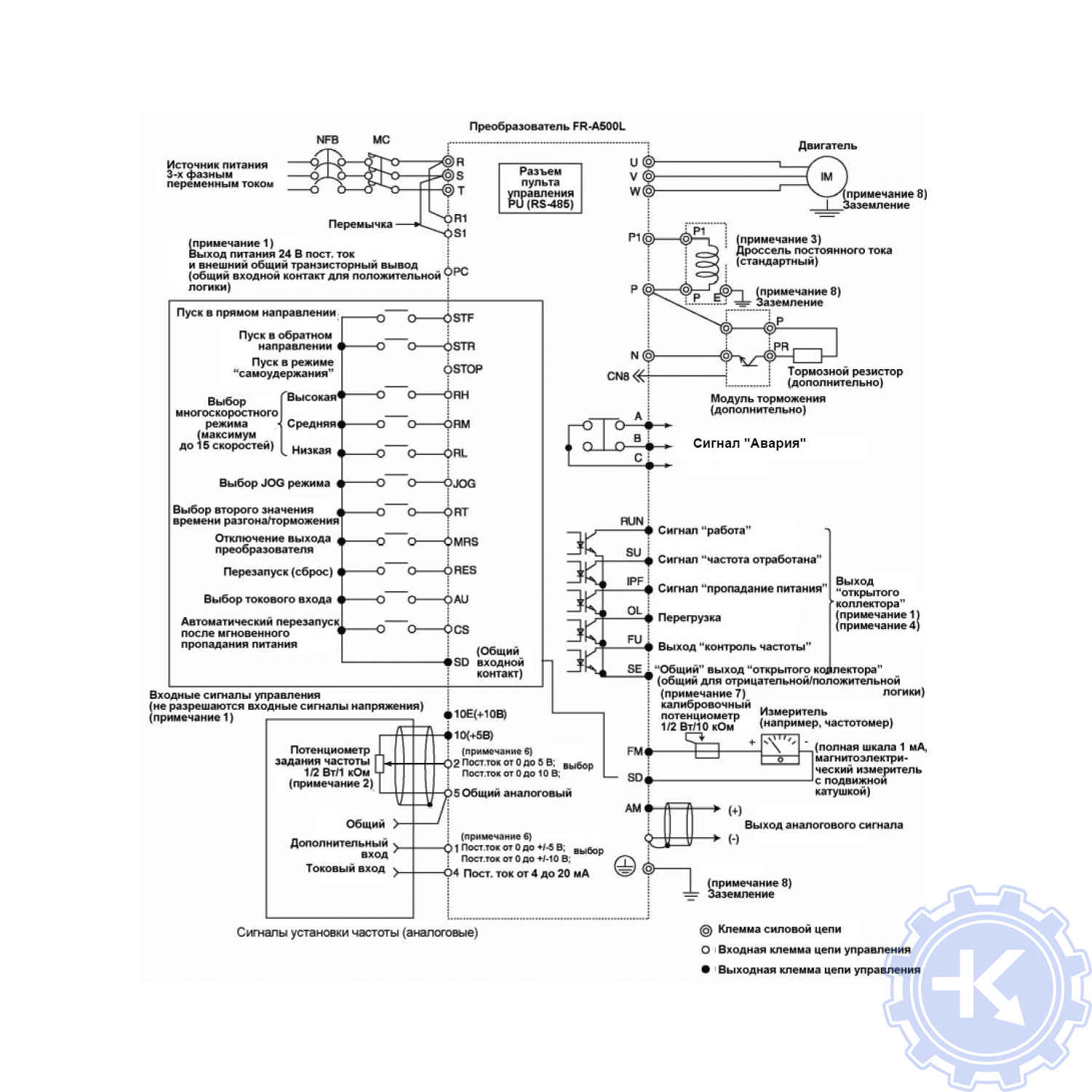

Схема подключения частотного преобразователя Mitsubishi FR-A800

Ремонт частотных преобразователей Mitsubishi в сервисном центре
Компания «Кернел» производит ремонт частотных преобразователей Mitsubishi с 2002 года. За время существования компании наши сотрудники накопили колоссальный опыт в ремонте преобразователей частоты такого известного производителя как Mitsubishi Electric. Ремонт подобного промышленного оборудования ответственное и сложное занятие, требующие максимальной отдачи, профессионализма и максимально полной материальной базе.
Специалисты нашего сервисного центра максимальное внимание уделяют качеству исполнения ремонта, программирования и настройке промышленных преобразователей частоты, не зависимо от производителя данного промышленного оборудования. Именно поэтому мы смело даем гарантию на все выполненные работы шесть месяцев.
Ремонт частотных преобразователей Mitsubishi производится исключительно с использованием оригинальных запасных частей, на компонентном уровне с применением высокотехнологичного оборудования, квалифицированным персоналом с инженерным образованием.
Мы ремонтируем все линейки частотных преобразователей, которые были выпучены за всю историю существования компании Mitsubishi Electric.
В случае выхода из строя преобразователя частоты на вашем производстве либо появились проблемы с приводом, которые вы не можете решить самостоятельно, мы всегда рады вам помочь. Специалисты нашего сервисного центра в минимальные сроки проведут глубокую диагностику с последующим ремонтом частотного преобразователя Mitsubishi. Оставьте заказ на ремонт промышленного оборудования используя форму на сайте, либо свяжетесь с нашими менеджерами, сделать это очень просто.
Как с нами связаться
У вас остались вопросы, связанные с ремонтом частотных преобразователей Mitsubishi? Задайте их нашим менеджерам. Связаться с ними можно несколькими способами:
- Заказав обратный звонок (кнопка в правом нижнем углу сайта)
- Посредством чата (кнопка расположена с левой стороны сайта)
- Позвонив по номеру телефона: +7(8482) 79-78-54; +7(917) 121-53-01
- Написав на электронную почту: 89171215301@mail.ru
Далеко не полный список производителей промышленной электроники и оборудования, ремонтируемой в нашей компании.
Источник
Преобразователь частоты митсубиси s500
Устройства предназначены для мощности до 3,7 кВт, напряжение сети питания: 1-фазная, либо 3-фазная сеть 220, 380 вольт, 50 герц.
Технические данные
- Интервал частоты выхода от 0,5 до 120 Гц.
- Пульт встроен.
- Функционирование по интерфейсу протокола RS
- 2 входа аналоговых: 0 — 20 мА, 0 — 10 В.
- Вольт – частотный режим.
- Автоматический перезапуск.
- 15 ступеней запрограммированных скоростей.
- Регулятор встроен.
- Токовая перегрузка 200%.
Сфера использования
- Агрегаты текстильного производства.
- Конвейерные линии.
- Дробильные установки.
- Ленты транспортеров.
- Мельничные комплексы.
- Станции насосов.
- Металлообрабатывающие станки.
- Системы вентиляции.
- Оборудование полиграфии.
- Деревообработка.
Компания Mitsubishi Electric произвела пополнение серии частотников компактными устройствами FR-S500. Эта фирма является лидером в выпуске частотных преобразователей. По ее продукции устанавливаются стандарты для различных производителей. Преобразователь S500 стал мощным прорывом в обновлении типов частотников. Габариты новых приборов значительно уменьшены. Последняя серия инверторов стала наиболее компактной по сравнению с аналогичными по характеристикам моделями.
Программное обеспечение выполнено по универсальному методу, поддерживается различными преобразователями. Пользователь, который ранее сталкивался с частотниками этой фирмы, легко сможет работать с приборами серии 500, сделать его настройку для запуска и эффективной работы.
Цифровой регулятор
При разработке конструкции частотника серии s500 руководствовались принципом быстроты настройки и простоты управления. Цифровой регулятор подобен джойстику мобильника или видеомагнитофона. Внедрение регулятора цифрового типа дало возможность замены обычных кнопок. Доступ к необходимым параметрам можно получить значительно проще. Такая возможность облегчает настройку частотника новыми операторами, исключает некорректность настройки.
Тот факт, что в преобразователе имеется порт интерфейса RS 485 для серии s500 дает возможность инверторам производить обмен данных с компьютером, применяя программное управление, и с ПЛК контроллером программируемого вида. Можно соединить до 32 частотных преобразователей. При необходимости есть возможность применить один из частотников серии s500 для наружного контроля. Например, это можно сделать для копирования значений свойств настройки при применении значительного количества оборудования, на серьезных промышленных объектах. А также на пульте диспетчера для удаленного доступа. Частотный преобразователь по-настоящему стал «глобальным игроком», есть в наличии сертификат ГОСТ. Он позволяет применять различную логику во время управления.
Фирма под названием Mitsubishi Electric создала для инверторов серии s500 инновационные элементы поддержания соответствующих стандартов повышенного качества. Транзисторный модуль обеспечен системой автоподдержания момента. Это векторный аналог, позволяющий достигать 150% от момента номинала при 6 герцах частоты. Частотники этой серии оснащены интегрированной системой контроля значения тока и ограничитель на электронных элементах возрастания тока для обеспечения защиты коммутирующих элементов.
Источник
Преобразователи частоты Mitsubishi FR-S 500 (S500 FR)
Каталог Mitsubishi
Широкий ассортимент современных приборов, которые представлены в виде частотных преобразователей Mitsubishi Electric, позволяет каждому клиенту подобрать необходимый тип оборудования, учитывая индивидуальные технические потребности. Модель частотного преобразователя Mitsubishi FR-S 500, которая является одной из наиболее востребованных на сегодняшний день, отличается высоким уровнем надежности и максимальной степенью дополнительной оснащенности. Оригинальный частотник Mitsubishi FR-S 500 рассчитан на подключение к однофазной и трехфазной сети с выходной мощностью от 0,2 до 1,5 кВт для однофазной сети и от 0,4 до 3,7 для трехфазного подключения.
Применение частотного преобразователя FR-S 500
Частотный преобразователь Mitsubishi FR-S 500, цена которого является наиболее низкой в нашей компании на сегодняшний день, широко используется в различных сферах жизнедеятельности современного человека. Их устанавливают на:
- специальное оборудование для обработки металлов и древесины;
- универсальное полиграфическое оборудование;
- станки текстильного производства;
- элементы управления сверлильными станками;
- разнообразное насосное оборудование;
- транспортеры, дробилки, мельницы, вентиляторы и прочее промышленное оборудование.
Оформление заказа
Для того чтобы частотный преобразователь Mitsubishi купить по наиболее выгодной цене необходимо обратиться к представителям нашей компании, которые всегда готовы предоставить максимально информативную консультацию в плане выбора и продажи оригинальной продукции.
Основные технические характеристики
Масса и габариты
Полный контроль одним нажатием: новый преобразователь частоты Mitsubishi Electric серии FR-S500
Поддержание концепции продукта
Mitsubishi Electric уже продемонстрировала преимущества концепции единообразия в таких сериях преобразователей частоты, как FR-E520, FR-E540, FR-A540, и их «большого брата» инвертора FR-A540L. И это начинание было продолжено во всей серии преобразователей частоты FR-S520 иFR-S540. Стандартизированные операции по настройке, также являются ключевым элементом для всей 500-й серии, то есть человек который сталкивался хотя бы с одним из преобразователей частоты Mitsubishi Electric 500-й серии, будет способен работать с любым из преобразователей частоты серии 500. Специально разработанное программное обеспечение поддерживается исключительно всеми преобразователями частоты всех серий. С помощью данного программного обеспечения даже неопытный пользователь сможет настроить преобразователь частоты для его нужд и запустить его в работу быстро и эффективно.
Настройка с помощью встроенного цифрового поворотного регулятора
Простота, быстрота настройки были приоритетными направлениями при разработке преобразователя частоты серии FR-S520 и FR-S540. Впечатляющим результатом данных усилий явился «Digital Dial» (цифровой регулятор), который напоминает джойстики для управления современными видеомагнитофонами и мобильными телефонами. Введение цифрового поворотного регулятора позволило заменить стандартные кнопки и теперь намного проще получить доступ к 12 наиболее важным параметрам настройки преобразователя частоты. Это нововведение весьма облегчило настройку преобразователя частоты новыми пользователями и практически исключает некорректную настройку преобразователя частоты — это абсолютно новое разработка.
Глобальный игрок
Наличие порта RS-485 (для преобразователя частоты серии FR-S500…ECR) позволяет инверторам FR-S500 обмениваться данными как с компьютером (используя программное обеспечение VFD-Setup), так и с программируемым логическим контроллером (ПЛК), соединяя в сеть до 32 преобразователей частоты. Если необходимо, то возможно использовать один из преобразователей частоты 500-й серии для внешнего контроля, например для копирования параметров настройки при использовании большого количества станков и на больших предприятиях, или для удаленного контроля на диспетчерском пульте. Преобразователь частоты действительно является «глобальным игроком», имея сертификат ГОСТ, CE, UL и cUL, а также позволяющий использовать как положительную, так и отрицательную логику при управлении.
И снова Mitsubishi Electric разработала для преобразователей частоты серии FR-S520 и FR-S540 новые элементы hardware для поддержания необходимых стандартов высокого качества и функциональности. Новый силовой транзисторный модуль снабжен системой автоматического поддержания момента, что является в некотором роде аналогом векторного управления — это позволяет развивать 150% номинального момента уже при 6 Гц. Преобразователи частоты FR-S520 и FR-S540 также имеют интегрированную систему мониторинга величины тока и электронный ограничитель нарастания тока для защиты выключателей и контакторов.
Дополнительная информация, консультации, цены
Мы предложим эффективное и экономичное решение. Воспользуйтесь опытом наших технических специалистов — заполните форму справа, или позвоните.
Частотно-регулируемые привода, устройства плавного пуска Mitsubishi Electric, Control Techniques.
Источник
-
Mitsubishi FR — S500 — page 1
FR — S 500 T RANS I S T O RI Z E D I NV E RT E R IN S T R U C T IO N M A N U A L (D e ta i l e d ) Ch a p t e r 3 Ch a p t e r 2 Ch a p t e r 4 F UNCT I O NS Ch a p t e r 1 W I RI NG F UNCT I O NS SPEC I F I C AT I O N S PR O T EC TI VE HE A D O F F I CE: M I T SUB I S HI D ENK I B L DG M A RUNO UCHI T O K Y O 1 0 0 — 8 3 1 0 P r i nt ed i n J apan …
-
Mitsubishi FR — S500 — page 2
A-1 Thank you for choosing this Mitsubishi Transistorized inverter. This instruction manual (detailed) provides instructions for advanced use of the FR-S500 series inverters. Incorrect handling might cause an unexpected fault. Before using the inverter, always read this instruction manual and the instruction manual (basic) [IB-0600026] packed with …
-
Mitsubishi FR — S500 — page 3
A-2 2. Fire Prevention CA UTION Mount the inverter to incombustible material. M ounting it to or near co mbustible material can cause a fire. If the inverter has become faulty, switch off the inverter power. A continuous flow of large current could cause a fire. Do not connect a resis tor directly to the DC terminals P( + ), N( − ). This could ca …
-
Mitsubishi FR — S500 — page 4
A-3 (2) W iring CA UTION Do not fit capacitive equipment such as power factor correction capacitor, radio noise filter or surge suppressor to the output of the inverter. The connection orientation of the output cable s U, V, W to the m otor will affect the direction of rotation of the motor. (3) Trial run CA UTION Check all parameters, and ensur e …
-
Mitsubishi FR — S500 — page 5
A-4 (6) Maintenance, inspection and parts replacement CA UTION Do not carry out a megger (insulation resist ance) test on the c ontrol circuit of the inverter. (7) Disposing of the inverter CA UTION Treat as industrial waste. (8) General i nstructions Many of the diagrams and drawings in this instruction manual show the inverter without a cover, or …
-
Mitsubishi FR — S500 — page 6
I CONTENTS 1. WIRING 1 1.1 Japanese Version …………………………………………………………………………. 2 1.1.1 Term inal c onn ection diagram ………………………………………………………….. 2 1.1.2 Layou t and wir ing of m ain circu it term inals ……………………………………….. 3 1.2 N …
-
Mitsubishi FR — S500 — page 7
II 1.8.3 Curr ent i nput s elec tion «AU si gnal «: Set ting «4» ……………………………….. 38 1.8.4 Start self -hol ding s electi on (ST OP s ignal) : S etting «5»……………………… 38 1.8.5 Out put sh ut-of f (MR S signa l): Sett ing «6» ………………………………………… …
-
Mitsubishi FR — S500 — page 8
III 2.6.2 Set ting dial function selectio n ………………………………………………… 83 2.6. 3 Mo nitor ing r efere nce …………………………………………………….. 84 2.7 Restart Opera tion Param eters ……………………………………………………… 84 2.7. 1 Res tart s etti ng ………………. …
-
Mitsubishi FR — S500 — page 9
IV 3. PROTECTIVE FUNCTIONS 136 3.1 Errors (Alarms) ………………………………………………………………………….137 3.1.1 Error ( alarm ) defi nitio ns ……………………………………………………………….. 13 7 3.1.2 To know the ope rating st atu s at the oc curren ce of alarm (Onl y when FR-P U04 is use …
-
Mitsubishi FR — S500 — page 10
1 1 This chap ter explains th e basic «w iring» for use o f this product. Al ways read the instructions be f ore use . For description of «installation», refer to the instruction manual (basic ). 1.1 Japanese Ve rsion ………………………………………………2 1.2 No rth A merica V ersion ……………………… …
-
Mitsubishi FR — S500 — page 11
2 1 .1 Japanese Ver sion 1 .1.1 Ter minal connection diagram FR-S520-0.1K to 3.7K (-R) (-C) FR-S540-0.4K to 3.7K (-R) Power f actor impr oving DC reactor (FR- BEL: Opt ion) PC Extern al transistor comm on 24VDC pow er supply Contac t input c ommon ( source) STF STR RH RM RL SD Forward rotation s ta rt Reverse rotation sta rt Middle High Low Frequen …
-
Mitsubishi FR — S500 — page 12
3 1 CAU TION To prevent a malfunct ion due t o noise, k eep the si gnal cables more than 10c m (3.94inc hes) away from t he po wer cabl es. FR-S520S-0.1K to 1.5K (-R) (-C) FR-S510W -0.1K to 0.75K (-R) Powe r su pply NFB R S Motor IM Earth ( Ground ) U V W MC REMARKS • To ensure safety, connect the po wer input to the inverter v ia a ma gnetic con …
-
Mitsubishi FR — S500 — page 13
4 1 .2 North America Ver sion 1 .2.1 Ter minal connection diagram FR-S520-0.1K to 3.7K-NA FR-S540-0.4K to 3.7K-NA (R) Powe r factor im proving DC reactor (FR-BEL: Optio n) 3- ph ase AC power sup ply NFB R S T PC External transistor common 24VDC p ower su pply Conta ct inpu t comm on (source ) STF SD Forward rota tion start Reverse rotati on start M …
-
Mitsubishi FR — S500 — page 14
5 1 NOTE To prevent a malfunction due to noise, keep the signal cables more than 10cm (3.94inches) away from the power cables. FR-S510W -0.1K to 0.75K-NA Power supp l y NFB R S Motor IM Earth ( Ground ) U V W MC REMARKS • To ensure safety, connect the power input to the inverter via a magnetic contactor and earth leakage circuit break er or no-fu …
-
Mitsubishi FR — S500 — page 15
6 <When single-p hase power input is pro vided for three-phase p ower input inverter (NA version o nly)> Reduce the output current. FR-S520- K-NA inverter 0.1 0.2 0 .4 0.75 1.5 2.2 3 .7 Rated output current (A) 0.4 0.8 1. 5 2.5 4.0 5.0 7. 0 Power supply capacit y (kVA) 0.4 0.8 1. 5 2.5 4.5 5.5 9. 0 AC input current (A ) 1.1 2.4 4. 5 6.4 11.2 …
-
Mitsubishi FR — S500 — page 16
7 1 1 .3 European Version 1 .3.1 Ter minal connection diagram FR-S540-0.4K to 3.7K-EC(R) Power factor improving DC reactor (FR-BEL: Option) Frequency setting signals (Analog) 10 ( +5V ) 2 2 3 1 4 to 20mADC (+) 4 (4 to 20 m A DC ) Frequency setting pote nti omet er 1/2W 1k (*3) SE Runn ing Jum per : R emove this jumper when FR-BEL is connected. Moto …
-
Mitsubishi FR — S500 — page 17
8 FR-S520S-0.2K to 1.5K-EC (R) Power supply NFB L 1 N Motor IM Eart h (Ground) U V W MC REMARKS • To ensure safety, connect the power input to the inverter via a magnetic contactor and earth leakage ci rcuit breaker or no-fuse break er, and use the magnetic contactor to switch power on-off . • The output is three-phase 200V. NOTE • To prevent …
-
Mitsubishi FR — S500 — page 18
9 1 1 .4 De scr i pti o n of I/ O T e r min a l Spec ifi c ati ons 1 .4.1 Main circuit Symbol Termi nal Name Descript i on R, S, T * <L 1 , L 2 , L 3 > AC power input Connect t o the commer ci al power s uppl y. U, V, W Invert er output Connect a three- phas e squir rel-c age motor. N<-> DC voltage common DC volta g e common t erminal. …
-
Mitsubishi FR — S500 — page 19
10 Symbol Terminal Name Descript i on Input si gnal s 5 Frequenc y setti ng i nput common Common termi nal for t he frequenc y settin g si g nals (ter mi nals 2, 4) and i ndicat or connect ion (ter minal AM). Isol at ed from t er minals SD and SE. Do not earth. A B C Alarm output Change-o ver cont act out put indic at ing that t he out put has be e …
-
Mitsubishi FR — S500 — page 20
11 1 1 .5 How to Use the Main Circuit Te rminals 1 .5.1 Cabl es, wiring lengths, crimping ter minals, etc. The following selection example assumes the wiring length of 20m (65.62feet). 1) FR-S520-0.1K to 3.7K (-R) (-C) FR-S520-0.1K to 3.7K-NA Cables PVC Insu lated Cables Crimpi ng Termin als mm 2 AWG mm 2 Applic able Invert er Model Termin al Screw …
-
Mitsubishi FR — S500 — page 21
12 W ir ing length 100m (328.08feet) maximum. (50m (164.04f eet) maximum for the FR-S540-0.4K.) CAU TION • W hen the wiring length of the 0.1K or 0.2K is 30m (98.43feet) or more, use the carrier frequency to 1kHz. • Use the carrier frequency of 1kHz when the wiring length of the FR-S540-0.4K, 0.75K is 30m (98.43feet) or more. • The wiring len …
-
Mitsubishi FR — S500 — page 22
13 1 1 .5.3 P eripheral dev ices (1) Selection of peripheral devices Check the capacity of the motor applicable to the inverter you purchased. Appropriate peripheral devices must be selected according to the capacity. Refer to the following list and prepare appropriate peripheral devices: 1) FR-S520-0.1K to 3.7K (-R) (-C) FR-S520-0.1K to 3.7K-NA Ca …
-
Mitsubishi FR — S500 — page 23
14 3) FR-S520S-0.1K to 1.5K (-R) FR-S520S-0.2K to 1.5K-EC (R) Cables (mm 2 ) (*2) Motor Output (kW (HP)) Invert er Model Rated curr ent of Circuit Breaker (Refer to page 15) (*1) Magnetic Contactor (MC) (Refer to page 17) Power Factor Improvi ng AC Reactor (Refer to page 18) (*3) Power Factor Improvi ng DC Reactor (Refer to page 18) (*3) R, S <L …
-
Mitsubishi FR — S500 — page 24
15 1 1 .5.4 Leakag e cur rent and i nstal lati on of eart h leakag e ci r cui t br eaker Due to static capacitances existing in the inverter I/O wiring and motor, leakage currents fl ow through them. Since their values depend on the static capacitances, carrier frequency, etc., take the following counter measures. (1) To-ground leakage currents Lea …
-
Mitsubishi FR — S500 — page 25
16 (3) Selecting the rated sensitivity current f or the earth leakage circuit breaker W hen u sing the earth leak age circuit breaker with the inverter circuit, select its rated sensitivity current as follows, independently of the PWM carrier frequency: Progressive Super Series (Type SP, CF, SF, CP) Rated sensitivity current: I ∆ n ≥ 10 × (lg1 …
-
Mitsubishi FR — S500 — page 26
17 1 1 .5.5 Pow er-off and magn etic contactor (M C) CAU TION Do not use the inverter power supply side magnetic contactor to s tart or stop the inverter. As shown on the right, always use the start signal (ON or OFF ac ross terminals STF or STR-SD) to make a start or stop. (Refer to page 28) Powe r supply NFB F OFF ON MC MC RA R<L 1 > S< …
-
Mitsubishi FR — S500 — page 27
18 1. 5.6 Regardi ng the i nstall ati on of the power factor impr ov i ng reactor W hen the inverter is installed near a large-capac ity power transformer (500kVA or more at the wiring length of 10m (32.81feet) or less ) or the power capacitor is to be switched, an excessive peak cur rent will flow in the power supply input cir c uit, damaging the …
-
Mitsubishi FR — S500 — page 28
19 1 Noise reduction examples Inverter FR- BIF Sens or Use 4-c ore cabl e for m oto r power cable and use one cable as e art h cable. Power supply for sensor Use twisted pair shielded cable. Inverter powe r su ppl y Control powe r su ppl y Do not earth shield but connect it to signal common cable. Sepa rat e in v ert e r an d po we r line more than …
-
Mitsubishi FR — S500 — page 29
20 1 .5.9 Reg ardi ng pow er har moni cs The inverter may generate power har monics from its converter circuit to affect the power generator, power capacitor etc. Power har monics are different from noise and leakage currents in sourc e, frequency band and transmission path. Take the following counter measure suppression tec hniques. The following …
-
Mitsubishi FR — S500 — page 30
21 1 2) «Harmonic suppression guideline for specific consumers» This guideline sets forth the maximum values of harmonic currents outgoing from a high-voltage or specially high-voltage consumer who will insta ll, add or renew harmonic generating equipment. If any of the maximum values is exceeded, this guideline requires that consumer to …
-
Mitsubishi FR — S500 — page 31
22 Table 2 Conversion Factors for FR-S500 Series Class Circuit Type Conversio n Factor (K i ) W ithout reac tor K31 = 3. 4 W ith reactor (AC si de) K32 = 1.8 W ith reactor (DC si de) K33 = 1.8 3 3-phase br idge (Capaci tor- smoot hed) Wit h reac tors ( A C, DC si des) K34 = 1.4 Table 3 Equivalent Ca pacity Limits Received Pow er Volt age Referenc e …
-
Mitsubishi FR — S500 — page 32
23 1 Table 5 Rated Capacities an d Outgoing Harmoni c Currents for In ver ter Drive Rated Curre nt [A ] Fundamen tal Wave Cu rrent Con verted from 6 .6kV (No react or, 100 % oper at ion rati o) Applied Motor (kW) 4 00V 6.6kV Equi vale nt of Fundam ent al Wave Cur rent (mA) Rated Capac ity (kVA) 5 th 7th 11th 13th 17th 19th 23rd 25th 0.4 0 . 81 49 0 …
-
Mitsubishi FR — S500 — page 33
24 1 .6 How to U se the Control Cir cuit Terminals 1 .6.1 Ter minal block lay out In the control circuit of the inverter, the terminals are arranged as shown below: Terminal screw size : M2 10 2 5 4 RL RM RH FM Terminal ar r angeme nt of control circuit <AM> Japanese version NA, EC v ersion Terminal sc rew size : M3 A RUN STR PC SE SD SD STF …
-
Mitsubishi FR — S500 — page 34
25 1 1 .6.3 Cha nging the c ontrol logic The input signals are set to sink logic for the Japanese and NA version, and to source logic for the EC version. To change the control logic, the connector under the setting dial must be moved to the other position. Change the connector position using tweezers, a pair of long- nose pliers etc. Change the con …
-
Mitsubishi FR — S500 — page 35
26 1) Sink logic type In this logic, a signal switches on when a current flows out of the corresponding signal input terminal. Terminal SD is common to the contact input signals. Terminal SE is com mon to the open collector output signals. AX40 SE RUN 24VDC STR STF SD R 1 9 R R R A curren t flows out of the corres pondi ng signal RUN Inverter Curre …
-
Mitsubishi FR — S500 — page 36
27 1 2) Source logic type In this logic, a signal switches on when a current flows into the corresponding signal input terminal. Terminal PC is common to the contact input signals. For the open collector output signals, terminal SE is a positive external power supply terminal. STF STR PC AX80 24VDC RUN SE 1 9 R R R R A current flo ws out of the cor …
-
Mitsubishi FR — S500 — page 37
28 1 .7 Input Terminals 1 .7.1 Run (sta rt ) and sto p (STF , ST R, ST OP) To start and stop the motor, f irst switch on the input power supply of the inverter (switch on the magnetic contactor, if any, in the input circuit during preparation for operation), then start the motor with the forward or reverse rotation start s i gnal. (1) Two-wire type …
-
Mitsubishi FR — S500 — page 38
29 1 (2) Three-wire ty pe connect i on (STF, STR, STOP) A three-wire type connection is shown on the right. Assign the start self-holding signal (STOP) to any of the input terminals. To make a reverse rotation start, set Pr. 63 to «- — -» ( fact or y settin g) . 1) Short the signal S TOP-SD to enable the start self-holding f unction. In t …
-
Mitsubishi FR — S500 — page 39
30 DC inje c tio n brake operation tim e P r. 11 Output f requency Start ing freq uency Pr.13 (*1) 0.5Hz ON DC injection brake operat ion freq uency Pr. 10 3Hz 0.5s DC injecti on brake o perati on time P r. 11 0.5Hz 0.5 s ON 0.5Hz ON 3Hz Coasted to a stop Tim e DC injection brake not o perated DC injectio n brake disabled DC injectio n b r ake enab …
-
Mitsubishi FR — S500 — page 40
31 1 1 .7.2 Con nection of freq uency setting potentiometer and output frequency meter (10, 2, 5, 4, AU) The analog frequency setting input signals that may be entered are voltage and current signals. For the relationships between the frequency setting input voltages (currents) and output frequencies, refer to the following diagram. The frequency s …
-
Mitsubishi FR — S500 — page 41
32 (2) Cu rrent inpu t (4, 5 , A U) To automatically perform operation under constant press ure or temperature control using a fan, pump etc., enter the controller output signal of 4 to 20mADC across terminals 4-5. Terminals AU-SD must be shorted to use the 4 to 20mADC signal for operation. (Assign the signal AU using any of Pr. 60 to Pr. 63.) W he …
-
Mitsubishi FR — S500 — page 42
33 1 Multi-Speed Setti ng Termina l Input Speed RE X- SD* RH- SD RM- SD RL- SD Param eter Set Freq uenc y Range Re mark s Speed 1 (high speed) OF F ON OFF OFF Pr. 4 0 to 120Hz ——————— Speed 2 (middl e speed) OF F OFF ON OFF Pr. 5 0 to 120Hz ——————— Speed 3 (low speed) OF F OFF OFF ON Pr. 6 0 to 120Hz ——————? …
-
Mitsubishi FR — S500 — page 43
34 1 .7.4 Indi cator connectio n and adjustm ent (1) Japanese version (FM) The output frequency, etc. of the inverter can be indicated by a DC a mmeter of 1mA full-scale deflection and maximum 300 Ω internal resistance or a commercially available digital indi c ator which is connected across terminals FM-SD. The indicator can be calibrated f rom …
-
Mitsubishi FR — S500 — page 44
35 1 Outpu t wave form of te rminal F M The output signal of terminal FM has a pulse waveform as shown in the table below and the number of its pulses is proportional to the inverter output frequency. The output voltage (average voltage) is also proportional to the output f requency. Terminal FM Output Voltage Specifications Output wav ef or m Cali …
-
Mitsubishi FR — S500 — page 45
36 Digital indicator Since the digital indicator counts and displays the num ber of pulses, adjust it from the operation panel or parameter unit. The inverter output, at which the referenc e pulses of 1440 pulse s /s are output, can be set in Pr. 55 when frequency monitoring is used as reference, or in Pr. 56 when current monitoring is used as refe …
-
Mitsubishi FR — S500 — page 46
37 1 1 .7.5 Co ntrol circuit common te rminals (SD, 5, SE) Terminals SD, 5, and SE are all comm on te rminals (0V) for I/O signals and are isolated from each other. Terminal SD is a common terminal for the contact input terminals (STF, STR, RH, RM, RL) and frequency output signal (FM). Terminal 5 is a common terminal for the frequency setting analo …
-
Mitsubishi FR — S500 — page 47
38 1 .8 How to U se the Input Signa ls (Assigned Terminals RL, RM, RH, STR) Pr. 60 «RL terminal functi on selection» Pr. 61 «RM terminal function selection» Pr. 62 «RH terminal function selecti on» These terminals can be changed in function by setting Pr. 60 to Pr. 63. Pr. 63 «STR terminal functio n selection» …
-
Mitsubishi FR — S500 — page 48
39 1 1 .8.5 Outpu t shut-off (MR S signal): Setting «6» Short the output stop terminal MRS-SD during inverter output to cause the inverter to immediately stop the output. Open terminals M RS-SD to resume operation in about 10ms. Terminal MRS may be used as described below: (1) To stop the mot or by mechanical brake (e.g. electromagnet ic …
-
Mitsubishi FR — S500 — page 49
40 1 .8.7 Jog o peration (JOG si gnal): Setting «9» (1) Jog operation using ex t ernal si gnals Jog operation can be started/stopped by shorting the jog mode select ter minal JOG- SD and shorting/opening the start signal te rminal STF or STR-SD. The jog frequenc y and jog acceleration/decelera tion time are set in Pr . 15 (factor y settin …
-
Mitsubishi FR — S500 — page 50
41 1 1 .8.9 PID c ontrol vali d terminal: Se tting «14» To exercise PID c ontrol, turn on the X14 signal. W hen this signal is off, ordinary inverter operation is performed. For more information, refer to page 101. ♦ ♦ ♦ ♦ Related parameters ♦ ♦ ♦ ♦ Pr. 88 «PI D ac tion s election», Pr . 89 «PID pr opor tion …
-
Mitsubishi FR — S500 — page 51
42 (2) RS-485 communication Use the RS-485 connector to perf orm communication operation f rom a personal computer etc. By connecting the RS-485 connector to a computer such as a personal c omputer, Factory Automation unit (HMI etc.) or other co mputer, by the communication cable, you can operate/monitor the inverter and read/write the parameter va …
-
Mitsubishi FR — S500 — page 52
43 1 Use the connectors, c ables and converter which are available on the market. Introduced products (as of June, 2000) *1. Connector: RJ45 connector Example: 5-554720-3, Tyco Electronics Corporation *2. Cable : Cable conforming to EIA568 (such as 10BASE-T cable) Example: SGLPEV 0.5mm × 4P (Twisted pair c able, 4 pairs), Mitsubishi Cable Industri …
-
Mitsubishi FR — S500 — page 53
44 1 .10 Design In formation 1) Provide electrical and mechanical interlocks for MC1 and MC2 which are used for commercial power supply-inverter switch-over. W hen there is a comm ercial power s upply-inverter switch-over circuit as shown below, the inverter will be dam aged by leakage current from the power supply due to arcs generated at the time …
-
Mitsubishi FR — S500 — page 54
45 2 Chapt er 1 Chapt er 2 Chapt er 3 Chapt er 4 This chapter explains the «functions» for use of this product. For simple variable-speed operation of the inverter, the factory settings of the parameters may be used as they are. Set the neces sary parameters to meet the load and operational specifications. Refer to the instruction manual …
-
Mitsubishi FR — S500 — page 55
46 2 .1 Function (Pa rameter) List Param eter I ndic a- tion Name Setti ng Range Minim um Setti ng Incr eme nts Fact ory Setti ng <EC version> Refer To: Cus- tomer Setti ng 0 Torque boos t 0 t o 15% 0.1% 6%/5%/ 4% (Note 1) 58 1 Maximum frequ ency 0 to 120H z 0.1Hz 60Hz <50Hz> 59 2 Minimum fr equency 0 to 120Hz 0. 1Hz 0Hz 59 3 Base fr eq …
-
Mitsubishi FR — S500 — page 56
47 2 Func — tion Pa- rame- ter Indi ca- tion Name Setting Ra nge Mini mum Setti ng Incr eme nts Fact or y Setti n g <EC versi on> Refer To: Cus- tomer Setti n g 15 Jog freq uency 0 to 120 Hz 0 .1Hz 5Hz 67 16 Jog accele ration/ decel erat io n time 0 to 999s 0.1s 0.5 s 67 17 RUN ke y rotation direc ti on selection 0: For war d rot ati on, 1: R …
-
Mitsubishi FR — S500 — page 57
48 Func — tion Pa- rame- ter Indi ca- tion Name Setting Ra nge Mini mum Setti ng Incr eme nts Fact ory Setti ng <EC versi on> Refer To: Cus- tomer Setti ng 29 Accelera ti on/ decel erat io n patt ern 0: Linear a cceleration/ decel erat io n, 1: S-patter n acceler ation/ decel eratio n A , 2: S-patter n acceler ation/ decel eratio n B 10 7 1 3 …
-
Mitsubishi FR — S500 — page 58
49 2 Func — tion Pa- rame- ter Indi ca- tion Name Setting Ra nge Mini mum Setti ng Incr eme nts Fact or y Setti n g <EC versi on> Refer To: Cus- tomer Setti n g 48 Outp ut cur rent detec ti on le vel 0 to 200% 1% 150% 80 49 Outp ut cur rent detec ti on sign al del ay time 0 to 10 s 0.1s 0s 80 50 Zero c urr ent detec ti on le vel 0 to 200% 1% …
-
Mitsubishi FR — S500 — page 59
50 Func — tion Pa- rame- ter Indi ca- tion Name Setting Ra nge Mini mum Setti ng Incr eme nts Fact ory Setti ng Ref er To: Cus- tomer Setti ng 60 RL ter min al funct io n selection 10 8 8 61 RM ter minal funct io n selection 11 8 8 62 RH ter minal funct io n selection 12 8 8 63 STR ter mi nal funct io n selection 0: RL, 1: RM, 2: RH, 3: RT, 4: AU, …
-
Mitsubishi FR — S500 — page 60
51 2 Func — tion Pa- rame- ter Indi ca- tion Name Setting Ra nge Mini mum Setti ng Incr eme nts Fact or y Setti n g Refer To: Cus- tomer Setti n g 74 Input filter time const ant 0: 2-s te p movi ng aver age pr ocess ing 1 to 8: Exp onenti al av erag e valu e of 2n at t he setting o f n 11 9 4 75 * Reset selection/PU stop selection 0: Res et n orm a …
-
Mitsubishi FR — S500 — page 61
52 Func — tion Pa- rame- ter Indi ca- tion Name Setting Ra nge Mini mum Setti ng Incr eme nts Fact ory Setti ng Ref er To: Cus- tomer Setti ng 84 * Multi-speed setting (speed 12) 0 to 120Hz , — — — 0.1Hz — — — 61 85 * Multi-speed setting (speed 13) 0 to 120Hz , — — — 0.1Hz — — — 61 86 * Multi-speed setting (speed 14) 0 to 120Hz , — — — 0.1Hz — — — …
-
Mitsubishi FR — S500 — page 62
53 2 Func — tion Cali bra- tion param e- ters Indi ca- tion Name Setting Range Minim um Setti ng Incr e- ments Fact ory Settin g Refer To: Cus- tomer Settin g <Japa- nese> 900 FM t ermi nal calibration C1 <NA, EC> 901 AM t ermina l calibration 111 C2 (9 02) Frequency setting volt age bi as frequency 0 to 60H z 0.1H …
-
Mitsubishi FR — S500 — page 63
54 Func — tion Com- muni- cati on Param e- ter Indi ca- tion Name Setting Range Minim um Setti ng Incr e- ments Fact ory Setting <NA, E C version> Refer To: Cus- tomer Setting n5 (3 35) Numb er of commun ication retries 0 to 10, — — — 1 1 118 n6 (3 36) Comm unic ati on check time interval 0 to 999s, — — — 0.1 s 0s <- — — > 118 n7 (3 37) …
-
Mitsubishi FR — S500 — page 64
55 2 Func — tion Com- muni- cati on Param e- ter Indi ca- tion Name Setting Range Minim um Setti ng Incr e- ments Fact ory Setting Refer To: Cus- tomer Setting n16 (992) * PU ma in display screen dat a selectio n 0: Selec table between output frequenc y and output curr ent 100: (during stop): Set frequency, output current (during operation): Out pu …
-
Mitsubishi FR — S500 — page 65
56 2 .2 List o f Parameters Classified by Purpose o f Use Set the parameters according to the operating conditions. The following list indicates purpose of use and corresponding parameters. Para meter Num bers Purpose of Us e Parameter number s which must be s et Use of exte nded func t ion paramet ers Pr. 30 Operati on mo de selec t ion Pr. 53 , P …
-
Mitsubishi FR — S500 — page 66
57 2 Para meter Num bers Purpose of Us e Parameter number s which must be s et Frequenc y meter c al ibrati on Pr . 54, Pr . 55, Pr. 56, Calibrat ion paramet er C1 Displ ay of monitor on c ontrol panel or parameter uni t (FR- PU04) Pr. 52, Communic ation paramet er n16 Related to monitor ing Displ ay of speed, et c Pr. 37, Pr. 52 Functi on write pr …
-
Mitsubishi FR — S500 — page 67
58 2 .3 Explanation of Functions (Parameter s) 2 .3.1 T orq ue boos t Increase this value for use when the inverter-to-motor distance is long or motor torque is insufficient in the low speed range (stall prevention is activated). Motor torque in the low-frequency range can be adjusted to the load to increase the starting motor torque. Pr. 0 Pr. 46 …
-
Mitsubishi FR — S500 — page 68
59 2 2 .3.2 Max imum and minim um freq uency You can clamp the upper and lower limits of the output frequency. Outpu t f requency (Hz) Pr.1 Pr.2 Set frequen cy 5,10 V (20mA) 0 (4mA) Parameter Name Factor y Setting <EC version > Setting Range 1 Ma ximum f requenc y 60Hz <50Hz> 0 to 120H z 2 Mini mum frequenc y 0Hz 0 to 120Hz <Setting& …
-
Mitsubishi FR — S500 — page 69
60 Param eter Na me Fa ctor y Setting <EC version> Setti ng Range Re mark s 3 Base fr equency 60Hz <50Hz> 0 to 120H z 19 Base fr equency voltage — — — <888> 0 to 500V, 888, — — -*1 888: 95% of p ower suppl y volt age* 2 — — — : Same as power supply voltage* 3 Setting i s enabled wh en Pr. 30 = «1». 47 Second V/F ( …
-
Mitsubishi FR — S500 — page 70
61 2 2 .3.4 Mul ti -spe ed operation to to Used to switch between the predetermined running speeds. Any speed can be selected by merely switching on/off the corresponding contact signals (RH, RM, RL, REX signals ). By using these functions with Pr. 1 «maximum frequency» and Pr. 2 «minimum frequency», up to 17 speeds can be s et. …
-
Mitsubishi FR — S500 — page 71
62 CAU TION 1. The mult i -speed s ettings overri de the main speeds (acr oss ter minals 2- 5, 4-5, set t ing dial) . W hen the multi-s peed s etti ngs and setti ng di al are us ed i n the combi ned o perati on mo de (Pr. 79=3), the mul ti-s peed s etti ngs have pr ecedenc e. 2. The mult i -speeds can als o be s et in the PU or ext ernal op eration …
-
Mitsubishi FR — S500 — page 72
63 2 <Setting> Use Pr. 7 and Pr. 44 to set the acceleration time required to reach the frequency set in Pr. 20 from 0Hz. Use Pr. 8 and Pr. 45 to set the deceleration time required to reach 0Hz from the frequency set in Pr. 20. Pr. 44 and Pr. 45 are valid when the RT signal is on. (*) Set «- — -» in P r. 45 to mak e the d ecelera tio …
-
Mitsubishi FR — S500 — page 73
64 2 .3.6 Elec tronic overcur rent protec tion Set the current of the electronic overcurrent protec tion to protect the motor from overheat. This feature provides the optimum protective characteristics, including reduced motor cooling capability , at low speed. Parameter Name Factory Setting Sett ing Range 9 Elec tronic thermal O/ L r elay R at ed …
-
Mitsubishi FR — S500 — page 74
65 2 Param eter Na me Fa ctor y Setting S etting Range Re mark s 10 DC inject i on brake operati on f requenc y 3Hz 0 to 120Hz 11 DC inject i on brake operati on t ime 0.5s 0 to 10s 12 DC injecti on brake vol t age 6% 0 to 15% Setti ng i s enabled wh en Pr. 30 = «1». (W hen Pr . 11 is set to «0s» or Pr . 12 is set t o «0%&q …
-
Mitsubishi FR — S500 — page 75
66 2 .3.9 Load pattern sel ection You can select the optimum output characteristic (V/F characterist ic) f or the application and load characteristics. Forward rotatio n Reverse rotatio n For co nstant-tor que loads (e.g. conveyor , cart) 100% Output voltage Base fr equency Outpu t frequenc y (Hz) Pr.14= 0 For varia ble-torque loads (Fan, pump ) 10 …
-
Mitsubishi FR — S500 — page 76
67 2 2 .3.10 J og frequency To perform jog operation in the external operation mode, choose the jog operation function in input terminal function selection, turn on the jog signal, and use the start signal (STF, STR) to make a start or stop. For the type having the RS-485 communication function, you can choose the jog operation mode from the parame …
-
Mitsubishi FR — S500 — page 77
68 2 .3.12 Stall preventi on function and c urrent limi t function You can make settings to disable stall prevention caused by overcurrent and to disable the fast-response current limit (which limits the current to prevent the inverter from resulting in an overcurrent trip if an ex c essive current occurs due to sudden load variation or ON-OFF, etc …
-
Mitsubishi FR — S500 — page 78
69 2 CAU TION • * W hen «Operation not c ontinued for OL signal output» is s elected, the «OL T» alarm code (stopped b y stall prevention) is dis played and operation s topped. (Alarm stop display » «) • If the load is heavy, the lift is predetermined, or the acceleration/deceleration time is short, the stall preve …
-
Mitsubishi FR — S500 — page 79
70 120Hz Pr.22 Pr.28 Pr.23 Stall prevention operation level (%) Outpu t frequency (Hz ) Reduction ratio compensation factor (%) =»- — -» Pr.23 When Setting exa m ple (Pr.22=150%, Pr.23=100% , Pr. 28=60Hz) 150 90 75 0 60 80100120 112.5 Stall p revention operatio n level (%) Output frequency (Hz ) <Setting> Generally, set 150% (factor …
-
Mitsubishi FR — S500 — page 80
71 2 2 .3.14 Acceleration/decel er ation pattern Set the acceleration/deceleration pattern. Output frequenc y (Hz) fb Time [S-shape d acceler ati on/ decel er ati on A ] Set value 1 f1 f2 Output frequenc y (Hz) [S-shaped acceler ation/dec elerati on B] Set value 2 Time Set value 0 Time Output frequenc y (Hz) [Linear acceler ation/de celerat ion] Pa …
-
Mitsubishi FR — S500 — page 81
72 2 .3.15 Extended functio n display sel ection Used to display the extended function parameters. Refer to page 46 for the ex tended function parameter list. Refer to the instruction manual (basic) f or the parameter setting method. Param eter Na me Fa ctor y Setting Setting Range Re mark s 30 Extended f uncti on displa y selection 00 , 1 0: W ith …
-
Mitsubishi FR — S500 — page 82
73 2 2 .3.17 Speed display You can change the output frequency indication of the operation panel and parameter unit (FR-PU04) to the motor s peed or machine speed. Param eter Na me Fa ctor y Setting Setting Range Re mark s 37 Speed dis pl ay 0 0, 0. 1 t o 999 0: Output frequenc y Setting i s enabled when Pr. 30 = «1». <Setting> To d …
-
Mitsubishi FR — S500 — page 83
74 2 .3.18 Biases and gains o f the freque ncy setting v oltage (current) to You can set the magnitude (slope) of the output frequency as desired in relation to the external frequency setting signal (0 to 5V, 0 to 10V or 4 to 20mA DC). The «bias» and «gain» functions are used to adjust the relationship between the input signal e …
-
Mitsubishi FR — S500 — page 84
75 2 <Setting> (1) How to change the highest frequency (2) Adjusting the deviation of the highest frequency from the Pr. 38 (Pr. 39) setting. (2)-1) Make adjustment with a voltage applied directly across terminals 2-5 (with a current flowing across terminals 4-5) (2)-2) Make adjustment at any point without a voltage applied across terminals 2 …
-
Mitsubishi FR — S500 — page 85
76 Changing example Changing the calibration parameter C4 «frequency setting voltage gain» value POINT The calibration parameter C4 is an extended function para meter. Pr. 30 must be set to «1 «. (2) Adjusting a deviation of the highest frequency from the Pr . 38 (Pr. 39) setting. (2)-1) Making adjustment with a voltage applied …
-
Mitsubishi FR — S500 — page 86
77 2 (2)-2) Making adjustment at any point with a voltage not applied across terminals 2-5 ( w it h a current not flowing across terminals 4-5) Confirm the RUN indication and oper ation mode indication. The inverter must be at a stop. The inverter must be in the PU operation mode. (Press the key) SET SET MODE Curre nt operat ion Ana log vol tage an …
-
Mitsubishi FR — S500 — page 87
78 2 .3.19 Start-time groun d fault detec tion selectio n You can choose whether to make ground fault detection valid or invalid at a start. Ground fault detection is executed only right after the start signal is input to the inverter. Param eter Na me Fact ory Setting <EC version> Setting Range Re mark s 40 Start — time ground fault det ecti …
-
Mitsubishi FR — S500 — page 88
79 2 2 .4.2 Outpu t frequency detecti on The outp ut frequ ency det ection signal ( FU) is output when th e output fr equenc y reaches or exceeds the settin g. This fu nction can be us ed for el ectro magnetic brake o peration, o pen sign al, etc. You can also set t he detectio n of the freq uency used exclusi vely for reve rse r otation . Forw ard …
-
Mitsubishi FR — S500 — page 89
80 2 .5 Curren t Detection Functio n Parameters 2 .5.1 Outpu t current detecti on functions If the output remains higher than the Pr. 48 setting during inverter operation for longer than the time set in Pr. 49, the output current detection signal (Y12) is output from the inverter’s open collector output terminal. Output c urrent Time Output c …
-
Mitsubishi FR — S500 — page 90
81 2 2 .5.2 Zero c urrent detecti on W hen the inverter’s output current falls to «0», torque will not be generated. This may cause a gravity drop when the inverter is used in vertical lift application. ON Start sign al OF F Pr.50 Pr.51 detection time OFF OFF 100ms ON ON Pr.51 detection time Pr.50 «zero curre nt detection level& …
-
Mitsubishi FR — S500 — page 91
82 2 .6 Disp lay Function Param eters 2 .6.1 Moni tor display You can choose t he display of the opera tion panel «monitor/f requency setting screen». For the Pr. 54 function, the Japanes e version has the FM terminal feature, and the NA and EC versions have the AM terminal feature. Parameter Name Factor y Settin g Settin g Range Remarks …
-
Mitsubishi FR — S500 — page 92
83 2 2 .6.2 S etting dial functi on selection You can use the dial like a potentiometer to perform operation. Parameter Name Factory Settin g Setting Range Remarks 53 Frequenc y sett i ng operati on s elect ion 00 , 1 0: Sett i ng dial frequenc y sett i ng mode 1: Sett i ng dial potenti ometer mode Setting is enabled wh en Pr. 30 = «1» Us …
-
Mitsubishi FR — S500 — page 93
84 2 .6.3 Moni toring r eference Set the f requency or current which is re fe re n ced w h en the output fr equenc y or output c urrent is selec ted for the FM (A M) terminal . • The Japanese version has the FM terminal feature, and the NA and EC versions have the AM terminal feature. 1440 p ulses/ s (termina l FM) Output freque ncy Pr.55 1440 pu …
-
Mitsubishi FR — S500 — page 94
85 2 <Setting> Refer to the following table and set the parameters: Parameter Set ting Descript ion 0.1K to 1.5K Coast ing time of 0.5s 0 2.2K, 3.7K Coast ing time of 1.0s Generall y, this s etting wil l pose no pro blems. 0.1 to 5s W aiting time f or inverter -tr iggered res tart af ter power is rest ored from an i nstant aneous power f ailu …
-
Mitsubishi FR — S500 — page 95
86 2 .8 Additional Function Parameter s 2 .8.1 Re mote setting f unction selectio n If the ope rator panel is loc ated awa y from th e cont rol box, you can use contact signals t o perf orm continuous variable -speed operation, without us ing anal og signals. Decelerat ion(RM) Clear( RL) Accelera tion(RH) Forw ard rotat i on (STF) Output frequ ency …
-
Mitsubishi FR — S500 — page 96
87 2 <Setting> Oper ation Pr. 59 Set t ing Remote setting fu nction Frequen c y setting st orage functi on ( E 2 PROM) 0N o — — 1Y e s Y e s 2Y e s N o Use Pr. 59 to select whether the remote setting function is used or not and whether the frequency setting storage function* in the remote setting mode is used or not. W hen «rem ote s …
-
Mitsubishi FR — S500 — page 97
88 CAU TION • The frequency can be varied by RH (acceleration) and RM (deceleration) between 0 and the maximum frequency (Pr. 1 setting). • W hen the acceleration or deceleration signal switches on, the set frequency varies according to the slope set in Pr. 44 «second acceleration/deceleration time» or Pr. 45 «second deceleration …
-
Mitsubishi FR — S500 — page 98
89 2 <Setting> Refer to the following table and set the parameters: Settin g Si gnal Name Functions Related Parameter s Pr. 59 = «0» Low-s peed operat ion command Pr. 4 to Pr. 6, Pr. 24 to Pr. 27, Pr. 80 to Pr. 87 0R L Pr. 59 = «1», «2» (*1 ) Rem ote setting (set ting c lear) Pr. 59 Pr. 59 = «0» Mi ddle …
-
Mitsubishi FR — S500 — page 99
90 2 .9.2 Outpu t terminal function selecti on You can change the functions of the open collector and c ontact output terminals. Param eter Na me Fa ctor y Setting S etting Range Re mark s 64 RUN terminal funct ion selectio n 0 65 A, B, C termi nal funct ion selectio n 99 0, 1, 3, 4, 11 to 16, 98, 99 Sett ing is enabl ed when Pr. 30 = «1» …
-
Mitsubishi FR — S500 — page 100
91 2 2 .10 Operatio n Selection Function Parame ters 2 .10.1 Re try function W hen any protectiv e f unction (maj or f ault) is activated and the inverter stops its output, the inverter itself resets automatically and performs retries. You can select whether retry is made or not, alarms reset f or retry, number of retries made, and waiting time. Pa …
-
Mitsubishi FR — S500 — page 101
92 CAU TION • The cumulative number in Pr. 69 is incremented by «1» when retry operation is regarded as successf ul, i.e. when norm al operation is c ontinued without the protective function (major fault) activated during a period four times longer than the time set in Pr. 68. • If the pr otective function (majo r fault) is activated …
-
Mitsubishi FR — S500 — page 102
93 2 2 .10.3 Applied motor Set the motor used. POINT W hen u sing the Mitsubis hi constant-torque m oto r, set «1» in Pr. 71 for either V/F control or automatic torque boost control. The electronic overcurrent protection is set to the thermal characteris tic of the constant-torque motor. W hen y ou s elected the Mitsubishi constant-torque …
-
Mitsubishi FR — S500 — page 103
94 2 .10.5 I np ut filter time constan t You can set the input section’s built-in filter constant for an external voltage or current frequency setting signal. Effective for eliminating noise in the frequency setting circuit. Parameter Name Fact or y Setting Set ting Range Remar ks 74 Input f i lter ti me const ant 1 0 to 8 Setti ng i s enabled …
-
Mitsubishi FR — S500 — page 104
95 2 (1) Ho w to mak e a res tart afte r a stop by th e STOP RESET key input from the operation panel (Restarting method w ith shown) 1) After completion of deceleration to a stop, switch off the STF or STR signal. 2) Press the PU EXT key to show PU . …….. ( canc eled) 3) Press the PU EXT key to retu rn to EXT . 4) Switch on the STF or STR sign …
-
Mitsubishi FR — S500 — page 105
96 CAUTION Do not reset the inverter with the start signal on. Otherwise, the m oto r will start instantly a fter resetting, leading to potentially hazardous conditions. 2 .10.7 Co oling fan op eration selecti on You can control the operation of the cooling fan built in the inverter (whether there is a cooling fan or not depends on the model.). Par …
-
Mitsubishi FR — S500 — page 106
97 2 2 .10.8 Parameter w rite inhibit sel ection You can select between write-enable and disable for parameters. This func tion is used to prevent parameter values from being rewritten by incorrect operation. Param eter Na me Fact or y Setting S etting Range Re mark s 77 Parameter writ e di sable selectio n 0 0 , 1 , 2 Setting is enab led when Pr. …
-
Mitsubishi FR — S500 — page 107
98 2 .10.9 Rev erse rotati on preventio n selection This function can prevent any reverse rotation fault res ulting f rom the incorrect input of the start signal. POINT Used for a machine which runs only in one direction, e.g. fan, pump. (The setting of this function is valid for the combined, PU, external and communication operations.) Parameter N …
-
Mitsubishi FR — S500 — page 108
99 2 <Setting> In the following table, operation using the control panel or parameter unit is abbreviated to PU operation. LED In dicat ion * RUN PU EXT Pr. 7 9 Setting F unction RUN PU EXT 0 At power- on, the inver ter is put in t he exter nal operati on mo de. The op eration mod e can be changed bet ween the P U and ext er nal oper ation mo …
-
Mitsubishi FR — S500 — page 109
100 (1) PU operation in t erl ock PU operation interlock forces the operation mode to be changed to the external operation mode when the MRS signal switches off. This function prevents the inverter from being inoperative by the external command if the mode is accidentally le ft unswitched from the PU operation mode. 1) Preparation Set «7» …
-
Mitsubishi FR — S500 — page 110
101 2 REMARKS If the MRS signal is on, the operation mode cannot be switched to the PU operation mode when the start signal (STF, STR) is on. *1. The operation mode switches to the external operation mode independently of whether the start signal (STF, STR) is on or of f. Therefore, the motor is run in the external operation mode when the MRS signa …
-
Mitsubishi FR — S500 — page 111
102 Param eter Na me Fact ory Setti ng Setti ng Range Re mark s 88 PID act i on selectio n 20 20, 21 89 PID propor t ional band 100% 0.1 t o 999 %, — — — 90 PID i nt egral ti me 1s 0. 1 to 999s, — — — 91 PID upper l imit — — — 0 to 100%, — — — 92 PID lower limit — — — 0 to 100% , — — — 93 PID act i on set point f or PU operati on 0% 0 to 100% 94 PI …
-
Mitsubishi FR — S500 — page 112
103 2 2) PD action A combination of proportional control action (P) and differential control action (D) for providing a manipulated variable in response to deviation speed to improve the transient characteristic. REMARKS PD action is the sum of P and D actions. [Oper ation example for pro port ional chang es of pro cess value] Deviatio n Set point …
-
Mitsubishi FR — S500 — page 113
104 5) Forward action Increases the manipulated variable (output frequency) if deviation X = (set point — process value) is negative, and decreases the manipulated variable if deviation is positive. Set point X>0 X<0 Feedback si gnal (Pro cess val ue) + — [Coolin g] Too co ld down Hot up Set poi nt Process va lue Deviation Relationships betwe …
-
Mitsubishi FR — S500 — page 114
105 2 (4) I/O sign a ls Signa l Termina l Use d Function Descript ion X14 Dependi ng on Pr. 60 to Pr. 63 PID c ontrol selectio n Tur n on X1 4 to exer cise PI D control. 2 2 Set point input Enter t he s et point f or PID contr ol. Input 44 Proces s value input Enter t he 4 to 20mADC proc es s value signal f rom the det ec tor. FU P Upper limi t out …
-
Mitsubishi FR — S500 — page 115
106 Param eter Numb er Name Setti ng De scripti on 0.1 to 999s Time required f or the i ntegral ( I) acti on to provide t he same manipul ated variabl e as that for t he proporti onal (P) ac tion. As the integr al time dec r eases, the s et poi nt is reac hed earlier but hunti n g occ ur s more eas ily. 90 PID integr al time — — — No integr al cont …
-
Mitsubishi FR — S500 — page 116
107 2 (7) Ca libratio n example (A detector of 4mA at 0°C (32° F) and 20 mA at 50°C (122°F) is used to ad just the room temperature to 25°C (77°F) under PID control. The s et point is given t o across inve rter terminals 2-5 (0-5V ).) START Is the process value st eady? Adjust par amet ers. END Yes No Set the room t emperature t o 25 ° C (77 …
-
Mitsubishi FR — S500 — page 117
108 <Set point input calibration> 1. Apply the input voltage of 0% set point setting (e.g. 0V) across terminals 2-5. 2. Make calibration using the calibration parameters C2, C3. At this time, enter in C2 the frequency which should be output by the inverter at the deviation of 0% (e.g. 0Hz). ( W hen using the FR-PU04, make calibration with Pr. …
-
Mitsubishi FR — S500 — page 118
109 2 2 .11 Auxiliary Function Parameter s 2 .11.1 Slip compensat ion The inverter output current ma y be used to assume motor slip to keep the motor speed constant. Param eter Na me Fa ctor y Setting Setting Range Re mark s 95 Rated mo tor slip — — — 0 to 50%, — — — 96 Slip compens ation ti me const ant 0.5s 0.01 to 10s 97 Const ant- outp ut r egi …
-
Mitsubishi FR — S500 — page 119
110 <Operating conditions> The number of motor poles should be any of 2, 4 and 6 poles . Single-motor operation (One motor for one inverter) The wiring length from inverter to motor should be within 30m (98.42feet). <Setting> Parameter Set ting Description — — — Or di nary V/F c ont rol and t or que boost (Pr. 0, Pr . 46) ar e val id. 9 …
-
Mitsubishi FR — S500 — page 120
111 2 2 .11.3 Mo tor primary resistance Generally this parameter need not be set. At the factory setting of «- — -«, the standard motor constant of the motor capacity set in Pr. 98 (including that of the constant-torque motor) is us ed. Parameter Name Factor y Settin g Setting Range Remarks 99 Motor pr i mary resi stance — — — 0 to 50 Ω …
-
Mitsubishi FR — S500 — page 121
112 Changing example Def lecting the meter (analog indicator ) to full-scale (1 mA) at the preset frequ ency of 60H z (for frequenc y setting, ref er to the instruction manual (b asic).) POINT The calibration parameters «C1» can be made to be ready by setting «1» (extended function parameter valid) in Pr. 30 «extended func …
-
Mitsubishi FR — S500 — page 122
113 2 REMARKS • Depending on the set value, it may take so me for the needle t o move. • If «1» is set in Pr. 30 «extended function dis play selection», the calibra tion parameter C1 «FM ter minal calibration» can also be set in t he external oper ation mode. • C1 is factory-set to 1mA full-scale or 1440 pulses/s …
-
Mitsubishi FR — S500 — page 123
114 Changing example Defl ecting the meter (analog indicator) to full-scale (5V) at the preset frequency of 60Hz (for frequency setting, refer to the instruction manual (basic).) POINT The calibration parameters «C1» can be made to be ready b y setting «1» (extended function parameter valid) in Pr. 30 «extended func tion di …
-
Mitsubishi FR — S500 — page 124
115 2 POINT By se tti ng the Pr . 5 4 «AM termin al function selection» v alue, preset Pr. 5 5 «frequency monitoring ref erence» or Pr. 56 «current monitoring refere nce» to the running frequency or cu rrent value a t which the output s ignal is 5V. At 5V, the meter gen erally deflec ts to full-scale. ♦ ♦ ♦ ♦ R …
-
Mitsubishi FR — S500 — page 125
116 2 .14 Communication Parameters (Only for the type having the RS-485 communication function) You can perform communication operation from the RS-485 connector of the inverter through RS-485. (1) O perational functions 1) Operation mode switching [Operation mode switching method] Computer link operati on Switchin g by com puter program External o …
-
Mitsubishi FR — S500 — page 126
117 2 2) Operation mode-based func tions Operat ion Mode Operati on Location Item PU operat i on Ext ernal operation Computer link operation Run co mmand (start) Enab led Enabled (Com bin ed oper ati on mode) Dis abl ed Running frequency setting Enab led Enabled (Com bin ed oper ati on mode) Dis abl ed Monitoring Enab l ed E nabled Enabled Param et …
-
Mitsubishi FR — S500 — page 127
118 2 .14.1 Co m muni cati on setti ngs to , Communication-related parameters Param eter Na me Fact ory Setting <NA, EC version> Setting Range Re mark s Refle ction Timing n1 (331) Co mmunic ati on stat ion n umber 0 0 to 31 A ft er r es et n2 (332) Co mmunic ati on speed 192 48, 96, 192 After rese t n3 (333) Stop b it leng th 1 0, 1, 10, 11 …
-
Mitsubishi FR — S500 — page 128
119 2 REMARKS • For computer link operation, set 65520 (HFFF0) as the value «888» and 65 535 (HFFFF) as the value «- — -«. • Ref er to page 41 for handling the RS-485 connector. • Ref er to the «parameter data code list» (page 177) for the data c odes of the parameters. <Setting> To make communication betwe …
-
Mitsubishi FR — S500 — page 129
120 <Computer program mi ng> (1) Communication protocol Data communication between the computer and inverter is performed using the following procedure: Data read Data writ e 1) 5) 4) 3) 2) *1 *2 Com puter (Dat a flow) Inver ter Com puter (Dat a flow) Inver ter Time REMARKS *1. If a data error is detected and a retry must be made, exec ute re …
-
Mitsubishi FR — S500 — page 130
121 2 REMARKS * 1. Setting any of «0.1» to «999» in Pr. 37 «speed display» and «1» in data code «HFF» sets the data fo rmat to A» or E» (6-digit data). Also, the output frequency turns to a speed display, which is valid in 0.01r/min increments. (The third decimal place is invalid.) If the …
-
Mitsubishi FR — S500 — page 131
122 4) Send data from computer to inverter during data read *3 ACK *4 Number of charact ers Inver ter stat ion number 1234 For m a t G Forma t H [No da ta er ror detect ed] [Data err or detecte d] Number of charact ers *3 NAK *4 Inver ter stat ion number 1234 (May be omitt ed) REMARKS • The inverter station numbers may be set between H00 and H1 F …
-
Mitsubishi FR — S500 — page 132
123 2 5) W aiting time Specify the waiting time between the receipt of data at the inverter from the computer and the transmission of reply data. Set the waiting time in accordance with the response time of the computer between 0 and 150ms in 10ms increments (e.g. 1 = 10ms, 2 = 20ms). Computer Invert er Invert er Computer Invert er dat a processing …
-
Mitsubishi FR — S500 — page 133
124 7) Sum check code The sum check code is 2-digit ASCII (hexadecimal) representing the lower 1 byte (8 bits) of the sum (binary) derived from the checked ASCII data. E N Q 1 0 1E1 0 7A D F 4 H05 H30 H31 H31 H45 H31 H30 H37 H41 H44 H46 H34 S T X 0 117 0 30 H02 H30 H31 H37 H31 H37 H30 H03 H33 H30 E T X 7 Sum check code Sum check code Binary code (E …
-
Mitsubishi FR — S500 — page 134
125 2 CAUTION When the inverter’s permissible communication time interval is not set, interlocks are provided to disable operation to prevent hazardous conditions. Always set the communication check time interv al bef ore starting operation. Data communication is not started automatically but is m ade only once when the computer provides a com …
-
Mitsubishi FR — S500 — page 135
126 <Setting items and set data> After c omple tion of par ameter s ettings , set the ins truc tion cod es and data then st art comm unicat ion from the comp uter to al low var ious types of operat ion cont rol and mo nitor ing. No. Item Inst ru ctio n Code Description Numb er of Dat a Digit s (Data code FF = 1) Read H7B H0000: Communi c atio …
-
Mitsubishi FR — S500 — page 136
127 2 No. Item Inst ru ctio n Code Description Numb er of Dat a Digit s (Data code FF = 1) 4 Invert er st at us monitor H7A b7 000000 0 1 b0 [For example 1] [Example 1] H02 … Dur ing fo r wa rd r ot at i o n [Example 2] H80 … Stop due to a la r m b0: Inv ert er runni ng (RUN)* b1: Forward rota tion b2: Reverse ro tation b3: Up to fr equency (SU …
-
Mitsubishi FR — S500 — page 137
128 No. Item Inst ru ctio n Code Description Number of Dat a Digit s Read H7F 11 Link parameter expa nsion setting Wr ite HF F H00 to H6C and H8 0 to HEC paramet er values are change d. H00: Pr. 0 t o Pr. 99 ar e acc essibl e. H01: Communi cati on parameter n13 ( Pr. 145 ) and cali bration par ameters C1 to C7 ( Pr. 900 t o Pr. 905) are acc ess ibl …
-
Mitsubishi FR — S500 — page 138
129 2 (5) Operation at alarm occur r ence Operati on Mode Fault Locat i on Descrip t ion Communicat ion Operati on ( RS-485 connect or ) External O p erati on Invert er operati on Stop Stop Invert er fault Co mmunic ati on RS-48 5 connecto r Conti nued Conti nued Invert er operati on Stop/conti nue d (*3) Continu ed Communicat i on error (Communic …
-
Mitsubishi FR — S500 — page 139
130 2 .14.2 O peration and speed comm and write Used to make valid the operation and speed commands from the computer or external terminals. Param eter Na me Fact or y Setting S etting Range Re mark s n8 (3 38) Op erat ion comma nd writ e 00 , 1 n9 (3 39) Speed command write 00 , 1 Setting is enab led when Pr. 30 = «1» The parameter numbe …
-
Mitsubishi FR — S500 — page 140
131 2 n8 (Pr. 338 ) «opera tion comm and writ e» 0: Comp uter 0: Comp uter 1: Exter nal 1: Exter nal Operat io n location sele ctio n n9 (Pr . 33 9) » speed comm and writ e» 0: Comp uter 1: Exter nal 0: Comp uter 1: Exter nal Remar ks Remote setting (RH , RM, RL) Computer E xter nal Co mput er Exter nal RH, RM, RL, REX selection …
-
Mitsubishi FR — S500 — page 141
132 <Setting> n10 Settin g Pr . 79 Operat i on Mode Mode at Power-On or at Power Restorat ion after I nstantaneous P ower Failur e 0 PU or e xternal op er ation Placed in t he extern al operation mo de. 1 PU operat ion Plac ed in the PU op er ation mode. 2 E xter nal oper at ion Pl aced in t he e xternal oper ation mo de. 3 Exte rnal/PU co mb …
-
Mitsubishi FR — S500 — page 142
133 2 2 .15 Parameter Unit (FR-PU04) Setting W hen the optional parameter unit (FR-PU04) is connected to the RS-485 connec tor of the inverte r, you can make the environment s etting of the p arameter unit. CAU TION W hen the param eter unit (FR -PU04) is used, operation from the operation panel is not accepted. (The stop key ( STOP RESET key) is v …
-
Mitsubishi FR — S500 — page 143
134 2 .15.3 PU contrast adjustment By setting the communication parameter n15 «PU contrast adjustment», you can adjust the LCD contact of the parameter unit (FR-PU04). W hen using the FR- PU04, adjust the numerical value to any brightness with the / keys and define that brightness with the WRITE key of the parameter unit. Parameter Name F …
-
Mitsubishi FR — S500 — page 144
135 2 2 .15.5 PU disconnection detection/PU setti ng lock You can choose the connector disconnection detection function of the parameter unit (FR-PU04) and the operation write of the paramete r unit (FR-PU04). PU disconnection detection : This f unction detects that the param eter unit (FR-PU04) has been disc onnected from the inverter for longer t …
-
Mitsubishi FR — S500 — page 145
136 3 This chapter explains the «protective functions» of this product. Always read the instructions before using the equipment. 3.1 Er rors (Alarms) …………………………………………… 13 7 3.2 Troubleshootin g ………………………………………….. 146 3.3 Precautions for Mai ntenance and Inspection……. 14 …
-
Mitsubishi FR — S500 — page 146
137 3 .1 Errors (Alarm s) If any fault has occurred in the inverter, the corresponding protec tive f unction is activated to bring the inverter to an alarm stop and automatically give the corresponding error (alarm) indic ation on the PU display. If your fault does not correspond to any of the following errors or if you have any other problem, plea …
-
Mitsubishi FR — S500 — page 147
138 3 Operat io n Panel I ndi catio n O C2 FR-PU04 Stedy Spd OC Name Over curr ent cut- off duri ng c onstant speed Descrip tion W hen the inverter output c ur rent r eaches or exceeds approxim ately 20 0% of the r ated inv er ter c urrent dur i ng const ant- speed oper ation, t he protec tive c i rcuit is acti vat ed to st op the invert er output. …
-
Mitsubishi FR — S500 — page 148
139 Operat io n Panel I ndi catio n O V 3 FR-PU04 OV Dur ing Dec Name Rege nerati ve o vervol tage cut- off dur i ng deceler at ion or s top Descrip tion W hen the main ci rcuit DC voltage i n the inver ter r ises to or above the speci fied value due t o excess ive regener ative ener gy duri ng deceler ation or stop, t he protec tive c ircuit is ac …
-
Mitsubishi FR — S500 — page 149
140 3 Operat io n Panel I ndi catio n G F FR-PU04 Ground Faul t Name St art- t ime output si de ground f aul t overc ur rent pr ot ecti on Descrip tion This f unction st ops the i nverter out put if a gr ound fault over curr ent flows due to a ground fa ult whi c h occ urr ed in the inver ter’ s output (load) s ide. Made val i d when Pr. 40 &q …
-
Mitsubishi FR — S500 — page 150
141 Operat io n Panel I ndi catio n P UE FR-PU04 PU Leave Out Name PU di sconnec ted (*3) Descrip tion Stops t he inverter output if communic ation betwee n inver ter and PU is sus pende d, e. g. i f t he PU is dis c onnec ted wi th «1» s et i n the communic ation paramet er n17 «PU disconnec tion detecti on/PU setting lock». Ch …
-
Mitsubishi FR — S500 — page 151
142 3 (3) Warn in g s Operat io n Panel I ndi catio n O L FR-PU04 OL Name St all prevent ion (over curr ent) During accele ration If a current of more than 150% ( * 4) of the rated invert er cur rent flows in the motor , this func tion stops the incr ease in fr equency unti l the overl oad curr ent reduc es to pr event the inver ter from resul ting …
-
Mitsubishi FR — S500 — page 152
143 Operat io n Panel I ndi catio n PS FR-PU04 PS Name PU s top (Stopped wi th PU STOP key) Descrip tion Pr. 75 «r eset selec tion/PU st op selec tion» had been s et and a st op was made by pres sing t he STOP RESET key of the operati on panel or parameter unit (FR-PU04) during oper atio n in the exter nal operati on mo de. Check poi nt C …
-
Mitsubishi FR — S500 — page 153
144 3 Operat io n Panel I ndi catio n E r 2 FR-PU04 In PU/EXT M ode OPER ATOR ERR Name W rite- while-runni ng error/ mode desi gnation err or Descrip tion Writ e was perfor med during oper ation. An attempt was made t o change th e Pr. 79 set ting to t he operati on mo de where t he operat ion comman d has been inp ut. Writ e was perfor m ed in the …
-
Mitsubishi FR — S500 — page 154
145 3 .1.2 To k now the oper ating status at th e occurrence o f alarm (Only when FR -PU04 is used) W hen any alarm has occurred, the dis play automatically s witc hes to the indication o f the corresponding protective f unc tion (error). By pressing the MON key at this point without resetting the inverter, the display shows the output frequency. I …
-
Mitsubishi FR — S500 — page 155
146 3 3 .2 Troubleshoo ting POINTS Check the corresponding areas. If the c ause is still unknown, it is rec omm ended to initialize the param ete rs (return to factory settings), re-s et the required parameter values, and check again. 3 .2.1 Mo tor remain s stoppe d 1) Check the main circuit Check that a proper power supply voltage is applied (oper …
-
Mitsubishi FR — S500 — page 156
147 3 .2.2 Motor r otates in opposite direction Check that the phase sequenc e of output terminals U, V and W is correct. Check that the start si gnals (forward rotation, reverse rotation) are connected properly. Check the setting of Pr. 17 «RUN key rotation direction selection». 3 .2.3 Spee d greatly dif fers from the s etting Check that …
-
Mitsubishi FR — S500 — page 157
148 3 3 .2.8 Oper ation mod e is not chang ed properly If the operation mode does not change correctly, check the following: 1. External input signal ……… Check that the STF or STR signal is off. W hen it is on, the operation mode cannot be changed. 2. Parameter setting …………. Chec k the Pr. 79 setting. W hen the Pr. 79 «operation …
-
Mitsubishi FR — S500 — page 158
149 3 .3 Precaution s for Maintenan ce and Inspection The inverter is a static unit mainly consisting of semiconductor devices. Daily inspection must be performed to prevent any f ault from occurring due to adverse influence of the operating environment, such as temperature, humidity, dust, dirt and vibration, changes in the parts with time, servic …
-
Mitsubishi FR — S500 — page 159
150 3 3 .3.4 Insulatio n resistance test using megger 1) Before performing the insulation resistance test using a megger on the external circuit, disconnect the cables from all terminals of the inverter so that the test voltage is not applied to the inverter. 2) For the continuity test of the control circ uit, use a meter (high resistance range) an …
-
Mitsubishi FR — S500 — page 160
151 Inter val Periodic* Are a o f Inspecti on Inspecti on Item Descripti on Daily 1 year 2 years Method Criter ion Instr ument General General (1) Ch e ck w ith megger (across main cir cuit termi nals and gro und termina l). (2) Ch e ck fo r loose s crews and bol ts. (3) Ch e ck fo r overh eat on each part . (4) Cle an . (1) Di sc onnect all c able …
-
Mitsubishi FR — S500 — page 161
152 3 Inter val Periodic* Are a o f Inspecti on Inspecti on Item Descripti on Daily 1 year 2 years Method Criter ion Instr ument Control circ ui t Protec tive cir cuit Operati on check (1) Ch eck balance of output voltages acros s phases wi th inve rter operate d indepe ndentl y . (2) Pe rform sequence protec tive operati on test to m ake sure t he …
-
Mitsubishi FR — S500 — page 162
153 Checking the inverter and conv erter modules <Preparation> (1) Disconnect the external power s upply cables (R, S, T) and motor cables (U, V, W). (2) Prepare a meter. (Use 100 Ω range.) <Checking method> Change the polarity of the meter alternately at the inverter terminals R, S, T, U, V, W, P and N, and check for c ontinuity. CAU …
-
Mitsubishi FR — S500 — page 163
154 3 3 .3.7 Repl acement of parts The inverter consists of many electronic parts such as semiconductor devices. The following parts may deteriorate with age because of their structural or physical characteristics, leading to reduced perf ormance and/or failure of the inverter. For preventive maintenance, the parts must be changed periodically. Par …
-
Mitsubishi FR — S500 — page 164
155 Removal 1) Remove the front cover and wiring cover. (Refer to the instruction manual (basic).) 2) Unplug the fan connector. The cooling f an is connected with the cooling fan connector on the side of the inverter terminal block. Unplug the connector to disconnect the inverter and cooling fan. 3) Remove the cooling fan cover. Remove the cover by …
-
Mitsubishi FR — S500 — page 165
156 3 (2) Smoothing capacitors A large-capacity aluminum electrolytic capacitor is used for smoothing the DC in the main circuit, and an aluminum electrolytic capacitor is also used for stabilizing the control power in the control circ uit. Their characteristics are adversely aff ected by ripple current, etc. W hen the inverter is operated in an or …
-
Mitsubishi FR — S500 — page 166
157 3 .3.8 Meas urement of mai n circuit v oltages, currents a nd powers Measurement of voltages and currents Since the voltages and currents on the inverter power supply and output sides include harmonics, accurate measurement depends on the instruments used and circuits measured. W hen inst ruments f or commercial frequency are used for measureme …
-
Mitsubishi FR — S500 — page 167
158 3 Measuring Points and Instru ments Item Measuri ng Point Measuring Instru ment Remarks (Refer ence Measure d Val ue) Power suppl y voltage (V1) Across R- S, S-T and T-R Moving-iron t ype AC vo ltmeter Is the c ommer cial power supply within per missibl e variati on of AC voltage (Refer to page 161) Power suppl y side curr ent (I1) R, S and T l …
-
Mitsubishi FR — S500 — page 168
159 Item Measuri ng Point Measuring Instru ment Remarks (Refer ence Measure d Val ue) Frequenc y sett i ng power suppl y Across 1 0 (+)-5 5VD C «5» is common. Acros s FM (+)-SD Approxim ately 5VDC at maximum frequ ency (wit hout frequenc y meter) 8VD C T1 T2 Pulse wi dt h T1: Adjusted wi th C1 Pulse cycle T2: Set with Pr. 55 (Pr ,56) SD i …
-
Mitsubishi FR — S500 — page 169
160 4 This chapter provides the «specifications» of this product. Always read the instructions before using the equipment 4.1 Sp ecifica tion Li st ………………………………………….. 161 4.2 Outl ine dra w ings ………………………………………….. 167 4. SPECIFI- CATIONS Chapt er 1 Chapt er 2 Chapt er 3 Chapt …
-
Mitsubishi FR — S500 — page 170
161 4 .1 S pec if ic ati o n List 4 .1.1 Ratings (1) 3-phase 200V po w er supply Japanese version FR-S520-0.1K to 3.7K (-R) (-C) NA version FR-S520-0.1K to 3.7K-NA Type FR- S52 0- K(-R ) (-C) 0.1 0.2 0.4 0.75 1.5 2.2 3.7 kW 0.1 0.2 0.4 0.75 1.5 2.2 3.7 Applic abl e motor c apac ity (*1) HP 1/8 1/4 1/2 1 2 3 5 Rated capac ity ( k VA) (*2) 0.3 0. 5 1 …
-
Mitsubishi FR — S500 — page 171
162 4 (2) 3-phase 400V po w er supply Japanese version FR-S540-0.4K to 3.7K (-R) NA version FR-S540-0.4K to 3.7K-NA (R) EC version FR-S540-0.4K to 3.7K-EC (R) Type FR- S54 0- K(-R) 0. 4 0.75 1.5 2. 2 3.7 kW 0.4 0.75 1.5 2.2 3.7 Applic abl e motor c apac ity (*1) H P 1 / 2 1235 Rated capac ity ( k VA) (*2) 0.9 1.6 2.7 3.7 5.9 Rated cur rent ( A) 1.1 …
-
Mitsubishi FR — S500 — page 172
163 (3) Single-phase 200V po w er supply Japanese version FR-S520S-0.1K to 1.5K (-R) EC version FR-S520S-0.2K to 1.5K-EC (R) Type FR- S52 0S- K(-R) 0.1 0. 2 0.4 0.75 1.5 kW 0.1 0.2 0 .4 0.75 1.5 Applic abl e motor c apac ity (*1) HP 1/8 1/ 4 1/2 1 2 Rated capac ity ( k VA) (*2) 0.3 0.5 1.0 1.6 2.8 Rated cur rent ( A) 0.8 1.4 2.5 4.1 7.0 Overload c …
-
Mitsubishi FR — S500 — page 173
164 4 (4) Single-phase 100V po w er supply Japanese version FR-S510W -0.1K to 0.75K (-R) NA version FR-S510W -0.1K to 0.75K-NA Type FR- S51 0W- K(-R) 0.1 0.2 0.4 0.75 kW 0.1 0. 2 0. 4 0. 75 Applic abl e motor c apac ity (*1) HP 1/8 1/4 1/ 2 1 Rated capac ity ( k VA) (*2) 0. 3 0.5 1. 0 1.6 Rated cur rent ( A) 0.8 1. 4 2. 5 4.1 Overload c apaci t y ( …
-
Mitsubishi FR — S500 — page 174
165 4 .1.2 Co mmon speci f ica tions Control met hod Select able betw een S oft- PWM cont rol and high c arri er frequenc y PW M cont rol, V/F c ontrol or aut omatic t orque boost c ontrol s electabl e. Output f r equency r ange 0.5 t o 120H z (s t arting fr equency var iable bet w een 0 and 60Hz) Frequenc y sett ing resol ution 5VDC input: 1/ 500 …
-
Mitsubishi FR — S500 — page 175
166 4 Operati on f uncti ons Maximum and mini mum freque nc y sett i ng, frequenc y jump operati on, exter nal thermal relay input selec t ion, automat ic rest art aft er instant aneo us power f ailur e, forwar d/revers e rotat i on prevent i on, sl i p compensat ion, operat ion mode selec tion, PI D control, computer li nk operat i on (RS-485) (*3 …
-
Mitsubishi FR — S500 — page 176
167 4 .2 Outline Drawings (Remarks) For the dimensions of the type having RS-485 communication function and the totally enclosed structure type, refer to those of the standard type inverter of the same capacity. φ 5 hole 68 (2.68) 6 (0.24) 56 (2. 2 0) 6 (0.24) 5 (0.20) 128 (5.04) 5 (0.20) 118 (4. 65) -+ 5 (0.20) 18.5 (0.73) D1 4 (0.1 6 ) D2 D Capa …
-
Mitsubishi FR — S500 — page 177
168 4 Capacity 1.5K, 2.2K 3.7K 170 (6.69) 108 (4.25) W 158 (6.22) 96 (3.78) W1 142.5 (5.61) 135.5 (5.33) D 72 (2.83) 65 (2.56) D1 52 (2.05) 52 (2.05) D2 5 (0.20) 8 (0.31) D3 18.5 (0.73) D D2 D1 D 3 5 (0 .20) 118 (4.65) 5 (0.20) W W1 128 (5.04) 5 (0.20) -+ 6 (0.24) 6 (0.24) Cooling fan×1 φ 5 hole FR-S510 W-0.75K(-NA) Capacity 1.5K 108 (4.25) W 96 …
-
Mitsubishi FR — S500 — page 178
169 Parameter unit (FR -PU04) <Outline drawing> <Panel cut dimension drawing> 40 (1.57) 23.75 (0.93) 11.75 (0.4 6) 81.5 ( 3. 21) 1.25 (0 .05) 1.5 ( 0. 06) 17 (0 .67) 16.5 (0 .65) 1.5 (0.06) 125 ( 4.92) 72 (2.83) 15 (0 .59) 10.5 (0.4 1) 18.5 ( 0. 73) 40 (1.57) 80 (3 .15) 48 (1.89) 5-M3 hole 24 (0.9 7) 13 (0 .51) 20 (0 .79) 21.5 ( 0. 85) …
-
Mitsubishi FR — S500 — page 179
170 5.1 Se lectin g Instru ctions ……………………………………. 171 5.2 Pe riphera l Sele cting In structi ons …………………….. 171 5.3 Ope ra ting Inst ructions …………………………………… 173 5.4 Inv erter-driven 400V cl ass motor ……………………. 175 5. INSTRUCTIONS …
-
Mitsubishi FR — S500 — page 180
171 5 .1 Selec t ing Instruction s (1) Inverter capacity sel ect i on W hen a spec ial m otor is run or multiple motors are run in parallel by one inv ert er, choose the inverter capacity so that the sum of the rated motor currents (at 50Hz) will be not more than the rated output current of the inverter . (2) Mo tor star ting to rque The starting a …
-
Mitsubishi FR — S500 — page 181
172 (2) Handling of primary side magnetic contactor When the external terminal is used (terminal STF or STR is used) f or operation, provide a primary side MC to prevent accidents due to an automatic restart at power restoration after a power f ailure, such as an instantaneous power failure, and to ensure safety in maintenance work. Do not use this …
-
Mitsubishi FR — S500 — page 182
173 (8) Cable thickness and w iring distance If the inverter-to-motor wiring distance is long, the motor torque will decrease due to a voltage drop in the main circuit cables especially a t low frequency output. Use thick cables for wiring to make a voltage drop less than 2%. (A selection example for the wiring distance of 20m (65.62feet) is given …
-
Mitsubishi FR — S500 — page 183
174 (3) Ins tallatio n Avoid hostile environment where oil m ist, f luff, dust etc. are floating, and install the inverter in a clean place or put it within an enclosed box where floating bodies will not enter. When placing the inverter inside a box, determine the cooling system and box dimensions so that the ambient tem perature of the inverter wi …
-
Mitsubishi FR — S500 — page 184
175 5 .4 Inverter-driv en 400V clas s motor In the PW M type inv erter, a s urge voltage attributable to wiring constants is generated at the motor terminals. Especially for a 400V class motor, the surge voltage may deteriorate the insulation. When the 400V class motor is driven by the inverter, consider the following measures: # Measures It is rec …
-
Mitsubishi FR — S500 — page 185
176 APPENDIX 1 PARAMETER DATA C O DE LIST ….. 177 APPENDIX …
-
Mitsubishi FR — S500 — page 186
177 APPENDIX 1 PARAMETER DATA CODE LIST Data Code Func- tion Parameter Number Name Read Writ e Computer Link Data Settin g Increment s * Link Parameter Extensio n Settin g (Data Code 7F/FF) 0 Tor que boos t 00 80 0.1% 0 1 M a ximum frequ enc y 01 81 0.01Hz 0 2 M i nimum fr equenc y 02 82 0. 01Hz 0 3 Bas e frequenc y 03 83 0.01Hz 0 4 Multi — speed s …
-
Mitsubishi FR — S500 — page 187
178 Data Code Func- tion Parameter Number Name Read Writ e Computer Link Data Settin g Increment s * Link Parameter Extensio n Settin g (Data Code 7F/FF) 23 Stall pr evention o per ation level c ompens ation f ac tor at double s peed 17 97 0.1% 0 24 Multi — speed set ting (speed 4) 18 98 0.01Hz 0 25 Multi — speed set ting (speed 5) 19 99 0.01Hz 0 2 …
-
Mitsubishi FR — S500 — page 188
179 Data Code Func- tion Parameter Number Name Read Writ e Computer Link Data Settin g Increment s * Link Parameter Extensio n Settin g (Data Code 7F/FF) 48 Output c urrent det ecti on leve l 30 B0 0.1% 0 49 Output c urrent det ecti on signal del ay time 31 B1 0.1s 0 50 Zero cur rent det ec tion leve l 32 B2 0.1% 0 Current detecti on 51 Zero cur re …
-
Mitsubishi FR — S500 — page 189
180 Data Code Func- tion Parameter Number Name Read Writ e Computer Link Data Settin g Increment s * Link Parameter Extensio n Settin g (Data Code 7F/FF) 72 P WM fr equency s electi on 48 C8 1 0 73 0-5V/0-10V s el ection 49 C9 1 0 74 Input fil ter time c onstant 4A CA 1 0 75 Rese t selection/P U stop selectio n 4B CB 1 0 76 Cooling f an o perati on …
-
Mitsubishi FR — S500 — page 190
181 Data Code Func- tion Parameter Number Name Read Writ e Computer Link Data Settin g Increment s * Link Parameter Extensio n Settin g (Data Code 7F/FF) C1 (900 (901)) FM (AM) term inal calibra tion 5C DC 1 C2 (902) Freque ncy set t ing voltage bi as fr equenc y 5E DE 0. 01Hz 1 (6C/E C=0) C3 (902) Freque ncy set t ing voltage bi as 5E DE 0.1% …
-
Mitsubishi FR — S500 — page 191
REVISIO NS *The manual number is given on the bottom left of the back cover. Print Dat e *Manual Number Revision Mar, 2000 IB( NA)-060002 7-A Fir s t edition Jun., 2000 I B(NA)- 0600027-B Addi tion Single- ph ase 100 V pow er input speci ficati ons Mar., 2001 IB(NA)-060002 7-C Addition 3-phase 40 0V power i nput spec i fic at ions …
Краткое содержание страницы № 1
r
r r r
e
e e e
t t t t
p p p
p
a a a
a
S
S
S
N
N
N O
I
I
O
O T
I
I
T
T
C
I
I
T F
)
W I
O
d
F
R
e
F
l
i
E
a
T t
e
R
E
V
L
N
A
U
N
E
A
Z
N
O
T
T
S
C
I
U
S
R
—
T
S
R
T
0
1
3
8
—
0
0
O
Y
K
O
I
H
C
U
O
A
M
L
B
I
E
D
I
H
S
I
B
U
S
T
n
I
M
:
E t
C n
i
I
r
F
P
F
D
A
ANS RI D I
FR 500
IN IO M (D
RING
Ch 1
UNC
Ch 2
PR EC VE
Ch 3
UNC
HE O NK DG RUN T 1
SP EC AT
Ch 4
ed i J apan
Краткое содержание страницы № 2
Thank you for choosing this Mitsubishi Transistorized inverter. This instruction manual (detailed) provides instructions for advanced use of the FR-S500 series inverters. Incorrect handling might cause an unexpected fault. Before using the inverter, always read this instruction manual and the instruction manual (basic) [IB-0600026] packed with the product carefully to use the equipment to its optimum. This instruction manual uses the International System of Units (SI). The measuring units in the
Краткое содержание страницы № 3
2. Fire Prevention CAUTION Mount the inverter to incombustible material. Mounting it to or near combustible material can cause a fire. If the inverter has become faulty, switch off the inverter power. A continuous flow of large current could cause a fire. Do not connect a resistor directly to the DC terminals P(+), N(−). This could cause a fire. 3. Injury Prevention CAUTION Apply only the voltage specified in the instruction manual to each terminal to prevent damage etc. Ensure that the cabl
Краткое содержание страницы № 4
(2) Wiring CAUTION Do not fit capacitive equipment such as power factor correction capacitor, radio noise filter or surge suppressor to the output of the inverter. The connection orientation of the output cables U, V, W to the motor will affect the direction of rotation of the motor. (3) Trial run CAUTION Check all parameters, and ensure that the machine will not be damaged by a sudden start-up. 2 2 When the load GD is small (at the motor GD or smaller) for 400V from 1.5K to 3.7K, the output
Краткое содержание страницы № 5
(6) Maintenance, inspection and parts replacement CAUTION Do not carry out a megger (insulation resistance) test on the control circuit of the inverter. (7) Disposing of the inverter CAUTION Treat as industrial waste. (8) General instructions Many of the diagrams and drawings in this instruction manual show the inverter without a cover, or partially open. Never operate the inverter like this. Always replace the cover and follow this instruction manual when operating the inverter. A-4
Краткое содержание страницы № 6
CONTENTS 1. WIRING 1 1.1 Japanese Version………………………………………………………………………….2 1.1.1 Terminal connection diagram ………………………………………………………….. 2 1.1.2 Layout and wiring of main circuit terminals……………………………………….. 3 1.2 North America Version …………………………………………………………………..4 1.2.1 Terminal connection diagram ………………………..
Краткое содержание страницы № 7
1.8.3 Current input selection «AU signal»: Setting «4»……………………………….. 38 1.8.4 Start self-holding selection (STOP signal): Setting «5»……………………… 38 1.8.5 Output shut-off (MRS signal): Setting «6»………………………………………… 39 1.8.6 External thermal relay input: Setting «7»………………………………………….. 39 1.8.7 Jog operation (JOG signal): Setting «9» ………………………………………….. 40 1.8.8 Reset
Краткое содержание страницы № 8
2.6.2 Setting dial function selection ………………………………………………… 83 2.6.3 Monitoring reference …………………………………………………….. 84 2.7 Restart Operation Parameters ………………………………………………………84 2.7.1 Restart setting ………………………………………………………………. 84 2.8 Additional Function Parameters…………………………………………………….86 2.8.1 Re
Краткое содержание страницы № 9
3. PROTECTIVE FUNCTIONS 136 3.1 Errors (Alarms)………………………………………………………………………….137 3.1.1 Error (alarm) definitions……………………………………………………………….. 137 3.1.2 To know the operating status at the occurrence of alarm (Only when FR-PU04 is used)……………………………………………………… 145 3.1.3 Correspondence between digital and actual characters…………………. 145 3.1.4 Resett
Краткое содержание страницы № 10
1. WIRING This chapter explains the basic «wiring» for use of this product. Always read the instructions before use. For description of «installation», refer to the instruction manual (basic). 1.1 Japanese Version ………………………………………………2 1.2 North America Version………………………………………..4 1.3 European Version ………………………………………………7 1.4 Description of I/O Terminal specification ………………..9 1.5 How to
Краткое содержание страницы № 11
1.1 Japanese Version 1.1.1 Terminal connection diagram FR-S520-0.1K to 3.7K (-R) (-C) FR-S540-0.4K to 3.7K (-R) Inverter NFB MC Motor R U 3-phase AC S V IM power supply T W Ground External transistor common P1 24VDC power supply PC Power factor improving Contact input common (source) DC reactor (FR-BEL: Option) Be careful not to short P Remove this terminals PC-SD. Jumper: N jumper when FR-BEL is connected. Forward rotation start STF *6 A Reverse rotation start STR *5 B Alarm *6 High RH *5
Краткое содержание страницы № 12
CAUTION To prevent a malfunction due to noise, keep the signal cables more than 10cm (3.94inches) away from the power cables. FR-S520S-0.1K to 1.5K (-R) (-C) FR-S510W-0.1K to 0.75K (-R) NFB MC Motor R U Power supply V IM S W Earth (Ground) REMARKS • To ensure safety, connect the power input to the inverter via a magnetic contactor and earth leakage circuit breaker or no-fuse breaker, and use the magnetic contactor to switch power on-off. • The output is three-phase 200V. 1.1.2 Layout and wiring
Краткое содержание страницы № 13
1.2 North America Version 1.2.1 Terminal connection diagram FR-S520-0.1K to 3.7K-NA FR-S540-0.4K to 3.7K-NA (R) Inverter NFB MC Motor R U 3-phase AC S V IM power supply T W Earth (Ground) External transistor common P1 24VDC power supply PC Power factor improving Contact input common (source) DC reactor (FR-BEL: Option) Take care not to short P Jumper: Remove this terminals PC-SD. N jumper when FR-BEL is connected. Forward rotation start STF *5 A Reverse rotation start STR *4 *5 B Alarm High
Краткое содержание страницы № 14
NOTE To prevent a malfunction due to noise, keep the signal cables more than 10cm (3.94inches) away from the power cables. FR-S510W-0.1K to 0.75K-NA NFB MC Motor R U Power supply S V IM W Earth (Ground) REMARKS • To ensure safety, connect the power input to the inverter via a magnetic contactor and earth leakage circuit breaker or no-fuse breaker, and use the magnetic contactor to switch power on-off. • The output is three-phase 200V. 1.2.2 Layout and wiring of main circuit terminals FR-S520-1.5
Краткое содержание страницы № 15
Reduce the output current. FR-S520- K-NA inverter 0.1 0.2 0.4 0.75 1.5 2.2 3.7 Rated output current (A) 0.4 0.8 1.5 2.5 4.0 5.0 7.0 Power supply capacity (kVA) 0.4 0.8 1.5 2.5 4.5 5.5 9.0 AC input current (A) 1.1 2.4 4.5 6.4 11.2 12.9 17.4 Set m9 (Pr. 637) «current detection filter». Setting «801» in the manufacturer setting parameter C8 enables you to set the m9 parameter. CAUTION Parameters other
Краткое содержание страницы № 16
1.3 European Version 1.3.1 Terminal connection diagram FR-S540-0.4K to 3.7K-EC(R) Inverter NFB MC Motor L 3-phase AC 1 U IM L2 V power supply L W 3 Earth Control input signals (Ground) (No voltage input allowed) P1 Power factor improving DC reactor Contact input common PC (FR-BEL: Option) Forward rotation start STF : Remove this Jumper Reverse rotation start STR jumper when FR-BEL *4 is connected. High RH *4 A *5 Multi-speed selection Middle RM *4 *5 B Alarm Low RL *4 output *5 C External tra
Краткое содержание страницы № 17
FR-S520S-0.2K to 1.5K-EC (R) NFB MC Motor L1 U Power supply N V IM W Earth (Ground) REMARKS • To ensure safety, connect the power input to the inverter via a magnetic contactor and earth leakage circuit breaker or no-fuse breaker, and use the magnetic contactor to switch power on-off. • The output is three-phase 200V. NOTE • To prevent a malfunction due to noise, keep the signal cables more than 10cm (3.94inches) away from the power cables. 1.3.2 Layout and wiring of main circuit terminals FR-S
Краткое содержание страницы № 18
1.4 Description of I/O Terminal Specifications 1.4.1 Main circuit Symbol Terminal Name Description R, S, T * AC power input Connect to the commercial power supply. U, V, W Inverter output Connect a three-phase squirrel-cage motor. DC voltage DC voltage common terminal. Not isolated from the N<-> common power supply and inverter output. Power factor Disconnect the jumper from terminals P<+>-P1 and improving DC connect the optional power factor improving DC reactor P<+>, P1 reactor co
Краткое содержание страницы № 19
Symbol Terminal Name Description Frequency Common terminal for the frequency setting signals 5 setting input (terminals 2, 4) and indicator connection (terminal AM). common Isolated from terminals SD and SE. Do not earth. Change-over contact output indicating that the output has been stopped by the A inverter’s protective function activated. B Alarm output 230V 0.3A AC, 30V 0.3A DC. Alarm: Output C discontinuity across B-C (continuity terminal across A-C), normal: continuity across function B-C
Краткое содержание страницы № 20
1.5 How to Use the Main Circuit Terminals 1.5.1 Cables, wiring lengths, crimping terminals, etc. The following selection example assumes the wiring length of 20m (65.62feet). 1) FR-S520-0.1K to 3.7K (-R) (-C) FR-S520-0.1K to 3.7K-NA PVC Cables Insulated Applicable Terminal Tightening Crimping Cables Inverter Screw Torque Terminals 2 2 Model Size N m AWG mm mm R, S, T U, V, W R, S, T U, V, W R, S, T U, V, W R, S, T U, V, W FR-S520-0.1K M3.5 1.2 2-3.5 2-3.5 2 2 14 14 2.5 2.5 to 0.75K FR-S520- M4 1