

Благодарим Вас за покупку материнской платы MSI®
B250M PRO-VH/ B250M PRO-VD. Данное руководство
пользователя содержит информацию о схеме платы,
компонентах материнской платы и настройке BIOS.
Содержание
Безопасное использование продукции …………………………………………2
Технические характеристики ………………………………………………………… 3
Задняя панель портов ввода/ вывода …………………………………………..6
B250M PRO-VH ……………………………………………………………………………………..6
B250M PRO-VD ……………………………………………………………………………………..6
Таблица состояний индикатора порта LAN ………………………………………..6
Компоненты материнской платы …………………………………………………..7
Процессорный сокет …………………………………………………………………………..8
Слоты DIMM …………………………………………………………………………………………9
PCI_E1~E3: Слоты расширения PCIe ……………………………………………………9
SATA1~6: Разъемы SATA 6 Гб/с ……………………………………………………………10
M2_1: Разъем M.2 (Ключ M) ………………………………………………………………..10
ATX_PWR1, CPU_PWR1: Разъемы электропитания …………………………….11
JCOM1: Разъем последовательного порта ………………………………………..11
JFP1, JFP2: Разъемы передней панели ……………………………………………..12
JUSB1~2: Разъемы USB 2.0 …………………………………………………………………12
JUSB3: Разъем USB 3.1 Gen1 ……………………………………………………………….13
JAUD1: Разъем аудио передней панели ……………………………………………13
CPU_FAN1, SYS_FAN1: Разъемы вентиляторов ………………………………….14
JCI1: Разъем датчика открытия корпуса …………………………………………..15
JBAT1: Джампер очистки данных CMOS (Сброс BIOS) ………………………..15
EZ Debug LED: Индикаторы отладки …………………………………………………15
Настройка BIOS ……………………………………………………………………………… 16
Вход в настройки BIOS ………………………………………………………………………16
Сборс BIOS …………………………………………………………………………………………17
Обновление BIOS ………………………………………………………………………………17
Описание программного обеспечения ……………………………………….. 18
Установка Windows® 7/ 8.1/ 10 …………………………………………………………….18
Установка драйверов ………………………………………………………………………..18
Установка утилит ………………………………………………………………………………18
1

Безопасное использование продукции
y Компоненты, входящие в комплект поставки могут быть повреждены
статическим электричеством. Для успешной сборки компьютера,
пожалуйста, следуйте указаниям ниже.
y Убедитесь, что все компоненты компьютера подключены должным
образом. Ослабленные соединения компонентов могут привести как к
сбоям в работе, так и полной неработоспособности компьютера.
y Чтобы избежать повреждений компонентов платы всегда держите ее за
края.
y При сборке комьютера рекомендуется пользоваться электростатическим
браслетом. В случае, если это невозможно, перед работой с платой
снимите электростатический заряд со своего тела, прикоснувшись к
металлическому предмету.
y В случае, если материнская плата не установлена в корпус, храните ее в
антистатической упаковке или на антистатическом коврике.
y Перед включением компьютера убедитесь, что все винты крепления
и другие металлические компоненты на материнской плате и внутри
корпуса надежно зафиксированы.
y Не включайте компьютер, если сборка не завершена. Это может привести
к повреждению компонентов, а также травмированию пользователя.
y Если вам нужна помощь на любом этапе сборки компьютера, пожалуйста,
обратитесь к сертифицированному компьютерному специалисту.
y Всегда выключайте питание и отсоединяйте шнур питания от
электрической розетки перед установкой или удалением любого
компонента компьютера.
y Сохраните это руководство для справки.
y Не допускайте воздействия на материнскаую плату высокой влажности.
y Перед тем как подключить блок питания
розетке убедитесь, что напряжение электросети соответствует
напряжению, указанному на блоке питания.
y Располагайте шнур питания так, чтобы на него не могли наступить люди.
Не ставьте на шнур питания никаких предметов.
y Необходимо учитывать все предостережения и предупреждения,
указанные на материнской плате.
y При возникновении любой из перечисленных ниже ситуаций обратитесь
в сервисный центр для проверки материнской платы:
Попадание жидкости внутрь компьютера.
Материнская плата подверглась воздействию влаги.
Материнская плата не работает должным образом или невозможно
наладить ее работу в соответствии с руководством пользователя.
Материнская плата получила повреждения при падении.
Материнская плата имеет явные признаки повреждения.
y Не храните материнскую плату в местах с температурой выше 60 °C (140
°F), так как это может привести к ее повреждению.
компьютера к электрической
Безопасное использование продукции
2

Техниче ские характеристики
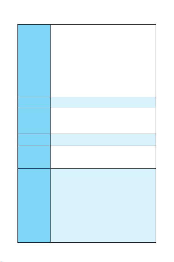
Процессор
Чипсет Intel
Память
Слоты
расширения
Встроенная
графика
Поддержка процессоров Intel® Core™ i3/i5/i7, Intel®
Pentium® и Celeron® 6-го/ 7-го поколения для сокета
LGA1151
®
B250
y 2x DDR4 слота памяти с поддержкой до 32ГБ
Процессоры 7-ого поколения поддерживают DDR4
2400/ 2133 МГц*
Процессоры 6-ого поколения поддерживают DDR4
2133 МГц*
y Двухканальная архитектура памяти
y Поддержка non-ECC, небуферизованной памяти
y Поддержка Intel
* Пожалуйста, обратитесь www.msi.com для получения
дополнительной информации о совместимых
памяти.
** Модули памяти DDR4 будут работать на
максимальной частоте 2400 МГц для процессоров
7-ого поколения и на 2133 М Гц для процессоров
6-ого поколения в режиме XMP.
®
Extreme Memory Profile (XMP)**
y 1x слот PCIe 3.0 x16
y 2x слота PCIe 3.0 x1
y B250M PRO-VH
1x порт VGA, с поддержкой максимального
разрешения 2048×1536@50Гц, 2048×1280@60Гц,
1920×1200@60Гц
1x порт HDMI
разрешения 4096×2160@30Гц (процессоры 7-ого
поколения), 4096×2160@24Гц (процессоры 6-ого
поколения), 2560×1600@60Гц
y B250M PRO-VD
1x порт VGA, с поддержкой максимального
разрешения 2048×1536@50Гц, 2048×1280@60Гц,
1920×1200@60Гц
1x порт DVI-D, с поддержкой максимального
разрешения 1920×1200@60Гц
™
, с поддержкой максимального
Продолжение на следующей странице
3
Продолжение с предыдущей страницы
Чипсет Intel
y 6x портов SATA 6 Гб/с
®
B250
y 1x разъем M.2 (Ключ M)*
Поддержка PCIe 3.0 x4 и SATA 6Гб/с
Подключение
накопителей
USB
Аудио
Поддержка накопителей 2242/ 2260/ 2280
Поддержка Технологии Intel
Поддержка PCIe 3.0 x4 NVMe U.2 SSD с адаптером
Turbo U.2**
* Порт SATA2 будет недоступен при установке модуля
M.2 SATA SSD в разъеме M.2.
** Turbo U.2 адаптер не входит в комплект поставки и
приобретается отдельно.
y Контроллер Intel
6x портов USB 3.1 Gen1 (SuperSpeed USB) (4 порта на
задней панели, 2 порта доступны через внутренние
USB разъемы)
6x портов USB 2.0 (High-speed USB) (2 порта на задней
панели, 4 порта доступны через внутренние USB
разъемы)
y Realtek
®
ALC887 Codec
®
B250
y 7.1-канальный High Definition Audio
®
Optane
™
LAN 1x Гигабитный сетевой контроллер Realtek
y 1x комбинированный порт PS/2 клавиатуры/ мыши
Разъемы
задней панели
y 2x порта USB 2.0
y 1x порт HDMI
y 1x порт DVI-D (для B250M PRO-VD)
y 1x порт VGA
™
(для B250M PRO-VH)
y 1x порт LAN (RJ45)
y 4x порта USB 3.1 Gen1
y 3x аудиоразъема
Продолжение на следующей странице
®
RTL8111H
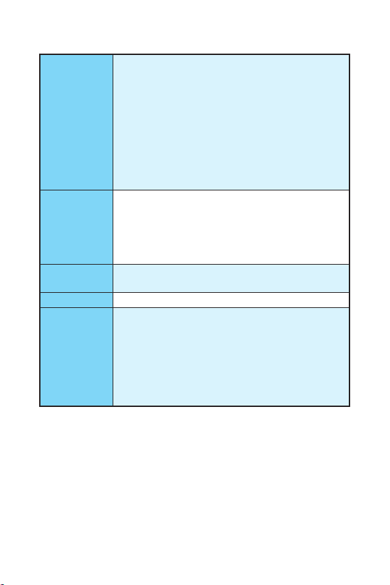
Технические характеристики
4
Разъемы на
плате
Контроллер
ввода-вывода
Аппаратный
мониторинг
Форм-фактор
Параметры
BIOS
Программное
обеспечение
Продолжение с предыдущей страницы
y 1x 24-контактный разъем питания ATX
y 1x 8-контактный разъем питания ATX 12В
y 6x разъемов SATA 6 Гб/с
y 2x разъема USB 2.0 (Поддержка 4-х дополнительных
портов USB 2.0)
y 1x разъем USB 3.1 Gen1 (Поддержка 2-х
дополнительных портов USB 3.1 Gen1)
y 1x 4-контактный разъем вентилятора процессора
y 1x 4-контактный разъем вентилятора системы
y 1x аудиоразъем передней панели
y 2x разъема передней панели
y 1x разъем датчика открытия корпуса
y 1x разъем последовательного порта
y 1x джампер очистки данных CMOS
NUVOTON 5565
y Определение температуры процессора/системы
y Определение скорости вентиляторов процессора/
системы
y Управление скоростью вентиляторов процессора/
системы
y Micro-ATX Форм—фактор
y 8.9 x 7.3 дюйма (22.6 x 18.5 см)
y 1x 64 Мб флэш
y UEFI AMI BIOS
y ACPI 5.0, PnP 1.0a, SM BIOS 2.8
y Мультиязычный интерфейс
y Драйверы
y COMMAND CENTER
y LIVE UPDATE 6
y FAST BOOT
y SUPER CHARGER
y MYSTIC LIGHT
y RAMDISK
y X-BOOST
y MSI SMART TOOL
y NETWORK GENIE
y CPU-Z MSI GAMING
®
Extreme Tuning Utility
y Intel
™
Internet Security Solution
y Norton
y Google Chrome
™
, Google Toolbar, Google Drive
5
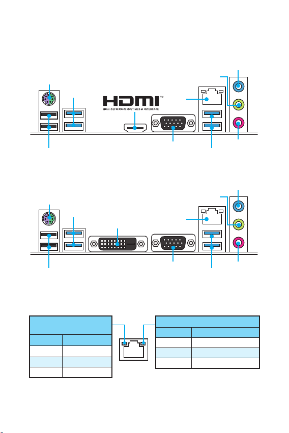
Задняя панель портов ввода/ вывода
B250M PRO-VH
Линейный
VGA
выход
LAN
Микрофонный
USB 3.1 Gen1
Порт PS/2
USB 3.1 Gen1
USB 2.0
B250M PRO-VD
VGA
LAN
Линейный
выход
USB 3.1 Gen1
Микрофонный
Порт PS/2
USB 3.1 Gen1
DVI-D
USB 2.0
Таблица состояний индикатора порта LAN
Подключение/ Работа
индикатора
Состояние Описание
Выкл. Не подключен
Желтый Подключен
Мигает Передача данных
Скорость передачи данных
Состояние Описание
Выкл. 10 Мбит/с подключение
Зеленый 100 Мбит/с подключение
Оранжевый 1 Гбит/с подключение
Линейный
вход
вход
Линейный
вход
вход
Задняя панель портов ввода/ вывода
6
Loading…
- June 9, 2024
- MSI
Table of Contents
- B250M PRO-VH/ B250M PRO-VD Motherboard
- Safety Information
- Specifications
- Rear I/O Panel
- Overview of Components
- Software Description
- Regulatory Notices
- Technical Support
- References
- Read User Manual Online (PDF format)
- Download This Manual (PDF format)
B250M PRO-VH/ B250M PRO-VD Motherboard
User Manual
B250M PRO-VH/ B250M PRO-VD Motherboard
Thank you for purchasing the MSI® B250M PRO-VH/ B250M PRO-VD motherboard. This
User Guide gives information about board layout, component overview and BIOS
setup.
Safety Information
-
The components included in this package are prone to damage from electrostatic discharge (ESD). Please adhere to the following instructions to ensure successful computer assembly.
-
Ensure that all components are securely connected. Loose connections may cause the computer to not recognize a component or fail to start.
-
Hold the motherboard by the edges to avoid touching sensitive components.
-
It is recommended to wear an electrostatic discharge (ESD) wrist strap when
handling the motherboard to prevent electrostatic damage. If an ESD wrist
strap is not available, discharge yourself of static electricity by touching
another metal object before handling the motherboard. -
Store the motherboard in an electrostatic shielding container or on an anti-static pad whenever the motherboard is not installed.
-
Before turning on the computer, ensure that there are no loose screws or metal components on the motherboard or anywhere within the computer case.
-
Do not boot the computer before installation is completed. This could cause permanent damage to the components as well as injury to the user.
-
If you need help during any installation step, please consult a certified computer technician.
-
Always turn off the power supply and unplug the power cord from the power outlet before installing or removing any computer component.
-
Keep this user guide for future reference.
-
Keep this motherboard away from humidity.
-
Make sure that your electrical outlet provides the same voltage as is indicated on the PSU, before connecting the PSU to the electrical outlet.
-
Place the power cord such a way that people can not step on it. Do not place anything over the power cord.
-
All cautions and warnings on the motherboard should be noted.
-
If any of the following situations arises, get the motherboard checked by service personnel:
-
Liquid has penetrated into the computer.
-
The motherboard has been exposed to moisture.
-
The motherboard does not work well or you can not get it work according to user guide.
-
The motherboard has been dropped and damaged.
-
The motherboard has obvious sign of breakage.
-
Do not leave this motherboard in an environment above 60°C (140°F), it may damage the motherboard.
Specifications
CPU| Supports 6th/ 7th Gen Intel® Core™ i3/i5/i7 processors, and Intel®
Pentium® and Celeron® processors for Socket LGA1151
—|—
Chipset| Intel® B250 Chipset
Memory| • 2x DDR4 memory slots, support up to 32GB
• 7th Gen processors support DDR4 2400/ 2133 MHz
• 6th Gen processors support DDR4 2133 MHz
• Dual channel memory architecture
• Supports non-ECC, un-buffered memory
• Supports Intel®
Extreme Memory Profile (XMP)**
- Please refer to www.msi.com for more information on compatible memory.
* DDR4 memory modules can only run at maximum of 2400 MHz for 7th Gen
processors and 2133 MHz for 6 th Gen processors on XMP mode.
Expansion Slots| • 1x PCIe 3.0 x16 slot
• 2x PCIe 3.0 x1 slots
Onboard Graphics| • B250M PRO-VH
• 1x VGA port, supports a maximum resolution of 2048×1536@50Hz,
2048×1280@60Hz, 1920×1200@60Hz
• 1x HDMI™ port, supports a maximum resolution of
4096×2160@30Hz(7th CPU), 4096×2160@24Hz(6th CPU), 2560×1600@60Hz
• B250M PRO-VD
• 1x VGA port, supports a maximum resolution of
2048×1536@50Hz, 2048×1280@60Hz, 1920×1200@60Hz
• 1x DVI-D port, supports a maximum resolution of 1920×1200@60Hz
Storage| Intel B250 Chipset
• 6x SATA 6Gb/s ports
• 1x M.2 slot (Key M)
• Supports up to PCIe 3.0 x4 and SATA 6Gb/s
• Supports 2242/ 2260/ 2280 storage devices
• Intel® OptaneTM Memory Ready
• Support PCIe 3.0 x4 NVMe U.2 SSD with Turbo U.2 Host card** - The SATA2 port will be unavailable when an M.2 SATA SSD module has been installed in the M.2 slot.
** The Turbo U.2 Host Card is not included, please purchase separately.
USB| •Intel® B250 Chipset
•6x USB 3.1 Gen1 (SuperSpeed USB) ports (4 ports on the back panel, 2 ports
available through the internal USB connector)
•6x USB 2.0 (High-speed USB) ports (2 ports on the back panel, 4 ports
available through the internal USB connectors)
—|—
Audio| •Realtek® ALC887 Codec
•7.1-Channel High Definition Audio
LAN| in Rea ltek® RTL8111H Gigabit LAN controller
Back Panel Connectors| •lx PS/2 keyborard/ mouse combo port
•2x USB 2.0 ports
•to HDMI” port (for B250M PRO-VH)
•to DVI-D port (for B250M PRO-VD)
•lx VGA port
•to LAN (RJ45) port
•4x USB 3.1 Gent ports
•3x audio jacks
Internal Connectors| •in 24-pin ATX main power connector
•1x 8-pin ATX 12V power connector
•6x SATA 6Gb/s connectors
•2x USB 2.0 connectors (supports additional 4 USB 2.0 ports)
•in USB 3.1 Gen1 connector (supports additional 2 USB 3.1 Gent ports)
•to 4-pin CPU fan connector
•to 4-pin system fan connector
•1x Front panel audio connector
•2x Front panel connectors
•to Chassis Intrusion connector
•to Serial Port connector
•1x Clear CMOS jumper
I/O Controller-| NUVOTON 5565 Controller Chip
Hardware Monitor| •CPU/System temperature detection
•CPU/System fan speed detection
•CPU/System fan speed control
Form Factor-| •Micro-ATX Form Factor
•8.9 in. x 7.3 in. (22.6 cm x 18.5 cm)
BIOS Features| • 1x 64 Mb flash
• UEFI AMI BIOS
• ACPI 5.0, PnP 1.0a, SM BIOS 2.8
• Multi-language
—|—
Software| • Drivers
• COMMAND CENTER
• LIVE UPDATE 6
• FAST BOOT
• SUPER CHARGER
• MYSTIC LIGHT
•RAMDISK
• X-BOOST
• MSI SMART TOOL
• NETWORK GENIE
• CPU-Z MSI GAMING
• Intel® Extreme Tuning Utility
• Norton™ Internet Security Solution
• Google Chrome™, Google Toolbar, Google Drive
Rear I/O Panel
B250M PRO-VH B250M PRO-VD
LAN Port LED Status Table
| Link/ Activity LED | Speed LED | |
|---|---|---|
| Status | Description | |
| Off | No link | Off |
| Yellow | Linked | Green |
| Blinking | Data activity | Orange |
Overview of Components
CPU Socket
Please install the CPU into the CPU socket as shown below.
**Important**
- Always unplug the power cord from the power outlet before installing or removing the CPU.
- Please retain the CPU protective cap after installing the processor. MSI will deal with Return Merchandise Authorization (RMA) requests if only the motherboard comes with the protective cap on the CPU socket.
- When installing a CPU, always remember to install a CPU heatsink. A CPU heatsink is necessary to prevent overheating and maintain system stability.
- Confirm that the CPU heatsink has formed a tight seal with the CPU before booting your system.
- Overheating can seriously damage the CPU and motherboard. Always make sure the cooling fans work properly to protect the CPU from overheating. Be sure to apply an even layer of thermal paste (or thermal tape) between the CPU and the heatsink to enhance heat dissipation.
- Whenever the CPU is not installed, always protect the CPU socket pins by covering the socket with the plastic cap.
- If you purchased a separate CPU and heatsink/ cooler, Please refer to the documentation in the heatsink/ cooler package for more details about installation.
DIMM Slots
Please install the memory module into the DIMM slot as shown below.
**Important**
- Due to chipset resource usage, the available capacity of memory will be a little less than the amount of installed.
- Please note that the maximum capacity of addressable memory is 4GB or less for 32-bit Windows OS due to the memory address limitation. Therefore, we recommended that you to install 64-bit Windows OS if you want to install more than 4GB memory on the motherboard.
PCI_E1~E3: PCIe Expansion Slot
**Important**
- When adding or removing expansion cards, always turn off the power supply and unplug the power supply power cable from the power outlet. Read the expansion card’s documentation to check for any necessary additional hardware or software changes.
- If you install a large and heavy graphics card, you need to use a tool such as MSI Gaming Series Graphics Card Bolster to support its weight to prevent deformation of the slot.
SATA1~6: SATA 6Gb/s Connectors
These connectors are SATA 6Gb/s interface ports. Each connector can connect to
one SATA device. **Important**
- Please do not fold the SATA cable at a 90-degree angle. Data loss may result during transmission otherwise.
- SATA cable has identical plugs on either sides of the cable. However, it is recommended that the flat connector be connected to the motherboard for space saving purposes.
M2_1: M.2 Slot (Key M)
Please install the M.2 solid-state drive (SSD) into the M.2 slot as shown
below. **Important
Intel® RST only supports PCIe M.2 SSD with UEFI ROM, does not support Legacy
ROM.
ATX_PWR1, CPU_PWR1: Power Connectors**
These connectors allow you to connect an ATX power supply.
| 1| +3.3V| 13| +3.3V
—|—|—|—|—
2| +3.3V| 14| -12V
3| Ground| 15| Ground
4| +5V| 16| PS-ON#
5| Ground| 17| Ground
6| +5V| 18| Ground
7| Ground| 19| Ground
8| PWR OK| 20| Res
9| 5VSB| 21| +5V
10| +12V| 22| +5V
11| +12V| 23| +5V
12| +3.3V| 24| Ground
| 1| Ground| 5| +12V
—|—|—|—|—
2| Ground| 6| +12V
3| Ground| 7| +12V
4| Ground| 8| +12V
Important
Make sure that all the power cables are securely connected to a proper ATX
power supply to ensure stable operation of the motherboard.
JCOM1: Serial Port Connector
This connector allows you to connect the optional serial port with bracket.
| 1| DCD| 2| SIN
—|—|—|—|—
3| SOUT| 4| DTR
5| Ground| 6| DSR
7| RTS| 8| CTS
9| RI| 10| No Pin
JFP1, JFP2: Front Panel Connectors
These connectors connect to the switches and LEDs on the front panel.
| 1| HDD LED +| 2| Power LED +
—|—|—|—|—
3| HDD LED –| 4| Power LED –
5| Reset Switch| 6| Power Switch
7| Reset Switch| 8| Power Switch
9| Reserved| 10| No Pin
| 1| Speaker –| 2| Buzzer +
—|—|—|—|—
3| Buzzer –| 4| Speaker +
JUSB1~2: USB 2.0 Connectors
These connectors allow you to connect USB 2.0 ports on the front panel.
| 1| VCC| 2| VCC
—|—|—|—|—
3| USB0-| 4| USB1-
5| USB0+| 6| USB1+
7| Ground| 8| Ground
9| No Pin| 10| NC
JUSB3: USB 3.1 Gen1 Connector
This connector allows you to connect USB 3.1 Gen1 ports on the front panel.
| 1| Power| 11| USB2.0+
—|—|—|—|—
2| USB3_RX_DN| 12| USB2.0-
3| USB3_RX_DP| 13| Ground
4| Ground| 14| USB3_TX_C_DP
5| USB3_TX_C_DN| 15| USB3_TX_C_DN
6| USB3_TX_C_DP| 16| Ground
7| Ground| 17| USB3_RX_DP
8| USB2.0-| 18| USB3_RX_DN
9| USB2.0+| 19| Power
10| NC| 20| No Pin
**Important**
- Note that the VCC and Ground pins must be connected correctly to avoid possible damage.
- In order to recharge your iPad,iPhone and iPod through USB ports, please install MSI® SUPER CHARGER utility.
JAUD1: Front Audio Connector
This connector allow you to connect audio jacks on the front panel.
| 1| MIC L| 2| Ground
—|—|—|—|—
3| MIC R| 4| NC
5| Head Phone R| 6| MIC Detection
7| SENSE_SEND| 8| No Pin
9| Head Phone L| 10| Head Phone Detection
CPU_FAN1, SYS_FAN1: Fan Connectors
Fan connectors can be classified as PWM (Pulse Width Modulation) Mode and DC
Mode. PWM Mode fan connectors provide constant 12V output and adjust fan speed
with speed control signal. DC Mode fan connectors control fan speed by
changing voltage. When you plug a 3-pin (Non-PWM) fan to a PWM Mode fan
connector, the fan speed will be always maintained at 100%, and that could be
noisy.
Default PWM Mode fan connector
1| Ground| 2| +12V
3| Sense Signal| 4| Speed Control
1| Ground| 2| Voltage Control
3| Sense| 4| NC
Switching fan mode and adjusting fan speed
You can switch between PWM mode and DC mode, and adjust fan speed in BIOS >
Advanced > Hardware Monitor. In Hardware Monitor menu, you can set the
temperature levels and the corresponding fan speed levels.
Important
Make sure fans are working properly after switching the PWM/ DC mode.
JCI1: Chassis Intrusion Connector
This connector allows you to connect the chassis intrusion switch cable.
Normal (default) Trigger the chassis intrusion event
Using chassis intrusion detector
- Connect the JCI1 connector to the chassis intrusion switch/ sensor on the chassis.
- Close the chassis cover.
- Go to BIOS > Security > Chassis Intrusion Configuration.
- Set Chassis Intrusion to Enabled.
- Press F10 to save and exit and then press the Enter key to select Yes.
- Once the chassis cover is opened again, a warning message will be displayed on screen when the computer is turned on.
Keep Data (default) Clear CMOS/ Reset BIOS
Resetting BIOS to default values
- Power off the computer and unplug the power cord
- Use a jumper cap to short JBAT1 for about 5-10 seconds.
- Remove the jumper cap from JBAT1.
- Plug the power cord and power on the computer.
EZ Debug LED: Debug LED indicators
These LEDs indicate the status of key components during booting process. When
an error is occurred, the corresponding LED stays lit until the problem is
solved.
CPU – indicates CPU is not detected or fail.
DRAM – indicates DRAM is not detected or fail.
VGA – indicates GPU is not detected or fail.
BOOT – indicates booting device is not detected or fail.
BIOS Setup
The default settings offer the optimal performance for system stability in
normal conditions. You should always keep the default settings to avoid
possible system damage or failure booting unless you are familiar with BIOS.
**Important**
-
BIOS items are continuous update for better system performance. Therefore, the description may be slightly different from the latest BIOS and should be held for reference only. You could also refer to the HELP information panel for BIOS item description.
-
The pictures in this chapter are for reference only and may vary from the product you purchased.
Entering BIOS Setup
Please refer the following methods to enter BIOS setup. -
Press Delete key, when the Press DEL key to enter Setup Menu, F11 to enter Boot Menu message appears on the screen during the boot process.
-
Use MSI FAST BOOT application. Click on GO2BIOS button and choose OK. The system will reboot and enter BIOS setup directly.
Function key
| Key | Function | Key | Function |
|---|---|---|---|
| F1 | General Help | F4 | Enter CPU Specifications menu |
| F5 | Enter Memory-Z menu | F6 | Load optimized defaults |
| F10 | Save Change and Reset* | F12 | Take a screenshot and save it to USB flash |
drive (FAT/ FAT32 format only).
-
When you press F10, a confirmation window which provides the modification information appears. Select between Yes or No to confirm your choice.
Resetting BIOS
You might need to restore the default BIOS setting to solve certain problems.
There are several ways to reset BIOS:- Go to BIOS and press F6 to load optimized defaults.
- Short the Clear CMOS jumper on the motherboard.
Important
Please refer to the Clear CMOS Jumper section for resetting BIOS.
Updating BIOS
Updating BIOS with M-FLASH Before updating: Please download the latest BIOS
file that matches your motherboard model from MSI website. And then save the
BIOS file into the USB flash drive. Updating BIOS:
- Insert the USB flash drive that contains the update file into the computer.
- Reboot the system, and then press Del key to enter the BIOS Setup during POST.
- Go to BIOS > M-FLASH > Select one file to update BIOS and ME, select a BIOS file to perform the BIOS update process.
- After the flashing process is 100% complete, the system will reboot.
Updating the BIOS with Live Update 6
Before updating:
Make sure the LAN driver is already installed and the internet connection is
set properly.
Updating BIOS:
- Install and launch MSI LIVE UPDATE 6.
- Select Manual scan.
- Check MB BIOS box and click on Scan button.
- Select the MB BIOS and click on icon to download and install the latest BIOS file.
- Click Next and choose In Windows mode. And then click Next and Start to start updating BIOS.
- After the flashing process is 100% completed, the system will restart automatically.
Software Description
Installing Windows® 7/ 8.1/ 10
-
Power on the computer.
-
Insert the Windows ® 7/ 8.1/ 10 disc into your optical drive.
Note: Due to chipset limitation, during the Windows ® 7 installation
process, USB optical drives and USB pen drives are not supported. You can use
MSI Smart Tool to install Windows® 7. -
Press the Restart button on the computer case.
-
For windows® 8.1/ 10, skip this step. For Windows®7, access the BIOS menu Advanced > Windows OS Configuration > Windows 7 Installation and set the item to enabled, save changes and restart.
Note: It is suggested to plug in your USB Keyboard/USB Mouse to the
leftmost USB port when installing Windows®7. -
Press F11 key during the computer POST (Power-On Self Test) to get into Boot Menu.
-
Select your optical drive from the Boot Menu.
-
Press any key when screen shows Press any key to boot from CD or DVD… message.
-
Follow the instructions on the screen to install Windows ® 7/ 8.1/ 10.
Installing Drivers
- Start up your computer in Windows® 7/ 8.1/ 10.
- Insert MSI® Driver Disc into your optical drive.
- The installer will automatically appear and it will find and list all necessary drivers.
- Click Install button.
- The software installation will then be in progress, after it has finished it will prompt you to restart.
- Click OK button to finish.
- Restart your computer.
Installing Utilities
Before you install utilities, you must complete drivers installation.
- Insert MSI® Driver Disc into your optical drive.
- The installer will automatically appear.
- Click Utilities tab.
- Select the utilities you want to install.
- Click Install button.
- The utilities installation will then be in progress, after it has finished it will prompt you to restart.
- Click OK button to finish.
- Restart your computer.
Regulatory Notices
FCC Compliance Statement
Note: This equipment has been tested and found to comply with the limits
for a Class B digital device, pursuant to part 15 of the FCC Rules.
These limits are designed to provide reasonable protection against harmful
interference in a residential installation. This equipment generates, uses and
can radiate radio frequency energy and, if not installed and used in
accordance with the instructions, may cause harmful interference to radio
communications.
However, there is no guarantee that interference will not occur in a
particular installation. If this equipment does cause harmful interference to
radio or television reception, which can be determined by turning the
equipment off and on, the user is encouraged to try to correct the
interference by one or more of the following measures:
- Reorient or relocate the receiving antenna.
- Increase the separation between the equipment and receiver.
- Connect the equipment into an outlet on a circuit different from that to which the receiver is connected.
- Consult the dealer or an experienced radio/TV technician for help.
Caution: Changes or modifications not expressly approved by the party
responsible for compliance could void the user’s authority to operate the
equipment.
Tested to comply with FCC standards FOR HOME OR OFFICE USE
This device complies with part 15 of the FCC Rules. Operation is subject to
the following two conditions:
(1) This device may not cause harmful interference, and (2) this device must
accept any interference received, including interference that may cause
undesired operation.
CE Conformity
** Hereby, Micro-Star International CO., LTD declares that this device is
in compliance with the essential safety requirements and other relevant
provisions set out in the European Directive.
C-Tick Compliancec
N1996
Battery Information European Union:
** Batteries, battery packs, and accumulators should not be disposed of as
unsorted household waste. Please use the public collection system to return,
recycle, or treat them in compliance with the local regulations.
Taiwan:
For better environmental protection, waste batteries should be
collectedseparately for recycling or special disposal.
California, USA:
** The button cell battery may contain perchlorate material and requires
special handling when recycled or disposed of in California.
For further information please visit:
http://www.dtsc.ca.gov/hazardouswaste/perchlorate/
CAUTION: There is a risk of explosion, if battery is incorrectly replaced.
Replace only with the same or equivalent type recommended by the manufacturer.
Chemical Substances Information
In compliance with chemical substances regulations, such as the EU REACH
Regulation (Regulation EC No. 1907/2006 of the European Parliament and the
Council), MSI provides the information of chemical substances in products at:
http://www.msi.com/html/popup/csr/evmtprtt_pcm.html
WEEE (Waste Electrical and Electronic Equipment) Statement
To protect the global environment and as an environmentalist, MSI must remind
you that… Under the European Union (“EU”) Directive on Waste Electrical and
Electronic Equipment, Directive 2002/96/EC, which takes effect on August 13,
2005, products of “electrical and electronic equipment” cannot be discarded as
municipal wastes anymore, and manufacturers of covered electronic equipment
will be obligated to take back such products at the end of their useful life.
MSI will comply with the product take back requirements at the end of life of
MSI-branded products that are sold into the EU. You can return these products
to local collection points.
Environmental Policy**
- The product has been designed to enable proper reuse of parts and recycling and should not be thrown away at its end of life.
- Users should contact the local authorized point of collection for recycling and disposing of their end-of-life products.
- Visit the MSI website and locate a nearby distributor for further recycling information.
Users may also reach us at gpcontdev@msi.com for
information regarding proper Disposal, Take-back, Recycling, and Disassembly
of MSI products.
Copyright
Micro-Star Int’l Co.,Ltd.
Copyright © 2016 All rights reserved.
The material in this document is the intellectual property of Micro-Star Int’l
Co.,Ltd. We take every care in the preparation of this document, but no
guarantee is given as to the correctness of its contents. Our products are
under continual improvement and we reserve the right to make changes without
notice.
Technical Support
If a problem arises with your system and no solution can be obtained from the
user guide, please contact your place of purchase or local distributor.
Alternatively, please try the following help resources for further guidance.
- Visit the MSI website for technical guide, BIOS updates, driver updates, and other information: http://www.msi.com
- Register your product at: http://register.msi.com
Trademark Recognition
All product names used in this manual are the properties of their respective
owners and are acknowledged.
Revision History
Version 1.0, 2016/11, First release.
References
- MSI — Redirect
- dtsc.ca.gov/hazardouswaste/
- MSI — Redirect
- csr
Read User Manual Online (PDF format)
Read User Manual Online (PDF format) >>
Download This Manual (PDF format)
Download this manual >>
MSI B250M Pro-VH, B250M Pro-VD Quick Start Guide
MSI B250M Pro-VH, B250M Pro-VD Specification
The MSI B250M Pro-VH and B250M Pro-VD are micro-ATX motherboards designed for Intel’s 6th and 7th generation processors, supporting the LGA 1151 socket. Both motherboards are built on the Intel B250 chipset, offering a robust platform for business and home computing needs. They support dual-channel DDR4 memory, with a maximum capacity of 32GB across two DIMM slots, ensuring efficient multitasking and performance. The boards are equipped with a variety of connectivity options, including a PCIe 3.0 x16 slot for graphics card expansion, along with two PCIe 3.0 x1 slots for additional peripherals. Storage solutions are versatile, featuring four SATA 6Gb/s ports for HDDs and SSDs.
Audio is managed by the Realtek ALC887 codec, delivering high-definition sound quality suitable for most user needs. Networking is handled by a Realtek 8111H Gigabit LAN controller, ensuring reliable and fast internet connectivity. Display outputs include HDMI and VGA ports, allowing for flexible monitor configurations. The rear I/O panel includes a mix of USB 3.1 Gen1 and USB 2.0 ports, catering to a wide array of peripheral connections. Additionally, the boards support MSI’s signature features like Military Class 5 components for durability, Guard-Pro for system protection, and Click BIOS 5 for intuitive system management.
Both models are designed to offer a stable and efficient foundation for a range of computing tasks, with the Pro-VH variant including a DVI-D port for additional display output flexibility. These motherboards are ideal for users seeking reliability and essential features without the need for high-end gaming or overclocking capabilities.
To update the BIOS, visit the MSI support website, download the latest BIOS update for your model, extract the files to a USB drive formatted in FAT32, and then enter the BIOS setup by pressing ‘DEL’ during boot. Use the M-Flash utility in the BIOS to select the BIOS file on your USB drive and follow the prompts to update.
The MSI B250M Pro-VD motherboard supports a maximum of 32GB of DDR4 RAM, with two DIMM slots supporting up to 16GB in each slot.
To reset the CMOS, power off your system and unplug it. Locate the CMOS battery on the motherboard and remove it for about 5-10 minutes. Alternatively, you can use the jumper method by moving the jumper from the default position 1-2 to 2-3 for a few seconds, then return it to 1-2. Power on your system to reset the BIOS settings.
First, ensure all cables and components are securely connected. Check for any visible damage or loose components. If the problem persists, try resetting the CMOS. If still unresolved, remove all peripherals and test the system with minimal hardware. If the issue continues, consider seeking professional repair services.
To enable XMP, enter the BIOS setup by pressing ‘DEL’ during boot. Navigate to the ‘OC’ or ‘Overclocking’ section and find the XMP Profile option. Set it to Profile 1 or the desired profile based on your RAM specification. Save the changes and exit the BIOS.
The MSI B250M Pro-VD motherboard includes one PCIe 3.0 x16 slot for graphics cards and two PCIe 3.0 x1 slots for additional expansion cards.
Refer to the motherboard manual for the pin layout. Typically, the front panel connectors, including power switch, reset switch, HDD LED, and power LED, are located at the bottom right corner of the motherboard. Plug them into the corresponding pins on the front panel header.
Visit the MSI support website and navigate to the CPU compatibility section for the B250M Pro-VD model. Enter your CPU model number to check compatibility. Ensure your BIOS version supports the CPU, updating it if necessary.
The MSI B250M Pro-VH motherboard supports four SATA III ports for traditional HDDs and SSDs, as well as an M.2 slot for NVMe SSDs, providing flexible storage expansion options.
Ensure that the CPU cooler is properly seated and functioning. Verify that all case fans are operational and correctly positioned for optimal airflow. Clean any dust from the heatsinks and fans. Consider reapplying thermal paste if necessary. Ensure the case has adequate ventilation.
1
<變數 1> Contents
Contents
Safety Information ………………………………………………………………………………. 2
Specifications ………………………………………………………………………………………3
Rear I/O Panel …………………………………………………………………………………….6
B250M PRO-VH ……………………………………………………………………………………..6
B250M PRO-VD ……………………………………………………………………………………..6
LAN Port LED Status Table ……………………………………………………………………..6
Overview of Components ……………………………………………………………………..7
CPU Socket ……………………………………………………………………………………………8
DIMM Slots ……………………………………………………………………………………………9
PCI_E1~E3: PCIe Expansion Slot ……………………………………………………………..9
SATA1~6: SATA 6Gb/s Connectors ………………………………………………………….10
M2_1: M.2 Slot (Key M) ………………………………………………………………………….10
ATX_PWR1, CPU_PWR1: Power Connectors ……………………………………………11
JCOM1: Serial Port Connector ……………………………………………………………….11
JFP1, JFP2: Front Panel Connectors ………………………………………………………12
JUSB1~2: USB 2.0 Connectors ………………………………………………………………12
JUSB3: USB 3.1 Gen1 Connector ……………………………………………………………13
JAUD1: Front Audio Connector ………………………………………………………………13
CPU_FAN1, SYS_FAN1: Fan Connectors …………………………………………………14
JCI1: Chassis Intrusion Connector …………………………………………………………15
JBAT1: Clear CMOS (Reset BIOS) Jumper ……………………………………………….15
EZ Debug LED: Debug LED indicators ……………………………………………………15
BIOS Setup ……………………………………………………………………………………….. 16
Entering BIOS Setup……………………………………………………………………………..16
Resetting BIOS …………………………………………………………………………………….17
Updating BIOS ……………………………………………………………………………………..17
Software Description ………………………………………………………………………….18
Installing Windows
®
7/ 8.1/ 10 ……………………………………………………………….18
Installing Drivers ………………………………………………………………………………….18
Installing Utilities …………………………………………………………………………………18
Thank you for purchasing the MSI
®
B250M PRO-VH/ B250M
PRO-VD motherboard. This User Guide gives information
about board layout, component overview and BIOS setup.
MSI B250M PRO-VD User Manual
Благодарим Вас за покупку материнской платы MSI ®
B250M PRO-VH/ B250M PRO-VD . Данное руководство пользователя содержит информацию о схеме платы, компонентах материнской платы и настройке BIOS.
Таблица состояний индикатора порта LAN.
E3: Слоты расширения PCIe .
6: Разъемы SATA 6 Гб/с.
M2_1: Разъем M.2 (Ключ M) .
Разъем последовательного порта.
JFP1, JFP2: Разъемы передней панели.
2: Разъемы USB 2.0 .
Разъем USB 3.1 Gen1.
Разъем аудио передней панели.
CPU_FAN1, SYS_FAN1: Разъемы вентиляторов.
JCI1: Разъем датчика открытия корпуса.
JBAT1: Джампер очистки данных CMOS (Сброс BIOS).
EZ Debug LED: Индикаторы отладки.
Вход в настройки BIOS.
Установка Windows 7/ 8.1/ 10.
y Компоненты, входящие в комплект поставки могут быть повреждены статическим электричеством. Для успешной сборки компьютера, пожалуйста, следуйте указаниям ниже.
y Убедитесь, что все компоненты компьютера подключены должным образом. Ослабленные соединения компонентов могут привести как к сбоям в работе, так и полной неработоспособности компьютера.
y Чтобы избежать повреждений компонентов платы всегда держите ее за края.
y При сборке комьютера рекомендуется пользоваться электростатическим браслетом. В случае, если это невозможно, перед работой с платой снимите электростатический заряд со своего тела, прикоснувшись к металлическому предмету.
y В случае, если материнская плата не установлена в корпус, храните ее в антистатической упаковке или на антистатическом коврике.
y Перед включением компьютера убедитесь, что все винты крепления и другие металлические компоненты на материнской плате и внутри корпуса надежно зафиксированы.
y Не включайте компьютер, если сборка не завершена. Это может привести к повреждению компонентов, а также травмированию пользователя.
y Если вам нужна помощь на любом этапе сборки компьютера, пожалуйста, обратитесь к сертифицированному компьютерному специалисту.
y Всегда выключайте питание и отсоединяйте шнур питания от электрической розетки перед установкой или удалением любого компонента компьютера.
y Сохраните это руководство для справки.
y Не допускайте воздействия на материнскаую плату высокой влажности. y Перед тем как подключить блок питания компьютера к электрической розетке убедитесь, что напряжение электросети соответствует напряжению, указанному на блоке питания.
y Располагайте шнур питания так, чтобы на него не могли наступить люди. Не ставьте на шнур питания никаких предметов.
y Необходимо учитывать все предостережения и предупреждения, указанные на материнской плате.
y При возникновении любой из перечисленных ниже ситуаций обратитесь в сервисный центр для проверки материнской платы:
Попадание жидкости внутрь компьютера.
Материнская плата подверглась воздействию влаги.
Материнская плата не работает должным образом или невозможно наладить ее работу в соответствии с руководством пользователя.Материнская плата получила повреждения при падении.
Материнская плата имеет явные признаки повреждения.
y Не храните материнскую плату в местах с температурой выше 60 °C (140 °F), так как это может привести к ее повреждению.
Источник