

1
Contents
Contents
2
3
8
9
CPU Socket …………………………………………………………………………………………………10
DIMM Slots………………………………………………………………………………………………….11
DIMM Slots………………………………………………………………………………………………….11
PCI_E1~3: PCIe Expansion Slots ……………………………………………………………………11
JFP1, JFP2: Front Panel Connectors ……………………………………………………………..12
JAUD1: Front Audio Connector ……………………………………………………………………..12
SATA1~6: SATA 6Gb/s Connectors …………………………………………………………………13
M2_1: M.2 Slot (Key M) …………………………………………………………………………………13
ATX_PWR1, CPU_PWR1: Power Connectors …………………………………………………..14
JUSB1~2: USB 2.0 Connectors ………………………………………………………………………15
JUSB3: USB 3.2 Gen 1 5Gbps Connector ………………………………………………………..15
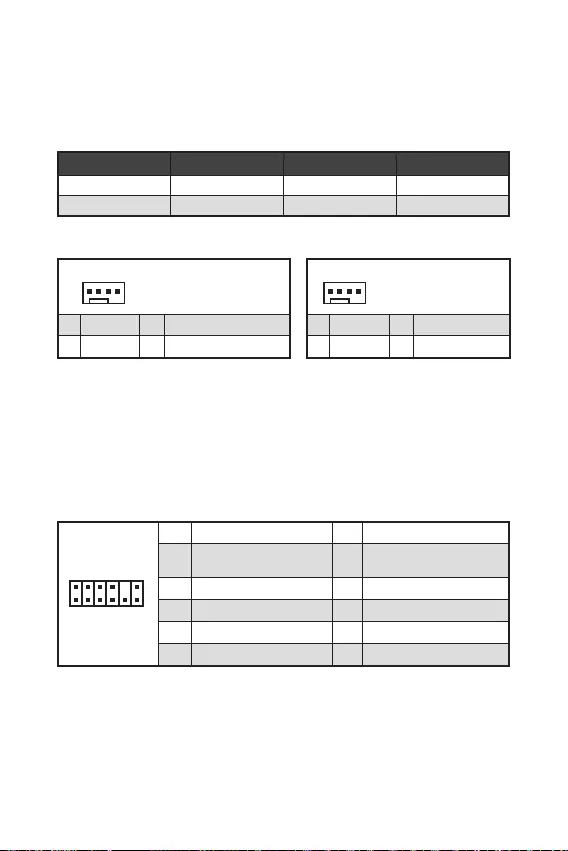
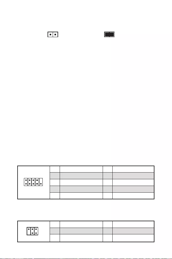
CPU_FAN1, SYS_FAN1: Fan Connectors ………………………………………………………..16
JTPM1: TPM Module Connector …………………………………………………………………….16
JCI1: Chassis Intrusion Connector …………………………………………………………………17
JCOM1: Serial Port Connector ………………………………………………………………………17
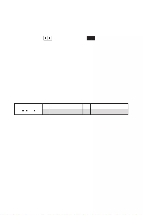
JDASH1: Tuning controller Connector ……………………………………………………………17
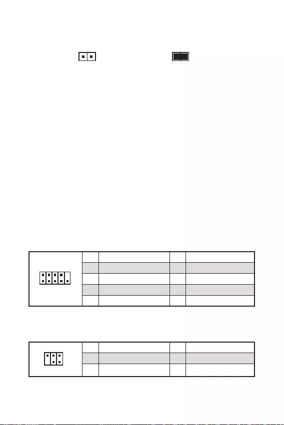
JBAT1: Clear CMOS (Reset BIOS) Jumper ………………………………………………………18
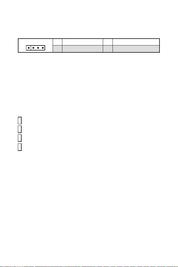
JRAINBOW1: Addressable RGB LED connectors …………………………………………….18
JRGB1: RGB LED connector ………………………………………………………………………….19
EZ Debug LED …………………………………………………………………………………………….19
20
21
BIOS Setup ………………………………………………………………………………………………….22
Entering BIOS Setup …………………………………………………………………………………….22
BIOS User Guide ………………………………………………………………………………………….22
Resetting BIOS …………………………………………………………………………………………….23
Updating BIOS……………………………………………………………………………………………..23
Thank you for purchasing the MSI®
motherboard. This User Guide gives
information about board layout, component overview, BIOS
setup and software installation.

2
The components included in this package are prone to damage from electrostatic
discharge (ESD). Please adhere to the following instructions to ensure successful
computer assembly.
Ensure that all components are securely connected. Loose connections may cause
the computer to not recognize a component or fail to start.
Hold the motherboard by the edges to avoid touching sensitive components.
It is recommended to wear an electrostatic discharge (ESD) wrist strap when
handling the motherboard to prevent electrostatic damage. If an ESD wrist strap is
not available, discharge yourself of static electricity by touching another metal object
before handling the motherboard.
Store the motherboard in an electrostatic shielding container or on an anti-static
pad whenever the motherboard is not installed.
Before turning on the computer, ensure that there are no loose screws or metal
components on the motherboard or anywhere within the computer case.
Do not boot the computer before installation is completed. This could cause
permanent damage to the components as well as injury to the user.
If you need help during any installation step, please consult a certified computer
technician.
Always turn off the power supply and unplug the power cord from the power outlet
before installing or removing any computer component.
Keep this user guide for future reference.
Keep this motherboard away from humidity.
Make sure that your electrical outlet provides the same voltage as is indicated on
the PSU, before connecting the PSU to the electrical outlet.
Place the power cord such a way that people can not step on it. Do not place
anything over the power cord.
All cautions and warnings on the motherboard should be noted.
If any of the following situations arises, get the motherboard checked by service
personnel:
Liquid has penetrated into the computer.
The motherboard has been exposed to moisture.
The motherboard does not work well or you can not get it work according to
user guide.
The motherboard has been dropped and damaged.
The motherboard has obvious sign of breakage.
Do not leave this motherboard in an environment above 60°C (140°F), it may
damage the motherboard.

3
Supports 10th Gen Intel® Core™ Processors, 11th Gen Intel®
Core™ Processors, Pentium® Gold and Celeron® Processors*
Processor socket LGA1200
* Please go to intel.com for compatibility information
Intel® B560 chipset
2x DDR4 memory slots, support up to 64GB*
Supports 1R 2133/ 2666/ 2933 MHz for 10th Gen Intel® CPU
(by JEDEC & POR)
Supports 1R 2133/ 2666/ 2933/ 3200 MHz for 11th Gen Intel®
CPU (by JEDEC & POR)
Max overclocking frequency:
1DPC 1R Max speed up to 5200 MHz
1DPC 2R Max speed up to 4700+ MHz
Supports Dual-Channel mode
Supports non-ECC, un-buffered memory
Supports Intel® Extreme Memory Profile (XMP)
* Please refer www.msi.com for more information on
compatible memory.
1x PCIe x16 slot (From CPU)
Support up to PCIe 4.0 for 11th Gen Intel® CPU
Support up to PCIe 3.0 for 10th Gen Intel® CPU
2x PCIe 3.0 x1 slots (From B560 chpiset)
1x VGA port, supports a maximum resolution of 2048×1536
@50Hz, 2048×1280 @60Hz, 1920×1200 @60Hz*/**
1x DisplayPort 1.4 port, supports a maximum resolution of
4K 60Hz*/** (For B560M PRO only)
1x HDMI 2.0b with HDR port, supports a maximum
resolution of 4K 60Hz*/**
* Available only on processors featuring integrated graphics.
** Graphics specifications may vary depending on the CPU
installed.
Continued on next page

4
Continued from previous page
6x SATA 6Gb/s ports (From B560 chipset)
1x M.2 slot (Key M)*
Supports up to PCIe 4.0×4 (From CPU)
Available on 11th Gen Intel® CPU
Supports PCIe 3.0×4 (From B560 chipset)
Supports 2242/ 2260/ 2280 storage devices
Supports Intel® Smart Response Technology for Intel Core™
processors
Intel® B560 Chipset
6x USB 2.0 ports (2 Type-A port on the back panel, 4
ports available through internal USB 2.0 connectors)
6x USB 3.2 Gen 1 5Gbps ports (4 Type-A ports on the
back panel, 2 ports available through internal USB 3.2
Gen1 connector)
Realtek® ALC897 Codec
7.1-Channel High Definition Audio
1x Realtek® 8125B 2.5Gbps LAN controller
Continued on next page

Continued from previous page
1x 24-pin ATX main power connector
1x 8-pin ATX 12V power connector
6x SATA 6Gb/s connectors
1x M.2 slot (M-Key)
1x USB 3.2 Gen 1 5Gbps connector (supports additional 2
USB 3.2 Gen 1 5Gbps ports)
2x USB 2.0 connectors (supports additional 4 USB 2.0 ports)
1x 4-pin CPU fan connector
1x 4-pin system fan connector
1x Front panel audio connector
2x System panel connectors
1x Chassis Intrusion connector
1x Clear CMOS jumper
1x TPM module connector
1x Serial port connector
1x Tuning Controller Connector
1x 4-pin RGB LED connector (For B560M PRO & B560M
BOMBER)
1x 3-pin RAINBOW LED connector (For B560M PRO &
B560M BOMBER)
4x EZ Debug LED
1x HDMI port
1x VGA port
1x DisplayPort (For B560M PRO only)
1x PS/2 keyboard/ mouse combo port
2x USB 2.0 Type-A ports
4x USB 3.2 Gen1 5Gbps Type-A ports
1x LAN (RJ45) port
3x audio jacks
Continued on next page

Continued from previous page
NUVOTON NCT6687-R Controller Chip
CPU/ System/ Chipset temperature detection
CPU/ System/ Pump fan speed detection
CPU/ System/ Pump fan speed control
Micro-ATX Form Factor
9.3 in. x 8.0 in. (23.6 cm x 20.2 cm)
1x 256 Mb flash
UEFI AMI BIOS
ACPI 6.2, SMBIOS 3.0
Multi-language
Drivers
MSI Center
Intel® Extreme Tuning Utility
CPU-Z MSI GAMING
Google Chrome™, Google Toolbar, Google Drive
Norton™ Internet Security Solution
Mystic Light (For B560M PRO & B560M BOMBER)
LAN Manager
User Scenario
Hardware Monitor
Frozr AI Cooking
True Color
Live Update
Speed Up
Super Charger
Continued on next page

7
Continued from previous page
Audio
Audio Boost
Network
2.5G LAN
LAN Manager
Cooling
1x M.2 Shield Frozr
Smart Fan Control
LED
Mystic Light Extension (RAINBOW/RGB) (For B560M
PRO & B560M BOMBER)
Mystic Light SYNC
EZ DEBUG LED
Performance
DDR4 Boost
Core Boost
USB3.2 Gen1 5G
USB with Type A
Front USB Type-A
Protection
PCI-E Steel Armor
Experience
Click BIOS 5
8
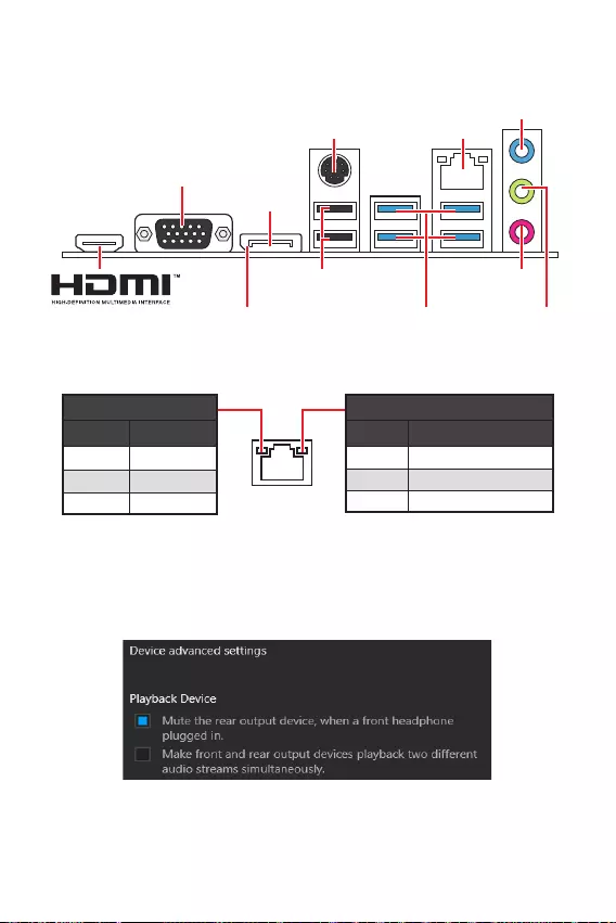
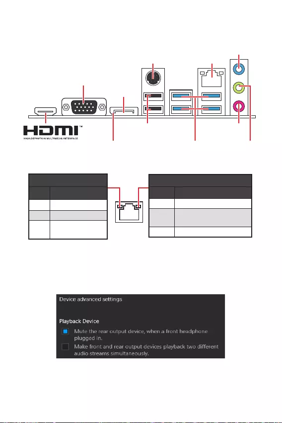
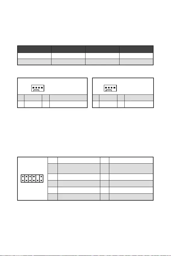
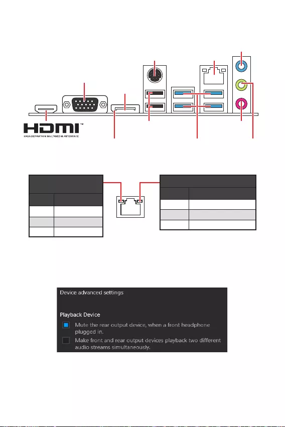
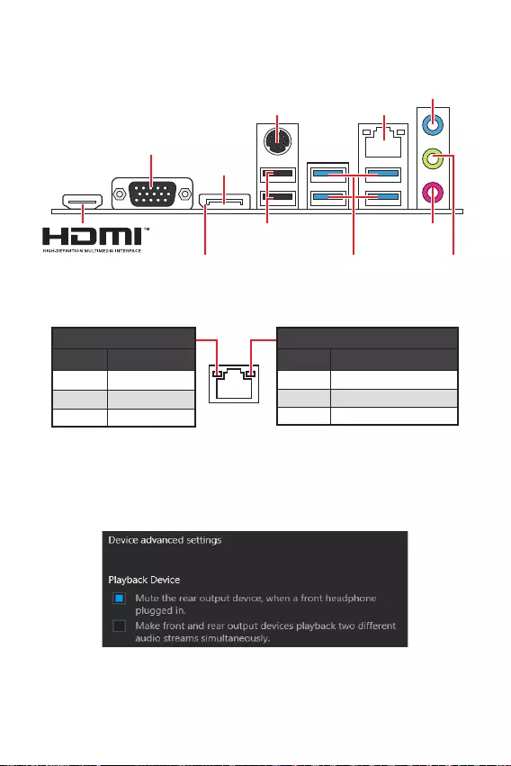
Off No link
Yellow Linked
Blinking Data activity
Off 10 Mbps connection
Green 100/ 1000 Mbps connection
Orange 2.5 Gbps connection
PS/2 Mouse/
Keyboard 2.5 Gbps LAN
USB 2.0 Type-A
DisplayPort
USB 3.2 Gen 1
5Gbps Type-A
Mic-in
Line-in
Line-out
VGA
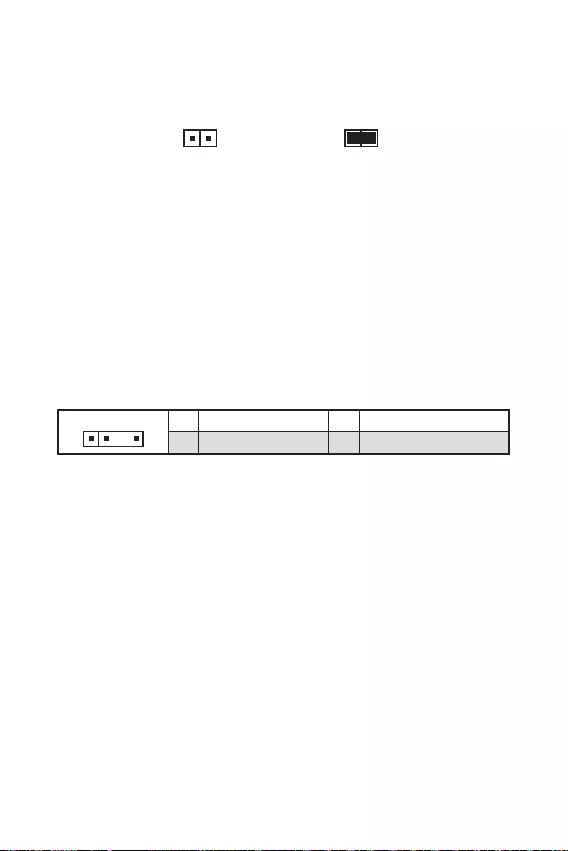
To configure 7.1-channel audio, you have to connect front audio I/O module to JAUD1
connector and follow the below steps.
Click on the Realtek HD Audio Manager > Advanced Settings to open the dialog
below.
Select Mute the rear output device, when a front headphone plugged in.
Plug your speakers to audio jacks on rear and front I/O panel. When you plug into
a device at an audio jack, a dialogue window will pop up asking you which device
is current connected.
(For B560M PRO only)
9
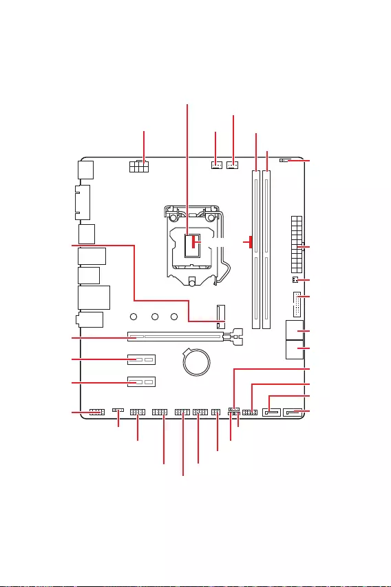
BAT1
* Distance from the center of the CPU to the nearest DIMM slot.
53.25mm*
SYS_FAN1
CPU_FAN1
CPU Socket
JRAINBOW1
PCI_E2
M2_1
PCI_E3
PCI_E1
DIMMA1
DIMMB1
JBAT1
JDASH1
SATA5
SATA6
JFP1
JCOM1
JAUD1
ATX_PWR1
CPU_PWR1
JUSB3
JSMB1
JUSB2
JTPM1
JUSB1
JFP2
JCI1
JRGB1

10
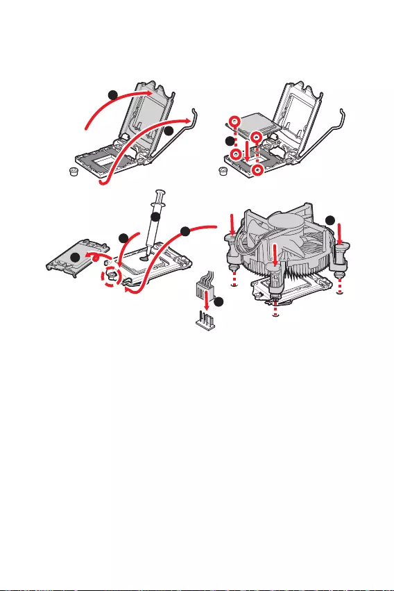
Please install the CPU into the CPU socket as shown below.
Always unplug the power cord from the power outlet before installing or removing
the CPU.
Please retain the CPU protective cap after installing the processor. MSI will deal
with Return Merchandise Authorization (RMA) requests if only the motherboard
comes with the protective cap on the CPU socket.
When installing a CPU, always remember to install a CPU heatsink. A CPU heatsink
is necessary to prevent overheating and maintain system stability.
your system.
Overheating can seriously damage the CPU and motherboard. Always make sure
the cooling fans work properly to protect the CPU from overheating. Be sure to apply
an even layer of thermal paste (or thermal tape) between the CPU and the heatsink to
enhance heat dissipation.
Whenever the CPU is not installed, always protect the CPU socket pins by covering
the socket with the plastic cap.
If you purchased a separate CPU and heatsink/ cooler, Please refer to the docu-
mentation in the heatsink/ cooler package for more details about installation.
1
4
78
9
3
2

11
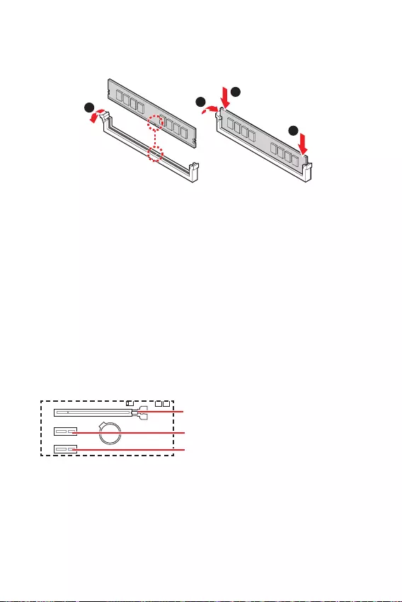
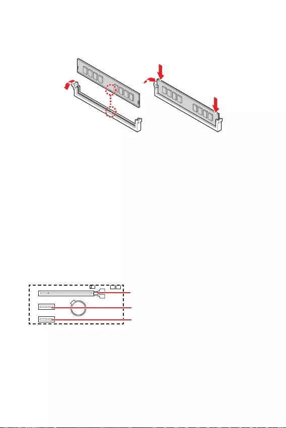
Please install the memory module into the DIMM slot as shown below.
Please install the memory module into the DIMM slot as shown below.
Always insert memory modules in the
To ensure system stability for Dual channel mode, memory modules must be of the
same type, number and density.
Some memory modules may operate at a lower frequency than the marked value
when overclocking due to the memory frequency operates dependent on its Serial
frequency if you want to operate the memory at the marked or at a higher frequency.
installation or overclocking.
The stability and compatibility of installed memory module depend on installed
CPU and devices when overclocking.
Please refer www.msi.com for more information on compatible memory.
unplug the power supply power cable from the power outlet. Read the expansion
card’s documentation to check for any necessary additional hardware or software
changes.
If you install a large and heavy graphics card, you need to use a tool such as
to support its weight to prevent deformation
of the slot.
BAT1
: PCIe 4.0 x16 slot (From CPU)
: PCIe 3.0 x1 slot (From B560 chipset)
: PCIe 3.0 x1 slot (From B560 chipset)
1
2
3
2
12
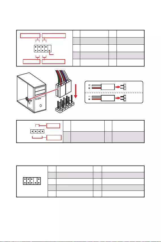
These connectors connect to the switches and LEDs on the front panel.
1
2 10
9
+
+
+— ——
—
+
Power LED
HDD LED Reset Switch
Reserved
Power Switch 1 HDD LED + 2 Power LED +
3 HDD LED — 4 Power LED —
5 Reset Switch 6 Power Switch
7 Reset Switch 8 Power Switch
9 Reserved 10 No Pin
JFP2 1
+
+—
—
Speaker
Buzzer 1 Speaker — 2 Buzzer +
3 Buzzer — 4 Speaker +
HDD LED
RESET SW
HDD LED HDD LED —
HDD LED +
POWER LED —
POWER LED +
POWER LED
JFP1
This connector allow you to connect audio jacks on the front panel.
1
2 10
9
1 MIC L 2 Ground
3 MIC R 4 NC
5 Head Phone R 6 MIC Detection
7 SENSE_SEND 8 No Pin
9 Head Phone L 10 Head Phone Detection
13
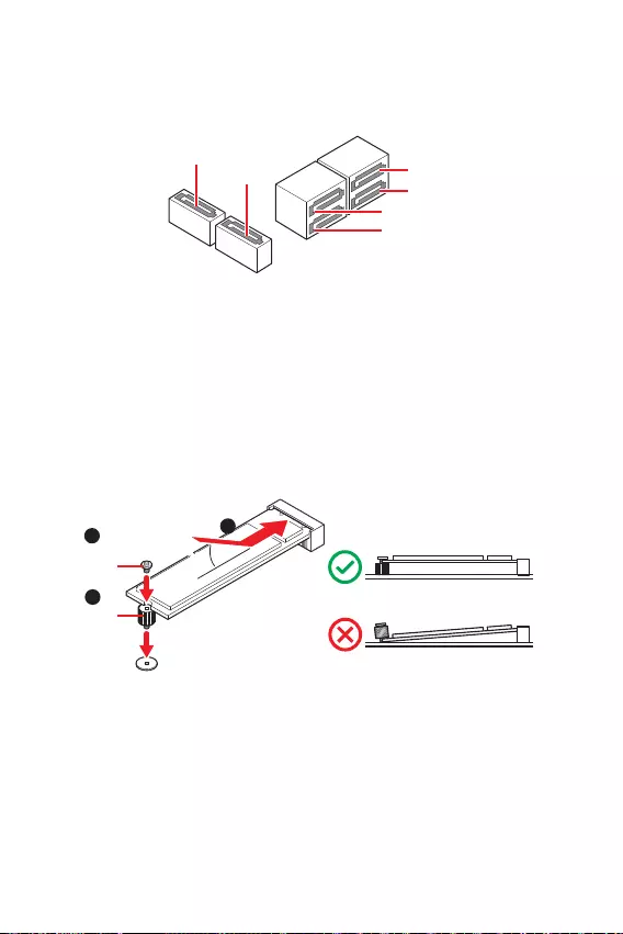
These connectors are SATA 6Gb/s interface ports. Each connector can connect to one
SATA device.
SATA3
SATA1
SATA4
SATA5
SATA6
SATA2
Please do not fold the SATA cable at a 90-degree angle. Data loss may result
during transmission otherwise.
SATA cables have identical plugs on either sides of the cable. However, it is
saving purposes.
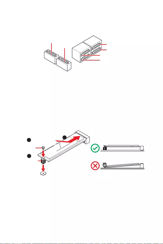
Please install the M.2 solid-state drive (SSD) into the M.2 slot as shown below.
1
3
Standoff
Supplied
M.2 screw 30º30º
2

14
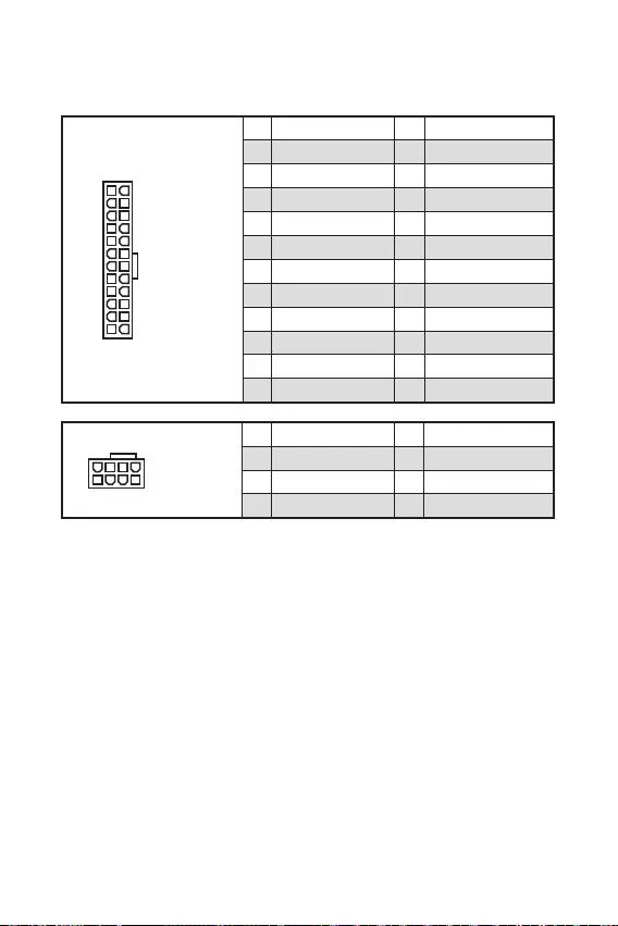
These connectors allow you to connect an ATX power supply.
Make sure that all the power cables are securely connected to a proper ATX power
supply to ensure stable operation of the motherboard.
24
131
12
ATX_PWR1
1 +3.3V 13 +3.3V
2 +3.3V 14 -12V
3 Ground 15 Ground
4 +5V 16 PS-ON#
5 Ground 17 Ground
6 +5V 18 Ground
7 Ground 19 Ground
8 PWR OK 20 Res
9 5VSB 21 +5V
10 +12V 22 +5V
11 +12V 23 +5V
12 +3.3V 24 Ground
5
41
8
CPU_PWR1
1 Ground 5 +12V
2 Ground 6 +12V
3 Ground 7 +12V
4 Ground 8 +12V

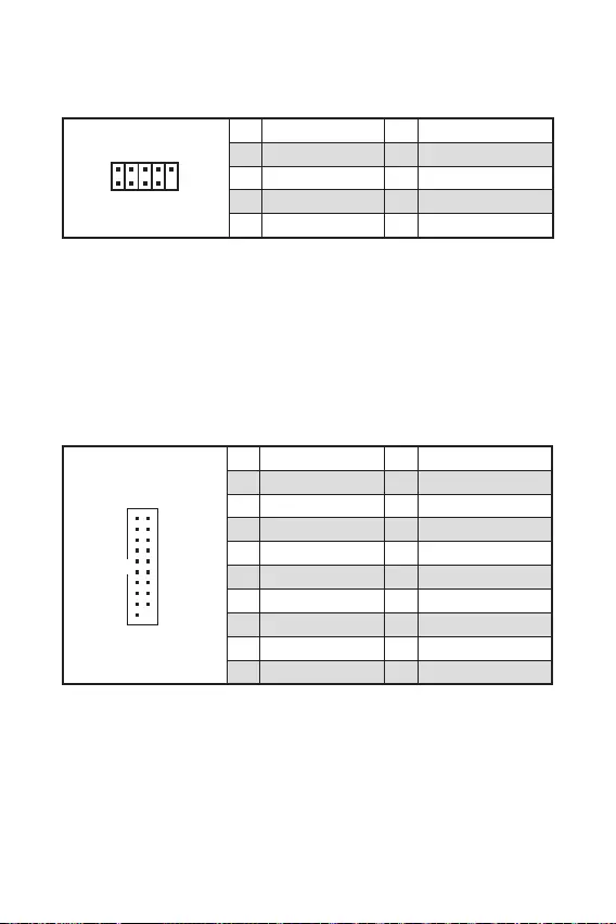
This connector allows you to connect USB 3.2 Gen 1 5Gbps ports on the front panel.
1
10 11
20
1 Power 11 USB2.0+
2 USB3_RX_DN 12 USB2.0-
3 USB3_RX_DP 13 Ground
4 Ground 14 USB3_TX_C_DP
5 USB3_TX_C_DN 15 USB3_TX_C_DN
6 USB3_TX_C_DP 16 Ground
7 Ground 17 USB3_RX_DP
8 USB2.0- 18 USB3_RX_DN
9 USB2.0+ 19 Power
10 Ground 20 No Pin
Note that the Power and Ground pins must be connected correctly to avoid possible
damage.
These connectors allow you to connect USB 2.0 ports on the front panel.
Note that the VCC and Ground pins must be connected correctly to avoid possible
damage.
In order to recharge your iPad,iPhone and iPod through USB ports, please install
MSI® Center utility.
1
2 10
9
1 VCC 2 VCC
3 USB0- 4 USB1-
5 USB0+ 6 USB1+
7 Ground 8 Ground
9 No Pin 10 NC
1
212
11
1 SPI Power 2 SPI Chip Select
3
Master In Slave Out
(SPI Data)
4
Master Out Slave In
(SPI Data)
5 Reserved 6 SPI Clock
7 Ground 8 SPI Reset
9 Reserved 10 No Pin
11 Reserved 12 Interrupt Request
This connector is for TPM (Trusted Platform Module). Please refer to the TPM
security platform manual for more details and usages.
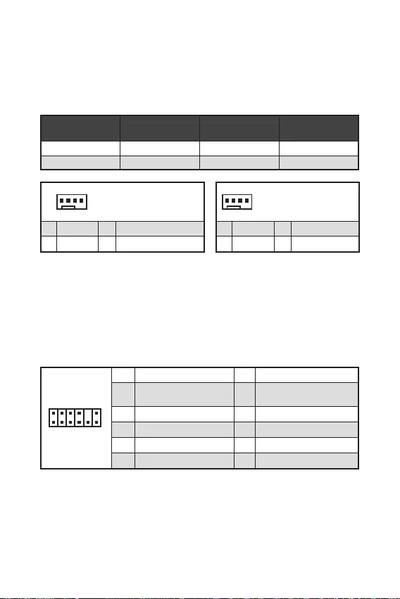
Fan connectors can be classified as PWM (Pulse Width Modulation) Mode or DC
Mode. PWM Mode fan connectors provide constant 12V output and adjust fan speed
with speed control signal. DC Mode fan connectors control fan speed by changing
voltage.
You can adjust fan speed in
1
1 Ground 2 +12V
3 Sense 4 Speed Control Signal
CPU_FAN1 PWM mode 2A 24W
SYS_FAN1 DC mode 1A 12W
1
1 Ground 2 Voltage Control
3 Sense 4 NC
17
This connector allows you to connect the chassis intrusion switch cable.
Normal
(default) Trigger the chassis
intrusion event
Connect the connector to the chassis intrusion switch/ sensor on the
chassis.
Close the chassis cover.
Go to .
Set to .
Press F10 to save and exit and then press the key to select .
Once the chassis cover is opened again, a warning message will be displayed on
screen when the computer is turned on.
Go to .
Set to Reset.
Press to save and exit and then press the key to select .
This connector allows you to connect the optional serial port with bracket.
This connector is used to connect an optional Tuning Controller module.
1
2 10
9
1 DCD 2 SIN
3 SOUT 4 DTR
5 Ground 6 DSR
7 RTS 8 CTS
9 RI 10 No Pin
1
2 6
5
1 No pin 2 NC
3 MCU_SMB_SCL_M 4 MCU_SMB_SDA_M
5 VCC5 6 Ground

18
There is CMOS memory onboard that is external powered from a battery located on
the motherboard to save system configuration data. If you want to clear the system
configuration, set the jumpers to clear the CMOS memory.
Keep Data
(default) Clear CMOS/
Reset BIOS
Power off the computer and unplug the power cord.
Use a jumper cap to short for about 5-10 seconds.
Remove the jumper cap from .
Plug the power cord and power on the computer.
The JRAINBOW connector allows you to connect the WS2812B Individually
Addressable RGB LED strips 5V.
Do not connect the wrong type of LED strips. The JRGB connector and the JRAINBOW
connector provide different voltages, and connecting the 5V LED strip to the JRGB
connector will result in damage to the LED strip.
The JRAINBOW connector supports up to 75 LEDs WS2812B Individually Address-
able RGB LED strips (5V/Data/Ground) with the maximum power rating of 3A (5V). In
the case of 20% brightness, the connector supports up to 200 LEDs.
before installing or removing the RGB LED strip.
Please use MSI’s software to control the extended LED strip.
11 +5V 2 Data
3 No Pin 4 Ground
19
The JRGB connector allows you to connect the 5050 RGB LED strips 12V.
The JRGB connector supports up to 2 meters continuous 5050 RGB LED strips
(12V/G/R/B) with the maximum power rating of 3A (12V).
before installing or removing the RGB LED strip.
Please use MSI’s software to control the extended LED strip.
11 +12V 2 G
3 R 4 B
These LEDs indicate the status of the motherboard.
— indicates DRAM is not detected or fail.
— indicates GPU is not detected or fail.
— indicates booting device is not detected or fail.
— indicates CPU is not detected or fail.

20
Please download and update the latest utilities and drivers at www.msi.com
Power on the computer.
Insert the Windows® 10 installation disc/USB into your computer.
Press the button on the computer case.
Press F11 key during the computer POST (Power-On Self Test) to get into Boot
Menu.
Select the Windows® 10 installation disc/USB from the Boot Menu.
Press any key when screen shows
message.
Follow the instructions on the screen to install Windows® 10.
Start up your computer in Windows® 10.
Insert MSI® Drive disc into the optical drive.
Click the pop-up notification,
then select to open the installer. If you turn off the AutoPlay
feature from the Windows Control Panel, you can still manually execute the
from the root path of the MSI Drive disc.
The installer will find and list all necessary drivers in the tab.
Click the button in the lower-right corner of the window.
The drivers installation will then be in progress, after it has finished it will prompt
you to restart.
Click button to finish.
Restart your computer.
MSI Center is an application that helps you easily optimize game settings and
smoothly use content creation softwares. It also allows you to control and
synchronize LED light effects on PCs and other MSI products. With MSI Center, you
can customize ideal modes, monitor system performance, and adjust fan speed.
If you would like to know more information about MSI Center, please
refer to
http://download.msi.com/manual/mb/MSICENTER.pdf
or scan the QR code to access.
Functions may vary depending on the product you have.

21
MSI UEFI BIOS is compatible with UEFI (Unified Extensible Firmware Interface)
architecture. UEFI has many new functions and advantages that traditional BIOS
cannot achieve, and it will completely replace BIOS in the future. The MSI UEFI
BIOS uses UEFI as the default boot mode to take full advantage of the new chipset’s
capabilities.
The term BIOS in this user guide refers to UEFI BIOS unless otherwise noted.
Fast booting — UEFI can directly boot the operating system and save the BIOS self-
test process. And also eliminates the time to switch to CSM mode during POST.
Supports for hard drive partitions larger than 2 TB.
Supports more than 4 primary partitions with a GUID Partition Table (GPT).
Supports unlimited number of partitions.
Supports full capabilities of new devices — new devices may not provide backward
compatibility.
Supports secure startup — UEFI can check the validity of the operating system to
ensure that no malware tampers with the startup process.
— this motherboard supports only 64-bit
Windows 10 operating system.
— the system will detect your graphics card. When display a
warning message
We recommend that you to replace with a GOP/UEFI compatible graphics card or
using integrated graphics from CPU for having normal function.
Power on your computer.
Press key, when the
message appears on the screen during the boot process.
After entering the BIOS, you can check the at the top of the screen.

22
The default settings offer the optimal performance for system stability in normal
conditions. You should to avoid possible system
damage or failure booting unless you are familiar with BIOS.
BIOS items are continuously update for better system performance. Therefore, the
only. You could also refer to the information panel for BIOS item description.
The BIOS screens, options and settings will vary depending on your system.
Press key, when the
message appears on the screen during the boot process.
F1: General Help
F2: Add/ Remove a favorite item
F3: Enter Favorites menu
F4: Enter CPU Specifications menu
: Enter Memory-Z menu
: Load optimized defaults
F7: Switch between Advanced mode and EZ mode
F8: Load Overclocking Profile
F9: Save Overclocking Profile
F10: Save Change and Reset*
F12: Take a screenshot and save it to USB flash drive (FAT/ FAT32 format only).
: Enter Search page
* When you press F10, a confirmation window appears and it provides the
modification information. Select between Yes or No to confirm your choice.
If you’d like to know more instructions on setting up the BIOS,
please refer to
http://download.msi.com/manual/mb/Intel500BIOS.pdf
or scan the QR code to access.

23
You might need to restore the default BIOS setting to solve certain problems. There
are several ways to reset BIOS:
Go to BIOS and press to load optimized defaults.
Short the Clear CMOS jumper on the motherboard.
Press the Clear CMOS button on the rear I/O panel.
Be sure the computer is off before clearing CMOS data. Please refer to the Clear
CMOS jumper/ button section for resetting BIOS.
Before updating:
Please download the latest BIOS file that matches your motherboard model from MSI
website. And then save the BIOS file into the USB flash drive.
Updating BIOS:
Insert the USB flash drive that contains the update file into the USB port.
Please refer the following methods to enter flash mode.
Reboot and press key during POST and click on to reboot the
system.
Reboot and press key during POST to enter BIOS. Click the
button and click on to reboot the system.
Select a BIOS file to perform the BIOS update process.
When prompted click on to start recovering BIOS.
After the flashing process is 100% completed, the system will reboot
automatically.

24
Before updating:
Make sure the LAN driver is already installed and the internet connection is set
properly.
Please close all other application software before updating the BIOS.
To update BIOS:
Install and launch MSI Center and go to page.
Select and click on button.
Select the BIOS file and click on button.
The installation reminder will appear, then click the button on it.
The system will automatically restart to update BIOS.
After the flashing process is 100% completed, the system will restart
automatically.

1
……………………………………………………………………………………………………….2
3
8
9
…………………………………………………………………………………………………….10
…………………………………………………………………………………………………..11
……………………………………………………………………………..11
…………………………………………………………………………12
…………………………………………………………………………….12
………………………………………………………………………..13
…………………………………………………………………………………13
ATX_PWR1, CPU_PWR1:
……………………………………………………………….14
……………………………………………………………………………..15
………………………………………………………………15
………………………………………………………………….16
……………………………………………………………………………….16
…………………………………………………………………………………..17
…………………………………………………………………………….17
……………………………………………………………………….17
………………………………………………………….18
……………………………………………….18
……………………………………………………………………………….19
…………………………………………………………………………………………….19
20
21
……………………………………………………………………………………..22
……………………………………………………………………………………………………22
……………………………………………………………………………………………………23
………………………………………………………………………………..23
MSI®

2

3
B560
1DPC 1R 5200 MHz
1DPC 2R 4700+ MHz
1920×1200 @60Hz*/**
/**

4
(B560 )
PCIe 4.0×4 (CPU)
PCIe 3.0×4 (B560 )
2242/ 2260/ 2280
® B560
USB 2.0 6 (, USB 2.0
)
USB 3.2 Gen 1 5Gbps 6 (,
Realtek® ALC897
7.1-
Realtek® 8125B 2.5Gbps LAN


9.3 in. x 8.0 in. (23.6 cm x 20.2 cm)
UEFI AMI BIOS
ACPI 6.2, SMBIOS 3.0
True Color

7
2.5G LAN
LED
USB3.2 Gen1 5G
PCI-E
8
2.5 Gbps LAN
USB 2.0
USB 3.2 Gen 1
5Gbps
VGA
Realtek HD Audio Manager(Realtek HD > Advanced Settings

9
BAT1
53.25mm*
SYS_FAN1
CPU_FAN1
JRAINBOW1
PCI_E2
M2_1
PCI_E3
PCI_E1
DIMMA1
DIMMB1
JBAT1
JDASH1
SATA5
SATA6
JFP1
JCOM1
JAUD1
ATX_PWR1
CPU_PWR1
JUSB3
JUSB2
JTPM1
JUSB1
JFP2
JCI1
JRGB1
10
1
4
78
9
3
2

11
BAT1
1
2
3
2

12
1
2 10
9
+
+
+— ——
—
+
HDD LED
Reserved
1 HDD LED + 2 Power LED +
3 HDD LED — 4 Power LED —
5 Reset Switch 6 Power Switch
7 Reset Switch 8 Power Switch
9 Reserved 10 No Pin
JFP2 1
+
+—
—
Speaker
Buzzer 1 Speaker — 2 Buzzer +
3 Buzzer — 4 Speaker +
HDD LED
RESET SW
HDD LED HDD LED —
HDD LED +
POWER LED —
POWER LED +
POWER LED
JFP1
1
2 10
9
1 MIC L 2 Ground
3 MIC R 4 NC
5 Head Phone R 6 MIC Detection
7 SENSE_SEND 8 No Pin
9 Head Phone L 10 Head Phone Detection

13
SATA3
SATA1
SATA4
SATA5
SATA6
SATA2
1
3
30º30º
2

14
24
131
12
ATX_PWR1
1 +3.3V 13 +3.3V
2 +3.3V 14 -12V
3 Ground 15 Ground
4 +5V 16 PS-ON#
5 Ground 17 Ground
6 +5V 18 Ground
7 Ground 19 Ground
8 PWR OK 20 Res
9 5VSB 21 +5V
10 +12V 22 +5V
11 +12V 23 +5V
12 +3.3V 24 Ground
5
41
8
CPU_PWR1
1 Ground 5 +12V
2 Ground 6 +12V
3 Ground 7 +12V
4 Ground 8 +12V

1
10 11
20
1 Power 11 USB2.0+
2 USB3_RX_DN 12 USB2.0-
3 USB3_RX_DP 13 Ground
4 Ground 14 USB3_TX_C_DP
5 USB3_TX_C_DN 15 USB3_TX_C_DN
6 USB3_TX_C_DP 16 Ground
7 Ground 17 USB3_RX_DP
8 USB2.0- 18 USB3_RX_DN
9 USB2.0+ 19 Power
10 Ground 20 No Pin
®
1
2 10
9
1 VCC 2 VCC
3 USB0- 4 USB1-
5 USB0+ 6 USB1+
7 Ground 8 Ground
9 No Pin 10 NC
1
212
11
1 SPI Power 2 SPI Chip Select
3
Master In Slave Out
(SPI Data)
4
Master Out Slave In
(SPI Data)
5 Reserved 6 SPI Clock
7 Ground 8 SPI Reset
9 Reserved 10 No Pin
11 Reserved 12 Interrupt Request
1
1 Ground 2 +12V
3 Sense 4 Speed Control Signal
CPU_FAN1 2A 24W
SYS_FAN1 1A 12W
1
1 Ground 2 Voltage Control
3 Sense 4 NC

17
F10
1
2 10
9
1 DCD 2 SIN
3 SOUT 4 DTR
5 Ground 6 DSR
7 RTS 8 CTS
9 RI 10 No Pin
1
2 6
5
1 No pin 2 NC
3 MCU_SMB_SCL_M 4 MCU_SMB_SDA_M
5 VCC5 6 Ground
18
11 +5V 2 Data
3 No Pin 4 Ground

19
11 +12V 2 G
3 R 4 B

20
http://download.msi.com/manual/mb/MSICENTER.pdf

21

22
F1
F2
F3
F4
F7
F8
F9
F10
F12
http://download.msi.com/manual/mb/Intel500BIOSkr.pdf

23

24

1
2
3
8
Tableau explicatif de l’état de la LED du port LAN …………………………………………….8
9
Socket Processeur ………………………………………………………………………………………10
Slots DIMM …………………………………………………………………………………………………11
PCI_E1~3 : Slots d’extension PCIe …………………………………………………………………11
JFP1, JFP2 : Connecteurs de panneau avant ………………………………………………….12
JAUD1 : Connecteur audio avant……………………………………………………………………12
SATA1~6 : Connecteurs SATA 6 Gb/s …………………………………………………………….13
M2_1 : Slot M.2 (Touche M) …………………………………………………………………………..13
ATX_PWR1, CPU_PWR1 : Connecteurs d’alimentation …………………………………….14
JUSB1~2 : Connecteurs USB 2.0 …………………………………………………………………..15
JUSB3 : Connecteur USB 3.2 Gen 1 5 Gb/s …………………………………………………….15
CPU_FAN1, SYS_FAN1 : Connecteurs de ventilateur ………………………………………16
JTPM1 : Connecteur de module TPM ……………………………………………………………..16
JCI1 : Connecteur intrusion châssis ………………………………………………………………17
JCOM1 : Connecteur de port série …………………………………………………………………17
JDASH1 : Connecteur du contrôleur de réglages…………………………………………….17
JBAT1 : Cavalier Clear CMOS (Réinitialiser le BIOS) ………………………………………..18
JRAINBOW1 : Connecteur LED RGB adressable ……………………………………………..18
JRGB1 : Connecteur LED RGB ………………………………………………………………………19
EZ Debug LED …………………………………………………………………………………………….19
20
22
Configuration du BIOS ………………………………………………………………………………….23
Entrer dans l’interface Setup du BIOS ……………………………………………………………23
Guide d’utilisation du BIOS ……………………………………………………………………………23
Réinitialiser le BIOS …………………………………………………………………………………….24
Mettre le BIOS à jour ……………………………………………………………………………………24
Merci d’avoir acheté la carte mère MSI®
. Ce guide d’utilisation
fournit des informations sur le schéma, la vue d’ensemble
des logiciels.

2
Les composants dans l’emballage peuvent être endommagés par des décharges
électrostatiques (ESD). Pour vous assurer de correctement monter votre ordinateur,
veuillez vous référer aux instructions ci-dessous.
Assurez-vous de bien connecter tous les composants. En cas de mauvaise
connexion, il se peut que l’ordinateur ne reconnaisse pas le composant et que le
démarrage échoue.
Veuillez tenir la carte mère par les bords pour éviter de toucher les composants
sensibles.
Il est recommandé de porter un bracelet antistatique lors de la manipulation de la
carte mère pour prévenir tout dommage. Si vous n’avez pas de bracelet antistatique,
touchez un objet métallique relié à la terre avant de manipuler la carte mère afin de
vous décharger de votre charge statique. Touchez régulièrement l’objet métallique
pendant toute la manipulation.
Tant que la carte mère n’est pas installée, conservez-la dans un récipient protégé
contre les ondes électrostatiques ou sur une couche antistatique.
Avant de démarrer l’ordinateur, vérifiez si toutes les vis et les composants
métalliques sont bien fixés sur la carte mère ou ailleurs dans le boîtier de
l’ordinateur.
Ne démarrez pas l’ordinateur avant d’avoir terminé l’installation. Ceci peut
endommager les composants ou vous blesser.
Si vous avez besoin d’aide pendant l’installation, veuillez consulter un technicien
informatique certifié.
Avant d’installer les composants d’ordinateur, veuillez toujours mettre hors
tension et débrancher le cordon d’alimentation.
Gardez ce manuel pour références futures.
Protégez ce manuel contre l’humidité.
Avant de brancher le bloc d’alimentation sur la sortie électrique, veuillez
vous assurer que la tension de la sortie électrique est bien égale à celle du bloc
d’alimentation.
Placez le cordon d’alimentation de façon à éviter que l’on marche dessus. Ne posez
rien sur le cordon d’alimentation.
Veuillez prêter attention à toutes les alertes et remarques indiquées sur la carte
mère.
Dans un cas comme ci-dessous, faites appel au service autorisé pour vérifier votre
carte mère :
Un liquide a pénétré dans l’ordinateur.
La carte mère a été exposée à de l’humidité.
La carte mère ne fonctionne pas comme indiqué dans les instructions.
La carte mère est tombée par terre et a été endommagée.
La carte mère est cassée.
Ne pas mettre la carte mère dans un environnement dont la température est
supérieure à 60 °C (140 °F) sous peine de l’endommager.

3
Support des processeurs Intel® Core™ de 10ème génération,
Intel® Core™ de 11ème génération, Pentium® Gold et Celeron® *
Socket LGA1200
* Veuillez vous au site www.intel.com pour plus d’informations
de compatibilité.
Chipset Intel® B560
2 x slots pour mémoire DDR4, support jusqu’à 64Go*
Support 1R 2133/ 2666/ 2933 MHz pour processeur Intel® de
10ème génération (par JEDEC et POR)
Support 1R 2133/ 2666/ 2933/ 3200 MHz pour processeur Intel®
de 11ème génération (par JEDEC et POR)
Fréquence d’overclocking maximale :
La fréquence maximale en mode 1DPC 1R monte jusqu’à
5200 MHz
La fréquence maximale en mode 1DPC 2R monte jusqu’à
4700+ MHz
Support mode double canal
Support non-ECC, mémoire un-buffered
Support Intel® Extreme Memory Profile (XMP)
* Veuillez vous référer au site www.msi.com pour plus
d’informations sur la mémoire compatible.
1 x slot PCIe x16 (depuis CPU)
Support jusqu’à PCIe 4.0 pour processeur Intel® de 11ème
génération
Support jusqu’à PCIe 3.0 pour processeur Intel® de 10ème
génération
2 x slots PCIe 3.0 x1 (depuis Chipset B560)
Suite du tableau sur la page suivante

4
Suite du tableau sur la page précédente
1 x port VGA, supportant une résolution maximum de
2048×1536 @50 Hz, 2048×1280 @60 Hz, 1920×1200 @60 Hz*/**
1 x port DisplayPort 1.4, supportant une résolution maximum
de 4K 60Hz*/** (Uniquement pour B560M PRO)
1 x port HDMI 2.0b avec HDR, supportant une résolution
maximum de 4K 60 Hz*/**
* Disponible uniquement pour le processeur avec puce
graphique intégrée.
** Les caractéristiques des cartes graphiques peuvent varier en
fonction du processeur installé.
6 x ports SATA 6 Gb/s (depuis Chipset B560)
1 x slot M.2 (Touche M)*
Support jusqu’à PCIe 4.0×4 (depuis CPU)
Disponible sur les processeurs Intel® de 11ème
génération
Support PCIe 3.0×4 (depuis Chipset B560)
Support des périphériques de stockage 2242 / 2260 / 2280
Support technologie Intel® Smart Response pour les
processeurs Intel Core™
Chipset Intel® B560
6 x ports USB 2.0 (2 ports Type-A sur le panneau arrière,
4 ports disponibles par l’intermédiaire des connecteurs USB
2.0 internes)
6 x ports USB 3.2 Gen 1 5 Gb/s (4 ports Type-A sur le
panneau arrière, 2 ports disponibles par l’intermédiaire du
connecteur USB 3.2 Gen1 interne)
Realtek® ALC897 Codec
Audio haute définition 7.1
1 x contrôleur Realtek® 8125B 2,5 Gb/s LAN
Suite du tableau sur la page suivante

Suite du tableau sur la page précédente
1 x connecteur d’alimentation principal ATX à 24 broches
1 x connecteur d’alimentation ATX 12 V à 8 broches
6 x connecteurs SATA 6 Gb/s
1 x slot M.2 (Touche M)
1 x connecteur USB 3.2 Gen 1 5 Gb/s (support de 2 autres
ports USB 3.2 Gen 1 5 Gb/s)
2 x connecteurs USB 2.0 (support de 4 autres ports USB 2.0)
1 x connecteur de ventilateur CPU à 4 broches
1 x connecteur de ventilateur système à 4 broches
1 x connecteur audio avant
2 x connecteurs de panneau système
1 x connecteur intrusion châssis
1 x cavalier Clear CMOS
1 x connecteur de module TPM
1 x connecteur de port série
1 x connecteur du contrôleur de réglages
1 x connecteur LED RGB à 4 broches (Pour B560M PRO et
B560M BOMBER)
1 x connecteur LED RAINBOW à 3 broches (Pour B560M PRO
et B560M BOMBER)
4 x EZ Debug LED
1 x port HDMI
1 x port VGA
1 x DisplayPort (Uniquement pour B560M PRO)
1 x port combo souris/clavier PS/2
2 x ports USB 2.0 Type-A
4 x ports USB 3.2 Gen1 5 Gb/s Type-A
1 x port LAN (RJ45)
3 x jacks audio
Contrôleur NUVOTON NCT6687-R
Suite du tableau sur la page suivante

Suite du tableau sur la page précédente
Détection de la température du CPU, du système et du Chipset
Détection de la vitesse du ventilateur du CPU, du système et
du ventilateur de pompe
Contrôle de la vitesse du ventilateur du CPU, du système et du
ventilateur de pompe
Format Micro-ATX
23,6 cm x 20,2 cm (9,3” x 8,0”)
1 x flash 256 Mb
UEFI AMI BIOS
ACPI 6.2, SMBIOS 3.0
Multilingue
Pilotes
MSI Center
Intel® Extreme Tuning Utility
CPU-Z MSI GAMING
Google Chrome™, Google Toolbar, Google Drive
Norton™ Internet Security Solution
Mystic Light (Pour B560M PRO et B560M BOMBER)
LAN Manager
User Scenario
Hardware Monitor
Frozr AI Cooking
True Color
Live Update
Speed Up
Super Charger
Suite du tableau sur la page suivante

7
Suite du tableau sur la page précédente
Audio
Audio Boost
Network
2,5 G LAN
LAN Manager
Cooling
1x M.2 Shield Frozr
Smart Fan Control
LED
Mystic Light Extension (RAINBOW/RGB) (Pour B560M PRO
et B560M BOMBER)
Mystic Light SYNC
EZ DEBUG LED
Performance
DDR4 Boost
Core Boost
USB3.2 Gen1 5 G
USB de Type A
Front USB Type-A
Protection
PCI-E Steel Armor
Expérience
Click BIOS 5
8
Etat
Eteint Pas de connexion
Jaune Connexion correcte
Clignote Activité en cours
Etat
Eteint 10 Mb/s
Vert 100 / 1000 Mb/s
Orange 2,5 Gb/s
Souris/clavier PS/2 2,5 Gb/s LAN
USB 2.0 Type-A
DisplayPort
USB 3.2 Gen 1
5 Gb/s Type-A
Entrée microphone
Entrée ligne
Sortie ligne
VGA
Pour régler le système audio 7.1, connectez le module audio entrée/sortie du
panneau avant au connecteur JAUD1 et suivez les étapes ci-dessous.
Cliquez sur Realtek HD Audio Manager > Advanced Settings pour ouvrir le
dialogue suivant.
Choisissez Mute the rear output device, when a front headphone plugged in.
(Passer le périphérique arrière en silencieux quand un casque est branché à
l’avant.)
Branchez vos haut-parleurs aux prises audio sur les panneaux entrée/sortie
arrière et avant. Lorsqu’un périphérique est branché sur une prise audio,
une fenêtre de dialogue apparaît et vous demande de choisir le périphérique
connecté que vous souhaitez utiliser.
(Uniquement pour B560M PRO)

9
BAT1
* Distance entre le centre du CPU et le slot DIMM le plus proche.
53.25mm*
SYS_FAN1
CPU_FAN1
Socket processeur
JRAINBOW1
PCI_E2
M2_1
PCI_E3
PCI_E1
DIMMA1
DIMMB1
JBAT1
JDASH1
SATA5
SATA6
JFP1
JCOM1
JAUD1
ATX_PWR1
CPU_PWR1
JUSB3
JUSB2
JTPM1
JUSB1
JFP2
JCI1
JRGB1

10
Installer le processeur dans le socket comme indiqué ci-dessous.
Avant d’installer ou de retirer le processeur du socket, veillez à toujours débranch-
er le câble d’alimentation de la prise électrique.
Veuillez garder le capot de protection du processeur après l’installation du
processeur. Selon les exigences de RMA (Return Merchandise Authorization), MSI
n’acceptera pas les cartes mère dont le capot de protection aura été retiré.
Lors de l’installation d’un processeur, n’oubliez pas d’installer un ventilateur pour
processeur. Un ventilateur de processeur est nécessaire pour protéger le proces—
Assurez-vous de l’étanchéité entre le ventilateur et le processeur avant de démar-
rer votre système.
Assurez-vous toujours que le système de refroidissement fonctionne correctement
de pâte thermique (ou adhésif thermique) entre le processeur et le système de
Quand le processeur n’est pas installé, protégez toujours les broches de l’em-
placement du processeur avec le couvercle dédié.
Si vous avez achetez un processeur indépendamment du ventilateur, veuillez vous
référer à la documentation dans le paquet du ventilateur pour plus d’informations
concernant l’installation.
1
4
78
9
3
2
11
Insérer le module de mémoire dans le slot DIMM comme indiqué ci-dessous.
Veillez à toujours insérer un module de mémoire dans le slot en premier.
Pour garantir la stabilité du système au mode de double canal, assurez-vous
d’installer les modules de mémoire du même type, du même nombre et de la même
densité.
Certaines mémoires peuvent fonctionner à une fréquence réduite par rapport à
la valeur indiquée lors de l’overclocking car la fréquence d’opération de mémoire
dépend du Serial Presence Detect (SPD). Rendez-vous sur le BIOS et choisissez la
fonction DRAM Frequency pour régler la fréquence de mémoire si vous voulez faire
fonctionner la mémoire à la fréquence indiquée ou à une fréquence plus élevée.
Il est recommandé d’utiliser un système de refroidissement qui sera capable de
overclocking.
La stabilité et la compatibilité du module de mémoire lors de l’overclocking dépen-
dent du processeur et des périphériques installés.
Veuillez vous référer au site www.msi.com pour plus d’informations sur la
mémoire compatible.
Veillez à toujours mettre l’ordinateur hors tension et à débrancher le cordon d’al-
imentation avant d’installer les cartes d’extension. Référez-vous à la documentation
Si vous installez une carte graphique lourde, il vous faut utiliser un outil comme
la pour supporter son poids et pour éviter la
déformation du slot.
BAT1
: PCIe 4.0 x16 (CPU)
: PCIe 3.0 x1 (Chipset B560)
: PCIe 3.0 x1 (Chipset B560)
1
2
3
2

12
Ces connecteurs se lient aux interrupteurs et indicateurs LED du panneau avant.
1
2 10
9
+
+
+— ——
—
+
Power LED
HDD LED Reset Switch
Reserved
Power Switch 1 HDD LED + 2 Power LED +
3 HDD LED — 4 Power LED —
5 Reset Switch 6 Power Switch
7 Reset Switch 8 Power Switch
9 Reserved 10 No Pin
JFP2 1
+
+—
—
Speaker
Buzzer 1 Speaker — 2 Buzzer +
3 Buzzer — 4 Speaker +
HDD LED
RESET SW
HDD LED HDD LED —
HDD LED +
POWER LED —
POWER LED +
POWER LED
JFP1
Ce connecteur se lie aux jacks audio du panneau avant.
1
2 10
9
1 MIC L 2 Ground
3 MIC R 4 NC
5 Head Phone R 6 MIC Detection
7 SENSE_SEND 8 No Pin
9 Head Phone L 10 Head Phone Detection

13
Ces connecteurs utilisent une interface SATA 6 Gb/s. Chaque connecteur peut être
relié à un appareil SATA.
SATA3
SATA1
SATA4
SATA5
SATA6
SATA2
Veuillez ne pas plier les câbles SATA à 90° car cela pourrait entraîner une perte de
données pendant la transmission.
Les câbles SATA disposent de prises identiques sur chaque côté. Néanmoins, il est
recommandé de connecter la prise plate sur la carte mère pour un gain d’espace.
Installer un SSD M.2 dans le slot M.2 comme indiqué ci-dessous.
1
3
Entretoise
Vis M.2 30º30º
2
14
Ces connecteurs vous permettent de relier une alimentation ATX.
Veuillez vous assurer que tous les câbles d’alimentation sont branchés aux
connecteurs adéquats afin garantir une opération stable de la carte mère.
24
131
12
ATX_PWR1
1 +3.3V 13 +3.3V
2 +3.3V 14 -12V
3 Ground 15 Ground
4 +5V 16 PS-ON#
5 Ground 17 Ground
6 +5V 18 Ground
7 Ground 19 Ground
8 PWR OK 20 Res
9 5VSB 21 +5V
10 +12V 22 +5V
11 +12V 23 +5V
12 +3.3V 24 Ground
5
41
8
CPU_PWR1
1 Ground 5 +12V
2 Ground 6 +12V
3 Ground 7 +12V
4 Ground 8 +12V
Ce connecteur vous permet de relier un port USB 3.2 Gen 1 5 Gb/s sur le panneau
avant.
1
10 11
20
1 Power 11 USB2.0+
2 USB3_RX_DN 12 USB2.0-
3 USB3_RX_DP 13 Ground
4 Ground 14 USB3_TX_C_DP
5 USB3_TX_C_DN 15 USB3_TX_C_DN
6 USB3_TX_C_DP 16 Ground
7 Ground 17 USB3_RX_DP
8 USB2.0- 18 USB3_RX_DN
9 USB2.0+ 19 Power
10 Ground 20 No Pin
Notez que les câbles d’alimentation et de terre doivent être branchés correctement
afin d’éviter d’endommager la carte.
Ces connecteurs vous permettent de relier des ports USB 2.0 sur le panneau avant.
d’éviter tout dommage sur la carte mère.
Pour recharger votre iPad, iPhone et iPod par l’intermédiaire d’un port USB,
veuillez installer l’utilitaire MSI® Center.
1
2 10
9
1 VCC 2 VCC
3 USB0- 4 USB1-
5 USB0+ 6 USB1+
7 Ground 8 Ground
9 No Pin 10 NC
1
212
11
1 SPI Power 2 SPI Chip Select
3
Master In Slave Out
(SPI Data)
4
Master Out Slave In
(SPI Data)
5 Reserved 6 SPI Clock
7 Ground 8 SPI Reset
9 Reserved 10 No Pin
11 Reserved 12 Interrupt Request
Ce connecteur est relié à un module TPM (Trusted Platform Module). Veuillez vous
référer au manuel du module TPM pour plus d’informations.
Les connecteurs de ventilateur peuvent être utilisés en mode PWM (Pulse Width
Modulation) et en mode DC. En mode PWM, les connecteurs fournissent une sortie
de 12 V constante et ajustent la vitesse du ventilateur avec un signal de contrôle
de vitesse. En mode DC, les connecteurs contrôlent la vitesse du ventilateur en
modifiant la tension.
Vous pouvez ajuster la vitesse du ventilateur dans le .
1
1 Ground 2 +12V
3 Sense 4 Speed Control Signal
CPU_FAN1 mode PWM 2 A 24 W
SYS_FAN1 mode DC 1 A 12 W
1
1 Ground 2 Voltage Control
3 Sense 4 NC
17
Ce connecteur est relié à un câble d’interrupteur intrusion châssis.
Normal
(défaut) Commencer l’activité
instrusion châssis
Reliez le connecteur à l’interrupteur ou au capteur d’intrusion châssis situé
sur le boîtier du PC.
Fermez le couvercle du boîtier.
Allez dans le
.
Réglez sur .
Appuyez sur F10 pour sauvegarder et quitter. Ensuite appuyez sur la touche
pour choisir .
Désormais, si le boîtier du PC est ouvert quand l’ordinateur est allumé, vous
recevrez un message d’alerte à l’écran.
Allez dans le
.
Mettez en .
Appuyez sur F10 pour sauvegarder et quitter. Ensuite appuyez sur la touche
pour choisir .
Ce connecteur vous permet de relier un port série en option.
Ce connecteur est utilisé pour connecter un contrôleur de réglage (selon modèle).
1
2 10
9
1 DCD 2 SIN
3 SOUT 4 DTR
5 Ground 6 DSR
7 RTS 8 CTS
9 RI 10 No Pin
1
2 6
5
1 No pin 2 NC
3 MCU_SMB_SCL_M 4 MCU_SMB_SDA_M
5 VCC5 6 Ground
18
Une mémoire CMOS est intégrée et est alimentée en externe par une batterie située
sur la carte mère afin de conserver les données de configuration système. Si vous
souhaitez nettoyer la configuration système, placez le cavalier sur Effacer CMOS de
manière à nettoyer la mémoire CMOS.
Conserver les
données (défaut) Effacer le CMOS/
Réinitialiser le BIOS
Eteignez l’ordinateur et débranchez le câble d’alimentation de la prise électrique.
Utilisez un couvercle de cavalier pour fermer pendant 5 à 10 secondes.
Enlevez le couvercle de cavalier du .
Branchez de nouveau le câble d’alimentation à votre ordinateur et allumez-le.
Le connecteur JRAINBOW vous permet de connecter un ruban à LED RGB WS2812B
adressable individuellement 5 V.
Faites attention à bien connecter le bon type de ruban LED. Le connecteur JRGB et
le connecteur JRAINBOW fournissent des tensions différentes. La connexion d’un
ruban LED 5 V au connecteur JRGB peut endommager le ruban.
Le connecteur JRAINBOW supporte jusqu’à des rubans 75 LEDs WS2812B adress-
ables individuellement (5 V/Data/Ground) avec une puissance nominale maximale de
3 A (5 V). Dans le cas d’une luminosité de 20 %, le connecteur supporte jusqu’à 200
LED.
Avant d’installer ou de retirer le ruban LED, veillez à toujours éteindre l’alimenta-
tion et à débrancher le câble d’alimentation de la prise électrique.
Veuillez utiliser un logiciel MSI dédié pour contrôler le ruban d’extension LED.
11 +5V 2 Data
3 No Pin 4 Ground

19
Le connecteur JRGB vous permet de connecter un ruban LED RGB de type 5050 12 V.
Le connecteur JRGB supporte des rubans LED RGB (12 V/G/R/B) de type 5050 d’une
longueur de 2 mètres maximum avec une puissance nominale maximale de 3 A (12 V).
Avant d’installer ou de retirer le ruban LED RGB, veillez à toujours éteindre l’ali-
mentation et à débrancher le câble d’alimentation de la prise électrique.
Veuillez utiliser un logiciel MSI dédié pour contrôler le ruban d’extension LED.
11 +12V 2 G
3 R 4 B
Ces LEDs indiquent l’état de débogage de la carte mère.
— indique que la mémoire DRAM n’est pas détectée ou que son initialisation
a échoué.
— indique que le GPU n’est pas détecté ou que son initialisation a échoué.
— indique que le périphérique de démarrage n’est pas détecté ou que son
initialisation a échoué.
— indique que le CPU n’est pas détecté ou que son initialisation a échoué.

20
Veuillez vous référer au site www.msi.com pour télécharger et mettre à jour les
derniers utilitaires et pilotes.
Allumez l’ordinateur.
Insérez le disque ou la clé USB d’installation de Windows® 10 dans votre
ordinateur.
Appuyez sur le bouton du boîtier de l’ordinateur.
Appuyez sur la touche F11 pendant le POST (Power-On Self Test) du système
pour entrer dans le menu de démarrage.
Choisissez le disque ou la clé USB d’installation de Windows® 10 dans le menu de
démarrage.
Appuyez sur n’importe quelle touche lorsqu’apparaît le message
.
Suivez les instructions à l’écran pour installer Windows® 10.
Allumez l’ordinateur sous Windows® 10.
Insérez MSI® Drive Disc dans le lecteur optique.
Cliquez sur la fenêtre popup
, puis choisissez
pour ouvrir l’outil d’installation. Si vous désactivez la fonction
AutoPlay dans le panneau de configuration Windows, vous pouvez quand même
exécuter manuellement à partir du chemin d’accès depuis la
racine du disque de pilotes MSI.
L’outil d’installation trouvera et listera tous les pilotes dont vous avez besoin
dans l’onglet .
Cliquez sur le bouton dans le coin inférieur droit de la fenêtre.
L’installation des pilotes commence. Une fois terminée, il vous sera demandé de
redémarrer.
Cliquez sur le bouton pour terminer.
Redémarrez votre ordinateur.

21
MSI Center est une application qui vous aide à optimiser facilement les paramètres
de jeu et à utiliser les logiciels de création de contenu de manière intuitive. Elle vous
permet également de contrôler et de synchroniser les effets de lumière LED sur les
PC et autres produits MSI. Avec MSI Center, vous pouvez personnaliser les modes
selon vos envies, surveiller les performances du système et régler la vitesse du
ventilateur.
Si vous souhaitez en savoir plus sur MSI Center, veuillez vous
référer au fichier
http://download.msi.com/manual/mb/MSICENTER.pdf
ou scannez le code QR pour y accéder.
Les fonctions peuvent varier en fonction du produit que vous possédez.

22
Le BIOS UEFI de MSI est compatible avec l’architecture UEFI (Unified Extensible
Firmware Interface). Le BIOS UEFI présente de nombreuses nouvelles
fonctionnalités et avantages qui ne sont pas proposés par le BIOS traditionnel. Le
BIOS UEFI est ainsi voué à totalement remplacer le BIOS traditionnel à l’avenir. Le
BIOS UEFI de MSI utilise UEFI comme mode de démarrage par défaut pour profiter
au maximum des capacités du nouveau chipset.
Dans ce guide d’utilisation, le terme BIOS se réfère au BIOS UEFI, sauf indication
contraire.
Démarrage rapide — L’UEFI peut démarrer directement le système d’exploitation
et enregistrer le processus d’autotest du BIOS. Il élimine également le temps à
attendre pour passer en mode CSM pendant le POST.
Prend en charge des partitions de disque dur supérieures à 2 To.
Prend en charge plus de 4 partitions principales avec une table de partition GUID
(GPT).
Prend en charge un nombre illimité de partitions.
Prend en charge toutes les capacités de nouveaux appareils — les nouveaux
appareils peuvent ne pas fournir de compatibilité descendante.
Prend en charge le démarrage sécurisé — L’UEFI peut vérifier la validité du
système d’exploitation pour s’assurer qu’aucun malware ne perturbe le processus
de démarrage.
— cette carte mère supporte uniquement
le système d’exploitation Windows 10 64 bits.
— le système détectera votre carte graphique. Un
message d’avertissement apparaît si
.
Nous vous recommandons de remplacer votre carte graphique par un modèle
compatible GOP/UEFI ou d’utiliser la puce graphique intégrée à votre processeur
pour profiter d’un fonctionnement normal.
Allumez votre ordinateur.
Pendant le démarrage, lorsqu’apparaît le message
sur l’écran, veuillez appuyer sur la touche .
Après être entré dans le BIOS, vous pouvez vérifier le en haut de
l’écran.

23
Les réglages par défaut fournissent une performance optimale pour la stabilité du
système en conditions normales. Veillez à
pour éviter d’endommager le système ou tout problème au démarrage, sauf si vous
êtes familier avec le BIOS.
—
n’est donc donnée qu’à titre de référence. Vous pouvez aussi vous référer à l’onglet
pour obtenir la description des fonctions du BIOS.
Les écrans, les options et les paramètres du BIOS peuvent varier selon votre
système.
Pendant le démarrage, lorsqu’apparaît le message
sur l’écran, veuillez appuyer sur la touche .
: Aide générale
F2 : Ajouter ou supprimer un élément favori
: Entrer dans le menu Favoris
: Entrer dans le menu de caractéristiques du processeur
: Entrer dans le menu Memory-Z
: Charger les réglages par défaut
: Alterner entre le mode avancé et le mode simplifié
: Charger le profil d’overclocking
: Sauvegarder le profil d’overclocking
: Sauvegarder les modifications et réglages*
: Prendre une capture d’écran et la conserver dans la clé USB (au format FAT/
FAT32 uniquement)
: Entrer dans la page de recherche
* Lorsque vous appuyez sur F10, une fenêtre de confirmation apparaît et fournit
l’information de modification. Choisissez entre Oui et Non pour confirmer.
Si vous souhaitez en savoir plus sur la configuration du BIOS,
veuillez vous référer au fichier
http://download.msi.com/manual/mb/Intel500BIOSfr.pdf
ou scannez le code QR pour y accéder.

24
Il se peut que vous ayez besoin de récupérer les réglages BIOS par défaut pour
résoudre des problèmes. Pour réinitialiser les réglages du BIOS, veuillez suivre l’une
des méthodes suivantes :
Allez dans le Setup du BIOS et appuyez sur pour charger les réglages par
défaut.
Court-circuitez le cavalier Clear CMOS sur la carte mère.
Appuyez sur le bouton Clear CMOS sur le panneau arrière Entrée/Sortie.
Assurez-vous que l’ordinateur est éteint avant d’effacer les données CMOS. Veuillez
vous référer à la section cavalier/bouton Clear CMOS pour en savoir plus sur la
réinitialisation du BIOS.
Avant la mise à jour :
Veuillez télécharger la dernière version de BIOS compatible à votre carte mère sur le
site MSI. Ensuite, veuillez sauvegarder le nouveau BIOS sur la clé USB.
Mettre le BIOS à jour :
Connectez la clé USB contenant le profil au port USB.
Veuillez vous référer aux méthodes suivantes pour passer en mode flash.
Redémarrez et appuyez sur la touche pendant le processus de POST
et cliquez sur pour redémarrer le système.
Redémarrez et appuyez sur la touche pendant le processus de POST pour
entrer dans l’interface du BIOS. Cliquez le bouton et cliquez sur
pour redémarrer le système.
Choisissez un profil BIOS pour commencer la mise à jour du BIOS.
Lorsque vous y êtes invité, cliquez sur pour lancer la restauration du
BIOS.
Une fois la mise à jour terminée, le système redémarrera automatiquement.

Avant la mise à jour :
Assurez-vous que le lecteur LAN est bien installé et que l’ordinateur est
correctement connecté à internet.
Veuillez désactiver tous les autres logiciels d’application avant de mettre à jour le
BIOS.
Mettre le BIOS à jour :
Installez et lancez MSI CENTER et accédez à la page .
Choisissez et cliquez sur le bouton .
Choisissez le profil BIOS et cliquez sur le bouton .
Le rappel d’installation apparaît. Cliquez ensuite sur le bouton .
Le système redémarrera automatiquement pour la mise à jour du BIOS.
Une fois la mise à jour terminée, le système redémarrera automatiquement.


1
3
4
9
10
CPU Sockel …………………………………………………………………………………………………11
DIMM-Steckplätze ……………………………………………………………………………………….12
PCI_E1~3: PCIe Erweiterungssteckplätze ………………………………………………………12
JFP1, JFP2: Frontpanel-Anschlüsse ……………………………………………………………..13
JAUD1: Audioanschluss des Frontpanels ……………………………………………………….13
SATA1~6: SATA 6Gb/s Anschlüsse …………………………………………………………………14
M2_1: M.2 Steckplatz (Key M) ……………………………………………………………………….14
ATX_PWR1, CPU_PWR1:
Stromanschlüsse ……………………………………………………..15
JUSB1~2: USB 2.0 Anschlüsse ………………………………………………………………………16
JUSB3: USB 3.2 Gen 1 5Gbit/s Anschluss ……………………………………………………….16
CPU_FAN1, SYS_FAN1: Stromanschlüsse für Lüfter ………………………………………17
JTPM1: TPM Anschluss ………………………………………………………………………………..17
JCI1: Gehäusekontaktanschluss ……………………………………………………………………18
JCOM1: Serieller Anschluss ………………………………………………………………………….18
JDASH1: Tuning Controller-Anschluss ………………………………………………………….18
JBAT1: Clear CMOS Steckbrücke (Reset BIOS) ……………………………………………….19
JRAINBOW1: Adressierbarer RGB LED A ……………………………………………………….19
JRGB1: RGB LED Anschluss ………………………………………………………………………..20
EZ Debug LED …………………………………………………………………………………………….20
21
Installation von Windows® 10 ………………………………………………………………………..21
Installation von Treibern ………………………………………………………………………………21
MSI Center ………………………………………………………………………………………………….22
Danke, dass Sie sich für das MSI®
Motherboard entschieden haben.
Dieses Handbuch gibt informationen über Motherboard-Lay-
out, Komponentenübersicht, BIOS-Setup und Softwarein-
stallation.

2
23
BIOS Setup ………………………………………………………………………………………………….24
Öffnen des BIOS Setups ……………………………………………………………………………….24
BIOS-Benutzerhandbuch ……………………………………………………………………………..24
Reset des BIOS ……………………………………………………………………………………………25
Aktualisierung des BIOS……………………………………………………………………………….25

3
Die im Paket enthaltene Komponenten sind der Beschädigung durch
elektrostatischen Entladung (ESD). Beachten Sie bitte die folgenden Hinweise, um
die erfolgreichen Computermontage sicherzustellen.
Stellen Sie sicher, dass alle Komponenten fest angeschlossen sind. Lockere
Steckverbindungen können Probleme verursachen, zum Beispiel: Der Computer
erkennt eine Komponente nicht oder startet nicht.
Halten Sie das Motherboard nur an den Rändern fest, und verhindern Sie die
Berührung der sensiblen Komponenten.
Um eine Beschädigung der Komponenten durch elektrostatische Entladung
(ESD) zu vermeiden, sollten Sie eines elektrostatischen Armbands während
der Handhabung des Motherboards tragen. Wenn kein elektrostatischen
Handgelenkband vorhanden ist, sollten Sie Ihre statische Elektrizität ableiten, indem
Sie ein anderes Metallobjekt berühren, bevor Sie das Motherboard anfassen.
Bewahren Sie das Motherboard in einer elektrostatische Abschirmung oder einem
Antistatiktuch auf, wenn das Motherboard nicht installiert ist.
Überprüfen Sie vor dem Einschalten des Computers, dass sich keine losen
Schrauben und andere Bauteile auf dem Motherboard oder im Computergehäuse
befinden.
Bitte starten Sie den Computer nicht, bevor die Installation abgeschlossen ist.
Dies könnte permanente Schäden an den Komponenten sowie zu das Verletzung des
Benutzers verursachen.
Sollten Sie Hilfe bei der Installation benötigen, wenden Sie sich bitte an einen
zertifizierten Computer-Techniker.
Schalten Sie die Stromversorgung aus und ziehen Sie das das Stromkabel ab,
bevor Sie jegliche Computer-Komponente ein- und ausbauen.
Bewahren Sie die Bedienungsanleitung als künftige Referenz auf.
Halten Sie das Motherboard von Feuchtigkeit fern.
Bitte stellen Sie sicher, dass Ihre Netzspannung den Hinweisen auf dem Netzteil
vor Anschluss des Netzteils an die Steckdose entspricht.
Verlegen Sie das Netzkabel so, dass niemand versehentlich darauf treten kann.
Stellen Sie nichts auf dem Netzkabel ab.
Alle Achtungs- und Warnhinweise auf dem Motherboard müssen befolgt werden.
Falls einer der folgenden Umstände eintritt, lassen Sie bitte das Motherboard von
Kundendienstpersonal prüfen:
Flüssigkeit ist in dem Computer eingedrungen.
Das Motherboard wurde Feuchtigkeit ausgesetzt.
Das Motherboard funktioniert nicht richtig oder Sie können es nicht wie in der
Bedienungsanleitung beschrieben bedienen.
Das Motherboard ist heruntergefallen und beschädigt.
Das Motherboard weist offensichtlich Zeichen eines Schadens auf.
Nutzen und lagern Sie das Gerät nicht an Stellen, an denen Temperaturen von
mehr als 60°C herrschen — das Motherboard kann in diesem Fall Schaden nehmen.

4
Unterstützt Intel® Core™ der 10. Generation Prozessoren,
Intel® Core™ der 11. Generation Prozessoren, Pentium® Gold
und Celeron® Prozessoren*
Prozessor Sockel LGA1200
* Weitere Kompatibilitätsinformationen finden Sie unter www.
intel.com
Intel® B560 Chipsatz
2x DDR4 Speicherplätze, aufrüstbar bis 64 GB*
Unterstützt 1R 2133/ 2666/ 2933 MHz für 10. Gen Intel® CPU
(durch JEDEC & POR)
Unterstützt 1R 2133/ 2666/ 2933/ 3200 MHz für 11. Gen Intel®
CPU (durch JEDEC & POR)
Maximale Übertaktfrequenz:
1DPC 1R max. Übertragungsraten bis zu 5200 MHz
1DPC 2R max. Übertragungsraten bis zu 4700+ MHz
Dual-Kanal-Speicherarchitektur
Unterstützt non-ECC, ungepufferte Speicher
Unterstützt Intel® Extreme Memory Profile (XMP)
* Weitere Informationen zu kompatiblen Speicher finden Sie
unter: http://www.msi.com
1x PCIe x16 Steckplatz (von CPU)
Unterstützt bis zu PCIe 4.0 für 11. Gen Intel® CPU
Unterstützt bis zu PCIe 3.0 für 10. Gen Intel® CPU
2x PCIe 3.0 x1 Steckplätze (von B560 Chipsatz)
1x VGA Anschluss, Unterstützung einer maximalen
Auflösung von 2048×1536 @50Hz, 2048×1280 @60Hz, 1920×1200
@60Hz*/**
1x DisplayPort 1.4 Anschluss, Unterstützung einer
maximalen Auflösung von 4K 60Hz*/** (Nuf für B560M PRO)
1x HDMI 2.0b mit dem HDR Anschluss, Unterstützung einer
maximalen Auflösung von 4K 60Hz*/**
* Es ist verfügbar für den Prozessor mit integrierter Grafik.
** Die Grafikkarten-Spezifikationen können abhängig von der
installierten CPU variieren.
Fortsetzung auf der nächsten Seite

Fortsetzung der vorherigen Seite
6x SATA 6Gb/s Anschlüsse (von B560 Chipsatz)
1x M.2 Steckplatz (Key M)*
Unterstützt bis zu PCIe 4.0×4 (von CPU)
Verfügbar auf Intel® CPU der 11. Generation
Unterstützt PCIe 3.0×4 (von B560 Chipsatz)
Unterstützt 2242/ 2260/ 2280 Speichergeräte
Unterstützt Intel® Smart Response Technologie für Intel
Core™ Prozessoren
Intel® B560 Chipsatz
6x USB 2.0 Anschlüsse (2 Typ-A Anschlüsse an der
rückseitigen Anschlussleiste, 4 Anschlüsse stehen durch
die internen USB 2.0 Anschlüsse zur Verfügung)
6x USB 3.2 Gen 1 5Gbit/s Anschlüsse (4 Typ-A
Anschlüsse an der rückseitigen Anschlussleiste, 2
Anschlüsse stehen durch die internen USB 3.2 Gen1
Anschlüsse zur Verfügung)
Realtek® ALC897 Codec
7.1-Kanal-HD-Audio
1x Realtek® 8125B 2.5Gbit/s LAN Controller
Fortsetzung auf der nächsten Seite

Fortsetzung der vorherigen Seite
1x 24-poliger ATX Stromanschluss
1x 8-poliger ATX 12V Stromanschluss
6x SATA 6Gb/s Anschlüsse
1x M.2 Steckplätze (M-Key)
1x USB 3.2 Gen 1 5Gbit/s Anschluss (unterstützt zusätzliche
2 USB 3.2 Gen 1 5Gbit/s Anschlüsse)
2x USB 2.0 Anschlüsse (unterstützt zusätzliche 4 USB 2.0
Anschlüsse)
1x 4-poliger CPU-Lüfter-Anschluss
1x 4-poliger System-Lüfter-Anschluss
1x Audioanschluss des Frontpanels
2x System-Panel-Anschlüsse
1x Gehäusekontaktschalter
1x Clear CMOS Steckbrücke
1x TPM Anschluss
1x Serieller Anschluss
1x Tuning Controller Anschluss
1x 4-poliger RGB LED Anschluss (Für B560M PRO & B560M
BOMBER)
1x 3-poliger RAINBOW LED Anschluss (Für B560M PRO &
B560M BOMBER)
4x EZ Debug LED
1x HDMI Anschluss
1x VGA Anschluss
1x DisplayPort (nur für B560M PRO)
1x PS/2 Tastatur/ Maus-Combo-Anschluss
2x USB 2.0 Typ-A Anschlüsse
4x USB 3.2 Gen1 5Gbit/s Typ-A Anschlüsse
1x LAN (RJ45) Anschluss
3x Audiobuchsen
NUVOTON NCT6687-R Controller Chip
Fortsetzung auf der nächsten Seite

7
Fortsetzung der vorherigen Seite
CPU/System/Chipsatz Temperaturerfassung
CPU/ System/ Pump-Lüfter Geschwindigkeitserfassung
CPU/ System/ Pump-Lüfter Drehzahlregelung
Micro-ATX Formfaktor
9,3 Zoll x 8,0 Zoll (23,6 cm x 20,2 cm)
1x 256 Mb Flash
UEFI AMI BIOS
ACPI 6.2, SMBIOS 3.0
Mehrsprachenunterstützung
Treiber
MSI Center
Intel® Extreme Tuning Utility
CPU-Z MSI GAMING
Google Chrome™, Google Toolbar, Google Drive
Norton™ Internet Security Solution
Mystic Light (Für B560M PRO & B560M BOMBER)
LAN Manager
User Scenario
Hardware Monitor
Frozr AI Cooking
True Color
Live Update
Speed Up
Super Charger
Fortsetzung auf der nächsten Seite

8
Fortsetzung der vorherigen Seite
Audio
Audio Boost
Netzwerk
2.5G LAN
LAN Manager
Kühlung
1x M.2 Shield Frozr
Smart-Lüftersteuerung
LED
Mystic Light Extension (RAINBOW/RGB) (Für B560M
PRO & B560M BOMBER)
Mystic Light SYNC
EZ DEBUG LED
Leistung
DDR4 Boost
Core Boost
USB3.2 Gen1 5G
USB Anschluss mit Typ A
Front USB Typ-A
Schutz
PCI-E Steel Armor
Erfahrung
Click BIOS 5
9
Aus No link
Gelb Linked
Blinkt Data activity
Aus 10 Mbit/s Verbindung
Grün 100/ 1000 Mbit/s Verbindung
Orange 2,5 Gbit/s Verbindung
PS/2 Maus/
Tastatur 2,5 Gbit/s LAN
USB 2.0 Type-A
DisplayPort
USB 3.2 Gen 1
5Gbit/s Typ-A
Mic-In
Line-In
Line-Out
VGA
Um 7.1-Kanal-Audio zu konfigurieren, müssen Sie den Front-Audio-Anschluss mit
dem JAUD1 Anschluss verbinden und folgen Sie die untenstehenden Schritten.
Klicken Sie auf , um das
Dialogfeld zu öffnen.
Wählen Sie
aus, .
Schließen Sie Ihre Lautsprecher an die Ausgangsbuchsen auf der Rückseite und
am Frontpanel an. Nach dem Anschluss eines Audio-Klinkensteckers erscheint
ein Dialogfenster und fragt nach einer Bestätigung für das angeschlossene Gerät.
(Nur für B560M PRO)

10
BAT1
* Abstand zwischen der Mitte der CPU und dem nächsten DIMM-Steckplatz.
53.25mm*
SYS_FAN1
CPU_FAN1
CPU Sockel
JRAINBOW1
PCI_E2
M2_1
PCI_E3
PCI_E1
DIMMA1
DIMMB1
JBAT1
JDASH1
SATA5
SATA6
JFP1
JCOM1
JAUD1
ATX_PWR1
CPU_PWR1
JUSB3
JUSB2
JTPM1
JUSB1
JFP2
JCI1
JRGB1

11
Installieren Sie bitte die CPU in den CPU Sockel, wie unten aufgezeigt.
Ziehen Sie das Netzkabel ab, bevor Sie die CPU ein- und ausbauen.
Bitte bewahren Sie die CPU Schutzkappe nach der Installation des Prozessors auf.
MSI wird RMA (Return Merchandise Authorization) Anfragen nur dann behandeln,
wenn die Schutzklappe auf dem CPU-Sockel des Motherboards sitzt.
Wenn Sie die CPU einbauen, denken sie bitte daran einen CPU-Kühler zu installie-
ren. Ein CPU-Kühlkörper ist notwendig, um eine Überhitzung zu vermeiden und die
Systemstabilität beizubehalten.
Stellen Sie sicher, dass Ihr Kühlkörper eine feste Verbindung mit der CPU herg-
estellt hat, bevor Sie Ihr System starten.
Überhitzung beschädigt die CPU und das System nachhaltig. Stellen Sie stets eine
korrekte Funktionsweise des CPU Kühlers sicher, um die CPU vor Überhitzung zu
schützen. Stellen Sie sicher, dass eine gleichmäßige Schicht thermischer Paste oder
thermischen Tapes zwischen der CPU und dem Kühlkörper vorhanden ist, um die
Wärmeableitung zu erhöhen.
Schützen Sie den CPU-Sockel immer mit der Plastikabdeckung, wenn keine CPU
installiert ist.
Verwenden Sie bitte die Installationsanweisung des Kühlkörpers/Kühlers, falls Sie
eine seperate CPU oder einen Kühlkörper/ Kühler erworben haben.
1
4
78
9
3
2
12
Setzen Sie bitte ein Speichermodul wie untern gezeigt in den DIMM-Steckplatz ein.
Um einen sicheren Systemstart zu gewährleisten, bestücken Sie immer
zuerst.
Stellen Sie im Dual-Kanal-Modus bitte sicher, dass Sie Module des gleichen
Typs und identischer Speicherdichte in den DIMM Slots unterschiedlicher Kanäle
verwenden.
Einige Speichermodule können beim Übertakten auf einer niedrigeren Frequenz
arbeiten, als der festgelegte Wert — abhängig von dem SPD (Serial Presence Detect).
Stellen Sie im BIOS-Setup mit DRAM Frequency die Speicherfrequenz ein, wenn Sie
mit der festgelegten oder einer höheren Speicherfrequenz arbeiten möchten.
des DIMMs oder beim Übertakten zu verwenden.
Die Stabilität und Kompatibilität beim Übertakten der installierten Speichermodule
sind abhängig von der installierten CPU und den installierten Geräten.
http://www.msi.com.
Achten Sie darauf, dass Sie den Strom abschalten und das Netzkabel aus der
Steckdose herausziehen, bevor Sie eine Erweiterungskarte installieren oder ent—
fernen. Lesen Sie bitte auch die Dokumentation der Erweiterungskarte, um notwen-
dige zusätzliche Hardware oder Software-Änderungen zu überprüfen.
der das Gewicht trägt und eine
Verformung des Steckplatzes vermeidet.
BAT1
: PCIe 4.0 x16 Steckplatz (von CPU)
: PCIe 3.0 x1 Steckplatz (von B560 Chipsatz)
: PCIe 3.0 x1 Steckplatz (von B560 Chipsatz)

13
Diese Anschlüsse verbinden die Schalter und LEDs des Frontpanels.
1
2 10
9
+
+
+— ——
—
+
Power LED
HDD LED Reset Switch
Reserved
Power Switch 1 HDD LED + 2 Power LED +
3 HDD LED — 4 Power LED —
5 Reset Switch 6 Power Switch
7 Reset Switch 8 Power Switch
9 Reserved 10 No Pin
JFP2 1
+
+—
—
Speaker
Buzzer 1 Speaker — 2 Buzzer +
3 Buzzer — 4 Speaker +
HDD LED
RESET SW
HDD LED HDD LED —
HDD LED +
POWER LED —
POWER LED +
POWER LED
JFP1
Dieser Anschluss ermöglicht den Anschluss von Audiobuchsen eines Frontpanels.
1
2 10
9
1 MIC L 2 Ground
3 MIC R 4 NC
5 Head Phone R 6 MIC Detection
7 SENSE_SEND 8 No Pin
9 Head Phone L 10 Head Phone Detection
14
Diese Anschlüsse basieren auf der Hochgeschwindigkeitsschnittstelle SATA 6Gb/s.
Pro Anschluss kann ein SATA Gerät angeschlossen werden.
SATA3
SATA1
SATA4
SATA5
SATA6
SATA2
Knicken Sie das SATA-Kabel nicht in einem 90° Winkel. Datenverlust könnte die
Folge sein.
SATA-Kabel haben identische Stecker an beiden Enden. Es wird empfohlen den
Bitte installieren Sie das M.2 Solid-State-Laufwerke (SSD) in den M.2 Steckplatz
(siehe unten).
1
3
Abstandshalter
Mitgelieferte
M.2-Schraube 30º30º
2

Mit diesen Anschlüssen verbinden Sie die ATX Stromstecker.
Stellen Sie sicher, dass alle Anschlüsse mit den richtigen Anschlüssen des Netzteils
verbunden sind, um einen stabilen Betrieb der Hauptplatine sicherzustellen.
24
131
12
ATX_PWR1
1 +3.3V 13 +3.3V
2 +3.3V 14 -12V
3 Ground 15 Ground
4 +5V 16 PS-ON#
5 Ground 17 Ground
6 +5V 18 Ground
7 Ground 19 Ground
8 PWR OK 20 Res
9 5VSB 21 +5V
10 +12V 22 +5V
11 +12V 23 +5V
12 +3.3V 24 Ground
5
41
8
CPU_PWR1
1 Ground 5 +12V
2 Ground 6 +12V
3 Ground 7 +12V
4 Ground 8 +12V

Mit diesem Anschluss können Sie den USB 3.2 Gen 1 5Gbit/s Anschluss auf dem
Frontpanel verbinden.
1
10 11
20
1 Power 11 USB2.0+
2 USB3_RX_DN 12 USB2.0-
3 USB3_RX_DP 13 Ground
4 Ground 14 USB3_TX_C_DP
5 USB3_TX_C_DN 15 USB3_TX_C_DN
6 USB3_TX_C_DP 16 Ground
7 Ground 17 USB3_RX_DP
8 USB2.0- 18 USB3_RX_DN
9 USB2.0+ 19 Power
10 Ground 20 No Pin
Bitte beachten Sie, dass Sie die mit „Stromführende Leitung“ und „Erdleitung“
bezeichneten Pins korrekt verbinden müssen, ansonsten kann es zu Schäden
kommen.
Mit diesen Anschlüsse können Sie die USB 2.0 Anschlüsse auf dem Frontpanel
verbinden.
Note that the VCC and Ground pins must be connected correctly to avoid possible
damage.
In order to recharge your iPad,iPhone and iPod through USB ports, please install
MSI® Center utility.
1
2 10
9
1 VCC 2 VCC
3 USB0- 4 USB1-
5 USB0+ 6 USB1+
7 Ground 8 Ground
9 No Pin 10 NC
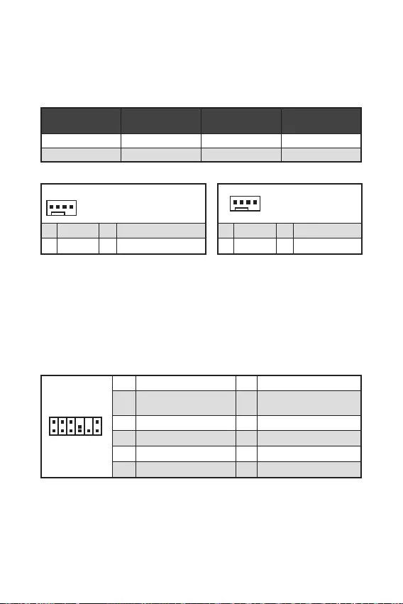
17
1
212
11
1 SPI Power 2 SPI Chip Select
3
Master In Slave Out
(SPI Data)
4
Master Out Slave In
(SPI Data)
5 Reserved 6 SPI Clock
7 Ground 8 SPI Reset
9 Reserved 10 No Pin
11 Reserved 12 Interrupt Request
Dieser Anschluss wird für das TPM Modul (Trusted Platform Module) verwendet.
Weitere Informationen über den Einsatz des optionalen TPM Modules entnehmen Sie
bitte dem TPM Plattform Handbuch.
Diese Anschlüsse können im PWM (Pulse Width Modulation) Modus
oder Spannungsmodus betrieben werden. Im PWM-Modus bieten die
Lüfteranschlüsse konstante 12V Ausgang und regeln die Lüftergeschwindigkeit
per Drehzahlsteuersignal. Im DC-Modus bestimmen die Lüfteranschlüsse die
Lüftergeschwindigkeit durch Ändern der Spannung.
Sie können unter die Lüfterdrehzahl ändern
1
1 Ground 2 +12V
3 Sense 4 Speed Control Signal
CPU_FAN1 PWM mode 2A 24W
SYS_FAN1 DC mode 1A 12W
1
1 Ground 2 Voltage Control
3 Sense 4 NC
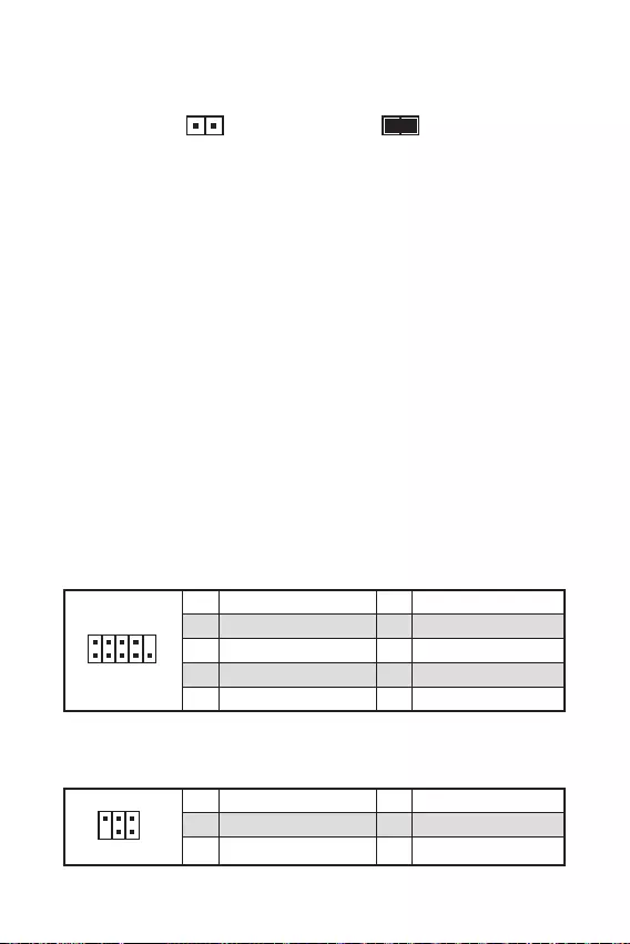
18
Mit diesem Anschluss können Sie das optionale serielle Schnittstelle mit dem
Einbausatze verbinden.
An diesem Anschluss wird ein optionales Tuning Controller-Modul angeschlossen.
1
2 10
9
1 DCD 2 SIN
3 SOUT 4 DTR
5 Ground 6 DSR
7 RTS 8 CTS
9 RI 10 No Pin
1
2 6
5
1 No pin 2 NC
3 MCU_SMB_SCL_M 4 MCU_SMB_SDA_M
5 VCC5 6 Ground
Dieser Anschluss wird mit einem Kontaktschalter verbunden.
Normal
(Standardwert) Löse den Gehäuseeingriff
aus
Schließen Sie den -Anschluss am Gehäusekontakt-Schalter/ Sensor am
Gehäuse an.
Schließen Sie die Gehäuseabdeckung.
Gehen Sie zu .
Stellen Sie auf .
Drücken Sie F10 zum Speichern und Beenden und drücken Sie dann die —
Taste, um Ja auszuwählen.
Bei eingeschaltetem Computer wird eine Warnmeldung auf dem Bildschirm
angezeigt, wenn die Gehäuseabdeckung wieder geöffnet wird.
Gehen Sie zu .
Stellen Sie auf Reset.
Drücken Sie F10 zum Speichern und Beenden und drücken Sie dann die —
Taste, um Ja auszuwählen.
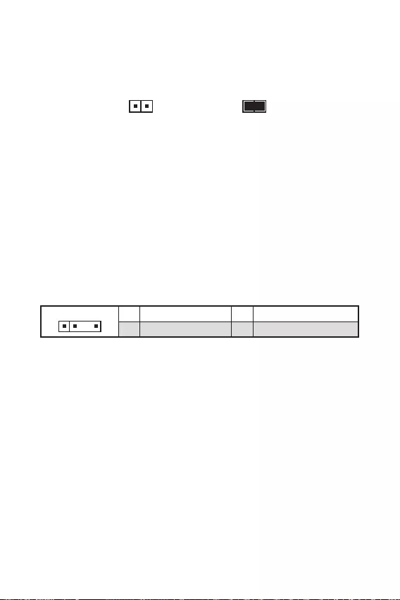
19
JRAINBOW ermöglicht den Anschluss von WS2812B einzeln adressierbaren RGB-
LED-Streifen (5 V).
Schließen Sie nur passende LED-Streifen an. Der JRGB- und der JRAINBOW-
Anschluss verfügen über unterschiedliche Spannungen. Der Anschluss eines 5 V LED-
Streifens an den JRGB-Anschluss führt zu einer Beschädigung des LED-Streifens.
Der JRAINBOW Anschluss unterstützt bis zu 75 LEDs WS2812B einzeln adressier-
bare RGB-LED-Streifen (5 V/ Daten/ Erdung) mit der maximalen Leistung von 3 A (5
V). Bei einer Helligkeit von 20 Prozent unterstützt dieser Anschluss bis zu 200 LEDs.
Schalten Sie die Stromversorgung aus und ziehen Sie das Netzkabel ab, bevor Sie
die RGB-LED-Streifen ein- und ausbauen.
Bitte verwenden Sie die MSI-Software zur Steuerung des LED-Leuchtstreifens.
11 +5V 2 Data
3 No Pin 4 Ground
Der Onboard CMOS Speicher (RAM) wird durch eine externe Spannungsversorgung
durch eine Batterie auf dem Motherboard versorgt, um die Daten der
Systemkonfiguration zu speichern. Wenn Sie die Systemkonfiguration löschen
wollen, müssen Sie die Steckbrücke für kurze Zeit umsetzen.
Daten
beibehalten
(Standardwert)
CMOS-Daten
löschen/ Reset des
BIOS
Schalten Sie den Computer ab und ziehen Sie das Netzkabel ab.
Verwenden Sie eine Steckbrücke, um für 5-10 Sekunden kurzzuschließen.
Entfernen Sie die Steckbrücke von .
Stecken Sie das Kabel Ihres Computers in die Steckdose hinein und schalten Sie
den Computer ein.

20
Mit dem JRGB Anschluss können Sie den 5050 RGB-LED-Streifen (12 V) anschließen.
Der JRGB Anschluss unterstützt bis zu 2 Metern 5050 RGB LED-Streifen (12V/G/
R/B) mit der maximalen Leistung von 3 A (12 V).
Schalten Sie die Stromversorgung aus und ziehen Sie das Netzkabel ab, bevor Sie
die RGB-LED-Streifen ein- und ausbauen.
Bitte verwenden Sie die MSI-Software zur Steuerung des LED-Leuchtstreifens.
11 +12V 2 G
3 R 4 B
Diese LEDs zeigen den Status des Motherboards an.
— DRAM wird nicht erkannt oder ist fehlerhaft.
— GPU wird nicht erkannt oder ist fehlerhaft.
— Boot-Gerät wird nicht erkannt oder ist fehlerhaft.
— CPU wird nicht erkannt oder ist fehlerhaft.

21
Laden Sie die neuesten Treiber und Dienstprogramme von www.msi.com herunter
und aktualisieren Sie sie
Schalten Sie den Computer ein.
Legen Sie die Windows® 10 Disk oder das USB-Flashlaufwerk in das optisches
Laufwerk.
Drücken Sie die Taste auf dem Computergehäuse.
Drücken Sie die F11-Taste während des POST-Vorgangs (Power-On Self Test),
um das Bootmenu zu öffnen.
Wählen Sie das optische Laufwerk aus dem Bootmenu.
Wenn eine entsprechende Meldung
angezeigt wird, drücken Sie eine beliebige Taste.
Folgen Sie den Anweisungen auf dem Bildschirm, um das Dienstprogramm
„Windows® 10“ zu installieren.
Starten Sie Ihren Computer mit Windows® 10.
Legen Sie die MSI® Treiber Disk in das optische Laufwerk.
Klicken Sie auf die Pop-up-Meldung
und wählen Sie aus, um
den Installer zu öffnen. Wenn Sie die AutoPlay-Funktionen in der Windows-
Systemsteuerung ausschalten, können Sie das Programm im
Hauptverzeichnis der MSI Treiber CD auch manuell ausführen.
Der Installer wird findet eine Liste aller benötigten Treiber auf der
-Registerkarte.
Klicken Sie auf in der rechten unteren Ecke des Fensters.
Die Treiber-Installation läuft. Wenn die Installation abgeschlossen ist, werden Sie
dazu aufgefordet, den Computer neu zu starten.
Klicken Sie zum Beenden auf .
Starten Sie Ihren Computer neu.

22
MSI Center ist eine Anwendung, mit der Sie die Spieleinstellungen einfach
optimieren und die Software zur Erstellung von Inhalten einstellen können.
Außerdem können Sie LED-Lichteffekte in PCs und anderen MSI-Produkten
steuern und synchronisieren. Mit MSI Center können Sie ideale Modi einstellen, die
Systemleistung überwachen und die Lüftergeschwindigkeit anpassen.
Wenn Sie weitere Informationen zu MSI Center wünschen, besuchen
Sie bitte
http://download.msi.com/manual/mb/MSICENTER.pdf
oder scannen Sie den QR-Code.
Die Funktionen können je nach Produkt variieren.

23
Das MSI UEFI-BIOS ist mit der UEFI-Architektur (Unified Extensible Firmware
Interface) kompatibel. UEFI hat viele neue Funktionen und besitzt Vorteile, die das
traditionelle BIOS nicht bieten kann. UEFI wird das BIOS in Zukunft vollständig
ersetzen. Das MSI UEFI-BIOS verwendet UEFI als Standard-Startmodus, um die
Funktionen des neuen Chipsatzes voll auszunutzen.
Der Begriff „BIOS“ bezieht sich in diesem Benutzerhandbuch auf das UEFI-BIOS,
sofern nicht anders angegeben.
Schnelles Booten — UEFI kann das Betriebssystem direkt booten und den BIOS-
Selbsttestprozess speichern. Außerdem entfällt die Zeit, um während des POST in
den CSM-Modus zu wechseln.
Unterstützt Festplattenpartitionen, die größer als 2 TB sind.
Unterstützt mehr als 4 primäre Partitionen mit einer GUID-Partitionstabelle (GPT).
Unterstützt eine unbegrenzte Anzahl an Partitionen.
Unterstützt den vollen Funktionsumfang neuer Geräte – neue Geräte bieten
möglicherweise keine Abwärtskompatibilität.
Unterstützt sicheren Start – UEFI kann die Gültigkeit des Betriebssystems
überprüfen, um sicherzustellen, dass keine Malware den Startvorgang
beeinträchtigt.
— Dieses Motherboard unterstützt nur das
64-Bit-Windows 10-Betriebssystem.
Das System erkennt Ihre Grafikkarte. Bei Erkennung einer
nicht kompatiblen Grafikkarte wird die Warnmeldung
erkannt.
Wir empfehlen Ihnen, eine GOP / UEFI-kompatible Grafikkarte zu nutzen oder eine
CPU mit integrierter Grafikeinheit zu verwenden, um eine normale Funktion des
Systems zu gewährleisten.
Schalten Sie den Computer ein.
Während des BOOT-Vorgangs drücken Sie die Taste , wenn die Meldung
erscheint.
Nach dem Aufrufen des BIOS können Sie den oben auf dem
Bildschirm überprüfen.

24
Die Standardeinstellungen bieten die optimale Leistung für die Systemstabilität unter
Normalbedingungen. Sie sollten , um
mögliche Schäden des Systems oder Boot-Fehler zu vermeiden, außer Sie besitzen
ausreichende BIOS Kenntnisse.
BIOS Funktionen werden für eine bessere Systemleistung kontinuierlich aktualis-
iert. Deswegen können die Beschreibungen leicht von der letzten Fassung des BIOS
abweichen und sollten demnach nur als Anhaltspunkte dienen. Für eine Beschrei—
bung der BIOS Funktionen rufen Sie die Informationstafel aus.
Die BIOS-Bildschirme, -Optionen und -Einstellungen variieren je nach System.
Während des BOOT-Vorgangs drücken Sie die Taste , wenn die Meldung
erscheint.
F1: Allgemeine Hilfe
F2: Hinzufügen/Entfernen eines Favoritenpunkts
F3: Öffnen des Favoriten Menüs
F4: Öffnen des Menüs CPU-Spezifikationen
: Öffnen des Memory-Z Menüs
: Laden der ursprünglichen Setup-Standardwerte
F7: Wechselt zwischen dem Erweiterten-Modus und EZ-Modus
F8: OC-Profil wird vom USB-Stick geladen
F9: OC-Profil wird auf einem USB-Stick gespeichert
F10: Speichern oder Zurücksetzen der Änderungen*
F12: Macht einen Screenshot und speichert auf einen FAT/FAT32-USB-Laufwerk.
: Öffnet die Suchseite
* Beim Drücken der F10 Taste wird das Fenster zum Speichern der Einstellungen
angezeigt. Wählen Sie , um die Wahl zu bestätigen, oder , um die derzeitige
Einstellung beizubehalten.
Wenn Sie weitere Anweisungen zur BIOS-Einrichtung wünschen,
lesen Sie bitte
http://download.msi.com/manual/mb/Intel500BIOSde.pdf
oder scannen Sie den QR-Code.

Sie können die Werkseinstellung wieder herstellen, um bestimmte Probleme zu
lösen. Es gibt verschiedene Möglichkeiten, um das BIOS zurückzusetzen:
Öffnen Sie das BIOS und drücken Sie , um optimierten Einstellungen zu laden.
Schließen Sie die an das Motherboard an.
Drücken Sie die auf der Rückseite E/A des Panels.
Bitte lesen Sie für Informationen zum BIOS-Reset im Bereich
nach.
Vorbereitung:
Laden Sie bitte die neueste BIOS Version, die dem Motherboard-Modell entspricht,
Flash-Laufwerk.
BIOS-Aktualisierungsschritte:
Schließen das USB-Flashlaufwerk mit der BIOS-Datei an den Computer.
Bitte folgen Sie den nachfolgenden Schritten, um in den Blitz-Modus zu schalten.
Beim Neustart drücken Sie während des POST-Vorgangs die Taste
und klicken Sie auf tum das System neu zu starten.
Beim Neustart drücken Sie während des POST-Vorgangs die Taste
während des POST-Vorgangs die Taste. Klicken Sie die Taste und
klicken Sie auf tum das System neu zu starten.
Wählen Sie die BIOS-Datei zur Durchführung des BIOS-Aktualisierungsprozesses
aus.
Klicken Sie auf Ja, wenn Sie dazu aufgefordert werden, um die Wiederherstellung
des BIOS zu starten.
Nachdem das Flashen des BIOS vollständig ist, startet das System automatisch
neu.

Vorbereitung:
Stellen Sie sicher, dass zuvor die LAN-Treiber installiert wurden und eine
Internetverbindung eingerichtet ist.
Bitte schließen Sie jegliche andere Anwendungssoftware, bevor Sie das BIOS
aktualisieren.
Schritte zur Aktualisierung des BIOS:
Installieren und starten Sie „MSI DRAGON CENTER“ und gehen Sie zur —
Seite.
Wählen Sie aus und klicken Sie auf die Schaltfläche .
Wählen Sie die BIOS-Datei aus und klicken Sie auf das -Symbol.
Die Installationsanweisung wird angezeigt, klicken Sie daraufhin auf die
Schaltfläche Install.
Das System wird automatisch neu gestartet, um das BIOS zu aktualisieren.
Nachdem das Flashen des BIOS vollständig ist, startet das System automatisch
neu.

1
2
3
8
9
…………………………………………………………………………………..10
……………………………………………………………………………………………….11
……………………………………………………………………………………………….11
……………………………………………………………..11
……………………………………………………….12
……………………………………………………….12
…………………………………………………………………….13
…………………………………………………………………………13
…………………………………………………..14
…………………………………………………………………………15
……………………………………………………………..15
……………………………………………16
………………………………………………………………………..16
………………………………………………………17
……………………………………………………17
……………………………………………………..17
…………………………………..18
…………………………………………………….18
…………………………………………………………………………….19
……………………………………………………………………………..19
20
21
………………………………………………………………………………………….22
………………………………………………………………………………..22
……………………………………………………………………22
…………………………………………………………………………………………………23
………………………………………………………………………………………..23

2

3
Intel® B560
/

4
Realtek® ALC897 Codec

B560M BOMBER)
B560M BOMBER)

NUVOTON NCT6687-R
UEFI AMI BIOS
ACPI 6.2, SMBIOS 3.0
MSI Center
Intel® Extreme Tuning Utility
CPU-Z MSI GAMING
Google Chrome™, Google Toolbar, Google Drive
Norton™ Internet Security Solution
LAN Manager
User Scenario
Hardware Monitor
Frozr AI Cooking
True Color
Live Update
Speed Up
Super Charger

7
Audio Boost
2.5G LAN
LAN Manager
1x M.2 Shield Frozr
Smart Fan Control
Mystic Light SYNC
EZ DEBUG LED
DDR4 Boost
Core Boost
USB3.2 Gen1 5G
PCI-E Steel Armor
Click BIOS 5
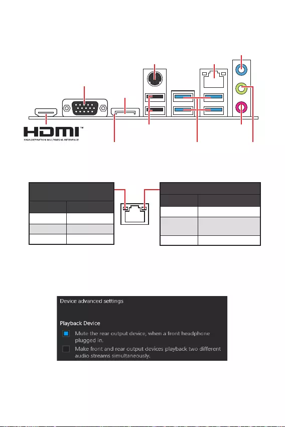
8
USB 2.0 Type-A
DisplayPort
USB 3.2 Gen 1
VGA
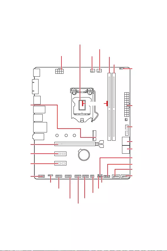
9
BAT1
SYS_FAN1
CPU_FAN1
JRAINBOW1
PCI_E2
M2_1
PCI_E3
PCI_E1
DIMMA1
DIMMB1
JBAT1
JDASH1
SATA5
SATA6
JFP1
JCOM1
JAUD1
ATX_PWR1
CPU_PWR1
JUSB3
JUSB2
JTPM1
JUSB1
JFP2
JCI1
JRGB1
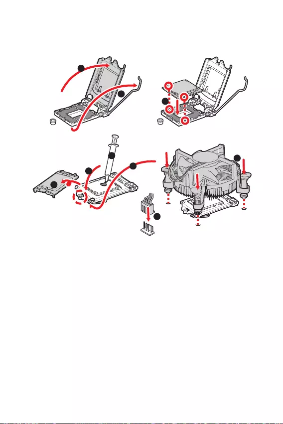
10
1
4
78
9
3
2
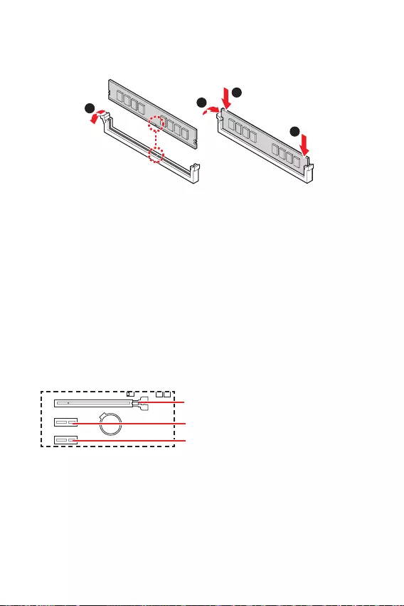
11
.
BAT1
1
2
3
2
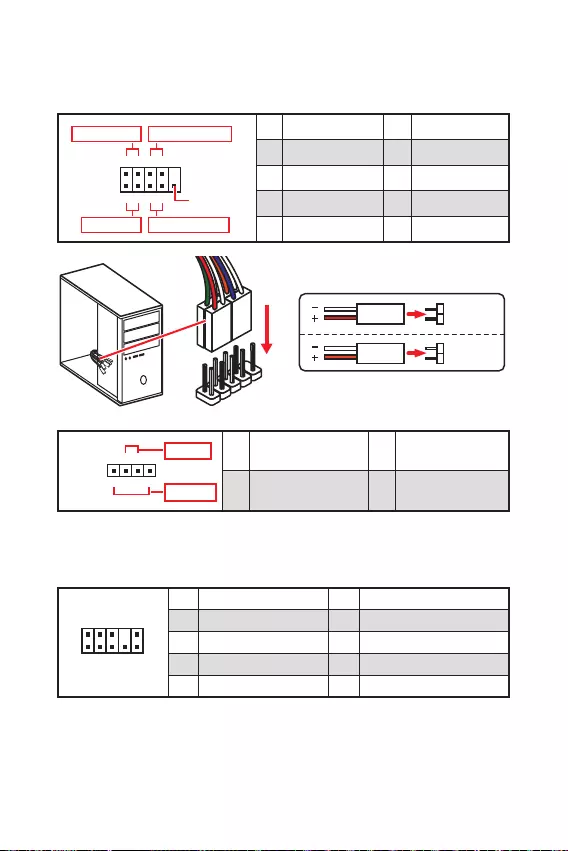
12
1
2 10
9
+
+
+— ——
—
+
Power LED
HDD LED Reset Switch
Reserved
Power Switch 1 HDD LED + 2 Power LED +
3 HDD LED — 4 Power LED —
5 Reset Switch 6 Power Switch
7 Reset Switch 8 Power Switch
9 Reserved 10 No Pin
JFP2 1
+
+—
—
Speaker
Buzzer 1 Speaker — 2 Buzzer +
3 Buzzer — 4 Speaker +
HDD LED
RESET SW
HDD LED HDD LED —
HDD LED +
POWER LED —
POWER LED +
POWER LED
JFP1
1
2 10
9
1 MIC L 2 Ground
3 MIC R 4 NC
5 Head Phone R 6 MIC Detection
7 SENSE_SEND 8 No Pin
9 Head Phone L 10 Head Phone Detection

13
SATA3
SATA1
SATA4
SATA5
SATA6
SATA2
1
3
30º30º
2

14
24
131
12
ATX_PWR1
1 +3.3V 13 +3.3V
2 +3.3V 14 -12V
3 Ground 15 Ground
4 +5V 16 PS-ON#
5 Ground 17 Ground
6 +5V 18 Ground
7 Ground 19 Ground
8 PWR OK 20 Res
9 5VSB 21 +5V
10 +12V 22 +5V
11 +12V 23 +5V
12 +3.3V 24 Ground
5
41
8
CPU_PWR1
1 Ground 5 +12V
2 Ground 6 +12V
3 Ground 7 +12V
4 Ground 8 +12V
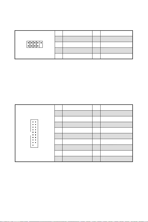
1
10 11
20
1 Power 11 USB2.0+
2 USB3_RX_DN 12 USB2.0-
3 USB3_RX_DP 13 Ground
4 Ground 14 USB3_TX_C_DP
5 USB3_TX_C_DN 15 USB3_TX_C_DN
6 USB3_TX_C_DP 16 Ground
7 Ground 17 USB3_RX_DP
8 USB2.0- 18 USB3_RX_DN
9 USB2.0+ 19 Power
10 Ground 20 No Pin
1
2 10
9
1 VCC 2 VCC
3 USB0- 4 USB1-
5 USB0+ 6 USB1+
7 Ground 8 Ground
9 No Pin 10 NC
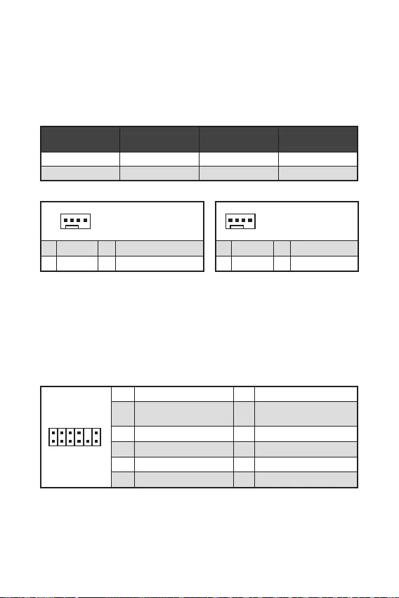
1
212
11
1 SPI Power 2 SPI Chip Select
3
Master In Slave Out
(SPI Data)
4
Master Out Slave In
(SPI Data)
5 Reserved 6 SPI Clock
7 Ground 8 SPI Reset
9 Reserved 10 No Pin
11 Reserved 12 Interrupt Request
1
1 Ground 2 +12V
3 Sense 4 Speed Control Signal
CPU_FAN1
SYS_FAN1
1
1 Ground 2 Voltage Control
3 Sense 4 NC
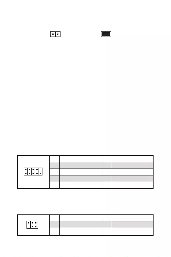
17
.
.
.
F10
.
.
, Reset.
F10
.
1
2 10
9
1 DCD 2 SIN
3 SOUT 4 DTR
5 Ground 6 DSR
7 RTS 8 CTS
9 RI 10 No Pin
1
2 6
5
1 No pin 2 NC
3 MCU_SMB_SCL_M 4 MCU_SMB_SDA_M
5 VCC5 6 Ground
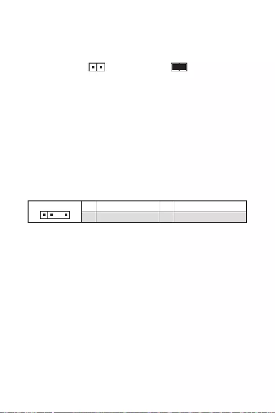
18
.
11 +5V 2 Data
3 No Pin 4 Ground
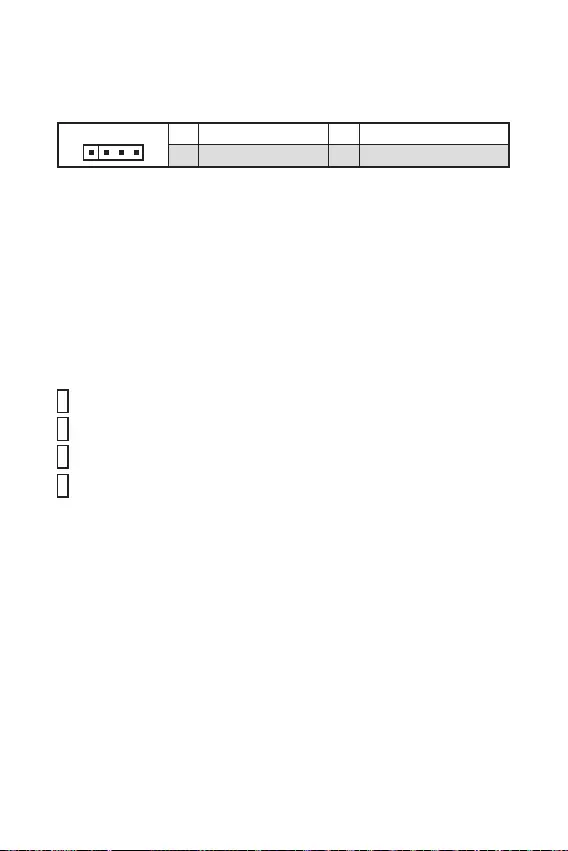
19
11 +12V 2 G
3 R 4 B

20
Windows® 10.
F11
MSI Drive disc.
.
http://download.msi.com/manual/mb/MSICENTER.pdf

21
».

22
.
F1
F2
F3
F4
F7
F8
F9
F10
F12
http://download.msi.com/manual/mb/Intel500BIOSru.pdf

23
BIOS.

24
.
.
.
.

1
2
3
8
…………………………………………………………………………………….8
9
…………………………………………………………………………………………………….10
………………………………………………………………………………………………….11
……………………………………………………………………………..11
…………………………………………………………………………….12
…………………………………………………………………………………..12
…………………………………………………………………………..13
………………………………………………………………………………….13
ATX_PWR1, CPU_PWR1:
………………………………………………………………….14
………………………………………………………………………………..15
…………………………………………………………………15
………………………………………………………………….16
………………………………………………………………………………….16
……………………………………………………………………………….17
………………………………………………………………………………….17
……………………………………………………………………………..17
………………………………………………………………18
………………………………………………………………….18
…………………………………………………………………………………19
………………………………………………………………………………………….19
20
21
……………………………………………………………………………………………………22
…………………………………………………………………………………………….22
…………………………………………………………………………………………….22
……………………………………………………………………………………………………23
……………………………………………………………………………………………………23

2

3
Intel® Core™
*
Intel®
*
CPU)
B560 )
2048×1280 @60Hz, 1920×1200 @60Hz*/**
/
60Hz*/**

4
CPU)
B560 )
6
4
6

BOMBER)
BOMBER)

UEFI AMI BIOS
ACPI 6.2, SMBIOS 3.0
MSI Center
BOMBER)
True Color
Live Update

7
2.5G LAN
1
B560M PRO
B560M BOMBER)
USB3.2 Gen1 5G
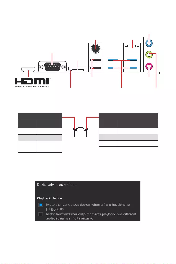
8
2.5 Gbps LAN
USB 2.0 Type-A
USB 3.2 Gen 1
5Gbps Type-A
VGA

9
BAT1
SYS_FAN1
CPU_FAN1
JRAINBOW1
PCI_E2
M2_1
PCI_E3
PCI_E1
DIMMA1
DIMMB1
JBAT1
JDASH1
SATA5
SATA6
JFP1
JCOM1
JAUD1
ATX_PWR1
CPU_PWR1
JUSB3
JUSB2
JTPM1
JUSB1
JFP2
JCI1
JRGB1

10
1
4
78
9
3
2
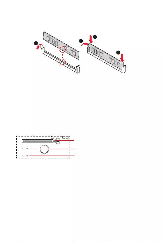
11
BAT1
1
2
3
2

12
1
2 10
9
+
+
+— ——
—
+
Power LED
HDD LED Reset Switch
Reserved
Power Switch 1 HDD LED + 2 Power LED +
3 HDD LED — 4 Power LED —
5 Reset Switch 6 Power Switch
7 Reset Switch 8 Power Switch
9 Reserved 10 No Pin
JFP2 1
+
+—
—
Speaker
Buzzer 1 Speaker — 2 Buzzer +
3 Buzzer — 4 Speaker +
HDD LED
RESET SW
HDD LED HDD LED —
HDD LED +
POWER LED —
POWER LED +
POWER LED
JFP1
1
2 10
9
1 MIC L 2 Ground
3 MIC R 4 NC
5 Head Phone R 6 MIC Detection
7 SENSE_SEND 8 No Pin
9 Head Phone L 10 Head Phone Detection
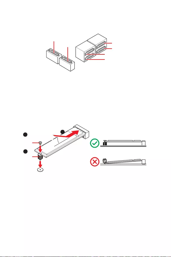
13
SATA3
SATA1
SATA4
SATA5
SATA6
SATA2
1
3
30º30º
2

14
24
131
12
ATX_PWR1
1 +3.3V 13 +3.3V
2 +3.3V 14 -12V
3 Ground 15 Ground
4 +5V 16 PS-ON#
5 Ground 17 Ground
6 +5V 18 Ground
7 Ground 19 Ground
8 PWR OK 20 Res
9 5VSB 21 +5V
10 +12V 22 +5V
11 +12V 23 +5V
12 +3.3V 24 Ground
5
41
8
CPU_PWR1
1 Ground 5 +12V
2 Ground 6 +12V
3 Ground 7 +12V
4 Ground 8 +12V

1
10 11
20
1 Power 11 USB2.0+
2 USB3_RX_DN 12 USB2.0-
3 USB3_RX_DP 13 Ground
4 Ground 14 USB3_TX_C_DP
5 USB3_TX_C_DN 15 USB3_TX_C_DN
6 USB3_TX_C_DP 16 Ground
7 Ground 17 USB3_RX_DP
8 USB2.0- 18 USB3_RX_DN
9 USB2.0+ 19 Power
10 Ground 20 No Pin
1
2 10
9
1 VCC 2 VCC
3 USB0- 4 USB1-
5 USB0+ 6 USB1+
7 Ground 8 Ground
9 No Pin 10 NC
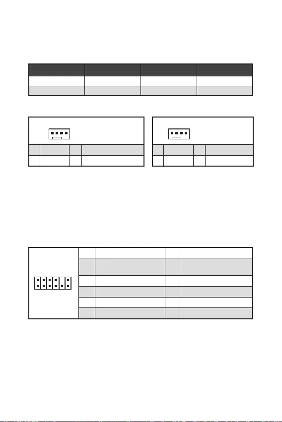
1
212
11
1 SPI Power 2 SPI Chip Select
3
Master In Slave Out
(SPI Data)
4
Master Out Slave In
(SPI Data)
5 Reserved 6 SPI Clock
7 Ground 8 SPI Reset
9 Reserved 10 No Pin
11 Reserved 12 Interrupt Request
1
1 Ground 2 +12V
3 Sense 4 Speed Control Signal
CPU_FAN1 2A 24W
SYS_FAN1 1A 12W
1
1 Ground 2 Voltage Control
3 Sense 4 NC
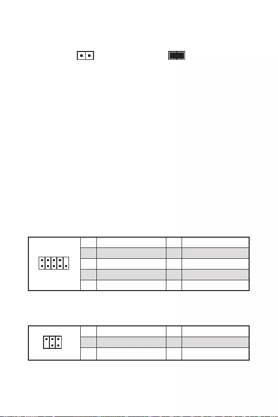
17
F10
Reset
F10
1
2 10
9
1 DCD 2 SIN
3 SOUT 4 DTR
5 Ground 6 DSR
7 RTS 8 CTS
9 RI 10 No Pin
1
2 6
5
1 No pin 2 NC
3 MCU_SMB_SCL_M 4 MCU_SMB_SDA_M
5 VCC5 6 Ground
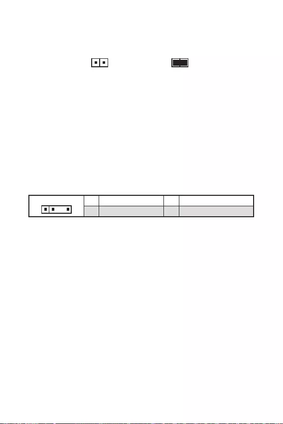
18
BIOS
11 +5V 2 Data
3 No Pin 4 Ground
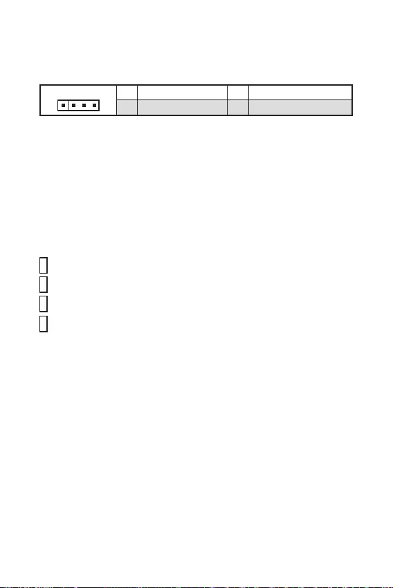
19
11 +12V 2 G
3 R 4 B

20
F11
®
http://download.msi.com/manual/mb/MSICENTER.pdf

21

22
F1
F2
F3
F4
F7
F8
F9
F10
F12:
http://download.msi.com/manual/mb/Intel500BIOSsc.pdf

23

24

1
2
3
8
9
…………………………………………………………………………………………………….10
…………………………………………………………………………………………………11
11
……………………………………………………………………………..11
…………………………………………………………………………….12
……………………………………………………………………………………12
…………………………………………………………………………..13
………………………………………………………………………………….13
ATX_PWR1, CPU_PWR1:
………………………………………………………………….14
………………………………………………………………………………..15
…………………………………………………………………15
……………………………………………………………16
………………………………………………………………………………….16
………………………………………………………………………………………17
……………………………………………………………………………………..17
……………………………………………………………………………..17
……………………………………………………….18
……………………………………………………………….18
………………………………………………………………………………….19
………………………………………………………………………………………….19
20
21
……………………………………………………………………………………………………22
…………………………………………………………………………………………….22
………………………………………………………………………………………….22
……………………………………………………………………………………………………23
……………………………………………………………………………………………………23

2

3
Intel®
JEDEC & POR)
2048×1280 @60Hz, 1920×1200 @60Hz*/**
60Hz*/**

4
B560 )
1

BOMBER)

Micro-ATX
UEFI AMI BIOS
ACPI 6.2, SMBIOS 3.0
MSI Center
Intel® Extreme Tuning Utility
CPU-Z MSI GAMING
Norton™ Internet Security Solution
LAN Manager
User Scenario
Hardware Monitor
Frozr AI Cooling
True Color
Live Update
Speed Up
Super Charger

7
B560M BOMBER)
USB3.2 Gen1 5G
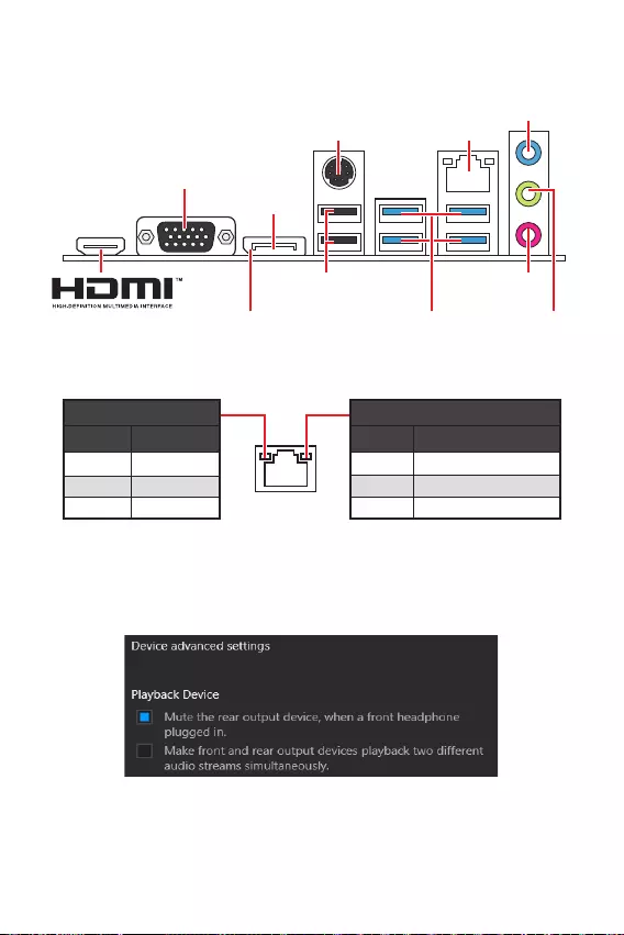
8
USB 2.0 Type-A
DisplayPort
USB 3.2 Gen 1
5Gbps Type-A
VGA

9
BAT1
53.25mm*
SYS_FAN1
CPU_FAN1
JRAINBOW1
PCI_E2
M2_1
PCI_E3
PCI_E1
DIMMA1
DIMMB1
JBAT1
JDASH1
SATA5
SATA6
JFP1
JCOM1
JAUD1
ATX_PWR1
CPU_PWR1
JUSB3
JUSB2
JTPM1
JUSB1
JFP2
JCI1
JRGB1

10
1
4
78
9
3
2
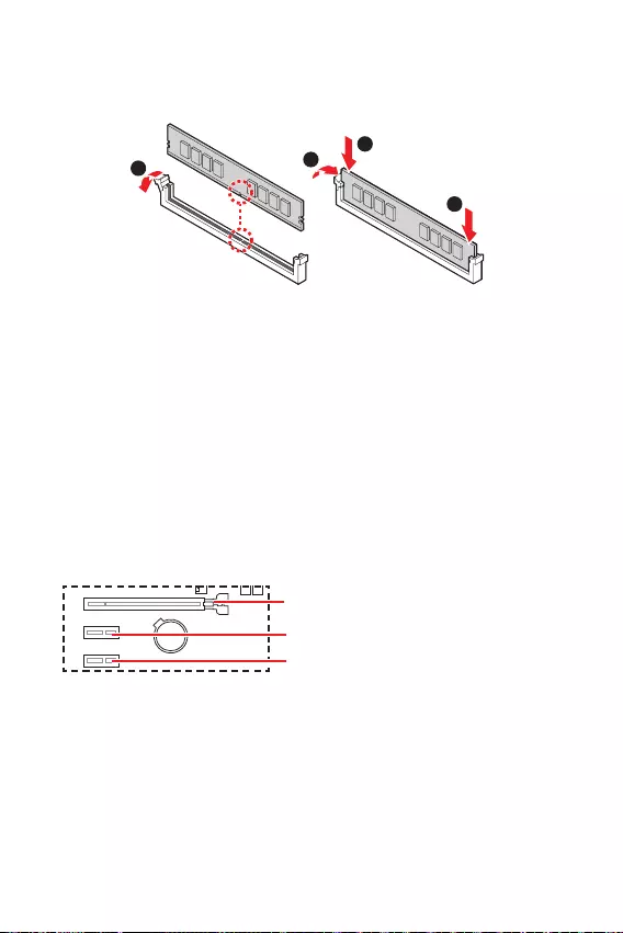
11
BAT1
1
2
3
2

12
1
2 10
9
+
+
+— ——
—
+
Power LED
HDD LED Reset Switch
Reserved
Power Switch 1 HDD LED + 2 Power LED +
3 HDD LED — 4 Power LED —
5 Reset Switch 6 Power Switch
7 Reset Switch 8 Power Switch
9 Reserved 10 No Pin
JFP2 1
+
+—
—
Speaker
Buzzer 1 Speaker — 2 Buzzer +
3 Buzzer — 4 Speaker +
HDD LED
RESET SW
HDD LED HDD LED —
HDD LED +
POWER LED —
POWER LED +
POWER LED
JFP1
1
2 10
9
1 MIC L 2 Ground
3 MIC R 4 NC
5 Head Phone R 6 MIC Detection
7 SENSE_SEND 8 No Pin
9 Head Phone L 10 Head Phone Detection
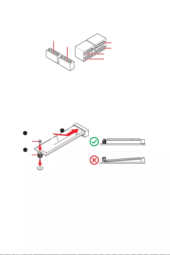
13
SATA3
SATA1
SATA4
SATA5
SATA6
SATA2
1
3
30º30º
2

14
24
131
12
ATX_PWR1
1 +3.3V 13 +3.3V
2 +3.3V 14 -12V
3 Ground 15 Ground
4 +5V 16 PS-ON#
5 Ground 17 Ground
6 +5V 18 Ground
7 Ground 19 Ground
8 PWR OK 20 Res
9 5VSB 21 +5V
10 +12V 22 +5V
11 +12V 23 +5V
12 +3.3V 24 Ground
5
41
8
CPU_PWR1
1 Ground 5 +12V
2 Ground 6 +12V
3 Ground 7 +12V
4 Ground 8 +12V
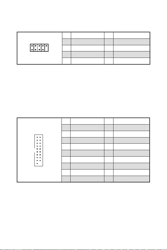
1
10 11
20
1 Power 11 USB2.0+
2 USB3_RX_DN 12 USB2.0-
3 USB3_RX_DP 13 Ground
4 Ground 14 USB3_TX_C_DP
5 USB3_TX_C_DN 15 USB3_TX_C_DN
6 USB3_TX_C_DP 16 Ground
7 Ground 17 USB3_RX_DP
8 USB2.0- 18 USB3_RX_DN
9 USB2.0+ 19 Power
10 Ground 20 No Pin
®
1
2 10
9
1 VCC 2 VCC
3 USB0- 4 USB1-
5 USB0+ 6 USB1+
7 Ground 8 Ground
9 No Pin 10 NC

1
212
11
1 SPI Power 2 SPI Chip Select
3
Master In Slave Out
(SPI Data)
4
Master Out Slave In
(SPI Data)
5 Reserved 6 SPI Clock
7 Ground 8 SPI Reset
9 Reserved 10 No Pin
11 Reserved 12 Interrupt Request
1
1 Ground 2 +12V
3 Sense 4 Speed Control Signal
CPU_FAN1 2A 24W
SYS_FAN1 1A 12W
1
1 Ground 2 Voltage Control
3 Sense 4 NC

17
F10
Reset
1
2 10
9
1 DCD 2 SIN
3 SOUT 4 DTR
5 Ground 6 DSR
7 RTS 8 CTS
9 RI 10 No Pin
1
2 6
5
1 No pin 2 NC
3 MCU_SMB_SCL_M 4 MCU_SMB_SDA_M
5 VCC5 6 Ground
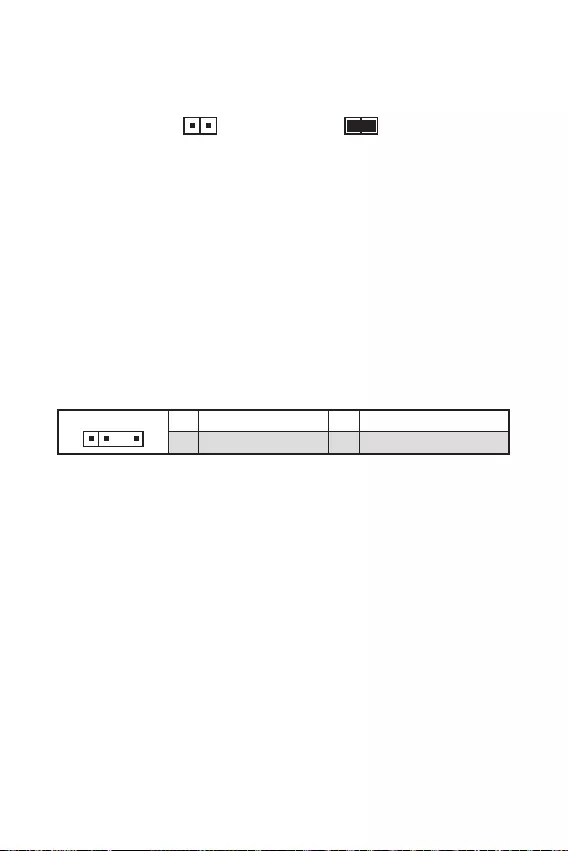
18
11 +5V 2 Data
3 No Pin 4 Ground

19
11 +12V 2 G
3 R 4 B
—
—

20
®
http://download.msi.com/manual/mb/MSICENTER.pdf

21

22
F1:
F2:
F3:
F4:
:
:
F7:
F8:
F9:
F10: *
F12:
:
http://download.msi.com/manual/mb/Intel500BIOStc.pdf

23

24

1
2
3
8
9
…………………………………………………………………………………………………10
………………………………………………………………………………………………11
………………………………………………………………………….11
……………………………………………………………12
…………………………………………………………….. 12
…………………………………………………………………..13
…………………………………………………………………………….13
ATX_PWR1
CPU_PWR1:
………………………………………………………….14
………………………………………………………………………..15
…………………………………………………………15
……………………………………………………….16
………………………………………………………………….16
……………………………………………………………….17
………………………………………………………………….17
………………………………………………17
……………………………………………………18
………………………………………………………..18
………………………………………………………………………….19
EZ Debug LED …………………………………………………………………………………………….19
20
21
…………………………………………………………………………………………………22
………………………………………………………………………….22
…………………………………………………………………………………..22
…………………………………………………………………………………………….23
……………………………………………………………………………….23

2

3
Intel®
)
)
/**
/**
/**

4
)

1 (M-Key)
EZ Debug LED x4

9.3 in. x 8.0 in. (23.6 cm x 20.2 cm)
UEFI AMI BIOS
ACPI 6.2, SMBIOS 3.0
MSI Center
Intel® Extreme Tuning Utility
CPU-Z MSI GAMING
Google Chrome™, Google Toolbar, Google Drive
Norton™ Internet Security Solution
LAN Manager
User Scenario
Hardware Monitor
Frozr AI Cooking
True Color
Live Update
Speed Up
Super Charger

7
Audio Boost
2.5G LAN
M.2 Shield Frozr x1
LED
B560M BOMBER)
Mystic Light SYNC
EZ DEBUG LED
DDR4 Boost
Core Boost
USB3.2 Gen1 5G
PCI-E Steel Armor
Click BIOS 5
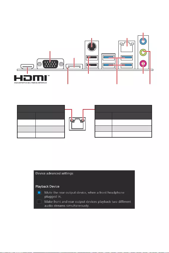
8
Off
Off 10 Mbps
100/ 1000 Mbps
2.5 Gbps
2.5 Gbps LAN
USB 2.0 Type-A
DisplayPort
USB 3.2 Gen 1
5Gbps Type-A
VGA

9
BAT1
53.25mm*
SYS_FAN1
CPU_FAN1
JRAINBOW1
PCI_E2
M2_1
PCI_E3
PCI_E1
DIMMA1
DIMMB1
JBAT1
JDASH1
SATA5
SATA6
JFP1
JCOM1
JAUD1
ATX_PWR1
CPU_PWR1
JUSB3
JUSB2
JTPM1
JUSB1
JFP2
JCI1
JRGB1

10
1
4
78
9
3
2

11
BAT1
1
2
3
2

12
1
2 10
9
+
+
+— ——
—
+
Power LED
HDD LED Reset Switch
Reserved
Power Switch 1 HDD LED + 2 Power LED +
3 HDD LED — 4 Power LED —
5 Reset Switch 6 Power Switch
7 Reset Switch 8 Power Switch
9 Reserved 10 No Pin
JFP2 1
+
+—
—
Speaker
Buzzer 1 Speaker — 2 Buzzer +
3 Buzzer — 4 Speaker +
HDD LED
RESET SW
HDD LED HDD LED —
HDD LED +
POWER LED —
POWER LED +
POWER LED
JFP1
1
2 10
9
1 MIC L 2 Ground
3 MIC R 4 NC
5 Head Phone R 6 MIC Detection
7 SENSE_SEND 8 No Pin
9 Head Phone L 10 Head Phone Detection

13
SATA3
SATA1
SATA4
SATA5
SATA6
SATA2
1
3
30º30º
2

14
24
131
12
ATX_PWR1
1 +3.3V 13 +3.3V
2 +3.3V 14 -12V
3 Ground 15 Ground
4 +5V 16 PS-ON#
5 Ground 17 Ground
6 +5V 18 Ground
7 Ground 19 Ground
8 PWR OK 20 Res
9 5VSB 21 +5V
10 +12V 22 +5V
11 +12V 23 +5V
12 +3.3V 24 Ground
5
41
8
CPU_PWR1
1 Ground 5 +12V
2 Ground 6 +12V
3 Ground 7 +12V
4 Ground 8 +12V

1
10 11
20
1 Power 11 USB2.0+
2 USB3_RX_DN 12 USB2.0-
3 USB3_RX_DP 13 Ground
4 Ground 14 USB3_TX_C_DP
5 USB3_TX_C_DN 15 USB3_TX_C_DN
6 USB3_TX_C_DP 16 Ground
7 Ground 17 USB3_RX_DP
8 USB2.0- 18 USB3_RX_DN
9 USB2.0+ 19 Power
10 Ground 20 No Pin
1
2 10
9
1 VCC 2 VCC
3 USB0- 4 USB1-
5 USB0+ 6 USB1+
7 Ground 8 Ground
9 No Pin 10 NC
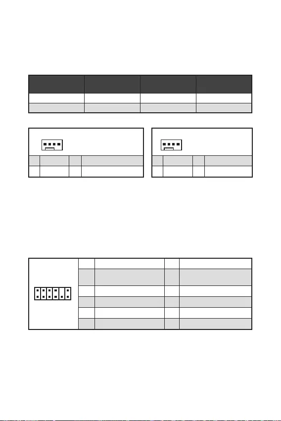
1
212
11
1 SPI Power 2 SPI Chip Select
3
Master In Slave Out
(SPI Data)
4
Master Out Slave In
(SPI Data)
5 Reserved 6 SPI Clock
7 Ground 8 SPI Reset
9 Reserved 10 No Pin
11 Reserved 12 Interrupt Request
1
1 Ground 2 +12V
3 Sense 4 Speed Control Signal
CPU_FAN1 2A 24W
SYS_FAN1 1A 12W
1
1 Ground 2 Voltage Control
3 Sense 4 NC

17
F10
Reset
F10
1
2 10
9
1 DCD 2 SIN
3 SOUT 4 DTR
5 Ground 6 DSR
7 RTS 8 CTS
9 RI 10 No Pin
1
2 6
5
1 No pin 2 NC
3 MCU_SMB_SCL_M 4 MCU_SMB_SDA_M
5 VCC5 6 Ground

18
11 +5V 2 Data
3 No Pin 4 Ground

19
11 +12V 2 G
3 R 4 B
—

20
F11
http://download.msi.com/manual/mb/MSICENTER.pdf

21

22
F1:
F2:
F3:
F4:
:
: O
F7:
F8:
F9:
F10: *
F12:
http://download.msi.com/manual/mb/Intel500BIOSjp.pdf

23

24
Note: This equipment has been tested and
found to comply with the limits for a Class B
digital device, pursuant to part 15 of the FCC
Rules. These limits are designed to provide
reasonable protection against harmful
interference in a residential installation.
This equipment generates, uses and can
radiate radio frequency energy and, if not
installed and used in accordance with the
instructions, may cause harmful interference
to radio communications. However, there is
no guarantee that interference will not occur
in a particular installation. If this equipment
does cause harmful interference to radio or
television reception, which can be determined
by turning the equipment off and on, the user is
encouraged to try to correct the interference by
one or more of the following measures:
Reorient or relocate the receiving antenna.
Increase the separation between the
equipment and receiver.
Connect the equipment into an outlet on
a circuit different from that to which the
receiver is connected.
Consult the dealer or an experienced radio/TV
technician for help.
Caution: Changes or modifications not
expressly approved by the party responsible for
compliance could void the user’s authority to
operate the equipment.
Tested to comply with FCC standards
FOR HOME OR OFFICE USE
This device complies with part 15 of the FCC
Rules. Operation is subject to the following two
conditions:
(1) This device may not cause harmful
interference, and (2) this device must accept any
interference received, including interference
that may cause undesired operation.
Products bearing the CE marking
comply with one or more of the
following EU Directives as may be
applicable:
RED 2014/53/EU; Low Voltage Directive 2014/35/
EU; EMC Directive 2014/30/EU; RoHS Directive
2011/65/EU.
Compliance with these directives is assessed
using applicable European Harmonized
Standards. The point of contact for regulatory
matters is MSI, MSI-NL Eindhoven 5706 5692
ER Son.
10-7D20
B560MAPRO
B560BMBR
European Union:
Batteries, battery packs, and
accumulators should not be
disposed of as unsorted household
waste. Please use the public
collection system to return, recycle,
or treat them in compliance with the
local regulations.
Taiwan:
For better environmental protection,
waste batteries should be collected
separately for recycling or special
disposal.
California, USA:
The button cell battery may contain
perchlorate material and requires
special handling when recycled or
disposed of in California.
For further information please visit:
http://www.dtsc.ca.gov/hazardouswaste/
perchlorate/
CAUTION: There is a risk of explosion, if battery
is incorrectly replaced.
Replace only with the same or equivalent type
recommended by the manufacturer.

ENGLISH
To protect the global environment
and as an environmentalist, MSI
must remind you that…
Under the European Union (“EU”)
Directive on Waste Electrical and
Electronic Equipment, Directive
2002/96/EC, which takes effect
on August 13, 2005, products of
“electrical and electronic equipment” cannot be
discarded as municipal wastes anymore, and
manufacturers of covered electronic equipment
will be obligated to take back such products at
the end of their useful life. MSI will comply with
the product take back requirements at the end
of life of MSI-branded products that are sold into
the EU. You can return these products to local
collection points.
DEUTSCH
Hinweis von MSI zur Erhaltung und Schutz
unserer Umwelt
Gemäß der Richtlinie 2002/96/EG über
Elektro- und Elektronik-Altgeräte dürfen
Elektro- und Elektronik-Altgeräte nicht
mehr als kommunale Abfälle entsorgt
werden. MSI hat europaweit verschiedene
Sammel- und Recyclingunternehmen
beauftragt, die in die Europäische Union
in Verkehr gebrachten Produkte, am Ende
seines Lebenszyklus zurückzunehmen. Bitte
entsorgen Sie dieses Produkt zum gegebenen
Zeitpunkt ausschliesslich an einer lokalen
Altgerätesammelstelle in Ihrer Nähe.
FRANÇAIS
En tant qu’écologiste et afin de protéger
l’environnement, MSI tient à rappeler ceci…
Au sujet de la directive européenne (EU) relative
aux déchets des équipement électriques et
électroniques, directive 2002/96/EC, prenant
effet le 13 août 2005, que les produits
électriques et électroniques ne peuvent être
déposés dans les décharges ou tout simplement
mis à la poubelle. Les fabricants de ces
équipements seront obligés de récupérer
certains produits en fin de vie. MSI prendra en
compte cette exigence relative au retour des
produits en fin de vie au sein de la communauté
européenne. Par conséquent vous pouvez
retourner localement ces matériels dans les
points de collecte.
ESPAÑOL
MSI como empresa comprometida con la
protección del medio ambiente, recomienda:
Bajo la directiva 2002/96/EC de la Unión
Europea en materia de desechos y/o equipos
electrónicos, con fecha de rigor desde el 13 de
agosto de 2005, los productos clasificados como
“eléctricos y equipos electrónicos” no pueden
ser depositados en los contenedores habituales
de su municipio, los fabricantes de equipos
electrónicos, están obligados a hacerse cargo
de dichos productos al termino de su período de
vida. MSI estará comprometido con los términos
de recogida de sus productos vendidos en la
Unión Europea al final de su periodo de vida.
Usted debe depositar estos productos en el
punto limpio establecido por el ayuntamiento
de su localidad o entregar a una empresa
autorizada para la recogida de estos residuos.
NEDERLANDS
Om het milieu te beschermen, wil MSI u eraan
herinneren dat….
De richtlijn van de Europese Unie (EU) met
betrekking tot Vervuiling van Electrische en
Electronische producten (2002/96/EC), die op
13 Augustus 2005 in zal gaan kunnen niet meer
beschouwd worden als vervuiling. Fabrikanten
van dit soort producten worden verplicht om
producten retour te nemen aan het eind van
hun levenscyclus. MSI zal overeenkomstig de
richtlijn handelen voor de producten die de
merknaam MSI dragen en verkocht zijn in de EU.
Deze goederen kunnen geretourneerd worden
op lokale inzamelingspunten.

SRPSKI
mora da vas podesti da…
2002/96/EC, koja stupa na snagu od 13. Avgusta
2005, proizvodi koji spadaju pod “elektronsku i
proizvoda kojima je istekao vek trajanja, koji
imaju MSI oznaku i koji su prodati u EU. Ove
za prikupljanje.
POLSKI
elektronicznych (Dyrektywa 2002/96/EC), która
(sprzedawane na terenie Unii Europejskiej)
zbiorczych.
TÜRKÇE
itibaren geçerli olmak üzere, elektrikli ve
sonra ürünleri geri toplamakla yükümlü
EC platné od 13. srpna 2005 je zakázáno
likvidovat “elektrické a elektronické výrobky”
MAGYAR
Annak érdekében, hogy környezetünket
az MSI emlékezteti Önt, hogy …
Az Európai Unió („EU”) 2005. augusztus 13-án
berendezések hulladékairól szóló 2002/96/
EK irányelve szerint az elektromos és
elektronikus berendezések többé nem
elektronikus berendezések gyártói kötelessé
válnak az ilyen termékek visszavételére
azok hasznos élettartama végén. Az MSI
betartja a termékvisszavétellel kapcsolatos
követelményeket az MSI márkanév alatt az EU-n
belül értékesített termékek esetében, azok
élettartamának végén. Az ilyen termékeket a
ITALIANO
Per proteggere l’ambiente, MSI, da sempre
amica della natura, ti ricorda che….
In base alla Direttiva dell’Unione Europea
(EU) sullo Smaltimento dei Materiali Elettrici
ed Elettronici, Direttiva 2002/96/EC in vigore
dal 13 Agosto 2005, prodotti appartenenti alla
categoria dei Materiali Elettrici ed Elettronici
non possono più essere eliminati come rifiuti
municipali: i produttori di detti materiali saranno
obbligati a ritirare ogni prodotto alla fine del
suo ciclo di vita. MSI si adeguerà a tale Direttiva
ritirando tutti i prodotti marchiati MSI che sono
stati venduti all’interno dell’Unione Europea alla
fine del loro ciclo di vita. È possibile portare i
prodotti nel più vicino punto di raccolta

https://storage-asset.msi.com/html/popup/csr/
cemm_jp.html
This product complies with the “India
E-waste (Management and Handling) Rule
2011” and prohibits use of lead, mercury,
hexavalent chromium, polybrominated
biphenyls or polybrominated diphenyl ethers in
concentrations exceeding 0.1 weight % and 0.01
weight % for cadmium, except for the exemptions
set in Schedule 2 of the Rule.
Uygundur
The product has been designed
to enable proper reuse of parts
and recycling and should not be
thrown away at its end of life.
Users should contact the local
authorized point of collection
for recycling and disposing of their end-of-life
products.
Visit the MSI website and locate a nearby
distributor for further recycling information.
Users may also reach us at gpcontdev@
msi.com for information regarding proper
Disposal, Take-back, Recycling, and
Disassembly of MSI products.
In compliance with chemical substances
regulations, such as the EU REACH Regulation
(Regulation EC No. 1907/2006 of the European
Parliament and the Council), MSI provides
the information of chemical substances in
products at:
https://storage-asset.msi.com/html/popup/csr/
evmtprtt_pcm.html
Micro-Star Int’l Co.,Ltd.
Copyright © 2021 All rights reserved.
The MSI logo used is a registered trademark of
Micro-Star Int’l Co., Ltd. All other marks and
names mentioned may be trademarks of their
respective owners. No warranty as to accuracy
or completeness is expressed or implied. MSI
reserves the right to make changes to this
document without prior notice.
Version 1.0, 2021/02, First release.
If a problem arises with your system and no
solution can be obtained from the user guide,
please contact your place of purchase or
local distributor. Alternatively, please try the
following help resources for further guidance.
Visit the MSI website for technical guide,
BIOS updates, driver updates, and other
information: http://
Register your product at: http://
(Pb)
(Hg)
(Cd)
(Cr(VI))
(PBB)
(PBDE)
(Pb)
(Hg)
(Cd)
(Cr+6)
(PBB)
(PBDE)
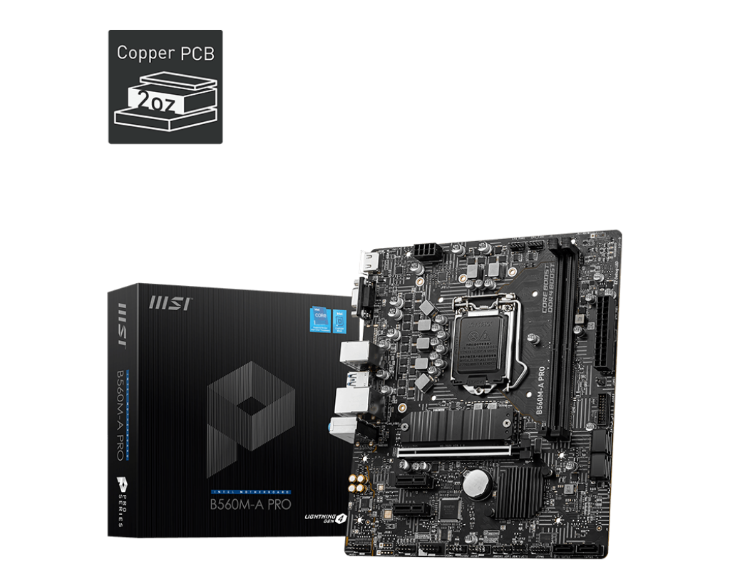
B560M-A PRO
- 基本
- 详细
- Datasheet
- CPU (最高支持)
- CPU 插槽
- 芯片组
- DDR4 内存
- 内存插槽数
- 最大内存 (GB)
- M.2 接口
- 串口 (前置)
- PCI-E Gen
- USB 3.2 ports (Front)
- PCI-E X1
- USB 3.2 ports (Rear)
- PCI-E X16
- USB 2.0 接口 (前置)
- USB 2.0 接口 (背板)
- SATAIII 接口
- 网卡接口
- TPM
- 音频接口 (背板)
- VGA
- HDMI 接口
- DirectX
- 尺寸规格
5200(OC) / 5066(OC) / 5000(OC) / 4800(OC) / 4600(OC) / 4533(OC) / 4400(OC) / 4266(OC) / 4000(OC) / 3866(OC) / 3733(OC) / 3600(OC) / 3466(OC) / 3333(OC) / 3200(JEDCE & POR) / 3000(JEDCE & POR) / 2933(JEDCE & POR) / 2800(JEDCE & POR) / 2666(JEDCE & POR) / 2400(JEDCE & POR) / 2133(JEDCE & POR) MHz
1x Realtek® 8125B 2.5Gbps LAN controller
Intel, the Intel Logo, Intel Inside, Intel Core, and Core Inside are trademarks of Intel Corporation or its subsidiaries in the U.S. and/or other countries.
词语 HDMI™、HDMI™ High-Definition Multimedia Interface(高清晰度多媒体接口)、HDMI™ 商业外观和 HDMI™ 徽标均为 HDMI™ Licensing Administrator, Inc. 的商标或注册商标。
MSI, MSI gaming, dragon, and dragon shield names and logos, as well as any other MSI service or product names or logos displayed on the MSI website, are registered trademarks or trademarks of MSI. The names and logos of third party products and companies shown on our website and used in the materials are the property of their respective owners and may also be trademarks. MSI trademarks and copyrighted materials may be used only with written permission from MSI. Any rights not expressly granted herein are reserved.
所有图片和描述仅用于说明目的。产品的视觉表现可能不完全准确。产品规格、功能和外观可能因型号和国家/地区而异。所有规格如有变更,恕不另行通知。尽管我们尽力在发布时提供最准确和最全面的信息,但少数项目可能包含版面设计或摄影错误。部分产品和配置可能不适用于所有市场,或上市时间有所不同。我们建议您与您当地的供应商核实确切的报价和详细规格。
| Общее количество интерфейсов USB
Общее количество интерфейсов USB USB (Universal Serial Bus — универсальная последовательная шина) — самый распространенный на сегодня интерфейс передачи данных для периферийных устройств, таких как мышки, клавиатуры, принтеры и многое другое. X |
12 |
| Количество интерфейсов USB на задней панели
Количество интерфейсов USB на задней панели USB (Universal Serial Bus — универсальная последовательная шина) — самый распространенный на сегодня интерфейс передачи данных для периферийных устройств, таких как мышки, клавиатуры, принтеры и многое другое. X |
6 |
| Общее количество интерфейсов USB 3.0
Общее количество интерфейсов USB 3.0 USB 3.0 — интерфейс, обеспечивающий теоретическую передачу данных до 5 Гбит/с. Следует отметить, что на практике очень редко получается найти устройства с такой фактической пропускной способностью. Является развитием стандарта USB 2.0 и полностью совместим с предыдущими версиями USB (1.0, 1.1. 2.0). X |
0 |
| Количество интерфейсов USB 3.0 на задней панели
Количество интерфейсов USB 3.0 на задней панели USB 3.0 — интерфейс, обеспечивающий теоретическую передачу данных до 5 Гбит/с. Следует отметить, что на практике очень редко получается найти устройства с такой фактической пропускной способностью. Является развитием стандарта USB 2.0 и полностью совместим с предыдущими версиями USB (1.0, 1.1. 2.0). X |
4 |
| Общее количество интерфейсов FireWire (IEEE1394a)
Общее количество интерфейсов FireWire (IEEE1394a) Firewire — интерфейс, предназначенный для обмена информацией между компьютером и различными электронными устройствами. X |
0 |
| Количество интерфейсов FireWire (IEEE1394a) на задней панели
Количество интерфейсов FireWire (IEEE1394a) на задней панели Firewire — интерфейс, предназначенный для обмена информацией между компьютером и различными электронными устройствами. X |
0 |
| Общее количество интерфейсов FireWire (IEEE1394b)
Общее количество интерфейсов FireWire (IEEE1394b) Firewire — интерфейс, предназначенный для обмена информацией между компьютером и различными электронными устройствами. X |
0 |
| Количество интерфейсов FireWire (IEEE1394b) на задней панели
Количество интерфейсов FireWire (IEEE1394b) на задней панели Firewire — интерфейс, предназначенный для обмена информацией между компьютером и различными электронными устройствами. X |
0 |
| Количество разъемов Thunderbolt на задней панели
Количество разъемов Thunderbolt на задней панели Thunderbolt — интерфейс, предназначенный для подключения периферийных устройств к компьютеру. Скорость передачи данных до 20 Гбит/с. X |
0 |
| Выход S/PDIF
Выход S/PDIF S/PDIF (Sony/Philips Digital Interface) — интерфейс, предназначенный для передачи аудиосигнала без преобразования в аналоговый сигнал, что позволяет избежать потерь в качестве. Используется для подключения акустических систем. X |
нет |
| Общее количество COM-портов
Общее количество COM-портов COM-порт (serial port — последовательный порт, COM-порт от англ. communications port) – порт, используемый для подключения к компьютеру мобильных телефонов и других периферийных устройств. В настоящее время используется очень редко из-за низкой скорости передачи данных. X |
0 |
| Количество COM-портов на задней панели
Количество COM-портов на задней панели COM-порт (serial port — последовательный порт, COM-порт от англ. communications port) – порт, используемый для подключения к компьютеру мобильных телефонов и других периферийных устройств. В настоящее время используется очень редко из-за низкой скорости передачи данных. X |
0 |
| Интерфейс GAME/MIDI
Интерфейс GAME/MIDI GAME/MIDI (Musical Instrument Digital Interface — цифровой интерфейс музыкальных инструментов) — интерфейс для подключения игровых манипуляторов, а также устройства с MIDI-интерфейсом, (синтезаторы). X |
нет |
| Интерфейс LPT
Интерфейс LPT LPT (Line Print Terminal) — параллельный интерфейс, предназначенный для подключения периферийных устройств к компьютеру. В основном, используется для подключения принтеров и других внешних устройств. Также может применяться для организации сети между компьютерами, программирования микроконтроллеров и пр.. X |
нет |
| Интерфейс LPT на задней панели
Интерфейс LPT на задней панели LPT (Line Print Terminal) — параллельный интерфейс, предназначенный для подключения периферийных устройств к компьютеру. В основном, используется для подключения принтеров и других внешних устройств. Также может применяться для организации сети между компьютерами, программирования микроконтроллеров и пр.. X |
нет |
| Компонентный видеовыход на задней панели
Компонентный видеовыход на задней панели Компонентный видеовыход используется для передачи аналогового видеосигнала. Интерфейс обычно выглядит как 3 порта RCA («тюльпан»). Позволяет обмениваться информацией со старыми видеоустройствами. X |
нет |
| Интерфейс D-Sub (VGA) на задней панели
Интерфейс D-Sub (VGA) на задней панели D-Sub (VGA) используется для передачи аналогового видеосигнала на монитор. При передаче данных возможно наличие шумов на видео. На данный момент устарел, используется для совместимости со старыми устройствами вывода видеоинформации (мониторы, проекторы и пр.). X |
есть |
| Интерфейс DVI на задней панели
Интерфейс DVI на задней панели DVI (Digital Visual Interface – цифровой видео интерфейс) используется для передачи цифрового видеосигнала на устройства вывода (мониторы, проекторы и пр.). На видео нет помех и шумов. X |
нет |
| Интерфейс DisplayPort
Интерфейс DisplayPort DisplayPort — стандарт интерфейса для передачи аудио и видео сигналов на цифровые дисплеи (в основном на мониторы). Displayport имеет на данный момент самую большую пропускную способность, но в большинстве случаев это ни к чему. DisplayPort использовался для передачи видеосигнала в Mac устройствах, но вскоре был вытеснен интерфейсом Thunderbolt (имеющим одинаковый с DisplayPort внешний вид и обратную совместимость). Сейчас в основном устанавливается на профессиональных видеокартах (для работы с графикой). X |
есть |
| Интерфейс HDMI на задней панели
Интерфейс HDMI на задней панели HDMI (High Definition Multimedia Interface – мультимедиа интерфейс высокой четкости) используется для передачи цифровых сигналов видео и аудио через единый кабель. В основном применяется для подключения к телевизорам. Поддерживает защиту от нелегального копирования. X |
есть |
| Количество интерфейсов eSATA на задней панели
Количество интерфейсов eSATA на задней панели eSATA (External SATA – внешний SATA) — последовательный интерфейс передачи данных, предназначенный для подключения внешних устройств, в основном, жестких дисков. Аналогичен интерфейсу SATA II, но отличается формой коннектора и расположен на задней панели. Поддерживает режим «горячей замены», скорость передачи данных до 3 Гбит/с. X |
0 |
| Количество интерфейсов eSATAp на задней панели
Количество интерфейсов eSATAp на задней панели eSATAp — комбинированный интерфейс eSATA и USB. Позволяет подключать как устройства с eSATA коннектором, так и с USB. X |
0 |
| Интерфейс PS/2 для клавиатуры
Интерфейс PS/2 для клавиатуры PS/2 — порт, предназначенный для подключения клавиатуры и мыши. На данный момент устарел (вытеснен USB), используется для совместимости со старыми клавиатурами и мышками. X |
есть |
| Интерфейс PS/2 для мыши
Интерфейс PS/2 для мыши PS/2 — порт, предназначенный для подключения клавиатуры и мыши. На данный момент устарел (вытеснен USB), используется для совместимости со старыми клавиатурами и мышками. X |
есть |
| Интерфейс PS/2 для клавиатуры на задней панели
Интерфейс PS/2 для клавиатуры на задней панели PS/2 — порт, предназначенный для подключения клавиатуры и мыши. На данный момент устарел (вытеснен USB), используется для совместимости со старыми клавиатурами и мышками. X |
есть |
| Интерфейс PS/2 для мыши на задней панели
Интерфейс PS/2 для мыши на задней панели PS/2 — порт, предназначенный для подключения клавиатуры и мыши. На данный момент устарел (вытеснен USB), используется для совместимости со старыми клавиатурами и мышками. X |
есть |
| Коаксиальный выход на задней панели
Коаксиальный выход на задней панели Коаксиальный выход на задней панели — интерфейс для передачи цифрового аудиосигнала. X |
нет |
| Оптический выход на задней панели
Оптический выход на задней панели Оптический выход на задней панели — интерфейс для передачи цифрового аудиосигнала. В отличие от коаксиального интерфейса для передачи сигнала используется свет, что позволяет защитить его от электромагнитных помех. X |
нет |
Инструкция
Посмотреть инструкция для MSI B560M-A PRO бесплатно. Руководство относится к категории объективы, 1 человек(а) дали ему среднюю оценку 7.5. Руководство доступно на следующих языках: английский. У вас есть вопрос о MSI B560M-A PRO или вам нужна помощь?
Задайте свой вопрос здесь
Часто задаваемые вопросы
Не можете найти ответ на свой вопрос в руководстве? Вы можете найти ответ на свой вопрос ниже, в разделе часто задаваемых вопросов о MSI B560M-A PRO.
Какой вес MSI B560M-A PRO?
MSI B560M-A PRO имеет вес 776 g.
Какая высота MSI B560M-A PRO?
MSI B560M-A PRO имеет высоту 60 mm.
Какая ширина MSI B560M-A PRO?
MSI B560M-A PRO имеет ширину 236 mm.
Какая толщина MSI B560M-A PRO?
MSI B560M-A PRO имеет толщину 202 mm.
Какой тип USB-подключения MSI B560M-A PRO имеет?
MSI B560M-A PRO имеет USB тип-A подключение.
Инструкция MSI B560M-A PRO доступно в русский?
К сожалению, у нас нет руководства для MSI B560M-A PRO, доступного в русский. Это руководство доступно в английский.
Не нашли свой вопрос? Задайте свой вопрос здесь
Обзор игры Evil lands на Андроид: сражайтесь с темнотой в этой захватывающей ролевой игре
На чтение8 мин
Опубликовано
Обновлено
BIOS (Basic Input/Output System) – это системное программное обеспечение, которое управляет базовыми операциями компьютера. Настройка BIOS является важным шагом для оптимизации работы компьютера и доступа к его возможностям. В данной инструкции мы рассмотрим процесс настройки BIOS на материнской плате MSI MAG B560M MORTAR.
Перед началом процесса настройки BIOS, рекомендуется ознакомиться с руководством пользователя материнской платы MSI MAG B560M MORTAR. В нем вы найдете подробную информацию о различных разделах BIOS и их функциях.
В первую очередь, необходимо включить компьютер и нажать определенную клавишу (обычно Delete или F2) для входа в BIOS. Исходя из модели материнской платы, вам понадобится определенная клавиша для входа в BIOS. Настройки BIOS обычно отображаются на экране при загрузке компьютера.
После входа в BIOS, вы попадете в основное меню. Здесь вы можете видеть информацию о вашей системе, такую как тип процессора, объем оперативной памяти, информацию о жестком диске и другие параметры. Используйте клавиши со стрелками, чтобы перемещаться по меню BIOS. Обратите внимание на разделы, которые содержат информацию о частоте работы процессора, напряжении, оперативной памяти и других важных параметрах.
Содержание
- Что такое BIOS и какое значение оно имеет для компьютера
- Основные функции BIOS на материнской плате MSI MAG B560M MORTAR
- Загрузка и настройка BIOS
- Настройка параметров процессора в BIOS
- Настройка памяти в BIOS
- Настройка графического адаптера в BIOS
- Настройка накопителей и портов в BIOS
- Сохранение и выход из BIOS
Tакже, BIOS предоставляет базовый интерфейс для взаимодействия с аппаратными устройствами, например, клавиатурой и мышью, и обеспечивает загрузку операционной системы.
BIOS содержит набор настроек и параметров, которые позволяют пользователю изменять конфигурацию и производительность компьютера. Это включает такие опции, как порядок загрузки устройств, настройки памяти, частоту процессора и настройки энергосбережения.
Кроме того, BIOS является обновляемым, что позволяет производителю вносить исправления и улучшения в функциональность материнской платы после ее выпуска.
Без BIOS компьютер не будет работать, так как он не сможет запустить процесс загрузки операционной системы и взаимодействовать с аппаратными компонентами. Важно правильно настроить BIOS для оптимальной работы компьютера и проблемного решения.
Основные функции BIOS на материнской плате MSI MAG B560M MORTAR
1. Настройка параметров системы
BIOS позволяет пользователю настраивать различные параметры системы, такие как дата и время, порядок загрузки устройств, режим работы процессора и памяти, настройки питания и многие другие. Это позволяет получить максимальное производительность и совместимость вашего компьютера.
2. Overclocking
MSI MAG B560M MORTAR имеет функцию разгона процессора и памяти, позволяющую увеличить их рабочую частоту и получить дополнительную производительность. Однако, это требует определенных знаний и осторожности, поэтому перед использованием этой функции рекомендуется ознакомиться с руководством по разгону.
3. Загрузка с различных устройств
BIOS позволяет выбирать устройство, с которого будет производиться загрузка операционной системы. Это может быть жесткий диск, SSD, оптический привод или USB-устройство. Также можно установить порядок загрузки устройств, что полезно, например, при установке операционной системы с флешки.
4. Обновление BIOS
MSI предлагает возможность обновления BIOS через интернет. Это позволяет получать последние версии BIOS с исправлениями ошибок, улучшениями производительности и новыми функциями. Рекомендуется периодически проверять наличие обновлений BIOS и, при необходимости, обновлять его.
Основные функции BIOS на материнской плате MSI MAG B560M MORTAR позволяют пользователю полностью настроить и оптимизировать работу компьютера, получая максимальную производительность и совместимость с другими компонентами.
Загрузка и настройка BIOS
Для доступа к настройкам BIOS на материнской плате MSI MAG B560M MORTAR необходимо выполнить следующие шаги:
- Перезагрузите компьютер и нажмите клавишу DEL или F2, чтобы войти в BIOS. В некоторых случаях может потребоваться использование других клавиш, таких как F12 или F10. Обычно нужная клавиша отображается на экране при загрузке компьютера.
- Вы окажетесь в главном меню BIOS. Здесь вы сможете настраивать различные параметры, связанные с работой компьютера.
- Используйте стрелки на клавиатуре, чтобы перемещаться по меню BIOS. Некоторые настройки могут находиться в подменю или вкладках, поэтому будьте внимательны при поиске нужной опции.
- Выберите нужную опцию и внесите необходимые изменения. Некоторые из наиболее важных настроек BIOS включают порядок загрузки устройств, настройки процессора и памяти, разгон и т. д.
- Сохраните внесенные изменения и выйдите из BIOS. Это можно сделать, выбрав соответствующую опцию в меню BIOS или нажав клавишу F10.
Важно помнить, что неправильные настройки BIOS могут привести к неработоспособности компьютера или другим проблемам. Поэтому будьте осторожны и в случае сомнений лучше проконсультироваться с профессионалами или изучить дополнительную информацию о конкретной настройке.
Настройка параметров процессора в BIOS
Для эффективной работы процессора и оптимизации его производительности в BIOS материнской платы MSI MAG B560M MORTAR есть несколько важных настроек, которые следует учесть.
1. Базовая частота: позволяет установить базовую рабочую частоту процессора. Обычно она устанавливается автоматически на свою номинальную частоту, но в некоторых случаях можно попробовать повысить ее для увеличения производительности.
2. Множитель: позволяет управлять уровнем умножения базовой частоты процессора. Повышение множителя может привести к увеличению частоты работы процессора и, соответственно, улучшению его производительности. Однако следует быть внимательным и не устанавливать слишком высокий множитель, чтобы не навредить процессору.
3. Напряжение: позволяет регулировать напряжение питания процессора. Возможность изменения этого параметра делает возможным улучшение стабильности работы процессора и его производительности. Однако следует быть осторожным и не устанавливать слишком высокие значения напряжения, чтобы не повредить процессор.
4. Технология Turbo Boost: позволяет автоматически повышать тактовую частоту процессора в случае необходимости. Это может быть полезно для увеличения производительности во время выполнения требовательных задач.
5. Включение/выключение технологий Hyper-Threading и Multi-Core Enhancement: эти функции позволяют увеличить производительность процессора путем активации дополнительных ядер и потоков. Они особенно полезны для многопоточных задач, таких как обработка видео и рендеринг.
Перед внесением изменений в настройки процессора в BIOS следует ознакомиться с руководством пользователя материнской платы MSI MAG B560M MORTAR и быть внимательным при изменении значений параметров процессора. Неправильные настройки могут привести к сбоям и повреждению компонентов.
Настройка памяти в BIOS
Настройка памяти в BIOS MSI MAG B560M MORTAR позволяет оптимизировать работу оперативной памяти и добиться максимальной производительности системы. В данном разделе будет описано, как правильно настроить память в BIOS этой материнской платы.
- Загрузите компьютер и зайдите в BIOS. Для этого нажмите определенную клавишу (обычно это DEL или F2) во время старта системы. В открывшемся меню выберите «BIOS setup».
- Перейдите в раздел «Memory Settings» или «DRAM Configuration». Здесь вы сможете настроить параметры оперативной памяти.
- Установите частоту памяти (DRAM Frequency) на оптимальное значение. Частота должна соответствовать поддерживаемому процессором значению и спецификациям используемых модулей памяти.
- Настройте тайминги памяти (DRAM Timing). В этом разделе вы можете оптимизировать параметры, такие как CAS Latency, RAS to CAS Delay, и другие. Рекомендуется использовать значения, указанные на комплекте памяти или в его технических характеристиках.
- Если вам требуется увеличить производительность памяти, вы можете увеличить напряжение (DRAM Voltage). Однако будьте осторожны и не устанавливайте слишком высокие значения, чтобы избежать повреждения модулей памяти.
- После внесения всех изменений сохраните настройки и перезагрузите компьютер. Проверьте стабильность работы системы и производительность оперативной памяти.
Выполнив все эти шаги, вы сможете настроить память в BIOS MSI MAG B560M MORTAR для достижения максимальной производительности вашей системы.
Настройка графического адаптера в BIOS
Для того чтобы настроить графический адаптер в BIOS MSI MAG B560M MORTAR, следуйте указанным инструкциям:
- Запустите компьютер и нажмите клавишу «Delete» или «F2», чтобы войти в BIOS.
- Выберите вкладку «Advanced» и найдите раздел «Integrated Graphics Configuration».
- В этом разделе вы можете настроить следующие опции:
- Primary Graphics Adapter: выберите режим работы графического адаптера (например, «Auto» для автоматического определения или «PCI» для использования дискретной видеокарты).
- DVMT Pre-Allocated: настройте выделение памяти системы для графического адаптера (обычно рекомендуется оставить настройку на «Auto», чтобы система самостоятельно выделяла память).
- IGD Multi-Monitor: включите эту опцию, если вы планируете использовать несколько мониторов одновременно.
- После того как вы настроили графический адаптер, сохраните изменения и выйдите из BIOS.
Обратите внимание, что точные названия и расположение опций могут немного отличаться в зависимости от версии BIOS, поэтому приведенные инструкции являются общими и могут не соответствовать вашему конкретному случаю. Всегда обращайтесь к руководству пользователя или документации к вашей материнской плате для получения точных инструкций.
Настройка накопителей и портов в BIOS
Для настройки накопителей и портов в BIOS MSI MAG B560M MORTAR следуйте инструкциям ниже:
- Запустите компьютер и нажмите клавишу DEL или F2, чтобы войти в BIOS.
- Перейдите в раздел «Advanced» или «Настройки».
- Найдите раздел «Storage» или «Хранение».
- В этом разделе вы сможете настроить параметры накопителей, таких как жесткие диски (HDD) и твердотельные накопители (SSD).
- Выберите нужный накопитель и нажмите Enter, чтобы открыть доступные настройки.
- Внесите необходимые изменения, такие как режим работы накопителя (IDE, AHCI или RAID) или порядок загрузки.
- После внесения всех изменений нажмите клавишу F10, чтобы сохранить настройки и выйти из BIOS.
Также вы можете настроить порты подключения в разделе «Advanced» или «Настройки». В этом разделе у вас будет возможность изменить порядок приоритета USB-портов и настроить функции конкретных портов.
Обратите внимание, что названия разделов и опции могут незначительно отличаться в зависимости от версии BIOS. Рекомендуется ознакомиться с документацией к материнской плате или обратиться к руководству пользователя для получения подробной информации о настройках BIOS MSI MAG B560M MORTAR.
Сохранение и выход из BIOS
После выполнения необходимых настроек BIOS на материнской плате MSI MAG B560M MORTAR, важно сохранить изменения и выйти из BIOS. Для этого можно воспользоваться соответствующей функцией в меню BIOS.
Чтобы сохранить изменения, выполненные в BIOS, следуйте инструкции ниже:
| 1. | Выберите пункт «Save & Exit» или «Сохранить и выйти» в главном меню BIOS. |
| 2. | Нажмите клавишу Enter или выберите этот пункт с помощью стрелок на клавиатуре. |
| 3. | Подтвердите сохранение изменений, выбрав «Yes» или «Да». |
| 4. | Нажмите клавишу Enter или выберите этот пункт с помощью стрелок на клавиатуре. |
После сохранения изменений в BIOS, система автоматически перезагрузится и загрузится с новыми настройками.
Если вы не желаете сохранять изменения, выполненные в BIOS, выберите пункт «Discard Changes» или «Отменить изменения» вместо пункта «Save & Exit». Это отменит все изменения, сделанные в BIOS, и система загрузится с предыдущими настройками.