

I
Quick Start
Quick Start
Thank you for purchasing the MSI® MPG Z490 GAMING EDGE WIFI
motherboard. This Quick Start section provides demonstration
diagrams about how to install your computer. Some of the
installations also provide video demonstrations. Please link to the
URL to watch it with the web browser on your phone or tablet. You
may have even link to the URL by scanning the QR code.
Kurzanleitung
Danke, dass Sie das MSI® MPG Z490 GAMING EDGE WIFI
Motherboard gewählt haben. Dieser Abschnitt der Kurzanleitung
bietet eine Demo zur Installation Ihres Computers. Manche
Installationen bieten auch die Videodemonstrationen. Klicken Sie
auf die URL, um diese Videoanleitung mit Ihrem Browser auf Ihrem
Handy oder Table anzusehen. Oder scannen Sie auch den QR Code
mit Ihrem Handy, um die URL zu öffnen.
Présentation rapide
Merci d’avoir choisi la carte mère MSI® MPG Z490 GAMING
EDGE WIFI. Ce manuel fournit une rapide présentation avec des
illustrations explicatives qui vous aideront à assembler votre
ordinateur. Des tutoriels vidéo sont disponibles pour certaines
étapes. Cliquez sur le lien fourni pour regarder la vidéo sur votre
téléphone ou votre tablette. Vous pouvez également accéder au lien
en scannant le QR code qui lui est associé.
Быстрый старт
MPG Z490
GAMING EDGE WIFI
II Quick Start
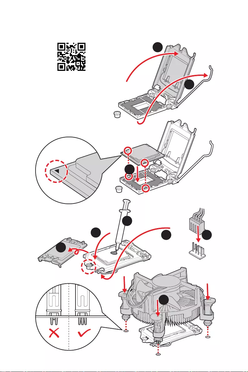
Installing a Processor/ Installation des Prozessors/ Installer un
processeur/ Установка процессора
⚽
1
2
3
6
45
7
8
9
III
Quick Start
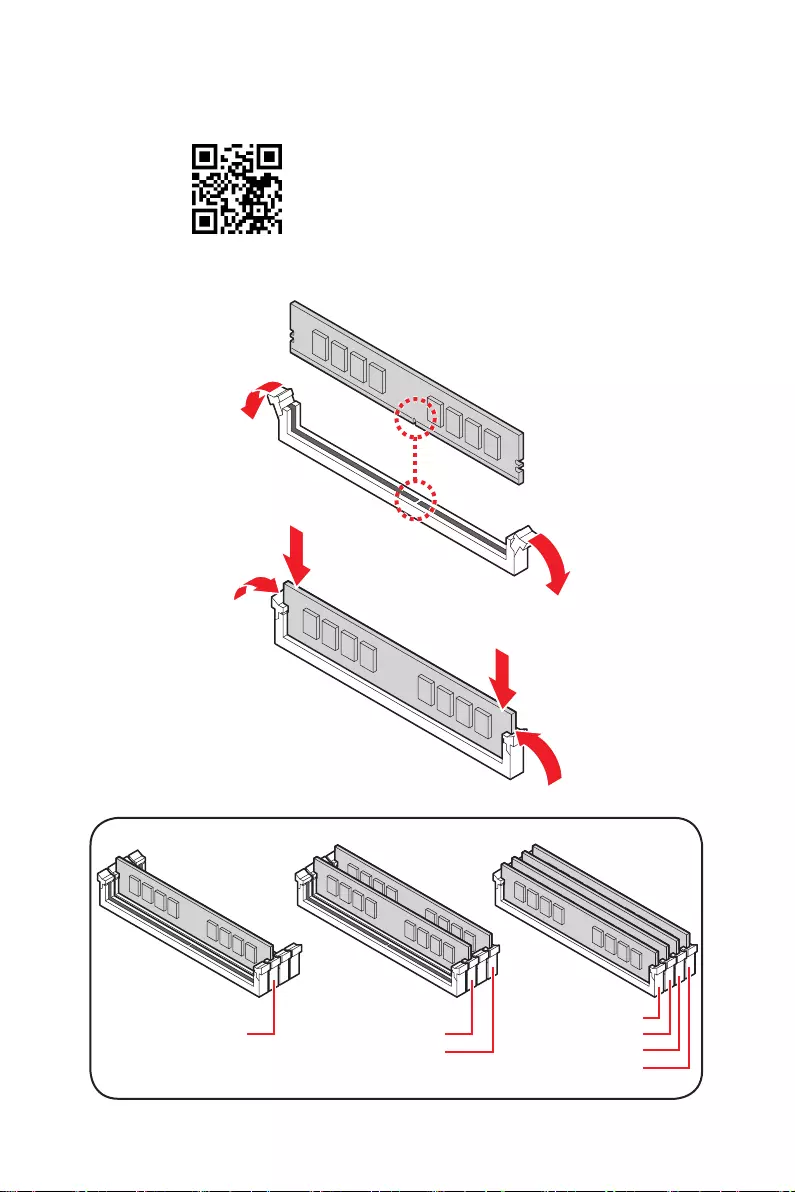
Installing DDR4 memory/ Installation des DDR4-Speichers/
Installer une mémoire DDR4/ Установка памяти DDR4
⚽
DIMMA2 DIMMA2
DIMMB2
DIMMA1
DIMMA2
DIMMB1
DIMMB2
IV Quick Start
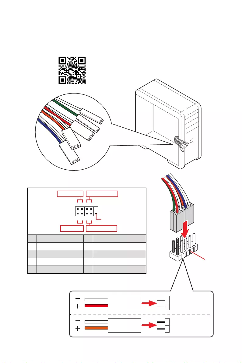
Connecting the Front Panel Header/ Anschließen der
Frontpanel—Stiftleiste/ Connecter un connecteur du panneau
avant/ Подключение разъемов передней панели
HDD LED
RESET SW
JFP1
HDD LED
HDD LED +
POWER LED +
POWER LED
1
2 10
9
+
+
+
+
Power LED
HDD LED Reset Switch
Reserved
Power Switch
JFP1
1 HDD LED + 2 Power LED +
3 4
5 Reset Switch 6 Power Switch
7 Reset Switch 8 Power Switch
9 Reserved 10 No Pin
RESET SW
POWER SW
POWER LED+
POWER LED-
HDD LED
⚽
V
Quick Start
1
⚽
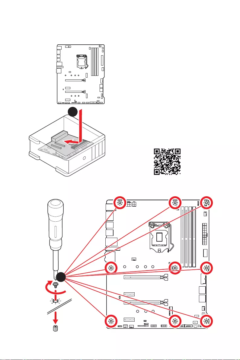
Installing the Motherboard/ Installation des Motherboards/
Installer la carte mère/ Установка материнской платы
3
Torque:
3 kgf·cm*
*3 kgf·cm
= 0.3 N·m
= 2.6 lbf·in
VI Quick Start
⚽
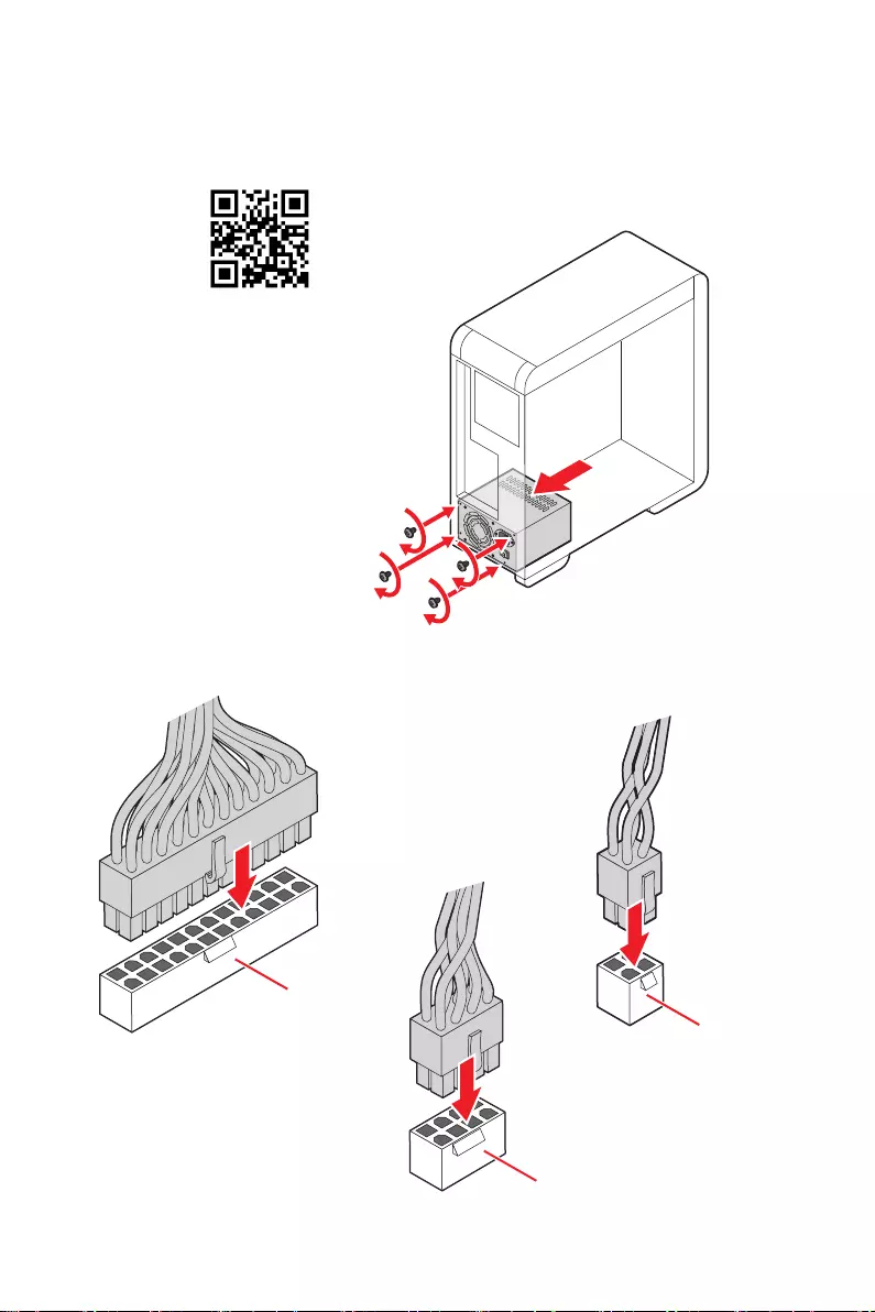
ATX_PWR1
CPU_PWR1
CPU_PWR2
Connecting the Power Connectors/ Stromanschlüsse
anschliessen/ Connecter les câbles du module d’alimentation/
Подключение разъемов питания
VII
Quick Start
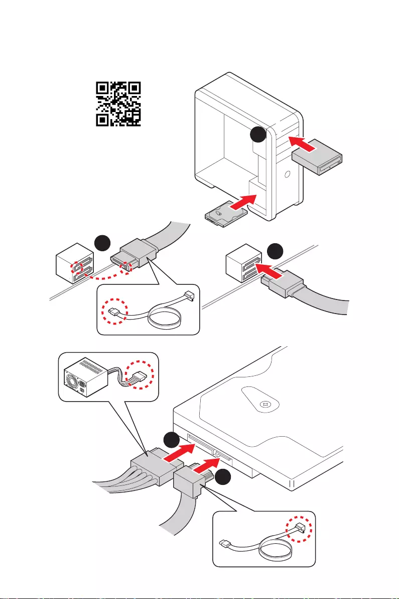
Installing SATA Drives/ Installation der SATA-Laufwerke/
Installer le disque dur SATA/ Установка дисков SATA
1
23
4
5
⚽
VIII Quick Start
1
2
3
4
5
6
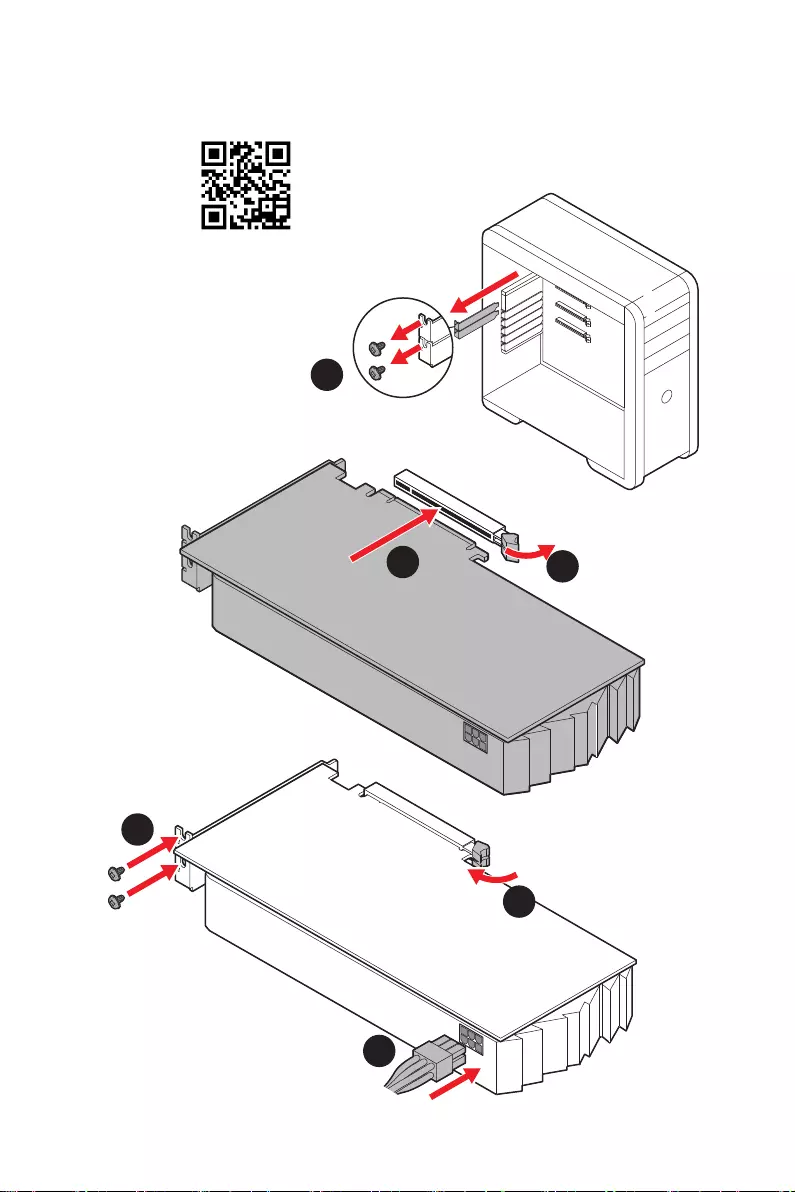
Installing a Graphics Card/ Einbau der Grafikkarte/ Installer
une carte graphique/ Установка дискретной видеокарты
⚽
IX
Quick Start
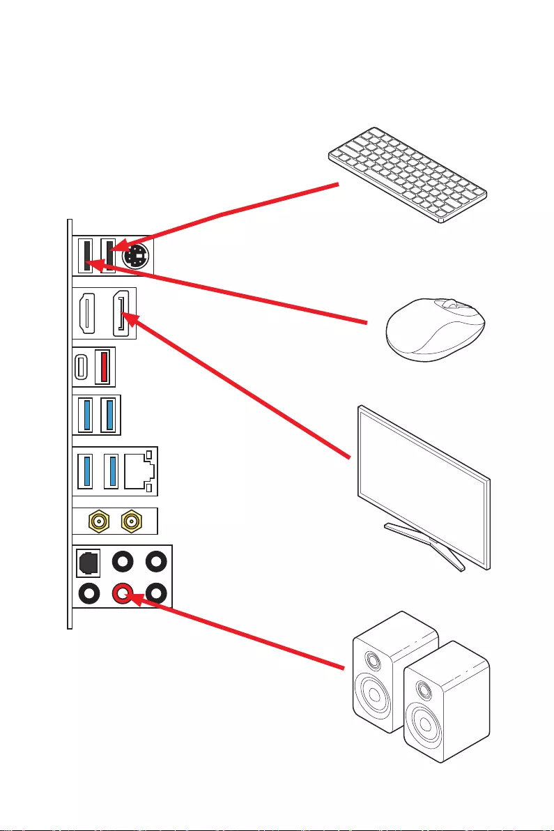
Connecting Peripheral Devices/ Peripheriegeräte/ Connecter
un périphérique anschliessen/ Подключение периферийных
устройств
XQuick Start
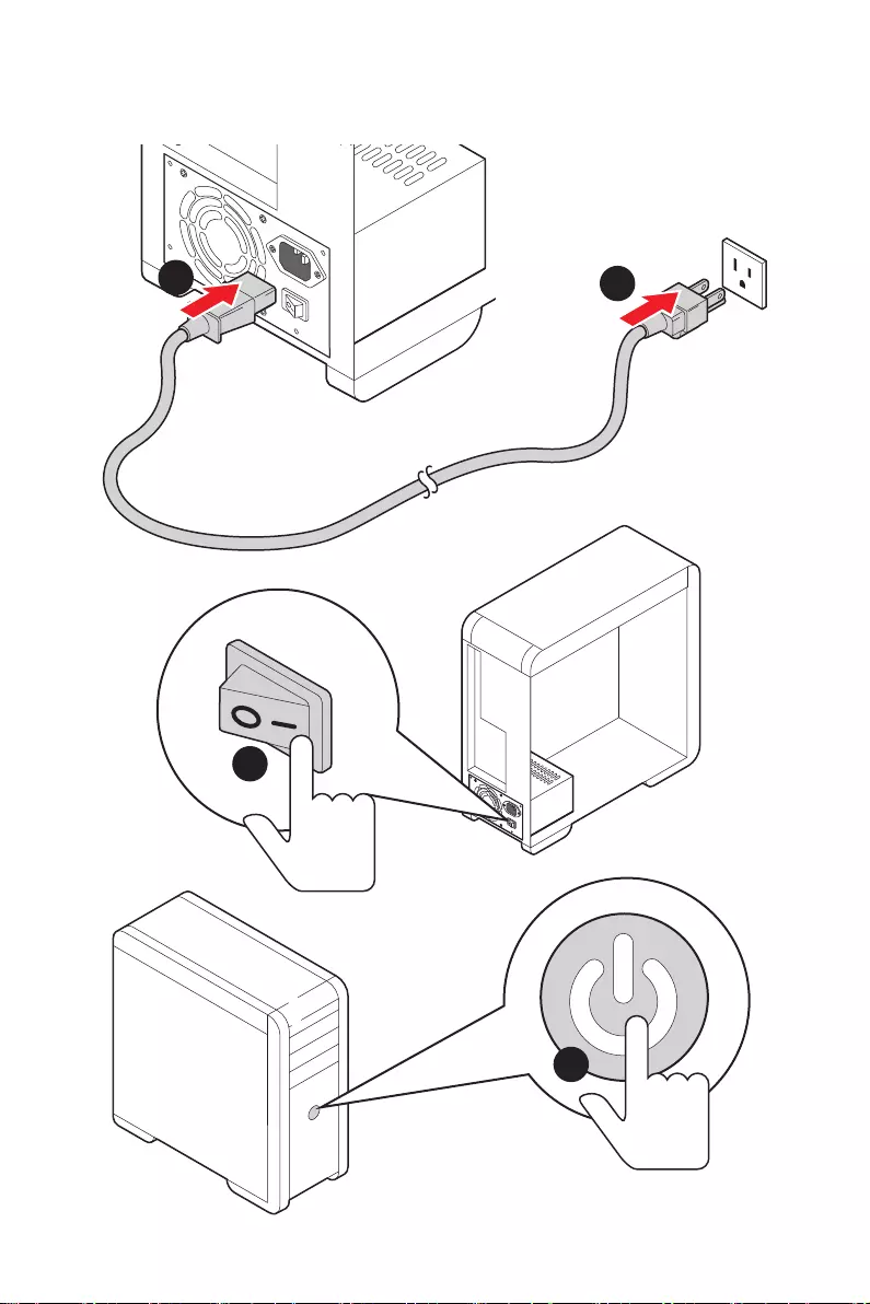
4
3
12
Power On/ Einschalten/ Mettre sous-tension/ Включение
питания

1
Contents
Contents
Safety Information ……………………………………………………………………………………. 3
Specifications …………………………………………………………………………………………… 4
Package contents …………………………………………………………………………………….. 9
Rear I/O Panel ……………………………………………………………………………………….. 10
LAN Port LED Status Table ………………………………………………………………………. 10
Audio Ports Configuration ………………………………………………………………………… 10
Realtek Audio Console …………………………………………………………………………….. 11
Overview of Components ………………………………………………………………………… 14
CPU Socket …………………………………………………………………………………………….. 15
DIMM Slots ……………………………………………………………………………………………… 16
PCI_E1~4: PCIe Expansion Slots ……………………………………………………………….. 17
CPU_PWR1, ATX_PWR1: Power Connectors ………………………………………………. 18
JFP1, JFP2: Front Panel Connectors …………………………………………………………. 19
JAUD1: Front Audio Connector …………………………………………………………………. 19
M2_1~2: M.2 Slots (Key M) ……………………………………………………………………….. 20
SATA1~6: SATA 6Gb/s Connectors …………………………………………………………….. 22
CPU_FAN1, PUMP_FAN1, SYS_FAN1~6: Fan Connectors ……………………………. 23
JUSB1~2: USB 2.0 Connectors ………………………………………………………………….. 24
…………………………………………………… 24
JUSB3: USB 3.2 Gen 1 Connector ……………………………………………………………… 25
……………………………………………… 26
JRTD3: Intel RTD3 Connector …………………………………………………………………… 26
JBAT1: Clear CMOS (Reset BIOS) Jumper ………………………………………………….. 27
JTPM1: TPM Module Connector ………………………………………………………………… 27
JCI1: Chassis Intrusion Connector …………………………………………………………….. 28
JRGB1~2: RGB LED connectors ………………………………………………………………… 29
JRAINBOW1~2: Addressable RGB LED connectors …………………………………….. 30
Onboard LEDs ………………………………………………………………………………………… 31
EZ Debug LED …………………………………………………………………………………………. 31
LED_SW1: EZ LED Control ……………………………………………………………………….. 31
Installing OS, Drivers & Utilities ………………………………………………………………. 32
Installing Windows® 10 …………………………………………………………………………….. 32
Installing Drivers …………………………………………………………………………………….. 32
Installing Utilities ……………………………………………………………………………………. 32
UEFI BIOS ………………………………………………………………………………………………. 33
BIOS Setup ……………………………………………………………………………………………… 34
Entering BIOS Setup ………………………………………………………………………………… 34

2Contents
Resetting BIOS ………………………………………………………………………………………… 35
Updating BIOS …………………………………………………………………………………………. 35
EZ Mode …………………………………………………………………………………………………. 37
Advanced Mode ………………………………………………………………………………………. 41
OC Menu…………………………………………………………………………………………………. 42

3
Safety Information
Safety Information
∙The components included in this package are prone to damage from electrostatic
discharge (ESD). Please adhere to the following instructions to ensure successful
computer assembly.
∙Ensure that all components are securely connected. Loose connections may cause
the computer to not recognize a component or fail to start.
∙Hold the motherboard by the edges to avoid touching sensitive components.
∙It is recommended to wear an electrostatic discharge (ESD) wrist strap when
handling the motherboard to prevent electrostatic damage. If an ESD wrist strap is
not available, discharge yourself of static electricity by touching another metal object
before handling the motherboard.
∙
pad whenever the motherboard is not installed.
∙Before turning on the computer, ensure that there are no loose screws or metal
components on the motherboard or anywhere within the computer case.
∙Do not boot the computer before installation is completed. This could cause
permanent damage to the components as well as injury to the user.
∙If you need help during any installation step, please consult a certified computer
technician.
∙Always turn off the power supply and unplug the power cord from the power outlet
before installing or removing any computer component.
∙Keep this user guide for future reference.
∙Keep this motherboard away from humidity.
∙Make sure that your electrical outlet provides the same voltage as is indicated on
the PSU, before connecting the PSU to the electrical outlet.
∙Place the power cord such a way that people can not step on it. Do not place
anything over the power cord.
∙All cautions and warnings on the motherboard should be noted.
∙If any of the following situations arises, get the motherboard checked by service
personnel:
▪Liquid has penetrated into the computer.
▪The motherboard has been exposed to moisture.
▪The motherboard does not work well or you can not get it work according to user
guide.
▪The motherboard has been dropped and damaged.
▪The motherboard has obvious sign of breakage.
∙Do not leave this motherboard in an environment above 60°C (140°F), it may damage
the motherboard.

4Specifications
Specifications
CPU
Supports 10th Gen Intel® Core™ and Pentium® Gold /
Celeron® processors for LGA 1200 socket*
* Please go to intel.com for compatibility information.
* Onboard graphics output are disabled when using the F SKU processors.
Chipset Intel® Z490 Chipset
Memory
∙4x DDR4 memory slots, support up to 128GB*
∙Supports 1R 2133/2666/2933 MHz*
▪1DPC 1R Max speed up to 4800+ MHz
▪1DPC 2R Max speed up to 4266+ MHz
▪2DPC 1R Max speed up to 4400+ MHz
▪2DPC 2R Max speed up to 4000+ MHz
∙
∙
∙Supports Intel® Extreme Memory Profile (XMP)
*Please refer www.msi.com for more information on compatible memory
Expansion Slot
∙1x PCIe 3.0 x16 slot (from CPU)
∙1x PCIe 3.0 x16 slot (x4 mode, from PCH)
∙2x PCIe x1 slots (from PCH)
* Please refer to page 29 for PCIe 3.0 bandwidth table.
Onboard Graphics
∙1x HDMI port, supports a maximum resolution of
4096×2160 @ 30Hz
∙1x DisplayPort port supports a maximum resolution of
4096 x 2304 @ 60Hz
Multi-GPU ∙
Storage
Intel® Z490 Chipset
∙6x SATA 6Gb/s ports*
∙2x M.2 slots (Key M)
▪Supports up to PCIe 3.0 x4 and SATA 6Gb/s
▪M2_1 slot supports 2242/ 2260 /2280/ 22110 storage
devices*
▪M2_2 slot supports 2242/ 2260 /2280 storage devices**
▪Intel® Optane™ Memory Ready***
* SATA2 will be unavailable when installing M.2 SATA SSD in the M2_1 slot.
** SATA5 & SATA6 will be unavailable when installing M.2 SATA/PCIe SSD in the
M2_2 slot.
*** Before using Intel® Optane™ memory modules, please ensure that you have
updated the drivers and BIOS to the latest version from MSI website.
Continued on next page

5
Specifications
Continued from previous page
RAID
Intel® Z490 Chipset
∙Supports RAID 0, RAID1, RAID 5 and RAID 10 for SATA
storage devices
∙Supports RAID 0 and RAID 1 for M.2 PCIe storage devices
LAN
USB
∙Intel® Z490 Chipset
▪
panel
▪
panel, 2 ports through the internal USB connector, 1
)
▪2x USB 2.0 ports on the back panel
▪4x USB 2.0 ports available through the internal USB
∙ASMedia® ASM3241
▪
panel
Audio
∙
∙Supports S/PDIF output
Wireless/ Bluetooth
Intel® AX201
∙
∙802.11ac; WiFi 6 pre certified
∙Bluetooth 5.1, FIPS, FISMA
∙
Back Panel
Connectors
∙1x PS/2 keyboard/ mouse combo port
∙2x USB 2.0 ports
∙1x Display port
∙1x HDMI port
∙
∙
∙1x LAN (RJ45) port
∙
∙
∙1x Optical S/PDIF OUT connector
∙5x audio jacks
Continued on next page

6Specifications
Continued from previous page
Internal Connectors
∙
∙
∙
∙6x SATA 6Gb/s connectors
∙
∙1x USB 3.2 Gen 1 5Gbps connector (support additional 2
USB 3.2 Gen 1 5Gbps ports)
∙2x USB 2.0 connectors (support additional 4 USB 2.0 ports)
∙
∙
∙
∙1x front panel audio connector
∙2x system panel connectors
∙1x chassis intrusion connector
∙1x Clear CMOS jumper
∙
∙
∙1x TPM module connector
∙1x TBT connector*
∙1x RTD3 connector
*Thunderbolt card need support RTD3
LED Features ∙1x LED Control switch
∙4x EZ Debug LED
I/O Controller NUVOTON NCT6687 Controller Chip
Hardware Monitor
∙CPU/System temperature detection
∙CPU/System fan speed detection
∙CPU/System fan speed control
Form Factor ∙ATX Form Factor
∙12 in. x 9.6 in. (30.5 cm x 24.4 cm)
BIOS Features
∙1x 256 Mb flash
∙UEFI AMI BIOS
∙ACPI 6.2, SM BIOS 3.2
∙
Continued on next page
7
Specifications
Continued from previous page
Software
∙Drivers
∙DRAGON CENTER
∙Intel Extreme Tuning Utility
∙MSI App Player (BlueStacks)
∙Open Broadcaster Software (OBS)
∙
∙Google Chrome™, Google Toolbar, Google Drive
∙Norton™ Internet Security Solution
Dragon Center
Features
∙Gaming Mode
∙Gaming Hotkey
∙LAN Manager
∙Mystic Light
∙Ambient Link
∙User Scenario
∙Monitor(Hardware
Monitor)
∙True Color
∙Live Update
∙DPC Latency tuner
∙Speed Up
∙Smart Tool
∙Super Charger
Please refer to http://download.msi.
com/manual/mb/DRAGONCENTER2.
pdf for more details.
Special Features
∙Audio
▪Audio Boost
∙Network
▪2.5G LAN
▪LAN Manager
▪Intel WiFi
∙Cooling
▪Extended Heatsink Design
▪M.2 Shield Frozr
▪Pump Fan
▪Smart Fan Control
Continued on next page

8Specifications
Continued from previous page
∙LED
▪Mystic Light
▪Mystic Light Extension (RGB)
▪Mystic Light Extension (RAINBOW)
▪Mystic Light Sync
▪EZ DEBUG LED
▪EZ LED Control
∙Protection
▪PCIe Steel Armor
▪
∙Performance
▪
▪DDR4 Boost
▪Core Boost
▪GAME Boost
▪Lightning USB 20G
▪USB 3.2 Gen 2 10G
▪USB with type A+C
▪
▪Dual CPU Power
∙Experience
▪DRAGON CENTER
▪Click BIOS 5

9
Package contents
Package contents
Please check the contents of your motherboard package. It should contain:
Motherboard MPG Z490 GAMING EDGE WIFI
Documentation
User manual 1
1
Quick installation guide 1
Application Driver DVD 1
Cables SATA 6G cables (2 cables/pack) 1
Accessories
1
Case badge 1
SATA cable stickers 1
Product registration card 1
M.2 screws (3 pcs./pack) 1
⚠
Important
If any of the above items are damaged or missing, please contact your retailer.
10 Rear I/O Panel
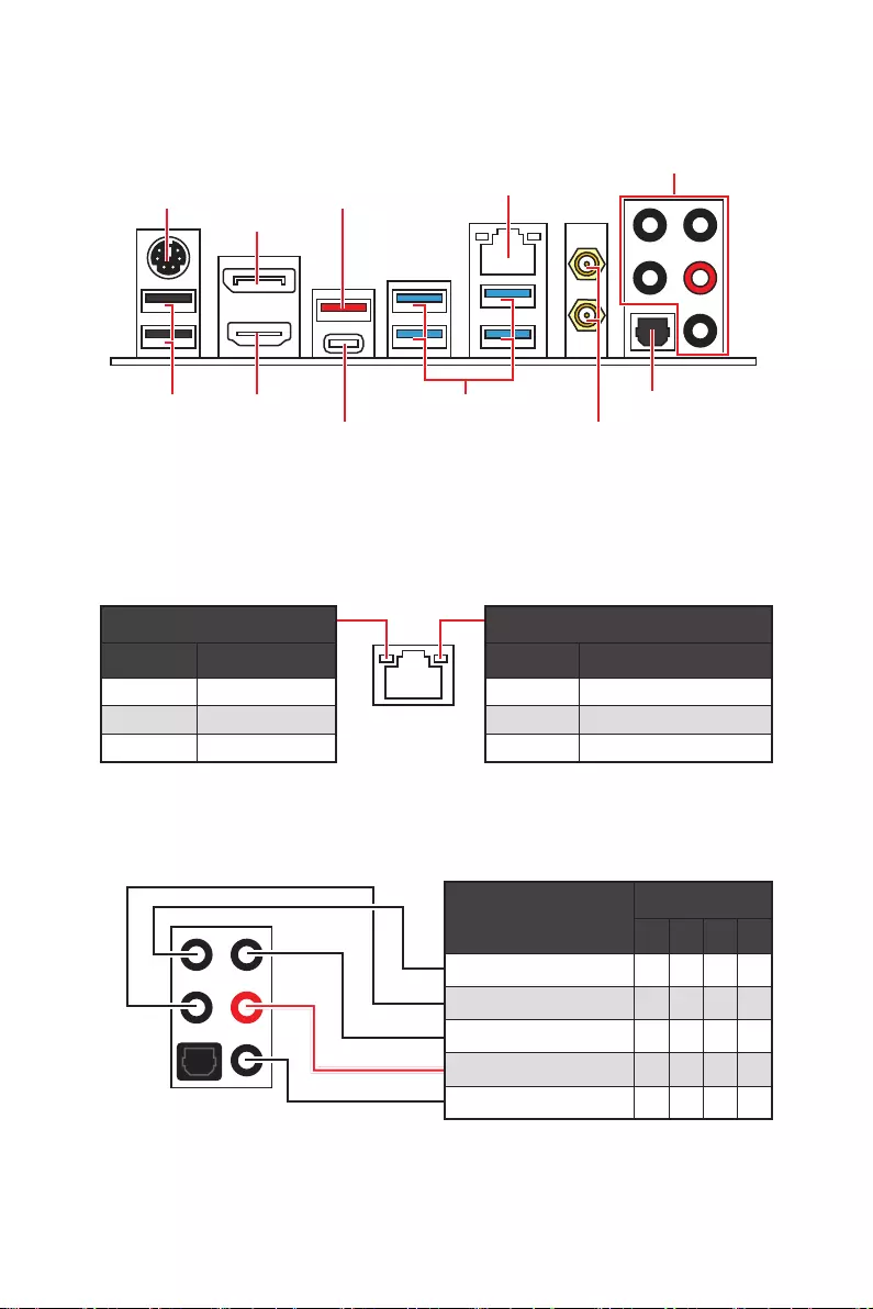
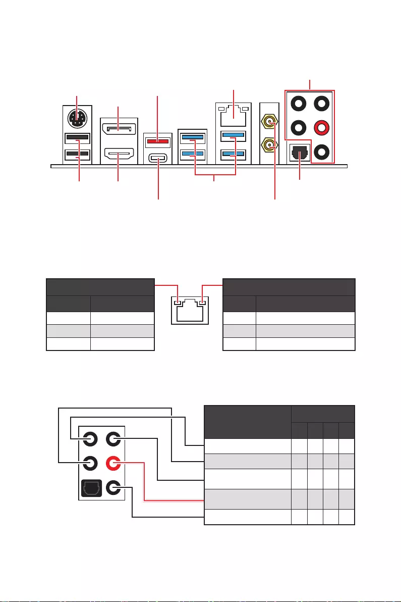
Rear I/O Panel
Audio Ports
WiFi antenna
connector
PS/2
HDMI port
Displayport
USB 2.0
2.5Gbps LAN
USB 3.2 Gen 2 10Gbps
USB 3.2 Gen 1 5Gbps
USB 3.2 Gen 2×2 20Gbps
Audio Ports Configuration
Audio Ports Channel
2468
Rear Speaker Out
Mic In
Blank: empty)
Link/ Activity LED
Status Description
Off No link
Yellow Linked
Blinking Data activity
Speed LED
Status Description
Off 10 Mbps connection
Green 100 Mbps / 1 Gbps connection
Orange 2.5 Gbps connection
LAN Port LED Status Table
11
Rear I/O Panel
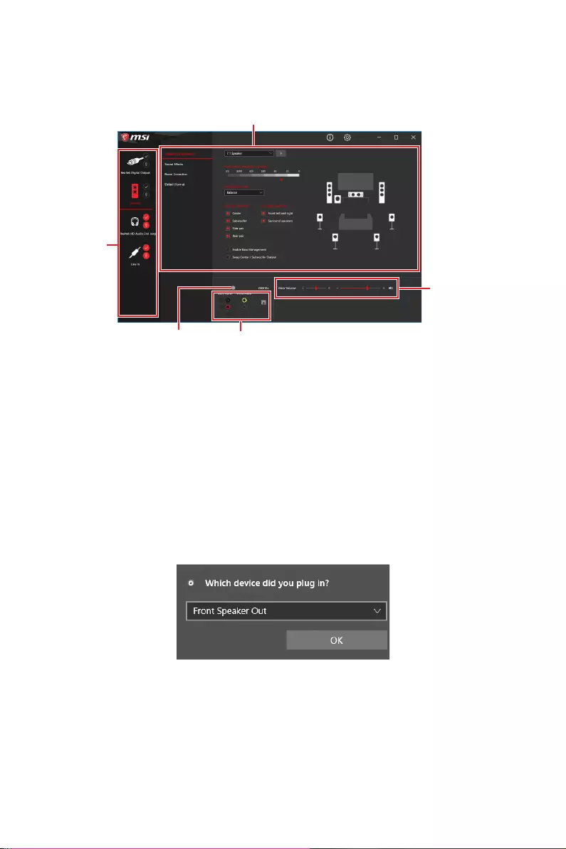
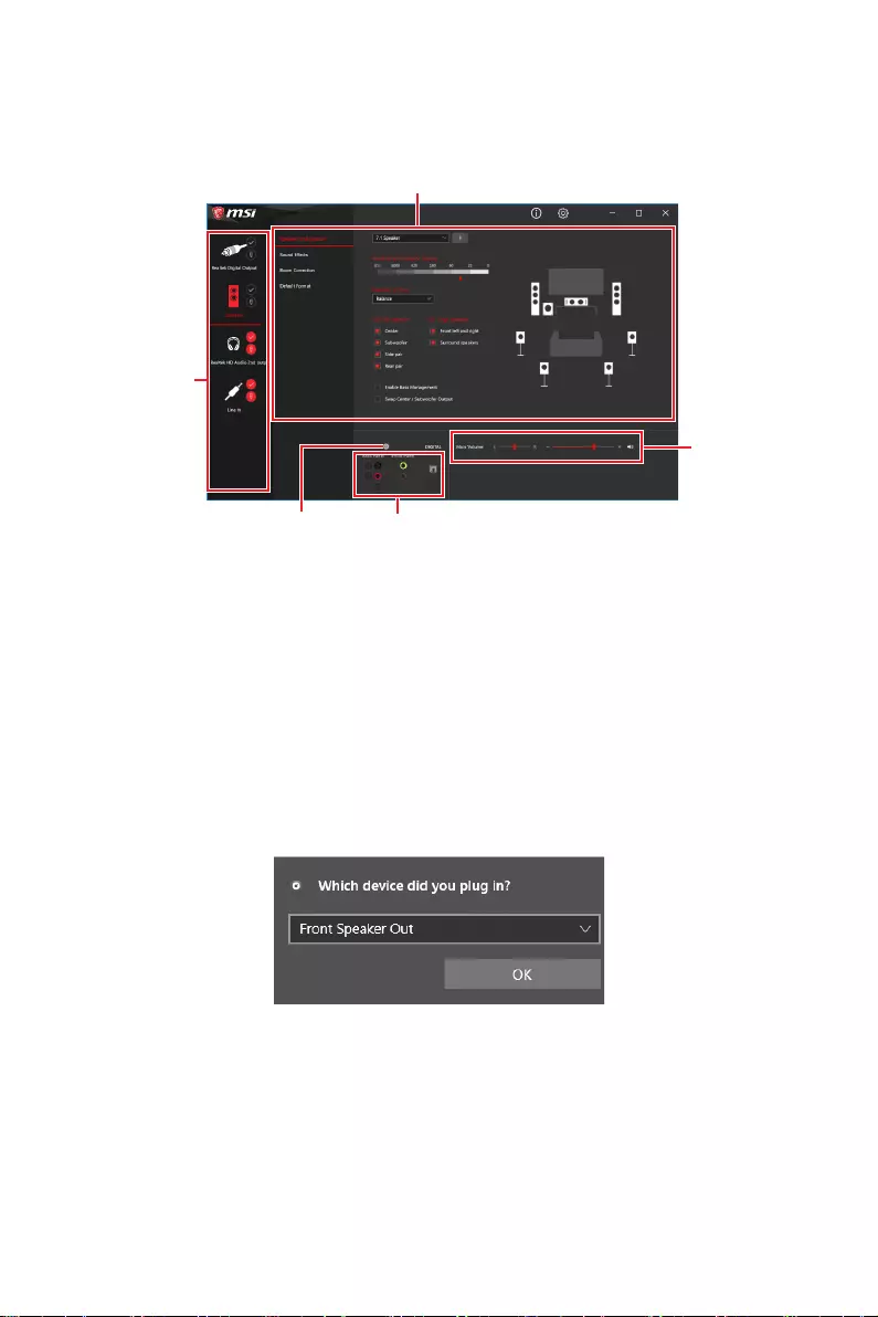
Realtek Audio Console
After Realtek Audio Console is installed. You can use it to change sound settings to get
better sound experience.
∙Device Selection
options. The check sign indicates the devices as default.
∙Application Enhancement
guidance of anticipated sound effect for both output and input device.
∙Main Volume
that you plugged in front or rear panel by adjust the bar.
∙Jack Status
computer.
∙Connector Settings
Auto popup dialog
When you plug into a device at an audio jack, a dialogue window will pop up asking you
which device is current connected.
Each jack corresponds to its default setting as shown on the next page.
⚠
Important
The pictures above for reference only and may vary from the product you purchased.
Jack Status
Connector Settings
Device
Selection
Main Volume
Application Enhancement
12 Rear I/O Panel
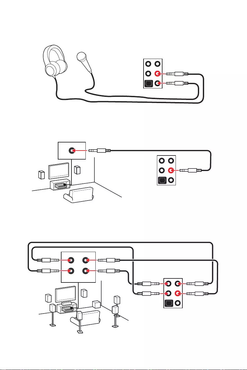
Audio jacks to headphone and microphone diagram
Audio jacks to stereo speakers diagram
Audio jacks to 7.1-channel speakers diagram
AUDIO INPUT
AUDIO INPUT
Rear Front
Side Center/
Subwoofer

13
Rear I/O Panel
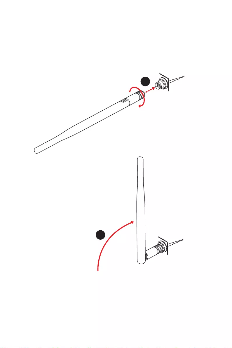
Installing antennas
1. Screw the antennas tight to the antenna connectors as shown below.
2. Orient the antennas.
1
2
14 Overview of Components
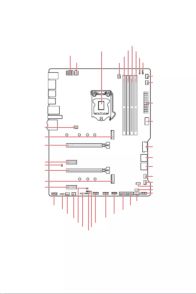
Overview of Components
DIMMA1
CPU_FAN1
DIMMA2
DIMMB1
DIMMB2
JRGB2
JRAINBOW2
PUMP_FAN1
SYS_FAN6
SYS_FAN5
SYS_FAN1
SYS_FAN4
LED_SW1
JRTD3
JFP1
JTBT1
SATA6
SATA5
JTPM1
JUSB1
JUSB2
JFP2
JT1
JBAT1
JRAINBOW1
ATX_PWR1
JUSB4
JUSB3
CPU Socket
CPU_PWR1
CPU_PWR2
SYS_FAN3
SYS_FAN2
JRGB1
JAUD1
PCI_E4
PCI_E3
M2_2
M2_1
JCI1
PCI_E2
PCI_E1
15
Overview of Components
⚠
Important
∙
Always unplug the power cord from the power outlet before installing or removing
the CPU.
∙
Please retain the CPU protective cap after installing the processor. MSI will deal
with Return Merchandise Authorization (RMA) requests if only the motherboard comes
with the protective cap on the CPU socket.
∙
When installing a CPU, always remember to install a CPU heatsink. A CPU heatsink
is necessary to prevent overheating and maintain system stability.
∙
Confirm that the CPU heatsink has formed a tight seal with the CPU before booting
your system.
∙
Overheating can seriously damage the CPU and motherboard. Always make sure
the cooling fans work properly to protect the CPU from overheating. Be sure to apply
an even layer of thermal paste (or thermal tape) between the CPU and the heatsink to
enhance heat dissipation.
∙
Whenever the CPU is not installed, always protect the CPU socket pins by covering
the socket with the plastic cap.
∙
If you purchased a separate CPU and heatsink/ cooler, Please refer to the
documentation in the heatsink/ cooler package for more details about installation.
∙
This motherboard is designed to support overclocking. Before attempting to
overclock, please make sure that all other system components can tolerate
overclocking. Any attempt to operate beyond product specifications is not
recommended. MSI® does not guarantee the damages or risks caused by inadequate
operation beyond product specifications.
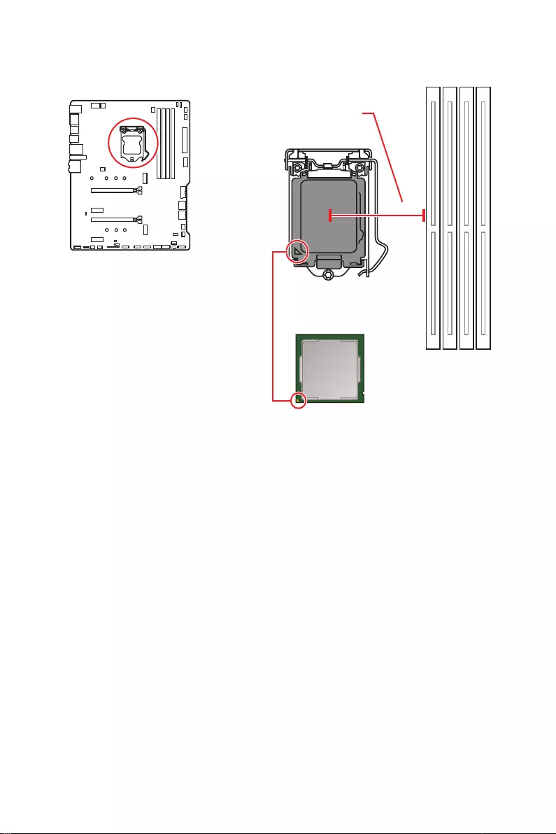
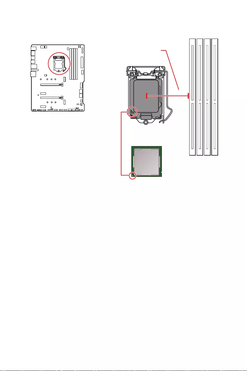
CPU Socket
Introduction to the LGA 1200 CPU
The surface of the LGA 1200 CPU has
two notches and a golden triangle to
assist in correctly lining up the CPU for
motherboard placement. The golden
triangle is the Pin 1 indicator.
50.6 mm
Distance from the center of the
CPU to the nearest DIMM slot.
16 Overview of Components
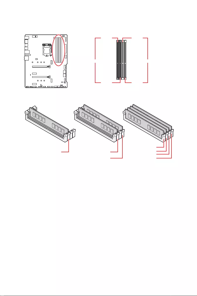
DIMM Slots
DIMMA1 DIMMB1
Channel A Channel B
DIMMA2 DIMMB2
Memory module installation recommendation
⚠
Important
∙
Always insert memory modules in the DIMMA2 slot first.
∙
To ensure system stability for Dual channel mode, memory modules must be of the
same type, number and density.
∙
Some memory modules may operate at a lower frequency than the marked value
when overclocking due to the memory frequency operates dependent on its Serial
Presence Detect (SPD). Go to BIOS and find the DRAM Frequency to set the memory
frequency if you want to operate the memory at the marked or at a higher frequency.
∙
It is recommended to use a more efficient memory cooling system for full DIMMs
installation or overclocking.
∙
The stability and compatibility of installed memory module depend on installed CPU
and devices when overclocking.
∙
Please refer www.msi.com for more information on compatible memory.
DIMMB2 DIMMB2
DIMMB1
DIMMA2 DIMMA2 DIMMA2
DIMMA1

17
Overview of Components
PCI_E1~4: PCIe Expansion Slots
⚠
Important
∙
If you install a large and heavy graphics card, you need to use a tool such as MSI
Gaming Series Graphics Card Bolster to support its weight to prevent deformation of
the slot.
∙
For a single PCIe x16 expansion card installation with optimum performance, using
the PCI_E1 slot is recommended.
∙
When adding or removing expansion cards, always turn off the power supply and
unplug the power supply power cable from the power outlet. Read the expansion
card’s documentation to check for any necessary additional hardware or software
changes.
PCI_E1: PCIe 3.0 x16 (CPU)
PCI_E3: PCIe 3.0 x4 (PCH)
PCI_E2: PCIe 3.0 x1 (PCH)
PCI_E4: PCIe 3.0 x1 (PCH)
18 Overview of Components
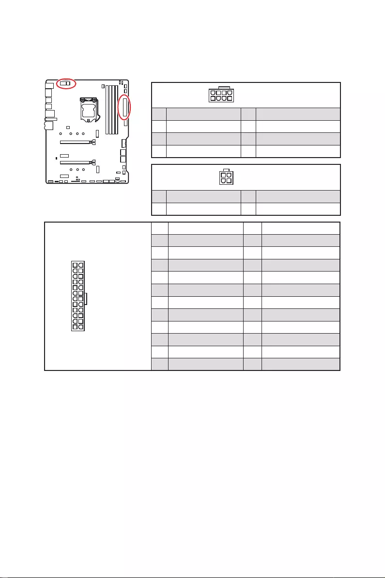
24
131
12
ATX_PWR1
1 +3.3V 13 +3.3V
2 +3.3V 14
3 Ground 15 Ground
4 +5V 16
5 Ground 17 Ground
6 +5V 18 Ground
7 Ground 19 Ground
8 PWR OK 20 Res
9 5VSB 21 +5V
10 +12V 22 +5V
11 +12V 23 +5V
12 +3.3V 24 Ground
5
4 1
8CPU_PWR1
1 Ground 5 +12V
2 Ground 6 +12V
3 Ground 7 +12V
4 Ground 8 +12V
⚠
Important
Make sure that all the power cables are securely connected to a proper ATX power
supply to ensure stable operation of the motherboard.
CPU_PWR1, ATX_PWR1: Power Connectors
These connectors allow you to connect an ATX power supply.
3
2 1
4CPU_PWR2
1 Ground 3 +12V
2 Ground 4 +12V

19
Overview of Components
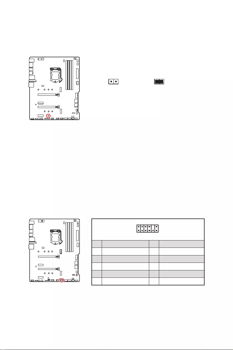
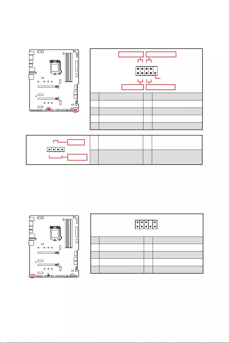
JFP1, JFP2: Front Panel Connectors
These connectors connect to the switches and LEDs on the front panel.
1
2 10
9
+
+
+
+
Power LED
HDD LED Reset Switch
Reserved
Power Switch
JFP1
1 HDD LED + 2 Power LED +
3 4
5 Reset Switch 6 Power Switch
7 Reset Switch 8 Power Switch
9 Reserved 10 No Pin
1
JFP2
+
+
Speaker
Buzzer 1 2 Buzzer +
3 4 Speaker +
JAUD1: Front Audio Connector
This connector allows you to connect audio jacks on the front panel.
1
2 10
9
1 MIC L 2 Ground
3 MIC R 4 NC
5 Head Phone R 6 MIC Detection
7 SENSE_SEND 8 No Pin
9 Head Phone L 10 Head Phone Detection

20 Overview of Components
M2_1~2: M.2 Slots (Key M)
⚠
Important
∙
Intel® RST only supports PCIe M.2 SSD with UEFI ROM.
∙
Intel® Optane™ Memory Ready for all M.2 slots.
⚽
Video Demonstration
Watch the video to learn how to Install
M.2 module.
1
1
2
Installing M.2 module
1. Loosen the screws of M.2 SHIELD FROZR heatsink.
2. Remove the M.2 SHIELD FROZR and remove the protective films from the thermal
pads.

21
Overview of Components
30º30º
5
4
3
8.5H screw
Standoff
3. Move the position of the standoffs according to your M.2 SSDs length if need.
4.
5. Secure the M.2 SSD in place with the supplied M.2 8.5H screw.
6. Put the M.2 SHIELD FROZR heatsink back in place and secure it.
6
6

22 Overview of Components
SATA1~6: SATA 6Gb/s Connectors
These connectors are SATA 6Gb/s interface ports. Each connector can connect to one
SATA device.
⚠
Important
∙
transmission otherwise.
∙
SATA cables have identical plugs on either sides of the cable. However, it is
recommended that the flat connector be connected to the motherboard for space
saving purposes.
∙
SATA2 will be unavailable when installing M.2 SATA SSD in the M2_1 slot.
∙
SATA5 & SATA6 will be unavailable when installing M.2 SSD in the M2_2 slot.
SATA1
SATA3
SATA2
SATA4
SATA5
SATA6
M.2 & SATA combination table
Slot Available SATA connectors
M2_1 PCIe SATA PCIe SATA PCIe SATA
M2_2 PCIe PCIe SATA SATA
SATA1
SATA2
SATA3
SATA4
SATA5
SATA6
(SATA: M.2 SATA SSD, PCIe
23
Overview of Components
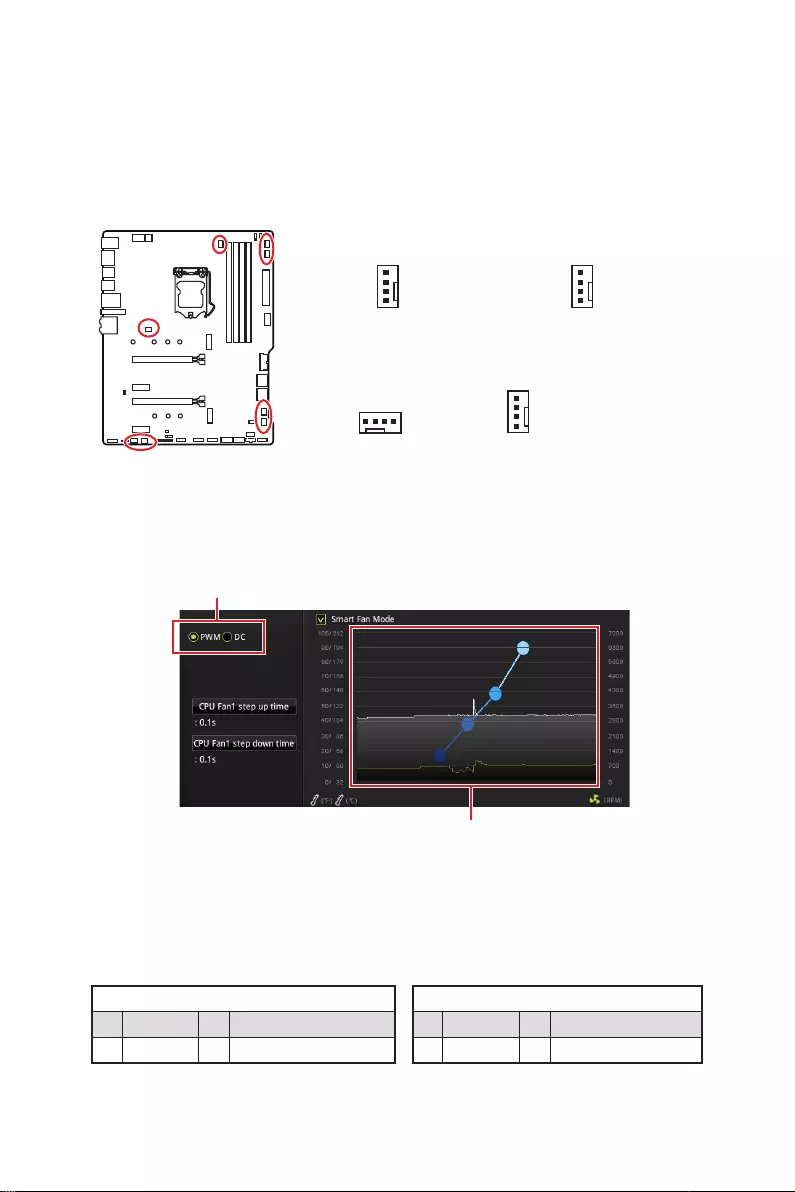
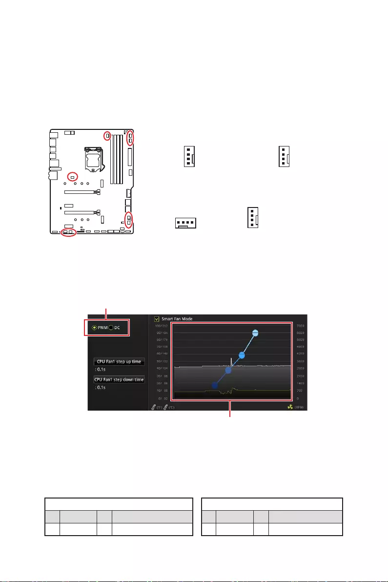
CPU_FAN1, PUMP_FAN1, SYS_FAN1~6: Fan Connectors
Fan connectors can be classified as PWM (Pulse Width Modulation) Mode or DC Mode.
PWM Mode fan connectors provide constant 12V output and adjust fan speed with
speed control signal. DC Mode fan connectors control fan speed by changing voltage.
You can follow the instruction below to adjust the fan connector to PWM or DC Mode.
Switching fan mode and adjusting fan speed
You can switch between PWM mode and DC mode and adjust fan speed in BIOS >
HARDWARE MONITOR.
Select PWM mode or DC mode
⚠
Important
Make sure fans are working properly after switching the PWM/ DC mode.
There are gradient points of the fan speed that allow you to adjust
fan speed in relation to CPU temperature.
PWM Mode pin definition
1 Ground 2 +12V
3 Sense 4 Speed Control Signal
DC Mode pin definition
1 Ground 2 Voltage Control
3 Sense 4 NC
Pin definition of fan connectors
Default DC Mode fan connectors
Default PWM Mode
fan connector
Default Auto Mode
fan connector
1
SYS_FAN4~6
1
SYS_FAN1~3
1
CPU_FAN1
1
PUMP_FAN1
24 Overview of Components
JUSB1~2: USB 2.0 Connectors
These connectors allow you to connect USB 2.0 ports on the front panel.
1
2 10
9
1 VCC 2 VCC
3 4
5 USB0+ 6 USB1+
7 Ground 8 Ground
9 No Pin 10 NC
⚠
Important
∙
Note that the VCC and Ground pins must be connected correctly to avoid possible
damage.
∙
In order to recharge your iPad,iPhone and iPod through USB ports, please install
MSI
DRAGON CENTER utility.
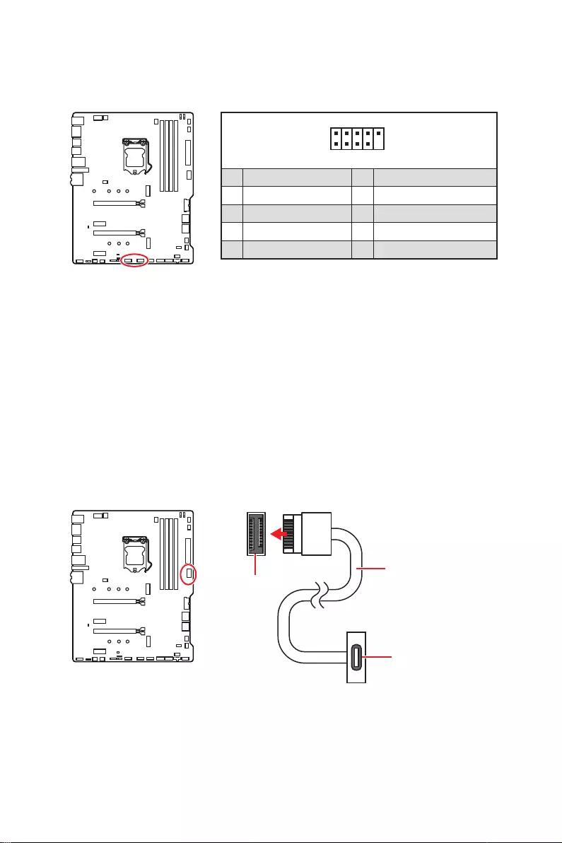
JUSB4: USB 3.2 Gen 1 Type-C Connector
panel. The connector possesses a foolproof design. When you connect the cable, be
sure to connect it with the corresponding orientation.
JUSB4
the front panel

25
Overview of Components
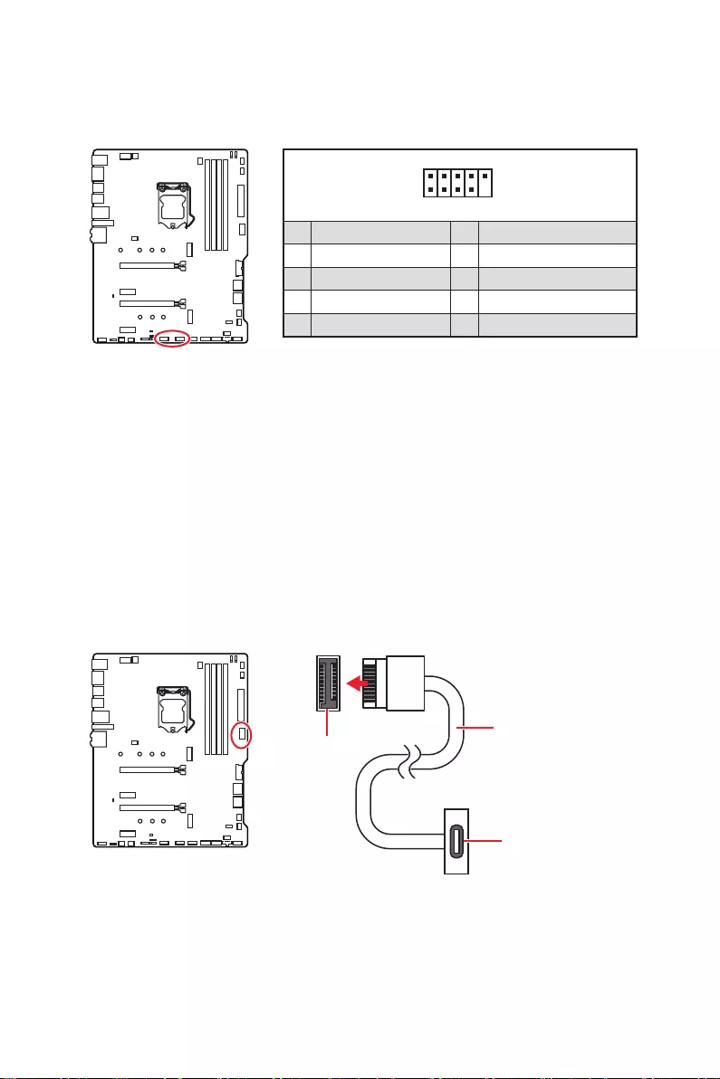
JUSB3: USB 3.2 Gen 1 Connector
These connectors allow you to connect USB 3.2 Gen 1 ports on the front panel.
1
10 11
20
1 Power 11 USB2.0+
2 USB3_RX_DN 12
3 USB3_RX_DP 13 Ground
4 Ground 14 USB3_TX_C_DP
5 USB3_TX_C_DN 15 USB3_TX_C_DN
6 USB3_TX_C_DP 16 Ground
7 Ground 17 USB3_RX_DP
8 18 USB3_RX_DN
9 USB2.0+ 19 Power
10 NC 20 No Pin
⚠
Important
Note that the Power and Ground pins must be connected correctly to avoid possible
damage.
26 Overview of Components
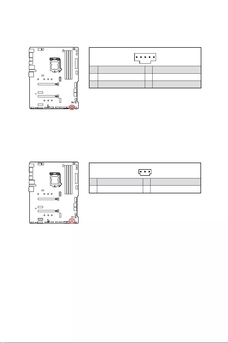
JTBT1: Thunderbolt Add-on Card Connector
1
1 FORCE_PWR 2 SCI_EVENT
3 4
5 GND
JRTD3: Intel RTD3 Connector
I/O card that supports RTD3.
1
1 WAKE 2 PWR EN
3 GND
27
Overview of Components
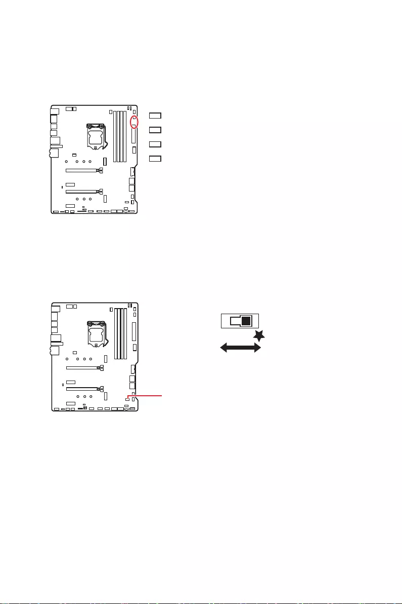
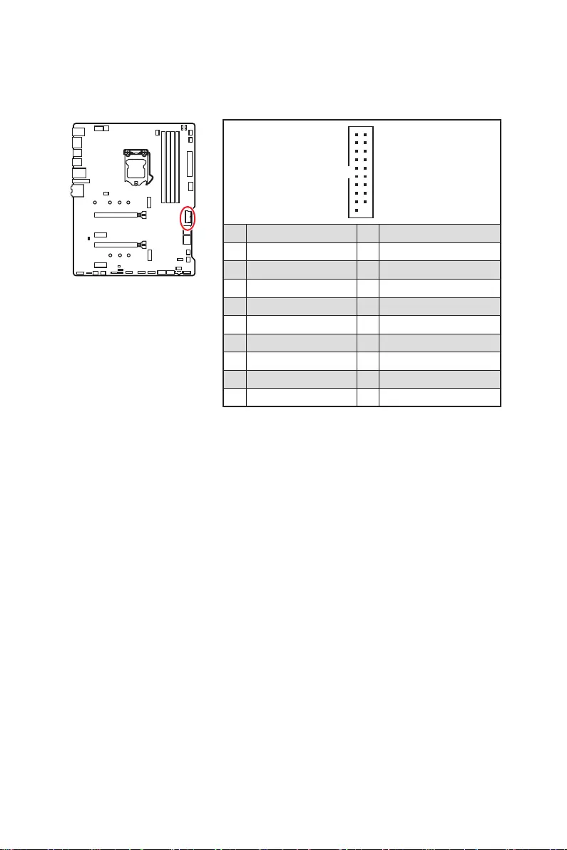
JBAT1: Clear CMOS (Reset BIOS) Jumper
There is CMOS memory onboard that is external powered from a battery located on
the motherboard to save system configuration data. If you want to clear the system
configuration, set the jumper to clear the CMOS memory.
Keep Data
(default) Clear CMOS/
Reset BIOS
Resetting BIOS to default values
1. Power off the computer and unplug the power cord
2.
3. Remove the jumper cap from JBAT1.
4. Plug the power cord and power on the computer.
1
2 12
11
1 SPI Power 2 SPI Chip Select
3
Master In Slave Out (SPI Data)
4
Master In Slave In (SPI Data)
5 Reserved 6 SPI Clock
7 Ground 8 SPI Reset
9 Reserved 10 No Pin
11 Reserved 12 Interrupt Request
JTPM1: TPM Module Connector
This connector is for TPM (Trusted Platform Module). Please refer to the TPM security
platform manual for more details and usages.

28 Overview of Components
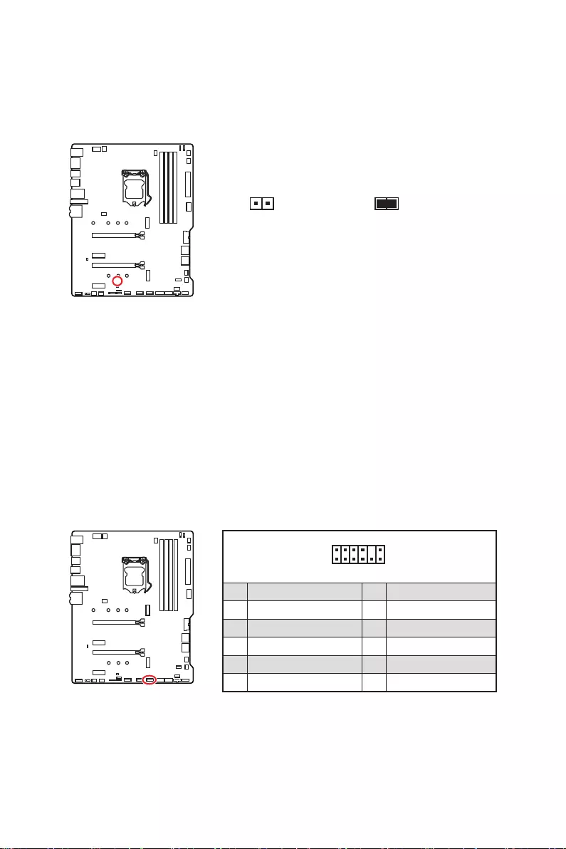
JCI1: Chassis Intrusion Connector
This connector allows you to connect the chassis intrusion switch cable.
Normal
(default)
Trigger the chassis
intrusion event
Using chassis intrusion detector
1. Connect the JCI1 connector to the chassis intrusion switch/ sensor on the chassis.
2. Close the chassis cover.
3. Go to BIOS > SETTINGS > Security > Chassis Intrusion Configuration.
4. Set Chassis Intrusion to Enabled.
5. Press F10 to save and exit and then press the Enter key to select Yes.
6. Once the chassis cover is opened again, a warning message will be displayed on
screen when the computer is turned on.
Resetting the chassis intrusion warning
1. Go to BIOS > SETTINGS > Security > Chassis Intrusion Configuration.
2. Set Chassis Intrusion to Reset.
3. Press F10 to save and exit and then press the Enter key to select Yes.
29
Overview of Components
⚠
Important
∙
The JRGB connector supports up to 2 meters continuous 5050 RGB LED strips
(12V/G/R/B) with the maximum power rating of 3A (12V).
∙
Always turn off the power supply and unplug the power cord from the power outlet
before installing or removing the RGB LED strip.
∙
Please use MSI’s software to control the extended LED strip.
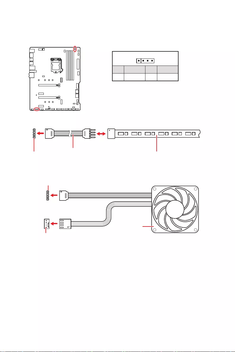
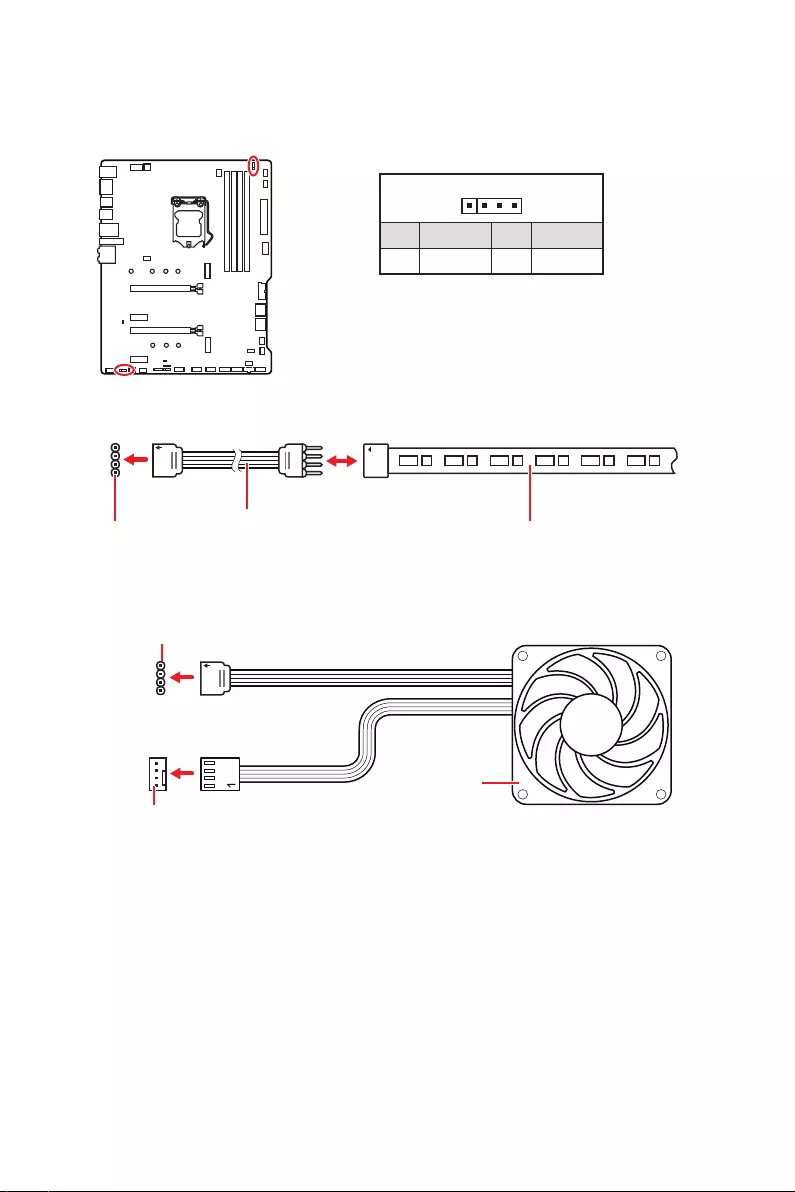
JRGB1~2: RGB LED connectors
The JRGB connector allows you to connect the 5050 RGB LED strips 12V.
1
GRB
JRGB
connector
RGB extension
cable 5050 RGB LED strips 12V
1
1 +12V 2 G
3 R 4 B
RGB LED Strip Connection
1
1
GRB
JRGB connector
System Fan connector
RGB LED Fan Connection
RGB LED Fan

30 Overview of Components
1
1
1
D
+5V
⚠
CAUTION
Do not connect the wrong type of LED strips. The JRGB connector and the JRAINBOW
connector provide different voltages, and connecting the 5V LED strip to the JRGB
connector will result in damage to the LED strip.
⚠
Important
∙
The JRAINBOW connector supports up to 75 LEDs WS2812B Individually
Addressable RGB LED strips (5V/Data/Ground) with the maximum power rating of 3A
(5V). In the case of 20% brightness, the connector supports up to 200 LEDs.
∙
Always turn off the power supply and unplug the power cord from the power outlet
before installing or removing the RGB LED strip.
∙
Please use MSI’s software to control the extended LED strip.
JRAINBOW1~2: Addressable RGB LED connectors
The JRAINBOW connectors allow you to connect the WS2812B Individually
Addressable RGB LED strips 5V.
JRAINBOW
connector
JRAINBOW connector
System Fan connector
Rainbow RGB LED
extension cable WS2812B Individually
Addressable RGB LED strips 5V
1
1 +5V 2 Data
3 No Pin 4 Ground
Addressable RGB LED Strip Connection
Addressable RGB LED Fan Connection
Addressable RGB LED Fan
31
Onboard LEDs
Onboard LEDs
EZ Debug LED
These LEDs indicate the debug status of the motherboard.
CPU
DRAM
VGA
BOOT
or fail.
LED_SW1: EZ LED Control
This switch is used to switch on/ off all the LEDs of motherboard.
LED_SW1
LED_OFF LED_ON
(Default)

32 Installing OS, Drivers & Utilities
Installing OS, Drivers & Utilities
Please download and update the latest utilities and drivers at www.msi.com
Installing Windows® 10
1. Power on the computer.
2. Insert the Windows® 10 installation disc/USB into your computer.
3. Press the Restart button on the computer case.
4. Press F11
Menu.
5. Select the Windows® 10 installation disc/USB from the Boot Menu.
6. Press any key when screen shows Press any key to boot from CD or DVD…
message.
7. Follow the instructions on the screen to install Windows® 10.
Installing Drivers
1. Start up your computer in Windows® 10.
2. Insert MSI® Driver Disc into your optical drive.
3. Click the Select to choose what happens with this disc
select Run DVDSetup.exe to open the installer. If you turn off the AutoPlay feature
from the Windows Control Panel, you can still manually execute the DVDSetup.exe
from the root path of the MSI Driver Disc.
4. The installer will find and list all necessary drivers in the Drivers/Software tab.
5. Click the Install
6. The drivers installation will then be in progress, after it has finished it will prompt
you to restart.
7. Click OK button to finish.
8. Restart your computer.
Installing Utilities
Before you install utilities, you must complete drivers installation.
1. Open the installer as described above.
2. Click the Utilities tab.
3. Select the utilities you want to install.
4. Click the Install
5. The utilities installation will then be in progress, after it has finished it will prompt
you to restart.
6. Click OK button to finish.
7. Restart your computer.

33
UEFI BIOS
UEFI BIOS
MSI UEFI BIOS is compatible with UEFI (Unified Extensible Firmware Interface)
architecture. The UEFI BIOS firmware infrastructure has many new functions and
advantages that traditional BIOS cannot achieve. It will fully support future PCs and
devices that comply with UEFI firmware architecture.
⚠
Important
The term BIOS in this user guide refers to UEFI BIOS unless otherwise noted.
UEFI advantages
∙
test process. And also eliminates the time to switch to CSM mode during POST
∙Supports for hard drive partitions larger than 2 TB.
∙Supports more than 4 primary partitions with a GUID Partition Table (GPT).
∙Supports unlimited number of partitions
∙
compatibility.
∙
ensure that no malware tampers with the startup process.
Incompatible UEFI cases
∙32-bit Windows operating system
10 operating system.
∙Older graphics card
warning message There is no GOP (Graphics Output protocol) support detected in
this graphics card.
⚠
Important
We recommend that you to replace with a GOP/UEFI compatible graphics card or
using integrated graphics from CPU for having normal function..
How to check the BIOS mode?
After entering the BIOS, find the BIOS Mode at the top of the screen.
CPU Temperature:
MotherBoard Temperature:
VCore:
DDR Voltage:
BIOS Mode: UEFI
UEFI boot mode

34 UEFI BIOS
BIOS Setup
The default settings offer the optimal performance for system stability in normal
conditions. You should always keep the default settings to avoid possible system
damage or failure booting unless you are familiar with BIOS.
⚠
Important
∙
BIOS items are continuously update for better system performance. Therefore, the
description may be slightly different from the latest BIOS and should be for reference
only. You could also refer to the HELP information panel for BIOS item description.
∙
The pictures in this chapter are for reference only and may vary from the product
you purchased.
∙
The BIOS items will vary with the processor.
Entering BIOS Setup
Press Delete key, when the Press DEL key to enter Setup Menu, F11 to enter Boot
Menu message appears on the screen during the boot process.
Function key
F1: General Help list
F2: Add/ Remove a favorite item
F3: Enter Favorites menu
F4: Enter CPU Specifications menu
F5
F6: Load optimized defaults
F7: Switch between Advanced mode and EZ mode
F8: Load Overclocking Profile
F9: Save Overclocking Profile
F10: Save Change and Reset*
F12: Take a screenshot and save it to USB flash drive (FAT/ FAT32 format only).
Ctrl+F: Enter Search page
* When you press F10, a confirmation window appears and it provides the modification
information. Select between Yes or No to confirm your choice.
35
UEFI BIOS
Resetting BIOS
You might need to restore the default BIOS setting to solve certain problems. There
are several ways to reset BIOS:
∙Go to BIOS and press F6 to load optimized defaults.
∙Short the Clear CMOS jumper on the motherboard.
⚠
Important
Be sure the computer is off before clearing CMOS data. Please refer to the Clear
CMOS jumper section for resetting BIOS.
Updating BIOS
Updating BIOS with M-FLASH
Before updating:
Please download the latest BIOS file that matches your motherboard model from MSI
website. And then save the BIOS file into the USB flash drive.
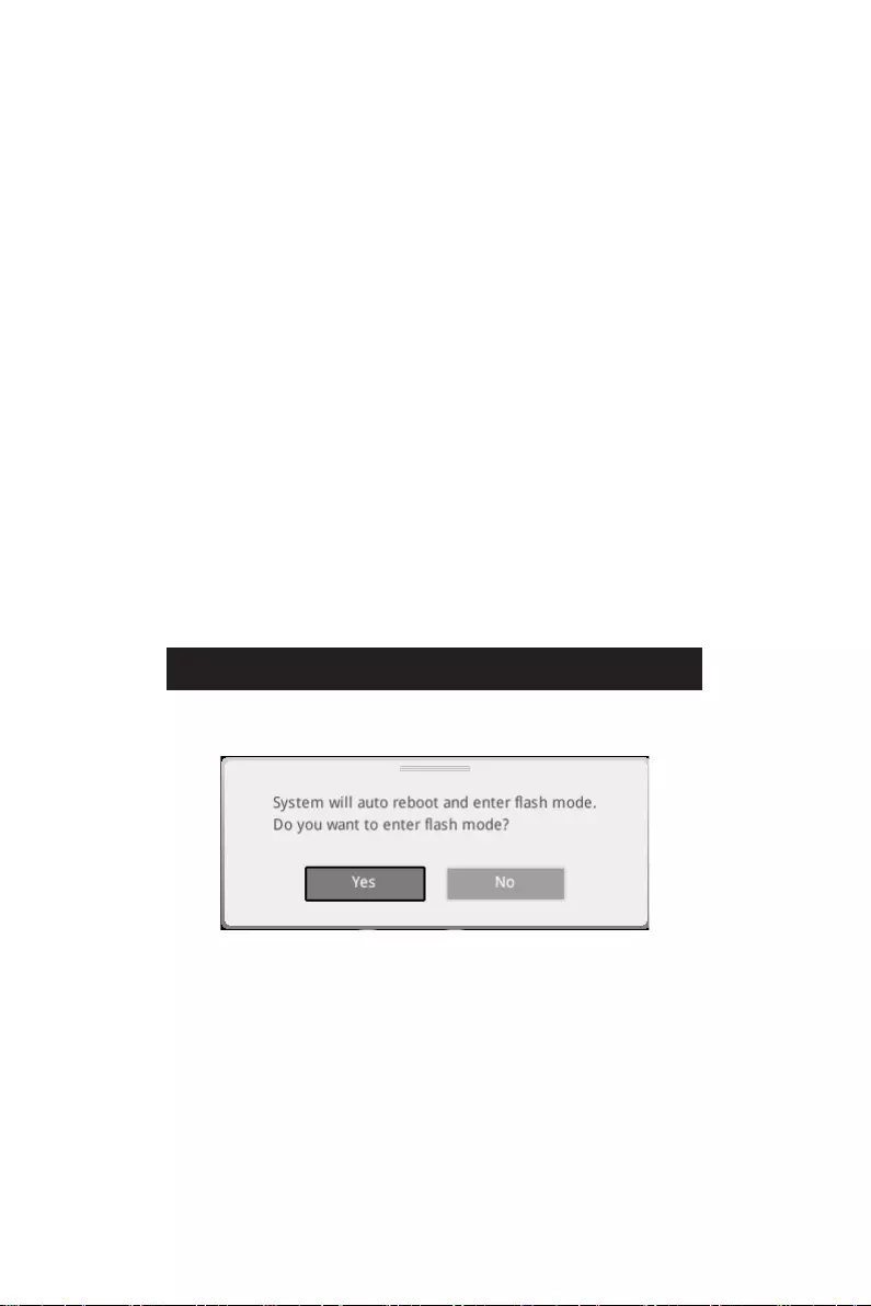
Updating BIOS:
1. Insert the USB flash drive that contains the update file into the USB port.
2. Please refer the following methods to enter flash mode.
▪Reboot and press Ctrl + F5 key during POST and click on Yes to reboot the
system.
▪Reboot and press Del key during POST to enter BIOS. Click the M-FLASH button
and click on Yes to reboot the system.
3. Select a BIOS file to perform the BIOS update process.
4. When prompted click on Yes to start recovering BIOS.
5. After the flashing process is 100% completed, the system will reboot
automatically.
36 UEFI BIOS
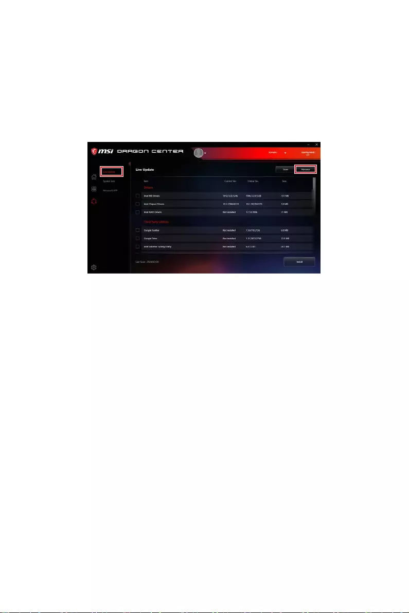
Updating the BIOS with MSI DRAGON CENTER
Before updating:
Make sure the LAN driver is already installed and the internet connection is set
properly.
Updating BIOS:
1. Install and launch MSI DRAGON CENTER and go to Support page.
2. Select Live Update and click on Advance button.
3. Click on Scan button to search the latest BIOS file.
4. Select the BIOS file and click on Download icon to download and install the latest
BIOS file.
5. Click Next and choose In Windows mode. And then click Next and Start to start
updating BIOS.
6. After the flashing process is 100% completed, the system will restart
automatically.
37
UEFI BIOS
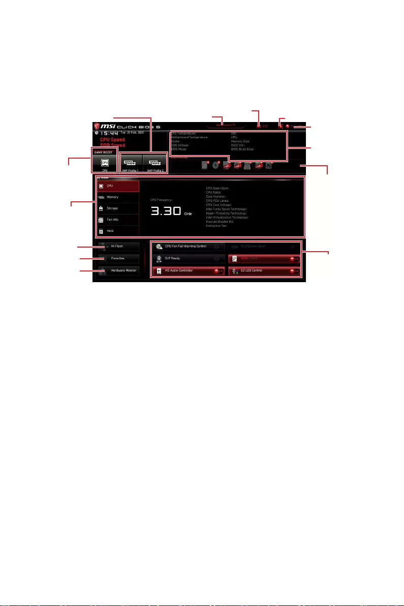
EZ Mode
At EZ mode, it provides the basic system information and allows you to configure the
basic setting. To configure the advanced BIOS settings, please enter the Advanced
Mode by pressing the Setup Mode switch or F7 function key.
XMP Profile
Component
Information
System
information
Boot device
priority bar
Function
buttons
Language
GAME BOOST
Search
Screenshot
Setup Mode switch
Hardware
Monitor
Favorites
∙GAME BOOST
is only available when both of the motherboard and CPU are supporting this function.
⚠
Important
Please don’t make any changes in OC menu and don’t load defaults to keep the
optimal performance and system stability after activating the GAME BOOST function.
∙XMP Profile
function is only available when the system, memory and CPU are supporting this
function.
∙Setup Mode switchF7 key to switch between Advanced mode
and EZ mode.
∙ScreenshotF12 key to take a screenshot and save it to USB
flash drive (FAT/ FAT32 format only).
∙SearchCtrl+F keys to enter the search page. It allows you
to search by BIOS item name. Move the mouse over a blank space and right click the
mouse to exit the search page.
⚠
Important
In search page, only the F6, F10 and F12 function keys are available.

38 UEFI BIOS
∙Language
∙System information
type, memory size, CPU/ DDR voltage, BIOS version and build date.
∙Boot device priority bar
The boot priority from high to low is left to right.
∙Component Information CPU, Memory, Storage, Fan Info and Help
buttons to show the information of connected component.
∙Function buttons
The function is enabled when the button shows ON .
⚠
Important
The function buttons will vary with the motherboard you purchased.
∙M-FlashM-Flash menu that provides the way to
update BIOS with a USB flash drive.
∙Hardware MonitorHardware Monitor menu that
allows you to manually control the fan speed by percentage.
39
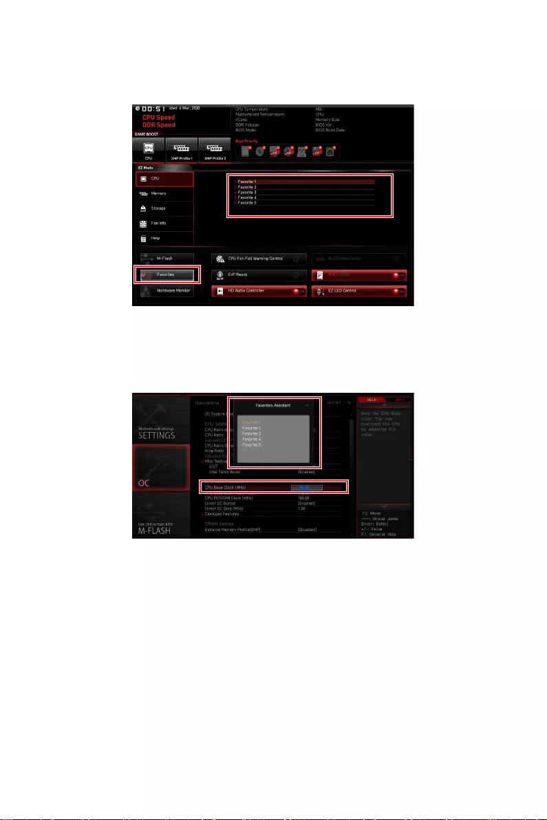
UEFI BIOS
∙Favorites F3 key to show the Favorites window.
It provides 5 menus for you to create personal BIOS menu where you can save and
access favorite/ fre
▪To add a BIOS item to a favorite menu
1. Select a BIOS item not only on BIOS menu but also on search page.
2. F2 key.
3. Choose a favorite page and click on OK.

40 UEFI BIOS
▪To delete a BIOS item from favorite menu
1. Select a BIOS item on favorite menu.
2. F2 key.
3. Choose Delete and click on OK.
41
UEFI BIOS
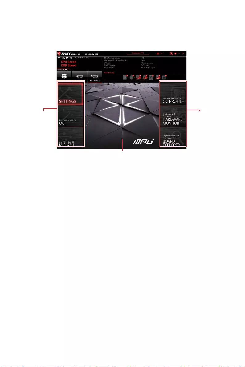
Advanced Mode
Press Setup Mode switch or F7 function key can switch between EZ Mode and
Advanced Mode in BIOS setup.
BIOS menu
selection
Menu display
BIOS menu
selection
∙BIOS menu selection
▪SETTINGS
▪OC
may get better performance.
▪M-FLASH
▪OC PROFILE
▪HARDWARE MONITOR
voltages of system.
▪BOARD EXPLORER
motherboard.
∙Menu display

42 UEFI BIOS
OC Menu
This menu allows you to configure the frequencies and voltages for overclocking.
Please note that, higher frequency and voltage may benefit overclocking capability but
⚠
Important
∙
Overclocking your PC manually is only recommended for advanced users.
∙
Overclocking is not guaranteed, and if done improperly, it could void your warranty
or severely damage your hardware.
∙
If you are unfamiliar with overclocking, we advise you to use GAME BOOST function
for easy overclocking.
∙
The BIOS items in OC menu will vary with the processor.
▶OC Explore Mode [Expert]
Enables or disables to show the normal or expert version of OC settings.
[Normal] Provides the regular OC settings in BIOS setup.
[Expert] Provides the advanced OC settings for OC expert to configure in BIOS
setup.
Note: We use * as the symbol for the OC settings of Expert mode.
▶CPU Ratio Apply Mode [All Core]*
Sets applied mode for CPU ratio. This item only appears when a CPU that supports
Turbo Boost is installed.
▶CPU Ratio [Auto]
Sets the CPU ratio that is used to determine CPU clock speed. This item only appears
when CPU Ratio Apply Mode set to All Core.
▶X-Core Ratio Limit [Auto]
Allows you to set the CPU ratios for different number of active cores. These items only
appear when CPU Ratio Apply Mode set to Turbo Ratio.
▶Numbers of CPU Cores of Group X [Auto]*
Sets the number of CPU cores as a group to run target CPU Turbo Ratio. The next
group should be more than former one in CPU core number. These items only appear
when CPU Ratio Apply Mode set to Turbo Ratio.
▶Target CPU Turbo Ratio Group X [Auto]
Sets the target CPU Turbo ratio value for assigned CPU cores group. The target CPU
Turbo Ratio value should not be higher than former one. These items only appear
when CPU Ratio Apply Mode set to Turbo Ratio.
▶Adjusted CPU Frequency

43
UEFI BIOS
▶Core X X of X xxxx MHz [Auto]
Allows you to set the CPU ratios for different number of active cores. These items only
appear when CPU Ratio Apply Mode set to Per Core.
▶ Turbo Ratio Oset Value [Auto]
Sets the CPU Turbo ratio offset value. This item only appears when CPU Ratio Apply
Mode set to Turbo Ratio Offset.
▶CPU Ratio Mode [Dynamic Mode]*
Selects the CPU Ratio operating mode. This item will appear when you set the CPU
ratio manually.
[Fixed Mode] Fixes the CPU ratio.
[Dynamic Mode] CPU ratio will be changed dynamically according to the CPU
loading.
▶ CPU Ratio Oset When Running AVX [Auto]
Sets a offset value to lower the CPU core ratio. It could be helpful for heat dissipation
when running AVX instructions. When set to Auto, BIOS will configure this setting
automatically. This item appears when the installed CPU supports this function.
▶Ring Ratio [Auto]
Sets the ring ratio. The valid value range depends on the installed CPU.
▶Adjusted Ring Frequency
▶GT Ratio [Auto]
Sets the integrated graphics ratio. The valid value range depends on the installed
CPU.
▶Adjusted GT Frequency
▶+Misc Setting*
▶CPU Base Clock (MHz) [Default]
Sets the CPU Base clock. You may overclock the CPU by adjusting this value. Please
note that overclocking behavior and stability is not guaranteed. This item appears
when a CPU that support this function is installed.
▶CPU Base Clock Apply Mode [Auto]*
Sets the applying mode for adjusted CPU base clock.
[Auto] This setting will be configured automatically by BIOS.
[Next Boot] CPU will run the adjusted CPU base clock next boot.
[Immediate] CPU runs the adjusted CPU base clock immediately.
▶Clockgen Features sub-menu
Press Enter

44 UEFI BIOS
▶ Extreme Memory Prole (XMP) [Disabled]
XMP (Extreme Memory Profile) is the overclocking technology by memory module.
Please enable XMP or select a profile of memory module for overclocking the
memory. This item will be available when the memory modules that support XMP is
installed.
▶DRAM Reference Clock [Auto]*
Sets the DRAM reference clock. The valid value range depends on the installed CPU.
This item appears when a CPU that supports this adjustment is installed.
▶DRAM Frequency [Auto]
Sets the DRAM frequency. Please note the overclocking behavior is not guaranteed.
▶Adjusted DRAM Frequency
▶Load Memory Presets [Disabled]*
Load OC Memory Preset will optimize the timing, voltage of installed memory module.
▶Memory Try It ! [Disabled]
It can improve memory compatibility or performance by choosing optimized memory
preset.
▶DRAM Timing Mode [Link]
Selects the memory timing mode.
[Link] Allows user to configure the DRAM timing for all memory channel.
[UnLink] Allows user to configure the DRAM timing for respective memory
channel.
▶ Advanced DRAM Conguration
Press Enter
memory channel. The system may become unstable or unbootable after changing
memory timing. If it occurs, please clear the CMOS data and restore the default
settings. (Refer to the Clear CMOS jumper/ button section to clear the CMOS data, and
enter the BIOS to load the default settings.)
▶Memory Fast Boot [Auto] *
Enables or disables the initiation and training for memory every booting.
[Auto] The setting will be configured automatically by BIOS.
[Enabled] System will completely keep the archives of first intiation and training
for memory. So the memory will not be initialed and trained when
booting to accelerate the system booting time.
[Disabled] The memory will be initialed and trained every booting.
▶DigitALL Power sub-menu
Press Enter
conditions about voltage/ current/ temputure for CPU.
▶CPU Core/ GT Voltage Mode [Auto]*
Sets the CPU Core/ GT voltage mode.

45
UEFI BIOS
▶CPU Core Voltage Mode [Auto]*
Sets the CPU Core voltage mode.
▶CPU Voltages control [Auto]
These options allow you to set the voltages related to CPU. If set to Auto, BIOS will set
these voltages automatically or you can set it manually.
▶DRAM Voltages control [Auto]
These options allow you to set the voltages related to memory. If set to Auto, BIOS
will set these voltages automatically or you can set it manually.
▶PCH Voltages control [Auto]
These options allow you to set the voltages related to PCH. If set to Auto, BIOS will set
these voltages automatically or you can set it manually.
▶CPU Memory Changed Detect [Enabled]*
Enables or disables the system to issue a warning message during boot when the CPU
or memory has been replaced.
[Enabled] The system will issue a warning message during boot and then you have
to load the default settings for new devices.
[Disabled] Disables this function and keeps the current BIOS settings.
▶OC Quick View Timer [3 Sec]*
Sets the duration of OC setting values showed on the screen. If set to Disabled, BIOS
will not show the variations of OC setting.
▶ CPU Specications sub-menu
Press Enter
installed CPU. You can also access this information menu at any time by pressing [F4].
Read only.
▶MEMORY-Z sub-menu
Press Enter
timings of installed memory. You can also access this information menu at any time by
pressing [F5].
▶CPU Features sub-menu
Press Enter
technologies to protect CPU and improve the system performance.

46 UEFI BIOS

1
Inhalt
Inhalt
Sicherheitshinweis …………………………………………………………………………………… 3
Spezifikationen ………………………………………………………………………………………… 4
Packungsinhalt ……………………………………………………………………………………… 10
Rückseite E/A ………………………………………………………………………………………… 11
LAN Port LED Zustandstabelle …………………………………………………………………. 11
Konfiguration der Audioanschlüsse …………………………………………………………… 11
Realtek Audio Console …………………………………………………………………………….. 12
Übersicht der Komponenten ……………………………………………………………………. 15
CPU Sockel …………………………………………………………………………………………….. 16
DIMM Steckplätze ……………………………………………………………………………….17
PCI_E1~4: PCIe Erweiterungssteckplätze ………………………………………………….. 18
CPU_PWR1, ATX_PWR1: Stromanschlüsse ……………………………………………….. 19
…………………………………………………………. 20
JAUD1: Audioanschluss des Frontpanels …………………………………………………… 20
M2_1~2: M.2 Steckplätze (Key M) ……………………………………………………………… 21
SATA1~6: SATA 6Gb/s Anschlüsse …………………………………………………………….. 23
CPU_FAN1, PUMP_FAN1, SYS_FAN1~6: Stromanschlüsse für Lüfter ………….. 24
JUSB1~2: USB 2.0 Anschlüsse ………………………………………………………………….. 25
…………………………………………………….. 25
JUSB3: USB 3.2 Gen 1 Anschluss ……………………………………………………………… 26
……………………………….. 27
JRTD3: Intel RTD3 Anschluss……………………………………………………………………. 27
JBAT1: Clear CMOS Steckbrücke (Reset BIOS) …………………………………………… 28
JTPM1: TPM Anschluss ……………………………………………………………………………. 28
JCI1: Gehäusekontaktanschluss ……………………………………………………………….. 29
JRGB1~2: RGB LED Anschlüsse ……………………………………………………………….. 30
JRAINBOW1~2: Adressierbare RGB LED Anschlüsse ………………………………….. 31
Onboard-LEDs ……………………………………………………………………………………….. 32
EZ Debug LED …………………………………………………………………………………………. 32
………………………………………………………………….. 32
Installation von OS, Treibern und Utilities …………………………………………………. 33
Installation von Windows® 10 ……………………………………………………………………. 33
Installation von Treibern ………………………………………………………………………….. 33
Installation von Utilities ……………………………………………………………………………. 33
UEFI BIOS ………………………………………………………………………………………………. 34
BIOS Setup ……………………………………………………………………………………………… 35
Öffnen des BIOS Setups……………………………………………………………………………. 35

2Inhalt
Reset des BIOS ……………………………………………………………………………………….. 36
Aktualisierung des BIOS …………………………………………………………………………… 36
EZ Modus ……………………………………………………………………………………………….. 38
Erweiterter Modus ………………………………………………………………………………….. 41
OC Menü…………………………………………………………………………………………………. 42

3
Sicherheitshinweis
Sicherheitshinweis
∙Die im Paket enthaltene Komponenten sind der Beschädigung durch
elektrostatischen Entladung (ESD). Beachten Sie bitte die folgenden Hinweise, um die
erfolgreichen Computermontage sicherzustellen.
∙Stellen Sie sicher, dass alle Komponenten fest angeschlossen sind. Lockere
Steckverbindungen können Probleme verursachen, zum Beispiel: Der Computer
erkennt eine Komponente nicht oder startet nicht.
∙Halten Sie das Motherboard nur an den Rändern fest, und verhindern Sie die
Berührung der sensiblen Komponenten.
∙Um eine Beschädigung der Komponenten durch elektrostatische Entladung
(ESD) zu vermeiden, sollten Sie eines elektrostatischen Armbands während der
Handhabung des Motherboards tragen. Wenn kein elektrostatischen Handgelenkband
vorhanden ist, sollten Sie Ihre statische Elektrizität ableiten, indem Sie ein anderes
Metallobjekt berühren, bevor Sie das Motherboard anfassen.
∙Bewahren Sie das Motherboard in einer elektrostatische Abschirmung oder einem
Antistatiktuch auf, wenn das Motherboard nicht installiert ist.
∙Überprüfen Sie vor dem Einschalten des Computers, dass sich keine losen
Schrauben und andere Bauteile auf dem Motherboard oder im Computergehäuse
befinden.
∙Bitte starten Sie den Computer nicht, bevor die Installation abgeschlossen ist.
Dies könnte permanente Schäden an den Komponenten sowie zu das Verletzung des
Benutzers verursachen.
∙Sollten Sie Hilfe bei der Installation benötigen, wenden Sie sich bitte an einen
∙Schalten Sie die Stromversorgung aus und ziehen Sie das das Stromkabel ab, bevor
∙Bewahren Sie die Bedienungsanleitung als künftige Referenz auf.
∙Halten Sie das Motherboard von Feuchtigkeit fern.
∙Bitte stellen Sie sicher, dass Ihre Netzspannung den Hinweisen auf dem Netzteil vor
Anschluss des Netzteils an die Steckdose entspricht.
∙Verlegen Sie das Netzkabel so, dass niemand versehentlich darauf treten kann.
Stellen Sie nichts auf dem Netzkabel ab.
∙
∙Falls einer der folgenden Umstände eintritt, lassen Sie bitte das Motherboard von
Kundendienstpersonal prüfen:
▪Flüssigkeit ist in dem Computer eingedrungen.
▪Das Motherboard wurde Feuchtigkeit ausgesetzt.
▪Das Motherboard funktioniert nicht richtig oder Sie können es nicht wie in der
Bedienungsanleitung beschrieben bedienen.
▪Das Motherboard ist heruntergefallen und beschädigt.
▪Das Motherboard weist offensichtlich Zeichen eines Schadens auf.
∙Nutzen und lagern Sie das Gerät nicht an Stellen, an denen Temperaturen von mehr

4Spezifikationen
Spezifikationen
CPU
Unterstützt Intel® Core™ der 10. Generation Prozessoren und
Pentium® Gold / Celeron® Prozessoren für Sockel LGA 1200*
* Weitere Kompatibilitätsinformationen finden Sie unter www.intel.com.
verwendet werden.
Chipsatz Intel® Z490 Chipsatz
Speicher
∙4x DDR4 Speicherplätze, aufrüstbar bis 128 GB*
∙Unterstützt 1R 2133/2666/2933 MHz*
▪1DPC 1R max. Übertragungsraten bis zu 4800+ MHz
▪1DPC 2R max. Übertragungsraten bis zu 4266+ MHz
▪2DPC 1R max. Übertragungsraten bis zu 4400+ MHz
▪2DPC 2R max. Übertragungsraten bis zu 4000+ MHz
∙
∙
∙Unterstützt Intel® Extreme Memory Profile (XMP)
* Weitere Informationen zu kompatiblen Speicher finden Sie unter:
http://www.msi.com
Erweiterung-
anschlüsse
∙1x PCIe 3.0 x16 Steckplatz (vom CPU)
∙1x PCIe 3.0 x16 Steckplatz (x4 Modus, von PCH)
∙2x PCIe x1 Steckplätze (von PCH)
Onboard-Grafik
∙1x HDMI Anschluss, Unterstützung einer maximalen
Auflösung von 4096×2160 @ 30Hz
∙1x DisplayPort Anschluss, Unterstützung einer maximalen
Auflösung von 4096 x 2304 @ 60Hz
Multi-GPU ∙™ Technologie
Fortsetzung auf der nächsten Seite

5
Spezifikationen
Fortsetzung der vorherigen Seite
Aufbewahrung
Intel® Z490 Chipsatz
∙6x SATA 6Gb/s Anschlüsse*
∙2x M.2 Steckplätze (Key M)
▪Unterstützt bis zu PCIe 3.0 x4 und SATA 6Gb/s
▪M2_1 Steckplatz unterstützt 2242/ 2260 /2280/ 22110
Speichergeräte*
▪M2_2 Steckplatz unterstützt 2242/ 2260 /2280
Speichergeräte**
▪Intel® Optane™ Technik***
* SATA2 wird nicht zur Verfügung stehen, wenn Sie eine M.2 SATA SSD im M2_1
Steckplatz installieren.
** SATA5 & SATA6 werden nicht zur Verfügung stehen, wenn Sie eine M.2 SATA/
PCIe SSD im M2_2 Steckplatz installieren.
*** Bevor Sie Intel® Optane™ Speichermodule verwenden, stellen Sie bitte über
Downloads von der MSI Website sicher, dass die Treiber und das BIOS auf dem
neuesten Stand sind.
RAID
Intel® Z490 Chipsatz
∙Unterstützt RAID 0, RAID1, RAID 5 und RAID 10 für SATA
Speichergeräte
∙Unterstützt RAID 0 und RAID 1 für M.2 PCIe
Speichergeräte
LAN
USB
∙Intel® Z490 Chipsatz
▪1x USB 3.2 Gen 2 10Gbit/s
rückseitigen Anschlussleiste
▪7x USB 3.2 Gen 1 5Gbit/s
der rückseitigen Anschlussleiste, 2 stehen durch die
Anschluss)
▪2x USB 2.0 Anschlüsse an der rückseitigen
Anschlussleiste
▪4x USB 2.0 Anschlüsse stehen durch die internen USB
∙ASMedia® ASM3241
▪1x USB 3.2 Gen 2×2 20Gbit/s
rückseitigen Anschlussleiste
Audio
∙
∙
Fortsetzung auf der nächsten Seite

6Spezifikationen
Fortsetzung der vorherigen Seite
Wireless/ Bluetooth
Intel® AX201
∙
bis zu 2.4Gbit/s
∙802.11ac; WiFi 6 ist vorzertifiziert
∙Bluetooth 5.1, FIPS, FISMA
∙
Hintere Ein-/ und
Ausgänge
∙
∙2x USB 2.0 Anschlüsse
∙1x Display Anschluss
∙1x HDMI Anschluss
∙
∙
∙1x LAN (RJ45) Anschluss
∙
∙
∙
∙5x Audiobuchsen
Interne Anschlüsse
∙
∙
∙
∙6x SATA 6Gb/s Anschlüsse
∙
∙1x USB 3.2 Gen 1 5Gbit/s Anschluss (unterstützt
zusätzliche 2 USB 3.2 Gen 1 5Gbit/s Anschlüsse)
∙2x USB 2.0 Anschlüsse (unterstützt zusätzliche 4 USB 2.0
Anschlüsse)
∙
∙1x 4
∙
∙1x Audioanschluss des Frontpanels
∙
∙1x Gehäusekontaktschalter
∙1x Clear CMOS Steckbrücke
Fortsetzung auf der nächsten Seite

7
Spezifikationen
Fortsetzung der vorherigen Seite
Interne Anschlüsse
∙Anschlüsse
∙Anschlüsse
∙1x TPM Anschluss
∙1x TBT Anschluss*
∙1x RTD3 Anschluss
LED Funktionen ∙1x LED Steuerung
∙4x EZ Debug LED
E/A Anschluss NUVOTON NCT6687 Controller Chip
Hardware Monitor
∙CPU/System Temperaturerfassung
∙CPU/System Geschwindigkeitserfassung
∙CPU/System Lüfterdrehzahlregelung
Formfaktor ∙ATX Formfaktor
∙12 Zoll x 9,6 Zoll (30,5 cm x 24,4 cm)
BIOS Funktionen
∙1x 256 Mb Flash
∙UEFI AMI BIOS
∙ACPI 6.2, SM BIOS 3.2
∙Mehrsprachenunterstützung
Software
∙Treiber
∙DRAGON CENTER
∙Intel Extreme Tuning Utility
∙MSI App Player (BlueStacks)
∙Open Broadcaster Software (OBS)
∙
∙Google Chrome™, Google Toolbar, Google Drive
∙Norton™ Internet Security Solution
Fortsetzung auf der nächsten Seite

8Spezifikationen
Fortsetzung der vorherigen Seite
Dragon Center
Funktionen
∙Gaming Modus
∙Gaming Hotkey
∙LAN Manager
∙Mystic Light
∙Ambient Link
∙
∙Monitor(Hardware
Monitor)
∙True Color
∙Live Update
∙DPC Latency Tuner
∙Speed Up
∙Smart Tool
∙Super Charger
Weitere Informationen finden Sie
unter http://download.msi.com/
manual/mb/DRAGONCENTER2.pdf
Besondere
Funktionen
∙Audio
▪Audio Boost
∙Netzwerk
▪2.5G LAN
▪LAN Manager
▪Intel WiFi
∙Kühlung
▪Extended Heatsink Design
▪M.2 Shield Frozr
▪Lüfter
▪Smart Lüftersteuerung
Fortsetzung auf der nächsten Seite

9
Spezifikationen
Fortsetzung der vorherigen Seite
Besondere
Funktionen
∙LED
▪Mystic Light
▪Mystic Light Extension (RGB)
▪Mystic Light Extension (RAINBOW)
▪Mystic Light Sync
▪EZ DEBUG LED
▪EZ LED Steuerung
∙Schutz
▪PCIe Steel Armor
▪Vorinstallierte Anschlussblende
∙Leistung
▪
▪DDR4 Boost
▪Core Boost
▪GAME Boost
▪Lightning USB 20G
▪USB 3.2 Gen 2 10G
▪USB Anschluss mit Typ A+C
▪
▪Dual CPU Power
∙Erfahrung
▪DRAGON CENTER
▪Click BIOS 5
10 Packungsinhalt
Packungsinhalt
Überprüfen Sie den Packungsinhalt des Mainboards. Die Packung sollte enthalten:
Motherboard MPG Z490 GAMING EDGE WIFI
Dokumentation
Benutzerhandbuch 1
1
Schnellinstallationsanleitung 1
Anwendung 1
Kabel SATA 6G Kabel (2 Kabel pro Packung) 1
Zubehör
1
1
1
Produktregistrierungskarte 1
M.2 Schraube (3 Stück pro Packung) 1
⚠
Wichtig
Falls einer der oben aufgeführten Artikel beschädigt ist oder fehlt, wenden Sie sich
bitte an Ihren Händler.
11
Rückseite E/A
Rückseite E/A
Audioanschlüsse
Ausgang
anschlüsse
PS/2
HDMI
Anschluss
Displayport
USB 2.0
2,5Gbit/s LAN
USB 3.2 Gen 2 10Gbit/s
USB 3.2 Gen 1 5Gbit/s
USB 3.2 Gen 2×2 20Gbit/s
Konfiguration der Audioanschlüsse
Audioanschlüsse Kanal
2468
Hinterer Lautsprecher
Lautsprecher
Lautsprecher
Blank: Leer)
Verbindung/ Aktivität LED
Zustand Bezeichnung
Aus Keine Verbindung
Gelb Verbindung
Blinkt Datenaktivität
Geschwindigkeit LED
Zustand Bezeichnung
Aus
Grün
Orange
LAN Port LED Zustandstabelle
12 Rückseite E/A
Realtek Audio Console
Audioeinstellungen verändern, um ein optimales Klangerlebnis erzeugen.
∙Geräteauswahl
aktivierte Gerät ist mit einem Haken gekennzeichnet.
∙Optimierungen
∙Lautstärke
∙Verbindungsstatus
∙Anschlüsse
Auto Popup-Dialog
fragt nach einer Bestätigung für das angeschlossene Gerät.
Jede Buchse entspricht diesem Wert der Grundeinstellung, wie es auf den nächsten
Seiten gezeigt wird.
⚠
Wichtig
Die obige Bilder stellen lediglich Referenzen dar und können von dem von Ihnen
erworbenen Produkt abweichen.
Verbindungsstatus
Anschluss
Geräteauswahl
Lautstärke
Optimierungen

13
Rückseite E/A
Audiobuchsen für den Anschluss von einem Kopfhörer und Mikrofon
Audiobuchsen für Stereo-Lautsprecher
Audiobuchsen für 7.1 Kanal Anlage
AUDIO INPUT
AUDIO INPUT
Rear Front
Side Center/
Subwoofer
14 Rückseite E/A
Antennen installieren
1. Schrauben Sie die Antennen fest an die Antennenanschlüsse, wie gezeigt.
2. Richten Sie die Antennenspitzen aus.
1
2

15
Übersicht der Komponenten
Übersicht der Komponenten
DIMMA1
CPU_FAN1
DIMMA2
DIMMB1
DIMMB2
JRGB2
JRAINBOW2
PUMP_FAN1
SYS_FAN6
SYS_FAN5
SYS_FAN1
SYS_FAN4
LED_SW1
JRTD3
JFP1
JTBT1
SATA6
SATA5
JTPM1
JUSB1
JUSB2
JFP2
JT1
JBAT1
JRAINBOW1
ATX_PWR1
JUSB4
JUSB3
CPU Sockel
CPU_PWR1
CPU_PWR2
SYS_FAN3
SYS_FAN2
JRGB1
JAUD1
PCI_E4
PCI_E3
M2_2
M2_1
JCI1
PCI_E2
PCI_E1
16 Übersicht der Komponenten
⚠
Wichtig
∙
∙
Bitte bewahren Sie die CPU Schutzkappe nach der Installation des Prozessors auf.
MSI wird RMA (Return Merchandise Authorization) Anfragen nur dann behandeln,
∙
und die Systemstabilität zu gewährleisten.
∙
Stellen Sie sicher, dass Ihr Kühlkörper eine feste Verbindung mit der CPU
hergestellt hat, bevor Sie Ihr System starten.
∙
Überhitzung beschädigt die CPU und das System nachhaltig. Stellen Sie stets eine
korrekte Funktionsweise des CPU Kühlers sicher, um die CPU vor Überhitzung zu
schützen. Stellen Sie sicher, dass eine gleichmäßige Schicht thermischer Paste oder
thermischen Tapes zwischen der CPU und dem Kühlkörper vorhanden ist, um die
Wärmeableitung zu erhöhen.
∙
installiert ist.
∙
Verwenden Sie bitte die Installationsanweisung des Kühlkörpers/Kühlers, falls Sie
eine seperate CPU oder einen Kühlkörper/ Kühler erworben haben.
∙
Dieses Motherboard wurde so entworfen, dass es Übertakten unterstützt. Stellen
Sie jedoch bitte sicher, dass die betroffenen Komponenten mit den abweichenden
Einstellungen während des Übertaktens zurecht kommen. Von jedem Versuch
des Betriebes außerhalb der Produktspezifikationen kann nur abgeraten werden.
MSI übernehmt keinerlei Garantie für die Schäden und Risiken, die aus einem
unzulässigem Betrieb oder einem Betrieb außerhalb der Produktspezifikation
resultieren.
CPU Sockel
Erklärung zur LGA 1200 CPU
Die Oberseite der LGA 1200 CPU hat vier
Justierungen und ein goldenes Dreieck
um die korrekte Ausrichtung der CPU
auf dem Motherboard zu gewährleisten.
Das goldene Dreieck des Prozessors
definiert die Position des ersten Pins.
50,6 mm
Abstand zwischen der Mitte der
CPU und dem nächsten DIMM-
Steckplatz.

17
Übersicht der Komponenten
DIMM Steckplätze
DIMMA1 DIMMB1
Kanal A Kanal B
DIMMA2 DIMMB2
Speichermodul-Installationsempfehlung
⚠
Wichtig
∙
AUm einen sicheren Systemstart zu gewährleisten, bestücken Sie immer DIMMA2
zuerst.
∙
Typs und identischer Speicherdichte in den DIMM Slots unterschiedlicher Kanäle
verwenden.
∙
Einige Speichermodule können beim Übertakten auf einer niedrigeren Frequenz
DRAM Frequency die Speicherfrequenz ein, wenn Sie
mit der festgelegten oder einer höheren Speicherfrequenz arbeiten möchten.
∙
Es wird empfohlen, ein effizienteres Speicherkühlsystem bei einer Vollbestückung
des DIMMs oder beim Übertakten zu verwenden.
∙
Die Stabilität und Kompatibilität beim Übertakten der installierten Speichermodule
sind abhängig von der installierten CPU und den installierten Geräten.
∙
Weitere Informationen zu kompatiblen Speichermodulen finden Sie unter:
http://www.msi.com
DIMMB2 DIMMB2
DIMMB1
DIMMA2 DIMMA2 DIMMA2
DIMMA1

18 Übersicht der Komponenten
PCI_E1~4: PCIe Erweiterungssteckplätze
⚠
Wichtig
∙
Wenn Sie eine große und schwere Grafikkarte einbauen, benötigen Sie einen
Grafikkarten-Stabilisator (Graphics Card Bolster) der das Gewicht trägt und eine
Verformung des Steckplatzes vermeidet.
∙
Für die Installation einer einzelnen PCIe x16 Erweiterungskarte mit optimaler
Leistung, empfehlen wir den PCI_E1 Steckplatz zu verwenden.
∙
Achten Sie darauf, dass Sie den Strom abschalten und das Netzkabel aus der
Steckdose herausziehen, bevor Sie eine Erweiterungskarte installieren oder
entfernen. Lesen Sie bitte auch die Dokumentation der Erweiterungskarte, um
PCI_E1: PCIe 3.0 x16 (CPU)
PCI_E3: PCIe 3.0 x4 (PCH)
PCI_E2: PCIe 3.0 x1 (PCH)
PCI_E4: PCIe 3.0 x1 (PCH)

19
Übersicht der Komponenten
24
131
12
ATX_PWR1
1 +3.3V 13 +3.3V
2 +3.3V 14
3 Ground 15 Ground
4 +5V 16
5 Ground 17 Ground
6 +5V 18 Ground
7 Ground 19 Ground
8 PWR OK 20 Res
9 5VSB 21 +5V
10 +12V 22 +5V
11 +12V 23 +5V
12 +3.3V 24 Ground
5
4 1
8CPU_PWR1
1 Ground 5 +12V
2 Ground 6 +12V
3 Ground 7 +12V
4 Ground 8 +12V
⚠
Wichtig
Stellen Sie sicher, dass alle Anschlüsse mit den richtigen Anschlüssen des Netzteils
verbunden sind, um einen stabilen Betrieb der Hauptplatine sicherzustellen.
CPU_PWR1, ATX_PWR1: Stromanschlüsse
Mit diesen Anschlüssen verbinden Sie die ATX Stromstecker.
3
2 1
4CPU_PWR2
1 Ground 3 +12V
2 Ground 4 +12V
20 Übersicht der Komponenten
JFP1, JFP2: Frontpanel-Anschlüsse
Diese Anschlüsse verbinden die Schalter und LEDs des Frontpanels.
1
2 10
9
+
+
+
+
Power LED
HDD LED Reset Switch
Reserved
Power Switch
JFP1
1 HDD LED + 2 Power LED +
3 4
5 Reset Switch 6 Power Switch
7 Reset Switch 8 Power Switch
9 Reserved 10 No Pin
1
JFP2
+
+
Speaker
Buzzer 1 2 Buzzer +
3 4 Speaker +
JAUD1: Audioanschluss des Frontpanels
Dieser Anschluss ermöglicht den Anschluss von Audiobuchsen eines Frontpanels.
1
2 10
9
1 MIC L 2 Ground
3 MIC R 4 NC
5 Head Phone R 6 MIC Detection
7 SENSE_SEND 8 No Pin
9 Head Phone L 10 Head Phone Detection

21
Übersicht der Komponenten
M2_1~2: M.2 Steckplätze (Key M)
⚠
Wichtig
∙
Intel® RST unterstützt nur PCIe M.2 SSD mit UEFI ROM.
∙
Intel® Optane
™
Technik unterstützt alle M.2 Steckplätze.
⚽
Video-Demonstration
Eine anschauliche Darstellung zur
Installation eines M.2 Moduls finden Sie
im Video.
1
1
2
Installation eines M.2 Moduls
1.
2.
Wärmeleitpads.

22 Übersicht der Komponenten
30º30º
5
4
3
8,5H Schraube
Abstandshalter
3. Wählen Sie die Montageposition entsprechend Ihrer M.2 SSD Länge.
4. .
5.
6.
6
6

23
Übersicht der Komponenten
SATA1~6: SATA 6Gb/s Anschlüsse
Dieser Anschluss basiert auf der Hochgeschwindigkeitsschnittstelle SATA 6 Gb/s. Pro
Anschluss kann ein SATA Gerät angeschlossen werden.
⚠
Wichtig
∙
Folge sein.
∙
flachen Stecker auf dem Motherboard einstecken.
∙
SATA2 wird nicht zur Verfügung stehen, wenn Sie eine M.2 SATA SSD im M2_1
Steckplatz installieren.
∙
Die SATA5 und SATA6 Anschlüsse werden nicht zur Verfügung stehen, wenn Sie
eine M.2 SSD im M2_2 Steckplatz installieren.
SATA1
SATA3
SATA2
SATA4
SATA5
SATA6
Tabelle der M.2- und SATA-Gerätekombination
Steckplatz Verfügbare SATA Anschlüsse
M2_1 PCIe SATA PCIe SATA PCIe SATA
M2_2 PCIe PCIe SATA SATA
SATA1
SATA2
SATA3
SATA4
SATA5
SATA6
(SATA: M.2 SATA SSD, PCIe
24 Übersicht der Komponenten
CPU_FAN1, PUMP_FAN1, SYS_FAN1~6: Stromanschlüsse für Lüfter
Diese Anschlüsse können im PWM (Pulse Width Modulation) Modus
Lüfteranschlüsse konstante 12V Ausgang und regeln die Lüftergeschwindigkeit
Umschalten des Lüfter-Modus und Anpassung der Lüfterdrehzahl
Sie können unter BIOS > HARDWARE MONITOR
umschalten und die Lüfterdrehzahl ändern.
Wählen Sie den PWM- oder DC-Modus aus
⚠
Wichtig
Überprüfen Sie die ordnungsgemäße Funktion der Lüfter nach dem Umschalten des
Die Gradientenpunkte des Lüfterverlaufs erlauben die
Temperatur.
Pin-Belegung des PWM-Modus
1 Ground 2 +12V
3 Sense 4 Speed Control Signal
Pin-Belegung des DC-Modus
1 Ground 2 Voltage Control
3 Sense 4 NC
Pin-Belegung der Lüfteranschlüsse
Lüfteranschlüsse des Standard-DC-Modus
Lüfteranschlüsse
des Standard-PWM-
Modus
Lüfteranschlüsse
des Standard-Auto—
Modus
1
SYS_FAN4~6
1
SYS_FAN1~3
1
CPU_FAN1
1
PUMP_FAN1
25
Übersicht der Komponenten
JUSB1~2: USB 2.0 Anschlüsse
Mit diesen Anschlüssen können Sie die USB 2.0 Anschlüsse auf dem Frontpanel
verbinden.
1
2 10
9
1 VCC 2 VCC
3 4
5 USB0+ 6 USB1+
7 Ground 8 Ground
9 No Pin 10 NC
⚠
Wichtig
∙
Bitte beachten Sie, dass Sie die mit VCC (Stromführende Leitung) und Ground
(Erdung) bezeichneten Pins korrekt verbinden müssen, ansonsten kann es zu Schäden
kommen.
∙
Sie bitte die MSI® DRAGON CENTER Software.
JUSB4: USB 3.2 Gen 1 Typ-C Anschluss
Frontpanel verbinden. Der Anschluss verfügt über ein besonders sicheres Design.
Wenn Sie das Kabel anschließen, müssen Sie es in der entsprechenden Ausrichtung
verbinden.
JUSB4
Anschluss auf dem
Frontpanel
26 Übersicht der Komponenten
JUSB3: USB 3.2 Gen 1 Anschluss
Mit diesem Anschluss können Sie die USB 3.2 Gen 1 Anschlüsse auf dem Frontpanel
verbinden.
1
10 11
20
1 Power 11 USB2.0+
2 USB3_RX_DN 12
3 USB3_RX_DP 13 Ground
4 Ground 14 USB3_TX_C_DP
5 USB3_TX_C_DN 15 USB3_TX_C_DN
6 USB3_TX_C_DP 16 Ground
7 Ground 17 USB3_RX_DP
8 18 USB3_RX_DN
9 USB2.0+ 19 Power
10 NC 20 No Pin
⚠
Wichtig
Bitte beachten Sie, dass Sie die mit „Stromführende Leitung“ und „Erdleitung“
bezeichneten Pins korrekt verbinden müssen, ansonsten kann es zu Schäden
kommen.

27
Übersicht der Komponenten
JTBT1: Anschluss für Thunderbolt-Erweiterungskarte
Erweiterungskarte anschließen.
1
1 FORCE_PWR 2 SCI_EVENT
3 4
5 GND
JRTD3: Intel RTD3 Anschluss
1
1 WAKE 2 PWR EN
3 GND
28 Übersicht der Komponenten
JBAT1: Clear CMOS Steckbrücke (Reset BIOS)
Der Onboard CMOS Speicher (RAM) wird durch eine externe Spannungsversorgung
durch eine Batterie auf dem Motherboard versorgt, um die Daten der
Systemkonfiguration zu speichern. Wenn Sie die Systemkonfiguration löschen wollen,
müssen Sie die Steckbrücke für kurze Zeit umsetzen.
Daten
beibehalten
(Standardwert)
löschen/ Reset
des BIOS
Rücksetzen des BIOS auf Standardwerte
1. Schalten Sie den Computer ab und ziehen Sie das Netzkabel ab.
2. Verwenden Sie eine Steckbrücke, um JBAT1
3. Entfernen Sie die Steckbrücke von JBAT1.
4. Stecken Sie das Kabel Ihres Computers in die Steckdose hinein und schalten Sie
den Computer ein.
1
2 12
11
1 SPI Power 2 SPI Chip Select
3
Master In Slave Out (SPI Data)
4
Master In Slave In (SPI Data)
5 Reserved 6 SPI Clock
7 Ground 8 SPI Reset
9 Reserved 10 No Pin
11 Reserved 12 Interrupt Request
JTPM1: TPM Anschluss
Dieser Anschluss wird für das TPM Modul (Trusted Platform Module) verwendet.
Weitere Informationen über den Einsatz des optionalen TPM Modules entnehmen Sie
bitte dem TPM Plattform Handbuch.

29
Übersicht der Komponenten
JCI1: Gehäusekontaktanschluss
Dieser Anschluss wird mit einem Kontaktschalter verbunden.
Normal
(Standardwert) Löse den
Gehäuseeingriff aus
Gehäusekontakt-Detektor verwenden
1. Schließen Sie den JCI1
Gehäuse an.
2. Schließen Sie die Gehäuseabdeckung.
3. Gehen Sie zu BIOS > SETTINGS > Security > Chassis Intrusion Configuration.
4. Stellen Sie Chassis Intrusion auf Enabled.
5. Drücken Sie F10 zum Speichern und Beenden und drücken Sie dann die Enter
Taste, um Ja auszuwählen.
6. Bei eingeschaltetem Computer wird eine Warnmeldung auf dem Bildschirm
angezeigt, wenn die Gehäuseabdeckung wieder geöffnet wird.
Gehäusekontakt-Warnung zurücksetzen
1. Gehen Sie zu BIOS > SETTINGS > Security > Chassis Intrusion Configuration.
2. Stellen Sie Chassis Intrusion auf Reset.
3. Drücken Sie F10 zum Speichern und Beenden und drücken Sie dann die Enter
Taste, um Ja auszuwählen.
30 Übersicht der Komponenten
⚠
Wichtig
∙
R/B) mit der maximalen Leistung von 3 A (12 V).
∙
Schalten Sie die Stromversorgung aus und ziehen Sie das Netzkabel ab, bevor Sie
∙
JRGB1~2: RGB LED Anschlüsse
1
1 +12V 2 G
3 R 4 B
1
GRB
JRGB
Anschluss
RGB Verlängerungskabel
5050 RGB LED Streifen 12V
RGB-LED-Streifen anschließen
1
1
GRB
JRGB Anschluss
RGB-LED-Lüfteranschluss

31
Übersicht der Komponenten
JRAINBOW1~2: Adressierbare RGB LED Anschlüsse
1
1 +5V 2 Data
3 No Pin 4 Ground
1
1
1
D
+5V
⚠
ACHTUNG
⚠
Wichtig
∙
Der JRAINBOW Anschluss unterstützt bis zu 75 LEDs WS2812B einzeln
von 3 A (5 V). Bei einer Helligkeit von 20 Prozent unterstützt dieser Anschluss bis zu
200 LEDs.
∙
Schalten Sie die Stromversorgung aus und ziehen Sie das Netzkabel ab, bevor Sie
∙
JRAINBOW
Anschluss
JRAINBOW Anschluss
Rainbow RGB LED
Verlängerungskabel WS2812B einzeln adressierbare
Adressierbarer RGB-LED-Streifen anschließen
Adressierbarer RGB-LED-Lüfteranschluss
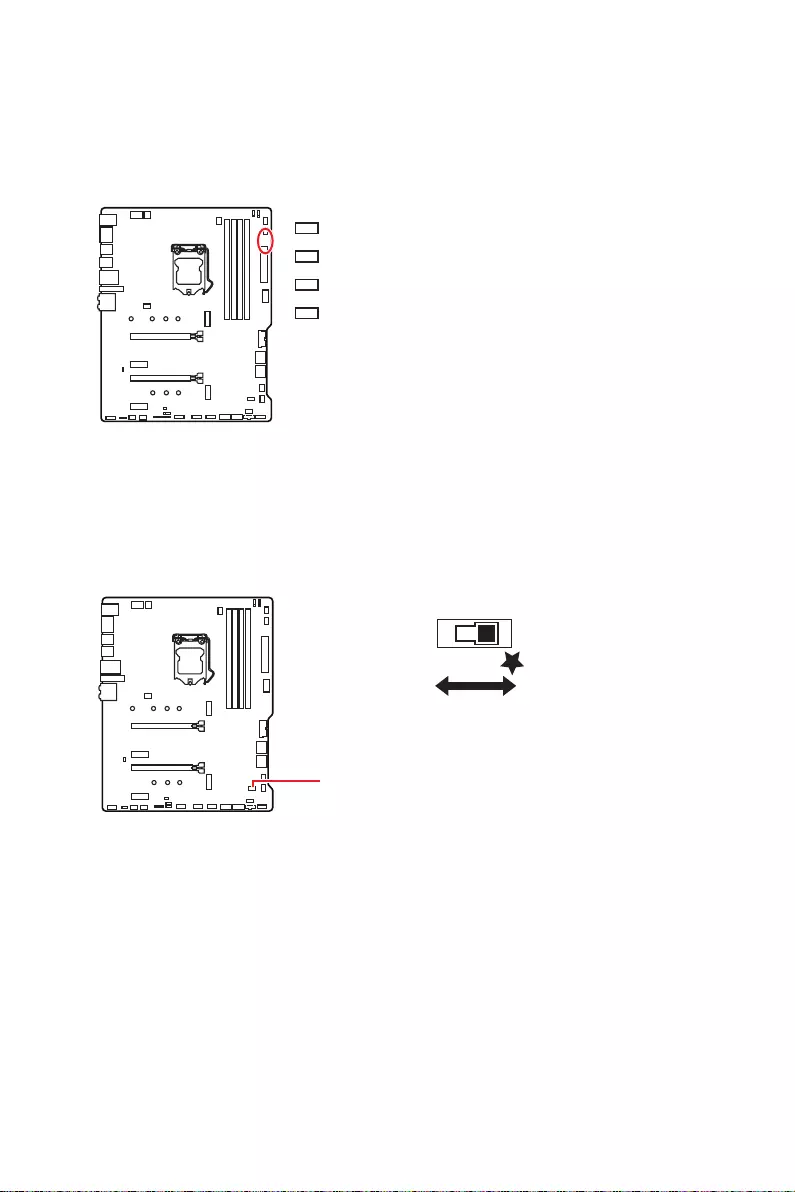
32 Onboard-LEDs
Onboard-LEDs
EZ Debug LED
Diese LEDs zeigen dtherboards an.
CPU
DRAM
VGA
BOOT
fehlerhaft.
LED_SW1: EZ LED—Steuerung
LED_SW1
LED_AUS LED_EIN
(Standard)

33
Installation von OS, Treibern und Utilities
Installation von OS, Treibern und Utilities
Laden Sie die neuesten Treiber und Dienstprogramme von www.msi.com herunter
und aktualisieren Sie sie
Installation von Windows® 10
1. Schalten Sie den Computer ein.
2. Legen Sie die Windows®
Laufwerk.
3. Drücken Sie die Taste Restart auf dem Computergehäuse.
4. Drücken Sie die F11
das Bootmenu zu öffnen.
5. Wählen Sie das optische Laufwerk aus dem Bootmenu.
6. Wenn eine entsprechende Meldung Press any key to boot from CD or DVD…
angezeigt wird, drücken Sie eine beliebige Taste.
7. Folgen Sie den Anweisungen auf dem Bildschirm, um das Dienstprogramm
„Windows® 10“ zu installieren.
Installation von Treibern
1. Starten Sie Ihren Computer mit Windows® 10.
2. Legen Sie die MSI® Treiber Disk in das optische Laufwerk.
3. Wählen Sie eine Aktion für Wechseldatenträger
aus und wählen Sie DVDSetup.exe starten aus, um den Installer zu öffnen. Wenn
können Sie das Programm DVD Setup.exe im Hauptverzeichnis der MSI Treiber CD
auch manuell ausführen.
4. Der Installer wird findet eine Liste aller benötigten Treiber auf der Treiber/
Software
5. Klicken Sie auf Install in der rechten unteren Ecke des Fensters.
6.
dazu aufgefordet, den Computer neu zu starten.
7. Klicken Sie zum Beenden auf OK.
8. Starten Sie Ihren Computer neu.
Installation von Utilities
beendet haben.
1. Öffnen Sie den Installer wie beschrieben.
2. Klicken Sie auf Utilities.
3. Wählen Sie die Dienstprogramme, die installiert werden soll.
4. Klicken Sie die Taste Install in der rechten unteren Ecke des Fensters.
5.
werden Sie dazu aufgefordet, den Computer neu zu starten.
6. Klicken Sie zum Beenden auf OK.
7. Starten Sie Ihren Computer neu.

34 UEFI BIOS
UEFI BIOS
basieren, werden zukünftig vollständig unterstützt.
⚠
Wichtig
sofern nicht anders angegeben.
Vorteile von UEFI
∙
Selbsttestprozess speichern. Außerdem entfällt die Zeit, um während des POST in den
∙Unterstützt Festplattenpartitionen, die größer als 2 TB sind.
∙
∙Unterstützt eine unbegrenzte Anzahl an Partitionen.
∙Unterstützt den vollen Funktionsumfang neuer Geräte – neue Geräte bieten
möglicherweise keine Abwärtskompatibilität.
∙Unterstützt sicheren Start – UEFI kann die Gültigkeit des Betriebssystems
überprüfen, um sicherzustellen, dass keine Malware den Startvorgang beeinträchtigt.
Inkompatible UEFI-Fälle
∙32-Bit-Windows-Betriebssystem
∙Ältere Grafikkarten — Das System erkennt Ihre Grafikkarte. Bei Erkennung einer
nicht kompatiblen Grafikkarte wird die Warnmeldung Auf dieser Grafikkarte wurde
keine GOP-Unterstützung (Graphics Output Protocol) erkannt“ erkannt.
⚠
Wichtig
CPU mit integrierter Grafikeinheit zu verwenden, um eine normale Funktion des
Systems zu gewährleisten.
Wie überprüfe ich den BIOS-Modus?
CPU Temperature:
MotherBoard Temperature:
VCore:
DDR Voltage:
BIOS Mode: UEFI
UEFI-Startmodus

35
UEFI BIOS
BIOS Setup
Die Standardeinstellungen bieten die optimale Leistung für die Systemstabilität unter
Normalbedingungen. Sie sollten immer die Standardeinstellungen behalten, um
ausreichende BIOS Kenntnisse.
⚠
Wichtig
∙
BIOS Funktionen werden für eine bessere Systemleistung kontinuierlich
aktualisiert. Deswegen können die Beschreibungen leicht von der letzten Fassung
des BIOS abweichen und sollten demnach nur als Anhaltspunkte dienen. Für eine
Beschreibung der BIOS Funktionen rufen Sie die HELP Informationstafel aus.
∙
Die Bilder in diesem Kapitel stellen lediglich Referenzen dar und können von dem
von Ihnen erworbenen Produkt abweichen.
∙
Öffnen des BIOS Setups
ENTF, wenn die Meldung Press
DEL key to enter Setup Menu, F11 to enter Boot Menu erscheint.
Funktionstasten
F1: Allgemeine Hilfe
F2: Hinzufügen/Entfernen eines Favoritenpunkts
F3: Öffnen des Favoriten Menüs
F4:
F5:
F6:
F7:
F8:
F9:
F10: *
F12: Macht .
Strg+F: Öffnet die Suchseite
* Beim Drücken der F10 Taste wird das Fenster zum Speichern der Einstellungen
angezeigt. Wählen Sie Yes, um die Wahl zu bestätigen, oder No, um die derzeitige
Einstellung beizubehalten.
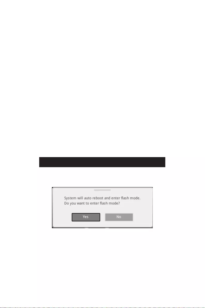
36 UEFI BIOS
Reset des BIOS
Sie können die Werkseinstellung wieder herstellen, um bestimmte Probleme zu
lösen. Es gibt verschiedene Möglichkeiten, um das BIOS zurückzusetzen:
∙Öffnen Sie das BIOS und drücken Sie F6, um optimierten Einstellungen zu laden.
∙Schließen Sie die Clear CMOS Steckbrücke an das Motherboard an.
⚠
Wichtig
„Clear CMOS
Steckbrücke
“ nach.
Aktualisierung des BIOS
Aktualisierung des BIOS mit dem M-FLASH-Programm
Vorbereitung:
1.
2.
▪Ctrl + F5 und
klicken Sie auf Yes (Ja), tum das System neu zu starten.
▪Beim Neustart drücken Sie Del (Entf)
. Klicken Sie die Taste M-FLASH und klicken
Sie auf Yes (Ja), tum das System neu zu starten.
3.
aus.
4. Klicken Sie auf Ja, wenn Sie dazu aufgefordert werden, um die Wiederherstellung
des BIOS zu starten.
5. Nachdem das Flashen des BIOS vollständig ist, startet das System automatisch
neu.
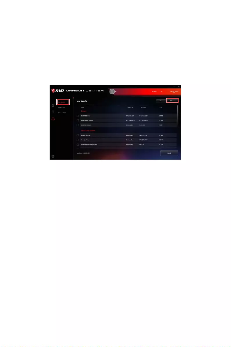
37
UEFI BIOS
Aktualisierung des BIOS mit MSI DRAGON CENTER
Vorbereitung:
Internetverbindung eingerichtet ist.
Schritte zur Aktualisierung des BIOS:
1. Installieren und starten Sie „MSI DRAGON CENTER“ und gehen Sie zur Support
Seite.
2. Wählen Sie Live Update aus und klicken Sie auf die Schaltfläche Advance.
3. Klicken Sie auf die Schaltfläche Scan
4. Download
5. Klicken Sie auf Next (Weiter) und wählen Sie In Windows Mode aus. Und klicken
dann auf Next (Weiter) und Start (Starten)
6. Nachdem das Flashen des BIOS vollständig ist, startet das System automatisch
neu.
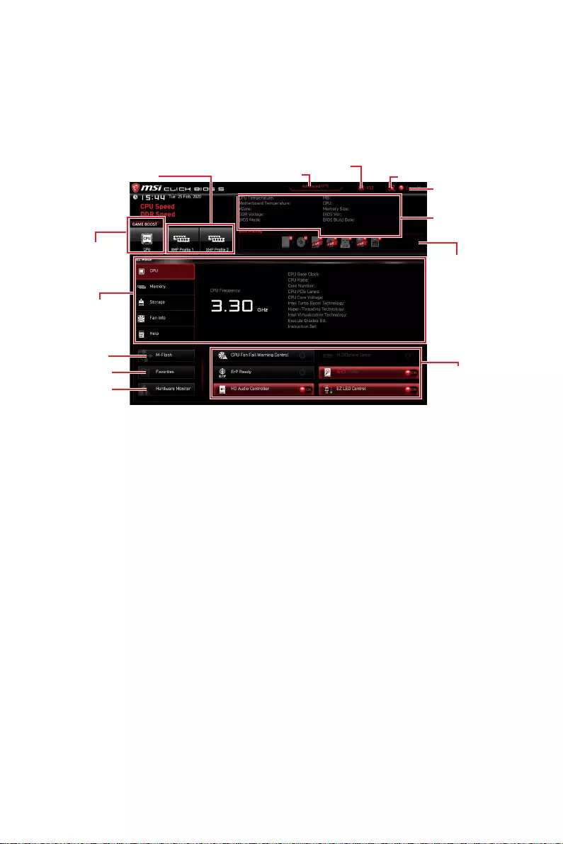
38 UEFI BIOS
EZ Modus
Einstellungen anzeigen zu lassen, aktivieren Sie bitte den Erweiterten Modus durch
Drücken des Setup Modus Schalter oder der Funktionstaste F7.
XMP Profil
information
information
Prioritätsleiste
tasten
Sprache
GAME BOOST
Suchen
Screenshot
Setup Modus Schalter
Hardware
Monitor
Favoriten
∙GAME BOOST
Diese Funktion kann nur dann genutzt werden, wenn sowohl das Motherboard als
auch die CPU diese Funktion unterstützen.
⚠
Wichtig
Bitte ändern Sie keine Werte im OC Menü und laden Sie keine Standardwerte während
GAME BOOST aktiviert ist, um die optimale Leistung und Stabilität des Systems zu
gewährleisten.
∙XMP Profil
Speicher übertaktet werden soll. Diese Funktion steht nur zur Verfügung, wenn das
∙Setup Modus SchalterF7
∙ScreenshotF12
∙SuchenStrg+F Taste um die
Suchseite anzuzeigen. Mit der Funktion können Sie durch Eingabe eines Suchbegriffs
und klicken Sie mit der rechten Maustaste, um die Suchseite zu schließen.
⚠
Wichtig
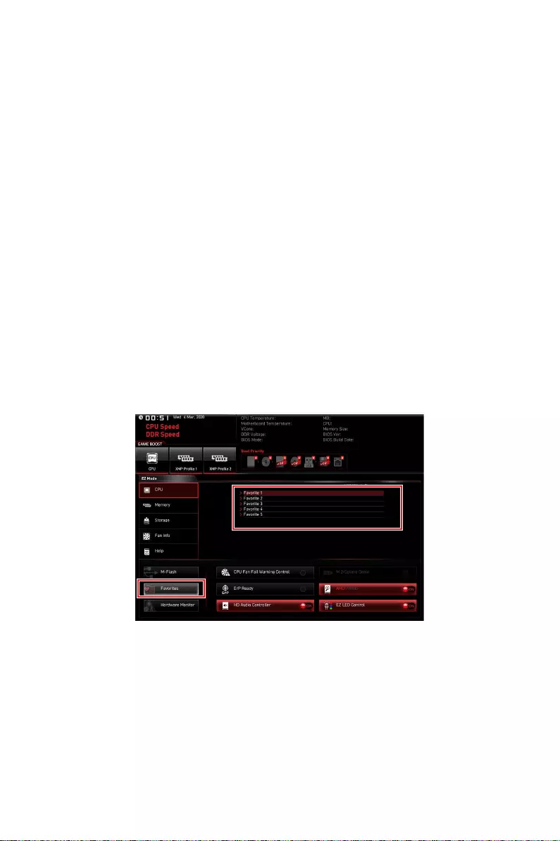
39
UEFI BIOS
∙Sprache
∙Systeminformationen
∙Boot-Geräte Prioritätsleiste
Startreihenfolge zu ändern. Die Bootreihenfolge sind mit “hoch”(links) bis “niedrig”
(rechts) bezeichnet.
∙Komponenteninformation CPU, Memory, Storage,
Fan Info und Help auf der linken Seite, um die Informationen der angeschlossenen
Komponente anzuzeigen.
∙Funktionstasten
Anklicken der Schaltfläche. Die Funktion ist aktiviert, wenn die Taste Auf EIN anzeigt.
⚠
Wichtig
Die Funktionstasten variieren je nach erworbenem Motherboard.
∙M-FlashM-Flash mit dem Sie das BIOS mit
∙Hardware Monitor Ein Klick auf diese Schaltfläche öffnet das Menü des Hardware
Monitor mit dem Sie die Lüfterdrehzahl in Prozent manuell steuern.
∙Favoriten F3, um das
Fenster Favoriten anzuzeigen. Es bietet fünf Menüs zum Erstellen eines persönlichen
speichern und darauf zugreifen können.
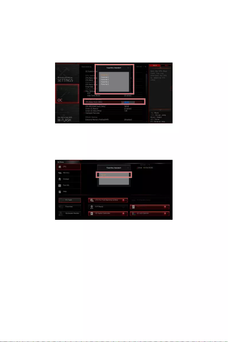
40 UEFI BIOS
▪Um ein BIOS-Punkte zu einer Favoritenmenü hinzufügen
1.
Suchseite auswählen.
2. Klicken Sie mit der rechten Maustaste oder drücken Sie die Taste F2.
3. Wählen Sie die gewünschte Seite aus und klicken Sie auf OK.
▪Um ein BIOS-Punkte von Favoritenmenü zu löschen
1.
2. Klicken Sie mit der rechten Maustaste oder drücken Sie die Taste F2.
3. Wählen Sie Delete aus und klicken Sie auf OK.
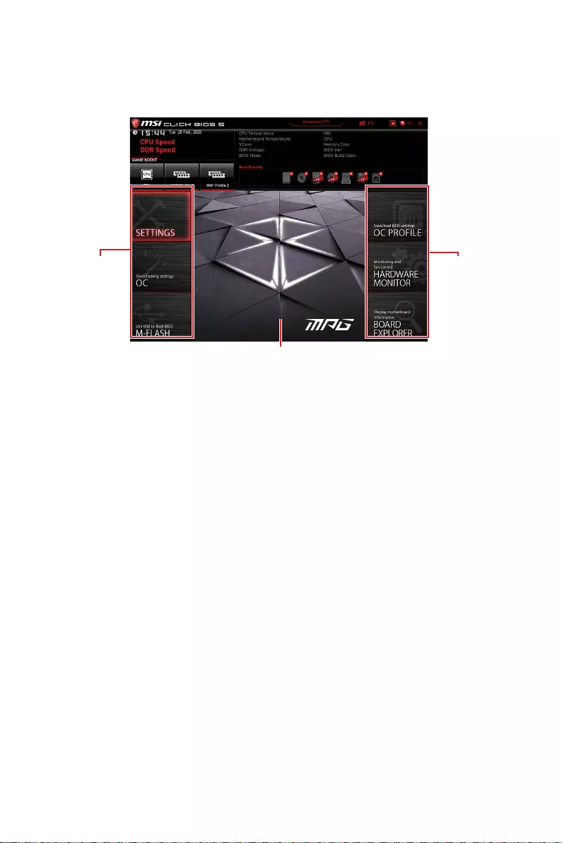
41
UEFI BIOS
Erweiterter Modus
Drücken Sie den Setup Modus Schalter oder die Funkionstaste F7, um zwischen dem
Menüanzeige
∙BIOS-Menü-Auswahl
▪SETTINGS
Geräte angeben.
▪OC
Frequenz kann eine bessere Leistung erreichen.
▪M-FLASH
aktualisieren.
▪OC PROFILE
gespeichert.
▪HARDWARE MONITOR
anpassen und die Spannungen des Systems überwachen.
▪BOARD EXPLORER
Mainboard angeschlossen sind.
∙Menüanzeige

42 UEFI BIOS
OC Menü
In diesem Menü können Sie die Frequenzen und Spannungen für das Übertakten
konfigurieren. Bitte beachten Sie, dass höhere Frequenzen und Spannungen die
Übertaktungsfähigkeit verbessern können, jedoch zu einer Instabilität des Systems
führen.
⚠
Wichtig
∙
Die Übertaktung ist nur für fortgeschrittene Benutzer zu empfehlen.
∙
Eine erfolgreiche Übertaktung ist nicht gewährleistet. Die Anwendung von
Übertaktungsmaßnahmen kann zu Verlust der Garantie oder zur Beschädigung der
Hardware führen.
∙
Falls Sie sich mit der Übertaktung nicht auskennen, empfehlen wir für einfaches
Übertakten die GAME BOOST Funktion.
∙
▶OC Explore Mode [Expert]
Aktivieren oder deaktivieren Sie die Funktion, um die normale oder Expertenversion
[Expert] Bietet die erweiterten Übertaktungseinstellungen für den erfahrenen
wollen.
Hinweis: Wir verwenden * als Symbol für die Übertaktungseinstellungen des
Erweiterten Modus.
▶CPU Ratio Apply Mode [All Core]*
nur, wenn eine CPU installiert ist, die die Funktion Turbo Boost unterstützt.
▶CPU Ratio [Auto]
Diese Option erscheint nur, wenn CPU Ratio Apply Mode auf All Core eingestellt.
▶X-Core Ratio Limit [Auto]
Hier können Sie die CPU Taktraten der verschiedenen aktiven Kerne anpassen. Diese
Option kann nur geändert werden, wenn CPU Ratio Apply Mode auf Turbo Ratio
eingestellt.
▶Numbers of CPU Cores of Group X [Auto]*
vorangegangene Gruppe haben. Diese Option kann nur geändert werden, wenn CPU
Ratio Apply Mode auf Turbo Ratio eingestellt.
▶Target CPU Turbo Ratio Group X [Auto]
Diese Option kann nur geändert
werden, wenn CPU Ratio Apply Mode auf Turbo Ratio eingestellt.

43
UEFI BIOS
▶Adjusted CPU Frequency
Zeigt die eingestellte Frequenz der CPU an. Es handelt sich um eine Anzeige –
▶Core X X of X xxxx MHz [Auto]
Hier können Sie die CPU Taktraten der verschiedenen aktiven Kerne anpassen. Diese
Optionen kann nur geändert werden, wenn CPU Ratio Apply Mode auf Per Core
eingestellt.
▶ Turbo Ratio Oset Value [Auto]
CPU
Ratio Apply Mode auf Turbo Ratio Offset eingestellt.
▶CPU Ratio Mode [Dynamic Mode]*
verändert.
▶ CPU Ratio Oset When Running AVX [Auto]
die Einstellung auf [Auto] gesetzt ist, wird das BIOS diese Einstellungen automatisch
Diese Option wird angezeigt, wenn die CPU diese Funktion unterstützt.
▶Ring Ratio [Auto]
Setzen Sie den Ring Ratio. Der erlaubte Wertebereich ist abhängig von der
installierten CPU.
▶Adjusted Ring Frequency
▶GT Ratio [Auto]
Setzen Sie den Multiplikator der integrierten Grafik. Der erlaubte Wertebereich ist
abhängig von der installierten CPU.
▶Adjusted GT Frequency
möglich.
▶+Misc Setting*
zu öffnen oder zu schließen.
▶CPU Base Clock (MHz) [Default]
Hier können Sie den CPU Grundtakt anpassen. Sie können die CPU übertakten,
indem Sie diesen Wert verändern. Bitte beachten Sie, dass die Übertaktung (und das
Ergebnis) und die Stabilität nicht gewährleistet sind. Diese Option wird angezeigt,
wenn der installierte Prozessor diese Funktion unterstützt.

44 UEFI BIOS
▶CPU Base Clock Apply Mode [Auto]*
Einstellung des angepassten CPU Grundtakts.
[Auto] Diese Einstellungen werden vom BIOS automatisch konfiguriert.
[Next Boot] Die CPU arbeitet mit angepasstem CPU Grundtakt nach einem
Neustart.
[Immediate] Die CPU arbeitet mit angepasstem CPU Grundtakt sofort.
▶Clockgen Features sub-menu
Drücken Sie die Eingabetaste <Enter>, um das Untermenü aufzurufen. Steuert die
▶ Extreme Memory Prole (XMP) [Disabled]
Extreme Memory Profile (XMP) basieren auf Zertifizierungen für Speichermodule
Speichermoduls zum Übertakten aus. Diese Option steht zur Verfügung, wenn die
installierten Speichermodule die XMP Technik unterstützen.
▶DRAM Reference Clock [Auto]*
der installierten CPU. Diese Option wird angezeigt, wenn die installierte CPU diese
Einstellungen unterstützt.
▶DRAM Frequency [Auto]
Setzen Sie die DRAM Frequenz. Bitte beachten Sie, dass ein zuverlässiges
Übertaktungsverhalten nicht garantiert werden kann.
▶Adjusted DRAM Frequency
▶Load Memory Presets [Disabled]*
Spannung und Timing), um die installierten Speicherleistung von BIOS zu optimieren.
▶Memory Try It ! [Disabled]
Die Option „Memory Try It!“ dient der Verbesserung der Speicherkompatibilität
Voreinstellungen.
▶DRAM Timing Mode [Link]
Speicherkanäle.
einzelnen Speicherkanäle.
▶ Advanced DRAM Conguration
Drücken Sie die Eingabetaste <Enter>, um das Untermenü aufzurufen. Der Anwender
die Standardeinstellungen wieder her. (Lesen Sie bitte den Abschnitt „Steckbrücke
Standardeinstellungen auf das BIOS zu laden.)

45
UEFI BIOS
▶Memory Fast Boot [Auto] *
Aktivieren oder deaktivieren Sie die die Initiierung und Prüfung des Speichers für
jeden Boot.
[Auto] Diese Einstellungen werden vom BIOS automatisch konfiguriert.
[Enabled] Der Vorgang der Initierung und Prüfung des Hauptspeichers wird
aus dem Archiv der ersten Initiierung imitiert um den Systemstart zu
beschleunigen.
geprüft.
▶DigitALL Power sub-menu
Drücken Sie die Eingabetaste <Enter>, um das Untermenü aufzurufen. Im Untermenü
können Sie einige Schutzbedingungen über Spannung/ Strom/ Temperatur für die
CPU. einstellen.
▶CPU Core/ GT Voltage Mode [Auto]*
Stellen Sie die Betriebmodi für diese CPU Core/ GT.
▶CPU Core Voltage Mode [Auto]*
Stellen Sie den Modus der CPU Core.
▶CPU Voltages control [Auto]
Auto gesetzt
ist, wird das BIOS die Spannungen automatisch einstellen oder Sie können es manuell
einstellen.
▶DRAM Voltages control [Auto]
Auto gesetzt
ist, wird das BIOS die Spannungen automatisch einstellen oder Sie können es manuell
einstellen.
▶PCH Voltages control [Auto]
Auto gesetzt
ist, wird das BIOS die Spannungen automatisch einstellen oder Sie können es manuell
einstellen.
▶CPU Memory Changed Detect [Enabled]*
Aktiviert/Deaktiviert die Systemwarnmeldung beim Booten, wenn die CPU oder der
Hauptspeicher ersetzt wurde.
[Enabled] Das System zeigt eine Warnmeldung beim Systemstart und lädt die
Einstellungen.
▶OC Quick View Timer [3 Sec]*
Einstellung auf Deaktiviert
Einstellungen nicht anzeigen.

46 UEFI BIOS
▶ CPU Specications sub-menu
Drücken Sie die Eingabetaste <Enter>, um das Untermenü aufzurufen. Das Drücken
Sie die Eingabetaste <Enter>, um das Untermenü aufzurufen. Das Untermenü zeigt
die Informationen der installierten CPU an. Zu diesen Informationen gelangen Sie,
indem Sie die Taste [F4] drücken. Nur Anzeige.
▶MEMORY-Z sub-menu
Drücken Sie die Eingabetaste <Enter>, um das Untermenü aufzurufen. Dieses
Untermenü zeigt alle Einstellungen und Timings des installierten Speichers. Zu
diesen Informationen gelangen Sie auch, indem Sie die Taste [F5] drücken.
▶CPU Features sub-menu
Drücken Sie die Eingabetaste <Enter>, um das Untermenü aufzurufen. Sie können
schützen und die Systemleistung zu verbessern.

1
Table des matières
Table des matières
Informations de sécurité …………………………………………………………………………… 3
Spécifications …………………………………………………………………………………………… 4
Contenu …………………………………………………………………………………………………. 10
Panneau arrière Entrée / Sortie ………………………………………………………………. 11
Tableau explicatif de l’état de la LED du port LAN ………………………………………. 11
Configuration des ports audio …………………………………………………………………… 11
Realtek Audio Console …………………………………………………………………………….. 12
Vue d’ensemble des composants …………………………………………………………….. 15
Socket processeur …………………………………………………………………………………… 16
Slots DIMM …………………………………………………………………………………………….. 17
PCI_E1~4 : Slots d’extension PCIe …………………………………………………………….. 18
CPU_PWR1, ATX_PWR1 : Connecteurs d’alimentation ………………………………… 19
JFP1, JFP2 : Connecteurs de panneau avant ……………………………………………… 20
JAUD1 : Connecteur audio avant ……………………………………………………………….. 20
M2_1~2 : Slots M.2 (Touche M) …………………………………………………………………. 21
SATA1~6 : Connecteurs SATA 6Gb/s …………………………………………………………. 23
CPU_FAN1, PUMP_FAN1, SYS_FAN1~6 : Connecteurs pour ventilateurs ……… 24
JUSB1~2 : Connecteurs USB 2.0 ………………………………………………………………. 25
JUSB4 : Connecteur USB 3.2 Gen 1 ………………………………………………………….. 25
JUSB3 : Connecteur USB 3.2 Gen 1 ………………………………………………………….. 26
JTBT1 : Connecteur de carte additionnelle Thunderbolt ……………………………… 27
JRTD3 : Connecteur Intel RTD3 ………………………………………………………………… 27
JBAT1 : Cavalier Clear CMOS (Réinitialisation BIOS) …………………………………… 28
JTPM1 : Connecteur de module TPM …………………………………………………………. 28
JCI1 : Connecteur intrusion châssis ………………………………………………………….. 29
JRGB1~2 : Connecteurs LED RGB …………………………………………………………….. 30
JRAINBOW1~2 : Connecteurs LED RGB addressables ………………………………… 31
Indicateurs LED embarqués ……………………………………………………………………. 32
EZ Debug LED …………………………………………………………………………………………. 32
LED_SW1 : Contrôle EZ LED …………………………………………………………………….. 32
Installer OS, Pilotes et Utilitaires …………………………………………………………….. 33
Installer Windows® 10 ……………………………………………………………………………… 33
Installer les pilotes ………………………………………………………………………………….. 33
Installer les utilitaires ……………………………………………………………………………… 33
UEFI BIOS ………………………………………………………………………………………………. 34

2Table des matières
Configuration du BIOS …………………………………………………………………………….. 35
Entrer dans l’interface Setup du BIOS ……………………………………………………….. 35
Réinitialiser le BIOS…………………………………………………………………………………. 36
Mettre le BIOS à jour ……………………………………………………………………………….. 36
EZ Mode …………………………………………………………………………………………………. 38
Advanced Mode (mode avancé) …………………………………………………………………. 41
OC Menu (menu overclocking) ………………………………………………………………….. 42

3
Informations de sécurité
Informations de sécurité
∙Les composants dans l’emballage peuvent être endommagés par des décharges
électrostatiques (ESD). Pour vous assurer de correctement monter votre ordinateur,
∙
connexion, il se peut que l’ordinateur ne reconnaisse pas le composant et que le
démarrage échoue.
∙Veuillez tenir la carte mère par les bords pour éviter de toucher les composants
sensibles.
∙Il est recommandé de porter un bracelet antistatique lors de la manipulation de la
carte mère pour prévenir tout dommage. Si vous n’avez pas de bracelet antistatique,
touchez un objet métallique relié à la terre avant de manipuler la carte mère afin de
vous décharger de votre charge statique. Touchez régulièrement l’objet métallique
pendant toute la manipulation.
∙
contre les ondes électrostatiques ou sur une couche antistatique.
∙Avant de démarrer l’ordinateur, vérifiez si toutes les vis et les composants
métalliques sont bien fixés sur la carte mère ou ailleurs dans le boîtier de l’ordinateur.
∙Ne démarrez pas l’ordinateur avant d’avoir terminé l’installation. Ceci peut
endommager les composants ou vous blesser.
∙Si vous avez besoin d’aide pendant l’installation, veuillez consulter un technicien
informatique certifié.
∙Avant d’installer les composants d’ordinateur, veuillez toujours mettre hors tension
et débrancher le cordon d’alimentation.
∙Gardez ce manuel pour références futures.
∙Protégez ce manuel contre l’humidité.
∙Avant de brancher le bloc d’alimentation sur la sortie électrique, veuillez
vous assurer que la tension de la sortie électrique est bien égale à celle du bloc
d’alimentation.
∙Placez le cordon d’alimentation de façon à éviter que l’on marche dessus. Ne posez
rien sur le cordon d’alimentation.
∙Veuillez prêter attention à toutes les alertes et remarques indiquées sur la carte
mère.
∙
carte mère :
▪Un liquide a pénétré dans l’ordinateur.
▪La carte mère a été exposée à de l’humidité.
▪La carte mère ne fonctionne pas comme indiqué dans les instructions.
▪La carte mère est tombée par terre et a été endommagée.
▪La carte mère est cassée.
∙Ne pas mettre la carte mère dans un environnement dont la température est
supérieure à 60° C (140° F) sous peine de l’endommager.

4Spécifications
Spécifications
CPU
Support des processeurs Intel® Core™ de 10ème
génération et Pentium® Gold / Celeron® pour socket LGA
1200*
* Veuillez vous au site www.intel.com pour plus d’informations de compatibilité.
* Les sorties vidéo intégrées sont indisponibles lors de l’utilisation des
processeurs série F.
Chipset Chipset Intel® Z490
Mémoire
∙4 x slots pour mémoire DDR4, support jusqu’à 128Go*
∙Support 1R 2133 / 2666 / 2933 MHz*
▪La fréquence maximale en mode 1DPC 1R jusqu’à
4800+ MHz
▪La fréquence maximale en mode 1DPC 2R jusqu’à
4266+ MHz
▪La fréquence maximale en mode 2DPC 1R jusqu’à
4400+ MHz
▪La fréquence maximale en mode 2DPC 2R jusqu’à
4000+ MHz
∙Support mode double canal
∙mémoire
∙Support Intel® Extreme Memory Profile (XMP)
* Veuillez vous référer au site www.msi.com pour plus d’informations sur la
mémoire compatible.
Slots d’extension
∙1 x slot PCIe 3.0 x 16 (du CPU)
∙1 x slot PCIe 3.0 x 16 (mode x 4, du PCH)
∙2 x slots PCIe x 1 (du PCH)
* Veuillez vous référer à la page 17 pour le tableau de la bande passante du
PCIe 3.0.
Sorties vidéo
intégrées
∙1 x port HDMI, supportant une résolution maximum de
4096 x 2160 @ 30Hz
∙1 x port DisplayPort supportant une résolution maximum
de 4096 x 2304 @ 60Hz
Multi-GPU ∙
Suite du tableau sur la page suivante

5
Spécifications
Suite du tableau sur la page précédente
Stockage
Chipset Intel® Z490
∙6 x ports SATA 6Gb/s*
∙2 x slots M.2 (Touche M)
▪Support jusqu’à PCIe 3.0 x 4 et SATA 6Gb/s
▪Le slot M2_1 supporte des périphériques de stockage
2242 / 2260 / 2280 / 22110*
▪Le slot M2_2 supporte des périphériques de stockage
2242 / 2260 / 2280**
▪Intel® Optane™ Memory Ready***
* Le connecteur SATA2 est indisponible lorsqu’un SSD SATA M.2 est installé
dans le slot M2_1.
** Les connecteurs SATA5 et SATA6 sont indisponibles lorsqu’un SSD SATA /
PCIe M.2 est installé dans le slot M2_2.
*** Avant d’utiliser les modules de mémoire Intel® Optane™, veuillez vous
assurer d’avoir mis à jour les pilotes et le BIOS avec la dernière version
disponible sur le site officiel MSI.
RAID
Chipset Intel® Z490
∙Support RAID 0, RAID1, RAID 5 et RAID 10 pour les
périphériques de stockage SATA
∙Support RAID 0 et RAID 1 pour les périphériques de
stockage M.2 PCIe
LAN 1 x contrôleur
USB
∙Chipset Intel® Z490
▪sur le panneau
arrière
▪sur
le panneau arrière, 2 ports par l’intermédiaire des
connecteurs USB internes, 1 )
▪2 x ports USB 2.0 sur le panneau arrière
▪4 x ports USB 2.0 disponibles par l’intermédiaire des
connecteurs USB interne
∙ASMedia® ASM3241
▪sur le
panneau arrière
Audio
∙Audio haute définition 7,1
∙Support sortie S / PDIF
Suite du tableau sur la page suivante

6Spécifications
Suite du tableau sur la page précédente
Wireless / Bluetooth
Intel® AX201
∙ jusqu’à
2.4Gbps
∙
∙Bluetooth 5.1, FIPS, FISMA
∙
Connecteurs sur le
panneau arrière
∙1 x port combo souris / clavier PS/2
∙2 x ports USB 2.0
∙1 x DisplayPort
∙1 x port HDMI
∙
∙
∙1 x port LAN (RJ45)
∙
∙
∙1 x connecteur Sortie S / PDIF optique
∙5 x jacks audio
Connecteurs
internes
∙1 x connecteur d’alimentation principal ATX à 24 broches
∙1 x connecteur d’alimentation ATX 12V à 8 broches
∙1 x connecteur d’alimentation ATX 12V à 4 broches
∙6 x connecteurs SATA 6 Gb/s
∙
∙1 x connecteur USB 3.2 Gen 1 5Gbps (support de 2 autres
ports USB 3.2 Gen 1 5Gbps)
∙2 x connecteurs USB 2.0 (support de 4 autres ports USB
2.0)
∙1 x connecteur de ventilateur CPU à 4 broches
∙1 x connecteur de ventilateur à 4 broches pour la pompe
à eau
∙6 x connecteurs de ventilateur système à 4 broches
∙1 x connecteur audio avant
∙2 x connecteurs de panneau système
∙1 x connecteur intrusion châssis
Suite du tableau sur la page suivante

7
Spécifications
Suite du tableau sur la page précédente
Connecteurs
internes
∙1 x cavalier Clear CMOS
∙2 x connecteurs LED RGB à 4 broches
∙2 x connecteurs de LED RAINBOW à 3 broches
∙1 x connecteur de module TPM
∙1 x connecteur TBT*
∙1 x connecteur RTD3
* La carte Thunderbolt doit prendre en charge RTD3
Fonctions LED ∙1 x interrupteur de commande LED
∙4 x EZ Debug LED
Contrôleur E / S Contrôleur NUVOTON NCT6687
Moniteur système
∙Détection de la température du CPU et du système
∙Détection de la vitesse du ventilateur du CPU et du
système
∙Contrôle de la vitesse du ventilateur du CPU et du
système
Dimensions ∙Format ATX
∙30,5 cm x 24,4 cm (12” x 9,6”)
Fonctions BIOS
∙1 x flash 256 Mb
∙UEFI AMI BIOS
∙ACPI 6.2, SM BIOS 3.2
∙Multilingue
Logiciel
∙Pilotes
∙DRAGON CENTER
∙Intel Extreme Tuning Utility
∙MSI App Player (BlueStacks)
∙Open Broadcaster Software (OBS)
∙
∙Google Chrome™, Google Toolbar, Google Drive
∙Norton™ Internet Security Solution
Suite du tableau sur la page suivante

8Spécifications
Suite du tableau sur la page précédente
Fonctions Dragon
Center
∙Gaming Mode
∙Gaming Hotkey
∙LAN Manager
∙Mystic Light
∙Ambient Link
∙User Scenario
∙Monitor(Hardware
Monitor)
∙True Color
∙Live Update
∙DPC Latency tuner
∙Speed Up
∙Smart Tool
∙Super Charger
download.msi.com/manual/mb/
DRAGONCENTER2.pdf pour plus de
détails.
Fonctions spéciales
∙Audio
▪Audio Boost
∙Network
▪2.5G LAN
▪LAN Manager
▪Intel WiFi
∙Cooling
▪Extended Heatsink Design
▪M.2 Shield Frozr
▪Pump Fan
▪Smart Fan Control
∙LED
▪Mystic Light
▪Mystic Light Extension (RGB)
▪Mystic Light Extension (RAINBOW)
▪Mystic Light Sync
▪EZ DEBUG LED
▪EZ LED Control
Suite du tableau sur la page suivante

9
Spécifications
Suite du tableau sur la page précédente
Fonctions spéciales
∙Protection
▪PCIe Steel Armor
▪
∙Performance
▪
▪DDR4 Boost
▪Core Boost
▪GAME Boost
▪Lightning USB 20G
▪USB 3.2 Gen 2 10G
▪USB avec type A+C
▪
▪Dual CPU Power
∙Experience
▪DRAGON CENTER
▪Click BIOS 5
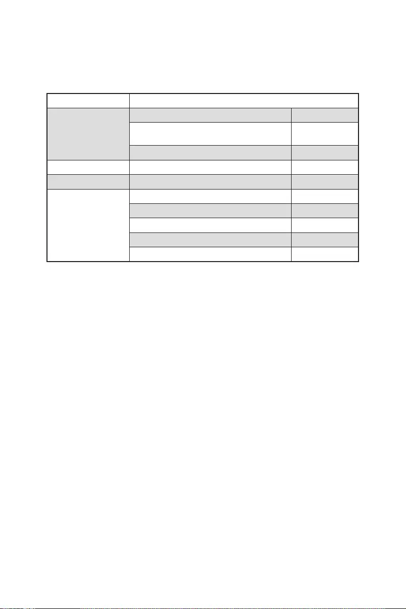
10 Contenu
Contenu
Vérifiez tous les articles dans le carton d’emballage de votre carte mère. L’emballage
doit contenir :
Carte mère MPG Z490 GAMING EDGE WIFI
Documentation
Manuel d’utilisation 1
Avertissement pour l’installation des
entretoises 1
Guide d’installation rapide 1
Application DVD de pilotes 1
Câbles Câble SATA 6G (2 câbles / paquet) 1
Accessoires
1
Insigne pour châssis 1
Etiquettes pour câbles SATA 1
Carte d’enregistrement de produit 1
Vis M.2 (3 pièces / sac) 1
⚠
Important
ou manquant.
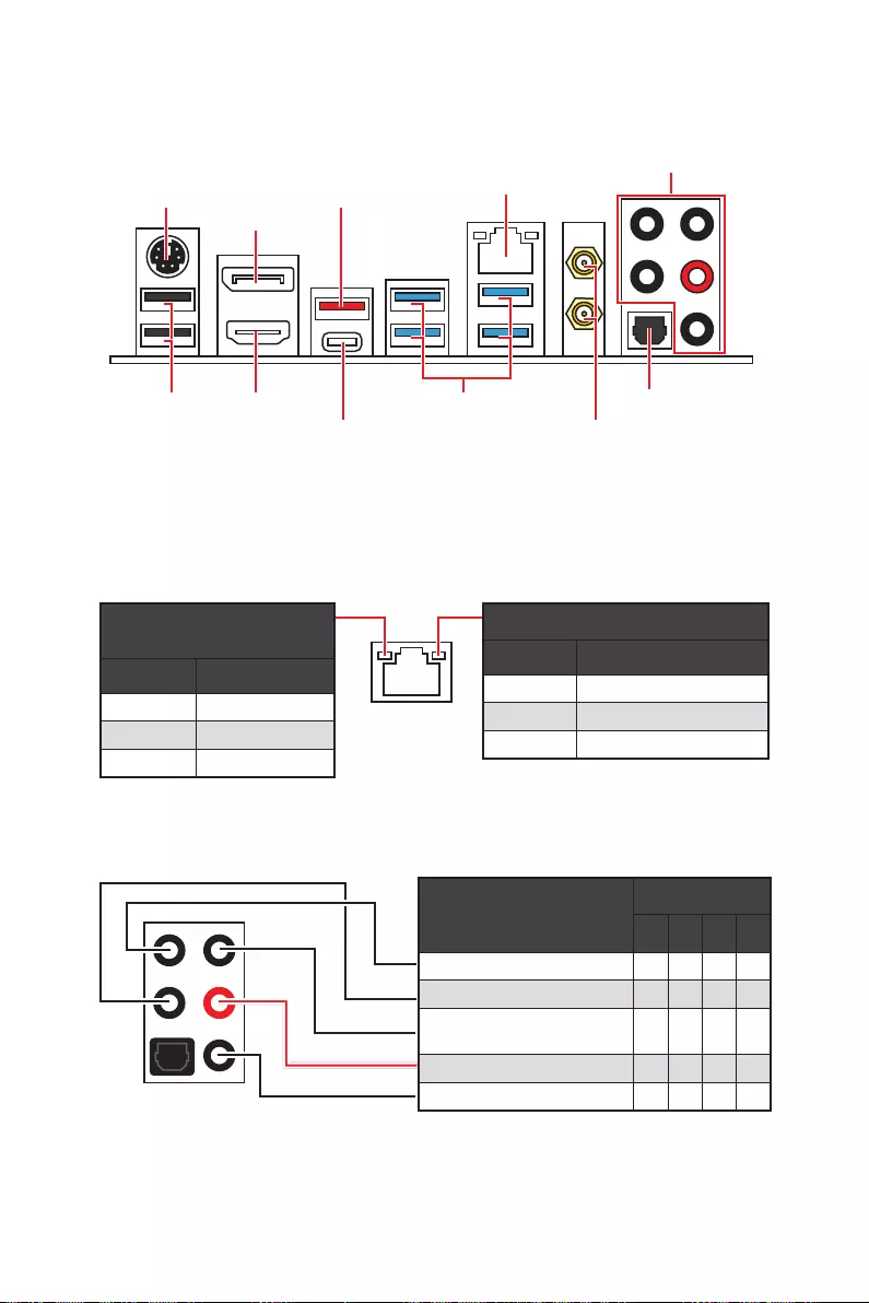
11
Panneau arrière Entrée / Sortie
Panneau arrière Entrée / Sortie
Ports Audio
Sortie S / PDIF optique
Connecteur d’antenne
PS/2
port HDMI
DisplayPort
USB 2.0
2.5Gbps LAN
USB 3.2 Gen 2 10Gbps
USB 3.2 Gen 1 5Gbps
USB 3.2 Gen 2×2 20Gbps
Configuration des ports audio
LED indiquant la connexion
et l’activité
Etat Description
Eteint Pas de connexion
Jaune Connexion correcte
Clignote Activité en cours
LED indiquant la vitesse
Etat Description
Eteint Débit de 10 Mbps
Vert Débit de100 Mbps / 1 Gbps
Orange Débit de 2.5 Gbps
Tableau explicatif de l’état de la LED du port LAN
Ports Audio Canal
2468
Sortie centre / Caisson de basse
parleur côté
Sortie Ligne / Sortie casque avant
Entrée Microphone
(: connecté, Espace : vide)
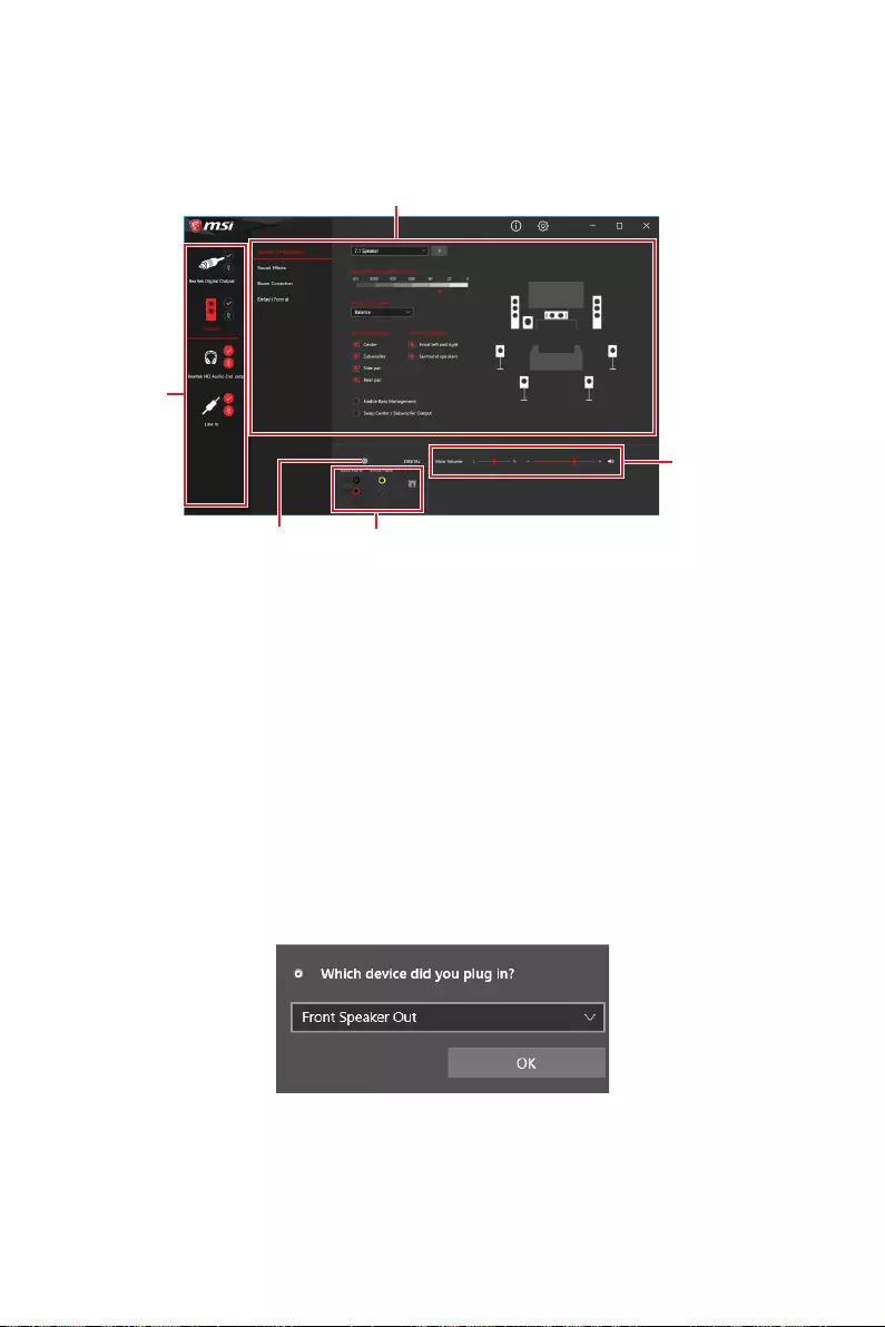
12 Contenu
Realtek Audio Console
Après l’installation de Realtek Audio Console, vous pouvez l’utiliser pour modifier les
paramètres du son afin d’obtenir une meilleure expérience sonore.
∙Sélection du périphérique
audio pour en modifier les paramètres. Le symbole de coche indique le périphérique
sélectionné par défaut.
∙Amélioration d’application
des effets acoustiques proposés pour les périphériques de sortie et d’entrée.
∙Volume principal
parleurs branchés sur le panneau avant ou derrière en ajustant la barre de volume.
∙Etat des prises Jack
connectés à votre ordinateur.
∙Paramètres du connecteur
Dialogue popup automatique
Lorsqu’un périphérique est branché sur une prise audio, une fenêtre de dialogue
apparaîtet vous demande de choisir le périphérique connecté que vous souhaitez
utiliser.
Chaque jack est réglé avec ses paramètres par défaut comme indiqué sur la page
suivante.
⚠
Important
le produit que vous achetez.
Etat des prises Jack
Paramètres du connecteur
Sélection du
périphérique
Volume principal
Amélioration d’application

13
Contenu
Illustration de l’utilisation des ports audio dédiés au casque et au
microphone
Illustration de l’utilisation du port audio dédié aux haut-parleurs
Illustration de l’utilisation des ports audio dédiés aux haut-parleurs 7.1
AUDIO INPUT
AUDIO INPUT
Rear Front
Side Center/
Subwoofer

14 Contenu
Installation des antennes
1. Vissez fermement les antennes aux connecteurs dédiés, comme illustré ici.
2. Orientez les antennes.
1
2
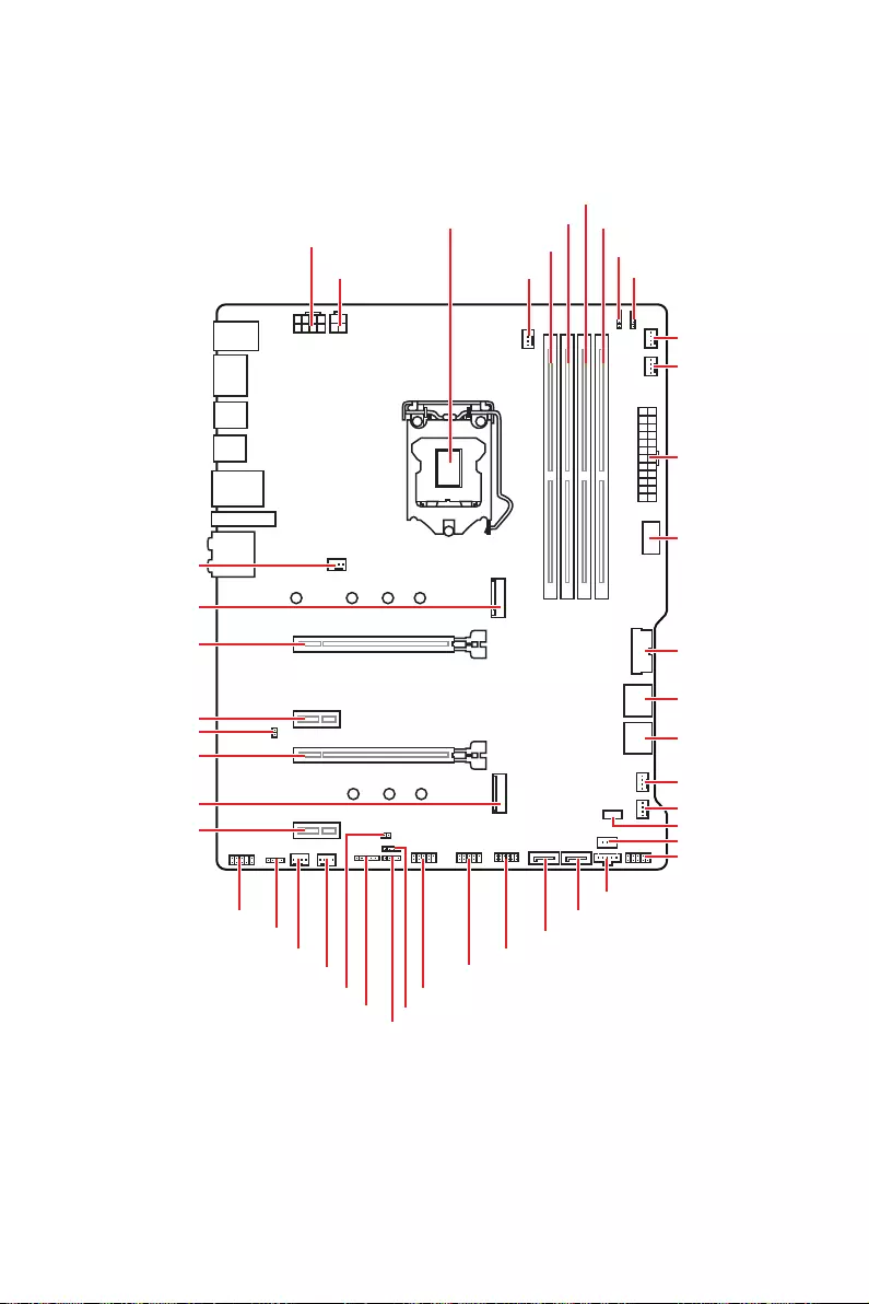
15
Vue d’ensemble des composants
Vue d’ensemble des composants
DIMMA1
CPU_FAN1
DIMMA2
DIMMB1
DIMMB2
JRGB2
JRAINBOW2
PUMP_FAN1
SYS_FAN6
SYS_FAN5
SYS_FAN1
SYS_FAN4
LED_SW1
JRTD3
JFP1
JTBT1
SATA6
SATA5
JTPM1
JUSB1
JUSB2
JFP2
JT1
JBAT1
JRAINBOW1
ATX_PWR1
JUSB4
JUSB3
Socket
processeur
CPU_PWR1
CPU_PWR2
SYS_FAN3
SYS_FAN2
JRGB1
JAUD1
PCI_E4
PCI_E3
M2_2
M2_1
JCI1
PCI_E2
PCI_E1

16 Vue d’ensemble des composants
⚠
Important
∙
Avant d’installer ou de retirer le processeur du socket, veillez à toujours débrancher
le câble d’alimentation de la prise électrique.
∙
Veuillez garder le capot de protection du processeur après l’installation du
processeur. Selon les exigences de RMA (Return Merchandise Authorization), MSI
n’acceptera pas les cartes mère dont le capot de protection aura été retiré.
∙
Lors de l’installation d’un processeur, n’oubliez pas d’installer un ventilateur pour
processeur. Un ventilateur de processeur est nécessaire pour protéger le processeur
contre la surchauffe et maintenir la stabilité du système.
∙
démarrer votre système.
∙
La surchauffe peut facilement endommager le processeur et la carte mère.
de pâte thermique (ou adhésif thermique) entre le processeur et le système de
refroidissement afin d’améliorer la dissipation de la chaleur.
∙
Quand le processeur n’est pas installé, protégez toujours les broches de
l’emplacement du processeur avec le couvercle dédié.
∙
Si vous avez achetez un processeur indépendamment du ventilateur, veuillez vous
référer à la documentation dans le paquet du ventilateur pour plus d’informations
concernant l’installation.
∙
Cette carte mère supporte l’overclocking. Néanmoins, veuillez vous assurer que vos
composants soient capables de tolérer l’overclocking. Prenez note que l’utilisation
pas les dommages et risques causés par les utilisations non prévues dans les
spécifications du produit.
Socket processeur
Présentation du socket LGA 1200
Sur le socket LGA 1200, vous
remarquerez deux encoches et un
triangle doré servant d’indicateurs pour
placer le processeur dans la bonne
position. Le triangle doré correspond à
la broche 1 du processeur.
50.6 mm
Distance entre le centre du CPU
et le slot DIMM le plus proche.

17
Vue d’ensemble des composants
Slots DIMM
DIMMA1 DIMMB1
Canal A Canal B
DIMMA2 DIMMB2
Installation recommandée de module mémoire
⚠
Important
∙
Veillez à toujours insérer un module de mémoire dans l’emplacement DIMMA2 en
premier.
∙
d’installer les modules de mémoire du même type, du même nombre et de la même
densité.
∙
Certaines mémoires peuvent fonctionner à une fréquence réduite par rapport à
la valeur indiquée lors de l’overclocking car la fréquence d’opération de mémoire
fonction DRAM Frequency pour régler la fréquence de mémoire si vous voulez faire
fonctionner la mémoire à la fréquence indiquée ou à une fréquence plus élevée.
∙
Il est recommandé d’utiliser un système de refroidissement qui sera capable de
refroidir toutes les barrettes mémoire et d’offrir de bonnes performances lors d’un
overclocking.
∙
La stabilité et la compatibilité du module de mémoire lors de l’overclocking
dépendent du processeur et des périphériques installés.
∙
Veuillez vous référer au site www.msi.com pour plus d’informations sur la mémoire
compatible.
DIMMB2 DIMMB2
DIMMB1
DIMMA2 DIMMA2 DIMMA2
DIMMA1

18 Vue d’ensemble des composants
PCI_E1~4 : Slots d’extension PCIe
⚠
Important
∙
Si vous installez une carte graphique lourde, il vous faut utiliser un outil comme
la barre de support MSI Gaming Series pour supporter son poids et pour éviter la
déformation du slot.
∙
Si vous choisissez d’installer une seule carte d’extension PCIe x 16, nous vous
recommandons d’utiliser le slot PCI_E1 pour profiter de performances optimales.
∙
Veillez à toujours mettre l’ordinateur hors tension et à débrancher le cordon
documentation des cartes pour vérifier si un composant ou un logiciel doit être
modifié.
PCI_E1 : PCIe 3.0 x 16 (CPU)
PCI_E3 : PCIe 3.0 x 4 (PCH)
PCI_E2 : PCIe 3.0 x 1 (PCH)
PCI_E4 : PCIe 3.0 x 1 (PCH)

19
Vue d’ensemble des composants
24
131
12
ATX_PWR1
1 +3.3V 13 +3.3V
2 +3.3V 14
3 Ground 15 Ground
4 +5V 16
5 Ground 17 Ground
6 +5V 18 Ground
7 Ground 19 Ground
8 PWR OK 20 Res
9 5VSB 21 +5V
10 +12V 22 +5V
11 +12V 23 +5V
12 +3.3V 24 Ground
5
4 1
8CPU_PWR1
1 Ground 5 +12V
2 Ground 6 +12V
3 Ground 7 +12V
4 Ground 8 +12V
⚠
Important
Veuillez vous assurer que tous les câbles d’alimentation sont branchés aux
connecteurs adéquats afin garantir une opération stable de la carte mère.
CPU_PWR1, ATX_PWR1 : Connecteurs d’alimentation
Ces connecteurs vous permettent de relier une alimentation ATX.
3
2 1
4CPU_PWR2
1 Ground 3 +12V
2 Ground 4 +12V

20 Vue d’ensemble des composants
JFP1, JFP2 : Connecteurs de panneau avant
Ces connecteurs se lient aux interrupteurs et indicateurs LED du panneau avant.
1
2 10
9
+
+
+
+
Power LED
HDD LED Reset Switch
Reserved
Power Switch
JFP1
1 HDD LED + 2 Power LED +
3 4
5 Reset Switch 6 Power Switch
7 Reset Switch 8 Power Switch
9 Reserved 10 No Pin
1
JFP2
+
+
Speaker
Buzzer 1 2 Buzzer +
3 4 Speaker +
JAUD1 : Connecteur audio avant
Ce connecteur se lie aux jacks audio du panneau avant.
1
2 10
9
1 MIC L 2 Ground
3 MIC R 4 NC
5 Head Phone R 6 MIC Detection
7 SENSE_SEND 8 No Pin
9 Head Phone L 10 Head Phone Detection
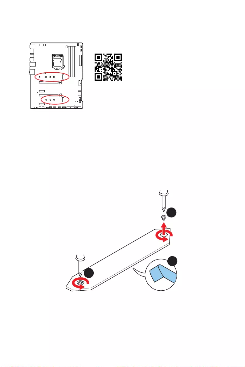
21
Vue d’ensemble des composants
M2_1~2 : Slots M.2 (Touche M)
⚠
Important
∙
La technologie Intel® RST supporte seulement un SSD M.2 PCIe avec une mémoire
ROM UEFI.
∙
Intel® Optane™ Memory Ready pour le slot M.2.
⚽
Vidéo de démonstration
module M.2.
1
1
2
Installation du module M.2
1. Desserrez la vis de la plaque M.2 SHIELD FROZR.
2. Retirez la plaque M.2 SHIELD FROZR et retirez le film de protection du pad
thermique.
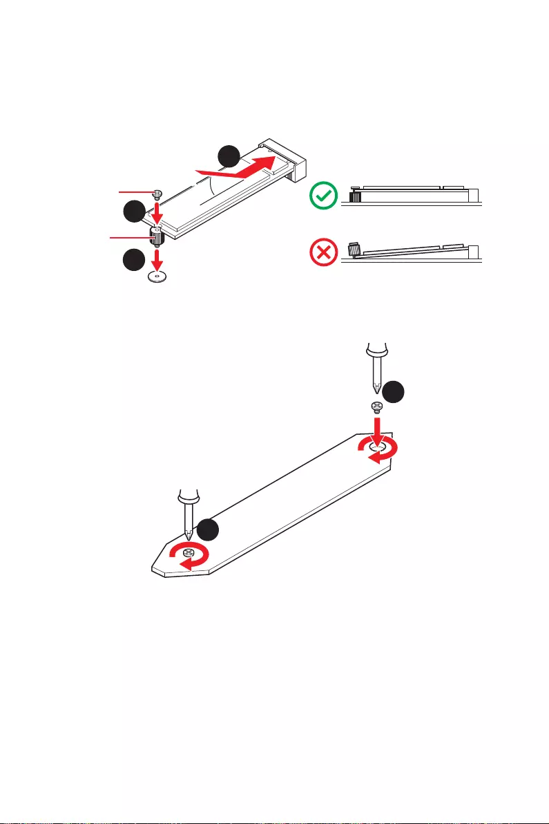
22 Vue d’ensemble des composants
30º30º
5
4
3
Vis 8.5H
Entretoise
3. Si nécessaire, déplacez l’entretoise de manière à l’adapter à la longueur du SSD
M.2.
4. Insérez votre SSD M.2 dans le slot M.2 à un angle de 30 degrés.
5. Fixez le SSD M.2 avec une vis M.2 8.5H.
6.
6
6
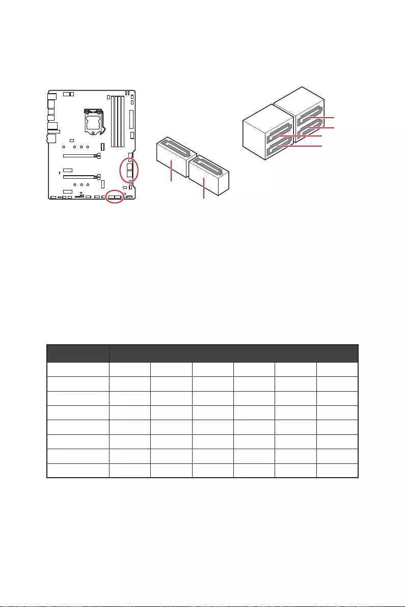
23
Vue d’ensemble des composants
SATA1~6 : Connecteurs SATA 6Gb/s
Ces connecteurs utilisent une interface SATA 6 Gb/s. Chaque connecteur peut être
relié à un appareil SATA.
⚠
Important
∙
Veuillez ne pas plier les câbles SATA à 90° car cela pourrait entraîner une perte de
données pendant la transmission.
∙
Les câbles SATA disposent de prises identiques sur chaque côté. Néanmoins, il est
recommandé de connecter la prise plate sur la carte mère pour un gain d’espace.
∙
Le connecteur SATA2 est indisponible lorsqu’un SSD SATA M.2 est installé dans le
slot M2_1.
∙
Les connecteurs SATA5 et SATA6 sont indisponibles lorsqu’un SSD M.2 est installé
dans le slot M2_2.
SATA1
SATA3
SATA2
SATA4
SATA5
SATA6
Table de combinaison M.2 et SATA
Slot Connecteurs SATA disponibles
M2_1 PCIe SATA PCIe SATA PCIe SATA
M2_2 PCIe PCIe SATA SATA
SATA1
SATA2
SATA3
SATA4
SATA5
SATA6
(SATA : SSD M.2 SATA, PCIe
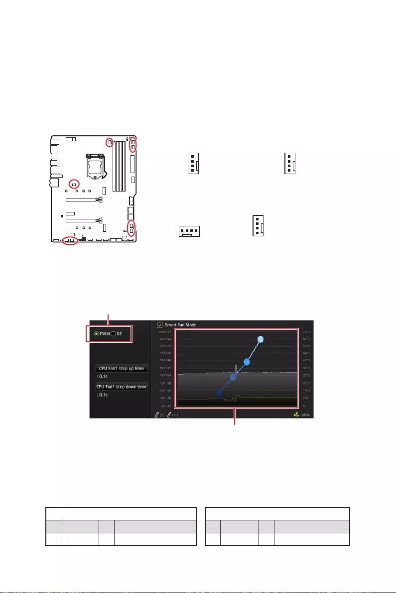
24 Vue d’ensemble des composants
CPU_FAN1, PUMP_FAN1, SYS_FAN1~6 : Connecteurs pour ventilateurs
Les connecteurs pour ventilateurs peuvent être utilisés en mode PWM (Pulse Width
Modulation) et en mode DC. En mode PWM, les connecteurs fournissent une sortie
de 12V constante et ajustent la vitesse des ventilateurs avec un signal de contrôle
de vitesse. En mode DC, les connecteurs contrôlent la vitesse des ventilateurs en
connecteur de ventilateur en mode PWM ou mode DC.
Basculer entre les modes des ventilateurs et ajuster la vitesse
Vous pouvez alterner entre le mode PWM et le mode DC et ajuster la vitesse des
ventilateurs dans le BIOS > HARDWARE MONITOR.
Choisissez le mode PWM ou le mode DC
⚠
Important
Veuillez vous assurer que les ventilateurs fonctionnent correctement après avoir
basculé entre les modes PWM et DC.
Il y a des points de gradient de la vitesse du ventilateur qui
vous permet d’ajuster la vitesse de ventilateur par rapport à la
température du processeur.
Définition des broches en mode PWM
1 Ground 2 +12V
3 Sense 4 Speed Control Signal
Définition des broches en mode DC
1 Ground 2 Voltage Control
3 Sense 4 NC
Définition des broches des connecteurs de ventilateur
Connecteurs pour ventilateurs en mode DC par
défaut
Connecteurs pour
ventilateurs en mode
PWM par défaut
Connecteurs pour
ventilateurs en mode
Auto par défaut
1
SYS_FAN4~6
1
SYS_FAN1~3
1
CPU_FAN1
1
PUMP_FAN1
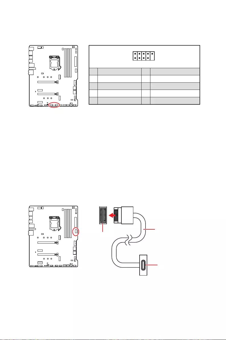
25
Vue d’ensemble des composants
JUSB1~2 : Connecteurs USB 2.0
Ces connecteurs vous permettent de relier des ports USB 2.0 sur le panneau avant.
1
2 10
9
1 VCC 2 VCC
3 4
5 USB0+ 6 USB1+
7 Ground 8 Ground
9 No Pin 10 NC
⚠
Important
∙
Notez que les broches VCC et Terre doivent être branchées correctement afin
d’éviter tout dommage sur la carte mère.
∙
Pour recharger votre iPad, iPhone et iPod par l’intermédiaire d’un port USB, veuillez
installer l’utilitaire MSI DRAGON CENTER.
JUSB4 : Connecteur USB 3.2 Gen 1
avant. Pour plus de sécurité, ce connecteur a été conçu pour offrir une excellente
sens.
JUSB4
sur le panneau
avant
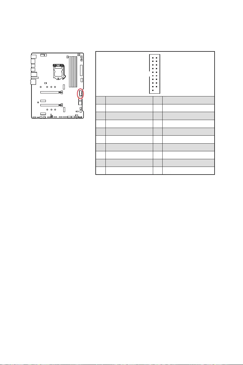
26 Vue d’ensemble des composants
JUSB3 : Connecteur USB 3.2 Gen 1
Ce connecteur vous permet de relier un port USB 3.2 Gen 1 sur le panneau avant.
1
10 11
20
1 Power 11 USB2.0+
2 USB3_RX_DN 12
3 USB3_RX_DP 13 Ground
4 Ground 14 USB3_TX_C_DP
5 USB3_TX_C_DN 15 USB3_TX_C_DN
6 USB3_TX_C_DP 16 Ground
7 Ground 17 USB3_RX_DP
8 18 USB3_RX_DN
9 USB2.0+ 19 Power
10 NC 20 No Pin
⚠
Important
Notez que les câbles d’alimentation et de terre doivent être branchés correctement
afin d’éviter d’endommager la carte.
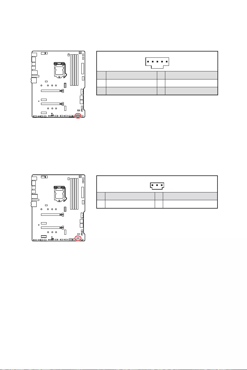
27
Vue d’ensemble des composants
JTBT1 : Connecteur de carte additionnelle Thunderbolt
Ce connecteur vous permet de relier une carte additionnelle Thunderbolt E / S.
1
1 FORCE_PWR 2 SCI_EVENT
3 4
5 GND
JRTD3 : Connecteur Intel RTD3
Ce connecteur vous permet de brancher le connecteur RTD3 sur la carte additionnelle
Thunderbolt.
1
1 WAKE 2 PWR EN
3 GND
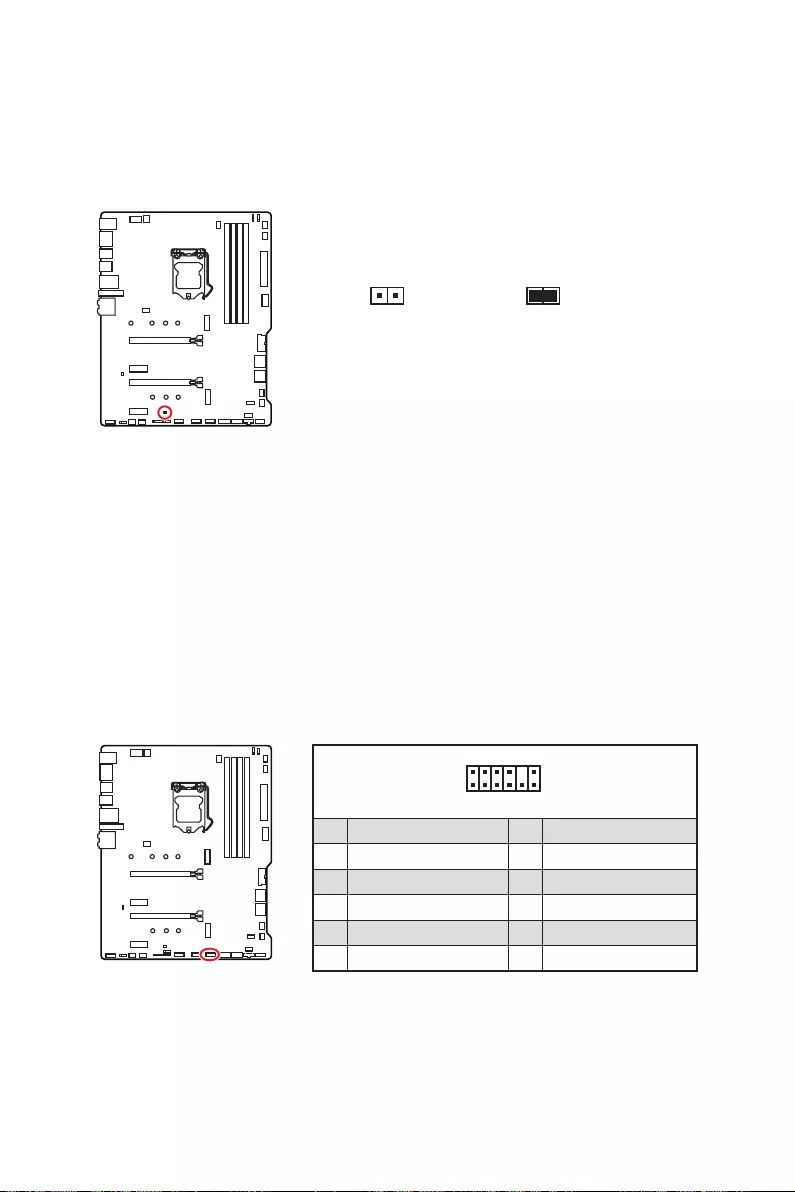
28 Vue d’ensemble des composants
JBAT1 : Cavalier Clear CMOS (Réinitialisation BIOS)
Une mémoire CMOS est intégrée et est alimentée en externe par une batterie située
sur la carte mère afin de conserver les données de configuration système. Si vous
souhaitez nettoyer la configuration système, placez le cavalier sur Effacer CMOS de
manière à nettoyer la mémoire CMOS.
Keep Data
(défaut) Effacer CMOS /
Réinitialiser BIOS
Réinitialiser le BIOS aux valeurs par défaut
1. Eteignez l’ordinateur et débranchez le câble d’alimentation de la prise électrique.
2.
3. Enlevez le couvercle de cavalier du JBAT1.
4.
1
2 12
11
1 SPI Power 2 SPI Chip Select
3
Master In Slave Out (SPI Data)
4
Master In Slave In (SPI Data)
5 Reserved 6 SPI Clock
7 Ground 8 SPI Reset
9 Reserved 10 No Pin
11 Reserved 12 Interrupt Request
JTPM1 : Connecteur de module TPM
Ce connecteur est relié à un module TPM (Trusted Platform Module). Veuillez vous
référer au manuel du module TPM pour plus d’informations.

29
Vue d’ensemble des composants
JCI1 : Connecteur intrusion châssis
Ce connecteur est relié à un câble d’interrupteur intrusion châssis.
Normal
(défaut)
Commencer l’activité
instrusion châssis
Utilisation du détecteur d’intrusion châssis
1. Reliez le connecteur JCI1 à l’interrupteur ou au capteur d’intrusion châssis situé
sur le boîtier du PC.
2. Fermez le couvercle du boîtier.
3. Allez dans le BIOS > SETTINGS (Réglages) > Security (Sécurité) > Chassis
Intrusion Configuration (Configuration intrusion châssis).
4. Réglez Chassis Intrusion (intrusion châssis) sur Enabled (Activé).
5. Appuyez sur F10 pour sauvegarder et quitter. Ensuite appuyez sur la touche Enter
(Entrée) pour choisir Yes (Oui).
6. Désormais, si le boîtier du PC est ouvert quand l’ordinateur est allumé, vous
recevrez un message d’alerte à l’écran.
Réinitialisation de l’alerte intrusion châssis
1. Allez dans le BIOS > SETTINGS (Réglages) > Security (Sécurité) > Chassis
Intrusion Configuration (Configuration intrusion châssis).
2. Mettez Chassis Intrusion (Intrusion châssis) en Reset (Remettre).
3. Appuyez sur F10 pour sauvegarder et quitter. Ensuite appuyez sur la touche Enter
(Entrée) pour choisir Yes (Oui).
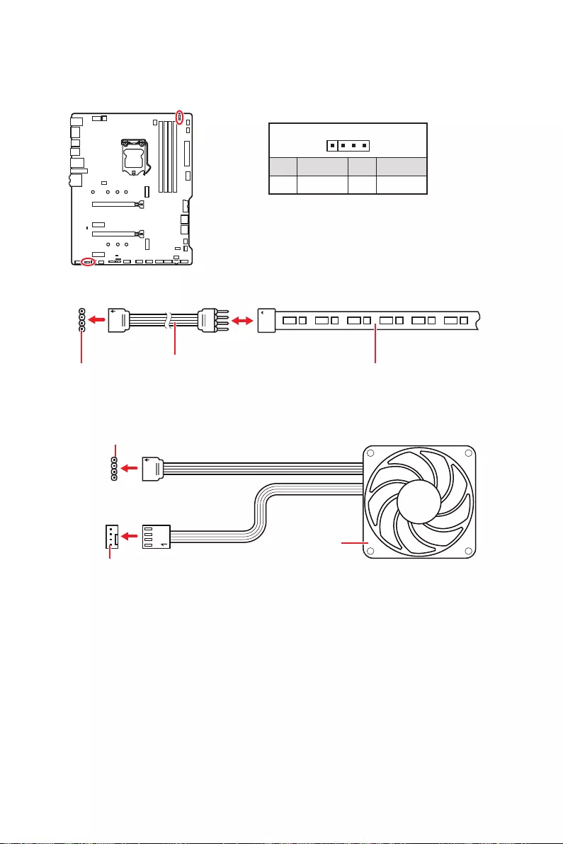
30 Vue d’ensemble des composants
⚠
Important
∙
Le connecteur JRGB supporte des rubans LED RGB (12V / G / R / B) de type 5050
d’une longueur de 2 mètres maximum avec une puissance nominale maximale de 3A
(12V).
∙
Avant d’installer ou de retirer le ruban LED RGB, veillez à toujours éteindre
l’alimentation et à débrancher le câble d’alimentation de la prise électrique.
∙
Veuillez utiliser un logiciel MSI dédié pour contrôler le ruban d’extension LED.
JRGB1~2 : Connecteurs LED RGB
Le connecteur JRGB vous permet de connecter un ruban LED RGB de type 5050 12V.
1
GRB
Connecteur
JRGB
Câble d’extension
RGB Ruban LED RGB de type 5050, sortie 12V
1
1 +12V 2 G
3 R 4 B
Connexion du ruban LED RGB
1
1
GRB
Connecteur JRGB
Connecteur de ventilateur système
Connexion du ventilateur LED RGB
Ventilateur LED RGB
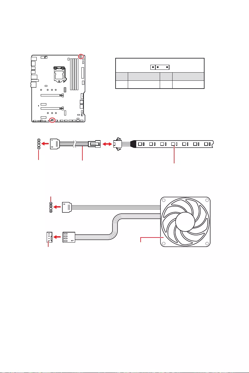
31
Vue d’ensemble des composants
1
1
1
D
+5V
⚠
Attention
Faites attention à bien connecter le bon type de ruban LED. Le connecteur JRGB et le
connecteur JRAINBOW fournissent des tensions différentes. La connexion d’un ruban
LED 5V au connecteur JRGB peut endommager le ruban.
⚠
Important
∙
Le connecteur JRAINBOW supporte jusqu’à des rubans 75 LEDs WS2812B
adressables individuellement (5V / Data / Ground) avec une puissance nominale
maximale de 3A (5V). Dans le cas d’une luminosité de 20%, le connecteur supporte
jusqu’à 200 LED.
∙
Avant d’installer ou de retirer le ruban LED, veillez à toujours éteindre
l’alimentation et à débrancher le câble d’alimentation de la prise électrique.
∙
Veuillez utiliser un logiciel MSI dédié pour contrôler le ruban d’extension LED.
JRAINBOW1~2 : Connecteurs LED RGB addressables
Le connecteur JRAINBOW vous permet de connecter un ruban à LED RGB WS2812B
adressables individuellement 5V.
Connecteur
JRAINBOW
Connecteur JRAINBOW
Connecteur de ventilateur système
Câble d’extension
pour ruban à LED
Ruban LED RGB WS2812B
adressables individuellement,
sortie 5V
1
1 +5V 2 Data
3 No Pin 4 Ground
Connexion du ruban LED RGB addressable
Connexion du ventilateur LED RGB addressable
Ventilateur LED RGB addressable
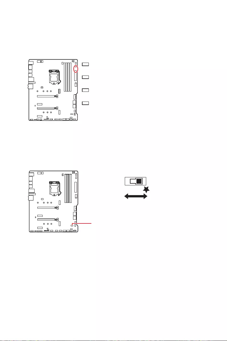
32 Indicateurs LED embarqués
Indicateurs LED embarqués
EZ Debug LED
Ces LEDs indiquent l’état de débogage de la carte mère.
LED_SW1 : Contrôle EZ LED
Cet interrupteur est utilisé pour allumer et éteindre toutes les LED de la carte mère.
LED_SW1
LED_OFF LED_ON
(Défaut)
CPU
son initialisation a échoué.
DRAM
détectée ou que son initialisation a échoué.
VGA
son initialisation a échoué.
BOOT
n’est pas détecté ou que son initialisation a
échoué.

33
Installer OS, Pilotes et Utilitaires
Installer OS, Pilotes et Utilitaires
Veuillez vous référer au site www.msi.com pour télécharger et mettre à jour les
derniers utilitaires et pilotes.
Installer Windows® 10
1. Allumez l’ordinateur.
2. Insérez le disque ou la clé USB d’installation de Windows® 10 dans votre
ordinateur.
3. Appuyez sur le bouton Redémarrer (Restart) du boîtier de l’ordinateur.
4. Appuyez sur la touche F11
entrer dans le menu de démarrage.
5. Choisissez le disque ou la clé USB d’installation de Windows® 10 dans le menu de
démarrage.
6. Appuyez sur n’importe quelle touche lorsqu’apparaît le message [Appuyez sur
n’importe quelle touche pour démarrer du CD ou du DVD] (Press any key to boot
from CD or DVD).
7. Suivez les instructions à l’écran pour installer Windows® 10.
Installer les pilotes
1. Allumez l’ordinateur sous Windows® 10.
2. Insérez le disque MSI® Driver Disc dans le lecteur optique.
3. Cliquez sur la fenêtre popup Choisir quoi faire avec ce disque (Select to choose
what happens with this disc), puis choisissez Lancer DVDSetup.exe (Run
DVDSetup.exe) pour ouvrir l’outil d’installation. Si vous désactivez la fonction
AutoPlay dans le panneau de configuration Windows, vous pouvez quand même
exécuter manuellement DVDSetup.exe à partir du chemin d’accès depuis la racine
du disque de pilotes MSI.
4. L’outil d’installation trouvera et listera tous les pilotes dont vous avez besoin dans
l’onglet Pilotes / Logiciels (Drivers / Software).
5. Cliquez sur le bouton Installer (Install) dans le coin inférieur droit de la fenêtre.
6. L’installation des pilotes commence. Une fois terminée, il vous sera demandé de
redémarrer.
7. Cliquez sur le bouton OK pour terminer.
8. Redémarrez votre ordinateur.
Installer les utilitaires
Avant d’installer les utilitaires, il faut compléter l’installation des pilotes.
1.
2. Cliquez sur l’onglet Utilitaires (Utilities).
3. Choisissez les utilitaires que vous voulez installer.
4. Cliquez sur le bouton Installer (Install) dans le coin inférieur droit de la fenêtre.
5. L’installation des utilitaires commence. Une fois terminée, il vous sera demandé
de redémarrer.
6. Cliquez sur le bouton OK pour terminer.
7. Redémarrez votre ordinateur.

34 UEFI BIOS
UEFI BIOS
Le BIOS UEFI de MSI est compatible avec l’architecture UEFI (Unified Extensible
Firmware Interface). L’infrastructure du firmware du BIOS UEFI présente de
nombreuses nouvelles fonctionnalités et avantages que le BIOS traditionnel ne peut
pas atteindre. Il supportera complètement les futurs PC et les appareils conformes à
l’architecture du firmware UEFI.
⚠
Important
Dans ce guide d’utilisation, le terme BIOS se réfère au BIOS UEFI, sauf indication
contraire.
Avantages de l’UEFI
∙
enregistrer le processus d’autotest du BIOS. Il élimine également le temps à attendre
pour passer en mode CSM pendant le POST.
∙Prend en charge des partitions de disque dur supérieures à 2 To.
∙Prend en charge plus de 4 partitions principales avec une table de partition GUID
(GPT).
∙Prend en charge un nombre illimité de partitions.
∙
appareils peuvent ne pas fournir de compatibilité descendante.
∙
d’exploitation pour s’assurer qu’aucun malware ne perturbe le processus de
démarrage.
Cas d’incompatibilité avec l’UEFI
∙Système d’exploitation Windows 32 bits
système d’exploitation 64 bits.
∙Carte graphique ancienne
message d’avertissement apparaît si aucun support GOP (Graphics Output Protocol)
n’est détecté sur cette carte graphique.
⚠
Important
Nous vous recommandons de remplacer votre carte graphique par un modèle
compatible GOP/UEFI ou d’utiliser la puce graphique intégrée à votre processeur pour
profiter d’un fonctionnement normal.
Comment vérifier le mode BIOS ?
Après être entré dans le BIOS, recherchez le mode BIOS en haut de l’écran.
CPU Temperature:
MotherBoard Temperature:
VCore:
DDR Voltage:
BIOS Mode: UEFI
Mode de démarrage UEFI

35
UEFI BIOS
Configuration du BIOS
Les réglages par défaut fournissent une performance optimale pour la stabilité du
système en conditions normales. Veillez à toujours garder les réglages par défaut
pour éviter d’endommager le système ou tout problème au démarrage, sauf si vous
êtes familier avec le BIOS.
⚠
Important
∙
Le BIOS est constamment mis à jour afin d’offrir de meilleures performances
système. Par conséquent, la description peut différer selon la version de BIOS utilisée
et n’est donc donnée qu’à titre de référence. Vous pouvez aussi vous référer à l’onglet
Help (Aide) pour obtenir la description des fonctions du BIOS.
∙
Les photos ne sont données qu’à titre de référence et peuvent varier selon le produit
que vous achetez.
∙
Les éléments du BIOS peuvent varier selon le processeur.
Entrer dans l’interface Setup du BIOS
Pendant le démarrage, lorsqu’apparaît le message “Press DEL key to enter Setup
Menu, F11 to enter Boot Menu” sur l’écran, veuillez appuyer sur la touche Suppr.
Touches de fonction
F1 : Aide générale
F2 : Ajouter ou supprimer un élément favori
F3 : Entrer dans le menu Favoris
F4 : Entrer dans le menu de réglages du processeur
F5
F6 : Charger les réglages par défaut
F7 : Alterner entre le mode avancé et le mode simplifié
F8 : Charger le profil d’overclocking
F9 : Sauvegarder le profil d’overclocking
F10 : Sauvegarder les modifications et réglages*
F12 : Prendre une capture d’écran et la conserver dans le lecteur flash USB (au
format FAT / FAT32 uniquement)
Ctrl+F : Entrer dans la page de recherche
* Lorsque vous appuyez sur F10, une fenêtre de confirmation apparaît et fournit
l’information de modification. Choisissez entre Oui et Non pour confirmer.
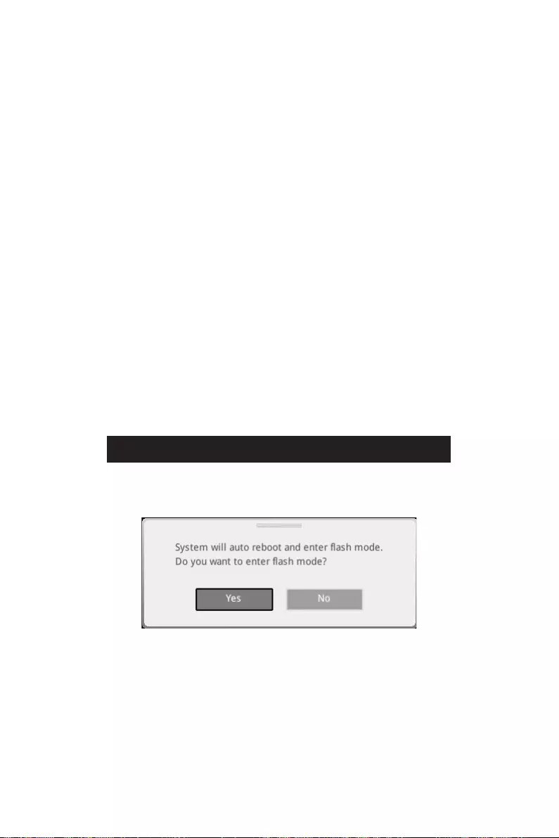
36 UEFI BIOS
Réinitialiser le BIOS
Il se peut que vous ayez besoin de récupérer les réglages BIOS par défaut pour
résoudre des problèmes. Pour réinitialiser les réglages du BIOS, veuillez suivre l’une
des méthodes suivantes :
∙Allez dans le Setup du BIOS et appuyez sur F6 pour charger les réglages par défaut.
∙Clear CMOS sur la carte mère.
⚠
Important
vous référer à la section cavalier Clear CMOS pour en savoir plus sur la réinitialisation
du BIOS.
Mettre le BIOS à jour
Mettre le BIOS à jour avec M-FLASH
Avant la mise à jour :
Veuillez télécharger la dernière version de BIOS compatible à votre carte mère sur le
site MSI. Ensuite, veuillez sauvegarder le nouveau BIOS sur le lecteur flash USB.
Mettre le BIOS à jour :
1. Connectez le lecteur Flash USB contenant le profil à le port USB.
2. Veuillez vous référer aux méthodes suivantes pour passer en mode flash.
▪Redémarrez et appuyez sur la touche Ctrl + F5 pendant le processus de POST et
cliquez sur Yes (Oui) pour redémarrer le système.
▪Redémarrez et appuyez sur la touche Del pendant le processus de POST pour
entrer dans l’interface du BIOS. Cliquez le bouton M-FLASH et cliquez sur Yes
(Oui) pour redémarrer le système.
3. Choisissez un profil BIOS pour commencer la mise à jour du BIOS.
4. Lorsque vous y êtes invité, cliquez sur Yes (Oui) pour lancer la restauration du
BIOS.
5. Une fois la mise à jour terminée, le système redémarrera automatiquement.

37
UEFI BIOS
Mettre le BIOS à jour avec MSI DRAGON CENTER
Avant la mise à jour :
connecté à internet.
Mettre le BIOS à jour :
1. Installez et lancez MSI DRAGON CENTER et accédez à la page Support.
2. Choisissez Live Update et cliquez sur le bouton Advance.
3. Cliquez sur le bouton Scan pour rechercher la dernière version du BIOS.
4. Choisissez le profil BIOS et cliquez sur l’icône Download pour télécharger et
installer la dernière version du BIOS.
5. Cliquez sur Next (Suivant) et choisissez le mode In Windows. Ensuite, cliquez sur
Next (Suivant) et Start (Commencer) pour lancer la mise à jour du BIOS.
6. Une fois la mise à jour terminée, le système redémarrera automatiquement.
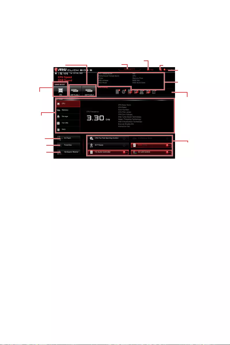
38 UEFI BIOS
EZ Mode
Le mode EZ vous fournit les informations basiques du système et vous permet
de configurer les réglages de base. Si vous souhaitez configurer les réglages du
BIOS, veuillez utiliser le mode Advanced en appuyant sur le switch Setup Mode
(Interrupteur de modes de réglages) ou la touche de fonction F7.
Profil XMP
Informations des
composants
Informations
du système
Barre priorité
de périphérique
démarrage
Boutons de
fonction
Langue
GAME BOOST
Recherche
Capture
d’écran
Interrupteur de
modes de réglages
Moniteur de
matériel
Favoris
∙GAME BOOST
Cette fonction est seulement disponible lorsque la carte mère et le processeur la
supportent.
⚠
Important
Après l’activation de la fonction GAME BOOST, il est conseillé de ne faire aucune
modification dans menu OC et de ne pas charger les réglages par défauts pour
conserver des performances optimales et une bonne stabilité du système.
∙Profil XMP
mémoire. Cette fonction est seulement disponible lorsque le système, la mémoire et
le processeur la supportent.
∙Interrupteur de modes de réglagesF7 pour
commuter entre le mode avancé et le mode simplifié.
∙Capture d’écranF12 pour prendre une
capture d’écran et la conserver dans le lecteur flash USB (au format FAT ou FAT32
uniquement).
∙RechercheCtrl+F pour accéder à la page
de recherche. Cette page vous permet de faire des recherche en utilisant les noms
des éléments du BIOS. Déplacez la souris sur un espace vierge et faites un clic droit
pour quitter la page de recherche.
⚠
Important
Dans la page de recherche, seules les touches de fonction F6, F10 et F12 sont
disponibles.
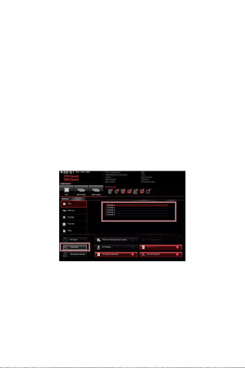
39
UEFI BIOS
∙Langue
∙Informations du système
mémoire, la température du processeur et de la carte mère, le type de carte mère et
de processeur, la capacité mémoire, la version du BIOS et la date d’installation.
∙Barre priorité de périphérique démarrage
aux périphériques pour modifier la priorité au démarrage. Le sens de la priorité va de
gauche à droite.
∙Informations des composants CPU, Memory, Storage, Fan
Info et Help pour afficher les informations du composant connecté.
∙Boutons de fonction activez ou désactivez ces fonctions en cliquant sur ces
boutons. La fonction est activée lorsque le bouton affiche ON.
⚠
Important
Les boutons de fonction peuvent varier selon la carte mère que vous achetez.
∙M-FlashM-Flash qui fournit la
méthode de mise à jour BIOS à l’aide d’un disque flash USB.
∙Moniteur de matérielHardware
Monitor qui vous permet de contrôler manuellement la vitesse des ventilateurs.
∙Favoris F3 pour afficher la fenêtre
Favoris. Il fournit 5 menus pour vous de créer un menu BIOS personnalisé où vous
pourrez sauvegarder et accéder à vos réglages favoris ou fréquemment utilisés.
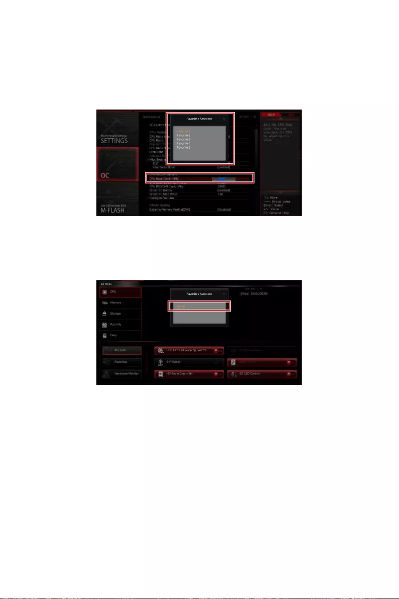
40 UEFI BIOS
▪Ajouter un élément du BIOS au menu Favoris
1. Sélectionnez un élément du BIOS pas seulement dans le menu du BIOS mais
également sur la page de recherche.
2. Faites un clic droit ou appuyez sur la touche F2.
3. Choisissez une page de favoris et cliquez sur OK.
▪Supprimer un élément du BIOS du menu des favoris
1. Sélectionnez un élément du BIOS dans le menu Favoris.
2. Faites un clic droit ou appuyez sur la touche F2.
3. Choisissez Delete (Effacer) et cliquez sur OK.

41
UEFI BIOS
Advanced Mode (mode avancé)
Appuyez sur le Setup Mode switch (interrupteur de modes de réglages) ou sur la
touche de fonction F7 pour commuter entre le mode simplifié et le mode avancé.
Sélection du
menu BIOS
Ecran de menu
Sélection du
menu BIOS
∙Sélection du menu BIOS
▪SETTINGS (Réglages)
du démarrage des périphériques.
▪OC
peut améliorer les performances.
▪M-FLASH
▪OC PROFILE
▪HARDWARE MONITOR (Moniteur de matériel)
ventilateurs et de surveiller la tension du système.
▪BOARD EXPLORER
la carte mère.
∙Ecran de menu
configurer.

42 UEFI BIOS
OC Menu (menu overclocking)
Ce menu vous permet de configurer les fréquences et les tensions pour l’overclocking.
Veuillez noter que l’augmentation de la fréquence et de la tension peut être bénéfique
à la qualité de l’overclocking mais peut également causer l’instabilité du système.
⚠
Important
∙
L’overclocking manuel du PC n’est recommandé que pour les utilisateurs avancés.
∙
L’overclocking n’est pas garanti et une mauvaise manipulation peut rendre nulle
votre garantie et sévèrement endommager votre matériel.
∙
Si vous n’êtes pas familier avec l’overclocking, nous vous recommandons d’utiliser
GAME BOOST pour un overclocking simplifié et plus stable.
∙
Les éléments du BIOS dans le menu OC peuvent varier selon le processeur.
▶OC Explore Mode [Expert]
Active ou désactive le mode Normal ou Expert des réglages OC.
[Normal] Fournit les réglages OC standards dans les réglages BIOS.
[Expert] Fournit les réglages OC avancés pour les utilisateurs avancés et à
configurer dans les réglages BIOS.
Remarque : Nous utilisons le symbole * pour indiquer les réglages OC du mode
Expert.
▶CPU Ratio Apply Mode [All Core]*
Règle le mode d’application en cours pour le ratio. Ce menu n’apparaît que si le
processeur installé est compatible avec Turbo Boost.
▶CPU Ratio [Auto]
Définit le ratio servant à déterminer la vitesse d’horloge du processeur. Ce menu
n’apparaît que lorsque CPU Ratio Apply Mode est réglé sur All Core.
▶X-Core Ratio Limit [Auto]
Permet de définir le ratio du processeur pour différent nombre de cœurs actifs. Ces
menus n’apparaissent que lorsque CPU Ratio Apply Mode est réglé sur Turbo Ratio.
▶Numbers of CPU Cores of Group X [Auto]*
Définit le nombre de cœurs CPU et le met en groupe pour exécuter le ratio turbo du
CPU cible. Le groupe suivant doit avoir plus de cœurs CPU que le groupe précédent.
Ces menus n’apparaissent que lorsque CPU Ratio Apply Mode est réglé sur Turbo
Ratio.
▶Target CPU Turbo Ratio Group X [Auto]
Définit la valeur cible du ratio turbo CPU pour le groupe de cœurs CPU assigné.
La valeur cible du ratio turbo CPU ne doit pas être supérieure à la précédente. Ces
menus n’apparaissent que lorsque CPU Ratio Apply Mode est réglé sur Turbo Ratio.
▶Adjusted CPU Frequency
Montre la fréquence ajustée du processeur. Fonctionne uniquement en lecture seule.

43
UEFI BIOS
▶Core X X of X xxxx MHz [Auto]
Permet de définir le ratio du processeur pour différent nombre de cœurs actifs. Ces
menus n’apparaissent que lorsque CPU Ratio Apply Mode est est réglé sur Per Core.
▶ Turbo Ratio Oset Value [Auto]
Définit la valeur de décalage du ratio turbo CPU. Ce menu n’apparaît que lorsque CPU
Ratio Apply Mode est mis en Turbo Ratio Offset.
▶CPU Ratio Mode [Dynamic Mode]*
Choisit le mode d’opération du ratio du processeur. Ce menu apparaît lorsque vous
réglez le ratio manuellement.
[Fixed Mode] Fixe le ratio.
[Dynamic Mode] Le ratio sera modifié dynamiquement selon la charge du
processeur.
▶ CPU Ratio Oset When Running AVX [Auto]
pour la dissipation de chaleur lors de l’exécution du jeu d’instruction AVX. Mis en
processeur installé prend cette fonction en charge.
▶Ring Ratio [Auto]
dépend du processeur installé.
▶Adjusted Ring Frequency
▶GT Ratio [Auto]
Règle le ratio de la puce graphique intégrée. La gamme de valeur valides dépend du
processeur installé.
▶Adjusted GT Frequency
Montre la fréquence de la puce graphique intégrée modifiée. Fonctionne en lecture
seule.
▶+Misc Setting*
suivants, relatifs aux fonctionnalités du processeur.
▶CPU Base Clock (MHz) [Default]
Définit le fréquence de base du processeur. Vous pouvez overclocker le processeur
en ajustant sa valeur. Veuillez noter que les résultats de l’overclocking ne sont pas
garantis. Ce menu est seulement disponible si le processeur installé supporte cette
fonction.

44 UEFI BIOS
▶CPU Base Clock Apply Mode [Auto]*
Définit le mode d’application pour le réglage de la fréquence de base du processeur.
[Auto] Ce réglage est configuré automatiquement par le BIOS.
[Next Boot] Le processeur fonctionne avec une fréquence de base paramétrée pour
le prochain démarrage.
[Immediate] Le processeur fonctionne avec une fréquence de base paramétrée
immédiatement.
▶Clockgen Features sub-menu
Appuyez sur la touche Entrée
fonctionnalités détaillées de clockgen.
▶ Extreme Memory Prole (XMP) [Disabled]
La technologie d’overclocking X.M.P. (Extreme Memory Profile) permet un
overclocking par l’intermédiaire du module de mémoire. Activez la technologie XMP
ou sélectionnez un profil de module de mémoire pour overclocker la mémoire. Ce
menu est seulement disponible si vous disposez de modules de mémoire prenant en
charge la technologie XMP.
▶DRAM Reference Clock [Auto]*
Définit la valeur d’horloge de référence de la mémoire. La gamme de valeur valide
dépend du processeur installé. Ce menu est seulement disponible si le processeur
installé supporte cette fonction.
▶DRAM Frequency [Auto]
Définit la fréquence de la mémoire. Veuillez noter que les résultats de l’overclocking
ne sont pas garantis.
▶Adjusted DRAM Frequency
Affiche la fréquence ajustée de la mémoire. Fonctionne en lecture seule.
▶Load Memory Presets [Disabled]*
Load OC Memory Preset optimisera les timings et les tensions des modules installés.
▶Memory Try It ! [Disabled]
Memory Try It! permet d’améliorer la compatibilité ou les performances en optimisant
les préréglages de la mémoire.
▶DRAM Timing Mode [Link]
Choisit le mode de latences mémoire.
[Link] Ceci vous permet de configurer les latences DRAM pour tous les canaux
de mémoire.
[UnLink] Ceci vous permet de configurer les latences DRAM pour chaque canal
de mémoire.
▶ Advanced DRAM Conguration
Appuyez sur la touche Entrée
la synchronisation de mémoire de chaque barrette de mémoire. Le système peut être
instable ou peut ne plus redémarrer après le changement de la synchronisation de la
données CMOS et entrez ensuite dans le BIOS pour charger les réglages par défaut).

45
UEFI BIOS
▶Memory Fast Boot [Auto] *
Active ou désactive l’initialisation et le test de la mémoire à chaque démarrage.
[Auto] Ce réglage est automatiquement configuré par le BIOS.
[Enabled] La mémoire imitera complètement l’archive de la première initiation
et la première formation. La mémoire n’est ensuite plus initialisée ni
testée au moment du démarrage, de façon à accélérer le démarrage du
système.
[Disabled] La mémoire est initialisée et testée à chaque démarrage.
▶DigitALL Power sub-menu
Appuyez sur la touche Entrée
vous pouvez installer des conditions de protection sur tension / courant / température
pour le processeur.
▶CPU Core / GT Voltage Mode [Auto]*
Définit le mode pour la tension du cœur CPU et la tension GT.
▶CPU Core Voltage Mode [Auto]*
Définit le mode pour la tension du cœur CPU.
▶CPU Voltages control [Auto]
Permet de définir les tensions relatives au processeur. En mode Auto, le BIOS
configure ces tensions automatiquement. Vous pouvez également les paramétrer
manuellement.
▶DRAM Voltages control [Auto]
Permet de définir les tensions relatives à la mémoire. En mode Auto, le BIOS
configure ces tensions automatiquement. Vous pouvez également les paramétrer
manuellement.
▶PCH Voltages control [Auto]
Permet de définir les tensions relatives à la puce PCH. En mode Auto, le BIOS
configure ces tensions automatiquement. Vous pouvez également les paramétrer
manuellement.
▶CPU Memory Changed Detect [Enabled]*
Active ou désactive les messages d’alerte système au démarrage suite au
remplacement du processeur ou de la mémoire.
[Enabled] Le système montre un message d’alerte pendant le démarrage et vous
devez charger les réglages par défaut pour les nouveaux périphériques.
[Disabled] Désactive cette fonction et garde les réglages BIOS actuels.
▶OC Quick View Timer [3 Sec]*
Définit la durée pendant laquelle les valeurs de réglages d’overclocking sont affichées
sur l’écran. Mis en Désactivé, le BIOS n’affichera pas les variations de réglages
d’overclocking.
▶ CPU Specications sub-menu
Appuyez sur la touche Entrée
menu à tout moment en appuyant sur la touche [F4]. Fonctionne en lecture seule.

46 UEFI BIOS
▶MEMORY-Z sub-menu
Appuyez sur la touche Entrée
les réglages et timings de la mémoire installée. Vous pouvez également accéder à ce
▶CPU Features sub-menu
Appuyez sur la touche Entréeu. Vous pouvez activer
ou désactiver les fonctionnalités et technologies du processeur pour protéger le
processeur et améliorer les performances du système.

1
Содержание
Содержание
Безопасное использование продукции ……………………………………………………. 3
Технические характеристики ………………………………………………………………….. 4
Комплект поставки …………………………………………………………………………………. 9
Задняя панель портов ввода/ вывода ……………………………………………………. 10
………………………………………………. 10
…………………………………………………………………… 10
Realtek Audio Console …………………………………………………………………………….. 11
Компоненты материнской платы …………………………………………………………… 14
………………………………………………………………………………. 15
…………………………………………………………………………………………… 16
…………………………………………………………. 17
………………………………………………. 18
…………………………………………………… 19
…………………………………………………… 19
………………………………………………………………. 20
………………………………………………………………… 22
……………….. 23
…………………………………………………………………….. 24
………………………………………………………. 24
………………………………………………………………….. 25
………………….. 26
……………………………………………………………………….. 26
………………………………. 27
……………………………………………………………………. 27
………………………………………………….. 28
…………………………………………………………………… 29
……………………………………………. 30
Встроенные индикаторы ……………………………………………………………………….. 31
………………………………………………………………………….. 31
…………………… 31
Установка ОС, драйверов и утилит …………………………………………………………. 32
…………………………………………………………………………… 32
……………………………………………………………………………… 32
……………………………………………………………………………………. 32
UEFI BIOS ………………………………………………………………………………………………. 33
………………………………………………………………………………………. 34
……………………………………………………………………………. 34

2Содержание
…………………………………………………………………………………………….. 35
……………………………………………………………………………………. 35
……………………………………………………………………………………………….. 37
………………………………………………………………………………………. 41
………………………………………………………………………………………………… 42

3
Безопасное использование продукции
Безопасное использование продукции
∙
∙
∙
∙
∙
∙
∙
∙
∙
∙
∙
∙
∙
∙
∙
▪
▪
▪
▪
▪
∙

4Технические характеристики
Технические характеристики
Процессор
Чипсет Intel® Z490
Память
∙
∙
▪
▪
▪
▪
∙
∙
∙
Слоты расширения
∙
∙
∙
Встроенная
графика
∙
∙
Поддержка Multi-
GPU ∙
Подключение
накопителей
∙
∙
▪
▪
/2280/ 22110*
▪
/2280**
▪

5
Технические характеристики
Подключение
накопителей
M2_1.
RAID
∙
∙
LAN
USB
∙
▪
▪
▪
▪
∙
▪
Аудио
∙
∙
Wi-Fi/Bluetooth
∙
∙
∙
∙

6Технические характеристики
Разъемы задней
панели
∙
∙
∙
∙
∙
∙
∙
∙
∙
∙
∙
Разъемы на плате
∙
∙
∙
∙
∙
∙
∙
∙
∙
∙
∙
∙
∙
∙
∙
∙
∙
∙
∙
Параметры
индикаторов
∙
∙
7
Технические характеристики
Контроллер ввода-
вывода NUVOTON NCT6687
Аппаратный
мониторинг
∙
∙
∙
Форм-фактор ∙
∙
Параметры BIOS
∙
∙UEFI AMI BIOS
∙ACPI 6.2, SM BIOS 3.2
∙
Программное
обеспечение
∙
∙DRAGON CENTER
∙Intel Extreme Tuning Utility
∙MSI App Player (BlueStacks)
∙Open Broadcaster Software (OBS)
∙
∙Google Chrome™, Google Toolbar, Google Drive
∙Norton™ Internet Security Solution
Функции Dragon
Center
∙Gaming Mode
∙Gaming Hotkey
∙LAN Manager
∙Mystic Light
∙Ambient Link
∙User Scenario
∙Monitor(Hardware
Monitor)
∙True Color
∙Live Update
∙DPC Latency tuner
∙Speed Up
∙Smart Tool
∙Super Charger
download.msi.com/manual/mb/
DRAGONCENTER2.pdf

8Технические характеристики
Эксклюзивные
функции
∙
▪Audio Boost
∙
▪2.5G LAN
▪LAN Manager
▪Intel WiFi
∙
▪Extended Heatsink Design
▪M.2 Shield Frozr
▪Pump Fan
▪Smart Fan Control
∙
▪Mystic Light
▪Mystic Light Extension (RGB)
▪Mystic Light Extension (RAINBOW)
▪Mystic Light Sync
▪EZ DEBUG LED
▪EZ LED Control
∙
▪PCIe Steel Armor
▪
∙
▪
▪DDR4 Boost
▪Core Boost
▪GAME Boost
▪Lightning USB 20G
▪USB 3.2 Gen 2 10G
▪
▪
▪Dual CPU Power
∙
▪DRAGON CENTER
▪Click BIOS 5
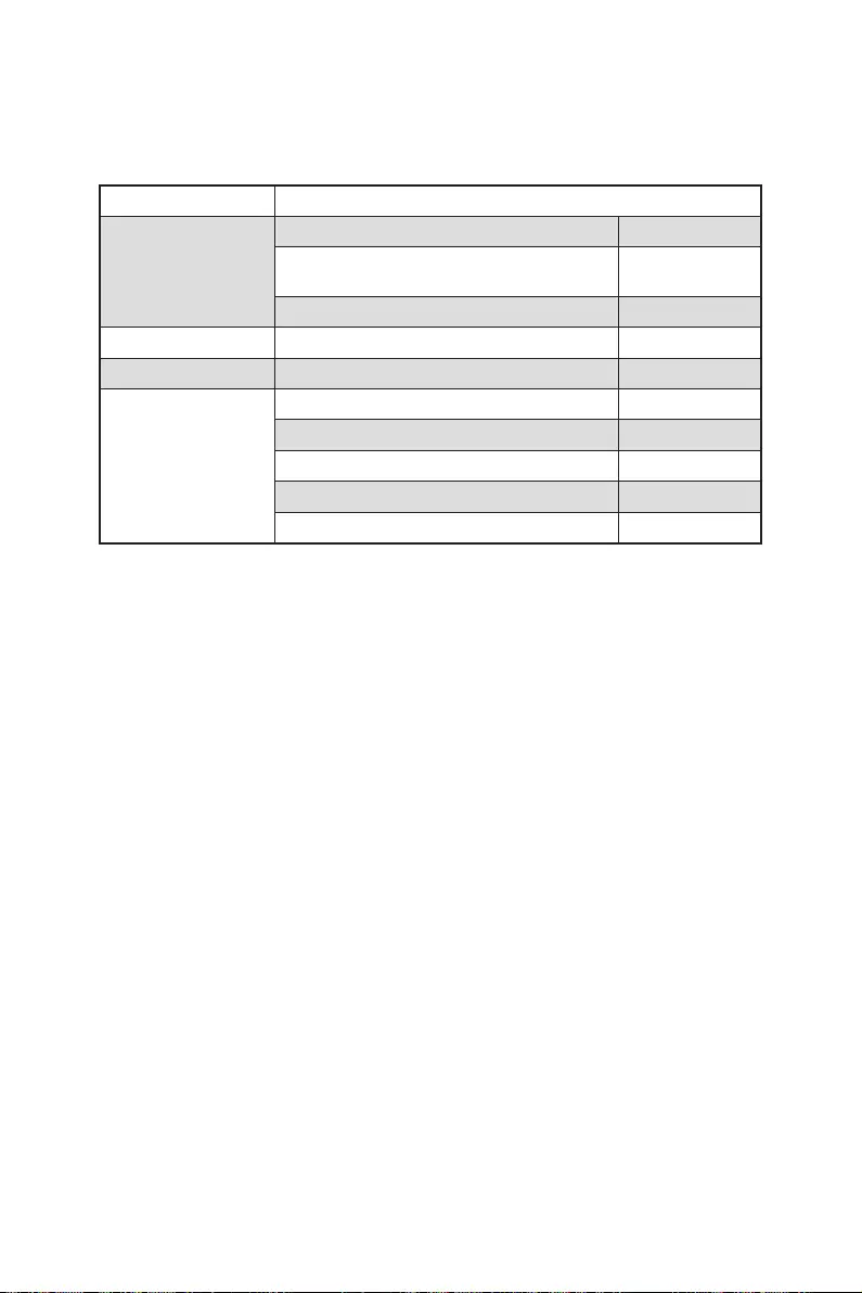
9
Комплект поставки
Комплект поставки
Материнская плата MPG Z490 GAMING EDGE WIFI
Документы
1
1
1
Диск с утилитами 1
Кабели 1
Аксессуары
1
1
1
1
1
⚠
Внимание!
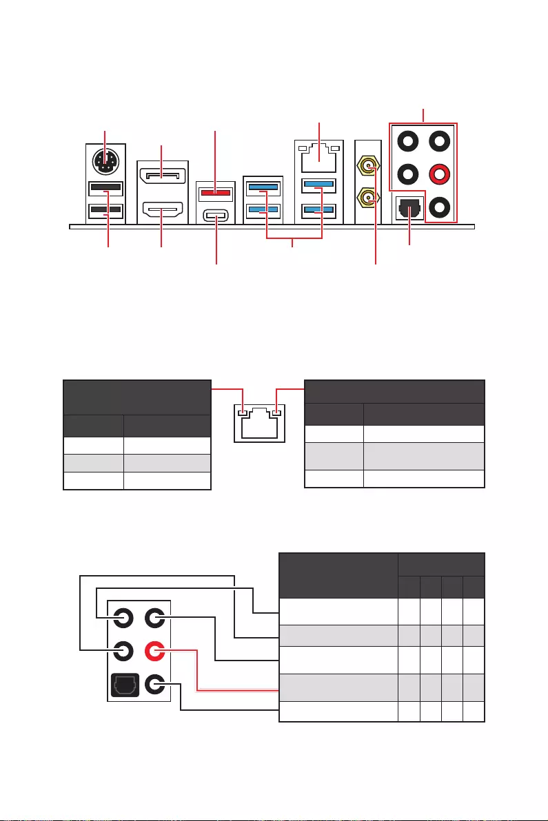
10 Задняя панель портов ввода/ вывода
Задняя панель портов ввода/ вывода
PS/2
Displayport
USB 2.0
Конфигурация портов Аудио
Порты Аудио Канал
2468
(Пусто
Подключение/ Работа
индикатора
Состояние Описание
Скорость передачи данных
Состояние Описание
Таблица состояний индикатора порта LAN
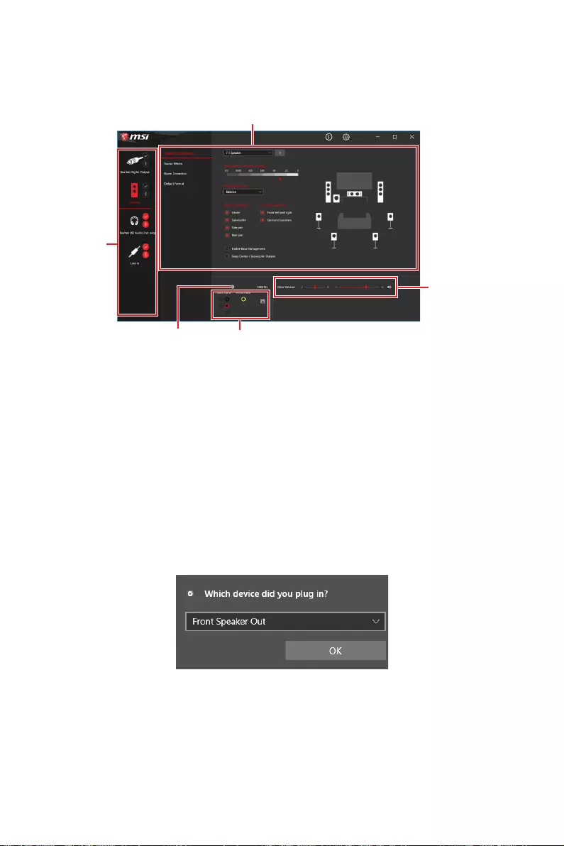
11
Задняя панель портов ввода/ вывода
Realtek Audio Console
∙ Выбор устройства
∙ Дополнительные эффекты
∙ Мастер-громкость
∙ Состояние разъемов
∙ Настройки подключений
Автоматическое всплывающее диалоговое окно
⚠
Внимание!

12 Задняя панель портов ввода/ вывода
Подключение наушников и микрофона
Подключение внешнего стерео усилителя (колонок)
Подключение звуковой системы 7.1
AUDIO INPUT
AUDIO INPUT
Rear Front
Side Center/
Subwoofer

13
Задняя панель портов ввода/ вывода
Установка антенн
1.
2.
1
2

14 Компоненты материнской платы
Компоненты материнской платы
DIMMA1
CPU_FAN1
DIMMA2
DIMMB1
DIMMB2
JRGB2
JRAINBOW2
PUMP_FAN1
SYS_FAN6
SYS_FAN5
SYS_FAN1
SYS_FAN4
LED_SW1
JRTD3
JFP1
JTBT1
SATA6
SATA5
JTPM1
JUSB1
JUSB2
JFP2
JT1
JBAT1
JRAINBOW1
ATX_PWR1
JUSB4
JUSB3
CPU_PWR1
CPU_PWR2
SYS_FAN3
SYS_FAN2
JRGB1
JAUD1
PCI_E4
PCI_E3
M2_2
M2_1
JCI1
PCI_E2
PCI_E1
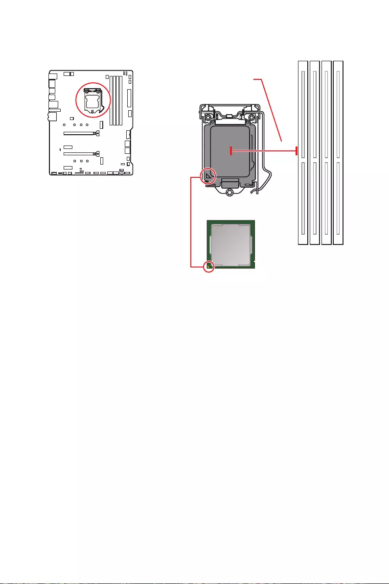
15
Компоненты материнской платы
⚠
Внимание!
∙
∙
∙
∙
∙
∙
∙
∙
Процессорный сокет
Процессор LGA 1200
выемки
золотой треугольник
50.6 мм
Расстояние от центра
процессора до ближайшего
слота DIMM.

16 Компоненты материнской платы
Слоты DIMM
DIMMA1 DIMMB1
Канал A Канал B
DIMMA2 DIMMB2
Рекомендации по установке модулей памяти
⚠
Внимание!
∙
DIMMA2.
∙
∙
DRAM Frequency
∙
∙
∙
DIMMB2 DIMMB2
DIMMB1
DIMMA2 DIMMA2 DIMMA2
DIMMA1

17
Компоненты материнской платы
PCI_E1~4: Слоты расширения PCIe
⚠
Внимание!
∙
MSI Gaming Series Graphics Card Bolster
∙
PCI_E1.
∙
PCI_E1: PCIe 3.0 x16 (CPU)
PCI_E3: PCIe 3.0 x4 (PCH)
PCI_E2: PCIe 3.0 x1 (PCH)
PCI_E4: PCIe 3.0 x1 (PCH)
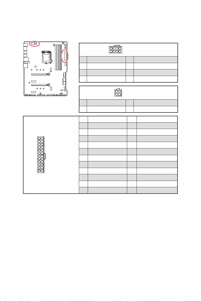
18 Компоненты материнской платы
24
131
12
ATX_PWR1
1 +3.3V 13 +3.3V
2 +3.3V 14
3 Ground 15 Ground
4 +5V 16
5 Ground 17 Ground
6 +5V 18 Ground
7 Ground 19 Ground
8 PWR OK 20 Res
9 5VSB 21 +5V
10 +12V 22 +5V
11 +12V 23 +5V
12 +3.3V 24 Ground
5
4 1
8CPU_PWR1
1 Ground 5 +12V
2 Ground 6 +12V
3 Ground 7 +12V
4 Ground 8 +12V
⚠
Внимание!
CPU_PWR1, ATX_PWR1: Разъемы питания
3
2 1
4CPU_PWR2
1 Ground 3 +12V
2 Ground 4 +12V
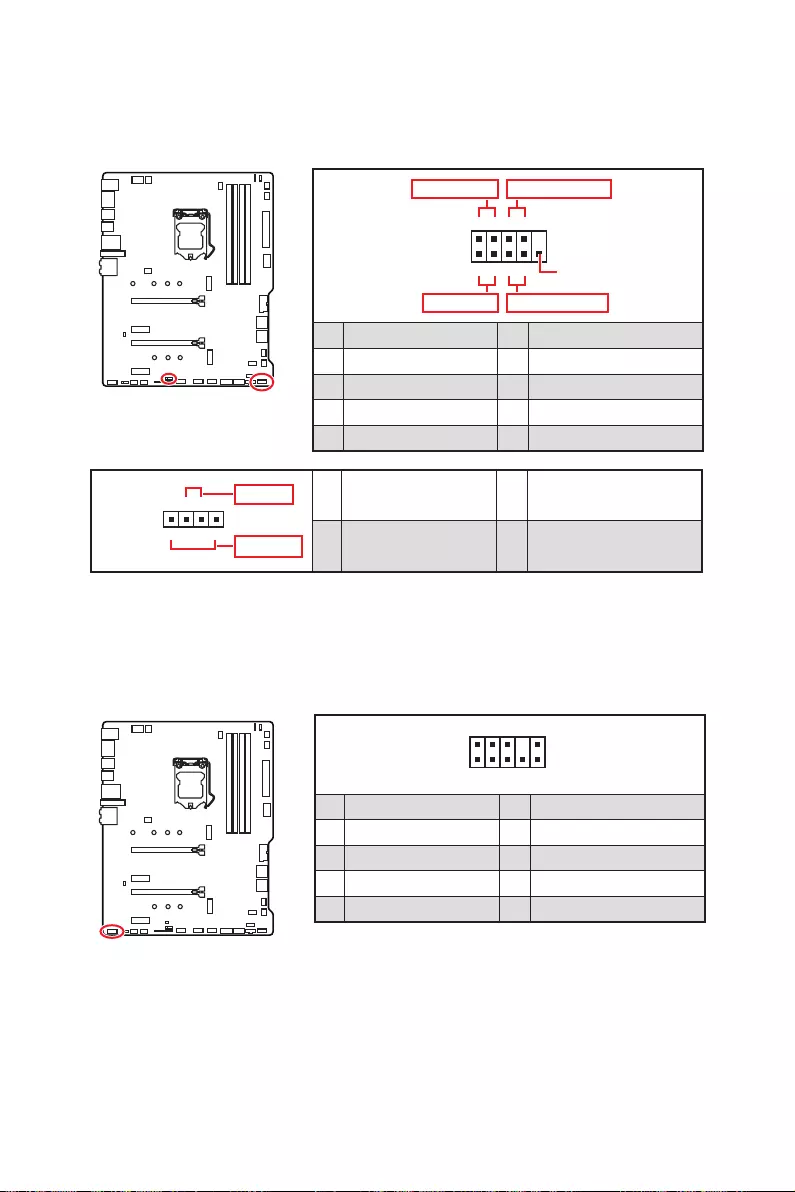
19
Компоненты материнской платы
JFP1, JFP2: Разъемы передней панели
1
2 10
9
+
+
+
+
Power LED
HDD LED Reset Switch
Reserved
Power Switch
JFP1
1 HDD LED + 2 Power LED +
3 4
5 Reset Switch 6 Power Switch
7 Reset Switch 8 Power Switch
9 Reserved 10 No Pin
1
JFP2
+
+
Speaker
Buzzer 1 2 Buzzer +
3 4 Speaker +
JAUD1: Разъем аудио передней панели
1
2 10
9
1 MIC L 2 Ground
3 MIC R 4 NC
5 Head Phone R 6 MIC Detection
7 SENSE_SEND 8 No Pin
9 Head Phone L 10 Head Phone Detection

20 Компоненты материнской платы
M2_1~2: Разъемы M.2 (Ключ M)
⚠
Внимание!
∙
∙
⚽
Видео Инструкция
1
1
2
Установка модуля M.2
1.
2.

21
Компоненты материнской платы
30º30º
5
4
3
3.
4.
5.
6.
6
6

22 Компоненты материнской платы
SATA1~6: Разъемы SATA 6Гб/с
⚠
Внимание!
∙
∙
∙
∙
Таблица комбинации для слотов M.2 и SATA
Слот Доступные разъемы SATA
M2_1 PCIe SATA PCIe SATA PCIe SATA
M2_2 PCIe PCIe SATA SATA
SATA1
SATA2
SATA3
SATA4
SATA5
SATA6
(SATA: M.2 SATA SSD, PCIe
SATA1
SATA3
SATA2
SATA4
SATA5
SATA6
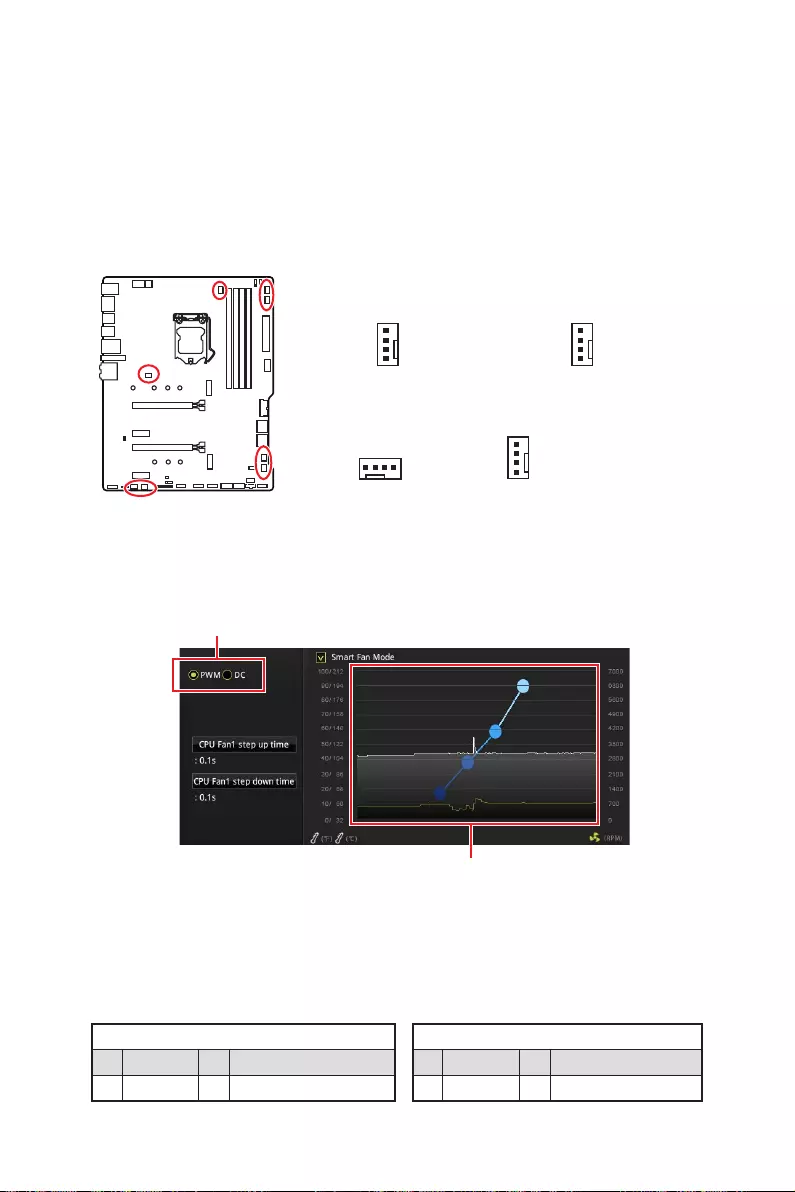
23
Компоненты материнской платы
CPU_FAN1, PUMP_FAN1, SYS_FAN1~6: Разъемы вентиляторов
Переключение режимов работы и скорости вращения вентилятора
BIOS > HARDWARE MONITOR
PWMDC
⚠
Внимание!
Назначение контактов разъема для режима PWM
1 Ground 2 +12V
3 Sense 4 Speed Control Signal
Назначение контактов разъема для режима DC
1 Ground 2 Voltage Control
3 Sense 4 NC
Назначение контактов разъема для подключения вентилятора
Разъем с управлением постоянным током
по умолчанию
Разъем с PWM
управлением по
умолчанию
Разъем с автоматическим
управлением по
умолчанию
1
SYS_FAN4~6
1
SYS_FAN1~3
1
CPU_FAN1
1
PUMP_FAN1
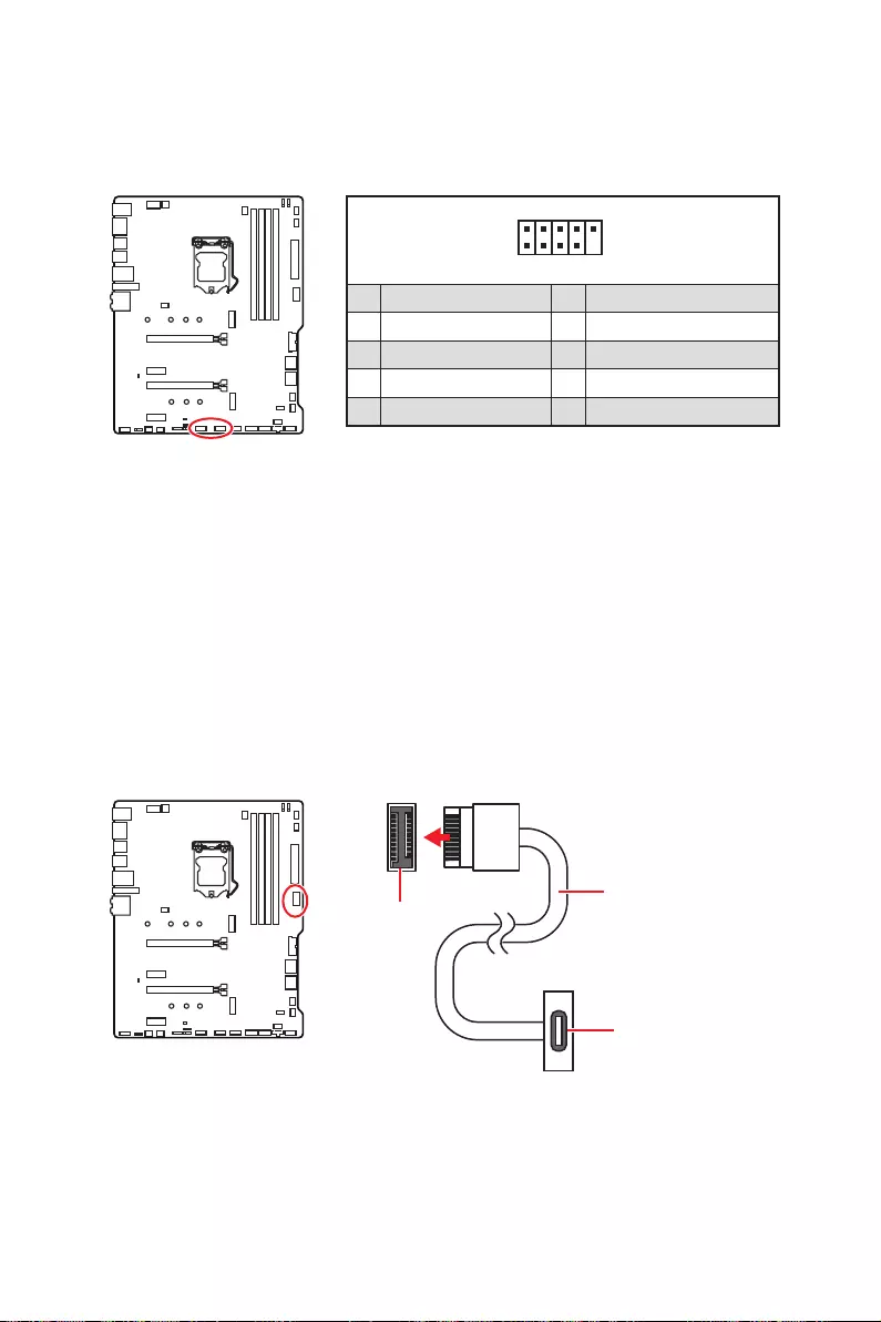
24 Компоненты материнской платы
JUSB1~2: Разъемы USB 2.0
1
2 10
9
1 VCC 2 VCC
3 4
5 USB0+ 6 USB1+
7 Ground 8 Ground
9 No Pin 10 NC
⚠
Внимание!
∙
∙
JUSB4: Разъем USB 3.2 Gen 1 Type-C
JUSB4

25
Компоненты материнской платы
JUSB3: Разъем USB 3.2 Gen 1
1
10 11
20
1 Power 11 USB2.0+
2 USB3_RX_DN 12
3 USB3_RX_DP 13 Ground
4 Ground 14 USB3_TX_C_DP
5 USB3_TX_C_DN 15 USB3_TX_C_DN
6 USB3_TX_C_DP 16 Ground
7 Ground 17 USB3_RX_DP
8 18 USB3_RX_DN
9 USB2.0+ 19 Power
10 NC 20 No Pin
⚠
Внимание!
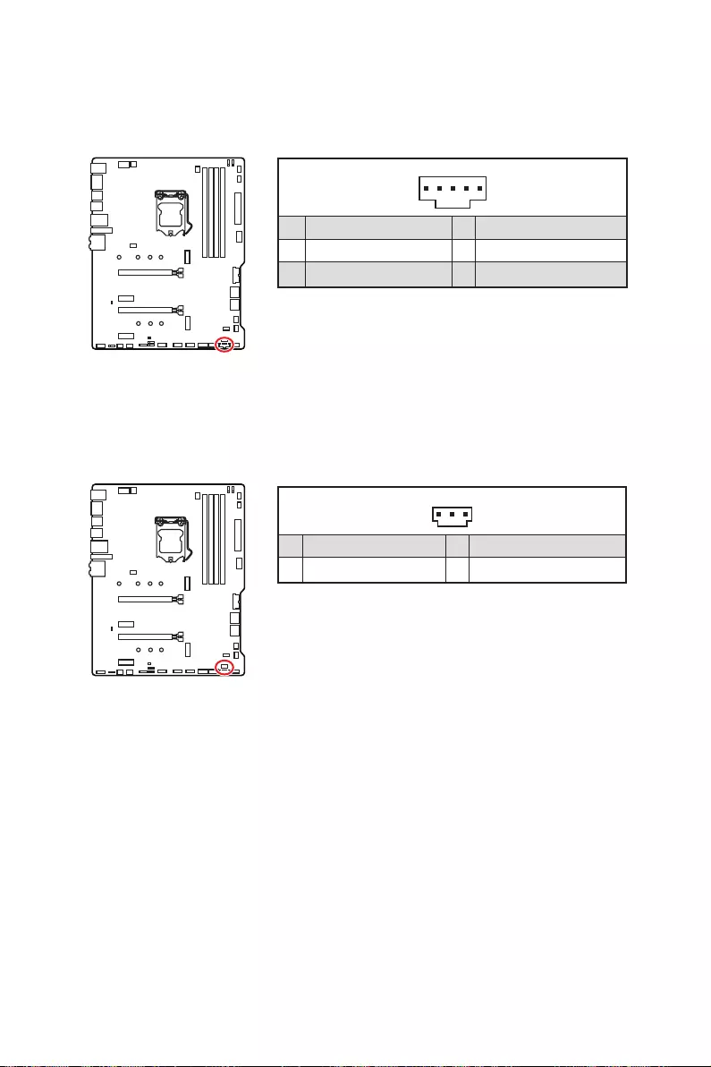
26 Компоненты материнской платы
JTBT1: Разъем для установки карты расширения Thunderbolt
Thunderbolt.
1
1 FORCE_PWR 2 SCI_EVENT
3 4
5 GND
JRTD3: Разъем Intel RTD3
1
1 WAKE 2 PWR EN
3 GND
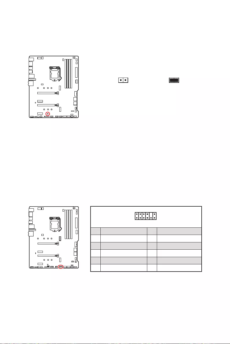
27
Компоненты материнской платы
JBAT1: Джампер очистки данных CMOS (Сброс BIOS)
Сброс настроек BIOS до значений по умолчанию
1.
2.
3.
4.
1
2 12
11
1 SPI Power 2 SPI Chip Select
3
Master In Slave Out (SPI Data)
4
Master In Slave In (SPI Data)
5 Reserved 6 SPI Clock
7 Ground 8 SPI Reset
9 Reserved 10 No Pin
11 Reserved 12 Interrupt Request
JTPM1: Разъем модуля ТРМ

28 Компоненты материнской платы
JCI1: Разъем датчика открытия корпуса
Использование датчика открытия корпуса
1. JCI1.
2.
3. BIOS > SETTINGS > Security > Chassis Intrusion Configuration.
4. Chassis IntrusionEnabled.
5. F10
EnterYes.
6.
Сброс сообщения об открытии корпуса
1. BIOS > SETTINGS > Security > Chassis Intrusion Configuration.
2. Chassis Intrusion, Reset.
3. F10
EnterYes.

29
Компоненты материнской платы
⚠
Внимание!
∙
∙
∙
JRGB1~2: Разъемы RGB LED
1
GRB
JRGB
1
1 +12V 2 G
3 R 4 B
Подключение RGB светодиодных лент
1
1
GRB
Подключение вентиляторов с RGB светодиодной подсветкой
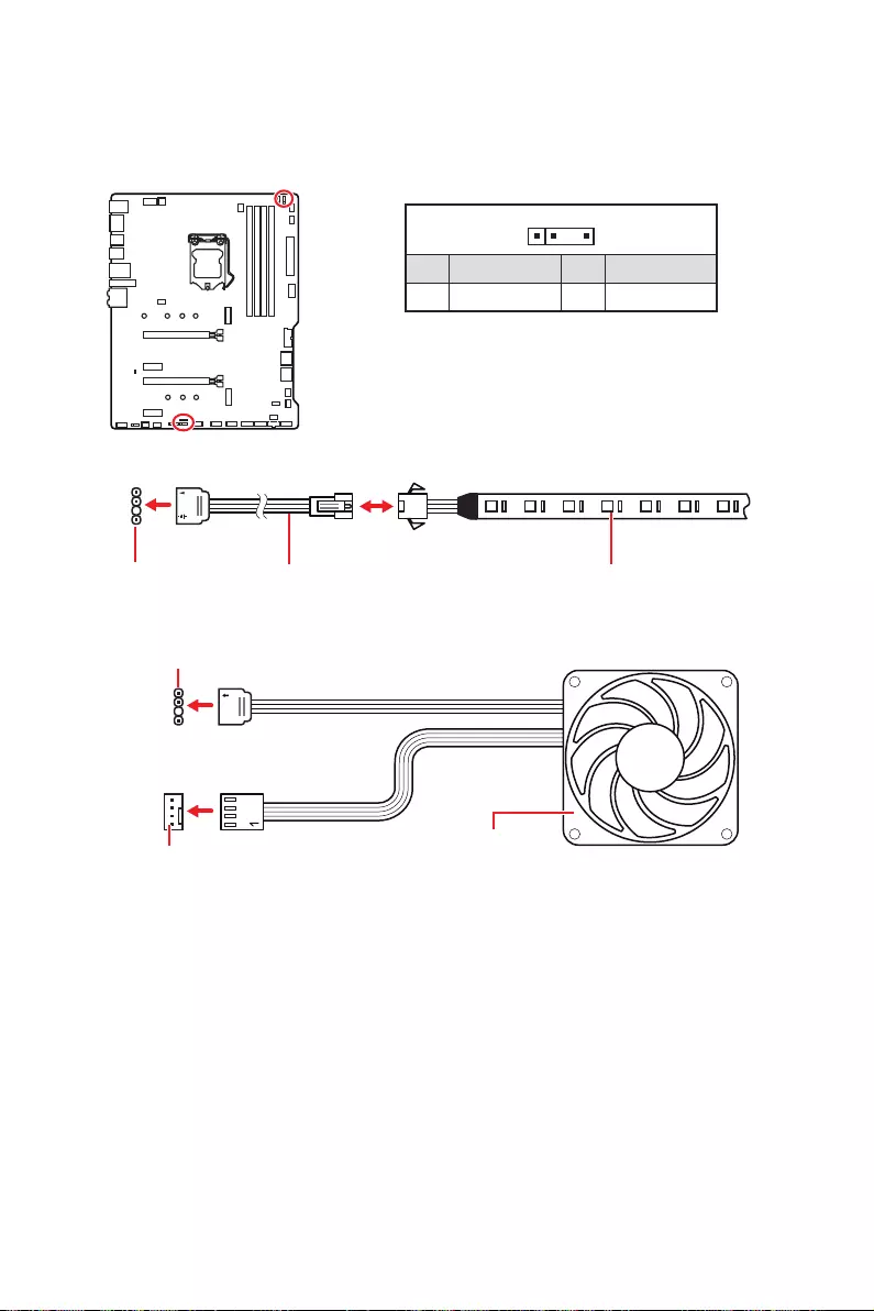
30 Компоненты материнской платы
1
1
1
D
+5V
⚠
ВНИМАНИЕ!
⚠
Внимание!
∙
∙
∙
JRAINBOW1~2: Разъемы адресных RGB LED
JRAINBOW
1
1 +5V 2 Data
3 No Pin 4 Ground
Подключение адресных RGB светодиодных лент
Подключение вентиляторов с адресной RGB светодиодной подсветкой
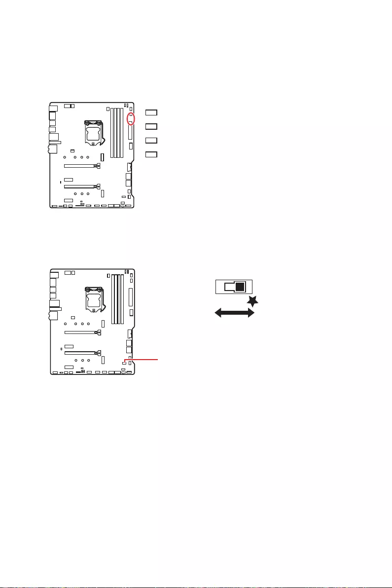
31
Встроенные индикаторы
Встроенные индикаторы
Индикаторы отладки EZ
CPU
DRAM
VGA
BOOT
LED_SW1: Переключатель для управления индикаторами EZ
LED_SW1
LED_OFF LED_ON

32 Установка ОС, драйверов и утилит
Установка ОС, драйверов и утилит
Установка Windows® 10
1.
2.
Windows® 10.
3. Restart
4. F11
5.
6. Press any
key to boot from CD or DVD…
7.
Установка драйверов
1.
2.
3. Select to choose what happens with this disc
Run DVDSetup.exe
DVDSetup.exe
MSI Driver Disc.
4.
Drivers/Software.
5. Install
6.
7. OK
8.
Установка утилит
1.
2. Utilities.
3.
4. Install
5.
6. OK
7. .

33
UEFI BIOS
UEFI BIOS
⚠
Внимание!
Преимущества UEFI
∙
∙
∙
∙
∙
∙
В следующих случаях система несовместима с архитектурой UEFI
∙ 32-битная ОС Windows
∙ Видеокарта устаревшего поколения
There is
no GOP (Graphics Output protocol) support detected in this graphics card
⚠
Внимание!
Как проверить режим BIOS?
Температура процессора:
Температура материнской
платы:
VCore:
Напряжение DDR:
Режим BIOS: UEFI
Режим загрузки UEFI

34 UEFI BIOS
Настройка BIOS
всегда устанавливайте настройки по умолчанию
⚠
Внимание!
∙
HELP.
∙
∙
Вход в настройки BIOS
DeletePress DEL key to
enter Setup Menu, F11 to enter Boot Menu
Функциональные клавиши
F1
F2
F3
F4
F5
F6
F7
F8
F9
F10
F12
Ctrl+F

35
UEFI BIOS
Сброс BIOS
∙F6
∙очистки данных CMOS
⚠
Внимание!
очистки данных CMOS.
Обновление BIOS
Обновление BIOS при помощи M-FLASH
1.
2.
▪Ctrl+F5
Yes
▪Del
M-FLASH
Yes
3.
4. Yes
BIOS.
5.

36 UEFI BIOS
Обновление BIOS при помощи MSI DRAGON CENTER
1.
Support.
2. Live Update
3. Scan
4. Download
5. NextIn Windows mode
NextStart
6.
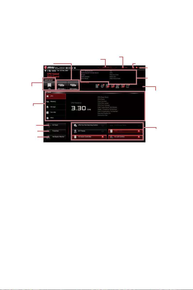
37
UEFI BIOS
Режим EZ
Переключатель
режимов установкиF7.
GAME BOOST
∙GAME BOOST
⚠
Внимание!
GAME BOOST
∙ Профиль XMP
∙ Переключатель режимов установкиF7,
∙ СкриншотF12
∙ ПоискCtrl + F
⚠
Внимание!

38 UEFI BIOS
∙ Язык
∙ Информация о системе
∙ Приоритет загрузочных устройств
∙ Информация о компонентахCPU, Memory, Storage, Fan
InfoHelp
∙ Функциональные клавиши
ON
⚠
Внимание!
∙M-FlashM-Flash
∙ Аппаратный мониторингаппаратного
мониторинга
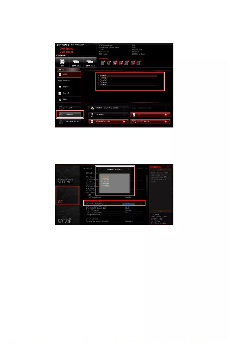
39
UEFI BIOS
∙ ИзбранноеF3
Избранное
▪ Добавление пункта BIOS в меню Избранное
1.
2. F2.
3. OK.

40 UEFI BIOS
▪ Удаление пункта BIOS из меню Избранное
1.
2. F2.
3. DeleteOK.

41
UEFI BIOS
Режим разгона
переключатель режимов установкиF7
BIOS
BIOS
∙ Выбор меню BIOS
▪SETTINGS
▪OC
▪M-FLASH
▪OC PROFILE
▪HARDWARE MONITOR
▪BOARD EXPLORER
∙ Экран меню

42 UEFI BIOS
Меню OC
⚠
Внимание!
∙
∙
∙
GAME BOOST.
∙
▶OC Explore Mode [Expert]
▶CPU Ratio Apply Mode [All Core]*
Turbo Boost.
▶CPU Ratio [Auto]
CPU Ratio Apply ModeAll Core.
▶X-Core Ratio Limit [Auto]
CPU Ratio Apply Mode
Turbo Ratio.
▶Numbers of CPU Cores of Group X [Auto]*
CPU Ratio Apply ModeTurbo Ratio.
▶Target CPU Turbo Ratio Group X [Auto]
CPU Ratio Apply Mode
Turbo Ratio.
▶Adjusted CPU Frequency

43
UEFI BIOS
▶Core X X of X xxxx MHz [Auto]
CPU Ratio Apply Mode
Per Core.
▶ Turbo Ratio Oset Value [Auto]
CPU Ratio Apply ModeTurbo Ratio Offset.
▶CPU Ratio Mode [Dynamic Mode]*
▶ CPU Ratio Oset When Running AVX [Auto]
▶Ring Ratio [Auto]
▶Adjusted Ring Frequency
▶GT Ratio [Auto]
▶Adjusted GT Frequency
▶+Misc Setting*
▶CPU Base Clock (MHz) [Default]

44 UEFI BIOS
▶CPU Base Clock Apply Mode [Auto]*
▶Clockgen Features sub-menu
Enter
▶ Extreme Memory Prole (XMP) [Disabled]
XMP.
▶DRAM Reference Clock [Auto]*
▶DRAM Frequency [Auto]
▶Adjusted DRAM Frequency
▶Load Memory Presets [Disabled]*
▶Memory Try It ! [Disabled]
▶DRAM Timing Mode [Link]
▶ Advanced DRAM Conguration
Enter

45
UEFI BIOS
▶Memory Fast Boot [Auto] *
▶DigitALL Power sub-menu
Enter
▶CPU Core/ GT Voltage Mode [Auto]*
▶CPU Core Voltage Mode [Auto]*
▶CPU Voltages control [Auto]
Auto
▶DRAM Voltages control [Auto]
Auto
▶PCH Voltages control [Auto]
Auto
▶CPU Memory Changed Detect [Enabled]*
▶OC Quick View Timer [3 Sec]*

46 UEFI BIOS
▶ CPU Specications sub-menu
Enter
▶MEMORY-Z sub-menu
Enter
▶CPU Features sub-menu
Enter
i
Regulatory Notices
Regulatory Notices
FCC Compliance Statement
Note: This equipment has been tested and found to
comply with the limits for a Class B digital device,
pursuant to part 15 of the FCC Rules. These limits are
designed to provide reasonable protection against
harmful interference in a residential installation. This
equipment generates, uses and can radiate radio
frequency energy and, if not installed and used in
accordance with the instructions, may cause harmful
interference to radio communications. However, there
is no guarantee that interference will not occur in a
particular installation. If this equipment does cause
harmful interference to radio or television reception,
which can be determined by turning the equipment
off and on, the user is encouraged to try to correct the
interference by one or more of the following measures:
yReorient or relocate the receiving antenna.
yIncrease the separation between the equipment
and receiver.
yConnect the equipment into an outlet on a circuit
different from that to which the receiver is
connected.
yConsult the dealer or an experienced radio/TV
technician for help.
Caution: Changes or modifications not expressly
approved by the party responsible for compliance could
void the user’s authority to operate the equipment.
Tested to comply with FCC standards
FOR HOME OR OFFICE USE
This device complies with part 15 of the FCC Rules.
Operation is subject to the following two conditions:
(1) This device may not cause harmful interference,
and (2) this device must accept any interference
received, including interference that may cause
undesired operation.
CE Conformity
Products bearing the CE marking comply
with one or more of the following EU
Directives as may be applicable:
RED 2014/53/EU; Low Voltage Directive 2014/35/EU;
EMC Directive 2014/30/EU; RoHS Directive 2011/65/EU.
Compliance with these directives is assessed using
applicable European Harmonized Standards.
The point of contact for regulatory matters is MSI,
B급 기기 (가정용 방송통신기자재)
クラスB情報技術装置
VCCI-B
C-Tick Compliance
Battery Information
European Union:
Batteries, battery packs, and
accumulators should not be disposed of as
unsorted household waste. Please use the
public collection system to return, recycle,
or treat them in compliance with the local
regulations.
Taiwan:
For better environmental protection,
waste batteries should be collected
separately for recycling or special
disposal.
California, USA:
The button cell battery may contain
perchlorate material and requires special
handling when recycled or disposed of in
California.
For further information please visit:
http://www.dtsc.ca.gov/hazardouswaste/perchlorate/
CAUTION: There is a risk of explosion, if battery is
incorrectly replaced.
Replace only with the same or equivalent type
recommended by the manufacturer.
Chemical Substances Information
In compliance with chemical substances regulations,
such as the EU REACH Regulation (Regulation EC
No. 1907/2006 of the European Parliament and the
Council), MSI provides the information of chemical
substances in products at:
http://www.msi.com/html/popup/csr/evmtprtt_pcm.
html
Environmental Policy
yThe product has been designed to
enable proper reuse of parts and
recycling and should not be thrown
away at its end of life.
yUsers should contact the local
authorized point of collection for recycling and
yVisit the MSI website and locate a nearby distributor
for further recycling information.
yUsers may also reach us at gpcontdev@msi.com for
Recycling, and Disassembly of MSI products.
WEEE (Waste Electrical and
Electronic Equipment) Statement
ENGLISH
To protect the global environment and as
an environmentalist, MSI must remind
you that…
Under the European Union (“EU”) Directive
on Waste Electrical and Electronic
Equipment, Directive 2002/96/EC, which
takes effect on August 13, 2005, products of “electrical

ii Regulatory Notices
and electronic equipment” cannot be discarded as
municipal wastes anymore, and manufacturers of
covered electronic equipment will be obligated to take
back such products at the end of their useful life. MSI
will comply with the product take back requirements
into the EU. You can return these products to local
collection points.
DEUTSCH
Hinweis von MSI zur Erhaltung und Schutz unserer
Umwelt
Altgeräte nicht mehr als kommunale Abfälle entsorgt
und Recyclingunternehmen beauftragt, die in die
Europäische Union in Verkehr gebrachten Produkte,
am Ende seines Lebenszyklus zurückzunehmen.
Bitte entsorgen Sie dieses Produkt zum gegebenen
Zeitpunkt ausschliesslich an einer lokalen
Altgerätesammelstelle in Ihrer Nähe.
FRANÇAIS
En tant qu’écologiste et afin de protéger
l’environnement, MSI tient à rappeler ceci…
Au sujet de la directive européenne (EU) relative aux
déchets des équipement électriques et électroniques,
directive 2002/96/EC, prenant effet le 13 août 2005, que
les produits électriques et électroniques ne peuvent
être déposés dans les décharges ou tout simplement
mis à la poubelle. Les fabricants de ces équipements
seront obligés de récupérer certains produits en fin
de vie. MSI prendra en compte cette exigence relative
au retour des produits en fin de vie au sein de la
communauté européenne. Par conséquent vous pouvez
retourner localement ces matériels dans les points
de collecte.
РУССКИЙ
ESPAÑOL
MSI como empresa comprometida con la protección
del medio ambiente, recomienda:
Bajo la directiva 2002/96/EC de la Unión Europea
en materia de desechos y/o equipos electrónicos,
con fecha de rigor desde el 13 de agosto de 2005,
los productos clasificados como “eléctricos y
equipos electrónicos” no pueden ser depositados
en los contenedores habituales de su municipio, los
fabricantes de equipos electrónicos, están obligados
a hacerse cargo de dichos productos al termino de
su período de vida. MSI estará comprometido con los
términos de recogida de sus productos vendidos en
la Unión Europea al final de su periodo de vida. Usted
debe depositar estos productos en el punto limpio
establecido por el ayuntamiento de su localidad o
entregar a una empresa autorizada para la recogida de
estos residuos.
NEDERLANDS
Om het milieu te beschermen, wil MSI u eraan
herinneren dat….
De richtlijn van de Europese Unie (EU) met betrekking
tot Vervuiling van Electrische en Electronische
producten (2002/96/EC), die op 13 Augustus 2005 in
zal gaan kunnen niet meer beschouwd worden als
vervuiling. Fabrikanten van dit soort producten worden
verplicht om producten retour te nemen aan het
eind van hun levenscyclus. MSI zal overeenkomstig
de richtlijn handelen voor de producten die de
merknaam MSI dragen en verkocht zijn in de EU. Deze
goederen kunnen geretourneerd worden op lokale
inzamelingspunten.
SRPSKI
vas podesti da…
EC, koja stupa na snagu od 13. Avgusta 2005, proizvodi
proizvoda kojima je istekao vek trajanja, koji imaju MSI
vratiti na lokalnim mestima za prikupljanje.
POLSKI
odpadów produktów elektrycznych i elektronicznych
(sprzedawane na terenie Unii Europejskiej) wycofywane
wyznaczonych punktach zbiorczych.
TÜRKÇE

iii
Regulatory Notices
ČESKY
EC platné od 13. srpna 2005 je zakázáno likvidovat
komunálním odpadu a výrobci elektronických
MAGYAR
Annak érdekében, hogy környezetünket megvédjük,
Önt, hogy …
hulladékairól szóló 2002/96/EK irányelve szerint
az elektromos és elektronikus berendezések
és az ilyen elektronikus berendezések gyártói
kötelessé válnak az ilyen termékek visszavételére
azok hasznos élettartama végén. Az MSI betartja a
termékvisszavétellel kapcsolatos követelményeket
termékek esetében, azok élettartamának végén. Az
ITALIANO
Per proteggere l’ambiente, MSI, da sempre amica della
natura, ti ricorda che….
In base alla Direttiva dell’Unione Europea (EU) sullo
Smaltimento dei Materiali Elettrici ed Elettronici,
Direttiva 2002/96/EC in vigore dal 13 Agosto 2005,
prodotti appartenenti alla categoria dei Materiali
Elettrici ed Elettronici non possono più essere eliminati
come rifiuti municipali: i produttori di detti materiali
saranno obbligati a ritirare ogni prodotto alla fine
del suo ciclo di vita. MSI si adeguerà a tale Direttiva
ritirando tutti i prodotti marchiati MSI che sono stati
venduti all’interno dell’Unione Europea alla fine del
loro ciclo di vita. È possibile portare i prodotti nel più
vicino punto di raccolta
日本JIS C 0950材質宣言
http://www.msi.com/html/popup/csr/cemm_jp.html
http://tw.msi.com/html/popup/csr_tw/cemm_jp.html
India RoHS
(Management and Handling) Rule 2011” and prohibits
use of lead, mercury, hexavalent chromium,
polybrominated biphenyls or polybrominated diphenyl
ethers in concentrations exceeding 0.1 weight % and
0.01 weight % for cadmium, except for the exemptions
set in Schedule 2 of the Rule.
Türkiye EEE yönetmeliği
Україна обмеження на наявність
небезпечних речовин
Việt Nam RoHS
Wireless Radio Use
This device is restricted to indoor use when operating
in the 2.4GHz, 5GHz frequency band.
Cet appareil doit être utilisé à l’intérieur.
NCC無線設備警告聲明
Products with radio functionality (EMF)
This product incorporates a radio transmitting
and receiving device. For computers in normal
use, a separation distance of 20 cm ensures that
radio frequency exposure levels comply with EU
requirements. Products designed to be operated
at closer proximities, such as tablet computers,
comply with applicable EU requirements in typical
operating positions. Products can be operated without
maintaining a separation distance unless otherwise
indicated in instructions specific to the product.
Restrictions for products with radio functionality
CAUTION: IEEE 802.11x wireless LAN with
5.15–5.35 GHz frequency band is restricted
for indoor use only in all European Union
member states, EFTA (Iceland, Norway,
Liechtenstein), and most other European countries
(e.g., Switzerland, Turkey, Republic of Serbia).
Using this WLAN application outdoors might lead to
interference issues with existing radio services.
Radio frequency bands and maximum power levels
Features :802.11 a/b/g/n/ac, BT
Frequency Range :2.4GHz, 5GHz
Modulation :FHSS, DSSS, OFDM
Power Output :10, 20, 23
Channel Band Width :1, 5, 20 ,40 , 80MHz
iv Regulatory Notices
MS-7C79主板产品中有害物质的名称及含量
(Pb)
(Hg)
(Cd)
(Cr(VI))
(PBB)
(PBDE)
限用物質含有情況標示聲明書
(Pb)
(Hg)
(Cd)
(Cr+6)
(PBB)
(PBDE)
Copyright
Copyright © 2020 All rights reserved.
The MSI logo used is a registered trademark of
mentioned may be trademarks of their respective
owners. No warranty as to accuracy or completeness is
expressed or implied. MSI reserves the right to make
changes to this document without prior notice.
Revision History
Version 1.0, 2020/03, First release.
Technical Support
If a problem arises with your system and no solution
can be obtained from the user guide, please
contact your place of purchase or local distributor.
Alternatively, please try the following help resources
for further guidance.
yVisit the MSI website for technical guide, BIOS
updates, driver updates, and other information:
http://www.msi.com
yRegister your product at: http://register.msi.com
MSI
Loading…
M
- Modern MD272PW
- Modern MD272QP
- Modern MD272QPW
- Monitor
- Monitor MSI Mag Artymis 324CP
- Monitor MSI MPG Artymis
- Monitor MSI MPG Artymis 323CQR
- Monitor MSI MPG Artymis 343CQR 34″» 3440x1440px 165Hz 1 ms Curved
- Monitor MSI Oculux NXG253R
- MP11B2
- MP221
- MP241
- MP54G3
- MP54G4 (MS-6833A)
- MP54G54
- MP54G5 (MS-6833B)
- MP54G-BT
- MP54GBT2
- MPC 4002
- MPC 6512
- MPC 8652
- MPC 865 PRO
- MPG27C2
- MPG27CQ2
- MPG27CQ22
- MPG341CQR3
- MPG341CQRV
- MPG Artymis
- MPG B460I Gaming Edge WIFI2
- MPG B5502
- MPG B550 Gaming carbon WIFI
- MPG B550 Gaming Edge WIFI2
- MPG B550 Gaming Plus
- MPG B550I Gaming Edge WIFI2
- MPG GUNGNIR 100
- MPG GUNGNIR 100D
- MPG Gungnir 100P3
- MPG Sekira 100R
- MPG Sekira 500P
- MPG TRIDENT 3 10SC-064DE
- MPG TRIDENT 3 10SI-067DE
- MPG TRIDENT 3 10SI-069DE
- MPG X5702
- MPG X570 Gaming Edge WIFI
- MPG X570 Gaming Plus2
- MPG Z3902
- MPG Z390 GAMING EDGE AC
- MPG Z390 GAMING PLUS
- MPG Z390 Gaming Pro carbon3
- MPG Z390 GAMING PRO CARBON AC
- MPG Z390I Gaming Edge AC2
- MPG Z390M GAMING EDGE AC2
- MPG Z490
- MPG Z490 GAMING CARBON WIFI2
- MPG Z490 Gaming Edge WiFi2
- MPG Z490 GAMING PLUS4
- MPG Z490M Gaming Edge WiFi2
- MPG Z5902
- MS-10022
- MS-1003
- MS-1004
- MS-1006
- MS-1010
- MS-1011
- MS-10123
- MS 1012 — 12.1
- MS-10132
- MS-1016
- MS-10223
- MS-1029
- MS-10342
- MS-10352
- MS-10371
- MS-10392
- MS-10472
- MS-10572
- MS-10581
- MS-12211
- MS-1221 — 12.1″» — 0 MB Ram
- MS-12221
- MS-13311
- MS-133312
- MS-1351
- MS-1352
- MS-13552
- MS-1355 V1.023
- MS-1412
- MS-14141
- MS-1421
- MS-1422
- MS-14513
- MS-14521
- MS-1454
- MS-14571
- MS-14B3
- MS-16332
- MS 7005 — 651M-L Motherboard — Micro ATX
- MS 7030 — K8N Neo Platinum Motherboard
- MS — 9211
- MS N913
Loading…
Loading…
Nothing found
MPG Z490 GAMING PLUS
Product Data Sheet
1 pgs1.48 Mb0
User Manual
234 pgs12.3 Mb0
User manual
196 pgs10.08 Mb0
User Manual
76 pgs4.88 Mb1
Table of contents
Loading…
…
MSI User manual
Download
Specifications and Main Features
Frequently Asked Questions
User Manual

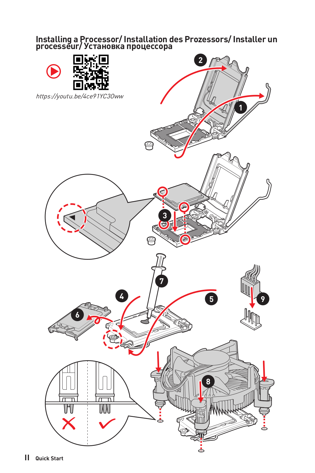
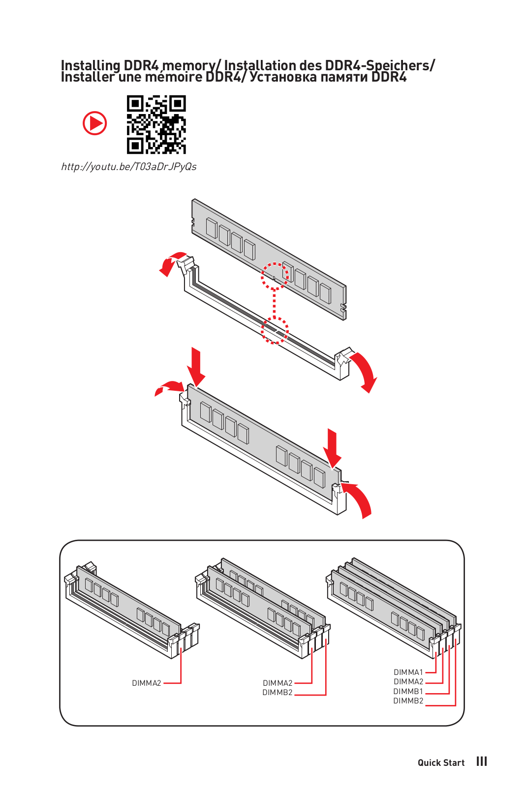
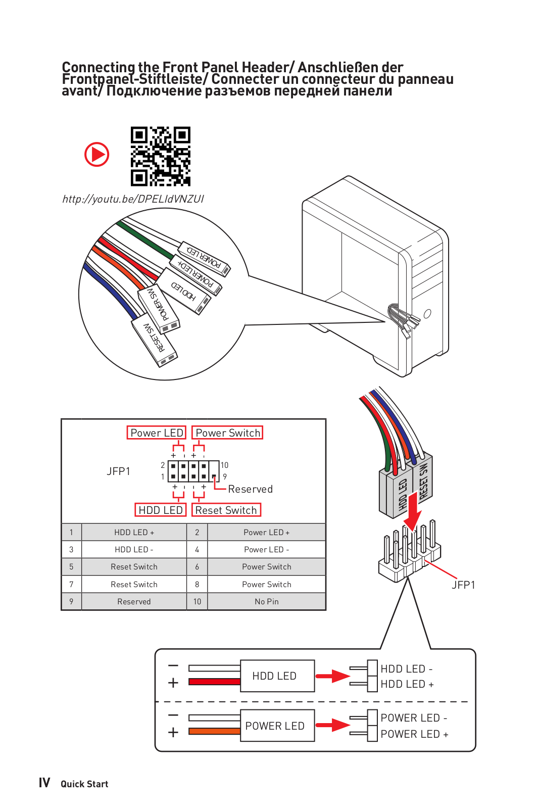
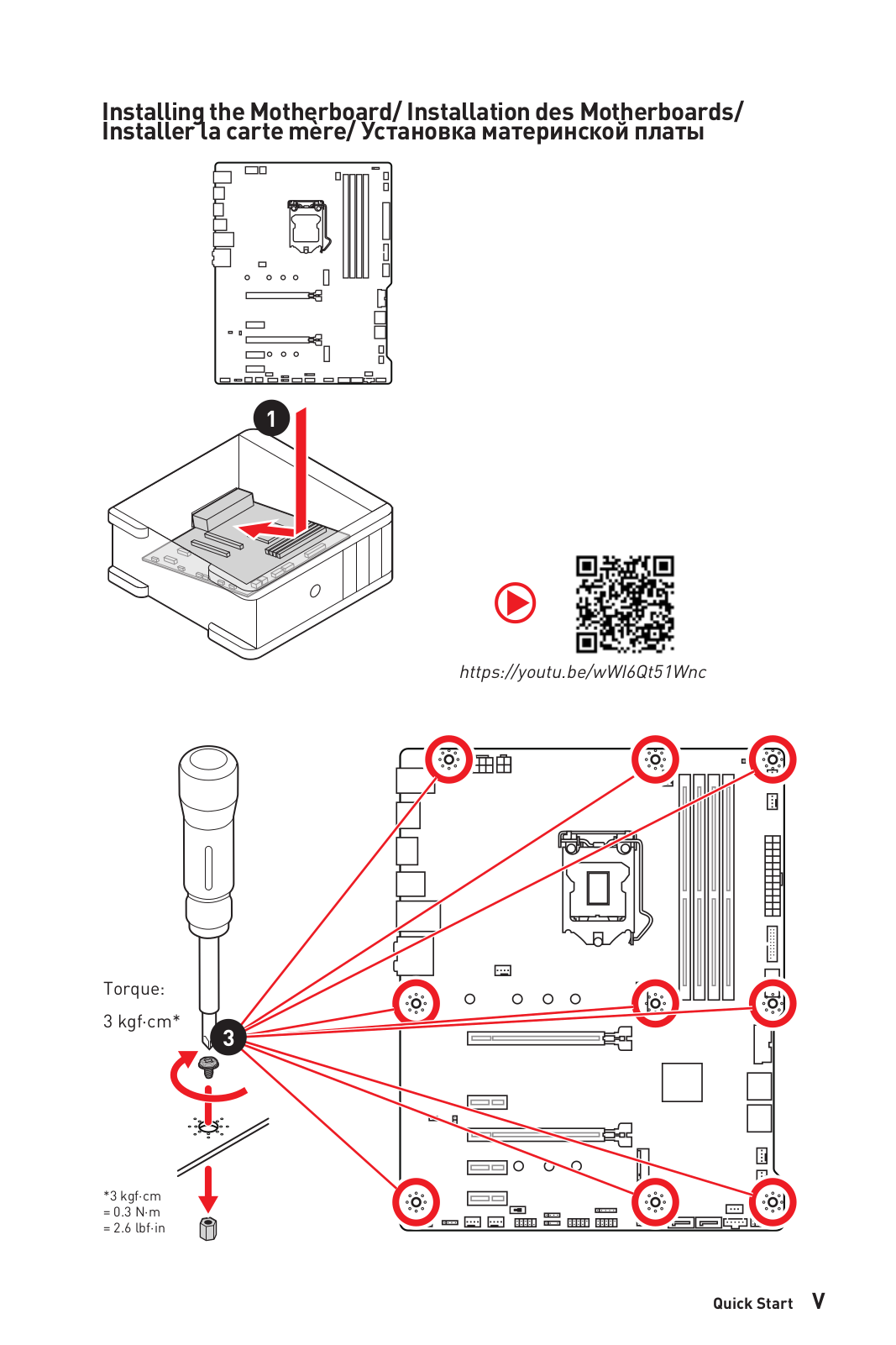
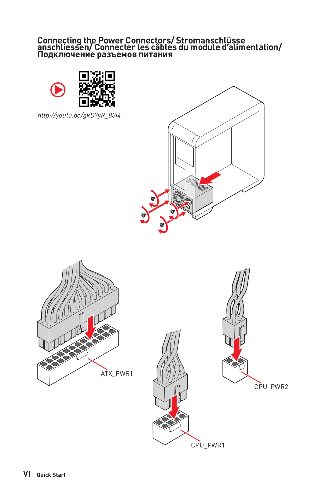
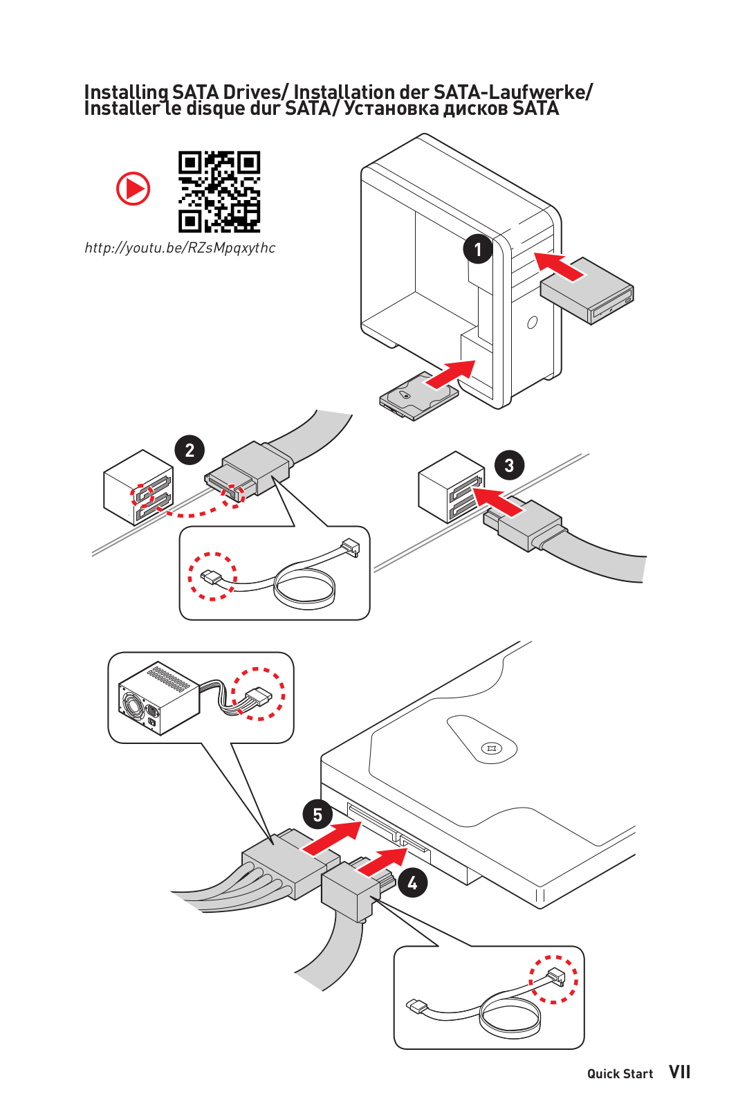
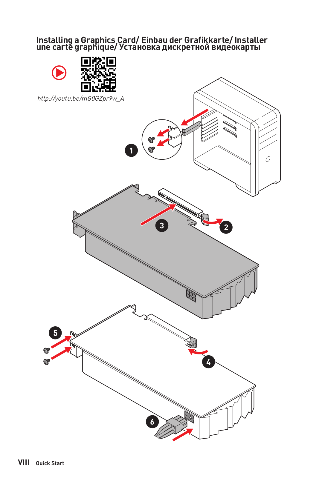
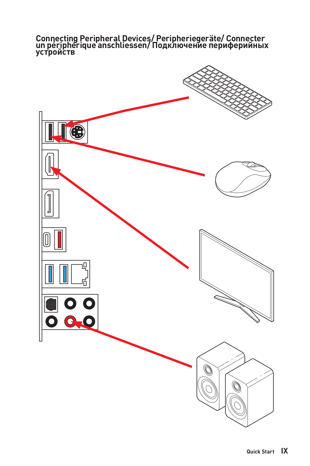
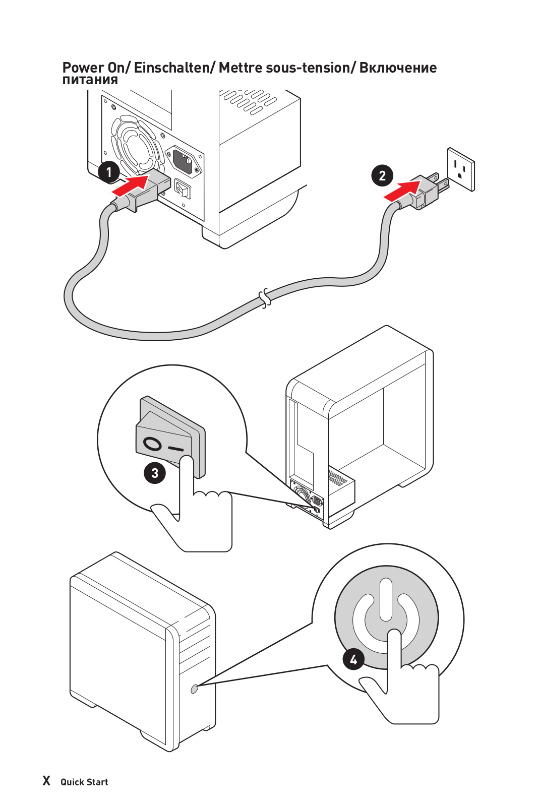
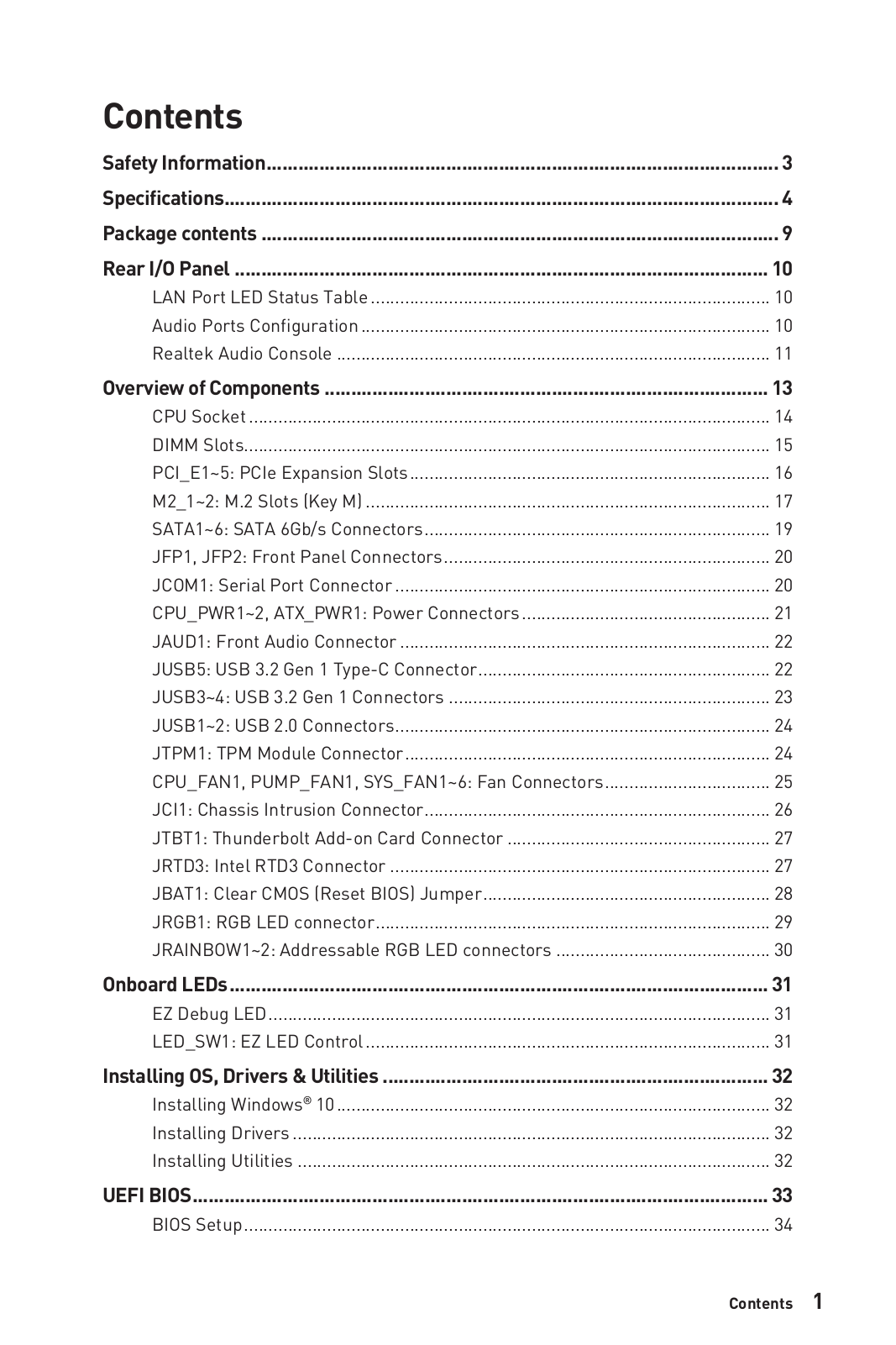

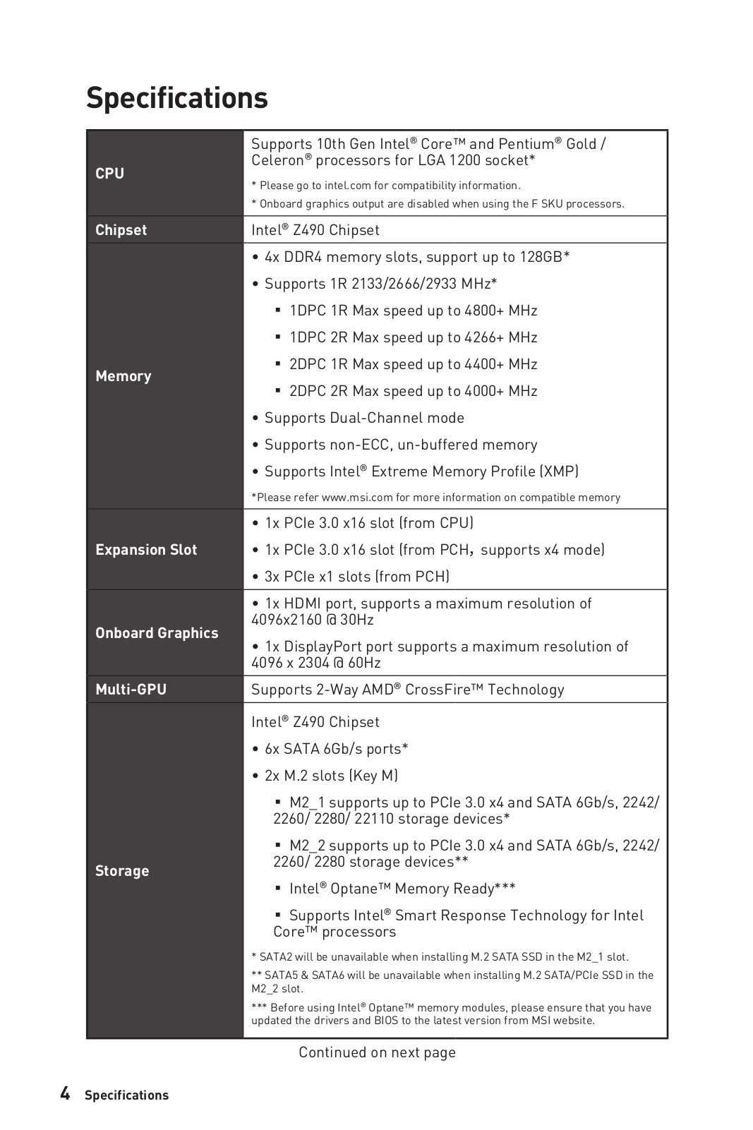
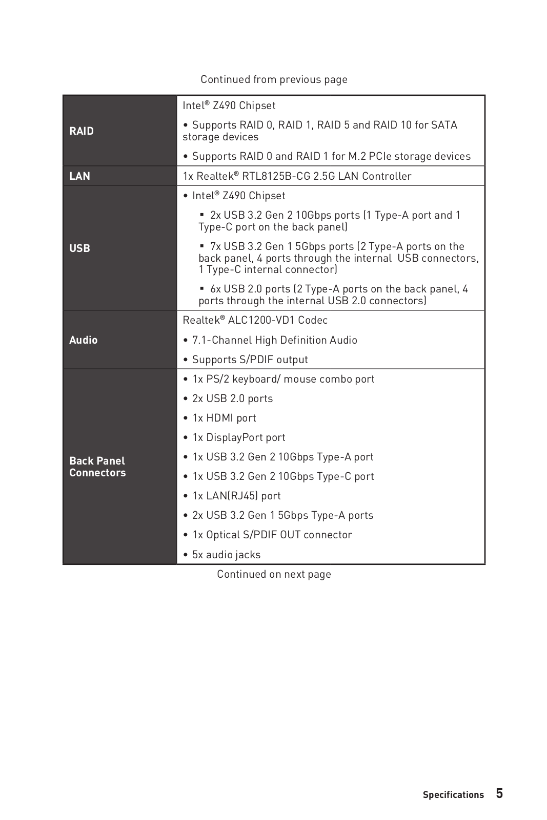
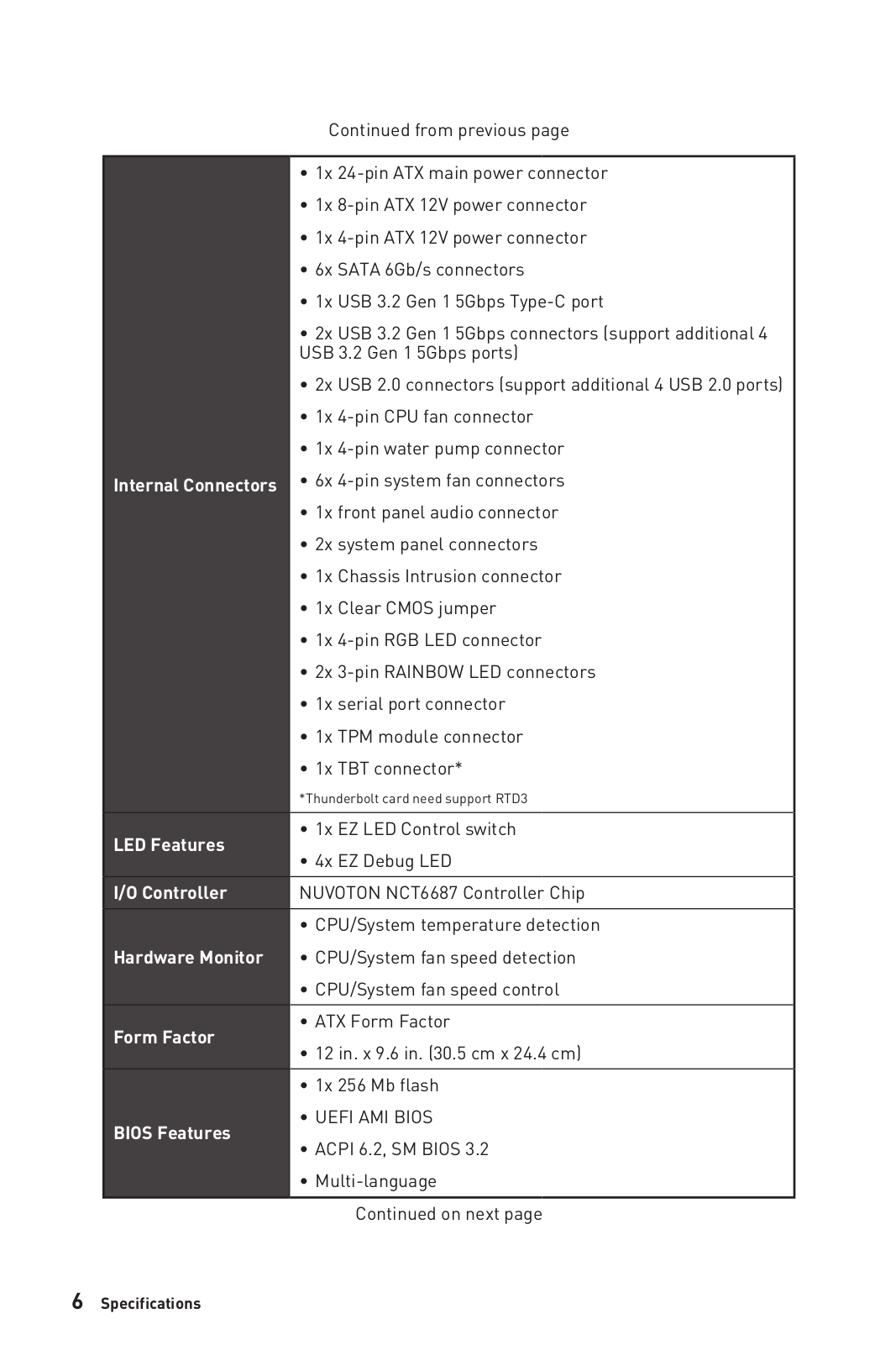
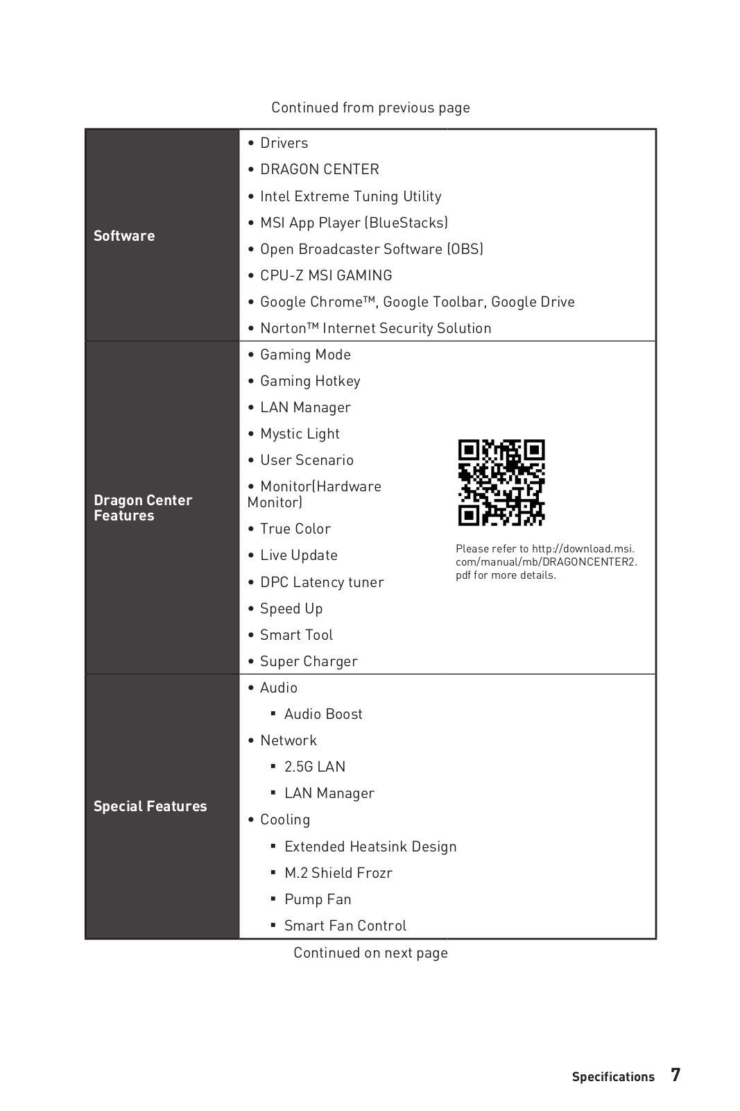
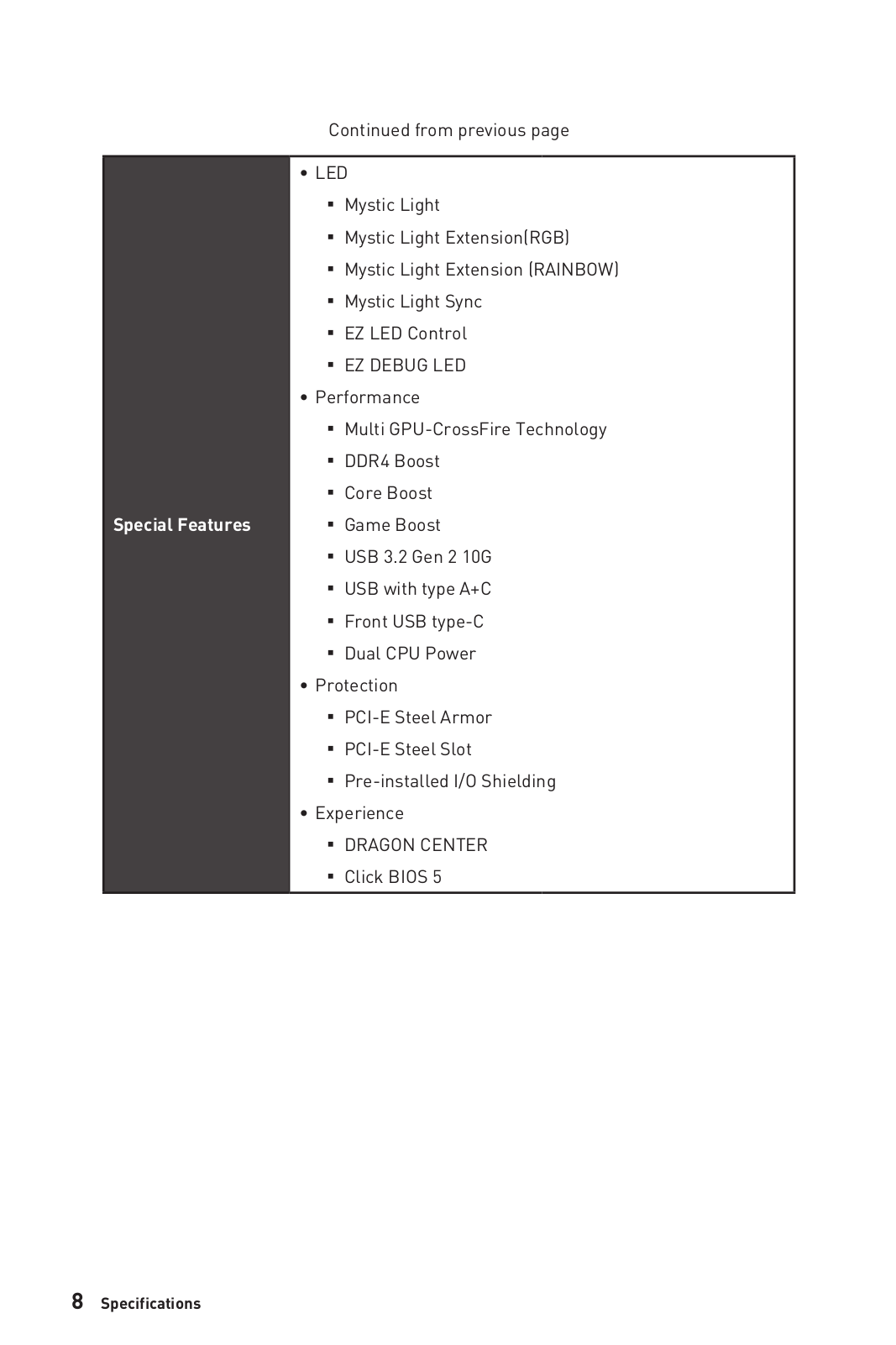
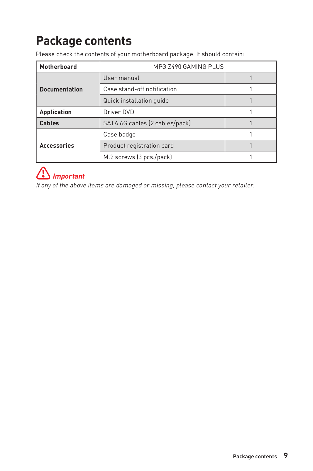
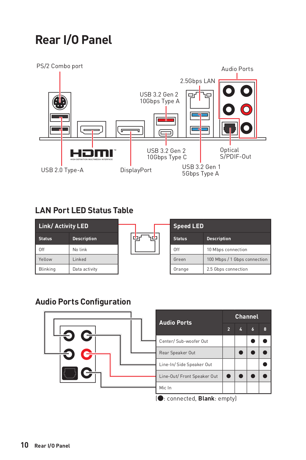
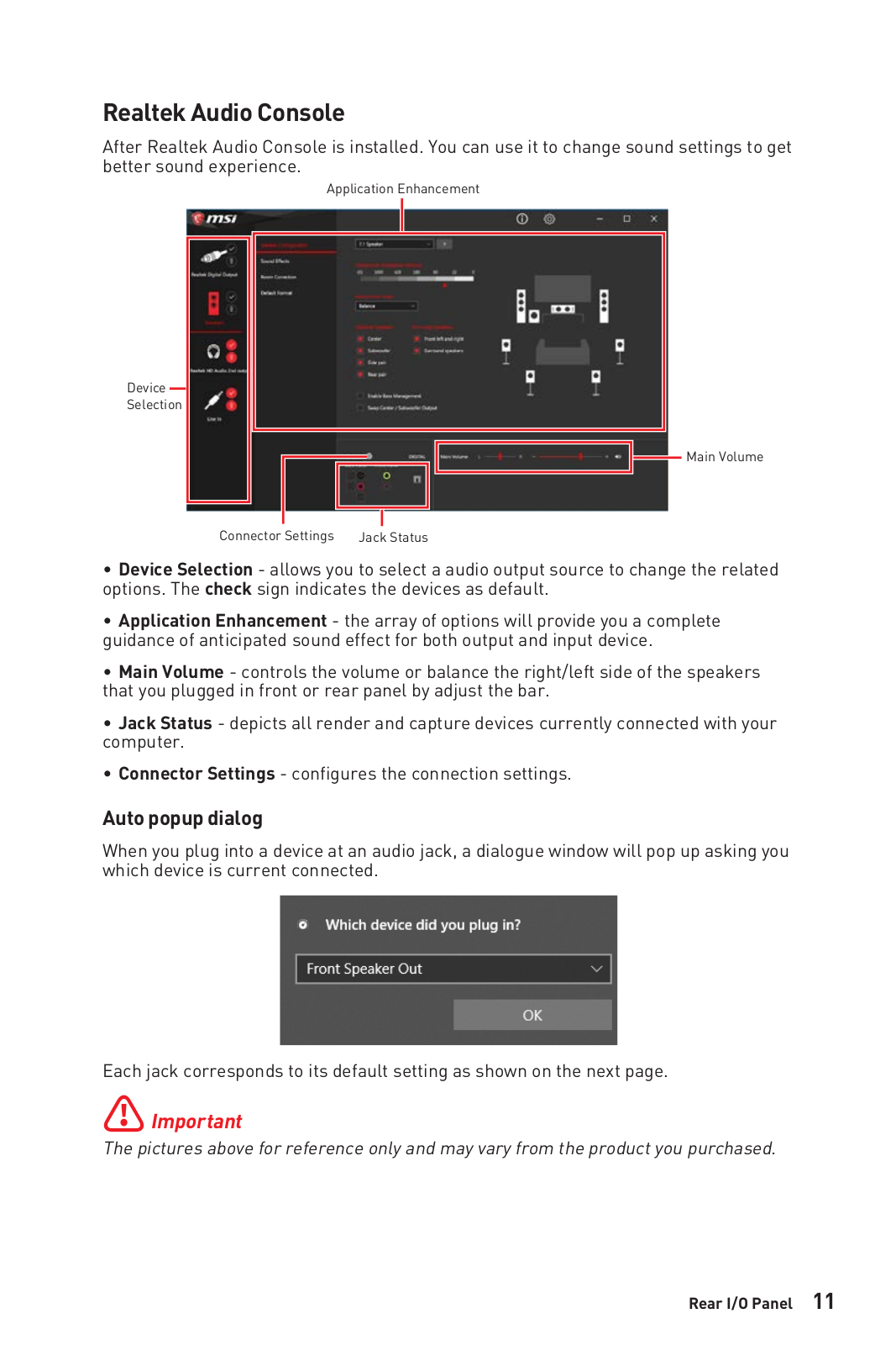

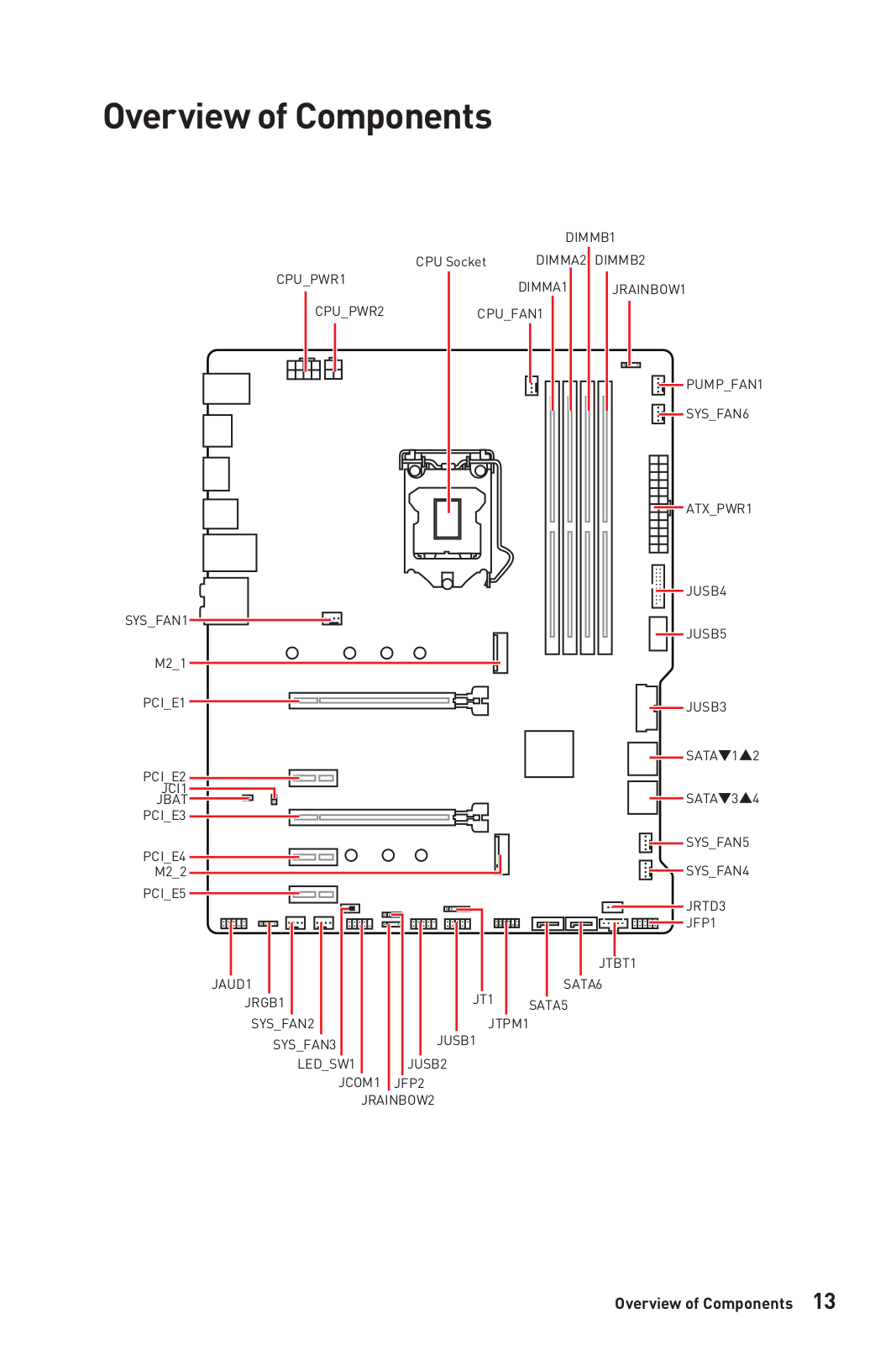


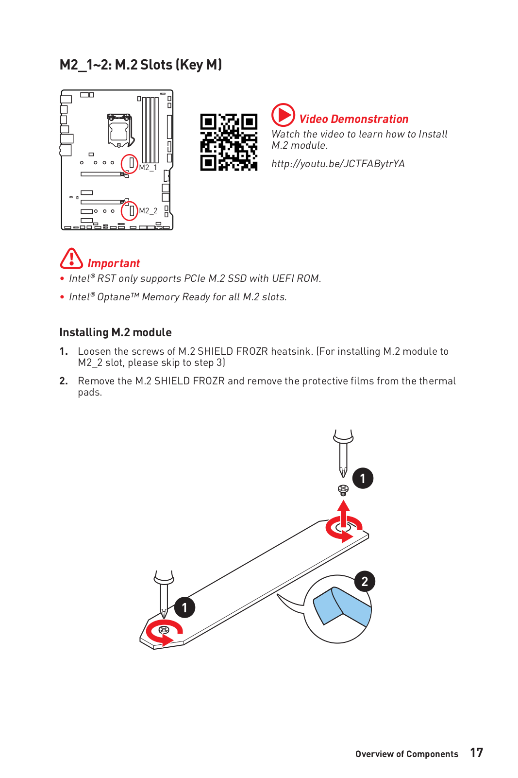

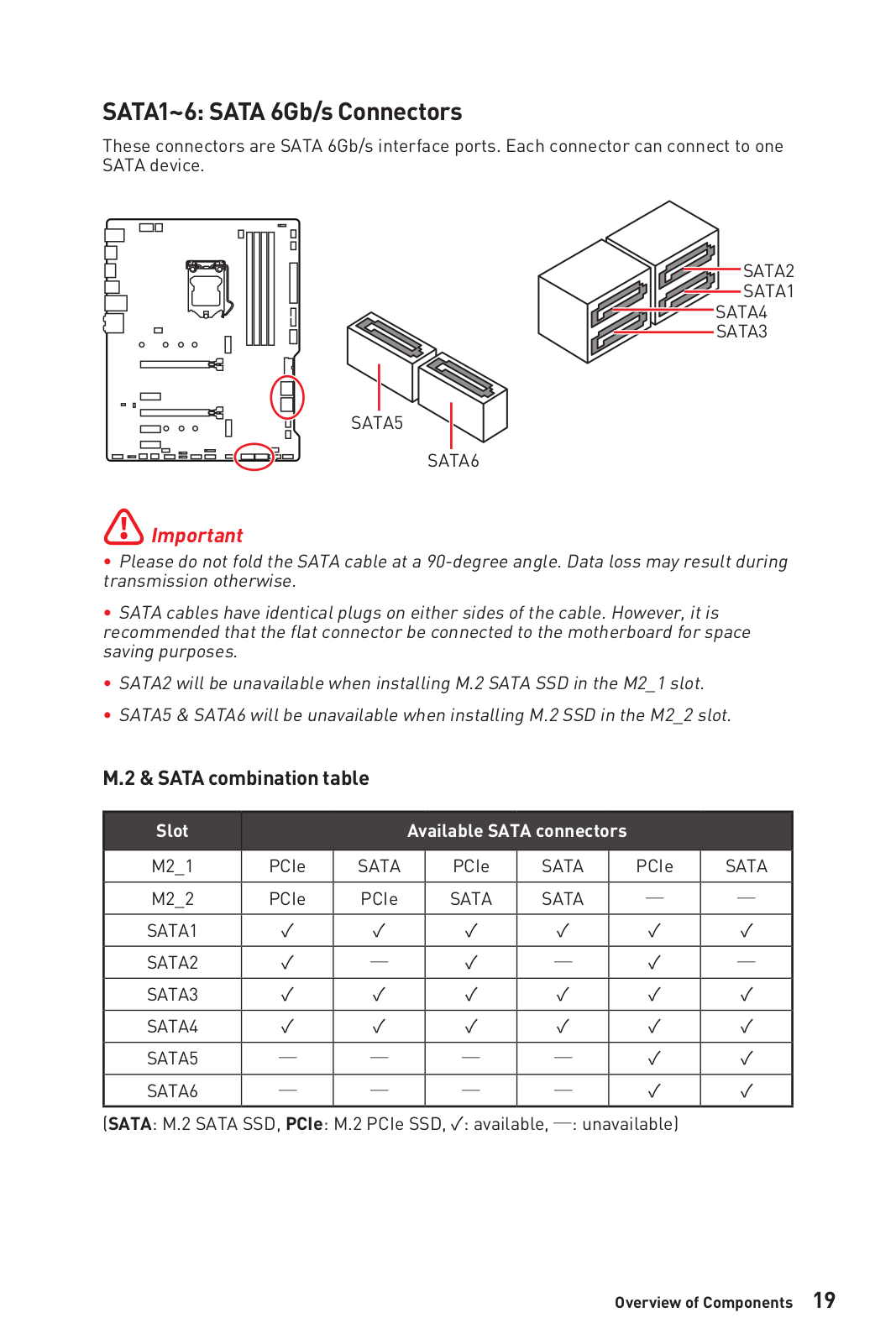
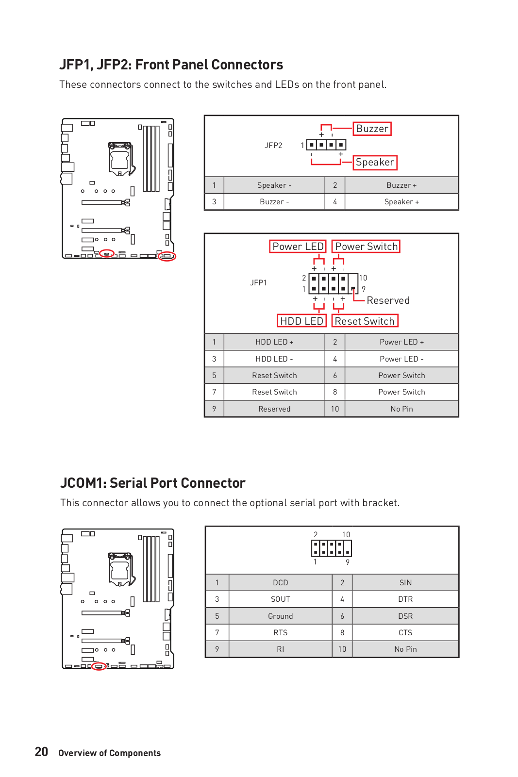
Loading…
+ 166 hidden pages
You need points to download manuals.
1 point = 1 manual.
You can buy points or you can get point for every manual you upload.
Buy points
Upload your manuals
View the manual for the MSI MPG Z490 GAMING PLUS here, for free. This manual comes under the category motherboards and has been rated by 6 people with an average of a 7.9.
This manual is available in the following languages: English. Do you have a question about the MSI MPG Z490 GAMING PLUS or do you need help?
Ask your question here
MSI MPG Z490 GAMING PLUS specifications
Below you will find the product specifications and the manual specifications of the MSI MPG Z490 GAMING PLUS.
The MSI MPG Z490 GAMING PLUS is an ATX form factor motherboard designed for use in PCs. It is compatible with Intel processors, specifically the Intel Core i9 series. The motherboard supports a maximum of one SMP processor.
With four DIMM memory slots, the MSI MPG Z490 GAMING PLUS allows for substantial memory expansion. Non-ECC memory is supported, which enhances system stability. The motherboard supports a wide range of memory clock speeds, ranging from 2133 MHz to 4800 MHz, offering flexibility in memory configuration. The maximum internal memory supported is 128 GB, providing ample capacity for demanding applications and multitasking.
In terms of expansion slots, the MSI MPG Z490 GAMING PLUS features two PCI Express x16 (Gen 3.x) slots and three PCI Express x1 slots. This enables the connection of multiple peripherals and expansion cards, such as graphics cards or networking devices.
Overall, the MSI MPG Z490 GAMING PLUS is a high-performance motherboard that offers excellent compatibility with Intel Core i9 processors. Its four DIMM memory slots and support for a wide range of memory clock speeds provide flexibility for memory expansion and configuration. The inclusion of multiple PCI Express slots allows for the addition of various expansion cards, enhancing the overall functionality of the PC.
Processor manufacturer
Intel
Supported memory types
DDR4-SDRAM
PCI Express x16 (Gen 3.x) slots
2
Supported storage drive types
HDD & SSD
Parallel processing technology support
2-Way SLI, 3-Way CrossFireX
General
| Brand | MSI |
| Model | MPG Z490 GAMING PLUS | MPG Z490 GAMING PLUS |
| Product | motherboard |
| EAN | 0824142212486, 4719072722005 |
| Language | English |
| Filetype | User manual (PDF) |
Features
| Component for | PC |
| Motherboard form factor | ATX |
| Motherboard chipset family | Intel |
| Audio chip | Realtek ALC1200 |
| Audio output channels | 7.1 channels |
| Cooling type | Passive |
| Power source type | ATX |
| Number of mounting holes | 9 |
| Windows operating systems supported | Windows 10 |
| Motherboard chipset | Intel Z490 |
Processor
| Processor manufacturer | Intel |
| Compatible processor series | Intel® Core™ i9 |
| Maximum number of SMP processors | 1 |
| Processor socket | LGA 1200 (Socket H5) |
Memory
| Supported memory types | DDR4-SDRAM |
| Number of memory slots | 4 |
| Memory slots type | DIMM |
| Memory channels | Dual-channel |
| Supported memory clock speeds | 2133,2400,2666,2933,3000,3200,3300,3333,3400,3466,3600,3733,3866,4000,4133,4200,4266,4300,4400,4800 MHz |
| Maximum internal memory | 128 GB |
| Unbuffered memory | Yes |
Expansion slots
| PCI Express x16 (Gen 3.x) slots | 2 |
| PCI Express x1 slots | 3 |
| Number of M.2 (M) slots | 2 |
Storage controllers
| Supported storage drive types | HDD & SSD |
| Supported storage drive interfaces | M.2, SATA |
| Number of HDDs supported | 6 |
| RAID levels | 0, 1,5, 10 |
Graphics
| Parallel processing technology support | 2-Way SLI, 3-Way CrossFireX |
| Maximum resolution | 4096 x 2304 pixels |
| DirectX version | 12.0 |
| Number of displays supported | 2 |
Weight & dimensions
Packaging content
| Cables included | SATA |
| Drivers included | Yes |
Rear panel I/O ports
| Headphone outputs | 1 |
| Microphone in | Yes |
| S/PDIF out port | Yes |
| Thunderbolt ports quantity | 1 |
| USB 3.2 Gen 1 (3.1 Gen 1) Type-C ports quantity | 1 |
| USB 2.0 ports quantity | 2 |
| USB 3.2 Gen 1 (3.1 Gen 1) Type-A ports quantity | 2 |
| USB 3.2 Gen 2 (3.1 Gen 2) Type-A ports quantity | 1 |
| USB 3.2 Gen 2 (3.1 Gen 2) Type-C ports quantity | 0 |
| Ethernet LAN (RJ-45) ports | 1 |
| eSATA ports quantity | 0 |
| PS/2 ports quantity | 1 |
| Firewire (IEEE 1394) ports | 0 |
| VGA (D-Sub) ports quantity | 0 |
| HDMI ports quantity | 1 |
| DVI-D ports quantity | 0 |
| DisplayPorts quantity | 1 |
| USB connector type | USB Type-A, USB Type-C |
Network
| Ethernet LAN | Yes |
| Ethernet interface type | 2.5 Gigabit Ethernet |
| LAN controller | Intel I219-V, Realtek RTL8125-CG |
| Wi-Fi | No |
| Wake-on-LAN ready | Yes |
BIOS
Internal I/O
| Number of SATA III connectors | 6 |
| USB 2.0 connectors | 2 |
| USB 3.2 Gen 1 (3.1 Gen 1) connectors | 1 |
| USB 3.2 Gen 2 (3.1 Gen 2) connectors | 0 |
| Number of SATA II connectors | 0 |
| Number of Parallel ATA connectors | 0 |
| Front panel audio connector | Yes |
| Front panel connector | Yes |
| ATX Power connector (24-pin) | Yes |
| Power fan connector | Yes |
| CPU fan connector | Yes |
| Number of chassis fan connectors | 6 |
| Chassis intrusion connector | Yes |
| Peripheral (Molex) power connectors (4-pin) | 1 |
| EPS power connector (8-pin) | Yes |
| TPM connector | Yes |
| Total number of SATA connectors | 6 |
Logistics data
| Harmonized System (HS) code | 84733020 |
show more
Frequently Asked Questions
Can’t find the answer to your question in the manual? You may find the answer to your question in the FAQs about the MSI MPG Z490 GAMING PLUS below.
Why is my computer not powering on when I press the power button?
Make sure all power connectors from the power supply are securely attached to the motherboard, including the main ATX power connector and the CPU power connector.
How can I connect my front panel buttons and LEDs to the motherboard?
Refer to the specific pin layout mentioned in the motherboard manual to correctly connect the front panel cables, ensuring that the power button, reset switch, HDD activity LED, and power LED are connected to their respective headers.
What should I do if my CPU temperatures are too high?
Ensure that the CPU cooler is properly installed, with a sufficient amount of thermal paste applied. Verify that the CPU fan is spinning and that there is proper airflow inside the computer case. You can also adjust the fan speeds and monitor temperatures using the smart BIOS settings.
How can I enable XMP (Extreme Memory Profile) for my RAM?
Access the BIOS settings by pressing the «Delete» key during startup. Navigate to the memory settings section and look for XMP or DOCP (Direct Over Clock Profile) options. Enable the XMP or DOCP profile that corresponds to your RAM specifications to achieve the advertised speeds.
I’m experiencing audio issues, what can I do?
Firstly, ensure that your speakers or headphones are properly connected to the correct audio jacks on the motherboard. You can try reinstalling the audio drivers specific to your operating system. Additionally, check the BIOS settings to ensure that the audio chipset is enabled and not muted.
Does the MSI MPG Z490 GAMING PLUS support Intel processors?
Yes, the MSI MPG Z490 GAMING PLUS is compatible with Intel processors. This means that users can choose from a range of Intel CPUs to use with this motherboard.
How many memory slots does the MSI MPG Z490 GAMING PLUS have?
The MSI MPG Z490 GAMING PLUS has 4 memory slots. This allows for a maximum of 128 GB of RAM to be installed, providing ample memory capacity for high-performance tasks.
Does the MSI MPG Z490 GAMING PLUS support non-ECC memory?
Yes, the MSI MPG Z490 GAMING PLUS supports non-ECC memory. This means that users can use both ECC and non-ECC memory modules with this motherboard.
How many PCI Express x16 slots does the MSI MPG Z490 GAMING PLUS have?
The MSI MPG Z490 GAMING PLUS has 2 PCI Express x16 slots. This provides ample room for high-performance graphics cards, allowing users to build powerful gaming rigs or workstations.
What types of storage drives are supported by the MSI MPG Z490 GAMING PLUS?
The MSI MPG Z490 GAMING PLUS supports both HDD and SSD storage drives. This provides users with flexibility in choosing their preferred storage solution, whether it be traditional hard drives or faster solid-state drives. Additionally, it supports both M.2 and SATA interfaces, further expanding the options for storage devices.
What is the width of the MSI MPG Z490 GAMING PLUS?
The MSI MPG Z490 GAMING PLUS has a width of — mm.
What is the depth of the MSI MPG Z490 GAMING PLUS?
The MSI MPG Z490 GAMING PLUS has a depth of — mm.
What type of USB connection does the MSI MPG Z490 GAMING PLUS have?
The MSI MPG Z490 GAMING PLUS has a USB Type-A, USB Type-C connection.
Is the manual of the MSI MPG Z490 GAMING PLUS available in English?
Yes, the manual of the MSI MPG Z490 GAMING PLUS is available in English .
Is your question not listed? Ask your question here
I
Quick Start
Quick Start
Thank you for purchasing the MSI® MPG Z490 GAMING EDGE WIFI
motherboard. This Quick Start section provides demonstration
diagrams about how to install your computer. Some of the
installations also provide video demonstrations. Please link to the
URL to watch it with the web browser on your phone or tablet. You
may have even link to the URL by scanning the QR code.
Kurzanleitung
Danke, dass Sie das MSI® MPG Z490 GAMING EDGE WIFI
Motherboard gewählt haben. Dieser Abschnitt der Kurzanleitung
bietet eine Demo zur Installation Ihres Computers. Manche
Installationen bieten auch die Videodemonstrationen. Klicken Sie
auf die URL, um diese Videoanleitung mit Ihrem Browser auf Ihrem
Handy oder Table anzusehen. Oder scannen Sie auch den QR Code
mit Ihrem Handy, um die URL zu öffnen.
Présentation rapide
Merci d’avoir choisi la carte mère MSI® MPG Z490 GAMING
EDGE WIFI. Ce manuel fournit une rapide présentation avec des
illustrations explicatives qui vous aideront à assembler votre
ordinateur. Des tutoriels vidéo sont disponibles pour certaines
étapes. Cliquez sur le lien fourni pour regarder la vidéo sur votre
téléphone ou votre tablette. Vous pouvez également accéder au lien
en scannant le QR code qui lui est associé.
Быстрый старт
MPG Z490
GAMING EDGE WIFI