
-
-
-
Hits: 10896
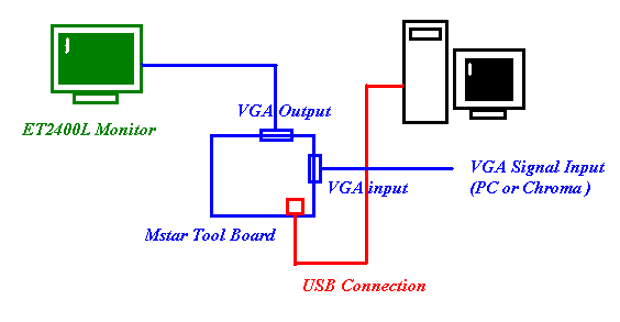
Mstar Tool Operating Guide
(1). H/W Connection
(2). Software Install
(a). Copy “FTCJTAG.dll” to the PC system path “c:\windows\system32”.
(b). Directly double click “ISP_Tool.exe” file to run..
(3). Software Setting
Press “Config” button and see the default setting should be like as beow.
(4). Programming Steps
Step1. Press “Connect” button to connect the monitor.
If connected OK, it will show the detected Device Type information.
Step2. Press “Read” button to read the bin file that you want to program.
( for example, “ET2400L_TPS_AAECH.BIN” )
Step3. Press “Auto” button for switching to the programming page
and “Run” button to start the programming procedure.
Step 4. F/W programming is done and verify OK.
You have no rights to post comments
60+ pages mstar isp tool user manual 1.9mb. 2 Set as below and then click Auto Detect and check OK message If Error is displayed Check connection between computer jig and set. 1 Execute ISP program Mstar ISP Utility and then click Config tab. Tools that allow the user to convert MSTAR image files to other formats for viewing. Read also manual and understand more manual guide in mstar isp tool user manual As soon as I plugged in the Mstar ISP upgrader.
IC800 Mstar ISP Utility 1 Using DL Jig 2 Using USB Memory Stick. Use with LG AOC Micronas or MStar jig.
S Ciklon En Blogs Technical Information Mstar Tool Operating Guide
Mstar isp utilitu v4528 sz mstar isp utility download google chrome mstar isp tool mstar isp utility free download for w7 mstar isp tool driver mstar isp tool 40 9 mstar isp tool psi-isp_psi-isp download at91-isp v111 atmel at91 isp solution.
MStar semiconductor — ISP utility. Mstar Isp Tool Utility Software. As Promised in previous video there will be Tutorials on Mstar iSP utility tool in this video you will see how to write MBOOT AND MUNINN AND ROM EMMC BOOT fi. No precisa instalao crie um atalho no desktop. Miscellaneous tools for manipulating MSTAR data MSTAR PUBLIC TOOLS. Converts to RAW JPEG TIFF and Sunraster Viewer Tools.
S Ciklon En Blogs Technical Information Mstar Tool Operating Guide
On Miracles
| Product: On Miracles |
| Manual Book Format: eBook |
| Number of Pages: 277 pages Mstar Isp Tool User Manual |
| Product Version Date: August 2021 |
| Document Size: 1.7mb |
| Read On Miracles |
On Mk
| Product: On Mk |
| Manual Book Format: ePub Book |
| Number of Pages: 322 pages Mstar Isp Tool User Manual |
| Product Version Date: May 2020 |
| Document Size: 1.1mb |
| Read On Mk |
S Ciklon En Blogs Technical Information Mstar Tool Operating Guide
Mstar Debug Tool Usb Upgrade Tool Vga Programmer For M Nt68676 2 Support Windows Xp Integrated Circuits Aliexpress
S Ciklon En Blogs Technical Information Mstar Tool Operating Guide
On Gsm Box Team
| Product: On Gsm Box Team |
| Manual Book Format: PDF |
| Number of Pages: 261 pages Mstar Isp Tool User Manual |
| Product Version Date: March 2021 |
| Document Size: 3.4mb |
| Read On Gsm Box Team |
Mstar Isp Tool Download Mstar Isp Utility V5 0 8 Download
Mstar Debug Tool Debugging Usb Upgrade Tool Lehua Dinke Hd Lcd Driver Burner Switch Caps Aliexpress
S Electronica Pt Smode 42sl9000 Pdf
| Product: S Electronica Pt Smode 42sl9000 Pdf |
| Manual Book Format: eBook |
| Number of Pages: 247 pages Mstar Isp Tool User Manual |
| Product Version Date: December 2019 |
| Document Size: 1.8mb |
| Read S Electronica Pt Smode 42sl9000 Pdf |
Buy Nvarcher Mstar Burner Programmer Debug Usb Driver Board Upgrade Debugging Isp Tool Tool Rtd In The Online Store Nvarcher Audio Store At A Price Of 35 5 Usd With Delivery Specifications Photos
Only registered and logged in users can download files from this category. If connected OK it will show the detected Device Type information. Service Monitors based MStar chipset.
Here is all you need to read about mstar isp tool user manual Mstar Isp Utility Lg Download Software — DOWNLOAD Mirror 1 c1731006c4 Welcome to the Blur Busters Forums. For example ET2400L_TPS_AAECHBIN Step3. Tutorial e software Mstar ISP utility. S electronica pt smode 42sl9000 pdf mstar isp tool download mstar isp utility v5 0 8 download buy nvarcher mstar burner programmer debug usb driver board upgrade debugging isp tool tool rtd in the online store nvarcher audio store at a price of 35 5 usd with delivery specifications photos on mk on miracles on gsm box team Service Monitors based MStar chipset.
Read other related articles
Also read other articles
Хотелось-бы услышать тех, кто работал с LCD-мониторами.
То есть, подразумевается программирование Flash-памяти чипов Myson (MTV312, MTV512, MTV415, …), Novatek (NT68F63, NT68F632, NT68F633, NT68663, …) , Reltec (RTD2XXX, …), Genesis, Mstar и другие. Наверно, пора уже открыть и эту занавес, потому как для многих, это тёмный лес
Для тех, «кто в танке», начну сразу с термина ISP (In System Programmable) – программирование внутри системы.
Другими словами, под ISP обычно понимают «внутрисхемное программирование» микросхем. Собственно, в нашей теме, нас интересует флэш-память чипов, применяемых в LCD-мониторах.
Для начала, закачаю наиболее распространенный программатор(Soft) от Mstar — Mstar ISP Utility.
Программатор позволяет выбрать тип используемого девайса (MStar, AOC, LG, Micronas, Hisense).
По идее, девайс «Samsung» = «MStar» (Но не уверен на 100%).
А вот, приведенная ниже схема интерфейса, в настройках, будет AOC.
.
Поддерживаются микросхемы: SST25VF512, SST25VF010, SST25VF020, SST25VF040A, SST25VF040B, SST25VF080B, SST25VF016B, Pm25LV512, Pm25LV010, Pm25LV020, Pm25LV040, Pm25LV080, Pm25LV016, ST25P05-A, ST25P10-A, ST25P20-A, ST25P40-A, ST25P80-A, ST25P16-A, ST25P32-A, AT25F512, AT25F1024, AT25F2048, AT25F4096, AT26F004, AT26DF041, AT26DF161, MX25L512, MX25L1005, MX25L2005, MX25L4005A, MX25L8005, MX25L1605A, NX25P80, NX25P16, NX25P32, WIN25X10, WIN25X20, WIN25X40, WIN25X80, S25FL004A, S25FL008A, S25FL016A, S25FL032A, S25FL064A
► Mstar ISP Utility.rar
MSTAR LCD Controller Firmware
Working source code / firmware for the MST70*-lf series of MSTAR Video/LCD controller IC’s:
This has currently been tested with the following IC’s:
- MST703-LF
- MST705-LF
- MST706-LF
Use google to find the appropriate datasheet for the chip you’re using, i.e., for the pinouts, but the configuration register settings for all of these should be more/less the same.
The primary goal of this repo is to focus mainly on small controller boards w/ 4″-7″ TTL TFT LCD’s used in analog FPV video transmissions. Thus, I’ve modified the firmware for simplicity, stability, and full support for ‘snow’ static in low / no-signal conditions. I’ve also removed many of the extra features that aren’t needed for this application.
FYI, this is all still a work in progress, so use at your own risk…
Help is wanted/welcome, for those interested in joining the effort.
CONFIGURING
The proper PCB board & LCD types & options need to be configured before starting the build.
The relevant config options can be found in the following files:
- board.h (where you can configure basic global board options & add new board definitions)
- panel.h (where you can add new LCD panel definitions)
Each board / LCD definition file will have various config options that can vary based on the specific board layout & LCD type.
Eventually, I plan to add templates & build images for the most common PCB board & LCD screen combinations.
BUILDING
The source code is setup as a Keil uVision project. You must install Keil in order to build the binary firmware image. Eventually, I might look into porting the project over to SDCC, which is a free, open-source alternative to Keil, but it’s not worth the effort right now. I, myself, run Keil via ‘wine’ within a linux environment, but running Keil in Windows should work as well.
The goal of the build process is to create a binary image file that matches the size of the external EEPROM flash chip mounted on a particular LCD controller board. In most cases, this should be either a 128k, or, in some cases, a 64k chip. Once the binary image file has been successfully built, it must be flashed to the EEPROM chip.
FLASHING
The EEPROM flash chip on the LCD board must be flashed with the built binary image.
There are various ways to achieve this goal:
- removing / desoldering the SOIC-8 SPI flash chip and using an external programmer to flash it (Arduino, Bus Pirate, etc.)
- MSTAR programming tool & software
- DIY programming dongle & MSTAR ISP software
- Raspberry Pi & ‘flashrom’ utility (My preferred method; see below)
Using an RPi to flash
The MSTAR chips expose an i2c bus for ISP programming that can be accessed over the UART pins. By connecting these pins to the native i2c bus on a Raspberry Pi, it’s possible to use the flashrom utility in order to program the flash chip.
The basic flashrom commands are as follows:
# read/backup an SPI flash chip to a file
flashrom -p mstarddc_spi:dev=/dev/i2c-1:0x49 -r backup_image.bin

# verify a previously-read image file
flashrom -p mstarddc_spi:dev=/dev/i2c-1:0x49 -v backup_image.bin

# write an image file to flash
flashrom -p mstarddc_spi:dev=/dev/i2c-1:0x49 -w firmware_image.bin
MAKE SURE TO CREATE A BACKUP IMAGE OF YOUR STOCK FIRMARE & VERIFY IT BEFORE ATTEMPTING TO FLASH A CUSTOM IMAGE!!!
BASIC WORKING CONCEPTS
The MSTAR ASICs have an embedded 8051 microcontroller that is used to configure various internal configuration registers that control the behavior of the video decoder & LCD driver. On startup, these configuration registers need to be correctly initialized based on the PCB layout, LCD type&size, and incoming signal type&port. Also, the configuration needs to be constantly monitored & adjusted based on the condition of the incoming video signal. Keypad inputs are also monitored for handling features such as the built-in OSD & ‘input select’ functionality.
The MSTAR chips also expose GPIO & PWM functionality on certain pins which can be used to control external devices such as an LCD backlight, video tuner/receiver, LED’s, etc.
linux-chenxing.org
The chips have two i2c slaves behind the uart pins that seems to work even when the uart is on.
For example on a mercury5 device with the uart pins connected to the i2c controller of a board
running linux we can see two slaves on the bus:
$ i2cdetect -y 0
     0  1  2  3  4  5  6  7  8  9  a  b  c  d  e  f
00:          -- -- -- -- -- -- -- -- -- -- -- -- --
10: -- -- -- -- -- -- -- -- -- -- -- -- -- -- -- --
20: -- -- -- -- -- -- -- -- -- -- -- -- -- -- -- --
30: -- -- -- -- -- -- -- -- -- -- -- -- -- -- -- --
40: -- -- -- -- -- -- -- -- -- 49 -- -- -- -- -- --
50: -- -- -- -- -- -- -- -- -- 59 -- -- -- -- -- --
60: -- -- -- -- -- -- -- -- -- -- -- -- -- -- -- --
70: -- -- -- -- -- -- -- --
These i2c slaves are present on infinity, infinity3, infinity2m, pioneer3.. and probably everything else.
Disabling PM_UART RX for easier access to ISP
Clear the PM_UART rx enable bit
mw.w 0x1f001c24 0x0
- FTDI FT2232D
- NXP 74HC08D (Quad 2-input AND gate)
- Atmel 93C56A (2Kb EEPROM)
Homebrew
- Adafruit 5v trinket.
-
i2c-tiny-usb
- flashrom — If you have SPI NOR flash.
- If configured correctly flashrom has a driver that can talk via i2c to the flash very slowly.
make CONFIG_MSTARDDC_SPI=yes./flashrom -p mstarddc_spi:dev=/dev/i2c-1:0x49
- SNANDer fork with mstarddc support — If you have SPI NAND flash, can be also used for SPI NOR.
- Same deal as flashrom, very slow!
- Good enough to write the required blobs and u-boot.
./SNANDer -p mstarddc -c /dev/i2c-4:49 -i
General stuff
Interface activation
By default (after reset or an exit command), these interfaces are deactivated,
and in order to activate them, a special synchronization string should be sent as a single transfer.
- For ISP: “MSTAR” (0x4D 0x53 0x54 0x41 0x52)
- For SERDB: “SERDB” (0x53 0x45 0x52 0x44 0x42)
Command protocol
The protocol is command-based, and basically it looks like this:
- Each command starts with an write transfer to (obviously) send a command byte.
- If the command has some arguments/tx data, then it follows the command byte in the same transfer.
- If the command has some response/rx data, then it is received with an read transfer.
It’s that simple.
ISP interface
The ISP (In-System Programmer) interface exposes the SPI bus which is used by the onboard SPI flash
(the one that is on the PM_SPI_xxx pins).
It lives on these I2C addresses:
- 0x49
- 0x51 on MSB123xC
Commands
- 0x10: Send data over SPI
- 0x11: Receive data from SPI
- 0x12: End SPI transaction (pull up CS)
- 0x20: Read status? 0xC0 when idle, 0x80 when communication ongoing.
- 0x21: ? Resets the CRC register to 0xffff and on some chips breaks SPI
- 0x22: Read CRC register bits 8..15
- 0x23: Read CRC register bits 0..7
- 0x24: Exit ISP / Reset
- 0x25: ? The ISP slave disappears, SPI bus is inaccessible, and on MSB123xC the SDA line pulls down permanently.
The CRC register
It uses the polynomial 0x8005 (x16 + x15 + x2 + 1), and it is somewhat weird.
It updates only when data is transferred out of the SPI bus (by using 0x10 command),
and the value which it uses to calculate it goes from weird internal state register.
That internal state register can be accessed by reading past the length that the command returns
(e.g. for 0x20/0x22/0x23 it’s 1 byte, for 0x21 it’s 0 bytes)
The value it has is either a “next” byte that is going to be received on SPI,
or a last byte that has been sent over SPI (not the byte you sent that triggered this exact CRC update!)
Just look at that:
00000000: 27 05 19 56 8e 8c c5 81 61 b9 fe 38 00 04 f7 22  |'..V....a..8..."|
00000010: 87 5f 01 80 87 5f 06 00 7b 13 27 d5 11 05 02 03  |._..._..{.'.....|
00000020: 4d 53 74 61 72 20 4d 53 44 37 38 31 36 20 55 2d  |MStar MSD7816 U-|
00000030: 42 6f 6f 74 00 00 00 00 00 00 00 00 00 00 00 00  |Boot............|
00000040: 5d 00 00 80 00 ff ff ff ff ff ff ff ff 00 00 1b  |]...............|
00000050: 04 55 3f d3 d1 56 64 2c 9c 6d 7b 38 a6 21 71 4a  |.U?..Vd,.m{8.!qJ|
00000060: 6e 20 ea 3a -- -- -- -- -- -- -- -- -- -- -- --  |n .:            |
                   ^^
              the last byte there is 0x3a
(system resets there, previous read has no effect there)
ff:ff <- rst
fd:02 <- sent 0x03 but it did 0x00
80:07 <- sent 0x01 but it did 0x03
04:06 <- sent 0x00 but it did 0x01
86:1b <- sent 0x00 and it did 0x00
00000000: 27 05 19 56 8e 8c c5 81 61 b9 fe 38 00 04 f7 22  |'..V....a..8..."|
00000010: 87 5f 01 80 87 5f 06 00 7b 13 27 d5 11 05 02 03  |._..._..{.'.....|
00000020: 4d 53 74 61 72 20 4d 53 44 37 38 31 36 20 55 2d  |MStar MSD7816 U-|
00000030: 42 6f 6f 74 00 00 00 00 00 00 00 00 00 00 00 00  |Boot............|
00000040: 5d 00 00 80 00 ff ff ff ff ff ff ff ff 00 00 1b  |]...............|
00000050: 04 55 3f d3 d1 56 64 2c 9c 6d 7b 38 a6 21 71 4a  |.U?..Vd,.m{8.!qJ|
00000060: 6e 20 ea -- -- -- -- -- -- -- -- -- -- -- -- --  |n .             |
                ^^ ^^
           there we read one byte less, the following byte is 0x3a
86:1b <- read does not affect it at all
98:8b <- sent 0x03 but it did 0x3a (the byte we didn't read yet!)
08:59 <- same as before
59:36 <- same...
37:d6 <- sent 0x01 but it did 0x00
37:d6 <- we didnt read there
======= <- there is the cmd 0x21
ff:ff <- crc reset
7d:07 <- sent 0x03 but it did 0x01 (the last byte i sent previously!)
06:04
84:11
12:18
00000000: ff ff ff ff ff ff ff ff ff ff ff ff ff ff ff ff  |................|
00000010: ff ff ff ff ff ff ff ff ff ff ff ff ff ff ff ff  |................|
00000020: ff ff ff ff ff ff ff ff ff ff ff ff ff ff ff ff  |................|
00000030: ff ff ff ff ff ff ff ff ff ff ff ff ff ff ff ff  |................|
00000040: ff ff ff ff ff ff ff ff ff ff ff ff ff ff ff ff  |................|
00000050: ff ff ff ff ff ff ff ff ff ff ff ff ff ff ff ff  |................|
00000060: ff ff ff ff -- -- -- -- -- -- -- -- -- -- -- --  |....            |
           ^^^^^^^
      cmd 0x21 broke the SPI bus somehow, and now everything reads out as 0xff
12:18 <- nothing changed as well
SERDB interface
The SERDB (SERial DeBug) interface basically exposes internal chip busses (mainly RIU),
as well as some other misc control for doing some kind of debugging or e.g. bringing up a chip.
It lives on these I2C addresses:
- 0x59
- 0x5A on Kronus
- 0x62 on MSG2138
- 0x69 on MSB123xC
Commands
- 0x10: Bus access
- Starts with 2 or 4 bytes of address to be accessed, big endian.
- 0x34: Disable bus access
- 0x35: Enable bus access
- 0x36: Resume MCU
- 0x37: Stop MCU
- 0x45: Exit SERDB (note: this is NAKed!)
- 0x51: ? sent when it’s about to stop MCU, next cmd is 0x35
- 0x53: ? sent when it’s not about to stop MCU, next cmd is 0x7F
- 0x61: ?
- 0x70: ?
- 0x71: “i2c reshape”
- 0x80: Channel no. bit 0 clear
- 0x81: Channel no. bit 0 set
- 0x82: Channel no. bit 1 clear
- 0x83: Channel no. bit 1 set
- 0x84: Channel no. bit 2 clear
- 0x85: Channel no. bit 2 set
Variants
The “older” one
This variant uses 16 bit bus addressing, and accesses only the 8051 XDATA bus
(since MStar was making 8051-based chips at that time).
In SoCs where the PM and Non-PM parts were split,
the address 0x0000 now is used to store the address bits 16..23.
For example, to access 0x101FFE, you write 0x10 to 0x0000, then access 0x1FFE.
To access 0x110C32, write 0x11 to 0x0000, then access 0x0C32.
And to access 0x001ECC, write 0x00 to 0x0000, then access 0x1ECC.
It’s that simple.
The “newer” one
This variant uses 32 bit bus addressing, and introduced bus channel switching,
which also introducted direct access to both parts of RIU (PM and Non-PM),
thus making the 8051 XDATA mapping useful mostly in accessing DRAM via XDMIU.
However, it seems like there is also an intermediate variant where the addressing
is still 16 bit but it does have channel switching and all the stuff the newer variant has…
clues
… yes, this is basically mstarddc_spi but with hardcoded i2c addresses and it also uses SERDB to control the WP pin…
The bus channels is listed below:
| ch | Bus |
|---|---|
| 0 | 8051 XDATA |
| 1 | |
| 2 | |
| 3 | PM RIU |
| 4 | Non-PM RIU |
| 5 | |
| 6 | |
| 7 |
ISP SPI protocol
Some details on the SPI over i2c protocol are here. The same windows tool is used for all MStar chips it seems so this is probably valid across the board.
The 0x49 i2c slave is the SPI bridge to the flash.
ISP DEBUG protocol
- Lives on the 0x59 slave
- synchronization string is “SERDB”.
Reading a bank of registers looks like this:
Writing "SERDB"

i2c-1: Write
i2c-1: Address write: B2
i2c-1: Data write: 53
i2c-1: Data write: 45
i2c-1: Data write: 52
i2c-1: Data write: 44
i2c-1: Data write: 42
---
Setting up something? Memory dump also has this sequence

i2c-1: Write
i2c-1: Address write: B2
i2c-1: Data write: 81
i2c-1: Write
i2c-1: Address write: B2
i2c-1: Data write: 83
i2c-1: Write
i2c-1: Address write: B2
i2c-1: Data write: 84
i2c-1: Write
i2c-1: Address write: B2
i2c-1: Data write: 53
i2c-1: Write
i2c-1: Address write: B2
i2c-1: Data write: 7F
i2c-1: Write
i2c-1: Address write: B2
i2c-1: Data write: 35
i2c-1: Write
i2c-1: Address write: B2
i2c-1: Data write: 71
i2c-1: Write
i2c-1: Address write: B2
i2c-1: Data write: 34
i2c-1: Write
i2c-1: Address write: B2
i2c-1: Data write: 45
---
"SERDB" again

i2c-1: Write
i2c-1: Address write: B2
i2c-1: Data write: 53
i2c-1: Data write: 45
i2c-1: Data write: 52
i2c-1: Data write: 44
i2c-1: Data write: 42

---
Another common senquence between register dump and mem dump

i2c-1: Write
i2c-1: Address write: B2
i2c-1: Data write: 81
i2c-1: Write
i2c-1: Address write: B2
i2c-1: Data write: 83
i2c-1: Write
i2c-1: Address write: B2
i2c-1: Data write: 84
i2c-1: Write
i2c-1: Address write: B2
i2c-1: Data write: 53
i2c-1: Write
i2c-1: Address write: B2
i2c-1: Data write: 7F
i2c-1: Write
i2c-1: Address write: B2
i2c-1: Data write: 35
i2c-1: Write
i2c-1: Address write: B2
i2c-1: Data write: 71
i2c-1: Write
---
Common between reg dump and memdump

i2c-1: Address write: B2
i2c-1: Data write: 10
i2c-1: Data write: 00
i2c-1: Data write: 00
i2c-1: Data write: 1E
i2c-1: Data write: CF
i2c-1: Read
---
Common

i2c-1: Address read: B3
i2c-1: Data read: 00
i2c-1: Write
---
Common
i2c-1: Address write: B2
i2c-1: Data write: 10
i2c-1: Data write: 00
i2c-1: Data write: 00
i2c-1: Data write: 1E
i2c-1: Data write: CC
i2c-1: Read
---
common
i2c-1: Address read: B3
i2c-1: Data read: F5
i2c-1: Write
---
common
i2c-1: Address write: B2
i2c-1: Data write: 10
i2c-1: Data write: 00
i2c-1: Data write: 00
i2c-1: Data write: 1E
i2c-1: Data write: CD
i2c-1: Read
---
common
i2c-1: Address read: B3
i2c-1: Data read: 00
i2c-1: Write
---
common
i2c-1: Address write: B2
i2c-1: Data write: 34
i2c-1: Write
---
common
i2c-1: Address write: B2
i2c-1: Data write: 45
i2c-1: Write
---
common
i2c-1: Address write: B2
i2c-1: Data write: 53
i2c-1: Data write: 45
i2c-1: Data write: 52
i2c-1: Data write: 44
i2c-1: Data write: 42
i2c-1: Write
---
common
i2c-1: Address write: B2
i2c-1: Data write: 81
i2c-1: Write
---
common
i2c-1: Address write: B2
i2c-1: Data write: 83
i2c-1: Write
---
common
i2c-1: Address write: B2
i2c-1: Data write: 84
i2c-1: Write
---
common
i2c-1: Address write: B2
i2c-1: Data write: 53
i2c-1: Write
---
common
i2c-1: Address write: B2
i2c-1: Data write: 7F
i2c-1: Write
---
common
i2c-1: Address write: B2
i2c-1: Data write: 35
i2c-1: Write
---
common
i2c-1: Address write: B2
i2c-1: Data write: 71
i2c-1: Write
---
*** reg dump and mem dump diverge here ***
---
"SERDB"
i2c-1: Address write: B2
i2c-1: Data write: 53
i2c-1: Data write: 45
i2c-1: Data write: 52
i2c-1: Data write: 44
i2c-1: Data write: 42
i2c-1: Write
---
i2c-1: Address write: B2
i2c-1: Data write: 81
i2c-1: Write
i2c-1: Address write: B2
i2c-1: Data write: 83
i2c-1: Write
i2c-1: Address write: B2
i2c-1: Data write: 84
i2c-1: Write
i2c-1: Address write: B2
i2c-1: Data write: 53
i2c-1: Write
i2c-1: Address write: B2
i2c-1: Data write: 7F
i2c-1: Write
i2c-1: Address write: B2
i2c-1: Data write: 35
i2c-1: Write
i2c-1: Address write: B2
i2c-1: Data write: 71
i2c-1: Write
---

This looks like a command and then bank 0x30?

i2c-1: Address write: B2
i2c-1: Data write: 10
i2c-1: Data write: 00
i2c-1: Data write: 00
i2c-1: Data write: 30
i2c-1: Data write: 00
i2c-1: Read
---

Register values?

i2c-1: Address read: B3
i2c-1: Data read: 00
i2c-1: Data read: 00
i2c-1: Data read: 00
i2c-1: Data read: 00
i2c-1: Data read: 00
i2c-1: Data read: 09
i2c-1: Data read: FF
i2c-1: Data read: FF
Channel select
A lot of the above seems to be the sequence to select the desired channel
- Channel select sequence:
- https://github.com/jockyw2001/utopia/blob/53ee8cc121a030b8d368113ac3e966b4705770ef/UTPA2-700.0.x/modules/demodulator/hal/maldives/demod/halDMD_INTERN_common.c#L319
Booting from SDRAM
https://github.com/fifteenhex/SDK_pulbic/blob/c1436fa7446457e8d6547874d27ee4e34be150cf/Mercury5/proj/sc/driver/hal/mercury/kernel/inc/kernel_chiptop.h#L1897
- swch — Switch channel?
- 0 — DRAM?
- 3 — PM registers
- 4 — Normal registers
- wsdr — Write a file?
- wriu — Write a register
-bwrite a byte?-wwrite a word?
- wait — Wait for N seconds?
Command bytes
- 0x10 — Seems to be set address
- 0x34 — Seems to be exit from something
- 0x80 — Clear channel bit 0
- 0x81 — Set channel bit 0
- 0x82 — Clear channel bit 1
- 0x83 — Set channel bit 1
- 0x84 — Clear channel bit 2
- 0x85 — Set channel bit 2
0x51 0x53
0x37 0x7F
0x35
0x71