
- Машины
- Nissan
- X-Trail
- II (t31)
- Nissan X-Trail
18 мая 2016
toor76
Был 1 неделю назад
Михаил, 48 лет
Я езжу на Nissan X-Trail (до этого — Toyota Raum)
Иркутск, Россия
Подписаться
Сообщение
Nissan X-Trail T-31 вариант от автонав
Nissan X-Trail T-31 официальный мануал
Nissan X-Trail T-30
Мануал на Nissan Connect
18 мая 2016
Метки: другое
10
Ранее Доработка чехла на брелок сигнализации
Далее Любитетелям дрифта — небольшая подборочка
Разместить рекламу
Реклама
Машины в продаже
Комментарии
10
Войдите или зарегистрируйтесь, чтобы писать комментарии, задавать вопросы и участвовать в обсуждении.
Войти
Зарегистрироваться
AutoBOTT
Я езжу на Nissan X-Trail I (t30)
Можете закинут на Яндекс диск мануал на Xtrail T30, не как не разберусь с Dropbox…
2 года
Romanov-86
Я езжу на Nissan X-Trail II (t31)
спасибо. скачал.
8 лет
kyrok84
Я езжу на Jeep Grand Cherokee (WK2)
и Nissan X-Trail II (t31)
Есть книга Эксплуатация, обслуживание и ремонт Хитрого с 2007 г. и рестал 2011 г., кому надо пишите, залью куда-нить типа Яндекс диска…
9 лет
ComeAgain
Я езжу на Honda Fit (3G)
отличные ссылки. скачал — спасибо!
9 лет
toor76
Автор
Я езжу на Nissan X-Trail II (t31)
Пожалуста)
9 лет
Energy73RUS
Я езжу на Volkswagen Tiguan (2G)
(до этого — Nissan X-Trail II (t31))
Спасибо, в закладки!
9 лет
SKORPIONCIK
Я езжу на Nissan X-Trail II (t31)
а че подругому нельзя скачать?
9 лет
toor76
Автор
Я езжу на Nissan X-Trail II (t31)
Черкни куда залить и что именно)
9 лет
sibers42
Я езжу на Honda Stream (RN6-9)
и Nissan X-Trail II (t31)
Спасибо)
9 лет
toor76
Автор
Я езжу на Nissan X-Trail II (t31)
Всегда рад помочь)
9 лет

BRAKE CONTROL SYST EM
F BRAKES
A
B
SECTION BRC
BRAKE CONTROL SYSTEM
CONTENTS
ABS
PRECAUTIONS …………………………………………………. 4
Precautions for Supplemental Rest raint System
(SRS) “AIR BAG” and “SEAT BELT PRE-TEN-
SIONER” ………………………………………………………… 4
Precautions for Brake System ……………………………. 4
Precautions for Brake Control ……………………………. 4
PREPARATION ………………………………………………….. 5
Commercial Service Tools …………………………………. 5
SYSTEM DESCRIPTION …………………………………….. 6
System Diagram ………………………………………………. 6
Functions …………………… ……………….. …………………. 6
ABS ……………………….. …………………………………… 6
EBD ……………………….. …………………………………… 6
Operation That Is Not “System Error” …………………. 6
ABS ……………………….. …………………………………… 6
Hydraulic Circuit Diagram …………………………………. 7
CAN Communication ………………………………………… 7
SYSTEM DESCRIPTION ……………………………….. 7
TROUBLE DIAGNOSIS ………………………………………. 8
Fail-Safe Function ……………………………………………. 8
ABS, EBD …………………………………………………….. 8
How to Perform Trouble Diagnosis for Quick and
Accurate Repair ………………………………………………. 8
INTRODUCTION ……………………….. …………. ……… 8
DIAGNOSIS FLOW CHART …………………………… 9
ASKING COMPLAINTS ……………………………….. 10
EXAMPLE OF DIAGNOSIS SHEET ………………. 10
Component Parts Location ………………………………..11
Schematic …………………………………………………….. 12
Wiring Diagram — ABS — ………………………………. 13
Control Unit Input/Output Signal Standard …………. 17
REFERENCE VALUE FROM CONSULT-II ……… 17
CONSULT-II Functions (ABS) ………………………….. 18
CONSULT-II MAIN FUNCTION ……………………… 18
CONSULT-II BASIC OPERATION PROCEDURE
… 18
SELF-DIAGNOSIS …………. …………………………… 18
DATA MONITOR …………………………………………. 20
ACTIVE TEST …………………………………………….. 21
For Fast and Accurate Diagnosis ………………………23
PRECAUTIONS FOR DIAGNOSIS ………………… 23
Basic Inspection ……………………………………………..23
BRAKE FLUID LEV EL, LEAKAGE AN D BRAKE
PAD …………………………………………………………… 23
POWER SUPPLY CIRCUIT TERMINAL LOOSE-
NESS AND BATTERY ………………………………….. 24
INSPECTION OF ABS WARNING LAMP ………..24
TROUBLE DIAGNOSIS FOR SYSTEM … …… ……. ….25
Wheel Sensor ………………………………………………… 25
INSPECTION PROCEDURE ………………………… 25
ABS Actuator and Electric Unit (Control Unit) ……..27
INSPECTION PROCEDURE ………………………… 27
ABS Actuator and Electric Unit (Control Unit) Power
Supply and Ground ………………………………………….27
INSPECTION PROCEDURE ………………………… 27
ABS Actuator Relay or ABS Motor Relay ……………28
INSPECTION PROCEDURE ………………………… 28
G Sensor (Only AWD Models) …………………………..29
INSPECTION PROCEDURE ………………………… 29
CAN Communication ……………………………………….31
INSPECTION PROCEDURE ………………………… 31
Component Inspection ……………………………………..32
PARKING BRAKE SWITCH …………………………..32
BRAKE FLUID LEVEL SWITCH ……………………. 32
TROUBLE DIAGNOSIS FOR SYMPTOMS ………….. 33
Excessive ABS Function Operation Frequency …… 33
Unexpected Pedal Reaction …………………………….. 33
The Stopping Distance Is Long …………………………. 34
ABS Function Does Not Operate ……………………….35
Pedal Vibration or ABS Operation Sound Occurs …35
ABS Warning Lamp Indication Is Not Normal ………35
WHEEL SENSORS …………………………………………… 36
Removal and Installation …………………………………. 36
COMPONENTS ………………… ………………………… 36
REMOVAL ………………………………………………….. 36
INSTALLATION …………………………………………… 36
SENSOR ROTOR …………………………………………….. 37
Removal and Installation (2WD Models) …………….37
REMOVAL ………………………………………………….. 37
C
D
E
BRC
G
H
I
J
K
L
M
Revision: 2006 July 2006 X-Trail
BRC-1

INSTALLATION …………………………………………….37
Removal and Installation (AWD Models) …………….37
REMOVAL …………………………………………………..37
INSTALLATION …………………………………………….37
ACTUATOR AND ELECTRIC UNIT (ASSEMBLY) …38
Removal and Installation ………………………………….38
COMPONENTS ……………… ……………………………38
REMOVAL …………………………………………………..39
INSTALLATION …………………………………………….39
G SENSOR ………………………………………………………. 40
Removal and Installation (Only AWD Models) ……..40
REMOVAL …………………………………………………..40
INSTALLATION …………………………………………….40
VDC/TCS/ABS
PRECAUTIONS …………………… …… ……. …… ……. …….41
Precautions for Supplemental Restraint System
(SRS) “AIR BAG” and “SEAT BELT PRE-TEN-
SIONER” ………………. …………………….. ……………….. 41
Precautions for Brake System …………………………..41
Precautions for Brake Control ………………………….. 41
PREPARATION …………………………………………………42
Commercial Service Tools ……………… …… …………..42
ON-VEHICLE SERVICE …………………………………….. 43
Adjustment of Steering Angle Sensor Neutral Posi-
tion …………………. ……………………………………………. 43
SYSTEM DESCRIPTION …………………………………… 44
System Diagram ……………………………………………..44
Functions ………………………………………………………. 44
ABS ……………………………………………………………44
EBD ……………………………………………………………44
ABLS (ACTIVE BRAKE LSD) …………………………44
TCS …………………………………………………………… 44
VDC …………………………………………………………… 45
Operation That Is Not “System Error” …………………45
ABS ……………………………………………………………45
TCS …………………………………………………………… 45
VDC …………………………………………………………… 45
Hydraulic Circuit Diagram …………………………………46
CAN Communication ……………………………………….46
SYSTEM DESCRIPTION ………………………………46
TROUBLE DIAGNOSIS ……………………………………..47
Fail-Safe Function …………………………………………..47
ABS, EBD, ABLS ………………………………………….47
VDC/TCS ………………………. ……………………………47
How to Perform Trouble Diagnosis For Quick and
Accurate Repair ………………………………………………47
INTRODUCTION …………………. ………………………47
DIAGNOSIS FLOW CHART …………………………..48
ASKING COMPLAINTS …………………………………49
EXAMPLE OF DIAGNOSIS SHEET ………………..49
Component Parts Location ……………………………….50
Schematic …………….. ……………………………………….51
Wiring Diagram — VDC — ……………………………….52
Control Unit Input/Output Signal Standard …………..58
REFERENCE VALUE FROM CONSULT-II ………58
CONSULT-II Functions (ABS) ……………………………60
CONSULT-II MAIN FUNCTION ……. …… ……. …….60
CONSULT-II BASIC OPERATION PROCEDURE
…61
SELF-DIAGNOSIS ………. ……………………………….61
DATA MONITOR ………………………………………….64
ACTIVE TEST ………………………………………………66
For Fast and Accurate Diagnosis ……………………….68
PRECAUTIONS FOR DIAGNOSIS …………………68
Basic Inspection ………………………………………………69
BRAKE FLUID LEVEL, L EAKAGE AND BRAKE
PAD ……………….. ………………………………………. ….69
POWER SUPPLY CIRCUIT TERMINAL LOOSE-
NESS AND BATTERY …………………………………..69
ABS WARNING LAMP, BRAKE WARNING
LAMP , VDC OFF INDICA T OR LAMP, A ND SLIP
INDICATOR LAMP ………………………………………..69
TROUBLE DIAGNOSIS FOR SYSTEM ………………..71
Wheel Sensor …………………………………. …… ……. ….71
INSPECTION PROCEDURE ……………………… ….71
Engine System ………………………………………………..73
INSPECTION PROCEDURE ……………………… ….73
VDC/TCS/ABS Control Unit ………………………………73
INSPECTION PROCEDURE ……………………… ….73
Pressure Sensor ……………………………………………..73
INSPECTION PROCEDURE ……………………… ….73
Steering Angle Sensor ……………………………………..74
INSPECTION PROCEDURE ……………………… ….74
Yaw Rate/Side G Sensor ………………………………….76
INSPECTION PROCEDURE ……………………… ….76
Solenoid and VDC Switching Valve ……………………77
INSPECTION PROCEDURE ……………………… ….77
Actuator Motor and Motor Relay ………………………..79
INSPECTION PROCEDURE ……………………… ….79
Actuator Relay ………………………………………………..80
INSPECTION PROCEDURE ……………………… ….80
Stop Lamp Switch Circuit ………………………………….81
INSPECTION PROCEDURE ……………………… ….81
VDC/TCS/ABS Control Unit Power And Ground ….82
INSPECTION PROCEDURE ……………………… ….82
Park/Neutral Position (PNP) Switch (Only A /T Mod-
els) ………………………………………………………………..83
INSPECTION PROCEDURE ……………………… ….83
Brake Fluid Level Switch …………………………………..84
INSPECTION PROCEDURE ……………………… ….84
CAN Communication ……………………………………….85
INSPECTION PROCEDURE ……………………… ….85
Component Inspection ……………………………………..85
VDC OFF SWITCH ……………………………………….85
PA RKING BRAKE SWITCH ……………………………86
BRAKE FLUID LEVEL SWITCH ……………………..86
MOTOR RELAY AND ACTUATOR RELAY ………86
VDC ACTUATOR ………………………………………….87
TROUBLE DIAGNOSIS FOR SYMPTOMS …………..88
Excessive ABS Function Operation Frequency ……88
Unexpected Pedal Reaction ……………………………..88
The Stopping Distance Is Long ………………………….89
ABS Function Does Not Operate ……………………….90
Pedal Vibration or ABS Operation Sound Occurs …90
Vehicle Jerks During VDC/TCS/ABS Control ……….90
ABS Warning Lamp Indication Is Not Normal ………91
Revision: 2006 July 2006 X-Trail
BRC-2

Slip Indicator Lamp Indication Is Not Normal ……… 91
VDC OFF Indicator Lamp Indication Is Not Normal … 92
Brake Warning Lamp Indication Is Not Normal …… 92
WHEEL SENSORS …………………………………………… 93
Removal and Installation …………………………………. 93
COMPONENTS ………………………………………….. 93
REMOVAL ………………………………………………….. 93
INSTALLATION …………………………………………… 93
SENSOR ROTOR …………………………………………….. 94
Removal and Installation …………………………………. 94
REMOVAL ………………………………………………….. 94
INSTALLATION …………………………………………… 94
VDC/TCS/ABS CONTROL UNIT ………………………… 95
Removal and Installation …………………………………. 95
REMOVAL ………………………………………………….. 95
INSTALLATION …………………………………………… 95
ACTUATOR …………………………… ………………………… 96
Removal and Installation …………………………………. 96
COMPONENTS ………………… ………………………… 96
REMOVAL ………………………………………………….. 97
INSTALLATION …………………………………………… 97
G SENSOR ………………………………………………………. 98
Removal and Installation …………………………………. 98
REMOVAL ………………………………………………….. 98
INSTALLATION …………………………………………… 98
STEERING ANGLE SENSOR ……………………………. 99
Removal and Installation …………………………………. 99
REMOVAL ………………………………………………….. 99
INSTALLATION …………………………………………… 99
VDC OFF SWITCH …………………………………………..100
Removal and Installation ………………………………..100
REMOVAL …………………………………………………100
INSTALLATION ………………………………………….100
A
B
C
D
E
BRC
G
H
K
M
I
J
L
Revision: 2006 July 2006 X-Trail
BRC-3
PRECAUTIONS
[ABS]
[ABS]
PRECAUTIONS PFP:00001
Precautions for Supplemental Restraint System (SRS) “AIR BAG” and “SEAT
BELT PRE-TENSIONER”
The Supplemental Restraint System such as “AIR BAG” and “SEAT BELT PRE-TENSIONER”, used along
with a front sea t belt , helps t o redu ce th e r isk or s everi ty of injury to th e driv er an d front passenge r for c ertain
types of collision. Info rmation necessary to service the system safely is included in the SRS and SB section of
this Service Manual.
WARNING:
● To avoid rendering the SRS inoperativ e, which cou ld increase the risk of persona l injury or death
in the event of a collision which would result in air bag inflation, all maintenance must be performed by an authorized NISSAN/INFINITI dealer.
● Improper maintenance, in cluding incorrect removal a nd installation of the SRS, can lead to per-
sonal injury caused by unintentional activation of the system. For rem ova l of Sp iral Ca ble an d Air
Bag Module, see the SRS section.
● Do not use electrical test equipme nt on any circuit related to the SRS unle ss instructed to in this
Service Manual. SRS wiring harnesses can be identified by yellow and/or orange harnesses or
harness connectors .
AFS002PO
Precautions for Brake System AFS002LO
● Recommended fluid is brake fluid “DOT 3”. Refer to MA-10, «RECOMMENDED FLUIDS AND LUBRI-
CANTS»
● Do not reuse drained brake fluid.
● Be careful not to splash brake fluid on painted areas such as body. If brake fluid is splashed, wipe it off
and flush area with water immediately.
● Do not use mineral oils such as ga soline or kerosene. They will ruin rubber parts of the hydraulic system.
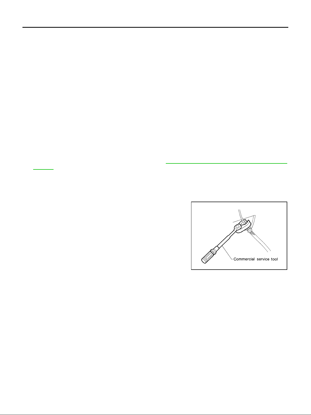
● Use flare nut torque wrench when removing and installing brake
tube.
● Brake system is an important saf ety part. If a b rake fluid leak is
detected, always dis assembl e the affected part. If a malf unction
is detected, replace part with a new one.
● Before working, turn ignition switch OFF and disconnect con-
nectors of ABS a ctua tor and electric u ni t (con trol unit) or batter y
cables.
● When installing brake piping, be sure to check torque.
WARNING:
Clean brake pads and shoes with a waste cloth, then wipe with
a dust collector.
SBR686C
Precautions for Brake Control AFS002LP
● Just after starting vehicle after ignition switch ON, brake pedal may vibrate or motor operating noise may
be heard from engine room. This is a normal status of opera tion check.
● When an error is indicated by ABS or another warning lamp, collect all necessary information from cus-
tomer (what symptoms are present under what conditions) and check for simple causes before starting
diagnostic servicing. Besides electrical system inspection, check brake booster operation, brake fluid
level, and fluid leak s.
● If tire size and type are us ed in an imprope r combinat ion, or brake pads are not Genuine NISSAN parts,
stopping distance or steering stability may deteriorate.
● If there is a radio, antenna, or antenna lead-in wire (including wiring) near control module, ABS function
may have a malfunction or error.
● If aftermarket parts (car st ereo, CD pl ayer, etc.) have bee n installe d, ch eck f or inc iden ts such as h arness
pinches, open circuits, and improper wiring.
Revision: 2006 July 2006 X-Trail
BRC-4
PREPARATION
[ABS]
PREPARATION PFP:00002
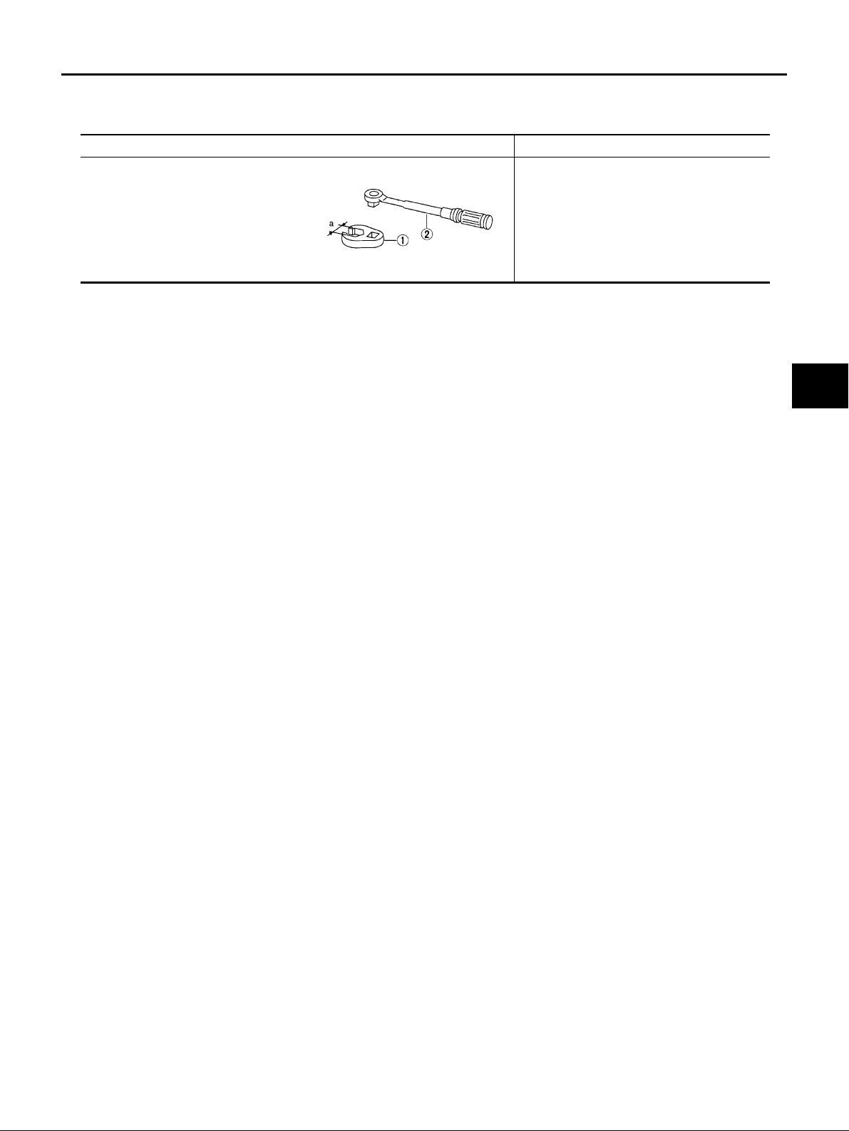
Commercial Service Tools AFS002PB
Tool name Description
1.Flare nut crowfoot
a: 10 mm (0.39 in)
2.Torque wrench
Removing and installing each brake piping
A
B
C
S-NT360
D
E
BRC
G
H
I
J
K
Revision: 2006 July 2006 X-Trail
BRC-5
L
M
SYSTEM DESCRIPTION
[ABS]
SYSTEM DESCRIPTION PFP:00000
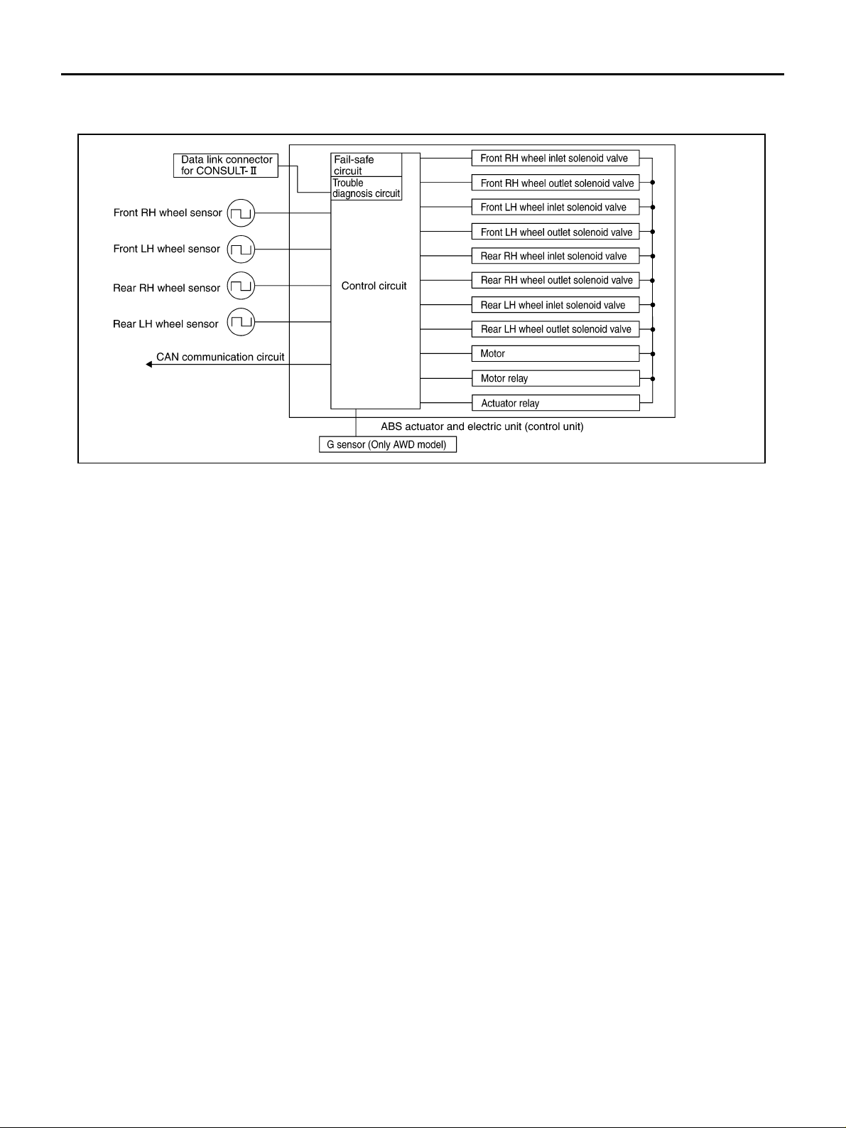
System Diagram AFS002LR
SFIA2390E
Functions AFS002P6
ABS
● The Anti-Lock Brake System is a function that detects wheel revolution while braking, and it improves
handling stability during sudden braking by el ectrically preventing 4 whe el lock. Maneuverabilit y is also
improved for avoiding obstacles.
● Electrical System Diagnosis by CONSULT-II is av ailable.
EBD
● Electronic B rak e Dist ribut ion is a fu ncti on that det ect s subt le sl ipp ag es bet ween f ront and rea r whee ls du r-
ing braking, and it improves handling stability by electronically controlling Brake Fluid Pressure which
results in reduced rear wheel slippage.
● Electrical System Diagnosis by CONSULT-II is av ailable.
Operation That Is Not “Sy stem Error” AFS002P7
ABS
● When starting engine or just after starting veh icle, brake pe dal may vibrate or the motor operatin g noise
may be heard from engine room. This is a normal states of the operation check.
● During ABS operation, brake pedal lightly vibrates and a mechanical noise may be heard. This is normal.
● Stopping distance may be longer th an that o f vehi cles with out ABS when vehi cle d rives on rou gh, gra vel,
or snow-covered (fresh, deep snow) roads.
Revision: 2006 July 2006 X-Trail
BRC-6
SYSTEM DESCRIPTION
[ABS]
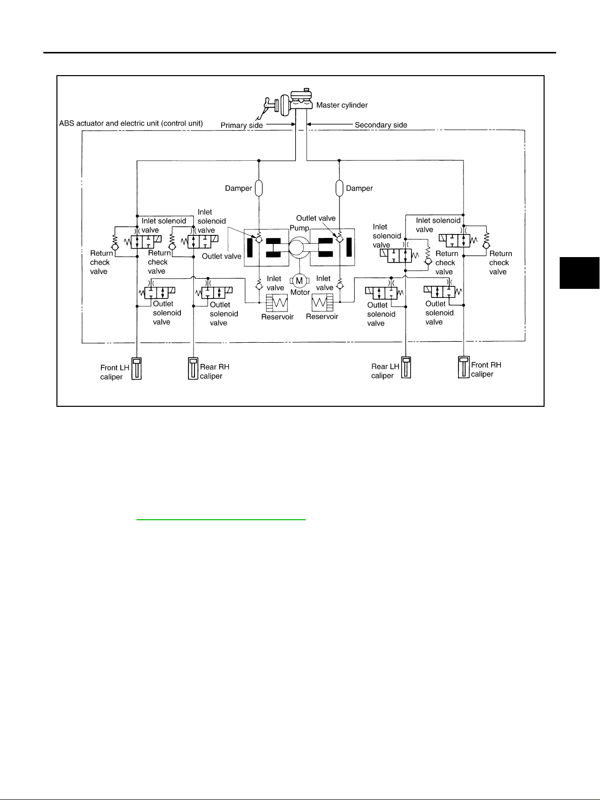
Hydraulic Circuit Diagram AFS002LV
A
B
C
D
E
BRC
G
SFIA2479E
CAN Communication AFS0035N
SYSTEM DESCRIPTION
CAN (Controller Area Network) is a serial communication line for real time application. It is an on-vehicle multiplex communication line with high data communication speed and excellent error detection ability. Many electronic control units are equipped onto a vehicle, and each control unit shares information and links with other
control units during opera tion (not independent). In CA N communication, cont rol units are connected with 2
communicatio n lines ( CAN H lin e, CAN L li ne) all owi ng a high ra te of in forma tion tr ans missi on wit h less wir ing.
Each control unit transmits/receives data but selectively reads required data only.
For details, refer to LAN-21, «
CAN Communication Unit» .
H
I
J
K
L
M
Revision: 2006 July 2006 X-Trail
BRC-7
TROUBLE DIAGNOSIS
[ABS]
TROUBLE DIAGNOSIS PFP:00004
Fail-Safe Function AFS0038H
ABS, EBD
In case of electrical malfunction with ABS, ABS warning lamp will turn on. In case of electrical incident with
EBD, ABS warning lamp will turn on. Simultaneously, ABS become one of following conditions of Fail-Safe
function.
1. For ABS malfunction, o nl y EB D is activ at ed an d c on di tio n o f ve hi cl e i s sam e c o nd iti on of veh ic le s wi tho ut
ABS function.
NOTE:
In step 1 shown abov e, self -diag nosi s wh en ig nitio n sw itch is t urned ON and when v ehic le starts at in itial
time is performed. ABS self-d iagnosis noise may be heard as usual.
2. For EBD malfunction, EBD and ABS become inoperative, and condition of vehicle is same as condition of
vehicles without ABS, EBD function.
How to Perform Trouble Diagnosis for Quick and Accurate Repair AFS002LX
INTRODUCTION
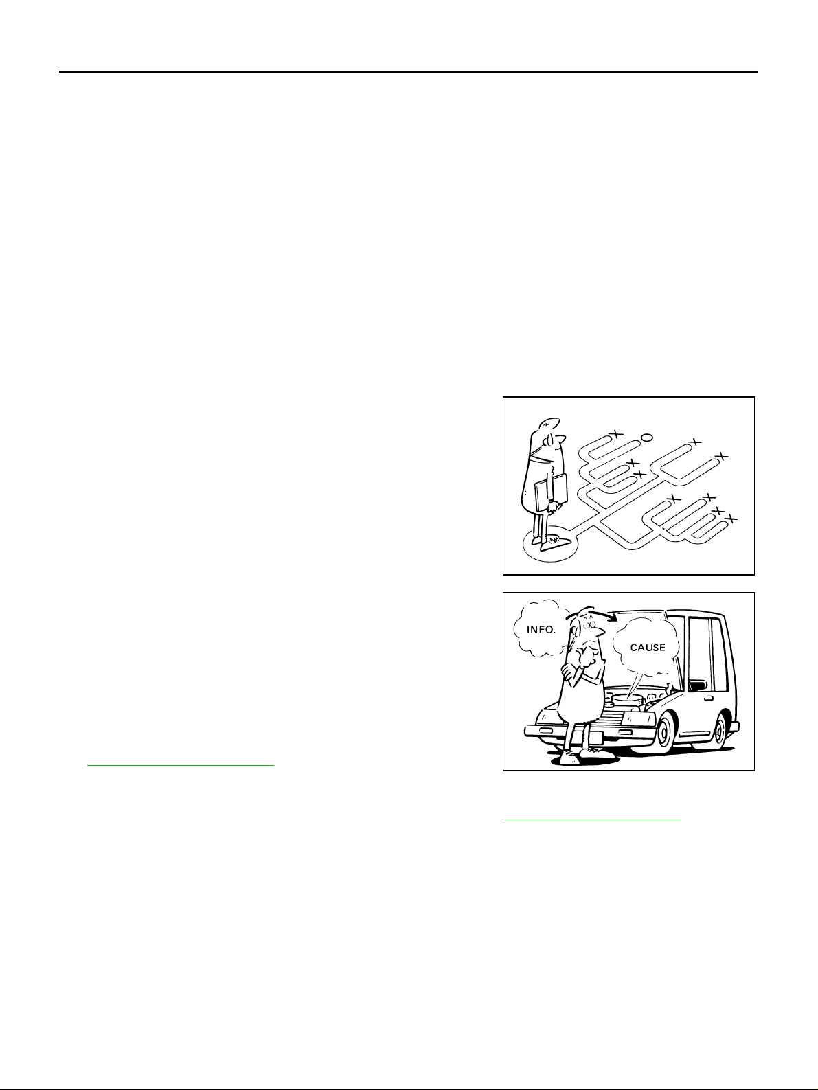
● To perform trouble diagnosis, it is the mos t important to have un derstandin g about veh icle syst ems (con —
trol and mechanism) thoroughly.
● It is also important to cla rify c ustom er compla ints befo re insp ec-
tion.
First of all, reproduce symptom, and understand it fully.
Ask customer about his/her complaint s carefully. I n some cases,
it will be necessary to check symptom by driving vehicle with
customer.
NOTE:
Customers are no t professionals. Do not assum e “maybe customer means…” or “maybe cus tomer mentioned this symptom”.
● It is essential to check symptoms right from beginning in order to
repair a malfunction completely.
For an intermittent malfunction, it is important to reproduce
symptom based o n interv iew wi th cust omer and past exam ples.
Do not perform inspection on ad hoc basis. Most intermittent
malfunctions are c a us ed b y poor contacts. In this c a se, it will be
effective to shake suspected harness or connector by hand.
When repairs are performed without any symptom check, no
one can judge if malfunction has actually been eliminated.
● After diagnosis, make sure to perfo rm “e rase me mory”. Refer t o
BRC-19, «
● For an intermitten t malfunction, move harness or harness c on-
ERASE MEMORY» .
nector by hand to check poor contact or false open circuit.
● Always read “ GI section” to confirm general precautions. Refer to GI-4, «General Precautions» .
EFJ0028D
SEF233G
Revision: 2006 July 2006 X-Trail
BRC-8
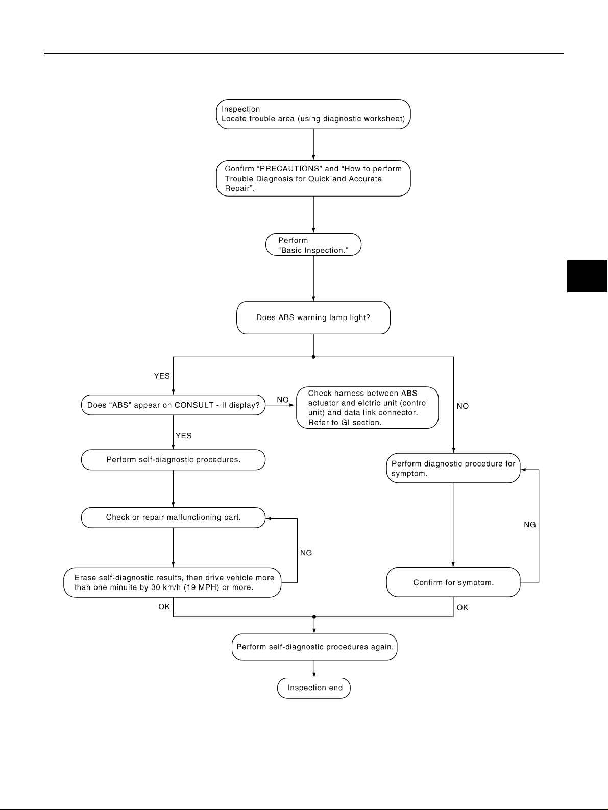
DIAGNOSIS FLOW CHART
TROUBLE DIAGNOSIS
[ABS]
A
B
C
D
E
BRC
G
H
K
M
I
J
L
PFIA0701E
Revision: 2006 July 2006 X-Trail
BRC-9
TROUBLE DIAGNOSIS
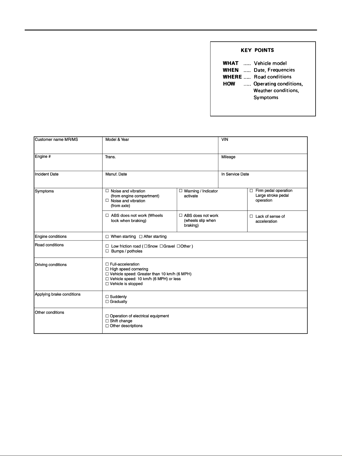
ASKING COMPLAINTS
● Complaints vary depending on the person. It is important to clar-
ify the customer’s actual remarks.
● Ask the customer about what symp toms are presen t and under
what conditions. Use the information to reproduce the symptom
while driving.
● It is also imp ortant to us e diagnosis sheet so as not to miss vital
information.
EXAMPLE OF DIAGNOSIS SHEET
[ABS]
SBR339B
LFIA0176E
Revision: 2006 July 2006 X-Trail
BRC-10
TROUBLE DIAGNOSIS
[ABS]
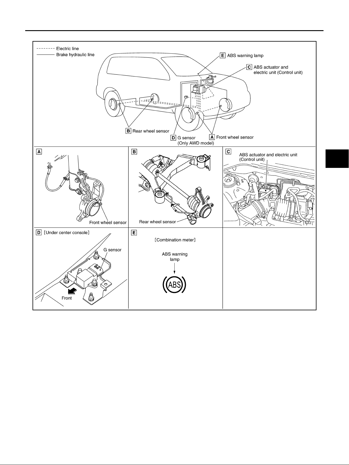
Component Parts Location AFS002LY
A
B
C
D
E
BRC
G
SFIA2391E
H
I
J
K
L
M
Revision: 2006 July 2006 X-Trail
BRC-11
TROUBLE DIAGNOSIS
[ABS]
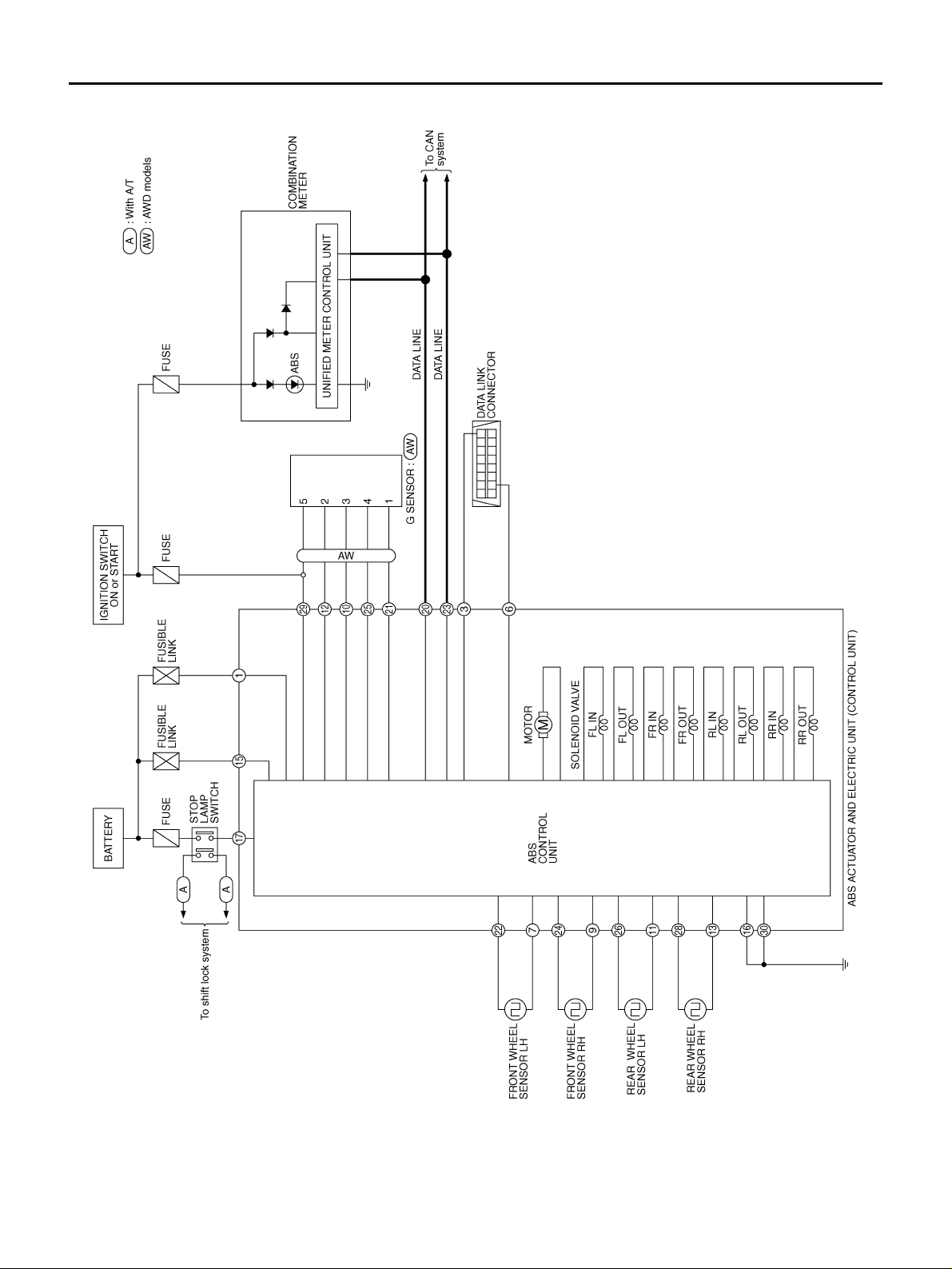
Schematic AFS002LZ
TFWB0019E
Revision: 2006 July 2006 X-Trail
BRC-12
TROUBLE DIAGNOSIS
[ABS]
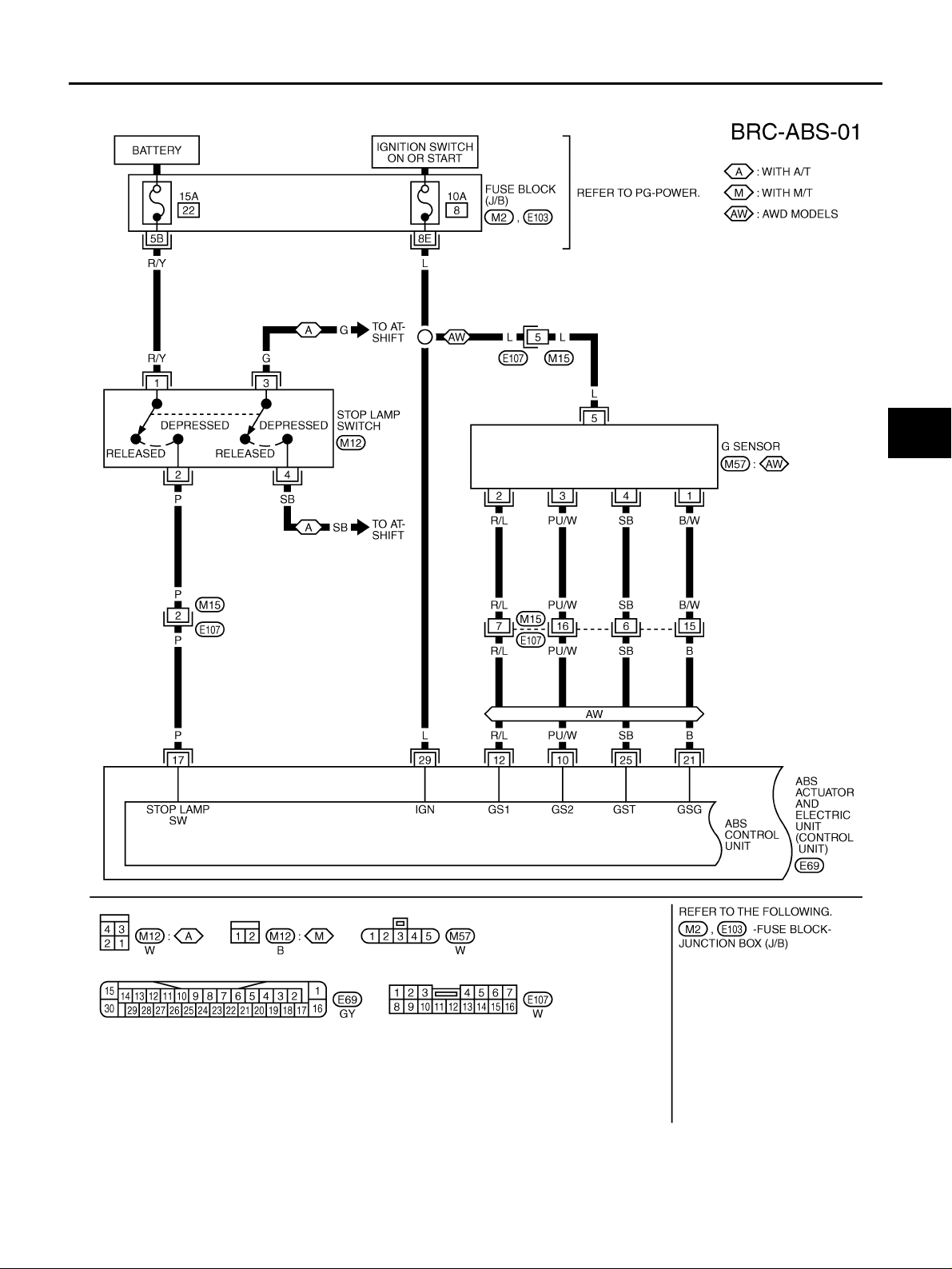
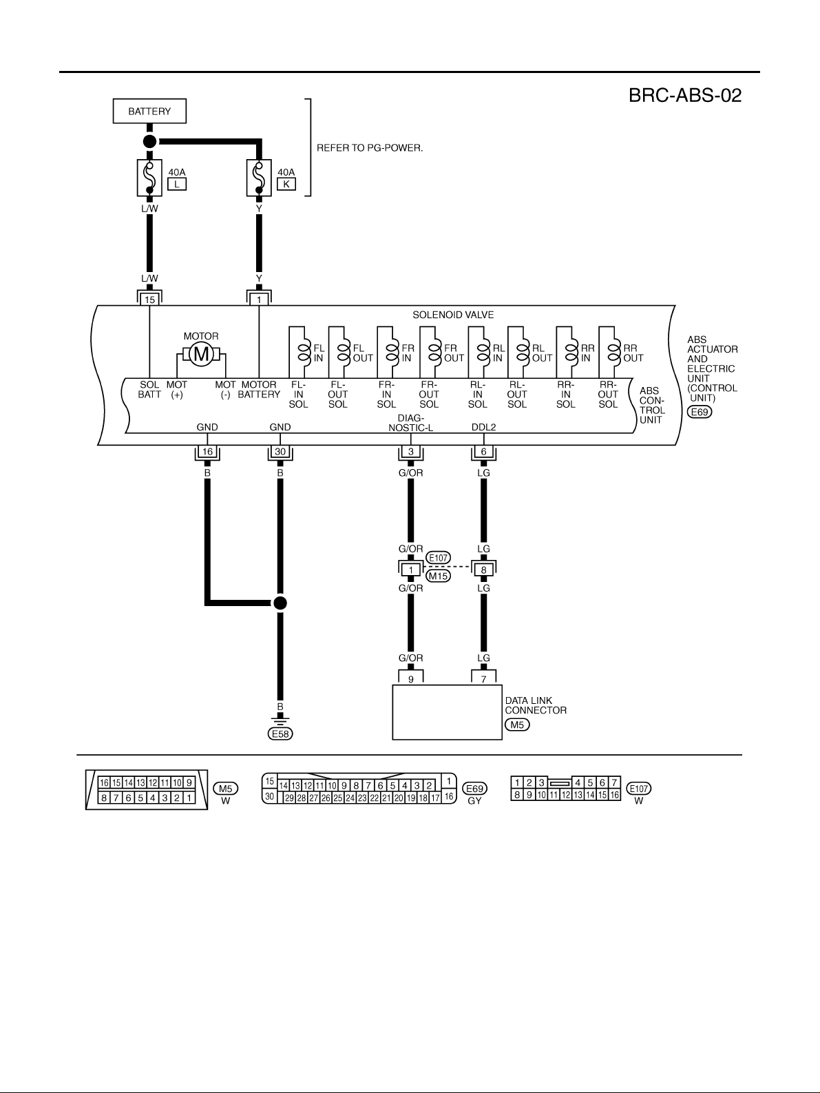
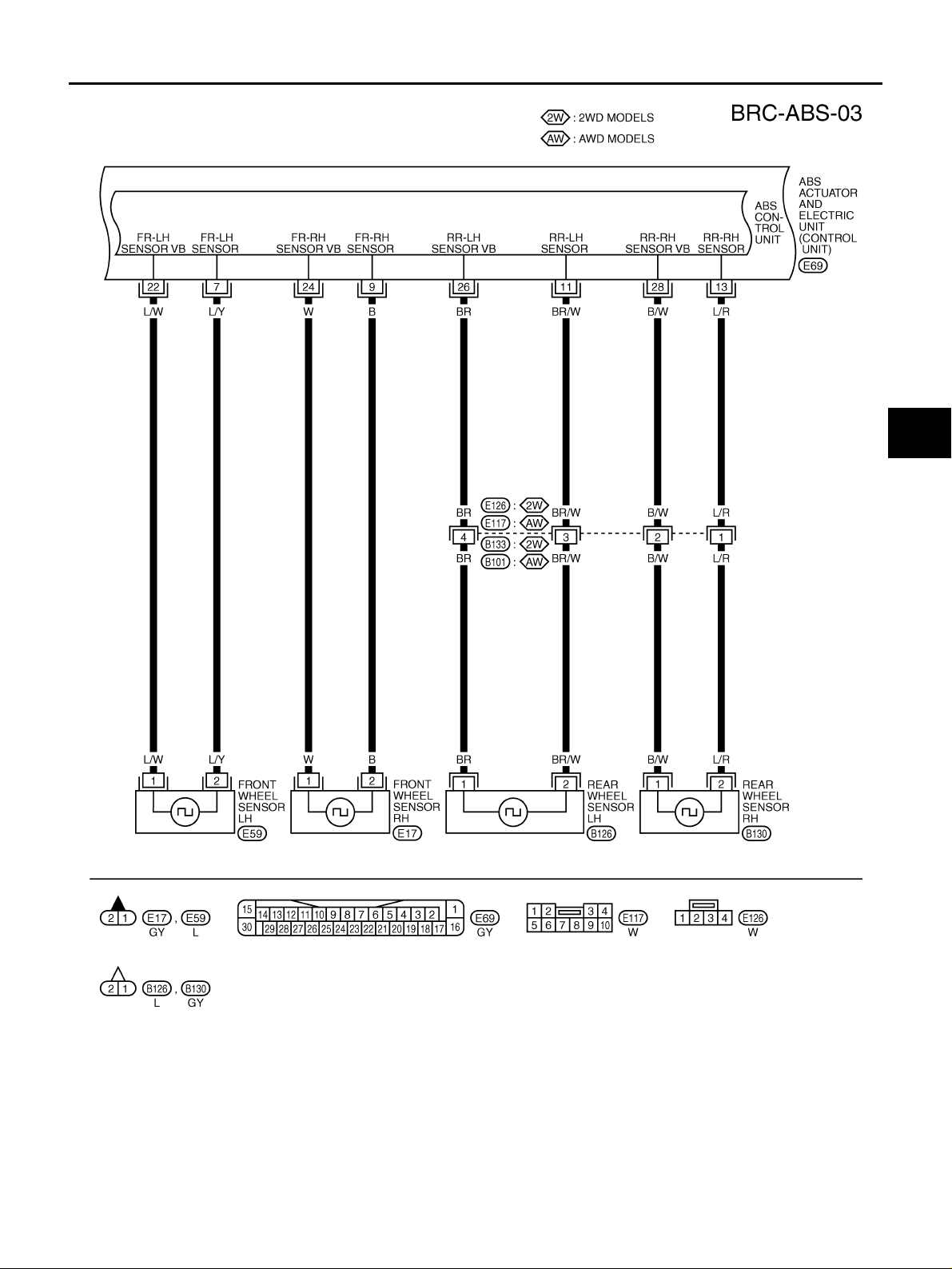
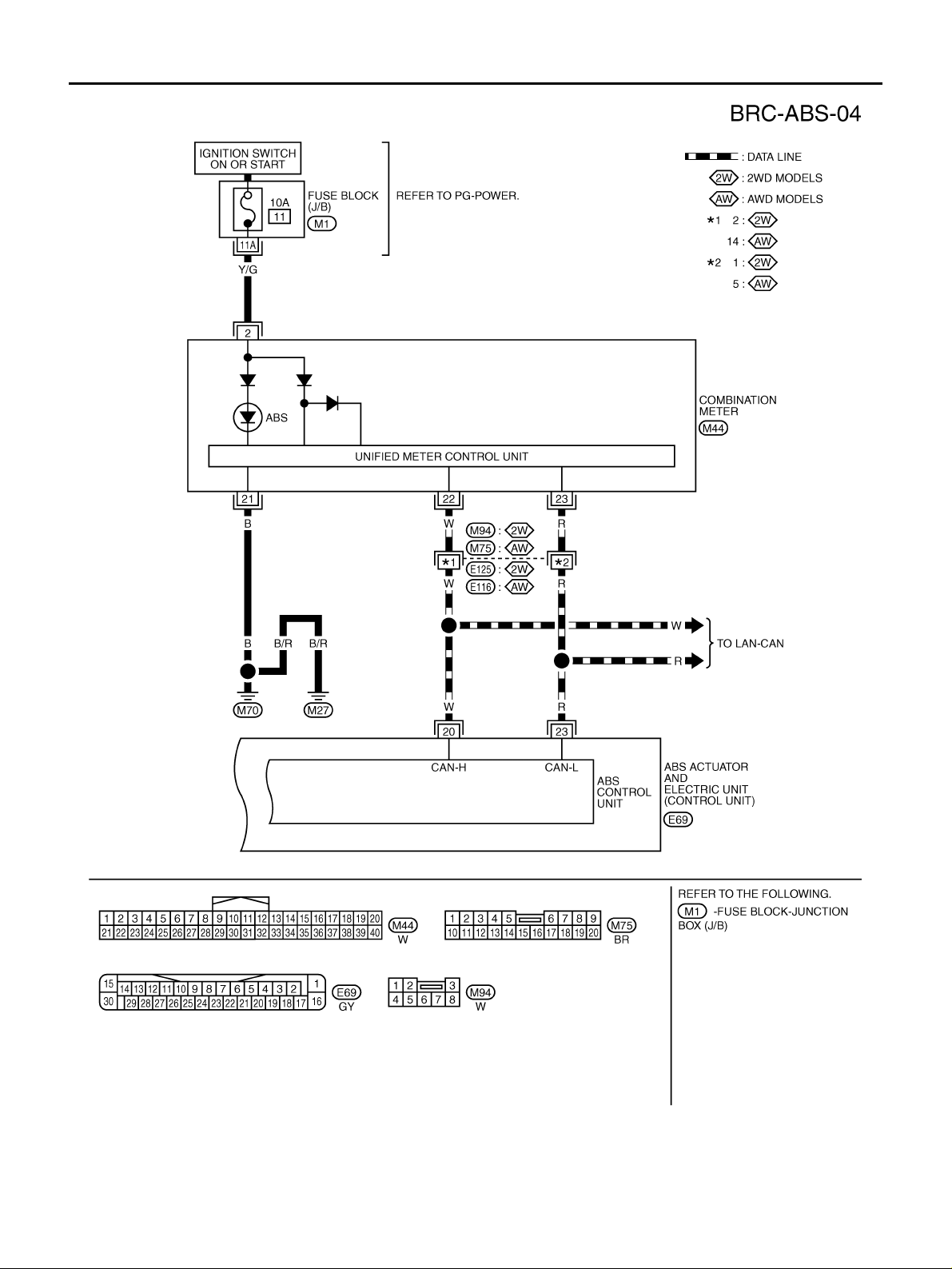
Wiring Diagram — ABS — AFS002M0
A
B
C
D
E
BRC
G
H
K
M
I
J
L
TFWB0020E
Revision: 2006 July 2006 X-Trail
BRC-13
TROUBLE DIAGNOSIS
[ABS]
TFWB0003E
Revision: 2006 July 2006 X-Trail
BRC-14
TROUBLE DIAGNOSIS
[ABS]
A
B
C
D
E
BRC
G
H
K
M
I
J
L
TFWB0021E
Revision: 2006 July 2006 X-Trail
BRC-15
TROUBLE DIAGNOSIS
[ABS]
TFWB0022E
Revision: 2006 July 2006 X-Trail
BRC-16
TROUBLE DIAGNOSIS
[ABS]
Control Unit Input/Output Signal Standard AFS002M1
REFERENCE VALUE FROM CONSULT-II
CAUTION:
The display shows the co ntrol unit ca lcula tion data, so a normal valu e might be displa yed ev en in the
event the output circuit (harness) is open or short — circulated.
Data monitor
Data monitor item Display item
FR LH SENSOR
FR RH SENSOR
RR LH SENSOR
RR RH SENSOR
DECEL G-SEN 1
DECEL G-SEN 2
ABS IN SOL
ABS OUT SOL
STOP LAMP SW
MOTOR RELAY
ACTUATOR RELAY
ABS WARN LAMP
BATTER Y VOLT
EBD SIGNAL
ABS SIGNAL
EBD FAIL SIG
ABS FAIL SIG
Note 1: Confirm tire pressure is the standard value.
Note 2: ABS warning lamp ON/OFF timing.
ON: When the ignition switch is turned ON or when an err or is detect ed.
OFF: After the ignition switch is turned ON (when syst em is norm al).
Wheel speed calculated using signals
from all four wheel
sensors
Fore-and-aft gravity
detected by G sensor
Operation status of all
solenoid valve
Brake pedal operation
status
Motor and motor relay
operation status
Actuator relay operation status
ABS warning lamp on
condition (Note 2)
Battery voltage supplied to ABS actuator
and electric unit (control unit)
EBD operation
ABS operation
System fail signal status
Vehicle stopped 0 [km/h]
Vehicle running (Note 1)
When vehicle is stopped on
level ground
When G sensor is tilted toward
the front with G sensor mounting nuts removed
When the actuator solenoid
operates or during a fail-safe
When the actuator relay operates and the actuator solenoid
does not operate
Brake pedal depressed ON
Brake pedal not depressed OFF
When the motor relay and
motor are operating
When the motor relay and
motor are not operating
When the actuator relay is
operating
When the actuator relay is not
operating
When ABS warning lamp is
ON
When ABS warning lamp is
OFF
Ignition switch ON 10 — 16 V
EBD active
ABS active
EBD not active
ABS not active
EBD Fail
ABS Fail
EBD normal
ABS normal
Condition
Reference values
in normal opera-
tion
Nearly matches
the speedometer
display (± 10 % or
less)
OFF
ON
ON
OFF
ON
OFF
OFF
ON
ON
OFF
ON
OFF
ON
OFF
Reference: Inspection
item
BRC-25, «
BRC-29, »
(Only AWD Models)»
BRC-28, »
Relay or ABS Motor
Relay»
Stop lamp switch circuit
BRC-28, »
Relay or ABS Motor
Relay»
BRC-24, »
OF ABS WARNING
LAMP»
BRC-27, »
and Electric Unit (Control Unit) Power Supply
and Ground»
EBD system
ABS system
Wheel Sensor»
G Sensor
ABS Actuator
ABS Actuator
INSPECTION
ABS Actuator
A
B
C
D
E
BRC
G
H
I
J
K
L
M
Revision: 2006 July 2006 X-Trail
BRC-17
TROUBLE DIAGNOSIS
[ABS]
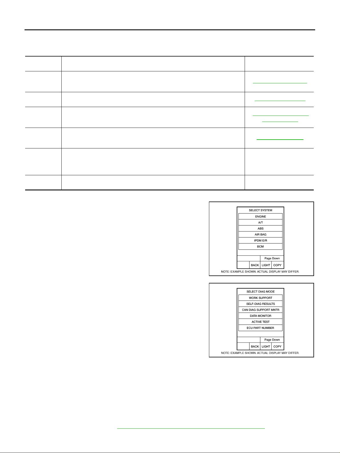
CONSULT-II Functions (ABS) AFS002M2
CONSULT-II MAIN FUNCTION
CONSULT-II can display each diagnostic item using the diagnostic test modes shown following.
Diagnostic
test mode
SELF-DIAGNOSTIC
RESULTS
DATA MONITOR
CAN DIAG
SUPPORT
MNTR
ACTIVE TEST
FUNCTION
TEST
ECU PART
NUMBER
Self-diagnostic results can be read and erased quickly. BRC-18, «
Input/Output data in the ABS actuator and electric unit (control unit) can be read. BRC-20, «
The result of transmit/receive diagnostic of CAN com m uni cation can be read.
Diagnostic Test Mode in which CONSULT-II drives some actuators apart from the
ABS actuator and electric unit (control unit) and also shifts some parameters in a
specified range.
This mode is used to inform customers when their vehi cl e condition requires periodic maintenance.
ABS actuator and electric unit (control unit) part number can be read. —
Function Reference
Self-Diagnosis»
Data Monitor»
LAN-13, «
“CONSULT-II OPERATION
MANUAL (FUNCTION
CAN Diagnostic
Support Monitor»
BRC-21, «Active Test»
Separate volume
TEST)”
CONSULT-II BASIC OPERATION PROCEDURE
1. Touch “ABS” in the “SELECT SYSTEM” screen.
2. Select the required diagnostic location from the “SELECT DIAG
MODE” screen.
BCIA0030E
BCIA0031E
SELF-DIAGNOSIS
OPERATION PROCEDURE
1. Turn ignition switch OFF.
2. Connect CONSULT-II and CONSULT-II CONVERTER to data link connector.
3. Turn ignition sw itch ON.
4. Start engine and drive vehicle at 30 km/h (19 MPH) or more for appro xi ma tely 1 minute.
5. After stopping vehicle, with the engine running, touc h “START (NISSAN BASED VHCL)”, “ABS”, “SELFDIAG RESULTS” in order on the CONSULT-II screen.
If “ABS” is not indicated, go to GI-37, «
Revision: 2006 July 2006 X-Trail
CONSULT-II Data Link Connector (DLC) Circuit» .
BRC-18

TROUBLE DIAGNOSIS
[ABS]
6. The self-dia gn os ti c resu lt s ar e d is pla yed . ( Touch “PRINT” to pr in t out se lf -d ia gn os tic r e sul t s, i f nece ss ar y. )
● Check ABS warn ing lamp if “NO FAILURE” is displayed.
7. Perform the appropriate inspection from the display item list, and repair or replace the malfunction ing
component. Refer to BRC-19, «
8. Start engine and drive vehicle at 30 km/h (19 MPH) or more for approximately 1 minute.
CAUTION:
When the wheel sensor malfunc tions, a fter inspec ting the w heel se nsor sys tem, the ABS warni ng
lamp will not turn off even when the s ystem is normal unless the vehicle is driving at approx imately 30 km/h (19 MPH) or more for approximately 1 minute.
DISPLAY ITEM LIST» .
A
B
C
ERASE MEMORY
1. Turn ignition switch OFF.
2. Start engine and touch “START (NISSAN BASED VHCL)”, “ABS”, “SELF-DIAG RESULTS”, “ERASE
MEMORY” in order on the CONSULT-II screen to erase the error memory.
CAUTION:
If the error memory is not erased, re-perform the operation from step 4.
3. Perform sel f-diagnosis again, and make sure that diagnostic memory is erased.
4. Drive vehicle at 30 km/h (19 MPH) or more for approximately 1 minute as the final inspection, and make
sure that the ABS warning lamp is turned off.
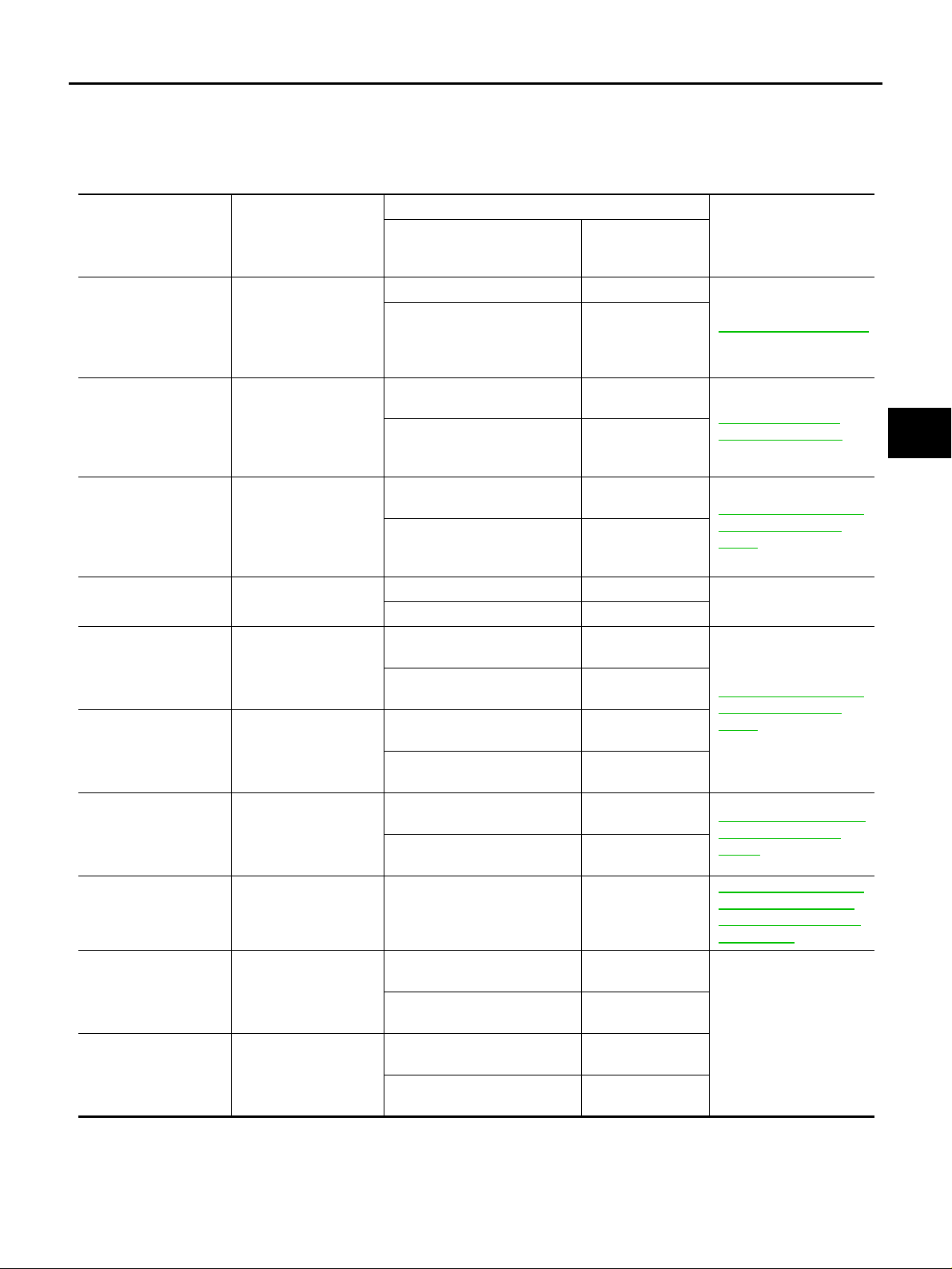
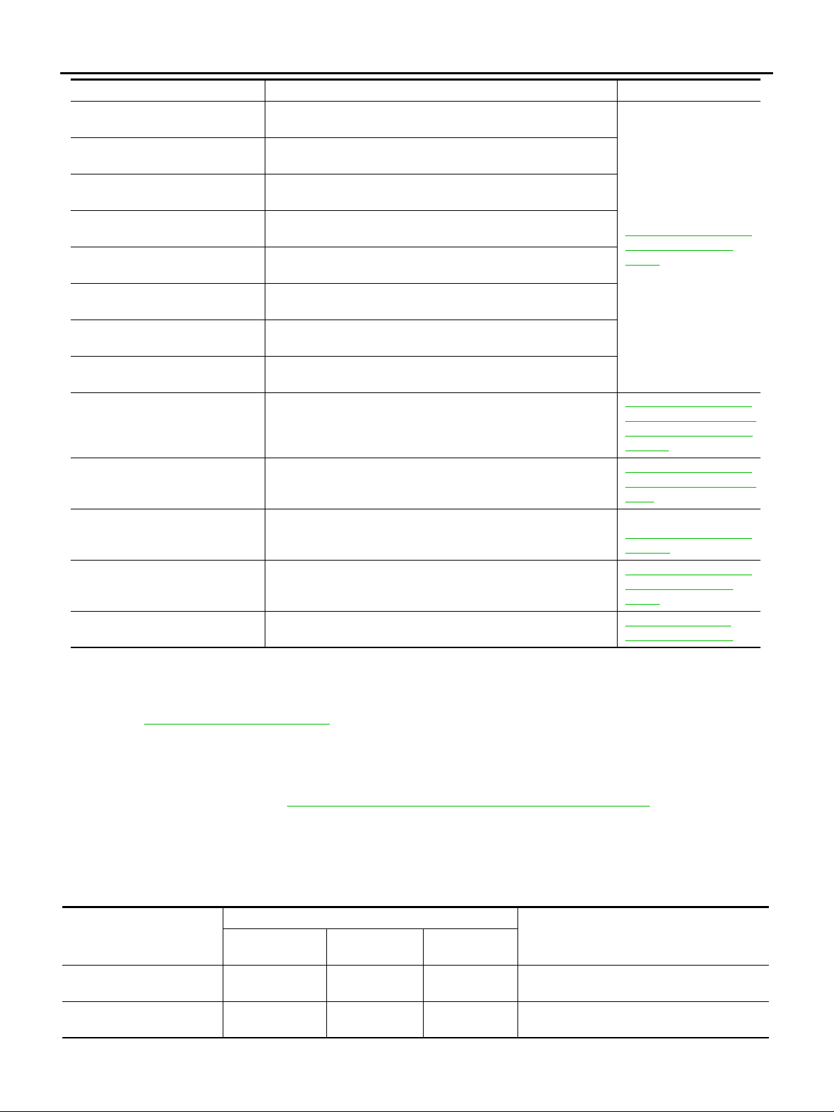
DISPLAY ITEM LIST
Diagnostic item Malfunction is detected when… Check circuit
FR LH SENSOR – 1 Circuit of front LH wheel sensor is open.
RR RH SENSOR – 1 Circuit of rear RH wheel sensor is open.
FR RH SENSOR – 1 Circuit of front RH wheel sensor is open.
RR LH SENSOR – 1 Circuit of rear LH wheel sensor is open.
When the circuit in the front LH wheel sensor is short -circ ui te d.
Or when the sensor power voltage is outside the standard. When
FR LH SENSOR – 2
RR RH SENSOR – 2
FR RH SENSOR – 2
RR LH SENSOR – 2
MAIN RELAY When the control unit detects an error in the actuator relay circuit.
the distance between the wheel sensor and sensor rotor is too
large and the sensor pulse cannot be recogniz ed by t he control
unit.
When the circuit in the rear RH wheel sensor is short- circ ui te d.
Or when the sensor power voltage is outside the standard. When
the distance between the wheel sensor and sensor rotor is too
large and the sensor pulse cannot be recogniz ed by t he control
unit.
When the circuit in the front RH wheel sensor is shor t-ci rcu ited.
Or when the sensor power voltage is outside the standard. When
the distance between the wheel sensor and sensor rotor is too
large and the sensor pulse cannot be recogniz ed by t he control
unit.
When the circuit in the rear LH wheel sensor is short-circuited. Or
when the sensor power voltage is outside the standard. When
the distance between the wheel sensor and sensor rotor is too
large and the sensor pulse cannot be recogniz ed by t he control
unit.
BRC-25, «
(Note 1)
BRC-28, »
Relay or ABS Motor
Relay»
Wheel Sen sor»
ABS Actuator
D
E
BRC
G
H
I
J
K
L
M
Revision: 2006 July 2006 X-Trail
BRC-19
TROUBLE DIAGNOSIS
[ABS]
Diagnostic item Malfunction is detected when… Check circuit
FR LH IN ABS SOL
FR LH OUT ABS SOL
RR RH IN ABS SOL
RR RH OUT ABS SOL
FR RH IN ABS SOL
FR RH OUT ABS SOL
RR LH IN ABS SOL
RR LH OUT ABS SOL
LOW POWER VOLTAGE
ABS CONTROLLER
CAN COMM CIRCUIT When there is an error in the CAN communication circuit.
PUMP MOTOR
G SENSOR (Only AWD model)
Note 1: After completing repairs of shorted sensor circuit, when ignition switch is turned ON, ABS warning lamp turns on. Make sure that
ABS warning lamp turns off w hile driving vehi cle at 30 km/h (19 MPH) or m ore for approximat ely 1 minute according to se lf-diagnosis
procedure. In addition, if wheel sensor 2 is displ ay ed fo r wheel s, check wheel sensor circuit and also check control unit power voltage.
Note 2: When e rrors ar e detected in seve ral syst ems, in cluding CAN com municat ion c ircuit [ U1000 ], troubl eshoot CA N co mmun ication
circuit. Refer to LAN-16, «
CAN COMMUNICATION» .
When the control unit detects an error in the front left inlet solenoid circuit.
When the control unit detects an error in the front left outlet solenoid circuit.
When the control unit detects an error in the rear right inlet solenoid circuit.
When the control unit detects an error in the rear right outlet solenoid circuit.
When the control unit detects an error in the front right inlet solenoid circuit.
When the control unit detects an error in the front right outlet
solenoid circuit.
When the control unit detects an error in the rear left inlet solenoid circuit.
When the control unit detects an error in the rear left outlet solenoid circuit.
When the ABS actuator and electric unit (control unit)
power voltage is lower than normal.
When there is an internal error in the ABS actuator and electric
unit (control unit).
During actuator motor operation with ON, when actuator motor
turns OFF or when control line for actuator motor relay is open.
G sensor is malfunctioning, or signal line of G sensor is ope n or
shorted.
BRC-28, »
Relay or ABS Motor
Relay»
BRC-27, »
and Electric Unit (Control
Unit) Power Supply and
Ground»
BRC-27, »
and Electric Unit (Control
Unit)»
BRC-31, «CAN Communication» (Note 2)
BRC-28, »
Relay or ABS Motor
Relay»
BRC-29, »
(Only AWD Models)»
ABS Actuator
ABS Actuator
ABS Actuator
ABS Actuator
G Sensor
DATA MONITOR
OPERATION PROCEDURE
1. Touch “START (NISSAN BASED VHCL)”, “ABS”, “DATA MONITOR” in order on the CONSULT-II screen.
If “ABS” is not indicated, go to GI-37, «
CONSULT-II Data Link Connector (DLC) Circuit» .
2. At the monitor item selecti on screen, touch one of th e items “ECU INPUT SIGNALS”, “MA IN SIGNALS”
or. “SELECTION FROM MENU”.
3. Touch “START” to proceed to the data monitor screen.
DISPLAY ITEM LIST
×: Standard –: Not applicable
SELECT MONITOR ITEM
Data monitor item (Unit )
FR LH SENSOR
[km/h]
FR RH SENSOR
[km/h]
Revision: 2006 July 2006 X-Trail
ECU INPUT SIG-
NALS
×××
×××
MAIN SIGNALS
SELECTION
FROM MENU
BRC-20
Wheel speed calculated by front LH whee l
sensor signal is displayed.
Wheel speed calculated by front RH wheel
sensor signal is displayed.
Remarks

TROUBLE DIAGNOSIS
[ABS]
Data monitor item (Unit)
RR LH SENSOR
[km/h]
RR RH SENSOR
[km/h]
DECEL G-SEN 1
(ON/OFF)
(Only AWD model)
DECEL G-SEN 2
(ON/OFF)
(Only AWD model)
FR LH IN SOL
(ON/OFF)
FR LH OUT SOL
(ON/OFF)
RR RH IN SOL
(ON/OFF)
RR RH OUT SOL
(ON/OFF)
FR RH IN SOL
(ON/OFF)
FR RH OUT SOL
(ON/OFF)
RR LH IN SOL
(ON/OFF)
RR LH OUT SOL
(ON/OFF)
STOP LAMP SW
(ON/OFF)
MOTOR RELAY
(ON/OFF)
ACTUATOR RLY
(ON/OFF)
ABS WARN LAMP
(ON/OFF)
BATTERY VOLT
(V )
EBD SIGNAL
(ON/OFF)
ABS SIGNAL
(ON/OFF)
EBD FAIL SIG
(ON/OFF)
ABS FAIL SIG
(ON/OFF)
SELECT MONITOR ITEM
ECU INPUT SIG-
NALS
×××
×××
×××G sensor 1 (ON/OFF) status is displayed.
×××G sensor 2 (ON/OFF) status is displayed.
– ××
– ××
– ××
– ××
– ××
– ××
– ××
– ××
×××
– ××
– ××
– ××
×××
––× EBD operation (ON/OFF) status is displayed.
––× ABS operation (ON/OFF) status is displayed.
––×
––×
MAIN SIGNALS
SELECTION
FROM MENU
Wheel speed calculated by rear LH wheel
sensor signal is displayed.
Wheel speed calculated by rear RH wheel
sensor signal is displayed.
Front left inlet ABS solenoid valve (ON/OFF)
status is displayed.
Front left outlet ABS solenoid valve (ON/OFF)
status is displayed.
Rear right inlet ABS solenoid valve (ON/OFF)
status is displayed.
Rear right outlet ABS solenoid valve (ON/
OFF) status is displayed.
Front right inlet ABS solenoid valve (ON/OFF)
status is displayed.
Front right outlet ABS solenoid valve (ON/
OFF) status is displayed.
Rear left inlet ABS solenoid valve (ON/OFF)
status is displayed.
Rear left outlet ABS solenoid valve (ON/OFF)
status is displayed.
Stop lamp switch (ON/OFF) status is displayed.
ABS motor relay (ON/OFF) condition is displayed.
ABS actuator relay (ON/OFF) status is displayed.
ABS warning lamp (ON/OFF) status is displayed.
The voltage supplied to the ABS actuator and
electric unit (control unit) is displayed.
EBD fail-safe signal (ON/OFF) status is displayed.
ABS fail-safe signal (ON/OFF) status is displayed.
Remarks
A
B
C
D
E
BRC
G
H
I
J
K
L
M
ACTIVE TEST
CAUTION:
● Do not perform ACTIVE TEST while driving vehicle.
● Make sure to completely bleed air from the brake system.
● Active test cannot be performed when ABS or EBD operation is malfunction.
Revision: 2006 July 2006 X-Trail
BRC-21
TROUBLE DIAGNOSIS
[ABS]
OPERATION PROCEDURE
1. Connect CONSULT-II and CONVERTER to data link connector and start engine.
2. Touch “START (NISSAN BASED VHCL)”, “ABS”, “ACTIVE TEST” in order on the CONSULT-II screen.
If “ABS” is not indicated, go to GI-37, «
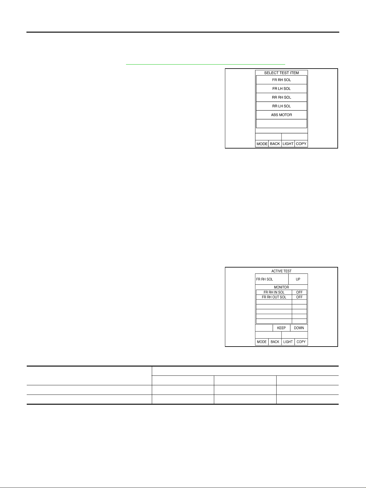
3. The “ SELECT TEST ITEM” screen is displayed.
4. Touch necessary test item.
5. Touch “START” with “MAIN SIGNALS” line inverted.
6. ACTIVE TEST screen will be displayed, so perform the following test.
● Solenoid valve
● ABS motor
NOTE:
● When active tes t is pe r for me d whi l e de pre ssi n g peda l, pe da l dep r ess io n amou nt wil l cha ng e, bu t t hi s
is normal.
● Approximately 10 seconds after operation has begun, “TEST STOP” will be displayed.
● To perform a retest after “TEST STOP” is displayed, touch “BACK” and perform test from step 3.
CONSULT-II Data Link Connector (DLC) Circuit» .
SFIA2085E
SOLENOID VALVE
NOTE:
The example shown is for the front right wheel. The procedure for the other wheels is the same as given
below.
1. For ABS solenoid valve, touch “UP”, “KEEP”, and “DOWN”.
Then use screen monitor to make sure solenoid valve op erates
as shown in Solenoid Valve Operation Chart.
SFIA0678E
Solenoid Valve Operation Chart
Operation
FR RH IN SOL OFF ON ON
FR RH OUT SOL OFF OFF ON*
*: ON for 1 to 2 seconds after the touch, and then OFF
UP KEEP DOWN
ABS solenoid valve
Revision: 2006 July 2006 X-Trail
BRC-22
TROUBLE DIAGNOSIS
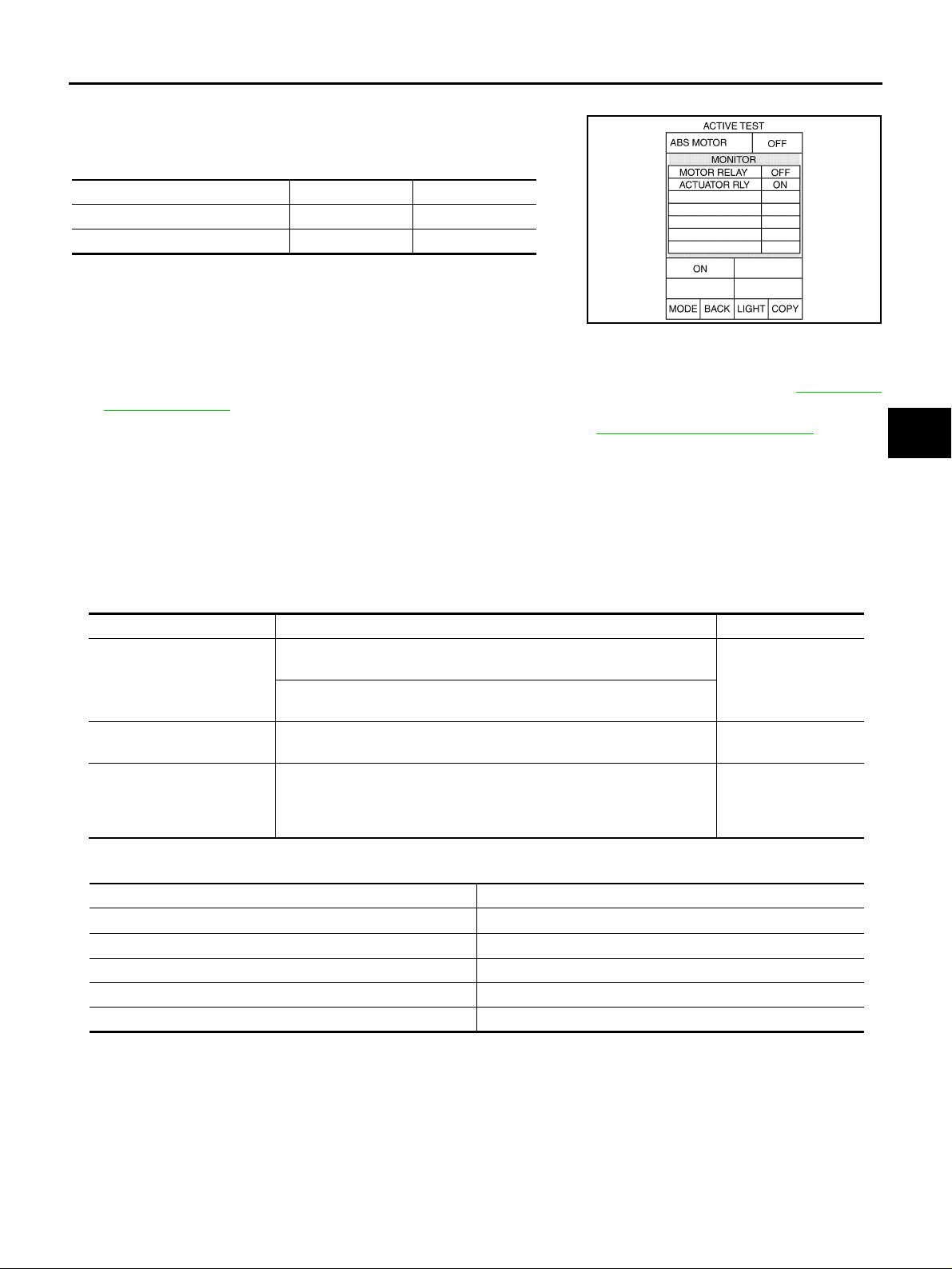
ABS MONITOR
Touch “ON”, “OFF” of the display screen, and make sure if ABS
motor relay and ABS actuator relay are operating as given in the following table.
Operation ON OFF
MOTOR RELA Y ON OFF
ACTUATOR RLY ON ON
[ABS]
A
B
C
SFIA0593E
For Fast and Accurate Diagnosis AFS002M4
PRECAUTIONS FOR DIAGNOSIS
● Be sure to check the procedures of “How to Perform Trouble Diagnosis” in advance. Refer to GI-4, «Gen-
eral Precautions» .
● Always erase memory after completing trouble diagnosis. Refer to BRC-19, «ERASE MEMORY» .
● When checking continuity and voltage between units, be sure to check for disconnection, looseness,
bend, or collapse for connector terminals. Repair or replace applicable part if any non-standard condition
is detected.
● Intermittent malfunctions may be caused by a poor connection in the harness, connectors, and terminals.
Move harnesse s, ha rness co nnector s, an d termin als by hand to make sure all conne ctions are sol id and
undamaged.
● Do not to forcibly extend any connector terminal if a circuit tester is used for the check.
● The symptom shown in the table be low may occur, but the system is operat ing normally.
Symptom Symptom description Result
This is the operation noise of the motor in the actuator, and there may
Motor operation noise
System operation check
noise
ABS operation (Longer stopping distance)
be a slight sound during ABS operation.
Just after the engine starts, the motor operating noise may be hea rd.
This is a normal status of the system operation check.
When engine starts, “click” noise may be heard from engine room. This
is normal status of system operation check.
When driving on roads with a low coefficient of friction, suc h as snow y
roads or gravel roads, the stopping distance is sometimes longer for
vehicles equipped with ABS. Therefore, when driving on such roads,
drive at a sufficiently reduced speed to be safe.
Normal
Normal
Normal
D
E
BRC
G
H
I
J
K
L
ON and OFF Timing for ABS Warning Lamp
×: ON —: OFF
Condition ABS warning lamp
Ignition switch OFF −
When ignition switch is turned ON ×
After ignition switch is turned ON (Whe n syst em is norm al ) −
ABS error ×
EBD error ×
Basic Inspection AFS002M5
BRAKE FLUID LEVEL, LEAKAGE AND BRAKE PAD
1. Check fluid le vel in the brake fluid reservoir tank. Refill the brake fluid if fluid level is low.
2. Check the area around the brake piping and ABS actuator and electric unit (control unit) for leakage. If
leakage or oozi ng is detected, check as follows:
● If ABS actuator and electric unit (control unit) connections are loose, tighten piping to the specified
torque. Check again for leakage, and make sure that there is no fluid leakage.
Revision: 2006 July 2006 X-Trail
BRC-23
M

TROUBLE DIAGNOSIS
[ABS]
● If the flare nuts a t t he co nnec tion s and the thread s of the a ctua tor are dam aged , repl ace t he da mag ed
parts. Then check again for leakage, and make sure that there is no fluid leakage.
● If leakage or oozing is detected on parts other than actuator connections, wipe with a clean cloth and
check again. I f there is still leakage or oozing, replace the damaged part.
● If leakage o r oozing is detected on actuator bo dy, wipe with a clean clot h and chec k again. If t here is
still leakage or oozing, replace ABS actuator and electric unit (control unit).
CAUTION:
ABS actuator and electric unit (control unit) cannot be disassembled.
3. Check brake disc ro to r an d pads . F ron t di sc ro tor: BR-30, «
25, «PAD WEAR INSPECTION» , Rear disk rotor: BR-35, «DISC ROTOR INSPECTION» , Rear pad : BR31, «PAD WEAR INSPECTION» .
POWER SUPPLY CIRCUIT TERMINAL LOOSENESS AND BATTERY
Check battery for looseness on the battery positive/negative terminals and ground connection. Also make sure
that battery voltage does not drop.
INSPECTION OF ABS WARNING LAMP
1. Make sure that when the ignition switch is turned ON, the ABS warning lamp turns on. If it is does not turn
on, perform CAN communication circuit diagnosis. Refer to BRC-31, «
warning lamp if there is no malfunction in CAN commu nication circuit. Refer to BRC-35, «
Lamp Indication Is Not Normal» .
2. Check if the ABS warning lamp turns off after the ignition switch is turned ON after the engine is started. If
it does not turn off, perform self-diagnosis.
3. If ABS warning lamp has not turned off after 10 seconds the engine has been started, perform self-diagnosis of the ABS actuator and electri c un it (co ntro l un it).
4. Always erase the self-diagnostic results after completing self-diagnosis. Refer to BRC-19, «
ORY» .
DISC ROTOR INSPECTION» , Front pad: BR-
CAN Communication» . Check ABS
ABS Warning
ERASE MEM-
Revision: 2006 July 2006 X-Trail
BRC-24

TROUBLE DIAGNOSIS FOR SYSTEM
[ABS]
TROUBLE DIAGNOSIS FOR SYSTEM PFP:00000
Wheel Sensor AFS002M6
INSPECTION PROCEDURE
Check each part according to CONSULT-II self-diagnostic results, and then identify the parts to be replaced.
CAUTION:
Do not check between wheel sensor terminals.
1. CHECK TIRES
Check air pressure, wea r and size.
Are air pressur e, wear and size within standard values?
YES >> GO TO 2.
NO >> Adjust air pressure, or replace tire.
A
B
C
D
2. CHECK SENSOR AND SENSOR ROTOR
● Check sensor rotor for damage.
● Check wheel sensor for damage, disc onnection or looseness.
OK or NG
OK >> GO TO 3.
NG >> Repair wheel sensor mount or replace sensor rotor. Refer to BRC-37, «
36, «WHEEL SENSORS» .
3. CHECK SELF-DIAGNOSTIC RESULTS
Check the self-diagnostic results.
Self-diagnostic results
FR RH SENSOR-1, -2
FR LH SENSOR-1, -2
RR RH SENSOR-1, -2
RR LH SENSOR-1, -2
Is above displayed on self-diagnosis display?
YES >> GO TO 4.
NO >> INSPECTION END
4. CHECK CONNECTOR
SENSOR ROTOR» , BRC-
E
BRC
G
H
I
J
K
L
1. Turn ignition switch OFF and di sconnect ABS actuator and el ectric unit (cont rol unit) conne ctor and malfunctioning wheel sensor connector. Check terminal to see if it is deformed, disconnected, loose, etc., and
repair or replace it if any malfunction condition is found.
2. Reconnect connectors, drive vehicle at 30 km/h (19 MPH) or more for approximately 1 minute, and then
perform self-diagnosis.
Is the result of self-diagnosis normal?
YES >> Connector terminal contact is loose, dama ged, open or shorted.
NO >> GO TO 5.
Revision: 2006 July 2006 X-Trail
BRC-25
M

TROUBLE DIAGNOSIS FOR SYSTEM
5. CHECK WHEEL SENSOR HARNESS
1. Turn ignition switch OFF and disconnect malfunctioning wheel
sensor connector and ABS actuator and electric unit (control
unit) connector.
2. Check continuity between terminals. (Also check continuity
when the steering wheel is turned right and left and when the
sensor harness inside the wh eel house is moved.)
Power supply circuit Signal circuit Gr ound circuit
ABS actuator
and electric
Wheel
Front RH (E17) 24 1 9 2 24, 9
Front LH (E59) 22 1 7 2 22, 7
Rear RH (B130) 28 1 13 2 28, 13
Rear LH (B126) 26 1 11 2 26, 11
unit (control
unit)
harness con-
nector E69
Wheel sensor
(harness con-
nector)
ABS actuator
and electric
unit (control
unit)
harness con-
nector E69
Wheel sensor
(harness con-
nector)
ABS actuator and elec-
tric unit (control unit)
harness connector E69
(signal)
[ABS]
SFIA2015E
Ground
—
Power supply circuit : Continuity should exist.
Signal circuit : Continuity should exist.
Ground circuit : Continuity should not exist.
OK or NG
OK >> GO TO 6.
NG >> Repair or replace harness and connector that have malfunction.
6. CHECK WHEEL SENSOR
1. Replace w heel sensor tha t resulted in malfunction by self-diagnosis.
2. Reconnect conn ectors, dri ve vehicle a t 30 km/h (19 MPH) or mo re for approx imately 1 min ute, and th en
perform self-diagn os is .
Self-diagnostic results
FR RH SENSOR-1, -2
FR LH SENSOR-1, -2
RR RH SENSOR-1, -2
RR LH SENSOR-1, -2
Is above displayed on self-diagnosis display?
YES >> Wheel sensor has malfunction.
NO >>
● Replace ABS actuator and electric unit (control unit).
● Perform to self-diagnosis again, and make sure that the result shows “NO DTC IS DETECTED.
FURTHER TESTING MAY BE REQUIRED”.
Revision: 2006 July 2006 X-Trail
BRC-26

TROUBLE DIAGNOSIS FOR SYSTEM
[ABS]
ABS Actuator and Electric Unit (Control Unit) AFS002M7
INSPECTION PROCEDURE
1. CHECK SELF-DIAGNOSTIC RESULTS
A
Check self-diagn os tic res ults.
Self-diagnostic results
ABS CONTROLLER
Is above displayed on self-diagnosis display?
YES >> Replace ABS actuator and electric unit (control unit), and perform self-diagnosis again.
NO >> INSPECTION END
ABS Actuator and Electric Unit (Control Unit) Power Supply and Ground AFS002M8
INSPECTION PROCEDURE
1. CHECK SELF-DIAGNOSTIC RESULTS
Check self-diagn os tic res ults.
Self-diagnostic results
LOW POWER VOLTAGE
Is above displayed on self-diagnosis display?
YES >> GO TO 2.
NO >> INSPECTION END
2. CHECK CONNECTOR
1. Turn ignition switch OFF, disconnect the ABS actuator and electric unit (control unit) connector, and
check the terminal for deformation, disconnection, looseness, and so on. If there is a malfunction, repair
or replace the terminal.
2. Connect the connector securely and perform se lf-diagnosis again.
Is the result of self-diagnosis normal?
YES >> Connector terminal contact is loose, dama ged, open or shorted.
NO >> GO TO 3.
B
C
D
E
BRC
G
H
I
J
K
Revision: 2006 July 2006 X-Trail
BRC-27
L
M
TROUBLE DIAGNOSIS FOR SYSTEM
[ABS]
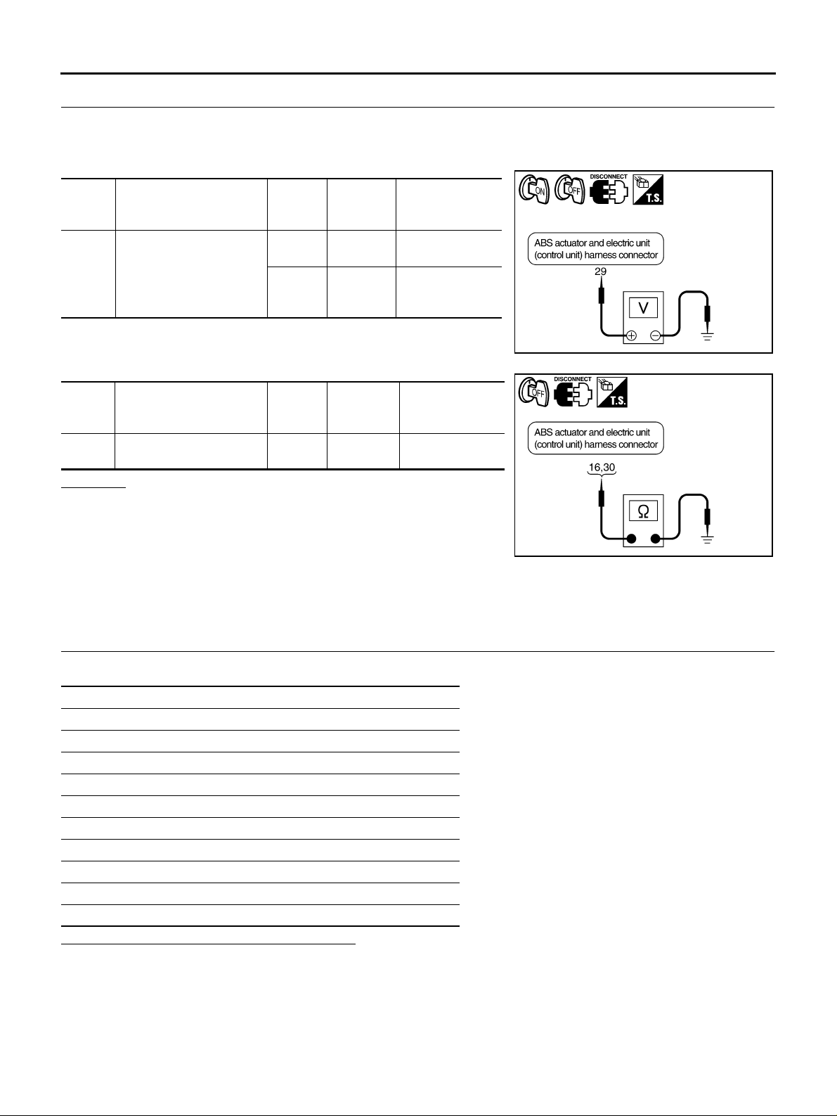
3. CHECK ABS ACTUATOR AND ELECTRIC UNIT (CONTROL UNIT) POWER SUPPLY AND GROUND
1. Turn ignition s witch OFF and disconnect ABS actuator and electric unit (control unit) connector.
2. Turn ignition switch ON or OFF, and then check continuity and voltage between each connector terminal
and ground.
ABS actuator and electric
Signal
Power
supply
Signal
Ground 16, 30 —
unit (control unit)
harness connector E69
29
ABS actuator and electric
unit (control unit)
harness connector E69
Ground
—
—
Ground
Measure-
ment con-
dition
Ignition
switch ON
Ignition
switch
OFF
Measure-
ment con-
dition
Ignition
switch OFF
Volrtage
Battery voltage
(Approx. 12 V)
Approx. 0 V
SFIA2087E
Continuity
Yes
OK or NG
OK >> Check battery for terminal looseness, low voltage, etc. If
any malfunction is found, repair malfunctioning parts.
NG >> Corresponding harness circuit malfunctions. Repair cir-
cuit, and perform self-diagnosis again.
SFIA2089E
ABS Actuator Relay or ABS Motor Relay AFS002M9
INSPECTION PROCEDURE
1. CHECK ABS ACTUATOR AND ELECTRIC UNIT (CONTROL UNIT) POWER SUPPLY AND GROUND
CIRCUIT
Check the self-diag nostic results.
Self-diagnostic results
FR LH IN ABS SOL
FR LH OUT ABS SOL
RR RH IN ABS SOL
RR RH OUT ABS SOL
FR RH IN ABS SOL
FR RH OUT ABS SOL
RR LH IN ABS SOL
RR LH OUT ABS SOL
MAIN RELAY
PUMP MOTOR
Is above displayed on self-diagnosis display?
YES >> GO TO 2.
NO >> INSPECTION END
Revision: 2006 July 2006 X-Trail
BRC-28
TROUBLE DIAGNOSIS FOR SYSTEM
[ABS]
2. CHECK CONNECTOR
1. Turn ignition switch OFF, disconnect the ABS actuator and electric unit (control unit) connector, and check
the terminal for deformation, disconnection, looseness, and so on. If there is a malfunction, repair or
replace the terminal.
2. Connect the connector securely and perform se lf-diagnosis again.
Is the result of self-diagnosis normal?
YES >> Connector terminal contact is loose, dama ged, open or shorted.
NO >> GO TO 3.
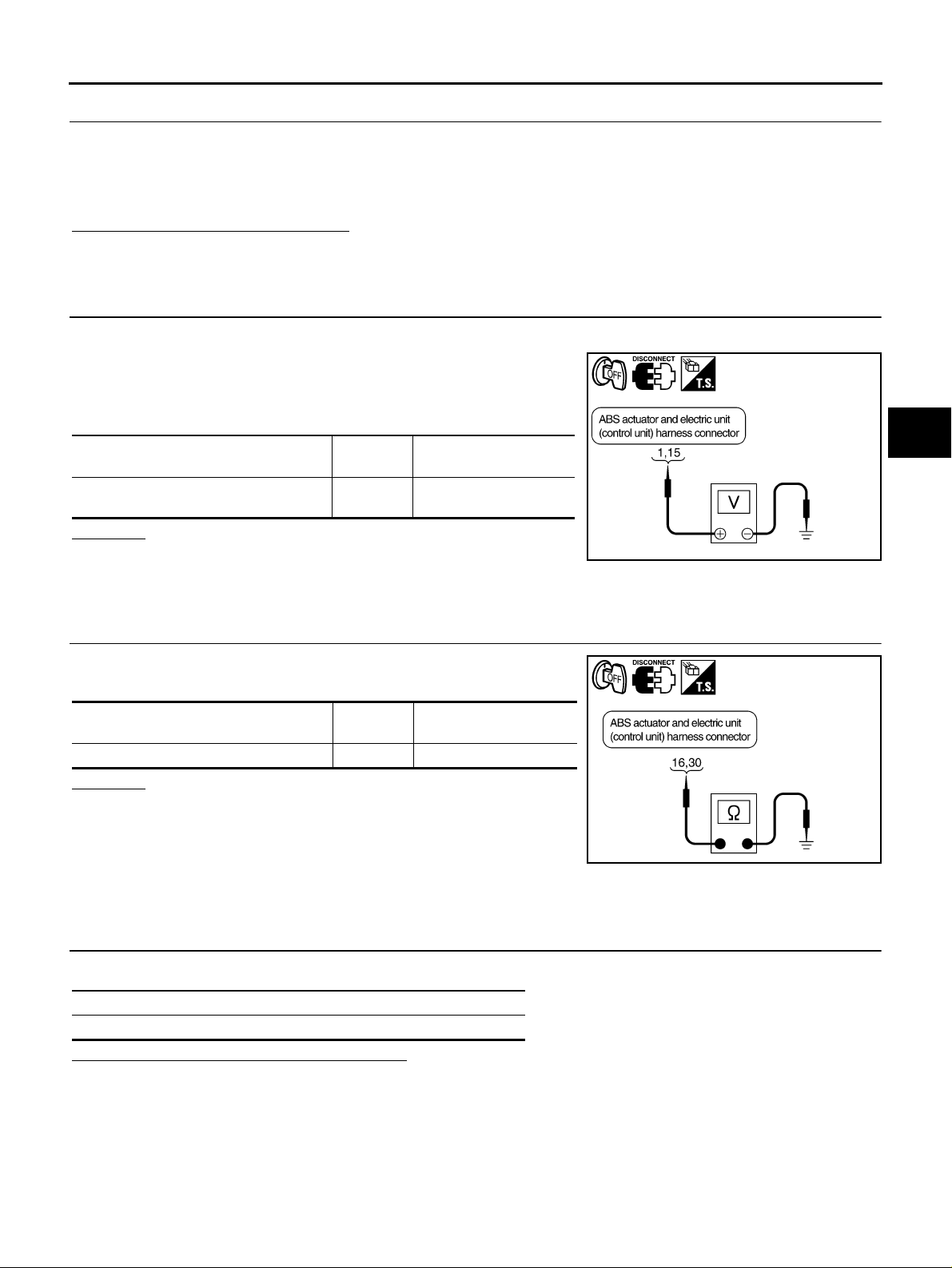
3. CHECK ABS ACTUATOR RELAY OR ABS MOTOR RELAY POWER SUPPLY CIRCUIT
1. Turn ignition switch OFF and disconnect ABS actuator and electric unit (control unit) connector.
2. For the ABS actuator relay, measure voltage between the harness connector terminal 15 and ground. For the ABS motor
relay, measure voltage between the harn ess conn ector term inal
1 and ground.
ABS actuator and electric unit (control
unit) harness connector E69
1, 15 —
OK or NG
OK >> GO TO 4.
NG >> Circuit malfunction between t he battery and ABS actua-
tor and electric unit (control unit). Repair circuit.
Ground Voltage
Battery voltage (Approx.
12 V)
SFIA2110E
A
B
C
D
E
BRC
G
H
4. CHECK ABS ACTUATOR AND ELECTRIC UNIT (CONTROL UNIT) GROUND CIRCUIT
Check continuity between ABS actuator and electric unit (control
unit) harness connector E69 terminals 16, 30 and ground.
ABS actuator and electric unit (control
unit) harness connector E69
16, 30 — Yes
Ground Continuity
OK or NG
OK >> Replace ABS actuator and electric unit (control unit).
NG >> Open or short in harness. Repair or replace the harness,
and perform self-diagnosis again.
SFIA2089E
G Sensor (Only AW D Models) AFS002P9
INSPECTION PROCEDURE
1. CHECK SELF-DIAGNOSTIC RESULTS
Check the self-diagnostic results.
Self-diagnostic results
G SENSOR
Is above displayed on self-diagnosis display?
YES >> GO TO 2.
NO >> INSPECTION END
I
J
K
L
M
Revision: 2006 July 2006 X-Trail
BRC-29
TROUBLE DIAGNOSIS FOR SYSTEM
[ABS]
2. CHECK CONNECTOR
1. Turn ignition switch OFF, disconnect the ABS actuator and electric unit (control unit) and G sensor connector, and check th e t erm in al for def orm at ion , di sc on nect i on , loo sen es s, and so o n. If th er e is a ma lf u nction, repair or replace the terminal.
2. Reconnect connector securely, and perform self-diagnosis.
Is the result of self-diagn os is norm al ?
YES >> Connector terminal contact is loose, damaged, open or shorted.
NO >> GO TO 3.
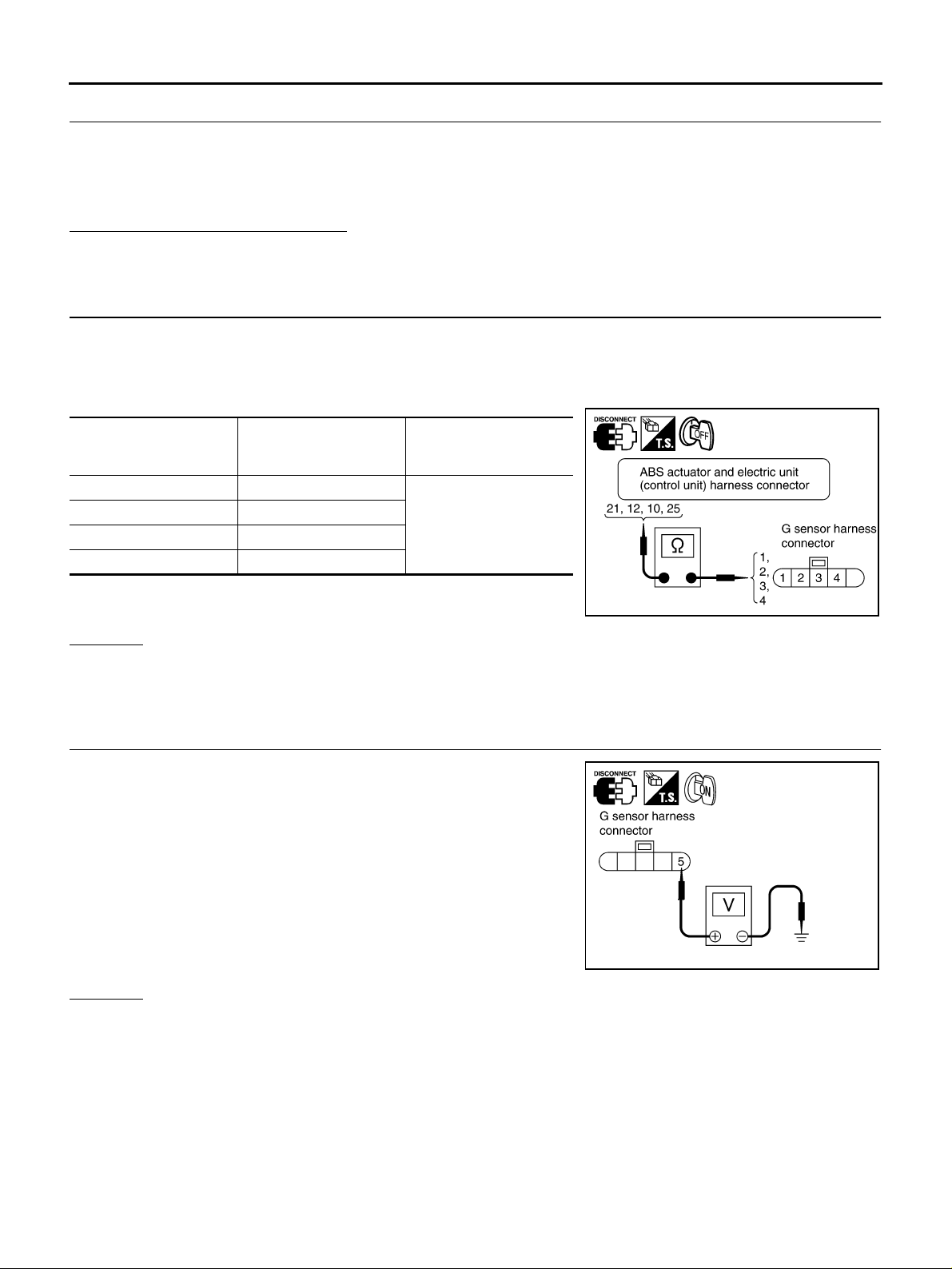
3. CHECK G SENSOR HARNESS
1. Turn ignition switch OFF and disconn ect G sensor and ABS a ctuator and elec tric unit (control u nit) connectors.
2. Check continuity betwee n G sensor harness connecto r M57 and ABS actuator and electric unit (control
unit) harness connector E69.
G sensor harness
connector M57
1 21
2 12
3 10
425
ABS actuator and elec-
tric unit (control unit) har-
ness connector E69
Continuity
Yes
SFIA2438E
OK or NG
OK >> GO TO 4.
NG >> Circuit malfun ction between G sensor and ABS actua tor and electric unit (control un it). Repair
harness.
4. CHECK G SENSOR POWER SUPPLY CIRCUIT
1. Turn ignition sw itch ON.
2. Check voltage between G sensor harness connector M57 terminal 5 and ground.
Voltage : Battery voltage (Approx. 12 V)
SFIA2439E
OK or NG
OK >> GO TO 5.
NG >> G sensor power supply circuit malfunction. Repair circuit.
Revision: 2006 July 2006 X-Trail
BRC-30
Loading…
Мультимедийное руководство на английском языке по техническому обслуживанию и ремонту автомобиля Nissan X-Trail серии T30 с 2001 года выпуска.
- Автор: —
- Издательство: Nissan
- Год издания: 2006
- Страниц: —
- Формат: —
- Размер: 266,9 Mb
Мультимедийное руководство на английском языке по техническому обслуживанию и ремонту автомобиля Nissan X-Trail серии T31 с 2007 года выпуска.
- Автор: —
- Издательство: Nissan
- Год издания: 2007
- Страниц: —
- Формат: —
- Размер: 365,6 Mb
Руководство на английском языке по техническому обслуживанию и ремонту автомобиля Nissan X-Trail серии T32.
- Автор: —
- Издательство: Nissan
- Год издания: —
- Страниц: —
- Формат: —
- Размер: 196,7 Mb
Мультимедийное руководство на английском языке по техническому обслуживанию и ремонту автомобиля Nissan X-Trail серии T31.
- Автор: —
- Издательство: Nissan
- Год издания: —
- Страниц: —
- Формат: ISZ
- Размер: 197,3 Mb
Руководство по техническому обслуживанию и ремонту автомобиля Nissan X-Trail серии T30 2000-2007 годов выпуска с бензиновыми двигателями объемом 2,0/2,5 л.
- Автор: —
- Издательство: Автонавигатор
- Год издания: —
- Страниц: 480
- Формат: —
- Размер: —
Руководство по эксплуатации и ремонту автомобилей Nissan Rogue и Nissan X-Trail серии T31 с 2007 года выпуска с бензиновыми и дизельными двигателями.
- Автор: —
- Издательство: Монолит
- Год издания: —
- Страниц: 430
- Формат: —
- Размер: —
Руководство по эксплуатации и ремонту автомобиля Nissan X-Trail с 2014 года выпуска с бензиновыми и дизельными двигателями.
- Автор: —
- Издательство: Монолит
- Год издания: —
- Страниц: 526
- Формат: —
- Размер: —
Руководство по эксплуатации и техническому обслуживанию автомобиля Nissan X-Trail 2000-2007 годов выпуска.
- Автор: —
- Издательство: MoToR
- Год издания: —
- Страниц: 240
- Формат: —
- Размер: —
Руководство по эксплуатации и техническому обслуживанию автомобиля Nissan X-Trail с 2007 года выпуска.
- Автор: —
- Издательство: Nissan
- Год издания: —
- Страниц: 325
- Формат: PDF
- Размер: 12,0 Mb
Руководство по эксплуатации, техническому обслуживанию и ремонту автомобиля Nissan X-Trail 2001-2007 годов выпуска с бензиновыми и дизельными двигателями.
- Автор: —
- Издательство: Арго-Авто
- Год издания: —
- Страниц: 448
- Формат: —
- Размер: —
Руководство по эксплуатации, техническому обслуживанию и ремонту автомобиля Nissan X-Trail с 2000 года выпуска с бензиновыми двигателями.
- Автор: —
- Издательство: Автонавигатор
- Год издания: 2005
- Страниц: 484
- Формат: PDF
- Размер: 54,0 Mb
Руководство по эксплуатации, техническому обслуживанию и ремонту автомобиля Nissan X-Trail серии T30 с 2000 года выпуска с бензиновым двигателем объемом 2,0 л.
- Автор: —
- Издательство: Автонавигатор
- Год издания: —
- Страниц: 400
- Формат: —
- Размер: —
Руководство по эксплуатации, техническому обслуживанию и ремонту автомобиля Nissan X-Trail серии T31 с 2007 года выпуска с бензиновыми двигателями.
- Автор: —
- Издательство: Автонавигатор
- Год издания: 2008
- Страниц: 375
- Формат: DjVu
- Размер: 12,7 Mb
Руководство по техническому обслуживанию и ремонту автомобиля Nissan X-Trail серии T31 2007-2014 годов выпуска с бензиновыми двигателями объемом 2,0/2,5 л
- Автор: —
- Издательство: Автонавигатор
- Год издания: —
- Страниц: 376
- Формат: —
- Размер: —
Руководство по техническому обслуживанию и ремонту автомобиля Nissan X-Trail серии T31 2007-2010 годов выпуска с бензиновыми двигателями объемом 2,0/2,5 л.
- Автор: —
- Издательство: Автонавигатор
- Год издания: —
- Страниц: 752
- Формат: PDF
- Размер: 95,9 Mb
Руководство по техническому обслуживанию и ремонту автомобиля Nissan X-Trail серии T31 с 2007 года выпуска с бензиновыми двигателями объемом 2,0/2,5 л.
- Автор: —
- Издательство: Автонавигатор
- Год издания: —
- Страниц: 752
- Формат: —
- Размер: —
Руководство по техническому обслуживанию и ремонту автомобиля Nissan X-Trail серии T32 с 2014 года выпуска с бензиновыми и дизельными двигателями.
- Автор: —
- Издательство: Автонавигатор
- Год издания: —
- Страниц: 700
- Формат: —
- Размер: —
Руководство по техническому обслуживанию и ремонту автомобилей Nissan X-Trail серии T32 с 2014 года выпуска с бензиновыми двигателями объемом 2,0/2,5 л.
- Автор: —
- Издательство: Автонавигатор
- Год издания: —
- Страниц: 382
- Формат: —
- Размер: —
Руководство по эксплуатации, техническому обслуживанию и ремонту автомобиля Nissan X-Trail с 2007 года выпуска с бензиновыми двигателями объемом 2,0/2,5 л.
- Автор: —
- Издательство: Мир Автокниг
- Год издания: 2012
- Страниц: 511
- Формат: PDF
- Размер: 104,9 Mb
Руководство по эксплуатации, техническому обслуживанию и ремонту автомобиля Nissan X-Trail с 2015 года выпуска.
- Автор: —
- Издательство: Мир Автокниг
- Год издания: —
- Страниц: 384
- Формат: —
- Размер: —
- Назад
- 1
- 2
- Вперёд
- Страница 1 из 2
Рекомендованные сообщения
-
11
Поделиться сообщением
Ссылка на сообщение
Поделиться на других сайтах
Ссылка перестала работать (файл удален?)
Поделиться сообщением
Ссылка на сообщение
Поделиться на других сайтах
1. Работает.
2. Это скан книжки на русском — она тут еще есть на форуме.
Поделиться сообщением
Ссылка на сообщение
Поделиться на других сайтах
Поделиться сообщением
Ссылка на сообщение
Поделиться на других сайтах
не работает! Нужна как воздух!!!!!
Поделиться сообщением
Ссылка на сообщение
Поделиться на других сайтах
Народ!!! Дайте книжку!!!!
Поделиться сообщением
Ссылка на сообщение
Поделиться на других сайтах
Спасибо. Скачал инструкцию по Т-30 — друг просил,всё читается. Спасибо ещё раз!
Поделиться сообщением
Ссылка на сообщение
Поделиться на других сайтах
Не работает ,пишут вредоносный .Гугл не пускает качать
Поделиться сообщением
Ссылка на сообщение
Поделиться на других сайтах
Не работает ,пишут вредоносный .Гугл не пускает качать
Могу по электронке прислать)
Поделиться сообщением
Ссылка на сообщение
Поделиться на других сайтах
И мне на Т — 30 желательно дизель очень прошу
Поделиться сообщением
Ссылка на сообщение
Поделиться на других сайтах
И мне на Т — 30 желательно дизель очень прошу
Присылайте адрес, куда прислать.
Поделиться сообщением
Ссылка на сообщение
Поделиться на других сайтах
Поделиться сообщением
Ссылка на сообщение
Поделиться на других сайтах
Могу по электронке прислат
и мне можно? за ранние благодарю!
Поделиться сообщением
Ссылка на сообщение
Поделиться на других сайтах
товарищи, ссылка битая уже, можно и мне по электронке если кому не сложно? denko09@mail.ru. заранее спасибо!
Поделиться сообщением
Ссылка на сообщение
Поделиться на других сайтах
Скиньте пожалуйста книгу на T30 на почту naiker2004@mail.ru.
Изменено пользователем naiker
Поделиться сообщением
Ссылка на сообщение
Поделиться на других сайтах
Люди помогите не могу нигде скачать книгу на т30 2002г.в. QR20 помогите, кому не сложно скиньте на электронку asdor27@gmail.com заранее благодарен!
Поделиться сообщением
Ссылка на сообщение
Поделиться на других сайтах
товарищи, ссылка битая уже, можно и мне по электронке если кому не сложно? denko09@mail.ru. заранее спасибо!
Скиньте пожалуйста книгу на T30 на почту naiker2004@mail.ru.
Люди помогите не могу нигде скачать книгу на т30 2002г.в. QR20 помогите, кому не сложно скиньте на электронку asdor27@gmail.com заранее благодарен!
Ребят если вам помогли и дали ссылки на книгу или саму книгу скинули, пришлите и мне пожалуйста.
Заранее спасибо. Мой email: miko1501@mail.ru
Поделиться сообщением
Ссылка на сообщение
Поделиться на других сайтах
Тебе книгу на бензин или дизель?
Поделиться сообщением
Ссылка на сообщение
Поделиться на других сайтах
-
1
Поделиться сообщением
Ссылка на сообщение
Поделиться на других сайтах
В 26.01.2016 в 02:28, rodger711 сказал:
Тебе книгу на бензин или дизель?
Скиньте пожалуйста на дизель. Maximka654@mail.ru
Поделиться сообщением
Ссылка на сообщение
Поделиться на других сайтах
- Назад
- 1
- 2
- Вперёд
- Страница 1 из 2
-
xekxek
Мастер
Команда форума
Эксперт
Модератор- Дневники:
- 0
- Сообщения:
- 2.154
- Рейтинг:
- 293
- Род занятий:
- SRS, Чип-Тюнинг, odo, immo, xekxek2@yandex.ru
- Откуда:
- Москва
- Я езжу на:
- Toyota Land Cruiser 200
Nissan X-Trail T30. Мануал,инструкция,pdf
СКАЧАТЬ…
| Похожие темы: |
|---|
|
Авто глохнет. Nissan wingroad 2003 гв. Двигатель 1.8 |
|
Проблема с двигателем на Nissan Xtrail |
|
Отзыв о Nissan Micra 1.4л (2008 г.в. 40000 км) |
|
Отзыв о Nissan Juke Shiro 1.6л, Вариатор, 2×4 (2012 г.в., 10000 км) |
|
Отзыв о Nissan Leaf 80 кВт, (2013 г.в., 800 км) |
|
Отзыв о Nissan Leaf 80 кВт, (2013 г.в., 3500 км) |
|
Отзыв о Nissan Qashqai+2, 2.0 л, Вариатор, 4х4 (2013 г.в., 25000 км) |