
1 Operating Manual Optimal Automated Distillation STANDARDS ASTM D86 — IP EN ISO DIN NF M JIS K2254 ASTM D850 — ASTM D I…
OptiDist
Operating Manual
Optimal Automated Distillation
STANDARDS ASTM D86 — IP 123 — EN ISO 3405 — DIN51 751 — NF M07-002 — JIS K2254 ASTM D850 — ASTM D1078 — IP 195 — ISO 918
OptiDist
PAC 8824 Fallbrook Drive Houston, TX 77064 USA
Web:
http://www.paclp.com
Phone:
USA France Germany Singapore
+1 281 940 1803 +33 231 264 300 +49 9343 6400 +65 6742 8453
Fax:
USA France Germany Singapore
+1 281 580 0719 +33 231 266 293 +49 9343 640 101 +65 6742 8759
E-Mail:
Sales:
USA France Germany Singapore
mailto:[email protected] mailto:[email protected] mailto:[email protected] mailto:[email protected]
E-Mail:
Service:
USA France Germany Singapore
mailto:[email protected] mailto:[email protected] mailto:[email protected] mailto:[email protected]
Manual PN: 8001-004-01E
Page 2
OptiDist Operating Manual
OptiDist
PAC© copyright The PAC OptiDist analyzers and this manual are protected by copyright. Reproduction of the unit will result in prosecution. All rights to the manual are reserved. Reproduction in any form, including in the form of excerpts, shall require written permission from the copyright holder. This product is covered by several pending patents.
OptiDist
Software(c) 2006, PAC
This present software is owned by PAC with the « Agence pour la Protection des Programmes, 249 rue de Crimée — 75019 Paris. It is protected in France by the « Code de Propriété Intellectuelle » laws and internationally by international treaty provisions, and all other applicable national laws. It must not be copied, reproduced, adapted, translated, rented or disassembled. This also applies to the accompanying manuals. IDDN pending INFORMATION Information in this document is subject to change without notice and does not represent a commitment on the part of PAC. PAC provides this document “as is”, without warranty of any kind, either expressed or implied, including, but not limited to, the particular purpose. PAC may make improvements and/or changes in this manual or in the product(s) and/or the program (s) described in this manual at any time. This product could include technical inaccuracies or typographical errors. Changes are periodically made to the information herein; these changes may be incorporated in new editions of the publication. Reproduction of any part of this manual without express written permission is forbidden.
PAC and PAC logo are trademarks of PAC SA. Other brands and trademarks are the property of their respective owners.
1st Edition: January 2007 Translation in foreign local language (other than English, French or German) Translation in other language than English, French or German have no contractual value and have been performed under responsibility of the local distributor. In any case the reference of the present literature will be the English release provided under PAC copyright.
OptiDist Operating Manual
Page 3
OptiDist
Correct disposal of Waste Electrical and Electronic Equipment in the end-of life Applicable in the European Union and countries with separate collection systems
other
European
This product is designed for exclusive professional use by commercial companies. This marking shown on the product or its literature, indicates that it should not be disposed with other household wastes at the end of its working life. To prevent possible harm to the environment or human health from uncontrolled waste disposal, please separate this from other types of wastes and recycle it responsibly to promote the sustainable reuse of material resources. Business users should contact the producer or the importer and check the terms and conditions of the purchase contract. If you have a separate agreement with your producer or your importer on the end-of-life disposal in a way that you will care for disposal by your own, would you please ensure an environmentally sound disposal according to the legal regulations for electric and electronic waste equipment in your country. This product should not be mixed with other commercial wastes for disposal. The above WEEE-symbol is the official marking for equipment under the WEEE-scope. In some EC-Member states «pure B2B equipment» is not necessarily marked with the wastebin-symbol. To provide a homogenous EC-wide procedure, PAC however uses the marking in all EC-Member states.
Page 4
OptiDist Operating Manual
OptiDist
Reserved for public relations department N° ………………………….. Date ………………………..
CUSTOMER REPORT PURPOSE I wish to
Report an error Submit a suggestion / a comment Get more information
In the area of
Hardware
Software
Manual
ANALYZER ENVIRONMENT (please be complete) • HARDWARE Options :
Type of Analyzer: OptiDist Serial N° : …………………………………………… Built-in printer
External printer
Status indicator beacon
Ambient T° Probe
VOC
Other : ……………………………………………… • SOFTWARE
Version : ………………………………………………..
ATTACHED SHEETS Listing
Diskette
Drawing
Text
Other
PROBLEM DESCRIPTION / COMMENTS
SUBMITTED BY Name : Company : Address : Phone :
Fax :
Date:
Send this report to your local sales office (see page 2).
OptiDist Operating Manual
Page 5
OptiDist
Revision Tracking
Revision
§ concerned
Modification descriptive
Date
Original issue
01/06/07
Part I § 3.3.7
Installation of the Automatic Dry Point Kit and Holder
index 1.30A
1.36B
Page 6
Part I § 3.3.9
Installation and Connection of the Status Indicator Beacon
Part I § 5.5
Modification of the default-activated access level at power on
Part II § 2.2.2
Modification of the vapor probe location and fixing procedure
Part II § 2.2.4
Adjustment of the vapor probe in the dry point stopper
Part III § 2.4
List of ASTM D1078 / D850 compounds
Part III § 4
Quality Control Database
Part IV § 5.3.2
Data transfer and firmware update by USB key
Part IV § 6.2
Update of the alarm list and troubleshooting guide
08/23/07
OptiDist Operating Manual
OptiDist
Caution
This analyzer has been carefully designed, manufactured and inspected for quality. It has been equipped with a number of safety features. However, the use of this analyzer may involve the handling of solvents, chemicals, and other potentially dangerous flammable, toxic, etc.) materials. Please exercise caution when- handling these materials while operating the analyzer. Please: read the manual wear proper protective clothing perform all suggested service procedures use care to prevent accidents. The manufacturer accepts no responsibility for any damage or liability arising from the use of analyzers. Use of Non-PAC Products and Accessories. Defects or damage that result from the use of Non-PAC branded or certified Products, Accessories, Software or other peripheral equipment are excluded from warranty.
OptiDist Operating Manual
Page 7
OptiDist
Page intentionally blank.
Page 8
OptiDist Operating Manual
OptiDist
Contents PART 1 OPTIDIST GENERAL INFORMATION………………………………………………………………………………….. 1-13 CHAPTER 1 INTRODUCTION 1-15 1.1 About this Manual ………………………………………………………………………………………………………………. 1-15 1.1.1 Content of this Manual……………………………………………………………………………………………………. 1-15 1.1.2 Typographical Conventions …………………………………………………………………………………………….. 1-15 1.1.3 Meaning of Symbols………………………………………………………………………………………………………. 1-15 1.2 Careful Use of Testing and Cleaning Materials ……………………………………………………………………….. 1-15 CHAPTER 2 PRESENTATION OF THE OPTIDIST AUTOMATED DISTILLATION ANALYZER 1-16 2.1 Product Overview……………………………………………………………………………………………………………….. 1-16 2.2 Benefits and Features …………………………………………………………………………………………………………. 1-17 2.3 General Scope …………………………………………………………………………………………………………………… 1-17 2.4 Terminology ………………………………………………………………………………………………………………………. 1-18 2.5 Abbreviations …………………………………………………………………………………………………………………….. 1-18 2.6 Specifications …………………………………………………………………………………………………………………….. 1-19 CHAPTER 3 UNPACKING AND INSTALLATION 1-21 3.1 Pre-Installation Considerations — Technical Specifications ………………………………………………………… 1-21 3.2 Care in Unpacking………………………………………………………………………………………………………………. 1-22 3.3 Installation of the OptiDist ………………………………………………………………………………………………….. 1-22 3.3.1 OptiDist Setup ……………………………………………………………………………………………………………. 1-22 3.3.2 Main Power Connection …………………………………………………………………………………………………. 1-22 3.3.3 CO2 Gas Connection ……………………………………………………………………………………………………… 1-23 3.3.4 OptiDist / PC Connection……………………………………………………………………………………………… 1-23 3.3.4.1. Optional External PC Control……………………………………………………………………………………. 1-23 3.3.4.2. RS 232C serial link …………………………………………………………………………………………………. 1-23 3.3.5 Flask Stopper Holder……………………………………………………………………………………………………… 1-23 3.3.6 Probe Connection………………………………………………………………………………………………………….. 1-23 3.3.6.1. Pt100 Vapor Probe …………………………………………………………………………………………………. 1-23 3.3.6.2. Ambient Temperature Probe ……………………………………………………………………………………. 1-23 3.3.7 Installation of the Automatic Dry Point Kit and Holder …………………………………………………………. 1-24 3.3.8 VOC Control Option Connection ……………………………………………………………………………………… 1-24 3.3.9 Installation and Connection of the Status Indicator Beacon …………………………………………………. 1-24 3.3.10 Connection of an Optional External Printer ……………………………………………………………………….. 1-25 3.3.11 Connection of the Optional Bar Code Reader ……………………………………………………………………. 1-25 3.4 Power-On Procedure ………………………………………………………………………………………………………….. 1-26 3.4.1 Switching On ………………………………………………………………………………………………………………… 1-26 3.4.2 Heat Exchanging Liquid (Level Checking and Recommendations) ……………………………………….. 1-26 3.4.3 The Welcome Screen…………………………………………………………………………………………………….. 1-26 3.4.4 PAC Addresses Screen………………………………………………………………………………………………….. 1-27 3.4.5 Self Diagnostic Screen …………………………………………………………………………………………………… 1-27 3.4.6 Analyzer Calibration ………………………………………………………………………………………………………. 1-27 CHAPTER 4 UNIT DESCRIPTION 1-28 4.1 Views………………………………………………………………………………………………………………………………… 1-29 4.1.1 Front View ……………………………………………………………………………………………………………………. 1-29 4.1.2 Rear View…………………………………………………………………………………………………………………….. 1-30 4.1.3 Left Side View ………………………………………………………………………………………………………………. 1-30 4.1.4 Right Side View …………………………………………………………………………………………………………….. 1-31 4.2 Flask Heater Assembly ……………………………………………………………………………………………………….. 1-32 4.2.1 Description …………………………………………………………………………………………………………………… 1-32 4.2.2 Self-positioning Flask Heater Platform ……………………………………………………………………………… 1-33 4.2.3 Heating Regulation………………………………………………………………………………………………………… 1-33 4.2.4 Heating Element……………………………………………………………………………………………………………. 1-33 4.2.5 Flask Cooling………………………………………………………………………………………………………………… 1-33 4.2.6 Safety Features …………………………………………………………………………………………………………….. 1-33 4.3 Distillation Flask …………………………………………………………………………………………………………………. 1-34 4.4 Flask Stopper …………………………………………………………………………………………………………………….. 1-34 4.5 Vapor Temperature Probe……………………………………………………………………………………………………. 1-35 4.6 Condenser Tube Regulation ………………………………………………………………………………………………… 1-35 4.7 Cooling Unit……………………………………………………………………………………………………………………….. 1-36 4.8 The Receiving Chamber………………………………………………………………………………………………………. 1-36 4.9 Receiver Cylinder……………………………………………………………………………………………………………….. 1-38
OptiDist Operating Manual
Page 9
OptiDist 4.10 Touch-Screen Display………………………………………………………………………………………………………..1-39 4.10.1 Touch Screen Display ……………………………………………………………………………………………………..1-39 4.10.2 Summary of Possibilities ………………………………………………………………………………………………….1-39 4.10.3 Handling Precautions for LCD Touch Screen ……………………………………………………………………..1-39 4.10.4 Storage …………………………………………………………………………………………………………………………1-39 4.10.5 Setting…………………………………………………………………………………………………………………………..1-40 4.10.6 The Virtual Keypad………………………………………………………………………………………………………….1-40 4.10.7 The Virtual Keyboard ………………………………………………………………………………………………………1-41 4.11 Connection Ports……………………………………………………………………………………………………………….1-42 4.12 Optional Features………………………………………………………………………………………………………………1-43 4.12.1 Ambient Temperature Probe…………………………………………………………………………………………….1-43 4.12.2 125 and 200 cc Automatic Dry Point Detection Kit……………………………………………………………….1-43 4.12.3 Accessories for “10 % (V/V) Distillation Residue” with 200ml ………………………………………………..1-43 4.12.4 Optional External PC Control: HLIS-32® or ALAN® …………………………………………………………….1-44 4.12.5 Status Indicator Beacon …………………………………………………………………………………………………..1-44 4.12.6 Built-in Printer ………………………………………………………………………………………………………………..1-44 4.12.7 External Printer ………………………………………………………………………………………………………………1-44 4.12.8 Bar Code Reader ……………………………………………………………………………………………………………1-45 4.12.9 “Doctor Box” …………………………………………………………………………………………………………………..1-45 4.12.10 VOC Control………………………………………………………………………………………………………………..1-45 CHAPTER 5 SAFETY FEATURES 1-46 5.1 Alarms………………………………………………………………………………………………………………………………..1-46 5.2 Power Consuming Devices……………………………………………………………………………………………………1-46 5.3 Emergency Stop Button ………………………………………………………………………………………………………..1-47 5.4 Automatic Fire Extinguisher System ……………………………………………………………………………………….1-47 5.5 Access Levels ……………………………………………………………………………………………………………………..1-48 5.6 Passive Safety — Receiver Liquid Spillage Trap ………………………………………………………………………..1-48 PART 2 BASIC USE OF OPTIDIST……………………………………………………………………………………………………2-49 CHAPTER 1 INTRODUCTION 2-51 1.1 Use As Intended ………………………………………………………………………………………………………………….2-51 1.2 Description of an Automatic Distillation Run …………………………………………………………………………….2-51 1.3 Description of the “Distillation Product” ……………………………………………………………………………………2-51 CHAPTER 2 INITIATING A DISTILLATION TEST 2-52 2.1 Sampling, Storage and Sample Conditioning according to ASTM D86 ………………………………………..2-52 2.1.1 Sampling Recommendations ……………………………………………………………………………………………2-52 2.1.2 Sample Storage Recommendations…………………………………………………………………………………..2-52 2.1.3 Sample Conditioning Recommendations Prior to Analysis ……………………………………………………2-53 2.1.4 Wet Samples………………………………………………………………………………………………………………….2-53 2.2 Test Preparation ………………………………………………………………………………………………………………….2-53 2.2.1 Cleaning………………………………………………………………………………………………………………………..2-53 2.2.2 Preparation of the Analyzer and Accessories ……………………………………………………………………..2-54 2.2.3 Adjustment of the Vapor Probe in the Flask Stopper ……………………………………………………………2-55 2.2.4 Adjustment of the Vapor Probe in the Dry Point Stopper ………………………………………………………2-55 2.3 The OptiDist Run / Start & Display Screen…………………………………………………………………………….2-56 2.3.1 Part 1 shows the status of the unit and is always visible:………………………………………………………2-56 2.3.2 Part 2 is the Operation and Reporting Screen …………………………………………………………………….2-57 2.3.3 Part 3 is the Main Menu …………………………………………………………………………………………………..2-57 2.4 The Start Guide (Assisted Test Starting Procedure)………………………………………………………………….2-58 2.5 The Normal Test Starting Mode……………………………………………………………………………………………..2-63 2.5.1 Selection of the Operator Name in the Pre-stored List / Manual Entry…………………………………….2-63 2.5.2 Selection of the Sample Name in the Pre-stored List / Manual Entry………………………………………2-64 2.5.3 Selection of a Product in the Pre-stored List ……………………………………………………………………….2-64 2.5.4 Addition of a comment …………………………………………………………………………………………………….2-65 2.6 Quick Test Starting Mode ……………………………………………………………………………………………………..2-66 2.7 Flask and Receiver set up …………………………………………………………………………………………………….2-67 2.7.1 Preparing and Inserting the Sample and Receiver……………………………………………………………….2-67 2.7.1.1. Filling the Receiver Cylinder………………………………………………………………………………………2-67 2.7.1.2. Filling and Installing the Flask ……………………………………………………………………………………2-67 2.7.1.3. Installing the Receiver Cylinder………………………………………………………………………………….2-68 2.7.2 Set-up of the Receiver Chamber Temperature ……………………………………………………………………2-68 2.7.3 Scan of the charge volume ………………………………………………………………………………………………2-69 2.8 Test Progressing………………………………………………………………………………………………………………….2-70 2.8.1 Test Starting…………………………………………………………………………………………………………………..2-70 2.8.2 Sample Distillation…………………………………………………………………………………………………………..2-70 2.8.3 End of test and Cooling……………………………………………………………………………………………………2-71
Page 10
OptiDist Operating Manual
OptiDist 2.8.4 Residue Measurement …………………………………………………………………………………………………… 2-71 2.8.4.1. Automatic input………………………………………………………………………………………………………. 2-71 2.8.4.2. Manual input ………………………………………………………………………………………………………….. 2-71 2.8.4.3. Measured by the analyzer ……………………………………………………………………………………….. 2-71 2.9 Manual Test Stop ……………………………………………………………………………………………………………….. 2-71 CHAPTER 3 DISPLAYING AND PRINTING RESULTS 2-72 3.1 Displaying of Results…………………………………………………………………………………………………………… 2-72 3.2 Printing of Results ………………………………………………………………………………………………………………. 2-73 CHAPTER 4 ALARM TREATMENT AND DESCRIPTION 2-74 4.1 Alarm Processing ……………………………………………………………………………………………………………….. 2-74 4.2 Alarm Displaying and Stopping …………………………………………………………………………………………….. 2-74 4.3 Alarm Review …………………………………………………………………………………………………………………….. 2-74 PART 3 ADVANCED USE OF OPTIDIST…………………………………………………………………………………………. 3-75 CHAPTER 1 INTRODUCTION 3-77 CHAPTER 2 TEST SET-UP 3-77 2.1 List of pre stored Operator Names ………………………………………………………………………………………… 3-77 2.1.1 Displaying the Operator Name List…………………………………………………………………………………… 3-77 2.1.2 Addition of a New Name in the pre-stored List …………………………………………………………………… 3-78 2.1.3 Removal of a Name from the pre stored List ……………………………………………………………………… 3-78 2.1.4 Modification of a Name in the pre stored List …………………………………………………………………….. 3-78 2.2 Product Data Base ……………………………………………………………………………………………………………… 3-79 2.3 List of Standard Test Methods ……………………………………………………………………………………………… 3-82 2.4 List of ASTM D1078 / D850 Compounds ……………………………………………………………………………….. 3-84 2.5 List of Report Profiles ………………………………………………………………………………………………………….. 3-85 CHAPTER 3 ANALYZER SET-UP 3-88 CHAPTER 4 QUALITY CONTROL DATABASE 3-90 4.1 Displaying the Spreadsheet QC Database……………………………………………………………………………… 3-90 4.2 Selection of the QC Sample Database to Display ……………………………………………………………………. 3-91 4.3 Selection of the Specified Result…………………………………………………………………………………………… 3-91 4.4 Displaying the Graphic QC Database ……………………………………………………………………………………. 3-92 4.5 Removal of a test from a QC sample database……………………………………………………………………….. 3-92 4.6 Modification of Specified Results in a QC Sample Database …………………………………………………….. 3-93 4.7 Removal of a QC sample database ………………………………………………………………………………………. 3-93 PART 4 OPTIDIST MAINTENANCE …………………………………………………………………………………………………. 4-95 CHAPTER 1 MEASUREMENT CHECKS 4-97 1.1 Frequency of Measurement Checks ……………………………………………………………………………………… 4-97 1.2 Displaying Current Readings………………………………………………………………………………………………… 4-98 1.3 Measurement Checking Procedures ……………………………………………………………………………………… 4-99 1.3.1 Barometric Pressure………………………………………………………………………………………………………. 4-99 1.3.2 Vapor Temperature Measurement Circuit …………………………………………………………………………. 4-99 1.3.3 Heater Temperature ………………………………………………………………………………………………………. 4-99 1.3.4 Condenser Bath Temperature ……………………………………………………………………………………….. 4-100 1.3.5 Receiving Chamber Temperature ………………………………………………………………………………….. 4-100 1.3.6 Volume in the Receiver ………………………………………………………………………………………………… 4-100 CHAPTER 2 CALIBRATION OF THE ANALYZER 4-101 2.1 Barometric Pressure …………………………………………………………………………………………………………. 4-102 2.2 Vapor Temperature Measurement System …………………………………………………………………………… 4-103 2.2.1 Electronic Circuit …………………………………………………………………………………………………………. 4-103 2.2.2 Vapor Probe Table ………………………………………………………………………………………………………. 4-104 2.2.3 Unit Temperature Correction Table ………………………………………………………………………………… 4-106 2.3 Receiving Chamber Volume Measurement…………………………………………………………………………… 4-107 2.4 Flask Heater Temperature …………………………………………………………………………………………………. 4-110 2.5 Optimizer…………………………………………………………………………………………………………………………. 4-111 2.6 Touch Screen…………………………………………………………………………………………………………………… 4-112 2.6.1 Calibration of the Cursor Sensitivity Area ………………………………………………………………………… 4-112 2.6.2 Adjustment of the LCD Screen Backlight…………………………………………………………………………. 4-112 2.7 Test Start Refusal …………………………………………………………………………………………………………….. 4-113 2.8 Calibration Ticket Printing ………………………………………………………………………………………………….. 4-113 CHAPTER 3 THE SERVICE FUNCTIONS OF THE “PARAMETER” MAIN MENU 4-114 CHAPTER 4 DIAGNOSTIC FUNCTIONS 4-115 4.1 Various Individual Component Diagnostic Function ……………………………………………………………….. 4-115 4.1.1 Activation of the Diagnostic Mode ………………………………………………………………………………….. 4-115 4.1.2 Diagnostic of the Flask Heating Block …………………………………………………………………………….. 4-116 4.1.2.1. Down Solenoid of the Heating Block ……………………………………………………………………….. 4-116 4.1.2.2. Cooling Fan of the Flask Heating Block……………………………………………………………………. 4-116 4.1.2.3. Flask Heating Element ………………………………………………………………………………………….. 4-117
OptiDist Operating Manual
Page 11
OptiDist 4.1.3 Diagnostic of the Volume Measurement …………………………………………………………………………..4-117 4.1.3.1. Level Follower Motor ………………………………………………………………………………………………4-117 4.1.3.2. Optical Detectors for Volume Measurement (Level Follower Fork) ………………………………..4-117 4.1.4 Diagnostic of the Condenser Bath Circuit …………………………………………………………………………4-118 4.1.4.1. Heater ………………………………………………………………………………………………………………….4-118 4.1.4.2. Cooling Solenoid Valve …………………………………………………………………………………………..4-118 4.1.4.3. Optional Boost Heater …………………………………………………………………………………………….4-118 4.1.4.4. Pump……………………………………………………………………………………………………………………4-119 4.1.5 Diagnostic of the Receiving chamber……………………………………………………………………………….4-119 4.1.5.1. Receiving chamber Heater………………………………………………………………………………………4-119 4.1.5.2. Cooling Pump………………………………………………………………………………………………………..4-119 4.1.5.3. Fan ………………………………………………………………………………………………………………………4-119 4.1.5.4. VOC Pump (optional) ……………………………………………………………………………………………..4-120 4.1.5.5. Drop Detection Optical Fork …………………………………………………………………………………….4-120 4.1.6 Diagnostic of the Cooling Unit: the Exchanger…………………………………………………………………..4-120 4.1.7 End of Diagnostic ………………………………………………………………………………………………………….4-120 4.2 Connection and Use of the “Doctor Box” ……………………………………………………………………………….4-121 4.2.1 Operation of supply circuits…………………………………………………………………………………………….4-121 4.2.1.1. Fuses …………………………………………………………………………………………………………………..4-121 4.2.1.2. Rapid diagnostic…………………………………………………………………………………………………….4-122 4.2.2 Voltages ………………………………………………………………………………………………………………………4-123 4.2.2.1. Checking Voltages …………………………………………………………………………………………………4-123 4.2.2.2. Measuring Voltages………………………………………………………………………………………………..4-123 CHAPTER 5 MAINTENANCE 4-124 5.1 Reminder on Frequency of Measurement Checks and Calibration…………………………………………….4-124 5.2 Routine Maintenance ………………………………………………………………………………………………………….4-124 5.3 Analyzer Update ………………………………………………………………………………………………………………..4-125 5.3.1 Firmware and Hardware Version……………………………………………………………………………………..4-125 5.3.2 Data Transfer and Firmware Update by USB key ………………………………………………………………4-126 5.4 Checking and Replacement of the Condenser Tube / Flask Silicone Tube …………………………………4-128 5.5 Checking and Replacement of the Rubber Cap on the Exit of the Condenser Tube …………………….4-128 5.6 Checking and Replacement of the Stopper Seals …………………………………………………………………..4-128 5.7 Checking and Replacement of the Stopper Tip ………………………………………………………………………4-129 5.8 Replacing the Vapor Probe………………………………………………………………………………………………….4-129 5.9 Replacing the Dry Point Thermocouple …………………………………………………………………………………4-129 5.10 Draining the Receiving Chamber Spillage Trap ……………………………………………………………………4-129 5.11 Testing the Fire Extinguisher Solenoid Valve and Flame Detector ………………………………………….4-130 5.11.1 Frequency ……………………………………………………………………………………………………………………4-130 5.11.2 Test Procedure …………………………………………………………………………………………………………….4-130 5.12 Connection of an External Fire Alarm Device ………………………………………………………………………4-130 5.13 Disassembling/Reassembling the OptiDist Housing……………………………………………………………4-132 5.13.1 Disassembling / Reassembling the Flask Heater Assembly Housing ……………………………………4-132 5.13.2 Disassembling / Reassembling the Analyzer Main Housing ………………………………………………..4-132 5.14 Control of the Heating Element Coil ……………………………………………………………………………………4-133 5.15 Replacing the Heating Element………………………………………………………………………………………….4-133 5.16 Servicing the Cooling System ……………………………………………………………………………………………4-134 5.16.1 Checking the coolant level — Filling…………………………………………………………………………………..4-134 5.16.2 Cleaning the condenser of the cooling unit ……………………………………………………………………….4-135 CHAPTER 6 TROUBLESHOOTING 4-136 6.1 Frequently Asked Questions………………………………………………………………………………………………..4-136 6.2 List of Alarm Messages and Troubleshooting …………………………………………………………………………4-137 APPENDICES ……………………………………………………………………………………………………………………………………141 APPENDIX A — PRINTING TYPE EXAMPLES 143 A.1 — 40 Column Result Printout …………………………………………………………………………………………………..143 A.2 — 40 Column Calibration Ticket Printout……………………………………………………………………………………144 APPENDIX B — INTERFACE FEATURES 145 B.1 — Outlet connector broaching ………………………………………………………………………………………………….145 B.2 — Communication protocols…………………………………………………………………………………………………….146 INDEX INDEX
……………………………………………………………………………………………………………………………………….147 4-149
SPARE PART LIST……………………………………………………………………………………………………………. 8005-004 -01E
Page 12
OptiDist Operating Manual
Part 1
OptiDist Operating Manual
OptiDist General Information
Page 1-13
OptiDist
Page intentionally blank.
Page 1-14
OptiDist Operating Manual
Introduction
Chapter 1 Introduction 1.1 About this Manual
1.1.1
Content of this Manual
This manual comprises four main parts entitled: Part I – OptiDist General Information Part II — Basic Use of OptiDist Part III — Advanced Use of OptiDist Part IV — OptiDist
Maintenance
The first part (this part) will help you to become familiar with your new OptiDist
Analyzer.
The second part will enable the operator, in just few steps, to activate preinstalled products and confidently carry out an initial test to determine the distillation characteristics of a hydrocarbon in accordance with consensus group standards. The third part makes it possible to use the OptiDist potential to its full. This section is intended for the knowledgeable user who is familiar with hydrocarbon distillations. In any case, the sensitive parts of the OptiDist software, those linked to the configuration of these advanced capabilities, can be read-and writeprotected by a system of passwords chosen by the user. The fourth part addresses OptiDist maintenance and explains in detail the various maintenance and update operations to be performed on the OptiDist analyzer.
1.1.2
Typographical Conventions
Convention
Meaning
Bold
Important words or phrases
Bold Italics
Menus
Bold + SMALL CAPITALS
Menu Keys
1.1.3
Meaning of Symbols
Actions to be done
Note:
Important comment.
CAUTION!
Call for particular care
Referral
Referral to a particular document (i.e. Standard Test Methods) or another manual.
1.2 Careful Use of Testing and Cleaning Materials The users are assumed to be familiar with the handling of hydrocarbon products and that they are thus aware of the dangers and risks that attach to them.
OptiDist Operating Manual
Page 1-15
OptiDist
Chapter 2 Presentation of the OptiDist Automated Distillation Analyzer
2.1 Product Overview
The new PAC OptiDist is an automated and user-friendly distillation analyzer born of a combination of customer feedback and over eighty years combined experience of the companies Walter Herzog and ISL in designing and manufacturing automatic distillation equipment. Utilizing advanced technology and a high quality design, the OptiDist allows laboratory analysts of all skill levels to perform automatic atmospheric pressure distillations, which comply with consensus group standard test methods, on a wide variety of liquid hydrocarbon materials. Typically, these distillations are used to characterize the tendency of a hydrocarbon fuel to vaporize. Vaporization characteristics are a critical measure of overall fuel safety and performance. According to strict guidelines and protocols described in these standard test methods, a given volume of sample is distilled under appropriate conditions according to its group or class. During the analysis, temperature, volume of condensate and time are precisely and systematically recorded. The resulting data is used to determine the materials distillation (or volatility) characteristics. Test results are commonly expressed as percent evaporated or percent recovered (according to the sample group) versus corresponding temperature. The instrument offers several modes of operation that employ the power of automation to significantly increase test productivity (sample throughput) while also improving repeatability and reproducibility. In all modes, a large graphical touch screen interface provides guidance regarding instrument set up and standard test method requirements that can prove ideal for new or untrained staff that have small exposure to the distillation test procedure. Each mode is designed to operate with minimal test programming, while supplying quick, reliable boiling range characteristics of a product often giving results in compliance with a wide range of standard methods from the first analysis. Simple, straightforward operation involves selecting a sample ID or a product from pre-stored lists following the group in which the sample falls and pressing the “Start” button when a flask filled with test specimen is placed on the instrument. No special programming of test conditions is required. To determine the optimal heating curve, the OptiDist employs the unique Optimizer technology. The optimizer technology assures perfect repeatability of distillation conditions without a compromise on safety. Results are automatically corrected for barometric pressure and stored to permanent memory. Immediately following test completion, the OptiDist provides a user-customizable report and as pre-programmed by the user or upon demand, prints and/or transmits results to a LIMS. For fast and reliable quality control, analyzed samples can be instantaneously compared to specifications programmable in the pre-stored product for in spec / out-spec control. Up to 200 products can be preprogrammed and saved. Thus, analysts can instantaneously see the information on how obtained results match to pre-programmed typical specifications, i.e. typical temperature vs. volume or volume vs. temperature, for fast product quality evaluation. The instrument can automatically generates a Pass/Fail quality statement providing a detailed report. The OptiDist can be operated as a stand-alone distillation unit. It also can be networked with up to thirty analyzers with the HLIS or Alan PC software, while each unit operates independently from the others. The PC connected to the analyzers plays the role of a central data collection and management server. Sophisticated safety features include a built-in fire extinguisher system, traceable automatic calibrations, continual self-monitoring and that helps meet increasing safety and quality assurance requirements.
Page 1-16
OptiDist Operating Manual
Presentation of the OptiDist Automated Distillation Analyzer
2.2 Benefits and Features Accurately determine boiling range characteristics of various commercially available petroleum products, light and middle distillates at atmospheric pressure under appropriate conditions Easy to use mistake proof unit: • Quick connection for flask • Self positioning heater lift • Automatic heater base plate detection • Sensor to detect if the condenser tube is cleaned Enhanced control of the sample preparation One button straight forward operation Superior test precision from the first analysis Measurement of the charge volume Sophisticated safety features (Fire extinguisher, Volatile Organic Components control option…) Advanced MMI contributing to a trouble-free operation Large graphic color touch screen with solvent proof protection Versatility (D86, D1078, D850,….) Enhanced quality features Automatic system validation and calibration using user-defined parameters Password protection ensures only authorized changes are made to system settings Stand alone or networked Maximized throughput Networking capability via external PC with HLIS or ALAN software Critical operating parameters such as heating and detector temperatures monitored remotely with HLIS & Alan Network software or locally by touch screen Internal or external printer Customized printer reports Small foot print Enhanced optics 24-bit high-resolution A to D converter
2.3 General Scope The PAC fully automatic OptiDist Distillation Analyzer has been designed to determine quickly and with high precision boiling range characteristics of various commercially available petroleum products, light and middle distillates at atmospheric pressure under appropriate conditions. OptiDist runs unknown products without preprogramming often-yielding results in compliance with a wide range of standard methods from the first analysis: • The international standard method ISO 3405 and ISO 918 • The US ASTM standard methods D86 (group 0 to 4), D850 and D1078 • The European standard method EN ISO 3405 • The British standard method IP 123 and 195 • The German standard method DIN 51 751 • The French standard method NF M07-002 • The Japanese standard method JIS K2254 The operator can also run: • Tests in manual mode by replacing the temperature probe with the standard specified Liquid In Glass Thermometer • Non-standard tests which do not correspond with any of the above-mentioned standard methods with customer defined temperature profiles for the condenser bath temperature and with customer defined distillation rate in the range of 2 to 10ml/min. Application is limited to samples having a boiling range between 20°C (68°F) and 450°C (842°F). It is not intended for products containing an appreciable quantity of residual material that cannot be distilled at atmospheric pressure without thermal decomposition.
OptiDist Operating Manual
Page 1-17
OptiDist
2.4 Terminology Dry Point: Thermometer reading observed when the last drop of liquid evaporates from the lowest point in the flask. Drops or films of liquid on the side of the flask are disregarded. Final Boiling Point (FBP): The maximum thermometer reading obtained during the test. Usually occurs after the evaporation of all liquid from the bottom of the flask. Also known as Maximum Temperature. Initial Boiling Point (IBP): The temperature at the instant the first drop falls from the lower end of the condenser tube. Per Cent Residue: % Volume of residue left in the flask (measured in accordance with the standard in a 5ml graduated cylinder). Corrected temperature reading: Temperature reading as describe above corrected for barometric pressure at 101,3kPa. Per Cent recovery: The volume measured at the end of the distillation if after a 2-minute interval two successive observations agree (measured in accordance with standard method). Per Cent Total Recovery: The combined percent recovery and residue in the flask. To get percent loss deduct percent total recovery from 100. Thermometer Reading: The temperature of the vapor measured in the neck of the flask below the vapor tube. DI: Driveability (or Distillation) Index CI: Cetan index
* Drawn up from Annual Book of ASTM Standards, D86
2.5 Abbreviations °C ……………………….. Degrees Celsius °F …………………….. Degrees Fahrenheit °K…………………….. Degrees Kelvin mmHg………………. millimeters of mercury column ID …………………….. Identity – Identification LED …………………. Light Emitting Diode mA…………………… milliamps P/N…………………… Part Number Temp. ………………. Temperature hPa ………………….. hecto Pascal (1hPa = 1 mbar) kPA………………….. kilo Pascal (1 kPa = 10 mbar) IBP…………………… Initial Boiling Point FBP …………………. Final Boiling Point DP……………………. Dry Point MMI………………….. Man Machine Interface TFT ………………….. Thin Film Transistor LCD …………………. Liquid Crystal Display QC-DB ………………. Quality Control Database
Page 1-18
OptiDist Operating Manual
Presentation of the OptiDist Automated Distillation Analyzer
2.6 Specifications Distillation Rate
2 to 10 ml/min, programmable Note: The analyzer automatically stores the heating rate that can be shown on the display during the test.
Equipments User interface
Large graphic TFT-LCD (Thin Film Transistor Liquid Crystal Display) color touch-screen with solvent-proof protection
Heating system
Low mass and low voltage, self-positioning heating system Unique Optimizer function for fully automatic initial heat settings and heating regulation Detectors for heater plate, vapor probe and centering device
Condenser system
Temperature range from 0 to 65°C (32 to 149°F) Programmable constant temperature, temperature ramping or special temperature profile Instantaneously ready at switch on
Receiving chamber
Temperature range from 0 to 40°C (32 to 104°F) Corrosion proof design Programmable temperature or automatic adjustment to sample charge temperature Compatible with 100ml and 200ml receiver cylinders Detectors for “receiver in place” and “door open”
Cooling system
CFC free cooling unit Factory sealed cooling circuit with mono ethylene-glycol and water 50/50 base mixture as heat exchanging liquid (must be ordered from PAC)
Safety
Built in fire extinguisher with 2 fire sensors
Connectivity
External links: On the right side: USB A: Connection of an optional external printer or bar code reader or a memory device (USB key) for data transfer and firmware update 25-pin connector: Doctor Box connection (optional accessory) At the rear (on the left top): RS 232C serial port: Connection to LIMS with user-customizable communication protocol (CTS, ENQ, ACK, XON, XOFF) RJ45: Ethernet connection for networking with HLIS or ALAN software, data transfer and firmware update USB A: Connection of an optional external printer or bar code reader or a memory device (USB key) for data transfer and firmware update 4-pin DIN connector: Connection of the optional status indicator beacon 3-pin DIN connector: Connection of the optional ambient temperature sensor At the rear (on the left bottom): Hose nozzle: Inlet connection for extinguisher gas source
Measurements Vapor Temperature
Range : 0 to 450°C (32 to 842°F) Accuracy: Pt 100 IEC 751 probe Class A Built in calibration memory with 10 point calibration table and automatic probe ID detection; calibration history; optional calibration certificate
Sample Volume
Optical measuring system compatible with samples producing smoke in the receiver Range: 0 to 103% of charge volume Resolution: 0,03ml (internal) Accuracy: ± 0,1ml
Ambient Pressure
Built-in pressure sensor Range: 70 to 110kPa (500 to 800 mmHg) Calibration: Single point against reference barometer
OptiDist Operating Manual
Page 1-19
OptiDist
Condenser Bath Temperature
Measuring instrument: Incorporated IC temperature sensor (Integrated Circuit) Range: 0 to 65°C (32 to 149°F) Accuracy: ± 0,5 °C at 25°C (± 0,9 °F at 77°F)
Receiving Chamber Temperature
Measuring instrument: Incorporated IC temperature sensor (Integrated Circuit) Range: 0 to 40°C (32 to 104°F) Accuracy: ± 0,5 °C (±0,9°F)
Heating element temperature
Thermocouple K
Optional equipments
Page 1-20
Built-in printer External printer Barcode reader External status indicator Ambient temperature sensor Automatic dry point kit for 200cc Automatic dry point kit for 125cc Option for reduced VOC emission Crude oil testing capability 200cc test kit for 10% bottom residue Doctor Box CRM reference materials
OptiDist Operating Manual
Unpacking and Installation
Chapter 3 Unpacking and Installation 3.1 Pre-Installation Considerations — Technical Specifications Electrical requirements
Environmental requirements
Gas requirements
Electrical requirements: Mains Voltage: 100-240V / 50-60 Hz Power consumption : 1400 W Power cable: supplied with the analyzer and corresponding to the country of sale Ambient Conditions Operating temperature: 10 to 35°C (50 to 95°F) Operating humidity: 80%RH maximum at temperatures up to 35°C (95°F) Atmospheric pressure: Constant Storing temperature: -20 to 50ºC (-4 to 122ºF) Storing humidity: Less than 95%RH (no condensation) Space requirements Physical dimensions: 440 mm (W) x 570 mm (D) x 650 mm (H) / (17 x 20.1 x 26 in) Weight: 68 kg (188 lbs) Place the Analyzer on a level and flat laboratory bench free of vibrations, away from drafts and close to electric mains connections, CO2 gas supply and communication connections. In any case, the analyzer location should be draught free and preferably near a fume hood. Leave sufficient space behind the analyzer for cabling access and for clear ventilation: Allow a minimum clearance of 200 mm (8 in) around the analyzer for circulation of air for the cooling unit. Distance between two units: 200 mm (8 in) Protect the analyzer from water and aqueous mists and spray (see LCD handling precautions further on). Protect the analyzer from direct sunlight Fire Extinguisher Gas: CO2 (CO2 inlet at rear) Gas pressure at inlet: 7 bars (+/-0.5 bars) / 700 kPa (+/-50kPa) Maxi. safe pressure: 10 bars / 1000 kPa Flow of gas during flame quenching: 30 to 35 liter/s Average volume used for flame extinguishing: 150 litters Extinction takes between 2 and 4 seconds Fire Extinguisher Connection: hose nozzle with a compression ferrule with inside diameter of 8 mm
Note: Testing with the OptiDist automatic analyzer must be carried out at constant ambient pressure. Care must therefore be taken to avoid placing the apparatus under an air vent or under a fume cupboard functioning during a test.
OptiDist Operating Manual
Page 1-21
OptiDist
3.2 Care in Unpacking Carefully unpack the analyzer and inspect for damage. If equipment damage exists, keep the equipment, shipping carton and packaging materials and file a claim with the final carrier. Usually, the carrier will send an inspector to ascertain liability. Send a copy of the claim to PAC or to your local sales office (see page 2 for addresses). Note: Do not return the analyzer or any part to the factory without factory authorization. After unpacking, verify the unit and its accessories as well as any possible damage sustained in transit, which must immediately brought to the attention of the carrier so that a statement of damage can be made. The various parts of the OptiDist are carefully verified and tested before shipping. Nevertheless, it is worth verifying that the equipment received corresponds to the packing list enclosed. On taking delivery of the OptiDist , unpack all these parts.
3.3 Installation of the OptiDist
3.3.1
OptiDist Setup
Put the OptiDist on a level, flat workbench and not subject to vibrations, near electrical sockets and near connections to fire extinguisher gas supply. Provide enough space so that the analyzer can be operated conveniently and for access to the rear connectors (see section 3.1 page 1-21 for environmental requirements).
Note: Do not put the OptiDist
in the direct sunlight.
Leave sufficient space behind the analyzer for cabling access and for clear ventilation. Note: Do not cover the air intake slots of the unit. If you want to set up many units in rows, be sure that you keep minimum 20 cm distance (8 in) between units. Failure to allow sufficient air ventilation flow can cause instrument damage
Place the external PC close to the instrument (the length of the Ethernet cable provided to connect the PC with the analyzer is about 3 m but it is possible to use a longer one). See section 3.3.4.1 page 1-23 for PC connection to the analyzer.
3.3.2
Main Power Connection
Regarding the connection of the OptiDist to its power source, it should be noted that the analyzer is built to operate from 100 to 240 Volts, at 50 or 60 Hz, in accordance with the majority of countries where the analyzer is marketed. The power plug corresponding to the country of sale is supplied with the analyzer.
Page 1-22
OptiDist Operating Manual
Unpacking and Installation
3.3.3
CO2 Gas Connection
First, test the fire extinguisher solenoid valve and the flame detector functioning as described in the section 5.11 page 4-130. Connect the CO2 gas source to the connector (9) at the rear of the analyzer: see Figure 1-3 page 1-30. The CO2 connection system is composed of a hose nozzle with a compression ferrule with inside diameter of 8 mm to connect a rigid metallic pipe. Adapt a hose nipple on the hose nozzle to connect a flexible hose if it is necessary. Note: For the specifications of the CO2 gas source to be respected, refer the section 3.1 page 1-21. A serial contact has been provided to connect the fire emergency signal to an external alarm. Call for a qualified technician to perform the connection (see section 5.12 page 4-130).
3.3.4
OptiDist / PC Connection 3.3.4.1.
Optional External PC Control
OptiDist analyzer connects to the Alan® or HLIS-32® network on a Server PC via a Router through the RJ45 Ethernet connector (2) located at the rear of the analyzer (see Figure 1-3 page 1-30). The OptiDist connection to the Router is plug and play. The analyzer is automatically detected. Connection of the PC to the LIMS can be done either by RS232 or Ethernet 2 connection (Ethernet 2 connection has to be done from an IT specialist in the laboratory).
3.3.4.2.
RS 232C serial link
The OptiDist is equipped with an RS 232C serial port enabling the transmission of data to a LIMS (refer to the Appendix B page 145 for the connector broaching and the meaning of the messages). Connect the LIMS to the connector (1) at the rear of the analyzer: see Figure 1-3 page 1-30. The RS 232C communication mode needs to be configured. Parameters are accessible from the set-up menu of the internal parameters. See Chapter 3 page 3-88. RS232 software and hardware is provided as standard.
3.3.5
Flask Stopper Holder
Install the least wide part of the flask stopper holder (4) in the hole provided for this on the top of the analyzer (see Figure 1-2 page 1-29). Then install the flask stopper in the holder.
3.3.6
Probe Connection 3.3.6.1.
Pt100 Vapor Probe
Connect the Pt100 vapor probe to the connector (2) on the front of the analyzer (see Figure 1-2 page 1-29). Insert and adjust the vapor probe in the flask stopper as explained in the section 2.2.2 page 2-54. Pass the Pt100 probe wire in the safety support (1). The vapor probe includes a built-in calibration memory so no need to enter calibration values manually. Calibration values and probe ID are automatically downloaded to the analyzer memory when a new probe is connected to the analyzer. These values can be displayed in the vapor probe table (see section 2.2.2 page 4-104).
3.3.6.2.
Ambient Temperature Probe
Connect the ambient temperature probe to the connector (5) located at the rear of the analyzer (see Figure 1-3 page 1-30). The ambient temperature probe is automatically detected by the analyzer when connected.
OptiDist Operating Manual
Page 1-23
OptiDist
3.3.7
Installation of the Automatic Dry Point Kit and Holder
If the vapor probe is installed in the flask stopper, loosen the threaded probe-sealing device or compression nut (see Picture 1-3 page 1-34) and remove the vapor probe (do not disconnect the vapor probe).
Flask stopper holder
Connector of the dry point sensor
Remove the flask stopper holder by pulling it upward. Insert the dry point stopper holder on the top of the analyzer behind the flask heater assembly as shown in Picture 1-1 Install again the flask stopper holder through the hole provided for this in the dry point stopper holder. Loosen the threaded probe-sealing device of the dry point stopper and insert the vapor probe. Adjust the probe length in the dry point stopper as explained in section 2.2.4 page 2-55. Insert the dry point stopper on the dry point stopper-holder attachment device. Connect the dry point thermocouple and pass the wire through the wire support (1).
Picture 1-1: Automatic dry point kit and holder
The sensitivity of the automatic dry point sensor is adjustable in the parameters of the “Distillation Product” (see section 1.3 page 2-51 and section 2.2 page 3-79 for set-up of the product). To this purpose, set the “Dry point detection” parameter on “Automatic” and enter a delay manually or set the “Dry point detection” parameter on “Learn” and perform the test. The next dry point detection will be performed in manual mode but the product will be automatically update with the value of effective delay for following tests.
3.3.8
VOC Control Option Connection
If the VOC Control option (Volatile Organic Component) is factory installed, connect an exhaust pipe to the outlet (6) at the rear of the analyzer (see Figure 1-3 page 1-30) and link it to a fume hood.
Note: Don’t apply vacuum to the VOC outlet
3.3.9
Installation and Connection of the Status Indicator Beacon
The status indicator beacon is to be mounted at the rear of the analyzer. Fix the support with the screws supplied then insert the status indicator beacon inside as shown: Connect it to the connector (4) at the rear of the analyzer (see Figure 1-3 page 1-30).
Page 1-24
OptiDist Operating Manual
Unpacking and Installation
3.3.10
Connection of an Optional External Printer
The external printer is an optional accessory that has to be ordered separately (see section 4.12.7 page 144). Connect the external printer to the USB A port (2) on the right side of the analyzer (see Figure 1-5 page 131) or to the USB A port (3) at the rear of the analyzer (see Figure 1-3 page 1-30). When connected, the external printer needs to be configured in the OptiDist internal parameters (see section Chapter 3 page 3-88; page 4/5 of the setup screens). See printer documentation provided for explanations on the operation.
3.3.11
Connection of the Optional Bar Code Reader
The bar code reader is an optional accessory that has to be ordered separately (see section 4.12.8 page 145).
Connect the bar code reader to the USB A port (2) on the right side of the analyzer (see Figure 1-5 page 131) or to the USB A port (3) at the rear of the analyzer (see Figure 1-3 page 1-30). After activating the sample name/number input field the barcode reader can be activated to enter the data.
OptiDist Operating Manual
Page 1-25
OptiDist
3.4 Power-On Procedure
3.4.1
Switching On
Caution! Once the analyzer has been unpacked, before switching-on, it is best to allow the analyzer to adjust to the laboratory temperature for 24 hours (especially if it has been stored at low temperatures).
Push the Main Power Switch (4) on the right side of the analyzer to the up or ON position (see Figure 1-5 page 1-31). The small green indicator lamp (9) on front side of the analyzer (see Figure 1-2 page 1-29) lights up indicating the analyzer is powered on and the following operations are performed: • The screen lights up and the Welcome Screen is displayed (see section below) • A self diagnostic test is started • The condenser bath, receiving chamber and cooling system temperatures are regulated to default
values.
3.4.2
Heat Exchanging Liquid (Level Checking and Recommendations)
The heat exchanging liquid used in the cooling system is factory filled through a reservoir equipped with a level sensor. If the heat exchanging liquid level in the cooling system is insufficient, the system will trigger the corresponding failure alarm. See section 5.1 page 1-46 for the procedure to follow. Perform routine maintenance following recommendations of section 5.16 page 4-134.
3.4.3
The Welcome Screen
When the OptiDist
is switched-on, the Welcome Screen is displayed:
Figure 1-1: OptiDist
Welcome screen
This screen provides three menus at the bottom of the screen allowing to access to the following screens (from the left to the right): The PAC addresses screen to contact us The OptiDist Run / Start & Display screen allowing a test to be started immediately (see 0).
Page 1-26
OptiDist Operating Manual
Unpacking and Installation
This display remains active until the EXIT button is pressed: . Doing this displays the OptiDist Run / Start & Display screen (see section 2.3 page 2-56) allowing starting a test immediately. Note: The touch screen is factory calibrated but if it is necessary to calibrate it again, press five times on the Welcome Screen (not on the buttons) to display the calibration screen of the touch screen. See section 2.6.1 page 4-112 for instructions. Note: The intensity of the screen backlight can change according to the ambient temperature and may need to be adjusted. See section 2.6.2 page 4-112 for instructions.
3.4.4
PAC Addresses Screen
By pressing the PAC button in the left bottom of the Welcome screen, the PAC addresses screen appears giving the list of PAC contacts: Press the EXIT button to come back to the Welcome screen.
3.4.5
Self Diagnostic Screen
When it is powered-on, the OptiDist performs an auto-diagnostic of each part. This can take few seconds. In case of failure, a red screen appears displaying the list of failing parts or supply circuits. See section 6.2 page 4-137 to perform a detailed diagnostic of the part implicated and its supply circuit.
3.4.6
Analyzer Calibration
Calibration of measurement circuits and measuring instruments is performed before the instrument is shipped from the factory. If any calibrations are necessary, see Chapter 1 page 4-97 for checking procedures and Chapter 2 page 4101 for automatic calibration procedures.
OptiDist Operating Manual
Page 1-27
OptiDist
Chapter 4 Unit Description The front of the OptiDist can be divided into three major parts: • The user or Man Machine Interface (MMI) • The distillation flask heater assembly • The condensate recovery area: the receiving chamber The user interface will be the subject of the section 4.10 page 1-39. The condenser bath and the cooling / heating system (not visible from the front of the analyzer) will be the subject of the section 4.6 page 1-35. During a distillation run, the Central Processing Unit of the analyzer controls and monitors the operation of the overall system by means of a user designated distillation product program and data received from the heating block, the condenser bath and the receiving chamber.
Page 1-28
OptiDist Operating Manual
Unit Description
4.1 Views 4.1.1
Front View FRONT VIEW OF THE OPTIDIST 1 2 3
4
8
Man Machine Interface
5
6 9
Flask heater assembly
10
7
11
Receiving Chamber
12
13
1. Wire support
8. Touch-screen
2. Vapor temperature probe connector
9. Power-on light
3. Dry point sensor connector – the holder for the automatic dry 10. Door latch point stopper accessory should be assembled as indicated in section 3.3.7 page 1-24 4. Flask stopper holder
11. Receiving chamber door
5. Condenser temperature calibration access hole
12. Spillage trap
6. Flask heater enclosure door
13. Emergency Stop Button (see section 5.3 page 1-47)
7. Automatic positioning lever of the flask heater platform Figure 1-2: AD86 5G2 – Front view
OptiDist Operating Manual
Page 1-29
OptiDist
4.1.2
Rear View 1. RS232C connector for connection to a LIMS
REAR VIEW
2. RJ45 Ethernet connector for connection to the network
7
1
8
3. USB A connector for connection of an external printer or a bar code reader or a USB key
9
4. 4-pin DIN connector for connection of the optional status indicator beacon
10
2 3
5. 3-pin connector for connection of the optional ambient temperature sensor
4
6. VOC outlet (optional)
5
7. Fire emergency signal series contact grommet 8. Rear panel cooling fan 9. Power supply (mains) cable 10. Fire extinguisher gas source inlet connecter
6
Figure 1-3: AD86 5G2 – Rear view
4.1.3
Left Side View LEFT SIDE VIEW 1. Flask heater assembly cooling fan 2. Automatic positioning lever for the flask heater platform
1 2
Figure 1-4: AD86 5G2 – Left side view
Page 1-30
OptiDist Operating Manual
Unit Description
4.1.4
Right Side View RIGHT SIDE VIEW
4
1. 25-pin connector for connection of the optional Doctor Box 2. USB A connector for connection of an external printer or a bar code reader or a USB key 3. USB B connector for connection of a PC 4. Main Power Switch
1 2 3
Figure 1-5: AD86 5G2 – Right side view
OptiDist Operating Manual
Page 1-31
OptiDist
4.2 Flask Heater Assembly
4.2.1
Description
The flask heater assembly, located to the left of the screen, breaks down as follows: • Flask heater assembly enclosure door for protection of the operator from accidents and against air drafts draughts. The flask enclosure has a transparent glass door, at the front for easy access to and inspection of the flask. The transparent door has been specially selected for its resistance to heat and shocks. • A flask stopper attachment device assures that the flask is well positioned in the flask heater platform. • Two fire extinguisher injection slots (one above and one under the heating element). CO2 gas injection
spray is triggered by two flame detectors situated on the internal right side of the flask heater assembly enclosure, above and under the heater platform. • A fan at the bottom of the flask heater assembly is positioned for rapid cooling of the flask. For increase flask cooling efficiency the flask heater platform is automatically released in low position at the end of test run for a better air distribution (see section 4.2.5 page 1-33 below). This is performed by energizing an electromagnet at the rear of the flask heater platform releasing the automatic positioning device of the heating platform. The lower part of the flask heater platform is hidden by housing, while the upper part is easily accessible (by opening the transparent door) for placing the distillation flask.
Opening of the first fire detectors
Flask stopper attachment device
Base plate
Flask heater assembly enclosure door
Opening for Optimizer
Fire extinguisher injection slots for CO2 gas injection
Heating element Self-positioning flask heater platform
Lever of the automatic positioning device of the flask heater platform
Cooling fan of the flask and flask heater assembly
Figure 1-6: Description of the Flask Heater Assembly
Page 1-32
OptiDist Operating Manual
Unit Description
4.2.2
Self-positioning Flask Heater Platform
The flask heater platform features a manually activated automatic distillation flask positioning capability that helps eliminate most common operator errors as they relate to test setup and pre-test operations. The Automatic Positioning Device of the Flask heater platform and the Flask Stopper assures proper and repeatable flask positioning and improves heating efficiency and analysis repeatability. The manually activated lever of the automatic positioning device of the heater platform is used to lower or to raise the heater platform: Lower the flask heater platform positioning lever and the flask heater platform comes in contact with the flask bottom (high position). Pull the flask heater platform positioning lever towards the top to release the flask heater platform (low position) for flask insertion or removal. A base plate or flask support board with centered hole, diameter 32 mm (1 1/4 in.), 38 mm (1 1/2 in.) or 50 mm (2 in.) is placed on the heater platform. The heater platform is equipped with a base plate identification sensor that allows confirmation that the right base plate is used according to the product group selected and that the flask and base plate are well positioned.
4.2.3
Heating Regulation
After entering the group number, the optimal distillation conditions for every sample run are assured by a unique Heating Optimizer function of the analyzer. Backed by leading research and advanced technology, the OptiDist heating system typically allows method compliant results from the first run. Without preliminary trials and manual adjustments, the operator selects the test method, enter the samples distillation group and starts the distillation by just pressing the START key. Heater temperature monitoring and advanced mechanical design of the oven assures excellent repeatability of distillation conditions in complete safety. Any dependence on the heating element aging or on flask conditions are eliminated. The optimized heating protects flask material from critical overheating improving flask life-time and preventing against potential fire.
4.2.4
Heating Element
The heating element is a low mass and low voltage element, adjustable from 0 to 600 Watts. It is mounted on a self-positioning heater platform that assures proper and repeatable positioning of the heating source thereby improving heating efficiency and analysis repeatability. The heating element is a wrapped wire resistor that is embedded in a reflective shield that helps minimize energy losses. This mechanism also enables a direct flask contact assuring effective energy transfer to the liquid specimen. Approved flasks of all distillation types (100, 125, 200 and 250 ml) can be utilized without a need for heater element modification or reconfiguration. A thermocouple in the center of the heating element provides precise temperature control and helps protect the flask material from critical overheating. In case of failure of the heating element, the user will be alerted by an alarm.
4.2.5
Flask Cooling
A fan assures the cooling of the heating element and flask. The cooling has been improved by automatically releasing the heating platform towards the bottom at the end of test and guiding the air around the flask. Doing this allows a fast preparation for the next run: flask cooling and readiness for the next test do not take more than 10 minutes. The reference temperature is permanently monitored at cooling (vapor and heater temperature). The operator is alerted when he can safely remove the flask by the green color of the status bar in the Run / Start & Display Screen (see section Figure 2-1 page 2-56) or the green light of the Status Indicator Beacon (available as option accessories; see section 0 page 1-44). This safety threshold parameter is programmable by the user allowing deciding the accepted level of safety.
4.2.6
Safety Features
The flask heater assembly includes a sophisticated automatic flame extinguisher system, as standard equipment (see section 5.4 page 1-47 for more information), ready for connection to an external gas supply (see section 3.3.3 page 1-23). This system, specially developed for the OptiDist™ System, enables flame detection and the injection of CO2 in less than a 1 sec.
OptiDist Operating Manual
Page 1-33
OptiDist
4.3 Distillation Flask Flask neck
The distillation flask provided is made of heat resistant glass and meets standard specifications. Its capacity depends on standard method. The distillation flask is equipped with sealing sealing ring on the flask vapor tube to ensure an airtight connection to the condenser.
Vapor tube
Vapor tube sealing ring
Picture 1-2: Distillation flask description
4.4 Flask Stopper
Flask attachment clips
Threaded probe sealing device (compression nut)
Attachment device of the flask
Stopper attachment device
Picture 1-3: Flask stopper description
Page 1-34
The flask stopper assembly provides a quick, reproducible and pressure tight seal between the flask neck and the vapor probe. The vapor probe is automatically centered in the proper flask neck location. Additionally, the flask stopper assembly is equipped with an attachment device that holds the distillation flask in a way that enables an automatic self-positioning of the flask in the flask heater platform. The detection of the right position of the flask when the flask heater platform is in the run test position allows the test start. The operator is alerted by the green/red color of the status bar in the Run / Start & Display Screen (see Figure 2-1 page 2-56) or the green/red light of the Status Indicator Beacon Indicator (available as option accessories; see section 0 page 1-44). A liquid in glass thermometer for analysis in manual distillation test mode can replace the temperature probe. A automatic dry point detection kit can likewise replace the flask stopper (the type of sensor is automatically recognized by the system).
OptiDist Operating Manual
Unit Description
4.5 Vapor Temperature Probe
The vapor temperature probe is a Pt100 IEC 751 platinum probe class A with built-in memory chip including probe correction values. This means the OptiDist automatically recognizes the probe and imports data at plug-in avoiding the need to enter manually probe correction values and probe ID. Up to 5 calibration points can be memorized (2 as standard). Insert the probe wiring through the wire support atop the flask heater assembly and install the vapor temperature probe terminal plug into the connector socket (2) located on the top of the analyzer above the flask heater platform (see Figure 1-2 page 1-29). When not in use the temperature probe should be placed in the probe holder atop the unit (4). Before the distillation test, the vapor temperature probe must be inserted into the flask so that the probe is centered into the flask: this is ensured by the stopper assembly; and the probe depth in the flask must be precisely adjusted. To help the operator to position the probe with a perfect repeatability, the stopper holder has been specially designed as a gauge see section 2.2.3 page 2-55).
4.6 Condenser Tube Regulation
The condenser tube is made of corrosion proof stainless steel and meets all test standard definitions. The upper end of the condenser tube projects into the upper part of the flask heater assembly while the lower portion of the condenser tube projects into the receiving chamber. The drip tip is attached to the condenser tube end to ensure the operator will not forget it thus avoiding improper volume measurement and a bad distillation rate regulation. The position of the receiver cylinder stand allows the drip tip to systematically touch the wall of the receiver cylinder assuring the proper and repeatable receiver cylinder and drip tip positioning. Condenser tube cleaning is systematically verified before starting a test. A sensor installed on the condenser tube automatically detects the passing of the specially constructed pull-through cleaning swab that is supplied with the analyzer. A new test can then begin when indicated by the green/red color of the status bar in the Run / Start & Display Screen (see Figure 2-1 page 2-56) or the green/red light of the Status Indicator Beacon (available as option accessories; see section 4.12.5 page 1-44). If condenser temperature exceeds 35°C (95°F) during test, the condenser tube is kept warm until it is cleaned to facilitate the removal of any waxy residue. The condenser tube is set in a thermostatically controlled bath that is directly connected to the cooling system (see section 4.7 page 1-36). On the other hand, the condenser tube can be equipped with an optional boost heater allowing heating of the condenser tube from 0 to 50°C (0 to 122°F) within less than 3 min (see option lists). The condenser bath regulation capability starts from 0 to 65°C (32 to 149°F) complying with the specifications for the standard methods referred to at the beginning of this manual (section 2.3 page 1-17). The delay to start the first test of the day at ambient temperature (30°C/86°F) is only a few minutes. No delay is required to start next test with any different group. The condenser bath temperature stability and uniformity comply as defined by the corresponding standard test method. The automatic temperature regulation allows various set points: Programmable single set point temperature, programmable proportional heating ramp with start and end temperature, condenser step profile with start temperature, condenser end temperature, vapor temperature where change starts. The condenser calibration opening (1), (Figure 1-2 page 1-29), to the right of the probe holder on the top of the analyzer is for insertion of a thermometer for control of the temperature measurement circuit of the condenser bath temperature probe (see section 1.3.4 page 4-100).
OptiDist Operating Manual
Page 1-35
OptiDist
4.7 Cooling Unit The receiving chamber and condenser bath temperature are regulated by circulation of a heat exchanging liquid in closed circuits. A heat exchanger provides the interface between the heat exchanging liquid and the air in the receiving chamber (see section 4.7 page 1-36). A cooling unit and a heat exchanger are used for rapid cooling of the heat exchanging liquid. Temperature regulation is by means of an electrical flow-through heater. In this manual the overall system will be referred to as the «COOLING SYSTEM», while «COOLING UNIT» is used when referring to the actual cooling device, or «cold source». Once the analyzer is switched on, a continuous pump operation ensures circulation of the heat exchanging liquid in the main circuit and in the condenser bath closed circuit. An intermittent (on-demand) pump ensures circulation of the heat exchanging liquid in the receiving chamber closed circuit. Hydro fluorocarbon is used as cooling gas in the cooling unit respecting the environment (HFC R134A). The cooling unit is factory filled and sealed. The heat exchanging liquid used in the cooling system is a base mixture composed of mono ethylene-glycol and water (see section 2.2 page 1-17 for specifications). The cooling system circuit is factory filled through a reservoir equipped with a level sensor. If the heat exchanging liquid level in circuit is insufficient, the power supply to the «power consuming devices»(*) is cut off by a security system inhibiting the temperature regulation and the pumps. The heat exchanging liquid level in the cooling system may have to be serviced about every two years. The system will be alerted by the level sensor of the reservoir and the failure alarm “Low cooling liquid level” will be triggered. The procedure for filling the cooling system is explained in section 5.16.1 page 4-134. The heat exchanging liquid supplied by PAC has been specially studied and developed. Its thermal capacity, its viscosity at the working temperature, its anti-corrosive and anti-foaming properties are particularly important for the correct operation and preservation of the circuits. Note: The heat exchanging liquid must be ordered at PAC (see the spare part list). It is important to use coolant provided by PAC for correct operation of your analyzer, as its properties are particularly compatible with the application. In case of problem in the cooling circuit, the circuit must be drained before replacing any part (call for a qualified technician).
4.8 The Receiving Chamber The receiver (cylinder) is placed in a constant temperature air circulation chamber for the distillate recovery. This automatically regulated chamber called “receiving chamber” is located under the MMI screen. Its function is to ensure the prediction of true liquid temperature in the receiver at the moment of volume measurement. The regulation capability of the receiving chamber starts from 0 to 40°C (32 to 104°F) and is accurate to the nearest ± 1°C when setpoint \30°C (86°F) and to the nearest ±2 °C after the IBP when setpoint >30°C (86°F). It can be regulated during run at programmable single setpoint temperature, according to the recovered volume or the vapor temperature and in standby at selected temperature. An alarm is triggered if the receiving chamber temperature exceeds 50°C (122°F) and if the door is opened during test impacting proper temperature regulation in the chamber and resulting in an error in volume measurement. Proper cylinder placement is assured by a special guide. The OptiDist continually monitors the recovered volume recorded as percent recovery. For this, the receiving chamber is equipped with an automatic optical measurement system with a movable part which detects the first drop of condensate (IBP) according to standard requirements and measures the sample volume retained into the receiver to the nearest 0,1 ml. The transmission device of the measurement system called the “level follower” is located on the external right side of the receiving chamber. When in its role of level follower detector, the movable optical fork is powered by a stepping motor. When the analyzer is in standby, the level follower is typically in the upper position. The presence of the receiver cylinder is checked at test starting. If receiver cylinder is present, the level follower checks that it is empty and prevent from test starting if not.
Page 1-36
OptiDist Operating Manual
Unit Description
The level follower can also measure the sample charge volume in the receiver; the sample volume retained in the receiver immediately after the receiver is putted in place (the value is reported and used as check list criteria avoiding dead volume) and, at the end of test, the residue by transferring the flask bottom to the receiver containing recovery. The software calculates the difference in measured volume (Recovery – Recovery 2) and reports it as residue. Both receiving chamber and volume level measurement system have corrosion proof design preventing from corrosive vapors and humidity condensation when operated at sub-ambient temperatures.
Door position detector (open/closed)
Door made of transparent Plexiglas equipped with a rubbersealing buffer ensuring that the chamber is airtight when the door is closed avoiding humidity condensation.
Rubber collar automatically positioned on the top of the receiver when inserted Fixed optical fork for detection of the first drop of condensate
Bottom end of the condenser tube
Movable optical fork for detection of the graduate receiver and level follower
Drip tip attached to the condenser tube Ventilation fan for homogeneous temperature distribution
Door latch Heat exchanger connected to the cooling system including a heating plate
VOC exhaust Receiver temperature probe
Inlet of cooling liquid connected to the heat exchanger
Graduated cylinder stand
Tray for spillage with 200 ml capacity Figure 1-7: Description of the Receiving chamber
A ventilation system is located under the receiving chamber preventing from excessive evaporation loss of distillate from the receiver during the run with light material. This system, the VOC Control (available as option accessories) should be connected with a tube to an appropriate ventilation system (see section 3.3.8 page 1-24).
OptiDist Operating Manual
Page 1-37
OptiDist
4.9 Receiver Cylinder The OptiDist receiver cylinder provided with the analyzer, also called receiver or graduated cylinder, meets standard test method specifications. It is used on one hand to measure the volume of the material to be distilled (exactly 100% by volume) for the sample preparation. On the other hand, the receiver cylinder is used for distillate recovery. After the material is poured into the distillation flask, the receiver must be positioned in the receiving chamber. The drop plate allowing the distillate to run down the wall of the receiver is fixed directly to the end of the condenser tube assuring it is not forgotten before test starting and it is well positioned. The receiver stand positioning at the bottom of the receiving chamber assures the right position of the receiver so that the drip tip automatically touches the wall of the receiver.
Figure 1-8: Measuring cylinder
If the glass cylinder is replaced after damage, take care that the glass cylinder is completely on the base to ensure that the 100% volume mark is positioned properly inside the cylinder (= 180 mm). Note: A 200 ml receiver is available as optional accessories for ASTM D189 tests (see spare part list). No re-calibration of the system is needed between tests with 100ml and 200ml receivers; the standard method selected in the distillation product determines the calibration scale.
Page 1-38
OptiDist Operating Manual
Unit Description
4.10 Touch-Screen Display
4.10.1
Touch Screen Display
Preloaded software provides a LCD touch screen Man Machine Interface (640 X 480) with a large highresolution graphic color display. A number of large area function keys allow for comfortable operation short cuts to most frequently used functions. User / machine dialogue is carried out via a virtual keyboard, a virtual keypad and location sensitive graphics located on the touch screen. The system is protected from unauthorized access and entry by various security levels that allows changes to be made to the system settings only after a valid password has been entered (please see section 5.5 page 1-48).
4.10.2
Summary of Possibilities
The LCD graphic screen is equipped with a specially developed controller interface. It permits the user to: • Start/Stop a test • Display actual status information • Display the distillation curve general view • Display the list of existing distillation products • Create/Modify/Save a distillation product • Display data base results (maxi. 100 ) • Print results of a distillation run, or results from the data base • Display/Acknowledge failures and warning alarms • Display menus for Run configuration, Analyzer Parameter , Calibration, Diagnostic and Service • Display Quality Control Database (max 5 QC-samples with 250 tests)
4.10.3
Handling Precautions for LCD Touch Screen
• Avoid high temperature and high humidity. Ensure that the storage and operating temperatures given in
section 3.1 page 1-21 are observed (Environmental requirements).
• The LCD shall be operated within the limits specified in the section 3.1 page 1-21. Operation at values
outside of these limits may shorten life, and/or harm display images.
• Water may cause damage or discoloration. Clean any condensation or moisture from any source
immediately.
• Electricity fed to a LCD with moisture on its surface may damage it. Gently wipe off any moisture or let it
dry before using the LCD.
• The LCD is rugged, but can be easily scratched if rubbed or forcibly touched by hard or pointed objects.
Handle the LCD with care so as not to scratch it.
• The LCD can be marred by fingerprints, aqueous fluids, starch, oil or fat. If the screen becomes
discolored, gently wipe it with a soft and clean cloth. The LCD touch screen material provides high resistance to the most chemicals and organic solvents encountered in this distillation analyzer environment (acetone, toluene, trichloroethylene, alcohol or the like). Ordinary glass cleaner can be used to clean the LCD screen or housing.
4.10.4
Storage
• The LCD shall be stored within the temperature and humidity limits specified in the section 3.1 page 1-
21. Store in a dark area and protect the LCD from direct sunlight or fluorescent light.
• DO NOT store in a high humidity environment for extended periods. Image degradation, bubbles, and/or
peeling of polarizer may result.
OptiDist Operating Manual
Page 1-39
OptiDist
4.10.5
Setting
The sensitiveness area of the cursor can be calibrated and the LCD screen backlight can be adjusted through the Calibration menu (see section 2.6 page 4-112).
4.10.6
The Virtual Keypad
The keypad screen shown in Figure 1-9 below is typical for all numerical entry. It appears each time a numerical entry field is activated to enter a new value or to change settings by entering the desired numbers by pressing the 0-9 number keys. It shows as follows:
Figure 1-9: Keypad Screen (typical)
Function of other keys: • ESCAPE: Quit numerical entry and return to the previous screen • BACKSPACE: Removal of the character positioned on the left of the cursor • DELETE: Removal of the character positioned above the cursor • INSERT / OVER WRITE: Insertion of a character on the left of the cursor / replacement of the value above
the cursor • ENTER: Registration of the new value into the corresponding field •
/
: Displacement of the cursor to the left / to the right
• +-: Commutation of the new value as a negative value • 123/789: Modification of the numerical keys order
Page 1-40
OptiDist Operating Manual
Unit Description
4.10.7
The Virtual Keyboard
The keyboard screen shown in Figure 1-10 below is typical for all text entry. It appears each time a text entry field is activated to enter a new text or to modify the one stored. It shows as follows:
Figure 1-10: Keyboard Screen (typical)
Function of other commands: • ESCAPE: Quit text entry and return to the previous screen • BACKSPACE: Removal of the character positioned on the left of the cursor • ERASE: Cancel complete entry field • INSERT / OVER WRITE: Insertion of a character on the left of the cursor / replacement of the value above
the cursor • CAPS / CAPS LOCK: Locking the keyboard in capital letter • ENTER: Registration of the new text into the corresponding field • SHIFT: No object • HOME: Displacement of the cursor at the beginning of the line • END: Displacement of the cursor at the end of the line • AZERTY / QWERTY: Modification of the keys order • DELETE: Removal of the character positioned above the cursor • ALT GRAPHIC: No object • UP: No object • DOWN: No object •
/
: Displacement of the cursor to the left / to the right
OptiDist Operating Manual
Page 1-41
OptiDist
4.11 Connection Ports The following connections are available (see pictures in section 4.1 page 1-29): At the front of the analyzer, above the flask heater platform (from top to bottom) • (2): 8-pin DIN socket connector: Connection of the sample vapor temperature probe (see section 4.5 page 1-35 if needed) • (3): 5-pin DIN socket connector: Connection of the optional automatic dry point detection kit (see section 4.12.2 page 1-43) At the rear of the analyzer, on the left top (from top to bottom) • (1): RS 232C serial port: Connection to a LIMS with user-customizable communication protocol (CTS, ENQ, ACK, XON, XOFF; see section 3.3.4.21-23) • (2): RJ45 Ethernet connector: Connection of the unit to the analyzer network • (3): USB A connector: Connection of the optional external printer or bar code reader (see section 4.12.8 page 1-45) • (4): 4-pin DIN connector: Connection of the optional status indicator beacon (see section 4.12.5 page 144) • (5): 3-pin DIN connector: Connection of the optional ambient temperature sensor (see section 4.12.1 page 1-43) At the rear of the analyzer, on the left top (from top to bottom) • (9): Hose nozzle: Fire extinguisher gas source connection (see section 4.2.6 page 1-33) On the right side of the analyzer • (1): 25-pin connector: Connection of the optional Doctor Box (see section 4.12.9 page 1-45) • (2): USB A connector: Connection of an USB memory button for software updating and data transfer (results, products, …)
Page 1-42
OptiDist Operating Manual
Unit Description
4.12 Optional Features 4.12.1
Ambient Temperature Probe
An optional temperature probe is available as accessory for the measurement of the ambient temperature where the apparatus is installed. This temperature can help with the unit diagnostic and can be used to adjust the receiver temperature to the ambient temperature.
4.12.2
125 and 200 cc Automatic Dry Point Detection Kit
The automatic dry point sensor (DP sensor) consists of a long stainless steel jacket with a thermocouple at the lower end to detect temperature differences. The dry point sensor must be installed in the distillation flask so that the point of the sensor rests exactly at the center of the lowest point at the bottom of the flask. This is ensured by the specific stopper (see section 3.3.7 page 1-24 for dry point kit installation procedure). Note: Type of dry point sensor (125 or 200 cc) is automatically recognized at plug in by the analyzer.
Note: Boiling stones should not be used with the automatic dry point detection kit.
4.12.3
Accessories for “10 % (V/V) Distillation Residue” with 200ml
There is an optional kit available to get the 10% Distillation Residue for Carbon Residue measurement with 200ml. This kit consists of a 200ml receiver cylinder, a drip tip expansion and a 250ml flask.
OptiDist Operating Manual
Page 1-43
OptiDist
4.12.4
Optional External PC Control: HLIS-32® or ALAN®
The OptiDist is equipped as standard with a fast Ethernet interface allowing connecting and networking stand-alone units either with the HLIS-32® management software (Herzog Labor Information System) designed by Herzog or with the ALAN® management software (Automatic Laboratory Analyzer Network) designed by ISL. Note: The Alan® and HLIS-32® Kits are optional hardware and software packages (see the spare part list). Refer to the corresponding software Installation and Getting Started Manual for requirements and instructions. These two software are multitasking software suitable for use with 32-bit system such as Windows©. They allow several analyzers to be connected to the same PC. Besides multi-analyzers results retrieving and database management (and according to the analyzer type: run control, alarms displaying, internal parameters management…), Alan® and HLIS-32® software allow transmitting results directly to a LIMS . Each program comprises several modules. The main program operates as the control center. This component of the software makes the functions available with all types of respective Brand units in the same way. The OptiDist specific program module can thus be added to the main program if already installed in your laboratory. PC software centralizes: Result database LIMS protocols Printer protocols PC software assures: Printout (launched from the unit or PC) Link with legacy network software Link with LIMS The unit: Manages dialog with PC in real time Sends result to PC
4.12.5
Status Indicator Beacon
A “instrument status” indicator light is available as optional accessory (see spare part list). It provides information on the analyzer status viewable from minimum 10 m away easily recognizable according to the color of the indicator: • GREEN : Ready • GREEN BLINKING : Collecting or sending data (link active with external source like PC) • YELLOW : Test is running • YELLOW BLINKING: Test is done, waiting intervention (residue entry), beep for 5 sec (configurable) • RED : Failure (continuous audio alarm)
The Status Indicator Beacon has to be mounted at the rear of the analyzer (see section 3.3.9 page 1-24).
4.12.6
Built-in Printer
A factory installed static thermal dot line printer with tear bar is available as optional accessory. Distillation data and diverse analyzer internal data can be rapidly printed on an 80 mm width ticket without need of connection of an external printer.
4.12.7
External Printer
An external printer is available as optional accessory (see spare part list) allowing all printouts of the results and the Quality Control database.
The printer must support PCL5 emulation language (or above such as PCL6 or variants such as PCL5e)
See printer documentation provided for explanations on its operation.
Page 1-44
OptiDist Operating Manual
Unit Description
4.12.8
Bar Code Reader
A bar code reader is available as optional accessory (see spare part list). The bar code reader allows to enter the sample name or number during test configuration without spelling mistakes. When connected, the bar code reader can be activated after selecting the sample name/number field.
4.12.9
“Doctor Box”
The Doctor Box allows a rapid diagnostic of the analyzer components and electronic boards without need for analyzer disassembly. It can be connected to the 25-pin connector (1) on the right side of the analyzer (see Figure 1-5 page 1-31). See section 4.2 page 4-121 for instructions.
4.12.10 VOC Control
Picture 1-4: Doctor Box
The VOC Control option, Volatile Organic Components Control, can be factory installed to reduce volatile hydrocarbon compound emissions. The VOC option is made off a blower with its fixing plate and an outlet connector to be screwed at the rear of the analyzer (refer to the section 3.3.8 page 1-24 for installation instructions). This outlet must be linked to a fume hood.
Note: Don’t apply vacuum to the VOC outlet
OptiDist Operating Manual
Page 1-45
OptiDist
Chapter 5 Safety Features No parts of the Analyzer at dangerous voltages are accessible by the operator (EN 61010-1).
5.1 Alarms Faults and errors are signaled by audio and visual alarms. The origin of the fault or error is automatically displayed on screen. Each alarm is identified by a code and the corresponding message. Alarms are accompanied by a discontinuous audio alarm,. They remain visible as long as the default persists; even if the alarm has been acknowledged (refer to the Chapter 4 page 2-74 for treatment of alarms). Alarms warn the operator in the event of a malfunction whether the analyzer is in test or idle: • Detection of a default during the test run: Opening of the receiving chamber door for example • Component failure detection • Detection of a safety state (either absolute or fixed by the user) Caution! Generally when the alarm buzzer is triggered, the operator must display the cause and ensure that safety features are working correctly. Failure alarm detection has at least one of the following consequences: • A test cannot be started, • A test in progress is stopped, When a test is stopped the following occurs (if a power supply cutoff has not been occurred before): • The flask heater is switched off • The level follower goes to the upper or standby position • The flask cooling starts up • The receiver chamber temperature is regulated to the standby value (configured in the service parameters) • The bath condenser temperature is regulated to its standby value (configured in the service parameters) • The status bar indicating the state of the unit becomes red and indicates “Error”
5.2 Power Consuming Devices To prevent damage to the analyzer and its various devices, the system has a number of built-in safety functions. On detection of certain failures, the power supply to the «power consuming devices» is cut off. The term «power consuming devices» is used in this manual for electrical and electromechanical devices that have their own power supply requirement. This term is not used for devices, which are purely electronic (e.g. integrated circuits, LEDs…). The following failures result in power supply cutoff to the concerned devices. Flame/fire – (even detects for example a cigarette lighter flame), Level of heat exchanging liquid in the tank insufficient, Heating fault when in standby — the heating starts up without being requested. The power consuming devices concerned by the power supply cutoff are: • The cooling unit • The pumps N°1 and N°2 • The heater cartridge and heating plate of the cooling system, the condenser bath circuit and the receiver chamber circuit • The receiving chamber and the condenser bath circuit solenoid valves
Page 1-46
OptiDist Operating Manual
Safety Features • The flask, receiver chamber and electronic board fans • The stepping motor (level follower) • The flask heating element
Caution! If one of the failures, which normally should trigger power supply cutoff, does not do so, then the Main Power Switch should be switched off immediately and the analyzer should be disconnected from the mains.
Caution! Repairs should only be carried out by a qualified technician.
5.3 Emergency Stop Button An emergency stop button is on the front of the analyzer ((13), Figure 1-2 page 1-29), allowing to stop rapidly the test currently running in case of emergency. Pressing the emergency stop button results in power supply cutoff (see section above) for the following components: heaters, heater cooling fan and cooling compressor. The fire extinguisher gas is discharged and, if the analyzer is equipped with, the external alarm is activated.
5.4 Automatic Fire Extinguisher System The OptiDist flask heater assembly is equipped with an automatic built-in fire extinguisher system that is based on two enhanced ultraviolet detectors located on the right side of the enclosure ((6), Figure 1-2 page 1-29), above and under the heater platform. This system is made up of two injection slots located above and under the heating element in the flask heater assembly. This enables flame detection in less than a tenth of a second and the injection of the extinguisher gas through two slots in less than one second after. Extinguishing takes between 2 and 4 seconds. Caution! A fire extinguisher must always be available in the laboratory. If a flame has been extinguished with CO2 gas, we strongly advise to open the windows to air the laboratory. When a fire is detected, the system injects extinguisher gas into the flask heater assembly, switches only power consuming devices off and emits a continuous loud alarm. Faults can be displayed on the screen by activating the Message main menu (see section 4.3 page 2-74): “Fire Detection” will appear. Switch off the unit to stop the alarm. Note: A serial contact is provided to connect the fire emergency signal to an external “fire” alarm device (see section 5.12 page 4-130 for a precise explanation of the operation and connection). The gas supply is connected externally at the rear of the analyzer, (6), Figure 1-3 page 1-30 (see section 3.3.3 page 1-23 for gas source connection). Characteristics of this gas supply are described in the section 3.1 page 1-21. In order to make sure of the good working order of the system, it is advised regularly testing the flame detector and the control solenoid valve of the CO2 inlet. For this, please follow the procedure described in section 5.11 page 4-130. Time between controls depends on the analyzer environment. The user and the service personal will determine the ideal interval according to their observations and their experience. Caution! If a flame has been detected and extinguished, the system must be tested again.
OptiDist Operating Manual
Page 1-47
OptiDist
5.5 Access Levels Unit configuration and maintenance functions can be password protected. If a supervisor passwords is entered, only the supervisor has access to important and/or sensitive operating parameters and functions of the instrument, the access level 1. The supervisor will have to enter a special password to access these functions. If a maintenance password is entered, only qualified technicians have access to analyzer service parameters, diagnostic and calibration menus, the access level 2. The technician will have to enter a special password to access these functions. When the analyzer is switched on it goes to the configured start up access level (see Chapter 3 page 3-88). Note: When the instrument is shipped, the default passwords are: for supervisor (Level 1): PAC-1 for maintenance (Level 2): PAC-2 When an access level is confirmed by entering the correct password, it remains available until a lower access level is explicitly requested or during a time set in the analyzer internal parameters. If the touch screen does not detect any contact up to the end of this time, the access level is reset to the level 0 (this time is not taken into account in Diagnostic mode, during a test or during calibration). The countdown is reset at each contact. There are three different access levels: Level 0 : Operator level Information and basic functions for test running are accessible without entering a password. Level 1 : Supervisor level Level 0 + configuration of the analyzer and test. Level 2 : Maintenance level. Level 1 + information and functions for the analyzer diagnostic and calibration. Levels 1 and 2 are protected by numeric passwords with 5 characters minimum. The user must enter the correct password to access to the concerned functions. Note: To change the password, you need to know the previous password. Note: The system administrator should set-up these passwords during installation to prevent unauthorized persons from changing the settings of the instrument. In this way, access to important operations can be restricted to a limited number of persons. Set-up of the passwords of access levels is covered in Chapter 3 page 3-88 (page 2/5).
5.6 Passive Safety — Receiver Liquid Spillage Trap If some liquid was spilled into the receiving chamber due to receiver breakage, the liquid will be recovered in a liquid spillage trap protecting instrument components from damage. The liquid trap has a capacity of 200 ml and can be easily drained (see section 5.5 page 4-128).
Page 1-48
OptiDist Operating Manual
Part 2
Basic Use of OptiDist
Operator access level
OptiDist Operating Manual
Page 2-49
OptiDist
Page intentionally blank.
Page 2-50
OptiDist Operating Manual
Introduction
Chapter 1 Introduction 1.1 Use As Intended The OptiDist software has been designed to provide a wide range of possibilities in conformity with the various distillation standard test methods (see section 2.3 page 1-17). Caution! The OptiDist is not intended for products containing an appreciable quantity of residual material that cannot be distilled at atmospheric pressure without thermal decomposition.
1.2 Description of an Automatic Distillation Run Before running your first test, let us summarize an automatic distillation. From the first application of heat to the end of the test, a distillation test can be divided up in accordance with the standard methods as follows: 1. The first drop of condensate falls from the lower end of the condenser tube (Initial Boiling Point). The interval between first heat and the IBP must respect the time specifications of the group of the standard method. The first heating level is also referred to as «rapid heating». 2. The first 5% of distillate is recovered. The time interval between the IBP and 5 or 10% recovered must be as indicated for the sample in the standard method. 3. The distillation continues at a given uniform rate. The second heating level intervenes between the first application of heat and detection of the IBP. Its value is such that the uniform average rate of condensation from 5 or 10% recovered is as indicated in the standard method. 4. The last 5% is distilled using a constant heating power. Where applicable, the «final heating adjustment» parameter is necessary to respect the time specifications from 5% residue to the final boiling point. 5. The final boiling point is detected. The operator no needs to enter any value. The OptiDist analyzer automatically determines the best heating conditions during the entire test to match the conditions fixed by the standard method configured in the test product selected to realize the test, getting method compliant result from the first analysis. Final Boiling Point is automatically detected by the analyzer.
1.3 Description of the “Distillation Product” The OptiDist software has been designed to run a distillation test in total autonomy without any intervention of the operator. For this, a “product” selection determines the monitoring of the test. A product selection specifies a series of parameters and limit values that will act as guidelines, or as a distillation program, for the distillation test complies with the standard test method used and the group of the sample. Values of these parameters are automatically preset following sample groups and standard test methods factory preset and stored in the analyzer in the Standard Database but these values can be customized (excepted products used for the Optimizer calibration). Up to 200 preset products can be stored in the analyzer. They are stored in the Product Database (the analyzer is delivered with 4 preset products). Products can be displayed by activating the Product main menu (see section 2.2 page 3-79). Products factory set comply with international standard test methods. They can be displayed and, with a level 1-access authorization (Supervisor), they can be modified, copied for creation of a new product, or deleted (see section 2.3 page 3-82).
OptiDist Operating Manual
Page 2-51
OptiDist
Chapter 2 Initiating a Distillation Test This part is dealing with all aspects relating to the distillation test starting. With the OptiDist , only basic knowledge in distillation is required. Moreover, the OptiDist checks starting conditions following standard method set in the test product selected to carry out the test and warns the operator if the critical parameters are not observed. Then during the distillation run, the analyzer controls the operation of the overall system by means of the test product and data received which are processed and reported throughout the test progress. Note: For reliable results, the sample and the analyzer must be prepared with particular care. The more you will take care to the sample and the analyzer preparation, the more you will obtain accurate and repeatable results. Caution: From now on, the user is assumed to have taken due note of the care that needs to be taken with the handling of solvents, chemicals, and other potentially dangerous materials (flammable, toxic, etc…).
2.1 Sampling, Storage and Sample Conditioning according to ASTM D86 Note: For reliable results, particularly for product having an IBP at or near ambient temperature, sampling, storage and sample conditioning guidelines should be strictly followed prior the analysis. Follow recommendations of the standard test method according to the group in which the sample falls.
2.1.1
Sampling Recommendations
Clean and dry all instruments and accessories for use before sampling. Determine the group characteristics in which the sample to be tested falls.
Referral: Consult table 2 of the ASTM D86 standard test method.
Collect the sample at ambient temperature. After sampling, close the sample bottle immediately with a tight fitting closure. For group 0 and 1, prechill the sample container and the sample before drawing to the required temperature as directed by the standard method for the indicated group. If this is not possible, draw the sample into a container prechilled to the required temperature in such a manner that agitation is kept to a minimum. Close the bottle immediately with a tight fitting closure and place the bottle in an ice bath or refrigerator.
Referral: Consult table 3 of the ASTM D86 standard test method.
2.1.2
Sample Storage Recommendations
If testing does not start immediately after collection, store the sample at ambient or lower temperature away from direct sunlight or sources of direct heat. For group 0, 1 and 2, store the sample in a refrigerator to the required temperature as directed by the standard test method for the indicated group. If it is not possible, sample may also be stored at a temperature below 20°C (68°F), provided the sample container is tightly closed and leak-free.
Referral: See table 3 of the ASTM D86 standard test method.
Page 2-52
OptiDist Operating Manual
Initiating a Distillation Test
2.1.3
Sample Conditioning Recommendations Prior to Analysis
Samples should be conditioned to the same temperature than storage (see previous section). Note: For group 3 and 4, if the sample has partially or completely solidified during storage, it is to be heated to a temperature of 9 to 21°C above its pour point prior to analysis. Then it shall be gently mixed prior to opening the sample container to ensure homogeneity.
2.1.4
Wet Samples
Caution: Samples of materials that visibly contain water are not suitable for testing: some spontaneous pressure variations occur when a wet sample is tested. If the sample is not dry, obtain another sample that is free from suspended water. Note: If such a sample cannot be obtained, the suspended water can be removed by adding anhydrous sodium sulfate and then separating it from the drying agent by decanting (see standard method). Note in the report that the sample has been dried by the addition of a desiccant.
2.2 Test Preparation Before performing a distillation, prepare the sample to be distilled (section 2.1 page 2-52) then prepare the analyzer in which the distillation is to be done. We recommend doing the test set-up before opening the sample container (see section 2.4 page 2-58 to use the Start Guide, section 2.5 page 2-63 for a normal starting or section 2.6 page 2-66 for a quick starting).
2.2.1
Cleaning
The cleanliness of the flask, the receiver cylinder and the vapor probe directly influences boiling range characteristics so it is preferable to clean them regularly. CAUTION! The handling of dangerous chemical such as solvents implies that protection rules to be respected (wearing of safety clothes, eye protectors…). Choose the appropriate distillation flask and receiver as directed by the standard method for the indicated group. Referral: Consult table 1 of the ASTM D86 standard test method. Verify the flask and receiver have no cracks or chips and the flask vapor tube is not clogged (see Picture 1-2 page 1-34). If it is the case, clean the flask again and use compressed air to dry the flask and unblock the vapor tube. Note: Reproducible results require cleanliness and good laboratory practices. Before each distillation, clean the distillation flask, receiver cylinder, vapor probe and all instruments and accessories for use. Clean the condenser tube before each distillation to remove any residual liquid. To do so, use the pullthrough swab supplied (do not use a wire pull-through which will scratch the inside of the condenser tube). Fasten a small cloth that can be pulled through the condenser at the end; pass the wire on the condenser tube once or twice. Note: The OptiDist detects the passing of the pull-through swab: the “Cond. Cleaned” state indicator in the list of starting conditions of the Run /Start & Display screen (see Figure 2-1 page 2-56) becomes green indicating this starting condition is fulfilled. In the contrary case, a test cannot start. Test start refusal if the condenser tube is not cleaned before test starting is part of the analyzer internal parameters. If another swab that the one provided with the unit is used, test start refusal can be disabled (see Chapter 3 page 3-88).
OptiDist Operating Manual
Page 2-53
OptiDist
Depending on the nature of the material being distilled and on the frequency of distillations, a cleaning distillation should be performed at regular intervals (e.g., weekly or monthly) to remove wax crystals that deposit in the condenser tube. This is best done with a mixture of 50% toluene and 50% methanol/ethanol.
Referral: Some elements of the flask heater assembly, the flask stopper and the receiving chamber have to be periodically controlled: check the state of the condenser tube / flask silicone tube, the state of the stopper seals and tip and the state of the receiver rubber cap. See Chapter 5 page 4-124.
2.2.2
Preparation of the Analyzer and Accessories
Bring the temperature of the selected distillation flask and receiver (see previous section) to the temperature as directed by the standard test method for the indicated group. Referral: Consult table 1 of the ASTM D86 standard test method.
Choose the appropriate base plate (flask support board) with centered opening and diameter as directed by the standard for the indicated group. Referral: Consult table 1 of the ASTM D86 standard test method.
Install the base plate on the flask heater platform: position the cut corner to the right and to the back of the flask heater platform when you are facing the analyzer.
Note: When the flask will be installed and the flask heater platform will be in elevated or “run” position, the opening diameter of the base plate will be indicated in front of the “Base plate” state indicator in the starting condition list of the Run /Start & Display screen (see Figure 2-1 page 2-56).
Check to ensure that the vapor temperature probe is connected to the analyzer (connector (2), Figure 1-2 page 1-29).
Note: When the vapor probe is connected to the analyzer, the “Probe” state indicator in the list of starting conditions of the Run /Start & Display screen (see Figure 2-1 page 2-56) becomes green indicating this starting condition is fulfilled. In the contrary case, a test cannot start.
Adjust the vapor temperature probe through the flask stopper using the stopper assembly holder: see section 2.2.3 page 2-55 or through the dry point stopper using the gauge provided: see section 2.2.4 page 2-55.
Note: The flask stopper assembly is specially designed for the precise adjustment of the probe positioning in the stopper (see below) and so, in the flask.
Note: If a dry point kit is used, refer to the section 2.2.4 page 2-55 for the adjustment of the dry point probe.
Press the NEW TEST button in the left bottom of the OptiDist 2.3 page 2-56) then set-up the test.
Run / Start & Display Screen (see section
Note: According to the configuration of the analyzer internal parameters (see Chapter 3 page 3-88), the test starting will be done either with the Start Guide (see section 2.4 page 2-58) or directly in the Run / Start & Display screen in Normal mode (see section 2.5 page 2-63) or in Quick mode (see section 2.6 page 2-66).
Page 2-54
OptiDist Operating Manual
Initiating a Distillation Test
2.2.3
Adjustment of the Vapor Probe in the Flask Stopper
Vapor probe location and fixing procedure: • Put the stopper assembly in its holder (4), Figure 1-2 page 1-29. • Loosen the threaded probe-sealing device (compression nut), Picture 1-3 page 1-34. • Insert the vapor temperature probe through the threaded nut opening until it just touches the bottom of the stopper assembly holder. • Tighten the threaded compression nut until the vapor probe is securely fixed at the proper depth (vapor probe tip has very little contact with bottom of the stopper assembly holder). • Confirm that the vapor probe is properly sealed in place by grasping the metal sheath at the probe base and applying a gentle twisting motion. • The vapor probe should be securely fixed in position and not be easily moved. • If the probe is not held securely, repeat the probe adjustment procedure.
2.2.4
Vapor temperature probe
Threaded probesealing device
Flask stopper holder
Adjustment of the Vapor Probe in the Dry Point Stopper
Vapor probe location and fixing procedure in the dry point stopper: • Loosen the threaded probe-sealing device (compression nut), Picture 1-3 page 1-34. • Insert the vapor temperature probe through the threaded nut opening. • Position the adjustment gauge supplied against the dry point stopper as shown opposite: • Adjust the depth of the probe so that the probe tip just touches the bottom of the corresponding notch. • Tighten the threaded compression nut until the vapor probe is securely fixed at the proper depth. • Confirm that the vapor probe is properly sealed in place by grasping the metal sheath at the probe base and applying a gentle twisting motion. • The vapor probe should be securely fixed in position and not be easily moved. • If the probe is not held securely, repeat the probe adjustment procedure.
OptiDist Operating Manual
Vapor temperature probe Threaded probe-sealing device Adjustment gauge of vapor probe
Dry point sensor
Page 2-55
OptiDist
2.3 The OptiDist
Run / Start & Display Screen
Initiating a test consists in entering only three parameters: • The operator name • The sample name • The distillation product These parameters can either be: • Selected in lists pre-configured by the supervisor and stored in the unit (see Chapter 2 page 3-77). • Or entered using the virtual keyboard. According to the analyzer set-up (see Chapter 3 page 3-88) the operator can either use the Start Guide that leads the user step by step (see section 2.4 page 2-58) or he can directly set-up the test in the Run / Start & Display screen shown below (see section 2.5 page 2-63 and section 2.6 page 2-66 for the Quick test starting). All test preparation operations are checked by the analyzer before starting the test allowing the operator to be sure the test will be performed according to standard requirements. Moreover, with the Start Guide, the operator has just to follow instructions displayed. After switching on the analyzer, when the Exit button of the Welcome Display is pressed (see the section 3.4.3 page 1-26), the Run / Start & Display screen appears: Part 1
Part 2
Part 3 Figure 2-1: The OptiDist “Run / Start & Display Screen”
The Run / Start & Display screen can be divided into 3 parts:
2.3.1
Part 1 shows the status of the unit and is always visible:
• Status bar indicating the state of the unit
Yellow / VOLUME SCAN: The analyzer is waiting for a receiver cylinder with sample / measures the charge volume of sample in the receiver cylinder (see section 2.7.3 page 2-69) Green / READY: The analyzer is ready to start a new test. Yellow / START: Checking of test starting conditions. Yellow / INIT HEAT: Initial heating – The analyzer is searching the IBP. Yellow / DISTILLATION: The distillation is in progress. Yellow / FINAL HEAT: The analyzer is waiting for the FBP (from 5 ml residual liquid in the flask to the FBP) Yellow / RECOVERY: After the FBP, the analyzer is waiting for the volume in the receiver stabilizes. Yellow / RESIDU: Expectation of the input of the recovery
Page 2-56
OptiDist Operating Manual
Initiating a Distillation Test • PC link: State indicator of the Analyzer/Network link
: Condition fulfilled – Network link established : Condition not fulfilled – Network link not established • Date: Current Date • Temperature indicated by the vapor probe • Volume measured (0.0% indicate the level follower is in standby position) • Unit name
2.3.2
Part 2 is the Operation and Reporting Screen
• Operator
: Selection of the operator name in the operator name list (see section 2.5.1 page 2-63)
Note: The operator name is not mandatory for test starting. • Sample No.: Entry field of the sample identifying name or number /
: Selection of the sample name
in the sample name list (see section 2.5.2 page 2-64)
• Product
: Selection of a test product in the test product list (see section 2.5.3 page 2-64) / Displaying of the test product parameters • Note: Addition of a comment if wanted
:
State Indicators of Starting Conditions: • Receiver • Flask
: Receiver well installed in the receiving chamber : Flask well installed in the flask heater platform
• Probe
: Probe connected to the unit
• Cond. Cleaned
: Tube condenser cleaned
• Base plate: Diameter of the base plate installed (only detected when the flask heater platform is in high
position and a product is selected)
Test-monitoring Diagram with: On the left: • Actual vapor temperature • Actual temperature of the
In the middle:
On the right:
• Actual temperature of the
• Volume of condensate in the
condenser tube
heating element
2.3.3
receiver
• Actual
temperature receiving chamber
of
the
Part 3 is the Main Menu
The OptiDist Run / Start & Display screen contains the following main menu buttons at the bottom of the screen: • New Test / Start: Set-up of a new test / Test starting (see following sections) Note: According to the analyzer set-up, the test starting will be done either with the Start Guide or in the Run / Start & Display screen in Normal or Quick mode (see the section concerned). • Results : Access to the result database (see Chapter 3 page 2-72) • Products: Access to the product database (see section 2.2 page 3-79) • QC: Access to the Quality Control database (see Chapter 4 page 3-90) • Messages: Access to the alarm review (see section 4.3 page 2-74) Press the +MORE button (displaying of the next menus): • Parameter: Access to the analyzer internal parameters (see Chapter 3 page 3-88) • Reports: Access to the report profile database (see section 2.5 page 3-85) • Operator: Access to the operator name list (see section 2.1.1 page 3-77) • Standards: Access to the standard method database (see section 2.3 page 3-82) Press the +MORE button (displaying of the next menus): • Calibrat: Access to the calibration menu (see Chapter 2 page 4-101) • Diagnost: Access to the diagnostic menu (see Chapter 4 page 4-115) • About: Access to the information screen on firmware version, serial numbers of electronic boards and MMI (see section 5.3.1 page 4-125) • Backup: Access to the data download and upload menu (see section 5.3.2 page 4-126)
OptiDist Operating Manual
Page 2-57
OptiDist
2.4 The Start Guide (Assisted Test Starting Procedure) To perform its first tests, the operator will be able to use the Start Guide that will lead him step by step through the start procedure: • Parameterize the test • Check the analyzer preparation • Check all accessories are properly installed This guide allows to understand rapidly the various functionalities offered by the OptiDist interface. The use of the Start Guide is factory activated and can be disabled in the analyzer internal parameters with a level 1-access authorization (see Chapter 3 page 3-88). Press the NEW TEST button of the Run / Start & Display Screen (Figure 2-1 page 2-56) to start a new test. The first screen of the Start Guide appears:
Figure 2-2: First screen of the Start Guide
Note: According to the analyzer internal settings, a dialog box can appear when the NEW TEST button is pressed for the adjustment of the receiver chamber temperature during test or for the measurement of the sample charge volume. These cases are handled in the sections 2.7.2 page 2-68 and 2.7.3 page 2-69. The first screen of the Start Guide shows the monitoring diagram as the Run / Start & Display screen (see Figure 2-1 page 2-56). All screens contain the following buttons at the bottom of the screen: • CONTINUE START PROCEDURE: Access to the next screen of the Start Guide • EXIT START GUIDE: Return to the Run / Start & Display screen.
Note: The test Start Guide can be deactivated at any time by pressing the EXIT START GUIDE button but data entered are saved.
Press the CONTINUE START PROCEDURE key.
Page 2-58
OptiDist Operating Manual
Initiating a Distillation Test
The second screen of the Start Guide appears:
Figure 2-3: Second screen of the Start Guide – Operator name selection
The next screens of the Start Guide contain the additional button at the bottom of the screen: • BACK: Access to the previous screen of the Start Guide First, the operator must select an operator name in the list pre stored in the unit. This list also contains the operator names of the last tests performed with the unit (up to 100). Press on the field corresponding to the operator name desired to select it. Press the CONTINUE START PROCEDURE button to continue.
Note: If the operator presses the CONTINUE START PROCEDURE button without entering or selecting a name, the operator name of the last test performed is entered by default.
OptiDist Operating Manual
Page 2-59
OptiDist
The next screen appears:
Figure 2-4: Screen 3 of the Start Guide – Sample No. selection
Two possibilities are offered to the operator: Select the sample name in the list pre stored in the unit (the names of previous samples tested, up to 100, also appear): Press on the GET SAMPLE LIST button to display the list of last samples tested and the list of sample name pre stored in the unit. Press on the sample name desired to select it: the sample name is automatically entered in the “Sample No.” entry field. Note: It is possible to modify the sample name selected: Press on the “Sample No.” entry field, the virtual keyboard appears allowing a manual modification (see section 4.10.7 page 1-41 if needed). Or enter manually the sample name using the virtual keyboard: Press on the “Sample No.” entry field to display the virtual keyboard to button a new sample name (see section 4.10.7 page 1-41 if needed).
Then: Press the CONTINUE START PROCEDURE button to continue. Note: Passing to the next screen of the Start Guide is only possible if a sample name or number is entered.
Note: If the operator presses the CONTINUE START PROCEDURE button without entering or selecting a name, the sample name of the last test performed is entered by default.
Page 2-60
OptiDist Operating Manual
Initiating a Distillation Test
The next screen appears:
Figure 2-5: Screen 4 of the Start Guide – Selection of a distillation product
Note: If in the previous step, the sample name has been selected in the pre-stored list, the corresponding product is proposed by default. If needed or if it is the first test since the analyzer switching on, select a distillation product in the list pre stored in the unit: Press on the GET PRODUCT LIST button to display the list of distillation product stored in the unit. Press on the distillation product desired to select it: the product name is automatically entered in the “Product” entry field. Then: Press on the CONTINUE START PROCEDURE button to continue. The next screen appears:
OptiDist Operating Manual
Page 2-61
OptiDist
Figure 2-6: Screen 5 of the Start Guide – Test initiating screen of the Start Guide
The last screen of the Start Guide appears. Data entered previously appear on the left of the screen. Only the state indicators of starting conditions not fulfilled indicated with the following icon “ ” in front of the condition in question are displayed to make the reading of the screen easier for the operator. They indicate the test cannot be started now. If cleaning and preparation operations have been already done as recommended in the section 2.2.1 page 2-53 and section 2.2.2 page 2-54 and correctly performed, the following starting conditions are validated and consequently, they are not displayed: • Probe: Vapor temperature probe correctly connected • Cond. cleaned: Condenser tube cleaned
Note: Diameter of the base plate installed can only be detected when the flask heater platform is in high position with the flask installed in the heater assembly and a product is selected.
Note: The operator can still prepare the accessories and the analyzer as indicated in the right of the screen. The flask filled with sample and the receiver can now be set up in the analyzer. Prepare and insert the sample and the receiver: see section 2.7 page 2-67. The operator will be able to start the test when all starting conditions will be validated: the START button will appear in the left bottom of the screen. Press the START button to start the test. See section 2.8 page 2-70 for explanations on the test progressing.
Page 2-62
OptiDist Operating Manual
Initiating a Distillation Test
2.5 The Normal Test Starting Mode For a complete set-up of the test directly in the Run / Start & Display screen (information of the operator name with sample name/number and selection of the product) in “Normal” mode, the test-starting mode must be set on “Normal”. Note: The test-starting mode is part of analyzer internal parameters and can be modified with a level 1access authorization (see Chapter 3 page 3-88). Press the NEW TEST button in the left bottom of the Run / Start & Display Screen (see section 2.3 page 256). The Run / Start & Display Screen is reset and the NEW TEST button turns into START button allowing a new test to be started when it will be setup and when all starting conditions will be fulfilled. Note: According to the analyzer internal settings, a dialog box can appear when the NEW TEST button is pressed for the adjustment of the receiver chamber temperature during test or for the measurement of the sample charge volume. These cases are handled in the sections 2.7.2 page 2-68 and 2.7.3 page 2-69. If cleaning and preparation operations have been already done as recommended in the section 2.2.1 page 2-53 and section 2.2.2 page 2-54 and correctly performed, the following starting conditions are validated: • Probe:
vapor temperature probe correctly connected
• Cond. cleaned:
condenser tube cleaned
If a condition is not fulfilled, this will be indicated with the following icon “ question.
” in front of the condition in
Note: The operator can still prepare the accessories and the analyzer during/after the test setup.
2.5.1
Selection of the Operator Name in the Pre-stored List / Manual Entry
Press on the list button in front of “Operator:” to display the list of operator names stored in the unit (this list also contains the operator names of the last tests performed with the unit, up to 100). The list of operator names stored in the unit appears:
Figure 2-7: Selection screen of an operator name
OptiDist Operating Manual
Page 2-63
OptiDist
Press on the desired name to select it and automatically enter it in the corresponding field.
2.5.2
Selection of the Sample Name in the Pre-stored List / Manual Entry
Press on the list button in front of “Sample No.” to display the list of samples tested with the unit (up to 100) associated with a test product. Press on the desired sample name to select it and automatically enter it in the corresponding field. The associated product is proposed in the “Product” field. Or Press on the “Sample No.” entry field to display the virtual keyboard to enter a sample name or number manually and then select the appropriate product for the sample to be distilled (see next section).
The list of last samples tested with the associated product appears:
Figure 2-8: Selection screen of sample names with the associated product
Note: It is possible to modify a sample name selected in the pre-stored list: Press on the “Sample No.” entry field, the virtual keyboard appears allowing a manual modification (see section 4.10.7 page 1-41 if needed).
2.5.3
Selection of a Product in the Pre-stored List
If the operator has entered a sample name manually, he has to select a product in the list of products stored in the unit. If the operator has chosen a sample name in the pre-stored list, he can choose another product than the one proposed with the sample name selected.
Press on the list button
Page 2-64
in front of “Product:” to display the list of test products stored in the unit.
OptiDist Operating Manual
Initiating a Distillation Test
The list of product appears:
Figure 2-9: Selection screen of products
Press on the appropriate product for the sample to be distilled to select it and automatically enter it in the “Product” field. The flask filled with sample and the receiver can now be set up in the analyzer. Prepare and insert the sample and the receiver: see section 2.7.1 page 2-67.
Note: Diameter of the base plate installed can only be detected when the flask heater platform is in high position with the flask installed in the heater assembly and a product is selected. The operator will be able to start the test when all starting conditions will be validated. Press the START TEST button to start the test.
See section 2.8 page 2-70 for explanations on the test progressing.
2.5.4
Addition of a comment
At any time, it is possible for the operator to add a comment that will be stored with the result. Press on the “Description” entry field, the virtual keyboard appears allowing to enter a comment (see section 4.10.7 page 1-41 if needed).
OptiDist Operating Manual
Page 2-65
OptiDist
2.6 Quick Test Starting Mode In case of a series of test on the same sample type, the Quick test-starting mode allows the operator to start a test from the Run / Start & Display screen without inputting parameters. The analyzer will use the same set-up than the previous test. If the distillation group is the same than in the previous test a test can be started with 2 button strokes. To use this mode, the test-starting mode must be set on “Quick” mode. Note: The test-starting mode is part of analyzer internal parameters and can be modified with a level 1access authorization (see Chapter 3 page 3-88).
Press the NEW TEST button in the left bottom of the Run / Start & Display Screen (see section 2.3 page 256). When the NEW TEST button is pressed, the operator name, the sample name and the product used for running the previous test are automatically recalled in the dedicated field and the NEW TEST button turns into START button allowing a new test to be started immediately. The product list is immediately displayed. If needed, the user can modify all parameters in the same way that in “Normal” mode (see section 2.5 page 2-63). The analyzer can also be set to increment automatically the sample number. For this, the “Auto increment sample no.” internal parameter must be set on “Yes”. Note: If it is the first test since the analyzer is switched on, a product must be selected (see section 2.5.3 page 2-64).
Note: According to the analyzer internal settings, a dialog box can appear when the New test button is pressed for the adjustment of the receiver chamber temperature during test or for the measurement of the sample charge volume. These cases are handled in the sections 2.7.2 page 2-68 and 2.7.3 page 2-69. If cleaning and preparation operations have been already done as recommended in the section 2.2.1 page 2-53 and section 2.2.2 page 2-54 and correctly performed, the following starting conditions are validated: • Probe:
vapor temperature probe correctly connected
• Cond. cleaned:
condenser tube cleaned
Conditions not fulfilled are indicated with the following icon “
” in front of the condition in question.
Note: Diameter of the base plate installed can only be detected when the flask heater platform is in high position with the flask installed in the heater assembly and a product is selected.
Note: The operator can still prepare the accessories and the analyzer.
Prepare and insert the sample and the receiver: see section 2.7 page 2-67. Press the START button to start the test.
Refer to the section 2.8 page 2-70 for explanations on the test progressing.
Page 2-66
OptiDist Operating Manual
Initiating a Distillation Test
2.7 Flask and Receiver set up When all accessories needed are installed (as described in section 2.2.2 page 2-54) and the test set-up is completed, the flask with sample and the receiver can be installed in the analyzer. The test can only start when the analyzer detects they are in the correct position.
2.7.1
Preparing and Inserting the Sample and Receiver
Note: Be sure that the sample, the receiver, and the distillation flask are at the temperature specified by the standard test method. Otherwise, the recovery determination will give incorrect results.
2.7.1.1.
Filling the Receiver Cylinder
Fill the receiver with 100 ml of the material to be distilled. Note: The bottom of the meniscus must be exactly on the mark drawn on the receiver. Note: If the function “Adjust receiver at start” is activated in the analyzer internal parameters, on pressing the NEW TEST key, a dialog box appears allowing to set the receiver temperature. Refer to the section 2.7.2 page 2-68. The NEW TEST button turns into STOP button allowing aborting the procedure. Note: If the function “scan charge volume” is activated in the analyzer internal parameters, on pressing the NEW TEST button or after the adjustment of the receiver chamber temperature (if activated), a dialog box appears allowing to measure the charge volume in the receiver cylinder before filling the flask. Refer to the section 2.7.3 page 2-69. The NEW TEST button turns into STOP button allowing aborting the procedure.
2.7.1.2.
Filling and Installing the Flask
Put one or two boiling chips or a small quantity of pumice stone in the distillation flask as boiling aids. Note: Do not use any boiling chips or pumice stone for dry point tests. Pour the content of the receiver into the flask. Be sure that the vapor tube of the flask (see Picture 1-2 page 1-34) is pointed upward, or the material poured-in may run out through the vapor tube. Note: Do not clean the receiver after pouring the sample into the flask, or the result will be false! Remove the flask stopper from its stand: hold it by the flask attachment clips (see Picture 1-3 page 1-34). Press on the attachment clips and insert the stopper into the flask neck so that the flask vapor tube is lined up with the attachment arm of the stopper. Release the attachment clips. Note: Be sure that the vapor temperature probe has been adjusted with the stopper assembly holder following the procedure described in section 2.2.2 page 2-54. Pull the flask heater platform positioning lever (7) towards the top (see Figure 1-2 page 1-29) to release the flask heater platform in low position. With your left hand, open the door of the flask heater assembly enclosure (6) (see Figure 1-2 page 1-29). With the right hand, position the flask with the stopper in a vertical position in the flask heater platform: • Insert the vapor tube of the flask in the condenser tube opening. • Insert the flask stopper attachment device (see Picture 1-3 page 1-34) into the attachment device of the heater assembly (see Figure 1-6 page 1-32).
OptiDist Operating Manual
Page 2-67
OptiDist
Note: Tightness between the flask vapor tube and the condenser tube opening is ensured by the vapor tube sealing ring, which prevents any escape of vapor during the distillation.
Close the door of the flask heater assembly. Lower the flask heater platform positioning lever (7) (see Figure 1-2 page 1-29) for the flask heater platform raises up it comes in contact with the flask bottom. Thus, the flask is automatically centered in the hole of the base plate. Note: The diameter of the hole in the base plate and the presence of a flask in the flask heater platform are parts of the starting conditions list displayed in the Run /Start & Display screen (see Figure 2-1 page 2-56). These are tested when the heater platform is in high position. If the diameter of the hole in the base plate corresponds to the requirements of the standard test method selected for the sample group to be tested, the two corresponding fields becomes green and the diameter of the hole is automatically displayed in front of the “Base plate:” state indicator.
2.7.1.3.
Installing the Receiver Cylinder
Note: Do not clean the receiver after pouring the sample into the flask, or the result will be false!
Press door latch (10) (see Figure 1-2 page 1-29) to open the door of the receiving chamber.
Place the receiver in the receiving chamber: • First insert the lower end of the condenser tube into the receiver cylinder • Then position the bottom of the receiver cylinder on the receiver stand. It is automatically centered when the receiver chamber door is closed. Note: Be sure that the tip of the drop plate touches the front inner wall of the cylinder so that the drops run down the wall. If the drops fall freely into the liquid in the cylinder, the volume measurement will not work properly. Check the rubber cap has well gone down onto the top of the receiver. If this is not the case, push down the rubber cap to cover the top of the receiver. Close the door of the receiving chamber. Note: The OptiDist detects the presence of the receiver in the receiving chamber: the “Receiver:” state indicator in the starting condition list of the Run / Start & Display screen (see Figure 2-1 page 2-56) becomes green indicating the receiver is well positioned. In the contrary case, a test cannot start.
Press the START button to start the test. Refer to the section 2.8 page 2-70 for explanations on the test progressing.
2.7.2
Set-up of the Receiver Chamber Temperature
The receiver chamber temperature has to be the same as the charge temperature of the sample otherwise the thermal expansion will create a volume error. The receiver chamber temperature during the test is normally set-up in the product according to the standard test method and the sample group. If the sample temperature is not the same as the programmed receiver temperature OptiDist offers also the possibility to adjust the receiver temperature to the sample temperature just before the test starts. The manual adjustment of the receiver chamber temperature before test starting is part of analyzer internal parameters and can be activated with a level 1-access authorization (see Chapter 3 page 3-88). If the parameter “Adjust receiver at start” is set on “Yes”, the operator can set-up another receiver chamber temperature than the one set in the product before starting the test.
Page 2-68
OptiDist Operating Manual
Initiating a Distillation Test
In this case, when the NEW TEST button is pressed, a yellow dialog box appears allowing: To enter the desired receiver temperature Selecting the current ambient temperature as receiver temperature if an ambient temperature probe is connected to the analyzer Canceling the adjustment procedure by pushing the CANCEL button Enter the desired receiver temperature value in the field right to the text then validate by pressing the ENTER button. Press on the dialog box OK button to validate. Or: Press on the CANCEL button to use the receiver chamber temperature set in the product. Or: If an ambient temperature probe is connected to the analyzer, press on the OK button in front of the ambient temperature displayed to use the ambient temperature as receiver temperature. Prepare and install the flask with sample and the receiver as explain in sections 2.7.1.2 page 2-67 and 2.7.1.3 page 2-68.
2.7.3
Scan of the charge volume
The OptiDist™ can measure the charge volume of the sample to be tested before filling the sample into the flask. The measurement of the charge volume by the analyzer before test starting is part of analyzer internal parameters and can be activated with a level 1-access authorization (see Chapter 3 page 3-88). If the analyzer internal parameter “Scan charge volume” is set on “Yes”, the analyzer measures the charge volume in the receiver cylinder and calculates it to 100% volume for more precise results. In this case, when the operator presses the NEW TEST button of the Run / Start & Display screen or after the adjustment of the receiver chamber temperature (if activated), a yellow dialog box appears indicating the operator can place the receiver cylinder with sample in the receiving chamber to measure the exact volume of sample in the receiver. Note: The NEW TEST button turns into STOP button allowing the operator aborting the scan of the sample charge at any time. The STOP button will then turn into START button allowing starting the test immediately.
Install the receiver cylinder with sample in the receiver chamber as explain in section 2.7.1.3 page 2-68. The volume measurement system automatically detects the presence of the receiver cylinder and measures the charge volume. If the volume of sample in the receiver is 100±1ml, the following message appears: “Charge Volume is ok”. Transfer the sample into the flask. If the volume of sample in the receiver is not correct (volume of sample < 99% or > 101%), the following message appears: “Charge volume out of range. Try again with 100±1ml”. Adjust the volume of sample in the receiver cylinder then put again the receiver cylinder in the receiving chamber to scan the volume or abort the procedure by pressing the STOP button.
Note: When the volume of sample is correct or by aborting the procedure, the STOP button turns into START button allowing the operator to start the test.
Prepare and install the flask with sample and the receiver as explain in section 2.7.1.2 page 2-67 and 2.7.1.3 page 2-68.
OptiDist Operating Manual
Page 2-69
OptiDist
2.8 Test Progressing
2.8.1
Test Starting
When the START button is pressed, the analyzer then verifies the different test starting conditions (see section 2.3 page 2-56): If they are all fulfilled, the test starts. If the test has been initiated from the Start Guide, the Run / Start & Display screen is automatically displayed. The message “START” appears in the status bar in the top of the screen (see section 2.3 page 2-56) and the analyzer measures the volume of sample that is left in the receiver. If this volume is lower than 3%, the OptiDist will start the sample distillation. Note: The test can only start if all starting conditions, like cleaning operations and proper installation of appropriate accessories, are fulfilled and the receiver positioned in the receiving chamber is empty.
Note: Test start refusal if the condenser tube is not cleaned before test starting is a part of the analyzer internal parameters: parameter “Show condenser cleaning”. If another swab that the one provided with the unit is used, test start refusal can be disabled (see Chapter 3 page 3-88). If they are not all fulfilled, the starting condition(s) not fulfilled will be indicated in the left bottom of the last screen of the Start Guide. In case of a normal or a quick test starting, the test starting conditions not fulfilled are identified in the left bottom of the Run / Start & Display screen by a cross in a red box. Check for the reason of the not fulfilled starting condition(s) (see section 2.3 page 2-56).
Note: The START button of the Run / Start & Display screen, or the NEW TEST button if the test is initiated from the Start Guide, turns into STOP button allowing the operator to stop the test at any time.
2.8.2
Sample Distillation
The first distillation phase is the “INITIAL HEAT” phase: the OptiDist applies heating to the sample and thanks to the Optimizer automatically regulates the heating power during the entire distillation run to meet with the standard test method requirements. The Run / Start & Display screen includes a test-monitoring diagram in which all readings (temperatures and volume) are displayed in real time allowing the operator to follow the evolution of the test. The distillation conditions, vapor temperature, volume, times and rate are reported in real time in a on the right. The button turns into key: spreadsheet that can be displayed by pressing the key: allowing displaying again the distillation test-monitoring diagram. When the IBP is found, the message becomes “DISTILLATION”. The “DISTILLATION” phase is completed when the residual liquid in the flask is approximately 5 ml, the “FINAL HEAT” phase starts until the stop condition configured in the product used to perform the test is found (FBP, Dry Point…, see section 2.2 page 3-79). Then the analyzer waits for the volume in the receiver stabilizes and starts the COOLING phase in background (see next section). This phase is called “RECOVERY”. If for any reason a problem occurs during distillation, the OptiDist will trigger an alarm and in certain cases, the test will be stopped. A message will appear indicating the reason (see section 6.2 page 4-137). Whatever happens, the reason for the stopping of the test will be displayed.
Page 2-70
OptiDist Operating Manual
Initiating a Distillation Test
2.8.3
End of test and Cooling
The “COOLING” phase starts in background as soon as the test is completed when the RECOVERY phase starts: • The flask heater platform is automatically released in low position to increase cooling efficiency of the flask and the flask heater assembly. • The cooling fan of the heater assembly starts to cool the flask, the base plate, and the heating element. The cooling phase lasts about 10 minutes. It stops when the vapor temperature is lower than 50°C. • The level follower returns to its standby position (upper position). CAUTION! Let the distillation flask cool before removing it from the apparatus. Verify the vapor temperature displayed in the test-monitoring diagram (see Figure 2-1 page 2-56). The result is saved in the analyzer. If the residue is automatically input by the analyzer (see next section), the result is immediately displayed according to the parameters of the report profile set in the product (see section 2.2 page 3-79 and section 2.5 page 3-85). The result can also be printed and/or sent to the PC/LIMS. If the residue should be manually input or measured by the analyzer, a dialog box appears indicating the procedure to follow (see next section).
2.8.4
Residue Measurement 2.8.4.1.
Automatic input
According to the “Residue measurement” parameter set in the product selected to perform the test (see section 2.2 page 3-79), the residue can be: • Predicted by the analyzer using the Optimizer. • Constant (a default residue is entered in the product) • None (set in the product) In this case, the residue is automatically entered at the end of test.
2.8.4.2.
Manual input
If the “Residue measurement” parameter is set in the product on “manual”, the operator has to measure the residue into a 5 ml graduated cylinder to the nearest 0,1 ml. CAUTION! Wait for the flask is cooled before removing it for the residue measurement. Check the vapor temperature displayed in the top of the Run / Start & Display screen. A yellow box appears under the test-monitoring diagram at the end of test allowing entering the residue manually using the virtual keypad.
2.8.4.3.
Measured by the analyzer
If the “Residue measurement” parameter is set in the product on “Delta volume”, the operator will be able to use the level follower of the receiving chamber to measure precisely the residue in the flask. At the end of test, a dialog box appears asking to the operator to spill the flask residue in the receiver cylinder. CAUTION! Wait for the flask is cooled before removing it for the residue measurement. Check the vapor temperature displayed in the top of the Run / Start & Display screen. Spill the flask residue in the receiver cylinder and replace the receiver in the receiving chamber. Close the receiving chamber door then press the OK button in the dialog box.
2.9 Manual Test Stop When a test is started, the START button in the left bottom of the Run / Start & Display screen (Figure 2-1 page 2-56) turns into STOP button allowing the operator to stop the test any time. If a test progressing is stopped, a confirmation message appears: “Do you really want to stop the test”. Confirm the test stopping by pressing on “Yes” or abort the request by pressing on “Cancel”. The result will be stored after all in the memory.
OptiDist Operating Manual
Page 2-71
OptiDist
Chapter 3 Displaying and Printing Results 3.1 Displaying of Results Distillation test results are stored in the analyzer internal memory. The OptiDist can store up to 100 results that can be displayed at any time. The last result of the list is the last test result saved. When the memory is full, the OptiDist automatically deletes the first result saved (the oldest). Results can be displayed either graphically, as a plot of the distillation, or in a table, according to standard test method requirements or according to customized report profile set in the product selected to perform the test (see section 2.5 page 3-85). Results also include specific limits and method limits if set in the profile. Activate the Results main menu (see section 2.3.3 page 2-57) to display the result display screen. The following screen appears.
Figure 2-10: Display screen of results stored in memory
The result display screen contains the following keys on the right:
Page 2-72
•
: Modify parameters in the result
•
: Displaying of the list of results stored in the analyzer internal memory
•
/
: Graphic result displaying / Spreadsheet result displaying
•
: Displaying of temperature and volume specifications and reference standard method limits
•
: Displaying of computed values (DI, CCI)
•
: Sending of the result to the LIMS
•
: Printing of the result displayed
OptiDist Operating Manual
Displaying and Printing Results
Use the left or right navigation button at the bottom of the screen to scroll through the results stored in the analyzer. Note: Information displayed is presented by default according to the parameters of the report profile set in the product used to perform the test (see section 2.2 page 3-79 and section 2.5 page 3-85).
Press the button to display it under graphic form. The button turns into to the spreadsheet result displaying.
button allowing returning
Or:
Press the
button to display the list of results stored in the analyzer.
Activate the field of the desired result then press the
button to display it under graphic form or the
button to display it under spreadsheet form. The spreadsheet can display different information in each column: press the headline of each column to scroll through the various possibilities: st • 1 column: Volume: Report of volumetric readings in percentage of the charge volume according to standard test methods requirements User V: Customized report of volumetric readings in percentage of the charge volume according to the report profile selected in the product used to perform the test (see section 2.5 page 3-85) Vol 1%: Displaying of volumetric readings at intervals of 1% of the charge volume Vol 5%: Displaying of volumetric readings at intervals of 5% of the charge volume nd • 2 column: Obs Tmp: Displaying of temperature readings at prescribed percent recovered Cor Tmp: Displaying of the barometric corrected temperature readings Evp Tmp: Displaying of temperature readings at prescribed percent evaporated rd • 3 column Cor Tmp: Displaying of the barometric corrected temperature readings Evp Tmp: Displaying of temperature readings at prescribed percent evaporated Rate: Displaying of the instantaneous distillation rate Heat: Displaying of the temperature of the heating element th • 4 column: Rate: Displaying of the instantaneous distillation rate Heat: Displaying of the temperature of the heating element
3.2 Printing of Results Results can be printed in different ways: with more or less details, with or without the product parameters, the specifications and limits of the standard test method, the error messages, in °C or °F…. It is also possible to print test result automatically after the end of each test. All these parameters are set in the report profiles (refer to section 2.5 page 3-85) and results are printed according to the report profile set in the product used to perform the test (see section 2.2 page 3-79). To initiate printing, activate the Result main menu and display the desired result (see previous section) then: Press the
OptiDist Operating Manual
button to print the result displayed.
Page 2-73
OptiDist
Chapter 4 Alarm Treatment and Description 4.1 Alarm Processing Certain alarm cases present a danger. This is why certain failures switch the analyzer into idle status, for example the pump feed is cut out and the heating is stopped (see section 5.2 page 1-46). However, this is not to say that this type of apparatus is hazard-free or that if the analyzer fails to go into idle status the operator and/or analyzer are not in danger. It is important always to verify what is going on whenever an alarm is triggered. CAUTION! Generally when the alarm buzzer is triggered, the operator must display the cause and ensure that everything is working correctly. For example, owing to a faulty component an alarm that normally should place the apparatus in idle mode fails to do so. In that case, the operator must switch off the analyzer.
4.2 Alarm Displaying and Stopping When a default occurs, a red box appears indicating the alarm code and message:
Press the OK button to acquit the alarm and stop the buzzer. Check causes of alarm setting of: see alarm message list and troubleshooting guide in the section 6.2 page 4-137.
4.3 Alarm Review The OptiDist can register up to 36 alarm messages. These alarm messages can be displayed in the alarm review screen: Activate the Messages main menu of the Run / Start & Display Screen (see Figure 2-1 page 2-56).
The alarm review is displayed with the list of alarms eventually occurred.
Page 2-74
OptiDist Operating Manual
Part 3
Advanced use of OptiDist
Supervisor access level
OptiDist Operating Manual
Page 3-75
OptiDist
Page intentionally blank.
Page 3-76
OptiDist Operating Manual
Introduction
Chapter 1 Introduction This part deals with the advanced use of the OptiDist , i.e. the setting of the unit according to the needs of the user. Note: Modification of The OptiDist (Supervisor).
setting parameters needs having a level 1-access authorization
Chapter 2 Test Set-up Pre-stored run environments such as operator names, distillation products, standard test methods and report profiles can be displayed at any level but they can only be modified with a level 1-access authorization (Supervisor).
2.1 List of pre stored Operator Names The Operator main menu (see section 2.3.3 page 2-57) allows accessing to the operator database where the operator names are stored. The user names listed here can be called during the test start procedure.
2.1.1
Displaying the Operator Name List
Activate the Operator main menu to display set-up screen of the pre-stored operator name list (see section 2.3 page 2-56). The following display then appears:
Figure 3-1: Set-up menu of the operator name list
The OptiDist can store up to 20 operator names. In this screen, with a level 1-access authorization (Supervisor), it is possible to delete, modify, or add a new pre-stored operator names.
OptiDist Operating Manual
Page 3-77
OptiDist
The set-up screen of the pre-stored operator name list contains the following keys: •
: Removal of the operator name selected
•
: Addition of an operator name
And the following menus at the bottom of the screen:
: Return to the Run / Start & Display screen
•
2.1.2
Addition of a New Name in the pre-stored List
Press the button to add a new operator name or activate the desired field button to modify the corresponding operator name. Press on the “Operator Name” entry field to display the virtual keyboard and enter the new name then press ENTER.
Validate by pressing the button
Press the button
2.1.3
or quite without validating by pressing the button
.
to return to the Run / Start & Display Screen.
Removal of a Name from the pre stored List
Activate the name to be deleted then press the button
Validate by pressing the button
Press the button
2.1.4
.
or quite without validating by pressing the button
.
to return to the Run / Start & Display Screen.
Modification of a Name in the pre stored List
Select the name to be modified in the operator name list then press on the field corresponding to “Operator Name” at the right of the operator name list: the virtual keypad appears allowing to modify the name (refer to the section 4.10.6 page 1-40 for the using procedure of the keypad).
Modify the name then validate by pressing the button
or quite without validating by pressing the button
.
Press the button
Page 3-78
to return to the Run / Start & Display Screen.
OptiDist Operating Manual
Test Set-up
2.2 Product Data Base The Product main menu (see section 2.3 page 2-56) allows accessing to a database stored in the analyzer in which all preset distillation products are stored. A product consists of a series of parameters and limit values that will act as a guideline for the distillation test complies with the standard test method and the group set-up (see product description section 1.3 page 2-51). Products factory set comply with international standard test methods. With a level 1-access authorization (Supervisor), these products can be displayed and copied for creation of a new product. Other products can be modified by pressing on the desired parameter field (the virtual keypad or the virtual keyboard will automatically appear) or they can be deleted by pressing on the removal button (see below). Activate the Product main menu to display the list of pre-stored distillation products and the first set-up screen of distillation products. The OptiDist
can store up to 200 products displayed in a list located on the left of the screen:
Figure 3-2: First screen of the set-up menu of pre-stored products
The screens of the product set-up menu contain the following keys on the right: •
: Removal of the product displayed
•
: Creation of a new product by making a copy of the one displayed
•
: Printing of the parameters of the product displayed
And the following menus at the bottom of the screen: •
: Accessing to the list of pre-stored report profiles (see section 2.5 page 3-85)
•
: Accessing to the list of pre-stored standard test methods (see section 2.3 page 3-82) and D850/D1078 compounds (see section 2.4 page 3-84) : Left and right arrow keys allowing scrolling through the eight pages of each product
• •
: Return to the Run / Start & Display screen
OptiDist Operating Manual
Page 3-79
OptiDist
A product contains the following parameters: Page 1/8: • The name of the product (permanent field) – a maximum of 20 characters can be used • The name of the product is followed by the type of product: routine: Product used to run current samples calibration: Product used to run pure products to calibrate the Optimizer (see section 2.5 page 4-111). These products are factory set and cannot be modified / deleted. quality: Product used to run reference samples in order to supervise the analyzer performance. The specific values of the results obtained (defined in the specification limits of the product) are also stored in the Quality Control Database (see Chapter 4 page 3-90) allowing trend analysis. • Standard: Selection of the group and the standard test method in the list of standards pre-stored in the analyzer (see section 2.3 page 3-82). On selection, concerned parameters are checked regarding to the limit values set in the standard test method selected. • Report: Selection of a report profile in the list of reports pre-stored in the analyzer. The report profile determines the format for the result displaying, printing and sending to the LIMS (see section 2.5 page 3-85). • Heat control: Selection of the heating mode One-button distillation: Automatic heating mode / selected by default with the ASTM D86 – the heating power is automatically adjusted using the Optimizer so as to respect specifications of the standard test method selected above One-Button + Offset: Automatic heating mode where the user can change expected IBP-time and 5%time Manual distillation: Automatic heating mode with manual measurement of vapor temperature with liquid-in-glass thermometer. The user can adjust the initial heat regulation to get perfect IBP-time and 5%-timebutton . He can enter 2 heating temperatures and the duration of the first heating level. Supported: Selected by default with the ASTM D850 / D1078 -The user can adjust the initial heat regulation to get perfect IBP-time and 5%-time. He can enter 2 heating temperatures and the duration of the first heating level. Bar. corr.: For ASTM D850 and ASTM D1078 standard test methods only — Selection of a compound for the determination of the constants to be applied for variations in barometric pressure (for the list of ASTM D1078 / D850 compounds, see section 2.4 page 3-84) Page 2/8: • Distillation rate: Filled by default with the average of limit values of the standard test method selected Uniform average rate of condensation from 5 or 10% volume to 5 ml residue in the flask • Condenser: Temperature of the condenser bath Constant: Fixed by a set point temperature — Selected by default and filled by default with the average of limit values of the standard test method selected Linear: Increase of the condenser temperature with recovered volume (enter a starting and an ending temperature for the condenser) Switching: Modification of the condenser temperature when the vapor temperature reaches a set value (enter the starting temperature, the second temperature and the vapor temperature at which the second condenser temperature must be applied) • Receiver temperature: Constant: Fixed by a set point temperature — Selected by default and filled by default with the average of limit values of the standard test method selected Linear: Increase of the receiver temperature with recovered volume (enter a starting and an ending temperature for the receiver) Switching: Modification of the receiver temperature when the vapor temperature reaches a set value (enter the starting temperature, the second temperature and the vapor temperature at which the second temperature must be applied) Page 3/8: • FBP detection: Selection of the type of FBP detection Max Temperature: Selected by default with the ASTM D86 – The Final Boiling Point is detected by a temperature drop. The maximum temperature reading before the temperature drop is then determined and recorded as the FBP. Dry Point: Selected by default with the ASTM D1078 / D850 — End of test on detection of the dry point (automatic or manual) Max. Temp. or Dry Point: End of test on maximum temperature or on Dry Point (automatic or manual) Max. Temp. and Dry Point: End of test with maximum temperature and Dry Point (automatic or manual)
Page 3-80
OptiDist Operating Manual
Test Set-up • Automatic final heat regulation: “Yes” is selected by default in ASTM D86. If yes, the analyzer
determines the volume for the final heat adjustment and adjusts the final heating. “No” is selected by default in ASTM D1078 / D850. If the selection is “No” the user has to enter the volume for last heater correction and the last heater correction:
•
• •
•
•
FBP detection at: Set by default at 95% in ASTM D1078 / D850 – Indication of the volume corresponding to 5 ml residue Final power adjustment: Set by default at 0% in ASTM D1078 / D850 – Correction of the heating power in percentage (additional power) so as to respect time specifications between 5 ml residue and the FBP if time specifications are applicable to the standard method (e.g. ASTM D86) FBP temperature drop: Set by default at 2°C – The FBP is detected by a temperature drop (t°C) usually between 1 and 5°C. This detection parameter means that any intermediate temperature (< t °C) variations are neglected. The maximum temperature reading (before the temperature drop) is then determined and recorded as the FBP. FBP time max: Set by default at 5 min – Set-up of the maximum time between 5 ml residue and FBP Dry point detection: Automatic: Selected by default – Automatic detection by the automatic dry point detection kit Manual: Manual detection by the operator by pressing a button appearing in the Run / Start & Display screen a few minutes before the expected dry point Learn: The first dry point detection of the sample tested with this product will be done in manual mode. Then the analyzer will automatically calculate the delay and will store it in the product parameters. This delay will be used for the following tests in automatic dry point detection. Dry point delay: Set by default at 0 s – Time in seconds by which the dry point should be delayed for automatic detection. This parameter is not effective for the manual detection of the dry point. The parameter is automatically set to zero when using the mode “dry point learning”. Such a delay for the automatic detected dry point is necessary for many substances, because the sensor responds too quickly and the automatically determined dry point differs from the observed dry point. Stop at: %: The test can be stopped at a certain volume °C: The test can be stopped at a certain vapor temperature value — / IBP / FBP / DP: The test can be stopped when the IBP or the FBP or the Dry Point is found
Page 4/8: • Recovery detection: Volume change: Selected by default – Measurement of the recovery following automatic method — the volume in the receiver cylinder is observed until this volumes changes by no more than a certain amount (default set at 0,1 ml) in a certain time (default set at 120s) Volume constant: Measure of the recovery following manual method — the volume in the receiver cylinder is observed at fixed intervals until two successive observations agree (adjustable parameter) Waiting time: Set-up of the waiting time after the FBP • Residue measurement: Prediction: Selected by default with the ASTM D86 – Residue automatically predicted using the Optimizer Manual: Selected by default with the ASTM D1078 / D850 – Manual key-in of the residue after the end of test Delta volume: Use of the level follower to measure the residue after spilling in the receiver cylinder Constant: Use of a default residue automatically entered None: None residue • Hesitation: “No” is selected by default – Report of the hesitation point with the result • Decomposition: “No” is selected by default – Report of the decomposition point with the result • Oven cool temp.: Temperature to which the flask must be cooled Page 5/8 and 6/8: Note: In the case of the distillation of a QC sample (refer to the Chapter 4 page 3-90), specifications limits define the points recorded in the QC sample database. • Spec. limits for defined temperatures:
Observed: Percent recovered specified Pressure corrected: Volume specified according to corrected temperature readings Evaporated: Percent evaporated specified • Measured volume • Min vol / max vol: Set-up of the accepted minimum and maximum volume value
OptiDist Operating Manual
Page 3-81
OptiDist
Page 7/8: • Spec. limits for defined volumes: Observed: Temperature specified according to percent recovered Pressure corrected: Corrected temperature readings specified Evaporated: Temperatures specified according to percent evaporated • Measured temperature • Min tmp / max tmp: Set-up of the accepted minimum and maximum temperature value Page 8/8: • Method limits: Setting of limits fixed by the standard test method (filled with default values when the standard is set in the first screen) IBP time: Minimum and maximum time between the first application of heat and the IBP 5% time: Minimum and maximum time between IBP and 5 % recovered (for group 1 and 2) 10% time: Minimum and maximum time between IBP and 10 % recovered (for group 0) FBP time: Minimum and maximum time from the 5 ml of liquid residue in the flask to the FBP Rate 5% — 15%: Average rate of condensation from 5% — 15% recovered (according to standard test method) to 5 ml residue in the flask Rate 16% — last corr.: Average rate of condensation from 16% recovered to the final heat adjustment Loss: Minimum and maximum loss
2.3 List of Standard Test Methods The Standard main menu (see section 2.3 page 2-56) allows accessing to a database stored in the analyzer in which all preset standard test methods are stored. The standard test methods include settings and limit values used by products to monitor the distillation test. Standard test methods factory set comply with international standard test methods. With a level 1-access authorization (Supervisor), these standard test methods can be displayed and copied for creation of a new standard. Other standard test methods can be modified by pressing on the desired parameter field (the virtual keypad or the virtual keyboard will automatically appear) or they can be deleted by pressing on the removal button (see below). Note: Should the parameters of an existing standard test method be officially modified, the software should be updated. Activate the Standard main menu to display the list of the pre-stored standard test method and the first setup screen of standard test methods. The OptiDist screen:
can store up to 100 standard test methods displayed in a list located on the left of the
Figure 3-3: First screen of the set-up menu of pre-stored standard test methods
Page 3-82
OptiDist Operating Manual
Test Set-up The screens of the standard method set-up menu contain the following keys on the right: •
: Removal of the standard test method displayed (disabled for factory-set standard test methods)
•
: Creation of a new standard method by making a copy of the one displayed
•
: Printing of the parameters of the standard method displayed
And the following menus at the bottom of the screen: •
: Only appears when a D850 standard test method is selected – Access to the list and setup menu of D850 compounds (see section 2.4 page 3-84)
•
: Only appears when a D1078 standard test method is selected – Access to the list and set-up menu of D1078 compounds (see section 2.4 page 3-84) : Left and right arrow keys allowing scrolling through the set-up pages of standard methods
• •
: Return to the Run / Start & Display screen
A standard test method consists of the following parameters: • The name of the standard method (permanent field) – a maximum of 20 characters can be used • Based on: for customized methods this shows which method was the basis. • Thermometer: Selection of the simulated thermometer to be used
7C/7F: Temperature readings according to 7C / 7F mercury thermometer 8C/8F: Temperature readings according to 8C / 8F mercury thermometer ABSOLUTE C/F: Temperature readings according to a total immersion mercury-in-glass thermometer (without emergent stem correction) C-8C/8F: For future applications x-7C/7F: For future applications • Dist. Group: Group in which the sample falls in accordance with standard test methods. This parameter
defines limit values for concerned parameters
• Plate: Diameter of the base plate to be used according to the sample group for ASTM D86 and similar • Temperatures:
Condenser: Set-up of the minimum and the maximum set point temperature of the condenser bath (from 0 to 65°C) Receiver: Set-up of the minimum and the maximum set point temperature in the receiving chamber (from 0 to 40°C) • Distillation rate: Set-up of the minimum and maximum uniform average rate of condensation between
the 5% or 10% recovered to the 5 ml of liquid residue in the flask in ml/min (from 2 to 10ml/min)
• Timing:
IBP-time: Set-up of the minimum and maximum time between the first application of heat and IBP (from 0 to 60 min) 5%-time: Set-up of the minimum and maximum time between the IBP and the 5% recovered (for group 1 and 2) 10%-time: Set-up of the minimum and maximum time between the IBP and the 10% recovered (for group 0) FBP-time: Set-up of the minimum and maximum time between the 5 ml of liquid residue in the flask and the FBP
OptiDist Operating Manual
Page 3-83
OptiDist
2.4 List of ASTM D1078 / D850 Compounds To perform a test according to ASTM D850 or ASTM D1078 standard test methods, a compound must be set in the product parameters. This compound is selected in the list pre stored in the analyzer. Compounds can be accessed through the Standard main menu (see section 2.3 page 2-56) when an ASTM D1078 / D850 standard is selected. Compounds include the constants to be applied for barometric pressure correction and the adjustment parameters of the heating (the Optimizer cannot be used with these standard test methods). Compounds factory set comply with international standard test methods. With a level 1-access authorization (Supervisor), these compounds can be displayed and copied for creation of a new compound. All compounds can be modified by pressing on the desired parameter field (the virtual keypad or the virtual keyboard will automatically appear) or they can be deleted by pressing on the removal button (see below). Activate the Standard main menu (refer to the section 2.3 page 3-82) to display the list of the pre-stored standard test method. Select an ASTM D1078 or D850 standard test method in the list: according to the standard selected, the button or the
button appears at the bottom of the screen.
Press the appropriate button to access to the list of D850 compounds or to the list of D1078 compounds and the corresponding set-up screens.
The OptiDist can store up to 100 compounds (50 compounds for ASTM D850 and 50 compounds for ASTM D1078) displayed in a list located on the left of the screen:
Figure 3-4: Set-up menu of the list of D1078 / D850 compounds
The set-up screen of the pre-stored compounds list contains the following buttons: •
: Removal of the compound displayed / selected
•
: Addition of a new compound
•
: Printing of the compound displayed / selected
And the following menu at the bottom of the screen: •
Page 3-84
: Return to the Run / Start & Display screen
OptiDist Operating Manual
Test Set-up
A compound contains the following parameters: • For D850 compounds: The constants A and B for barometric pressure correction
Correction = [A + {B x (760 – P)}] x (760 – P) • For D1078 compounds: Change of Boiling Point — Correction = K (1013 – P)
per mBar: rate of change of Boiling Point with pressure in degree Celsius per millibar per mmHg: rate of change of Boiling Point with pressure in degree Celsius per millimeters of mercury • Supported heating mode settings:
Heater Temp.1: Temperature of the heating element during the first heating level Duration: Duration of the first heating level Heater Temp.2: Temperature of the heating element for the second heating level
2.5 List of Report Profiles The Reports main menu (see section 2.3 page 2-56) allows accessing to a database stored in the analyzer in which all preset reports are stored. Reports are part of the product parameters and define data to be displayed on the screen, printed, transmitted to a LIMS and the presentation format. The PAC1 and PAC2 report profiles are factory set . With a level 1-access authorization (Supervisor), these reports can be displayed and copied for creation of a new report. PAC 2 and other reports can be modified by pressing on the desired parameter field (the virtual keypad or the virtual keyboard will automatically appear) or they can be deleted by pressing on the removal button (see below). Activate the Reports main menu to display the first set-up screen of the pre-stored report profiles (see section 2.3 page 2-56). The OptiDist
can store up to 40 report profiles displayed in a list located on the left of the screen:
Figure 3-5: First screen of the set-up menu of pre-stored report profiles
The screens of the set-up menu of report profiles contain the following keys on the right: •
: Removal of the report profile displayed
•
: Creation of a new report profile by making a copy of the one displayed
•
: Printing of the parameters of the report profile displayed
OptiDist Operating Manual
Page 3-85
OptiDist
A report profile contains the following parameters: Page 1/6 – setup for display • The name of the report profile (permanent field) – a maximum of 20 characters can be used • Temp. unit: Selection of the unit of temperature readings (°C or °F) • Vapor Temp. Res.: Resolution of the temperature readings displayed (to the nearest 0,1°C or 0,01°C) • Press. Unit: Selection of the atmospheric pressure measurement unit displayed (hPa, kPa, mBar, Bar,
mmHg or psi)
• Barom. Corr.: Displaying of temperature readings corrected for barometric pressure • Evap. Corr.: Displaying of percent evaporated corrected for barometric pressure • Table format: Displaying of volumetric readings following requirements of the desired standard test
method or following the operator needs (every 1%, 5% or 10%)
• Test end screen: Displaying format of the result at the end of test
Table: Displaying of the result under spreadsheet form Graphic: Displaying of the result under graphic form Specific limit: Displaying of comparison with specific limits set in the product Method limit: Displaying of comparison with method limits set in the product Page 2/6 – Set-up for display • Rounding: Adjust the precision of nearest temperature or volume rounding • DI value: Driveability Index calculation • CI value: Cetane Index calculation • Graphic temperature axis: Set-up of the result graphic displayed
Min: Minimum temperature displayed on the graphic temperature axis Max: Maximum temperature displayed on the graphic temperature axis Step: Values for the scale Page 3/6 – Set-up for printer • Printing:
Automatic: Automatic printing of the result at the end of test Manually: Printing of the result on the operator request • Product: Printing of the product parameters with the result • Table: Result printing under spreadsheet form • Spec. limits: Printing of specifications set in the product • Stand. limits: Printing of standard test method limits set in the product • Boiling range: Printing of the difference between the IBP and the FBP (in Kelvin) • DI Value: Printing of the Driveability Index value with the result (see section 2.4 page 1-18)
Driveability (or Distillation) Index (DI) is a function of distillation temperatures of gasoline and the oxygen content contributed by alcohols (e.g. ethanol). It is expressed by the formula: DI = (1.5*T10) + (3.0*T50) + (T90) + (33*EtOHvol%)
where T10, T50 and T90 (in degrees Celsius) are the distillation temperatures where 10%, 50% and 90% of the gasoline is evaporated. The DI is a part of CGSB (US) World Wide Fuel Gasoline specifications. By DI, gasolines are classified in 6 class of volatility: AA, A, B, C, D and E. • CCI Value: Printing of the Calculated Cetan Index value with the result
Page 4/6 – Set-up for printer • Temp. unit: Selection of the unit of temperature readings printed (°C or °F) • Vapor Temp. Res.: Resolution of the temperature readings printed (to the nearest 0,1°C or 0,01°C) • Press. Unit: Selection of the unit of atmospheric pressure measures printed (hPa, kPa, mBar, Bar,
mmHg or psi)
• Barom. Corr.: Printing of temperature readings corrected for barometric pressure • Evap. Corr.: Printing of percent evaporated corrected for barometric pressure • Table format: Printing of the spreadsheet following requirements of the desired standard test method
(ASTM D86 only) or following the operator needs (every 1%, 5% or 10%)
• Rounding: Adjust the precision of nearest temperature or volume rounding
Page 3-86
OptiDist Operating Manual
Test Set-up
Page 5/6 – Set-up for LIMS • Transfer: Selection of the type of transfer Automatic: Automatic transfer of the result at the end of test Manually: Transfer of the result on request of the operator • Protocol name: Keying of the name of the communication protocol (LIMS header) • Separator: Set-up of the character dividing each group of data • End of St: Selection of the character sent at each end of string CR: Carriage return CR + LF: Carriage return + line feed LF + CR: Line feed then carriage return • Product: Transfer of the product parameters • Spec. limits: Transfer of limit values set in the specification pages of the product • Table: Sending of the spreadsheet following requirements of the desired standard test method (ASTM D86 only or following the operator needs (every 1%, 5% or 10%) • Boiling range: Transfer of the difference between the IBP and the FBP (in Kelvin) • Standard limits: Transfer of limit values set in the standard specification page of the product • Dist. rate: Transfer of the distillation rate • Heating: Transfer of the heating temperature • Computation: Transfer of the DI, CCI and TVL20 value Page 6/6 – Set-up for LIMS • Temp. unit: Selection of the unit of temperatures readings transferred (°C or °F) • Press. Unit: Selection of the unit of atmospheric pressure measures transferred (hPa, kPa, mBar, Bar, mmHg or psi) • Barom. Corr.: Transfer of temperature readings corrected for barometric pressure • Evap. Corr.: Transfer of percent evaporated • Table format: Transfer of volumetric readings following requirements of the desired standard test method or following the operator needs (every 1%, 5% or 10%) • Rounding: Adjust the precision of nearest vapor temperature
OptiDist Operating Manual
Page 3-87
OptiDist
Chapter 3 Analyzer Set-up The Parameter main menu allows accessing to the analyzer internal parameters. All parameters can be modified by pressing on the corresponding field: the virtual keypad or the virtual keyboard will automatically appear. In case of scrolling selection, press on the field to scroll through the various possibilities (flip-flop selection). Note: Modification of these parameters needs having a level 1-access authorization (Supervisor). Activate the Parameter main menu (see section 2.3 page 2-56) to display the first set-up screen of the analyzer internal parameters. The following display then appears:
Figure 3-6: First screen of the set-up menu of the analyzer internal parameters
The screens of the Parameter menu contain the following keys on the right: •
: Printing of the analyzer internal parameters
And the following menus at the bottom of the screen: • •
: Left and right arrow keys allowing scrolling through the set-up pages of analyzer internal parameters : Return to the Run / Start & Display screen
The analyzer internal parameters contain the following parameters: Page 1/5: • Start mode: Selection of the default test-starting mode Guided: Set-up and starting of a new test using the Start Guide (see section 2.4 page 2-58) Normal: Complete set-up and starting of a new test from the Run / Start & Display Screen (see section 2.5 page 2-63) with the Normal Start Mode Quick: Starting of a new test with the Quick Start Mode from the Run / Start & Display Screen with the parameters of the last sample tested (see section 2.6 page 2-66) • Ambient sensor connected: Measurement of the ambient temperature with the ambient temperature probe (available as option). If “Yes” is selected and no probe is connected, an alarm is released indicating the probe is faulty.
Page 3-88
OptiDist Operating Manual
Analyzer Set-up • Adjust receiver at start: Request to enter the desired receiver chamber temperature which should be
the same as the charge temperature of the sample
• Pressure unit: Selection of the pressure measurement unit used by default by the analyzer (hPa, kPa,
mBar, Bar, mmHg or psi)
• Auto increment sample n°: Last sample number is always proposed when starting a new test. If this
parameter is set to “Yes”, the sample number is automatically incremented avoiding to have the same sample number in the result database. If the sample ID is selected in the list stored in the analyzer, the ID will be incremented when selected. • Auto clear sample n°: Sample number field will be cleared at test start • Check condenser cleaning: Checking or not of the condenser cleaning before test starting (part of the test starting conditions) • Scan charge volume: Measuring of the charge volume in the receiver before test starting • Temp. unit: Selection of the temperature measurement unit used by default by the analyzer • Touch beep: Beep when a button is pressed • Language: Selection of the language of the analyzer (English, German or French) Page 2/5: • Access level reset time: Set-up of the time during which the Supervisor or the Service access level is active. If the touch screen does not detect any contact up to the end of this time, the access level is reset to the Operator level (this time is not taken into account in Diagnostic mode, during a test or during calibration). The countdown is reset at each contact. • Startup access level: Selection of the access level activated at the analyzer switching-on. • Supervisor password: Set-up of the password of the Supervisor access level – 5 characters minimum • Maintenance password: Set-up of the password of the Maintenance access level – 5 characters minimum Page 3/5: • Unit name: Set-up of the unit name which is shown on start screen and print out • Serial N°: Displaying of the unit serial number • Network configuration: Set-up of the network used Stand alone unit: Use of the unit as an independent analyzer PC controlled: Networking of the unit with the new PC software ALAN controlled: Networking of the unit with Alan HLIS controlled: Networking of the unit with HLIS Page 4/5: Printer settings • Printer: Selection of the printer used Internal: Printing of data with the built-in printer External: Printing of data with an external printer connected to the USB A connector (located at the rear of the unit) • Lines per page: Set-up of the number of lines per page Page 5/5: Ethernet settings • Server IP address: Set-up of the Server IP address to which the analyzer is connected (contact your network administrator) • Unit IP address: Set-up of the unit IP address (contact your network administrator) RS232 settings: Set-up of the RS232 link • Baudrate: Set-up of the rate of transfer • Data bit: Set-up of the data bit • Parity bit: Set-up of the parity bit • Stop bit: Set-up of the stop bit • Protocol: Set-up of the communication protocol used (xon-xoff, hardware or none)
OptiDist Operating Manual
Page 3-89
OptiDist
Chapter 4 Quality Control Database The Quality Control database allows tracking specified results of 5 Quality Control samples (QC samples) for example, a Reference Material. Each QC sample should be run with a different “Quality” type product (refer to the section 2.2 page 3-79) to be stored in a specific QC sample database. The specified results are set in the specification limits of the quality product used to run the QC sample. Each specified result of all tests of a QC sample (run with the same quality product) can be displayed in a spreadsheet or under graphic form to show trends. The minimum and maximum specification limits set in the quality product used to run the QC sample selected are displayed in the graphic allowing the laboratory supervisor to easily see if the result is out of range. Thus, using a reference product or a reference material, the laboratory supervisor can monitor the deviation of the analyzer and decide when it needs to be recalibrated (refer to the Chapter 2 page 4-101).
Note: Modification of the QC database or modification of quality products is only possible with a level 1access authorization (Supervisor).
4.1 Displaying the Spreadsheet QC Database Activate the QC main menu (see section 2.3 page 2-56) to display the QC database. The first specified result of the first QC sample appears first under spreadsheet form:
Figure 3-7: First screen of the Quality Control database – Spreadsheet format
The first screen of the QC database contains the following button on the right:
Page 3-90
•
: Removal of all QC sample tests from the QC sample database displayed
•
: Visualization of the parameters of the quality product used to run the QC sample displayed
OptiDist Operating Manual
Quality Control Database
And the following menus at the bottom of the window: : Left and right arrow keys allowing scrolling through the pages of the QC database
• •
: Return to the Run / Start & Display screen
The QC database spreadsheet contains the following keys on the right of the window: • •
: Removal of one test from the QC sample database displayed : Displaying of the complete result of a test Only results defined in the specification limits of the quality product used to run the QC sample are stored in the QC sample database but all test results are stored in the result database. They can be displayed at any time from the QC database with this key.
The QC database spreadsheet contains the following parameters: • QC Sample Name: Selection of the QC sample database displayed • Specification point: Selection of the specified result displayed from the specification limits set in the
quality product used to run the QC sample displayed
And the following information on the right of the spreadsheet: • Mini: Minimum value accepted for the result specified (volume or the temperature) • Maxi: Maximum value accepted for the result specified (volume or the temperature) • Statistics:
Mean: Mean of results obtained for the specified result displayed Min: Minimum value obtained for the specified result displayed among all tests on the QC sample displayed Max: Maximum value obtained for the specified result displayed among all tests on the QC sample displayed Std Dev: Standard deviation calculated according to the following formula:
where {x1, x2, …, xN} is the sample and x is the mean of the sample The color of the line and the result (Value) indicates if the result or the specified result displayed is in or out of specifications: If the complete line is green: All specified values of the QC sample run are in the specifications If the line is red and only the measured value is green: One or more specified values of the QC sample run is out of specifications but the specified value displayed is in the specifications
4.2 Selection of the QC Sample Database to Display Specified results of all tests performed on a QC sample are stored in the same QC sample database (provided the same quality product is used for each test). The name of the QC sample database corresponds to the name of the quality product. To select the QC sample to be displayed: open the pull-down menu for QC-sample name and select one from the list.
4.3 Selection of the Specified Result All specified results off all tests performed on a QC sample are stored in a QC sample database but only the specified result selected in the field “Specification point” are displayed per page. To select the specified value to be displayed: open the pull-down menu for Specification point and select from the list.
OptiDist Operating Manual
Page 3-91
OptiDist
4.4 Displaying the Graphic QC Database To display the graphic of all results obtained for the specified result selected in the QC sample displayed, press the right arrow button at the bottom of the screen.
The second screen of the QC sample database selected is displayed:
Figure 3-8: Second screen of the Quality Control Database – Graphic format
The graphic QC database includes the same menus and information than in the spreadsheet QC database with in addition, the minimum and maximum specification limits set in the quality product used to run the QC sample selected. These limits allow seeing rapidly if the specified result displayed is in or out of specifications and underline an eventual deviation of the specified result.
Press again the right arrow button at the bottom of the screen to display again the spreadsheet database.
4.5 Removal of a test from a QC sample database Display the spreadsheet QC sample database in which you want to delete a test.
Press the button under the statistics data: a dialog box appears allowing to indicate the line number of the test to be deleted. Press on the keying field to enter the number: the virtual keypad appears. Enter the number then press ENTER. Press the OK button to delete the test.
Page 3-92
OptiDist Operating Manual
Quality Control Database
4.6 Modification of Specified Results in a QC Sample Database Specification limits set in the quality product used to run a QC sample define the specified results recorded in the QC sample database. Specified results can be added or deleted by modifying the specifications limits of the quality product. Refer to the section 2.2 page 3-79. Note: When a specification of a “quality” product is modified, if a point is added, it will be recorded in the next quality records. If a point is deleted, it will be no more available for quality control.
4.7 Removal of a QC sample database To delete a QC sample database, delete the corresponding quality product from the list of pre stored products. Refer to the section 2.2 page 3-79.
OptiDist Operating Manual
Page 3-93
OptiDist
Page intentionally blank.
Page 3-94
OptiDist Operating Manual
Part 4 OptiDist Maintenance
Maintenance access level
OptiDist Operating Manual
Page 4-95
OptiDist
Page intentionally blank.
Page 4-96
OptiDist Operating Manual
Measurement Checks
Chapter 1 Measurement Checks
1.1 Frequency of Measurement Checks Before starting your first test run or periodically thereafter, check the volume and temperature measurements. Measurement checks are part of routine maintenance. The minimum checks to perform are in particular, the volume and the vapor temperature measurement. It is best that the measurement checks should be performed by the operator. In this way, the operator will better understand the operation of the analyzer and will be more apt to notice any anomalies as regards the measurement circuits. The following checks can be done: • Barometric pressure measurement • Vapor temperature measurement • Heater temperature measurement • Condenser bath temperature measurement • Receiving chamber temperature measurement • Volume measured in the receiver
The OptiDist distillation analyzer needs to be verified at intervals of not more than six months or after one of the elements of a measuring circuit has been replaced or repaired but the ideal time interval for the frequency of controls is to be determined by the user according to the analyzer environment, its frequency of use and the customer’s Quality Assurance Program.
The conditions listed below increase the frequency of measurement checks: Ambient temperature above 25°C (77°F). The number of distillation unit operators. Dirty or dusty ambient air. The distillation unit is operated during multiple shifts each day.
Having completed these operations (calibrations if necessary), you can have confidence in your analyzer readings. You will also have acquired a solid working knowledge of the analyzer and the self-confidence to start your first test.
Note: Corresponding adjustments of these circuits are explained in Chapter 2 page 4-101.
OptiDist Operating Manual
Page 4-97
OptiDist
1.2 Displaying Current Readings To display all current readings, activate the Diagnostic main menu at the bottom of the “Run / Start & Display screen” (see section 2.3 page 2-56). The measurement-parameters screen appears thus:
Figure 4-1: Diagnostic screen – Current readings
The Diagnostic main menu is in great part dedicated to the analyzer service. With this menu, it is possible to: • Display current readings • In Diagnostic mode: Control the main parts of the analyzer to check for their proper operation (see Chapter 4 page 4-115) The measurement-parameter screen contains the following keys: • EXIT: Return to the Run / Start & Display screen • MEASURE: The active mode is the “measure mode”. In measure mode, the measurement-parameter screen allows checking all current readings and the corresponding Analog/Digital conversion counts. This enables the ability to quickly check for abnormal data, which may be due to a faulty sensor or a faulty electrical component. Pressing the M EASURE button activates the “diagnostic mode”. The MEASURE button turns into COMMAND button indicating the analyzer main parts can be controlled (see Chapter 4 page 4-115). The measurement-parameter screen gives access to the following information: First box (on the top left): The flask heater assembly • Vapor Tmp: Temperature given by the vapor temperature probe with the resistance value of the
temperature probe (Res:) and the corresponding conversion count (A/D)
• Optimizer: Value given by the Optimizer and the corresponding conversion count (A/D) • Dry point: Temperature given by the thermocouple (if connected) • Heating Tmp: Temperature of the heating element with the corresponding conversion count (A/D)
Second box (on the left): The volume measurement • Volume: Volume measured with the level follower optical fork • Follower Back: Conversion counts of the reception light signal of the level follower 1 • Follower Central: Conversion counts of the reception light signal of the level follower 2
Page 4-98
OptiDist Operating Manual
Measurement Checks
Third box (on the bottom left): Ambient conditions • Bar. Pressure: Ambient barometric pressure measured by the unit with the corresponding conversion count (A/D) • Ambient Tmp: Ambient temperature measured by the unit (if probe connected) with the corresponding conversion count (A/D) First box (on the top right): The condenser bath • Condenser: Temperature given by the condenser bath temperature probe Second box (on the right): The receiving chamber • Receiver: Temperature given by the receiving chamber temperature probe Third box (on the bottom right): The cooling system • Exchanger: Temperature of the heat exchanging liquid in the cooling circuit
1.3 Measurement Checking Procedures 1.3.1
Barometric Pressure
To check the barometric pressure measurement the operator needs a reference barometer indicating absolute values (not values corrected to sea level). Note: Only absolute values are acceptable for the atmospheric pressure calibration. Activate the Diagnostic main menu (see section 1.2 page 4-98) to display the measurement-parameters screen. Check that the reading opposite «Atm Pressure» in the display, verifying that it is the same as that on the reference barometer reading. If the deviation is greater than ±3 mbar carry out the calibration of the atmospheric pressure measurement (see section 2.1 page 4-102). If there is an abnormal reading displayed, the atmospheric pressure sensor may be disconnected or faulty. Call for a qualified technician.
1.3.2
Vapor Temperature Measurement Circuit
To check the vapor temperature measurement circuit, the operator needs the PAC PS 400 probe simulator (available as optional accessories in the spare part list). Activate the Diagnostic main menu (see section 1.2 page 4-98) to display the measurement parameter screen. Disconnect the temperature probe on the front of the analyzer (connector (3), section 4.1.1 page 1-29) and replace it by the PS 400 probe simulator. Set the PS 400 rotary switch on 0°C (32°F). Once the temperature reading has stabilized, check that the reading in front of «Vapor Tmp» is 0°C (32°F). Then position the PS 400 probe simulator rotary switch on 400°C (752°F). Once the temperature reading has stabilized, check that the reading in front of “Vapor Tmp” is 400°C (752°F). If the analyzer does not indicate the expected value, calibrate the vapor temperature measurement circuit. See section 2.2 page 4-103 for the calibration procedure.
1.3.3
Heater Temperature
To carry out a quick check on the heater temperature measurement, use a control thermometer. CAUTION! The heater temperature must be checked when the heating block is at ambient temperature, either before a test or at least ten minutes after the end of a test and the heater must not be energized.
OptiDist Operating Manual
Page 4-99
OptiDist
Activate the Diagnostic main menu (see section 1.2 page 4-98) to display the measurement-parameters screen. Position the bulb of the control thermometer in the center of the heating element next to the temperature measurement thermocouple (see the picture below).
Bulb of the temperature measurement thermocouple of the heating element Picture 4-1: Heating element
Once the temperature reading in front of «Heating Tmp»: has stabilized, check it is the same as the temperature indicated by the control thermometer. If calibration is necessary, see section 2.4 page 4-110 for the calibration procedure of the heating element temperature measurement circuit.
1.3.4
Condenser Bath Temperature
To carry out a quick check on the condenser bath temperature probe measurement, use a control thermometer (E.g.: the vapor temperature probe, having reconnected it on the front of the analyzer). Activate the Diagnostic main menu (see section 1.2 page 4-98) to display the measurement-parameters screen. Pour a little heat exchanging liquid into the temperature check well, provided for the verification of the condenser bath temperature on the top of the analyzer (1), section 4.1.1 page 1-29. Place the vapor temperature probe in the check well. Wait until the «Vapor Tmp»: and the «Condenser» temperature readings have stabilized. These two readings should be the same ± 0.5°C. If the two readings are not the same, the temperature probe of the condenser bath can be faulty or disconnected. Call for a qualified technician.
1.3.5
Receiving Chamber Temperature
To carry out a quick check on the receiving chamber temperature probe measurement, use a control thermometer. Activate the Diagnostic main menu (see section 1.2 page 4-98) to display the measurement-parameters screen. Place a thermometer in the receiving chamber with the bulb halfway up the compartment. Wait until the “Receiver” temperature and the thermometer readings have stabilized. These two readings should be the same ± 0.5°C. If the two temperatures are not identical, the receiving chamber temperature probe can be faulty or disconnected. Call for a qualified technician.
1.3.6
Volume in the Receiver
To carry out a quick check on the volume measurement, use the command 4 of the diagnostic commands of the level follower motor. See section 4.1.3.1 page 4-117.
Page 4-100
OptiDist Operating Manual
Calibration of the Analyzer
Chapter 2 Calibration of the Analyzer The OptiDist measurement instrumentation requires regular calibration (see Chapter 1 page 4-97). How often depends on the user, but it is recommended that temperature and volume measurement instruments and the Optimizer to be adjusted at least once a year. This section includes instructions for automatic calibration of measurement circuits and component parameters of your analyzer, which are critical to distillation accuracy. These circuits and parameters are calibrated prior to shipment from the factory, but must be checked at regular intervals (see Chapter 1 page 4-97) and readjusted, if necessary. The Calibration menu has a series of menus dealing with the following adjustments; these are grouped in the display below:
To display the calibrations screen, activate the Calibration main menu of the “Run / Start & Display screen” (see section 2.3 page 2-56).
The Calibration menu comprises a series of sub-menus, grouped in the following screen, which covers the following calibration steps:
Figure 4-2: Calibration main menu
OptiDist Operating Manual
Page 4-101
OptiDist
2.1 Barometric Pressure Calibration of the barometric pressure measurement is done through the Barometric Pressure menu. To do this the operator needs a reference barometer indicating absolute values (not values corrected to sea level). Note: Only absolute values are acceptable for the barometric pressure calibration.
Activate the Barometric Pressure menu of the Calibration main menu. The following screen appears:
Figure 4-3: Air pressure calibration menu
Press the MODIF button to unlock the setting: the MODIF button turns into SAVE button allowing registering modifications. Select the unit used by pressing as many times as needed on the entry field corresponding to “Barometric Pressure Unit” to scroll through the various possibilities (select: Pa, hPa, kPa, mBar, Bar, HG, PSI or Torr). Enter the reference barometer identity by pressing on the entry field corresponding to “Reference Barometer ID”. This calls up the virtual keyboard allowing keying a name or a number (see section 4.10.7 page 1-41 if needed). Press the ENT button to validate the entry or the ESC button to abort the modification and to go back to the previous screen. Enter the current ambient barometric pressure by pressing on the entry field corresponding to “Reference Read”. This calls up the virtual keypad allowing keying the barometric pressure read on the reference barometer (see section 4.10.7 page 1-41 if needed). Press the ENT button to validate the new value or the ESC button to abort the modification and to go back to the previous screen. Press the SAVE button to register the new settings or the EXIT button to abort and to go back to the Calibration menu.
Page 4-102
OptiDist Operating Manual
Calibration of the Analyzer
2.2 Vapor Temperature Measurement System 2.2.1
Electronic Circuit
Calibration of the vapor temperature measurement circuit is done through the Vapor Probe Circuit menu. To do this the operator needs the PAC PS 400 probe simulator (available as optional accessories in the spare part list). Activate the Vapor Probe Circuit menu of the Calibration main menu (see Figure 4-2 page 4-101). The following screen appears:
Figure 4-4: 1rst screen of the calibration menu of the vapor probe circuit
Press the MODIF button to unlock the setting: the MODIF button turns into SAVE button allowing registering modifications. Enter the identity of the PS400 probe simulator used by pressing on the entry field corresponding to “Probe simulator”. This calls up the virtual keyboard allowing keying a name or a number (see section 4.10.7 page 1-41 if needed). Press the ENT button to validate the entry or the ESC button to abort the modification and to go back to the previous screen. Enter the serial number of the PS400 probe simulator used by pressing on the entry field corresponding to “S/N”. This calls up the virtual keypad (see section 4.10.7 page 1-41 if needed). Press the ENT button to validate the new value or the ESC button to abort the modification and to go back to the previous screen. Enter the calibration frequency of the vapor temperature measurement circuit wanted by pressing on the entry field corresponding to “Freq”. This calls up the virtual keypad (see section 4.10.7 page 1-41 if needed). Press the ENT button to validate the new value or the ESC button to abort the modification and to go back to the previous screen. Configure the analyzer to deny or allow a test start when the date set for calibration is passed by pressing as many times as needed on the entry field corresponding to “Refus” (“Refusal” scroll selection: Yes (the test start is refused) / No (the test can start after all)). Having filled these 3 fields, disconnect the vapor temperature probe on the front of the analyzer (connector (3), section 4.1.1 page 1-29) and replace it by the PS 400 probe simulator as described on the screen then press the CONTINUE button to start the calibration. The following screen appears:
OptiDist Operating Manual
Page 4-103
OptiDist
Figure 4-5: 2nd screen of the calibration menu of the vapor probe circuit
Position the probe simulator on 0°C / 32°F. Enter the resistance value corresponding to this temperature indicated on your probe simulator by pressing on the entry field corresponding to “Resistance”. This calls up the virtual keypad (see section 4.10.7 page 141 if needed). Press the NEXT button to go to the next step. Position the probe simulator on 400°C / 752°F and enter the resistance value corresponding. Press the NEXT button to go to the next step. Press the SAVE button to register the new settings or the EXIT button to abort and to go back to the Calibration menu.
2.2.2
Vapor Probe Table
The vapor temperature is measured with a Pt100 probe, which uses the physical property of certain metals, wherein the resistance depends on the temperature, to measure the temperature (a PT100 has a resistance of exactly 100 ohms at 0°C/32°F). That property differs slightly from one device to another and can change with time. Therefore, it is essential to monitor the probe deviation: • At regular intervals • Each time the probe is changed The analyzer corrects this deviation using the “Vapor Probe Table”. The sample temperature probe supplied with the OptiDist is equipped with a built-in memory circuit that includes up to 10 correction points, the probe identity and its serial number. The probe correction values are signed (+/-) and are to the nearest hundredth of a degree. The analyzer detects the probe at plug-in and automatically downloads these parameters into memory thus avoiding manual entry and ensuring that the temperatures reported are as accurate as possible. Note: PAC probe is required. If another probe is used, a new test will not be able to start. The Vapor Probe Table menu enables the display of these values and the user can modify them if needed. Activate the Vapor Probe Table menu of the Calibration main menu (see Figure 4-2 page 4-101). The following screen appears:
Page 4-104
OptiDist Operating Manual
Calibration of the Analyzer
Figure 4-6: Vapor probe correction table
To modify the correction values of the probe connected: Press the MODIF button to unlock the setting: the MODIF button turns into SAVE button allowing registering modifications. Enter or modify the calibration frequency of the probe needed by pressing on the entry field corresponding to “Freq”. This calls up the virtual keypad (see section 4.10.7 page 1-41 if needed). Press the ENT button to validate the new value or the ESC button to abort the modification and to go back to the previous screen. Configure the analyzer to deny or allow a test start when the date set for calibration of the probe is passed by pressing as many times as needed on the entry field corresponding to “Refus” (“Refusal”, scroll selection: Yes (the test start is refused) / No (the test can start after all)). To add a correction, press on the entry field corresponding to “Rt (Ref)”on the left bottom of the screen. This calls up the virtual keypad. Enter the reference temperature then press the ENT button to validate it or the ESC button to abort the modification and to go back to the previous screen. Then press on the entry field corresponding to “Mv (Val)”. This calls up again the virtual keypad. Enter the temperature measured by the probe for the given reference temperature: get this value from the calibration certificate delivered with your probe or from another calibration service. Press the ENT button to validate it. The correction is automatically transferred in internal parameters of the analyzer and displayed in the vapor probe table. To delete a correction, press on the entry field corresponding to “Item” on the right bottom of the screen. This calls up the virtual keypad. Enter the number of the line to be deleted then press the ENT button to validate or the ESC button to abort the modification and to go back to the previous screen. To choose another temperature unit and to convert the values entered in the vapor probe table, press as many time as needed on the box indicating the unit used above the table (scroll selection: °C/°F).
Note: The INIT button allows the initialization of the vapor probe table with the factory set correction values (correction values corresponding to the first probe supplied with the analyzer).
OptiDist Operating Manual
Page 4-105
OptiDist
2.2.3
Unit Temperature Correction Table
The temperature correction table of the unit allows amending the temperature measurement of the whole unit taking account the correction values of the vapor probe and correction values of the temperature measurement circuit. The Tmp Correction Table menu enables the display of these values and the modification if needed. Activate the Tmp Probe Table menu of the Calibration main menu (see Figure 4-2 page 4-101). The following screen appears:
Figure 4-7: Unit correction table
Press the MODIF button to unlock the setting: the MODIF button turns into SAVE button allowing registering modifications. Enter or modify the name of the unit correction table by pressing on the entry field corresponding to “Table Name”. This calls up the virtual keyboard allowing keying a name or a number (see section 4.10.7 page 141 if needed). Press the ENT button to validate the entry or the ESC button to abort the modification and to go back to the previous screen. To add a correction, press on the entry field corresponding to “Rt (Ref)” under “Add a Correction” on the left bottom of the screen. This calls up the virtual keypad. Enter the reference temperature then press the ENT button to validate it or the ESC button to abort the modification and to go back to the previous screen. Then press on the entry field corresponding to “Mv (Val)”. This calls up again the virtual keypad. Enter the temperature measured by the unit for the given reference temperature: get this value from a distillation of a reference product. Press the ENT button to validate it. The correction is automatically transferred in internal parameters of the analyzer and displayed in the unit correction table. To delete a correction, press on the entry field corresponding to “Item” under “Delete a Correction” on the right bottom of the screen. This calls up the virtual keypad. Enter the number of the line to be deleted then press the ENT button to validate or the ESC button to abort the modification and to go back to the previous screen. To choose another temperature unit and to convert the values entered in the unit correction table, press as many time as needed on the box indicating the unit used above the table (scroll selection: °C/°F).
Page 4-106
OptiDist Operating Manual
Calibration of the Analyzer
2.3 Receiving Chamber Volume Measurement Calibration of the volume measurement is done trough the Volume measurement menu. For the first part of the calibration, you will first need depending on which type of receiver you wish to use either: • A standard 100 ml receiver containing 5 ml of liquid then 100 ml, or • A standard 200 ml receiver containing 10 ml of liquid then 200 ml,
Use only standard OptiDist™ PAC receiver cylinders. If it is not the case, the OptiDist™ does not detect the receiver cylinder and the alarm “No receiver detected” is triggered. Note: Calibration of the receiving chamber volume measurement is performed at ambient temperature therefore use a liquid/sample with a boiling point well above room temperature, e.g. diesel oil withdrawn at ambient temperature.
Note: For a correct volume calibration, use 5 ml and 100 ml pipettes.
Activate the Volume measurement menu of the Calibration main menu (see Figure 4-2 page 4-101). The first screen of the automatic volume measurement calibration menu appears.
Figure 4-8: 1st screen of the volume measurement calibration menu
Press the MODIF button to unlock the setting. Enter the identity of the receiver used: press on the entry field corresponding to “Receiver”, this calls up the virtual keyboard allowing keying a name or a number (see section 4.10.7 page 1-41 if needed). Press the ENT button to validate the entry or the ESC button to abort the modification and to go back to the previous screen. Enter the serial number of the receiver used: press on the entry field corresponding to “S/N”, this calls up the virtual keypad (see section 4.10.7 page 1-41 if needed). Press the ENT button to validate the new value or the ESC button to abort the modification and to go back to the previous screen.
OptiDist Operating Manual
Page 4-107
OptiDist
Enter or modify the calibration frequency of the volume measurement circuit needed: press on the entry field corresponding to “Freq”, this calls up the virtual keypad (see section 4.10.7 page 1-41 if needed). Press the ENT button to validate the new value or the ESC button to abort the modification and to go back to the previous screen.
Configure the analyzer to deny or allow a test start when the date set for calibration is passed: press as many times as needed on the entry field corresponding to “Refus” (“Refusal”, scroll selection: Yes (the test start is refused) / No (the test can start after all)).
Press the CONTINUE button to perform the volume calibration or the EXIT button to abort and to go back to the Calibration menu.
If you press the CONTINUE key, the next screen of the “Volume Measurement Calibration” menu appears:
Figure 4-9: 2nd screen of the volume-measurement calibration menu
As explained in the display, place a standard OptiDist™ PAC receiver cylinder containing precisely 5 ml of sample in the receiving chamber. Close the chamber door then press the CONTINUE key.
The next screen appears while the follower is measuring the volume. The level follower goes down and stabilizes when it finds the level of the liquid. The analyzer will register the corresponding value when the number of points measured by the optical fork converter is stable.
Page 4-108
OptiDist Operating Manual
Calibration of the Analyzer
Then the next screen appears:
Fill the receiver precisely with 100 ml of sample and place it in the receiving chamber. Close the chamber door then press the CONTINUE key. The next screen appears while the level follower goes up and stabilizes when it faces the level of the liquid. The analyzer will register the corresponding value when the number of points measured by the optical fork converter is stable. The following screen appears automatically:
Press the Save button to register the new settings or the Exit button to abort and to go back to the Calibration menu.
OptiDist Operating Manual
Page 4-109
OptiDist
2.4 Flask Heater Temperature Calibration of the measurement circuit of the heating element temperature is done through the Heater Temperature menu. To do this the operator needs a reference thermometer. CAUTION! The flask heater temperature must be calibrated when not energized.
Activate the Heater Temperature menu of the Calibration main menu (see Figure 4-2 page 4-101). The following screen appears:
Press the MODIF button to unlock the setting: the MODIF button turns into SAVE button allowing registering modifications. Select the unit used by pressing as many times as needed on the entry field corresponding to “Temperature Unit” to scroll through the various possibilities (scroll selection: °C or °F). Enter the reference thermometer identity by pressing on the entry field corresponding to “Reference Thermometer ID”. This calls up the virtual keyboard allowing keying a name or a number (see section 4.10.7 page 1-41 if needed). Press the ENT button to validate the entry or the ESC button to abort the modification and to go back to the previous screen. Position the bulb of the reference thermometer in the center of the heating element next to the temperature measurement thermocouple (see the Picture 4-1 page 4-100). Once the temperature reading on the reference thermometer is stable, enter it by pressing on the entry field corresponding to “Reference Read”. This calls up the virtual keypad allowing keying the heating element temperature read on the reference thermometer (see section 4.10.7 page 1-41 if needed). Press the ENT button to validate the new value or the ESC button to abort the modification and to go back to the previous screen. Press the SAVE button to register the settings or the EXIT button to abort and to go back to the Calibration menu.
Page 4-110
OptiDist Operating Manual
Calibration of the Analyzer
2.5 Optimizer
Calibration of the Optimizer is performed by distilling two pure samples with two dedicated products (only accessible at the Supervisor level): • Distillation of a Toluene sample for the calibration at low temperature with the prestored product
“OPTIMIZER CAL 1”.
• Then distillation of an Hexadecane sample for the calibration at high temperature with the prestored
product “OPTIMIZER CAL 2”.
Caution: Exclusively use pure Toluene and Hexadecane (purity > 95% minimum).
Note: The Optimizer calibration is not performed from the Calibration main menu (see Figure 4-2 page 4101). If you activate the Optimizer menu, a screen appears indicating that the Optimizer calibration is done by distilling two pure samples and these distillations must be started from the Run / Start & Display Screen.
Press the EXIT button to go back to the Calibration main menu then press again the EXIT button to go back to the Run / Start & Display Screen. Prepare a sample of Toluene (see procedure in 0 section 2.1 page 2-52) then prepare the analyzer (see section 2.2 page 2-53). Press the NEW TEST button then parameterize the test (see sections 2.4 page 2-58, 2.5 page 2-63 or 2.6 page 2-66 following the setting of the analyzer internal parameters): select the product OPTIMIZER CAL 1 for the distillation of the Toluene sample.
Note: When the OPTIMIZER CAL product is validated, the START button turns into CALIBRATION button indicating the following distillation is a calibration run.
Insert the sample and the receiver (see section 2.7.1 page 2-67) then press the CALIBRATION button to start the distillation run. See section 2.8 page 2-70 for the test progressing and the end of test. When the test is completed, calibration parameters of the Optimizer are automatically updated.
Follow the same procedure for the Optimizer calibration at high temperature with the Hexadecane.
OptiDist Operating Manual
Page 4-111
OptiDist
2.6 Touch Screen The touch screen is factory adjusted but in case of problems, cursor sensitivity area can be adjusted according to the position of keys on the LCD screen.
2.6.1
Calibration of the Cursor Sensitivity Area
Activate the Touch Panel menu of the Calibration main menu (see Figure 4-2 page 4-101). The following screen appears:
Figure 4-10: Calibration of the cursor sensitivity area
As indicated on the screen, press on the text area to cancel the calibration of the cursor sensitivity area and to go back to the Calibration menu. To perform the calibration of the cursor, follow instructions: 3 yellow dots will appear successively; press on each dot until it becomes red (for a better precision, use a sharp object to press on the center of points).
2.6.2
Adjustment of the LCD Screen Backlight
Note: The intensity of the backlight can change according to the ambient temperature and may need to be adjusted.
Activate the Calibration main menu of the “Run / Start & Display screen” (see section 2.3 page 2-56). Press the SERVICE button of the Touch Panel menu (see Figure 4-2 page 4-101). The following screen appears:
Page 4-112
OptiDist Operating Manual
Calibration of the Analyzer
Press the PLUS button or the MINUS button to increase or decrease the contrast of the screen. Press the SAVE button to register the settings or the EXIT button to abort and to go back to the Calibration menu.
2.7 Test Start Refusal The laboratory supervisor has the possibility to configure the calibration frequency of the following measurement circuits and devices: • The vapor temperature measurement circuit (see section 2.2.1 page 4-103) • The vapor probe correction values (see section 2.2.2 page 4-104) • The receiving chamber volume measurement circuit (see section 2.3 page 4-107) It is possible to configure the analyzer to deny a test start if the date set for the calibration is passed if the customer’s Quality Assurance Program requires it. For this, indicate a calibration date in the corresponding calibration menu and set the field “Refus” (test refusal) on “Yes”.
2.8 Calibration Ticket Printing The calibration ticket includes the date of all calibrations with the corresponding conversion counts, the calibration frequencies required and if the test is denied when date set for calibration is passed. Press the PRINT button in the Calibration main menu (see Figure 4-2 page 4-101). See in APPENDIX A — section A.2 — page 144 for a printing example.
OptiDist Operating Manual
Page 4-113
OptiDist
Chapter 3 The
Service Functions “Parameter” Main Menu
of
the
The Parameter main menu shown in Chapter 3 page 3-88 contains a sixth page, which is only accessible at Maintenance level. Accessing to these menus requires having a level 2 access authorization.
Activate the Parameter main menu to display the first set-up screen of the analyzer internal parameters.
Press the key:
for the dialog box allowing entering the maintenance password appears.
Press on the dedicated field to enter the maintenance password. The virtual keypad appears.
Scroll trough the pages until the sixth page appears using the following key:
.
The screens of the Parameter main menu contain the following keys on the right: •
: Printing of analyzer internal parameters
•
: Printing of all lists and parameters
And the following menus at the bottom of the screen: •
•
: Left and right arrow keys allowing scrolling through the set-up pages of analyzer internal parameters : Return to the Run / Start & Display screen
The service screen of the Parameter main menu contains the following menus: • Reset calibration: Initialization of calibration values of all measurement circuits with factory set values • Delete all products: Removal of pre stored product list • Delete all reports: Removal of pre stored report profile list • Delete all operators: Removal of the pre stored operator name list • Delete all standards: Removal of the pre stored standard method list • Delete all compounds 850: Removal of all D850 compound list • Delete all compounds 1078: Removal of all D1078 compound list • Delete all results: Removal of all results stored in the analyzer memory • Delete all QC results: Removal of all results stored in the Quality Control database • Reset supervisor password: Removal of the supervisor password entered and replacement by the
factory set password
• Reset maintenance password: Removal of the maintenance password entered and replacement by the
factory set password
• Reset unit parameters: Initialization of internal parameters with factory set parameters • Up/Download mode: Preparation of the analyzer for the uploading of data (controlled from the PC) and
analyzer software update.
Page 4-114
OptiDist Operating Manual
Diagnostic Functions
Chapter 4 Diagnostic Functions This section includes instructions for testing procedures of the instrument’s major parts using diagnostic functions and the Doctor Box.
4.1 Various Individual Component Diagnostic Function 4.1.1
Activation of the Diagnostic Mode
The Diagnostic main menu is in great part dedicated to analyzer service. With this menu, it is possible to: • Display measures in real time (see section 1.2 page 4-98 for description of information displayed) • Control the main parts of the analyzer to check their good operation Note: Be aware that an analyzer that is running a test cannot carry out any diagnostics and an analyzer in diagnostic mode cannot start a test. Activate the Diagnostic main menu (see section 2.3 page 2-56). The measurement-parameters screen appears. Press the MEASURE button in the right bottom of the screen to activate the diagnostic mode. Note: The diagnostic function is mainly dedicated to service and analyzer diagnostic. It requires having a level 2-access authorization (see section 5.5 page 1-48). If entry to a protected level is attempted, a warning message is displayed, indicating the current level and the access level requested. Press on the password entry field to display the virtual keyboard and enter the service password. The MEASURE button turns into COMMAND indicating the analyzer is in diagnostic mode. From now on, each part can be controlled separately.
Figure 4-11: Diagnostic screen – Command function
OptiDist Operating Manual
Page 4-115
OptiDist
Diagnostics can be performed on all power-consuming devices: • The flask heater assembly : Lift (descent motion of the heating block) Fan Heating element • The volume measurement : Up-and-down cycles Volume measurement Level follower detector (back and central) • The condenser bath circuit : Solenoid valve Heater Boost heater (if present) Pump • The receiving chamber and receiving chamber circuit : Heater Pump Fan VOC pump Drop detection optical fork • The cooling system: The cooling unit Commands remain active until they are disabled and as long as the analyzer is in diagnostic mode. Press the MEASURE button a second time to disable the diagnostic mode or press the EXIT button and confirm you want to quit the diagnostic mode. Note: When a problem is identified on a specific element, its supply circuit can be quickly tested with the Doctor Box (see next section).
4.1.2
Diagnostic of the Flask Heating Block
Commands for heating block elements are located in the top left box. Activate the diagnostic mode: see section 4.1.1 page 4-115.
4.1.2.1.
Down Solenoid of the Heating Block
Lower the heating block positioning lever (14) on Figure 1-2 page 1-29: the heating block comes in contact with the flask bottom (high or run position). Press on the LIFT button to release the heating block to the low position. The platform of the heating block should lower. If not, a faulty component or a faulty connection in the command circuit is likely: the down solenoid valve activating the electromagnet at the rear of the heating block to release it in low position or its supply circuit is failing. Check the supply circuit of the heating block down solenoid using the Doctor Box (see section 4.2 page 4121) or call for a qualified technician to check the supply circuit and the down solenoid operation.
4.1.2.2.
Cooling Fan of the Flask Heating Block
Press on the FAN button to start the cooling fan of the flask heating block. You should hear the heating block fan starting up and the heating element temperature indicated opposite “Heating Tmp” should decrease. If not, this fan or its supply circuit is failing. Check the supply circuit of the fan using the Doctor Box (see section 4.2 page 4-121) or call for a qualified technician to check the supply circuit and fan operation. Press on the FAN button again to stop the command or press on the COMMAND button to quit the diagnostic mode.
Page 4-116
OptiDist Operating Manual
Diagnostic Functions
4.1.2.3.
Flask Heating Element
Press on one of the two entry fields opposite the “Heater” command and enter either the temperature desired in degree Celsius or the power to be applied to the heating element in percent. The heating element temperature indicated opposite “Heating Tmp” should rise after a few seconds. If not, the heating element or its supply circuit is failing. Check the supply circuit of the heating element using the Doctor Box (see section 4.2 page 4-121) or call for a qualified technician to check the supply circuit and heating element operation. Press again on the entry field modified and stop the heating command or press on the COMMAND button to quit the diagnostic mode.
4.1.3
Diagnostic of the Volume Measurement
Commands for the volume measurement elements are located in the middle left box of the diagnostic screen (see Figure 4-11 page 4-115). Activate the diagnostic mode: see section 4.1.1 page 4-115.
4.1.3.1.
Level Follower Motor
Press on the entry field opposite the “Motor” command and enter a number from 1 to 4: 0
Stop the level follower
1
Ascent of the level follower up to its standby position
2
Descent of the level follower up to its zero position (at the bottom of the receiving chamber)
3
Up-and-down cycles
4
Volume measurement
You should observe: The level follower detector starts its movement The «Volume» reading and corresponding «Steps» change progressively from the values at activation. If the level follower does not move, call for a qualified technician to check: • the condition of the drive belt • the motor operation • the motor supply circuit Press on the COMMAND button to quit the diagnostic mode and for the level follower detector returns to its standby position.
4.1.3.2.
Optical Detectors for Volume Measurement (Level Follower Fork)
Remove the receiver cylinder from the receiving chamber. Press on the entry field opposite “Transm” (transmitter) of the “Follower Back” or of the “Follower Central” and enter the maximum number of points which are commanding the transmitter (see table below). Conversion counts on the optical receptors according conversion count of the optical transmitter: Conversion count on the transmitter 0 points 4095 points (maximum)
Conversion count on the receptor > 4000 points (provided the analyzer is away from direct sunlight) < 1500 points
Press again on the entry field and stop the transmitter. If the conversion count of the receptor is out of the boundary, first clean the optical detector concerned (back or central). Restart the test. If the problem persists, call for a qualified technician to replace the level follower optical fork.
OptiDist Operating Manual
Page 4-117
OptiDist
4.1.4
Diagnostic of the Condenser Bath Circuit
Commands for condenser bath elements are located in the top right box of the diagnostic screen (see Figure 4-11 page 4-115). Activate the diagnostic mode: see section 4.1.1 page 4-115.
4.1.4.1.
Heater
Press on the entry field opposite “Heater” and enter the heating power desired in percent.
Note: Power on the pump to flow the heat exchanging liquid in the condenser bath (see section 4.1.4.4 page 4-119). Thus, the raising of temperature of the condenser bath will be more rapid and homogeneous. The condenser bath temperature indicated just above should begin to rise after few seconds. If not, the condenser heating element or its supply circuit is failing. Check the supply circuit of the condenser heating element using the Doctor Box (see section 4.2 page 4121) or call for a qualified technician to check the supply circuit and heating element operation. Press again on the entry field modified and stop the heating command or press on the COMMAND button to quit the diagnostic mode.
4.1.4.2.
Cooling Solenoid Valve
Press on the entry field opposite “SV” and enter the cooling power desired in percent (for example: 80%).
Note: Power on the pump to flow the heat exchanging liquid in the condenser bath (see section 4.1.4.4 page 4-119). Thus, the drop(*) of temperature of the condenser bath will be more rapid and homogeneous. (*) Assuming the exchanger temperature is < 0°C.
The condenser bath temperature indicated just above should begin to decrease after a few seconds. If not, the condenser solenoid valve or its supply circuit is failing. Check the supply circuit of the solenoid valve using the Doctor Box (see section 4.2 page 4-121) or call for a qualified technician to check the supply circuit and solenoid valve operation. Press again on the entry field modified and stop the solenoid valve command or press on the COMMAND button to quit the diagnostic mode.
4.1.4.3.
Optional Boost Heater
Note: Only available if installed.
Press on the entry field opposite “Boost” and enter the additional heating power desired in percent.
Note: Power on the pump to flow the heat exchanging liquid in the condenser bath (see section 4.1.4.4 page 4-119). Thus, the raising of temperature of the condenser bath will be more rapid and homogeneous. The condenser bath temperature indicated just above should begin to rise after few seconds. If not, the optional condenser additional heating element or its supply circuit is failing. Check the supply circuit of the boost heating using the Doctor Box (see section 4.2 page 4-121) or call for a qualified technician to check the supply circuit and the boost heating element operation. Press again on the entry field modified and stop the boost heating command or press on the COMMAND button to quit the diagnostic mode.
Page 4-118
OptiDist Operating Manual
Diagnostic Functions
4.1.4.4.
Pump
Press on the entry field opposite “Pump” to start the condenser bath pump. The condenser pump allows the heat exchanging liquid flowing in the condenser bath. If this pump is not powered on during heating or cooling of the condenser bath, the temperature will not be homogeneous and the temperature indicated opposite “Condenser” will not evolve in linear way. Check the supply circuit of the condenser pump using the Doctor Box (see section 4.2 page 4-121) or call for a qualified technician to check the supply circuit and the pump operation. Press again on the entry field to stop the pump command or press on the COMMAND button to quit the diagnostic mode.
4.1.5
Diagnostic of the Receiving chamber
Commands for receiving chamber elements are located in the middle right box of the diagnostic screen (see Figure 4-11 page 4-115). Activate the diagnostic mode: see section 4.1.1 page 4-115.
4.1.5.1.
Receiving chamber Heater
Press on the entry field opposite “Heater” and enter the heating power desired in percent. Note: To detect an immediate raising of temperature in the receiving chamber, power on the fan (see next section 4.1.5.3). The receiving chamber temperature indicated just above should begin to rise after few seconds. If not, the heating element or its supply circuit is failing. Check the supply circuit of the heating element of the receiving chamber using the Doctor Box (see section 4.2 page 4-121) or call for a qualified technician to check the supply circuit and heating element operation. Press again on the entry field modified and stop the heating command or press on the COMMAND button to quit the diagnostic mode.
4.1.5.2.
Cooling Pump
Press on the entry field opposite “Pump” and enter the cooling power desired in percent. Note: To detect an immediate drop(*) of temperature in the receiving chamber, power on the fan (see next section 4.1.5.3). (*) Assuming the exchanger temperature is < 0°C.
The receiving chamber temperature indicated just above should begin to decrease after few seconds. If not, the pump or its supply circuit is failing. Check the supply circuit of the receiving chamber pump using the Doctor Box (see section 4.2 page 4-121) or call for a qualified technician to check the supply circuit and pump operation. Press again on the entry field modified and stop the pump command or press on the COMMAND button to quit the diagnostic mode.
4.1.5.3.
Fan
Press on the entry field opposite “Fan” to start the receiving chamber fan. The receiving chamber fan allows the air flowing in the receiving chamber during heating or cooling. If this fan is not powered on, the temperature of the receiving chamber will not be homogeneous and the temperature indicated opposite “Receiver” will not evolve in linear way. Check the supply circuit of the receiver fan using the Doctor Box (see section 4.2 page 4-121) or call for a qualified technician to check the supply circuit and the fan operation.
OptiDist Operating Manual
Page 4-119
OptiDist
Press again on the entry field to stop the fan command or press on the COMMAND button to quit the diagnostic mode.
4.1.5.4.
VOC Pump (optional)
This command is only available if the VOC control option is installed (see section 4.12.10 page 1-45). Press on the entry field opposite “VOC Pump” to start the extraction pump of the volatile organic components. The VOC Pump should start up: disconnect the exhaust pipe at the rear of the analyzer ((6), Figure 1-3 page 1-30) to check the air in the receiving chamber is being moved at a rapid rate. If not, the VOC pump or its supply circuit is failing. Check the supply circuit of the VOC pump using the Doctor Box (see section 4.2 page 4-121) or call for a qualified technician to check the supply circuit and the VOC pump operation. Press again on the entry field to stop the VOC pump command or press on the COMMAND button to quit the diagnostic mode.
4.1.5.5.
Drop Detection Optical Fork
Remove the receiver from the receiving chamber. Press on the entry field opposite “Transm” (transmitter) of the “Drop” detector and enter the maximum number of points to command the transmitter of the drop detection optical fork (see table below) Conversion counts on the optical receptor according conversion count of the transmitter: Conversion count on the Transmitter
Conversion count on the receptor of the drop detector
0 points
> 4000 points (provided the analyzer is away from direct sunlight)
4095 points (maximum)
< 1500 points
Pass an object, e.g. a pencil, between the emitter and the receiver of the first drop optical detector. The indicator lamp opposite “Drop count” should light. Press again on the entry field and stop the transmitter. If the conversion count of the receptor is out of the boundary, first clean the drop detection optical fork. Restart the test. If the problem persists, call for a qualified technician to replace the drop detection optical fork.
4.1.6
Diagnostic of the Cooling Unit: the Exchanger
Activate the diagnostic mode: see section 4.1.1 page 4-115. Press on the COOLSYST button to start the cooling unit of the OptiDist switched on for 2 min).
(provided the analyzer has been
You should hear the cooling unit starting up and the temperature of the exchanger of the cooling system should decrease. If not, the cooling unit or its supply circuit is failing. Check the supply circuit of the cooling unit using the Doctor Box (see section 4.2 page 4-121) or call for a qualified technician to check the supply circuit and cooling unit operation. Press on the COOLSYST button again to stop the command or press on the COMMAND button to quit the diagnostic mode.
4.1.7
End of Diagnostic
Do not forget to press again the COMMAND button after terminating your diagnostics. Otherwise, the OptiDist remains in diagnostic mode, all regulations are switched off and a test run cannot be started.
Page 4-120
OptiDist Operating Manual
Diagnostic Functions
4.2 Connection and Use of the “Doctor Box” The Doctor Box connects to the 25-pin connector (1) on the right side of the analyzer (see Figure 1-5 page 1-31).
Picture 4-2: Doctor Box
When connected: It supplies information on the operation of the following elements (when they are energized): The status indicator beacon • • • • • • • •
The fuses The heating elements The fans The cooling unit The pumps The heating block solenoid The cooling unit solenoid valve
And it allows: Checking voltages • •
4.2.1
Measuring voltages
Operation of supply circuits
OptiDist components are controlled by electronic boards. Each supply circuit is protected by a fuse. In case of failure, with the Doctor Box it is easy for the operator to know if the problem comes from the supply circuit controlling elements or from the fuse protecting the concerned supply circuit (and thus from one element). Moreover, it is easy to check the supply voltage of the electronic board concerned.
4.2.1.1.
Fuses
Connect the Doctor Box to the connector (1) on the right side of the analyzer (see Figure 1-5 page 1-31). Fuses are located on the electronic boards. If fuses are operable, the LED corresponding to each fuse in the red box on the Picture 4-2 above should light up (except fuse F1). Note: If installed, the optional built-in printer should be activated to check the fuse F1. A lighted LED indicates an open or failed fuse. Thus, it is easy to identify which fuse has failed.
OptiDist Operating Manual
Page 4-121
OptiDist Fuses
Location
F1 F2 F3
Control Board Control Board Control Board
F4
Control Board
F5
Control Board
F6
Control Board
30A Flask Ht
Heating Control Board
Supply circuit concerned
Function Protects the built-in printer 24V supply circuit Protects the 24V supply circuit Protects the supply circuit of the status indicator beacon Protects the supply circuit of the following elements: • Condenser heating element • Cooling unit • Down Solenoid: control of the heating block position to the bottom • Flask fan Protects the supply circuit of the additional heating cartridge of the condenser tube included in the boost heating function Protects the supply circuit of the following elements: • Receiver fan • Cooling solenoid valve (cooling of the condenser tube) • Condenser pump • Receiver pump • Receiver heating element • VOC pump Protects the supply circuit of the flask heating element
If one fuse is failing, call for a qualified technician to verify the various elements controlled by the concerned circuit (see table above) before replacing it with a fuse of the specified type and current ratings. CAUTION! Switch off the analyzer and disconnect it from the mains before removing the housing. If the service operations, to be carried out by a qualified technician, require you to switch on the analyzer, switch it off again before disconnecting or removing any electrically powered components.
4.2.1.2.
Rapid diagnostic
Connect the Doctor Box to the connector (1) on the right side of the analyzer (see Figure 1-5 page 1-31). First, confirm that the fuse protecting the supply circuit of the concerned element has not failed (see table above). Using the diagnostic mode, control the element to be checked (see section 4.1.1 page 4-115): The LED corresponding to the concerned supply circuit should light up (for modulated control, the LED blinks according to the control duration). Note: The Doctor Box checks the powered output of electronic boards. Consequently, the LED corresponding to the supply circuit of a controlled part lights up even if the part is failing. If a LED does not light up and the fuse corresponding to the concerned supply circuit is ok, the concerned electronic component(s) on board is(are) failing. The electronic board has to be replaced.
Page 4-122
OptiDist Operating Manual
Diagnostic Functions
4.2.2
Voltages
The LEDs and the commutator switch of the Doctor Box located in the yellow box on the Picture 4-2 page 4121 allow the checking/measurement of voltages. Voltage 3.3V: CPU board (logic components) 5.0V: analogical components (converters) 12V: stepping motor and LCD screen backlight 24V: general supply
4.2.2.1.
Checking Voltages
Connect the Doctor Box to the connector (1) on the right side of the analyzer (see Figure 1-5 page 1-31). Position the commutator switch to the “LED” function position. If all fuses are operational and one LED does not light up, the corresponding power supply has failed and needs to be replaced. Note: These checked voltages are generated by the Control Electronic Board.
4.2.2.2.
Measuring Voltages
Connect the Doctor Box to the connector (1) on the right side of the analyzer (see Figure 1-5 page 1-31). Connect a voltmeter in the front of the doctor box. Position the commutator switch to each voltage to measure actual values with the voltmeter.
OptiDist Operating Manual
Page 4-123
OptiDist
Chapter 5 Maintenance 5.1 Reminder on Frequency of Measurement Checks and Calibration The OptiDist distillation analyzer needs to be verified at intervals of not more than six months or after one of the elements of a measuring circuit has been replaced or repaired but the ideal time interval for the frequency of measurement checks is to be determined by the user according to the analyzer environment, its frequency of use and the customer’s Quality Assurance Program (see section 1.1 page 4-97).
5.2 Routine Maintenance Maintenance checks should be performed regularly. Generally speaking, the frequency depends on the tested products. The ideal time interval for the frequency of controls and preventive maintenance on the analyzer listed below is to be determined by the user according to the analyzer environment, its frequency of use and the customer’s Quality Assurance Program. The optimal time intervals of maintenance and check come from experience. The conditions listed below may involve closer time intervals: Ambient temperature above 25°C (77°F). The number of distillation unit operators. Dirty or dusty ambient air. The distillation unit is operated during multiple shifts each day. It is best that the maintenance checks and operations explained in this chapter and in Chapter 1 page 4-97, should be performed by the operator. In this way, the operator will better understand the operation of the analyzer and will be more apt to notice any anomalies as regards the measurement circuits. Here is a list of checks and recurring maintenance operations: Daily: • Checking of the state of the flask and the vapor tube (see section 2.2.1 page 2-53) • Checking of the state of the condenser tube / flask silicone tube (see section 5.4 page 4-128) • Checking of the state of the stopper seals and tip (see sections 5.6 page 4-128 and 5.7 page 4-129) • Checking of the state of the receiver rubber cap (see section 5.5 page 4-128) Weekly: • Measurement checks (see section 1.1 page 4-97) • Cleaning: Depending on the nature of the material being distilled and on the frequency of distillations, a cleaning distillation should be performed at regular intervals (e.g., weekly or monthly) to remove wax crystals that deposit in the condenser tube. This is best done with a mixture of 50% toluene and 50% methanol/ethanol. Once a year: • Calibration of measurement circuits and elements (see Chapter 2 page 4-101) • Control of the working condition of the flame extinguisher device (see section 5.11 page 4-130) • Control of the heating element coil (see section 5.14 page 4-133) • Cleaning of all vent holes and protection bars of the extinguisher injection slopes • Cleaning the condenser of the cooling unit (see section 5.16.2 page 4-135) • Control of the heat exchanging liquid coolant level in the cooling system (see section 5.16 page 4-134) As required: • Replacement of the printer paper / ink ribbon (see the printer manual). • Replacement of the condenser tube / flask silicone tube (see section 5.4 page 4-128) • Replacement of the receiver rubber cap (see section 5.5 page 4-128) • Replacement of seals and tip of the stopper (see sections 5.6 page 4-128 and 5.7 page 4-129) • Draining the receiving chamber spillage trap (see section 5.10 page 4-129)
Page 4-124
OptiDist Operating Manual
Maintenance
5.3 Analyzer Update
5.3.1
Firmware and Hardware Version
The analyzer firmware (loaded software) and hardware version can be visualized through the About main menu of the Run / Start & Display screen. Activate the About main menu (see section 2.3 page 2-56). The following display then appears:
Figure 4-12: Software downloading menu
The screen of the About main menu contains the following button on the right of the screen: •
: Printing of the detailed report of the analyzer firmware and hardware version
And the following menu at the bottom of the screen: •
: Return to the Run / Start & Display screen
The About main menu gives information concerning (from top to bottom and from left to right): • The name of the unit • The unit firmware version • The boot firmware version • The FPGA version (version of the logic system of the integrated circuit) • The MAC address (Medium Access Control): Identifying address of the network interface • The part number of the Control Processing Unit board and the version • The name of CPU manufacturer and date of construction • The name of the test bench used to test the CPU board and the version • The part number of the MMI Interface board • The part number of the Heating Control board
OptiDist Operating Manual
Page 4-125
OptiDist
5.3.2
Data Transfer and Firmware Update by USB key
OptiDist™ data transfer and firmware update by USB button is performed through the Backup main menu of the Run / Start & Display screen. Note: Data transfer and firmware update on the OptiDist™ needs having a level 2-access authorization (Maintenance). Activate the Backup main menu (see section 2.3 page 2-56) to display the data transfer screen or connect the USB button to automatically display it. The following screen appears:
Figure 4-13: Software downloading menu
The screen of the Backup main menu contains the following information: • The version number of the firmware installed on the analyzer at the present time • The version number of the firmware available in the USB button connected (in the above example, no USB button is connected) And the following keys: • Upload Firmware: Updating of the analyzer firmware by transferring the firmware available in the USB button connected Note: Update files of analyzer firmware can be provided by your local sale office (see page 2). • Backup:
All: Backup of the whole content of the analyzer memory device in the USB button (results, list of operator names, distillation products, standard test methods, ASTM D1078 / D850, report profiles, internal parameters and calibration values) Parameters: Backup in the USB button of analyzer internal parameters only Calibration: Backup in the USB button of analyzer calibration values only •
: Starting of the backup of data selected in the USB key
• Restore:
All: Transfer of the whole content of the analyzer memory device stored in the USB key Parameters: Transfer of internal parameters only in the analyzer memory device Calibration: Transfer of calibration values only in the analyzer memory device •
Page 4-126
: Starting of the transfer of data selected into the analyzer memory device
OptiDist Operating Manual
Maintenance
And the following menu at the bottom of the screen: •
: Return to the Run / Start & Display screen
Insert the USB button containing the new firmware in the USB A port (2) on the right side of the analyzer (see Figure 1-5 page 1-31) or the USB A port (3) at the rear of the analyzer (see Figure 1-3 page 1-30). Note: The USB button is not considered as a valid button and an alarm message appears if it does not contain all files needed. Press the UPLOAD FIRMWARE button to start the transfer of the new firmware in the analyzer memory device. Or: Select in the “Backup” window the data to be saved in the USB button or in the “Restore” window the data to be transferred in the analyzer memory device by displaying the appropriate pull-down menu. Press the corresponding button to start the data transfer. Note: According to the data transferred, the analyzer might need to be switched off for the new data to be taken into account. If it is needed, it will be indicated in the status bar. The analyzer takeoff is automatically done when the USB button is removed.
OptiDist Operating Manual
Page 4-127
OptiDist
5.4 Checking and Replacement of the Condenser Tube / Flask Silicone Tube The silicone tube fixed at the entrance opening of the condenser tube ensures an easily installed and secure connection between the flask vapor tube and condenser. After a time (depending on the products tested), this silicone tube can become discolored and less pliable and do not ensure any more the etancheïty between the flask vapor tube and the condenser tube. If this etancheïty is no longer ensured, dangerous vapors escape from the condensate recovery area. The condenser — flask silicone tube can be replaced rapidly (see list of spare parts): pull on it carefully to remove it or cut it off with caution if it is stuck to the condenser tube.
Silicone tube
CAUTION! Gloves MUST be worn if you have to cut off the silicone tube to avoid all cut and burn hazards .
5.5 Checking and Replacement of the Rubber Cap on the Exit of the Condenser Tube To reduce evaporation loss of the distillate while it flows down the wall of the receiver, the receiver cylinder is covered with a rubber cap. This rubber cap is slipped on the lower end of the condenser tube. It automatically goes down onto the top of the receiver when the cylinder is inserted. After a certain time (depending on the products tested), this rubber cap can become discolored and less pliable and does not ensure its function any more. It can be easily replaced (see list of spare parts): just pull on it to slide it over the drip tip to remove it.
Rubber collar
5.6 Checking and Replacement of the Stopper Seals
After a few months of use with certain sample types, the seals of the stopper ensuring tightness between the stopper and the flask neck can become dark and less pliable. Just as for the silicone tube, if this tightness is no longer ensured, dangerous vapors can escape from the condensate recovery area. These seals can be easily replaced: remove the stopper tip just by pulling on the tip to remove it then replace the stopper seals.
Page 4-128
O-ring seals
Replaceable stopper tip
OptiDist Operating Manual
Maintenance
5.7 Checking and Replacement of the Stopper Tip After a few months of use with certain sample types, the plastic part of the stopper tip inserted in the flask neck can be slightly distorted (see previous section). This tip can affect the vapor probe positioning and thus results. This part can be easily replaced (see list of spare parts): just pull on it to remove it. Replace the stopper seals too.
5.8 Replacing the Vapor Probe If you have to replace the vapor temperature probe, unplug the old probe (connector (2), Figure 1-2 page 129) and replace it with a new one. Adjust the position of the new probe through the stopper assembly using the stopper assembly holder: read the probe adjustment procedure (see sections 2.2.3 or 2.2.4 for the dry point stopper assembly page 2-55). Note: The flask stopper assembly is specially designed for the precise adjustment of the probe positioning in the stopper and so, in the flask. The vapor temperature probe is equipped with a built-in memory circuit including up to 10 correction values, the probe identity and its serial number. Thus, no adjustment is necessary: the OptiDist automatically recognizes the probe and imports data at plug-in avoiding manual entry of probe correction values and probe ID. Note: PAC probe is required. If another probe is used, a new test will not be able to start.
To display these correction values and adjust the calibration frequency of the probe, see section 2.2.2 page 4-104. To order a new probe, please see spare part list for the item (the probe, wiring and connector cannot be dismantled).
5.9 Replacing the Dry Point Thermocouple If the thermocouple is found to be faulty, replacement does not pose any particular problem as the connector (3) is on the front of the analyzer (see Figure 1-2 page 1-29).
5.10 Draining the Receiving Chamber Spillage Trap If some liquid was spilled into the receiving chamber, it will be recovered into a liquid spillage trap protecting instrument components from damage. This trap is located under the receiver stand: (12), Figure 1-2 page 129. To drain the liquid spillage trap: • Open the receiving chamber door by pressing on it to release the pressure type latch (10). • Pull on the spillage trap (12) to extract it. • Empty the trap and put back it in place.
The liquid spillage trap must be regularly checked to check it is empty especially if the analyzer needs to be transported.
OptiDist Operating Manual
Page 4-129
OptiDist
5.11 Testing the Fire Extinguisher Solenoid Valve and Flame Detector
5.11.1
Frequency
The time interval between each test depends on the analyzer environment and its frequency of use. The experience of the operator(s) and the personnel charged with servicing of the equipment will help to determine an optimal time interval. This test should, in any case, be scheduled at short time intervals, the detector has not however been designed for prolonged and repeated tests. This will only result in the reduction of the efficiency of the detector.
5.11.2
Test Procedure
Shut off the external gas supply and disconnect it from the fire extinguisher gas inlet (10) at the rear of the analyzer (see 4.1.2 page 1-30). Approach a naked flame (e.g. a cigarette lighter flame) to the vicinity of the flame detector, located on the right side of the flask heater assembly (see section 4.2.1 page 1-32). The solenoid valve makes a “clicking” sound when it is opened. The flame detection alarm should be triggered and the power consuming devices switch to safety mode power supply cut-off. Activate the Messages main menu of the Run / Start & Display screen (refer to section 2.3 page 2-56) and the following failure alarm will appear: “Fire”. Switch off the unit to acquit the alarm.
Note: The flame detection audio alarm remains active until the analyzer is switched off, even if the fault has been acquitted and the flame has been extinguished.
CAUTION! If a real fire detection and extinction operation is performed, should it be after an accident or during testing by setting fire to a sample in the flask compartment, then the test described in this section should be used to verify that the flame detector works correctly. When a real fire has been extinguished, it is strongly advised to open windows in order to air the laboratory (extinction gas being CO2).
5.12 Connection of an External Fire Alarm Device It is possible to connect an external fire alarm device onto the analyzer (the user must provide the power supply for his alarm device). The series contact provided for the connection of the user’s external alarm device functions as an ON/OFF switch for the user’s device: this series contact has 2 connection positions such that when a fire is detected: 1 — 2 normally closed 2 — 3 normally opened Characteristics: Contact ratings 230V AC 3A — 110V DC 3A Note: To stop the alarm, the analyzer must be switched off.
Page 4-130
OptiDist Operating Manual
Maintenance
To connect an external fire alarm device, remove the main analyzer housing cover as described in section 5.13.1 page 4-132.
Caution! Switch off the analyzer and disconnect it from the mains before removing the housing.
Connect the external fire alarm device on the (J4) connector on the Fire Safety Board:
The Fire Safety board is located on the left side of the analyzer when you are facing the analyzer:
Fire Safety Board
Coolant reservoir
(J4) connector
Figure 4-14: Left internal view — Location of the Fire safety Board
At the rear of the analyzer: • Locate the grommet (7) above the power supply (mains) cable at the rear of the unit (see section 4.1.2
page 1-30).
• Pass the wiring of the external alarm device through this opening. • Connect the wiring to the connector J4 of the Fire Safety Board (connection made by screw):
J1 J4 connector 1 2 NO Com
3 NC
J5 J6
J2 J3
J4
Fire Safety Board
• Reassemble the analyzer housing cover proceeding in the reverse order.
OptiDist Operating Manual
Page 4-131
OptiDist
5.13 Disassembling/Reassembling the OptiDist
Housing
CAUTION! Switch off the analyzer and disconnect it from the mains before removing a housing. If the service operations (carried out by a qualified technician) require you to switch on the analyzer, switch it off again before disconnecting or removing any electrically powered components.
5.13.1
Disassembling / Reassembling the Flask Heater Assembly Housing
Disconnect the vapor probe from the analyzer. Remove the flask stopper and its holder (4) (just pull it towards the top; see section 4.1.1 page 1-29). Remove the base plate installed (see section 4.2.1 page 1-32). Grip the housing between your 2 hands and lift up to remove it. Proceed in the reverse order to reassemble the flask heater assembly housing. Caution! Replace the housing cover before switching on the analyzer. Ascertain that the flask heater assembly housing is properly seated: Openings provided for the fire sensors and the Optimizer must face the sensors (see section 4.2.1 page 1-32).
5.13.2
Disassembling / Reassembling the Analyzer Main Housing
Remove the two screws on the top of the analyzer and the three screws on the right of the analyzer. Pull the right housing toward the rear of the analyzer to remove it. Remove the three screws on the left of the analyzer. Pull the left housing toward the rear of the analyzer to remove it.
Figure 4-15: Disassembling / Reassembling the Analyzer Main Housing
Proceed in the reverse order to reassemble the analyzer assembly housing.
Page 4-132
OptiDist Operating Manual
Maintenance
5.14 Control of the Heating Element Coil To control the heating element coil, remove the flask heater assembly housing (see section 5.13.1 page 5.13.1 page 4-132).
Caution! Switch off the analyzer and disconnect it from the mains before removing the housing.
Control the coil of the heating element does not touch each other to avoid a hot spot. If it is the case, separate coils with a flat-bladed screwdriver. If it is not sufficient, replace the heating element (see section 5.15 below). Reassemble the base plate and the flask heater assembly housing.
5.15 Replacing the Heating Element To replace the heating element, remove the flask heater assembly housing (see section 5.13.1 page 4-132).
Caution! Switch off the analyzer and disconnect it from the mains before removing the housing.
1. Loosen the 4 screws (1) and the 4 screws (2) (accessible from the left). 2. Pull the heating element upward to remove it. 3. Install the new heating element: insert completely the connection lugs in the ceramic tube provided for this (see picture below). Tighten the 4 screws (1). Check that the coils do not touch each other and the heating element leans on the four ceramic tubes positioned under the heating element then tighten the 4 screws (2).
2
1
Insertion of attachment plugs
4. Proceed in the reverse order to reassemble the flask heater assembly housing.
Calibrate the Optimizer following procedure explained in the section 2.5 page 4-111.
OptiDist Operating Manual
Page 4-133
OptiDist
5.16 Servicing the Cooling System 5.16.1
Checking the coolant level — Filling
The heat exchanging liquid (coolant) level of the cooling system may have to be serviced about once a year. The level sensor in the coolant filling reservoir located in the analyzer behind the flask heater assembly (see Figure 4-14 page 4-131) will trigger the failure alarm “Low cooling liquid level” if the coolant level in the reservoir is too low.
Figure 4-16: Correct coolant level
Note: The heat exchanging liquid must be ordered at PAC (see the spare part list). It is important to use coolant provided by PAC for correct operation of your analyzer, as its properties are particularly compatible with the application. Switch off the analyzer and remove the right analyzer housing cover as explained in the section 5.13.2 page 4-132. CAUTION! Switch off the analyzer and disconnect it from the mains before removing a housing. If the service operations (carried out by a qualified technician) require you to switch on the analyzer, switch it off again before disconnecting or removing any electrically powered components. Remove the stopper from the reservoir located on the top of the analyzer behind the heating block (see Figure 4-14 page 4-131). Remove the stopper from the two draining tubes located to the left of the coolant reservoir: Draining tubes Coolant liquid reservoir
Complete the coolant level of the cooling system circuit using a funnel up to the level mark inside the reservoir (see Figure 4-16 page 4-134). Do not lift up the funnel while filling the tank. Fill the reservoir slowly so as to avoid back-up due to trapped air. Wait for a few minutes at the end to make sure that all the air bubbles are expelled. Remove the funnel and replace the stoppers of the reservoir and the draining tubes. Reassemble the analyzer housing. Switch the analyzer on and wait for few minutes to allow the coolant to circulate in the closed circuits. At this stage, if you hear a noise from the pumps, caused by the circulation of air pockets, wait for more time, the air pockets will be eliminated but the coolant level may have to be completed again. Check the coolant level in the reservoir and complete it again if it is necessary.
Page 4-134
OptiDist Operating Manual
Maintenance
5.16.2
Cleaning the condenser of the cooling unit
Switch off the analyzer and remove the right analyzer housing cover as explained in the section 5.13.2 page 4-132. CAUTION! Switch off the analyzer and disconnect it from the mains before removing a housing. If the service operations (carried out by a qualified technician) require you to switch on the analyzer, switch it off again before disconnecting or removing any electrically powered components. Clean the condenser of the cooling unit (see picture below) using a hoover. Location of the condenser of the cooling unit:
Cooling unit condenser
Figure 4-17: Internal left view – cooling unit condenser
OptiDist Operating Manual
Page 4-135
OptiDist
Chapter 6 Troubleshooting 6.1 Frequently Asked Questions Problem Solution When the analyzer is switched on, the LCD If the OptiDist was stored in a cold or wet place, leave the analyzer in a dry screen does not light up. What should I do? and temperate place for 24 hours before switching on. Verify the backlight setting (see section 2.6.2 page 4-112) Verify the ambient temperature: operating temperatures of the OptiDist : 10°C (50°F) to 38°C (100°F). If the temperature is too low or too high, the text is not visible on the LCD screen even if the supply circuit works. Call for a qualified technician to verify the screen and its power supply circuit. After a few months of use, the vapor It is advised to clean the vapor probe with a tissue paper after each test to temperature measurement probe is covered remove any trace of residual condensate (see section 2.2.1 page 2-53) but it is by a black residue. Do I have to clean it? normal that probe becomes black from the first tests. If a residue is accumulated, it must not exceed 0,2-mm width (diameter of the probe at the extremity: 5 ± 0,2 mm). If it is the case, dismount the probe to clean it using an appropriate solvent or change it. After a few months of use, distillation flasks Yes. The presence of a black residue in the bottom of the distillation flask can are covered by a black residue. Does it affect affect results. Therefore, it is recommended to clean and dry the flask after my results? each test (see section 2.2.1 page 2-53). Do I have to clean the flask vapor tube (see Yes. Ensure before starting a test it is not clogged. It is not necessary to use a particular tool, clean and dry the flask after each test according to instructions Picture 1-2 page 1-34)? in section 2.2.1 page 2-53. After a few months of use with diesel The general state of the flask stopper must be periodically controlled. If the samples, the plastic part of the stopper stopper tip is distorted, it can affect the vapor probe positioning. The stopper tip extremity inserted in the flask neck is covered can be easily replaced (see section 5.7 page 4-129). by a black residue and it seems to be slightly distorted. Does it affect my results? After several tests with diesel samples, the This can affect results and dangerous vapors can escape from the flask heater silicone tube located at the entrance opening assembly. The silicone tube has to be replaced (see section 5.4 page 4-128). of the condenser tube looks to be burnt and does not ensure etancheïty between the vapor escape tube of the flask and the condenser tube. Does it present a danger? Within the context of the ISO 9002 Quality Refer to the Chapter 1 page 4-97 for measurements to be checked and Assurance, which controls are recommended periodicity. Refer to the Chapter 2 page 4-101 for all calibration procedures. on the OptiDist ? Refer to the section 5.2 page 4-124 for routine maintenance operations.
Page 4-136
OptiDist Operating Manual
Troubleshooting
6.2 List of Alarm Messages and Troubleshooting Failure alarms 0 “Fire”
1 “Power On Test Failure”
2 “AD7794 ADC Error”
Cause(s)
Action(s)
Fire detected in the flask heating area. Fire automatically extinguished if CO2 gas is supplied to the unit. Stops a test in progress and prevent from starting a new test One of the power on current test performed and displayed at the analyzer switching on fails: • Lift coil • Flask fan • Receiver fan • VOC • Receiver pump • Condenser pump • Condenser solenoid valve • Receiver heater • Boost heater • Condenser heater Analog/Digital conversion fault Stop the test and prevent from starting a new test
Deactivate the alarm: switch off and switch on the analyzer. If the flask broke, clean the sample heating area. Clean CO2 injections slots and Optimizer opening (see section 4.1.1 page 1-29. Switch off then switch the analyzer on again to display the checklist of element supply circuits. Check the element implicated in diagnostic mode or using the Doctor Box (see Chapter 4 page 4115).
Switch off then switch on the analyzer to initialize the A/D converter. If the problem persists, call for a qualified technician to replace the Control Board. Switch off then switch on the analyzer to reinitialize the memory. If the problem persists, download the firmware using the specific PAC software supplied (see Chapter 3 page 4-114). If the problem persists, call for a qualified technician to replace the CPU Board. Download the analyzer factory internal parameters from a PC using the specific PAC software supplied (see Chapter 3 page 4-114). Then perform all calibrations (see Chapter 2 page 4-101). If the problem persists, call for a qualified technician to replace the CPU Board. Switch off then switch on the analyzer to initialize the Ram memory. If the problem persists, call for a qualified technician to replace the CPU Board. In run: verify analyzer application limits are compatible with the product tested (20°C (68°F) to 400°C (752°F)).
3 “Program flash memory”
Firmware program corrupted (only tested at switching on) Prevent from starting a new test
4 “Data flash memory”
Non volatile memory corrupted (only tested at switching on) Prevent from starting a new test
5 “RAM”
Memory corrupted (only tested at switching on) Prevent from starting a new test
6 “Heater power”
Heater power above the given security limits: In run: P>70% In diagnostic mode: P>100 Increasing of the sample temperature Switch off then switch on the analyzer. more than 1°C/s in idle mode. If the problem persists, use the Doctor Box to check the heating element supply circuit and voltages (see section 4.2 page 4-121) in diagnostic mode or call for a qualified technician to check the operation of the heating element and replace it if needed. Temperature of the heating element is Check the heating element operation in 30% diagnostic mode (see section 4.1.2.3 page 4during 60s 117). Stop a test in progress and prevent Using the Doctor Box, check the heating element power supply circuit and voltages (see section 4.2 from starting a new test page 4-121) in diagnostic mode or call for a qualified technician to check the operation of the heating element and replace it if needed.
7 “Heater in standby”
8 “Low temperature when heating”
OptiDist Operating Manual
Page 4-137
OptiDist 9 “Heater temperature”
10 “Low cooling liquid level”
11 “Vapor temperature”
12 “Optimizer”
13 “CTN temperature” 14 “Condenser temperature”
15 “Condenser regulation”
Page 4-138
Temperature of the heating element is Wait till the heating element gets cold and check out the given security limits: its operation in diagnostic mode (see Chapter 4 < -50°C or > 1000°C during 5s page 4-115). Restart the test. Liquid level in the cooling system under Fill the reservoir of the cooling system (see the minimum level section 5.16 page 4-134). Stop all temperature regulations Stop a test in progress and prevent from starting a new test Vapor temperature is out the given Verify the vapor probe is correctly connected to security limits: Vapor T°420°C (788°F) during 10s Verify analyzer application limits are compatible with the product tested (20°C (68°F) to 400°C Stop heating Stop a test in progress and prevent (752°F)). Verify the vapor temperature measurement and from starting a new test perform the calibration if needed (see section 1.3.2 page 4-99). Verify the probe correction table has not been modified (compare with the probe test certificate). If calibrations are correct, evaluate the reason of abnormal vapor temperature readings or verify the operation of the vapor temperature measurement thermocouple by distillation of a pure product if need be. Replace the probe if needed. Values out of the given security limits Verify analyzer application limits are compatible with the product tested (20°C (68°F) to 400°C (752°F)). Calibrate the optimizer (see section 2.5 page 4111). Temperature of the optimizer is out of Verify the ambient temperature is compatible with the security limits: 80°C for the operating temperatures of the analyzer (see greater than 10s section 3.1 page 1-21). Temperature of the condenser bath is Verify the temperature measurement of the out of the security limits:< -20°C or > condenser bath (see section 1.3.4 page 4-100). Using the Doctor Box and the diagnostic mode or 68°C during 5s Stop the temperature regulation of calling for a qualified technician, check the power supply circuit and voltages (see section 4.2 page the condenser bath Stop a test in progress and prevent 4-121) of following elements: the cooling unit, the cooling unit solenoid valve, the condenser heater, from starting a new test the boost heater (if installed), the condenser pump. Call for a qualified technician to check the operation of these elements and replace the one failing if needed. Temperature setpoint of the condenser Verify the temperature measurement of the bath can not be reached condenser bath (see section 1.3.4 page 4-100). Using the Doctor Box and the diagnostic mode or calling for a qualified technician, check the power supply circuit and voltages (see section 4.2 page 4-121) of following elements: the cooling unit, the cooling unit solenoid valve, the condenser heater, the boost heater (if installed), the condenser pump. Call for a qualified technician to check the operation of these elements and replace the one failing if needed.
OptiDist Operating Manual
Troubleshooting 16 “Receiver temperature”
Temperature of the receiving chamber is out the security limits:45°C during 5s Stop the temperature regulation of the receiving chamber Stop a test in progress and prevent from starting a new test
17 “Receiver regulation”
Temperature setpoint of the receiving chamber can not be reached
18 “Exchanger temperature”
Temperature of the exchanger is > 6°C during 5min for the 15 min following the analyzer switching on and after, the temperature 40°C Stop the temperature regulation of the receiving chamber and condenser bath Stop a test in progress and prevent from starting a new test Temperature setpoint of the exchanger Using the Doctor Box and the diagnostic mode or can not be reached calling for a qualified technician, check the power supply circuit and voltages (see section 4.2 page 4-121) of the cooling unit and the cooling unit solenoid valve. Call for a qualified technician to check the operation of these elements and replace the one failing if needed. Conversion counts of the emitter light Clean the drop detection optical fork. signal of the drop barrier is out the In diagnostic mode, test the drop detection (see section 4.1.5.5 page 4-120). limits: 3500 pts Number of drops per volume is 1000°C Stop a test in progress and prevent from starting a new test The test starts for a certain time and the IBP has not been found (time is different for each standard method)
Verification of the product parameters before test starting The door was opened for more than 5s during a run or for more than 2min in idle mode Do not stop a test in progress The distillation rate is out the limits: 150% of the setpoint for at least 60s Do not stop a test in progress The ambient temperature is out of the given limits: 100°C
Call for a qualified technician to check the level follower operation. Check the thermocouple connection on the front of the analyzer. Check that the thermocouple is not damaged. Replace it if needed. Verify analyzer application limits are compatible with the product tested. Repeat the test watching the distillation progress to detect unusual events. If the problem persists, call for a qualified technician. Close the door. Repeat the test to be sure the result is not affected. Repeat the test watching the distillation progress to detect unusual events.
Check the probe positioning. If the problem persists, replace the ambient temperature probe by a new one. “Atmospheric pressure” The atmospheric pressure is out of the Verify ambient conditions around the analyzer given limits: 106.7 kPa (constant pressure). Proceed with the atmospheric pressure calibration (see section 2.1 page 4-102). If the problem persists, call for a qualified technician to replace the Control Board. «Check the heating bloc During the distillation run the base plate Check the base plate switches operation. position» switches are tested, if no base plate is detected the test is stopped with the message above. The switch are sampled each 5ms and 8 readings must be stable to take into account the switch value. The switch value can be checked in the diagnostic screen. «Receiver seems not to be At the beginning of the distillation, the Empty the receiver in the flask and restart the empty. Check it» level follower goes down and the test. volume is measured, when the reading is stable it is checked and if it is >3% the run is cancelled with the message above. The heating is not started until this first measurement is done. “»Calibration is needed to The next calibration date for the volume Check the calibration frequency recommended start a test» or the temperature measurement is for the vapor temperature measurement system over but the test starting is not denied. and the vapor probe (see section 2.2 page 4-103) In these conditions, the result could not Check the calibration frequency recommended for the volume measurement system (see section be reliable. 2.3 page 4-107) Perform automatic calibration needed Repeat the test «Calibration is out of date» The next calibration date for the volume Check the calibration frequency recommended or the temperature measurement is for the vapor temperature measurement system over and the test starting is denied in and the vapor probe (see section 2.2 page 4-103) Check the calibration frequency recommended this case. In these conditions, the result could not for the volume measurement system (see section 2.3 page 4-107) be reliable. Perform automatic calibration needed Repeat the test
Table 1: List of alarms and actions to be undertaken
Page 4-140
OptiDist Operating Manual
Appendices
OptiDist Operating Manual
Page 141
OptiDist
Page intentionally blank.
Page 142
OptiDist Operating Manual
Printing Type Examples
APPENDIX A — Printing Type Examples A.1 — 40 Column Result Printout OptiDist V0.21 13 Feb 2007 12:20 Sample ID:kerosene Product :AUTO G2 Standard : ?? Performed:13 Feb 2007 11:40 Ambient : 20.7°C 100.7kPa Volume Corr. Evap. Rate/time IBP 152.9°C 152.9°C 9min18s 5.0% 164.0°C 164.5°C 62s 10.0% 167.5°C 168.0°C 4.4ml/mi 15.0% 170.5°C 170.8°C 4.2ml/mi 20.0% 173.7°C 174.3°C 4.2ml/mi 25.0% 177.0°C 177.2°C 4.3ml/mi 30.0% 179.8°C 180.2°C 4.5ml/mi 35.0% 183.1°C 183.4°C 4.3ml/mi 40.0% 186.6°C 187.0°C 4.4ml/mi 45.0% 190.1°C 190.5°C 4.4ml/mi 50.0% 193.4°C 193.8°C 4.4ml/mi 55.0% 197.0°C 197.6°C 4.4ml/mi 60.0% 201.6°C 202.0°C 4.3ml/mi 65.0% 205.8°C 206.4°C 4.4ml/mi 70.0% 210.7°C 211.3°C 4.4ml/mi 75.0% 216.0°C 216.6°C 4.3ml/mi 80.0% 221.8°C 222.5°C 4.3ml/mi 85.0% 228.1°C 228.9°C 4.4ml/mi 90.0% 235.7°C 236.7°C 4.1ml/mi 95.0% 247.1°C 249.4°C 5cc 93.0% 241.6°C 243.2°C 30min30s FBP 97.3% 258.9°C 258.9°C 1min49s % Recovery : 98.0% Residue : 1.4ml % Total Recovery : 99.4% % Loss : 0.6% Corrected Loss ( 100.7kPa ): 0.6% Corrected % Recovery : 98.0% Corrected Total Recovery : 99.4%
OptiDist Operating Manual
Page 143
OptiDist
A.2 — 40 Column Calibration Ticket Printout OptiDist V 0.21 13 Feb 2007 12:20 Calibration Ticket Air pressure calibration performed the :07 Dec 2006 Operator : Reference Barometer: Ambient Tmp: 25,0°C Reference: 984mBar AD: 1011098E Vapor probe circuit calibration performed the :01 Feb 2007 Operator : Ref: —————- S/N: —————Ambient: 25.0°C : 101.3kPa 0°C/32°F; 100.000 AD: 5371415 400°C/752°F: 247.090 AD: 13271440 Next calibration :01 Feb 2007 Frequence: 0days Test Refus. :No Volume calibration performed the :06 Feb 2007 Operator : —————Ref: —————- S/N: —————Ambient: 25.0°C : 101.3kPa Motor steps at 5 %: 2912 Motor steps at 100 %: 141 Next calibration : 06 Feb 2007 Frequence: 0days Test Refus. :No Heater Temperature calibration performed the : Operator : Ref. Thermometer: Tmp: 25.0°C Correction: 0.0°C Liquid Temperature calibration performed the : Operator : Ref. Product : Ambient: 25.0°C : 100.0kPa Tmp: 107.0°C KCoeff: 0.960 performed the Operator : —————Ref. Product: ———— Ambient: 25.0°C : 99.7kPa Tmp: 281.0°C KCoeff: 1.001
Page 144
OptiDist Operating Manual
Interface Features
In this document, analyzer is used for the OptiDist while host computer designates the computer to which the OptiDist is connected.
APPENDIX B — Interface Features EIA-RS 232C serial link Rate: 2400 to 115200 BPS Data bits: 8 Stop bits: 1 Parity: none Switchable on-line / off-line state Pre-defined message transmission available for test. Possibility to define an identifier for the analyzer. Possibility to activate result auto-validation (see section 2.5 page 3-85, screen 6/8).
B.1 — Outlet connector broaching The RS 232C connector of the adapter is a 9-pin connector. The pin configuration is as shown below.
RTS
EIA RS 232C interface Line status in standby: +12 V (MARK), Input signals used: CTS / RTS.
OptiDist Operating Manual
Page 145
OptiDist
B.2 — Communication protocols Flow control / Protocol can be: • None • RTS/CTS • Xon/Xoff
Flow control
Type
None
Comments Transmitted messages are sent without any way to stop them from the host computer. However, a special parameter («Time between two messages») allows to define a pause between to successive message from 0.0 s to 10.0 s (by step of 0.1 s) Note : This time is applied between 2 entire messages (not between characters)
RTS / CTS
Hardware
Existing signals defined in the RS232C interface standard are used to control the transmission. Connect the host computer serial RTS signal to the analyzer CTS signal. When the input buffer of the host computer is full, the RTS signal changes its state. Seeing its CTS signal changing, the analyzer stops transmission until CTS changes again. Note: This hardware handshake is controlled by the communication hardware analyzers and can stop / restart transmission between any characters
Xon / Xoff
Software
This well-known handshake is qualified as «software protocol» Xon = 11H because it is controlled by the host computer reception Xoff = 13H software to control the data flow. If the software needs time to process the last incoming message, it can send the Xoff character to the analyzer which immediately stops the transmission, until it receives from the host computer the Xon character.
Page 146
OptiDist Operating Manual
Index
OptiDist
Page intentionally blank.
Page 148
OptiDist Operating Manual
Index
Index A
Menu Quality……………………………………………………… 4-101 Service …………………………………………………….. 4-115
Alarms Review ………………………………………………………. 2-74 Analyzer Description …………………………………………………. 1-28 Unpacking / installation ………………………………… 1-22
O
C
P
Calibration …………………………………… 4-101 Care in unpacking ………………………….. 1-22 Class ………………………………………….. 3-86 Connection To a PC ……………………………………………………… 1-23 Connections External fire alarm ……………………………………… 4-130 To the mains ………………………………………………. 1-22
Power consuming devic es …………………. 1-46 Power Cons uming Devic es ………………… 1-36 Power Supply Cutoff Faults that provoke ……………………………………… 1-46 Printing Examples ……………………………………………………. 143 Results ………………………………………………………. 2-73 Product list Memory reset ……………………………………………. 4-114 Protocol (of c ommunic ation) ……………….. 145
D Definition Dry point…………………………………………………….. 1-18 Final boiling point ………………………………………… 1-18 Initial boiling point………………………………………… 1-18 Percent recovery …………………………………………. 1-18 Percent residue …………………………………………… 1-18 Thermometer reading…………………………………… 1-18 Total percent recovery………………………………….. 1-18 DI ………………………………………………. 3-86 Diagnostic FAQ…………………………………………………………. 4-136 Diagnostics end of ………………………………………………………. 4-120
F FAQ …………………………………………… 4-136 Flas k Cleaning …………………………………………………….. 2-53 Flas k heating area ………………………….. 1-47 Front view ……………………………………. 1-29
I Ins tallation …………………………………… 1-22
L Left side view ……………………….. 1-30, 1-31
M Main menu Service ……………………………………………..4-98, 4-115 Maintenanc e (regular) …………………….. 4-124 Fire extinguisher system …………………………….. 4-130 Manual test stopping ……………………….. 2-71 Measuring head Cleaning …………………………………………………….. 2-53
OptiDist Operating Manual
Optical detectors diagnostic…………………………………………………. 4-117
Q Quality menu ……………………………….. 4-101
R Rear view …………………………………….. 1-30 Results Printing………………………………………………………. 2-73 Send to a PC or a LIMS ……………………………….. 1-23 RS 232C link Characteristics …………………………………………….. 145 Interface ……………………………………………………… 145
S Screens Welcome screen …………………………………………. 1-26 Service Regular maintenance…………………………………. 4-124
T Test Sample positioning………………………………………. 2-53
U Unpack ing Care in unpacking ……………………………………….. 1-22 Precautions for …………………………………………… 1-22
V View Front………………………………………………………….. 1-29 Left side ……………………………………………. 1-30, 1-31 Rear ………………………………………………………….. 1-30
Page 149
ОПИСАНИЕ
Соответствует стандартам: ГОСТ 2177 — ГОСТ Р ЕН ИСО 3405 — ISO 3405 — ISO 3405 — IP 123 — IP 191- IP 195 — ASTM D86 — ASTM D850 — ASTM D1078
Это передовое решение для дистилляции при атмосферном давлении, предлагающее простоту использования, запуск нажатием одной кнопки и непревзойденную универсальность. Благодаря компактной конструкции OptiDist экономит ценную площадь лаборатории, а также отличается простой установкой и низкими эксплуатационными затратами.
Только OptiDist™ позволяет проводить испытание «одним нажатием». Прост в использовании благодаря продвинутым возможностям человеко-машинного интерфейса, таким как встроенный оптимизатор, который обеспечивает безаварийную работу, требующую меньшего опыта оператора. Без предварительных «пробных» испытаний и ручных настроек начального нагрева, оператор выбирает метод испытания и запускает процесс дистилляции, просто нажав на кнопку «Старт».
Операторам больше не придется сталкиваться с проблемами, связанными со сложной установкой колбы в нагревательное отделение и риском ее повредить при перекосе. OptiDist™ позволяет установить колбу в нагревательное отделение и поднять нагревательную плиту с автоматическим позиционированием одной рукой за считанные секунды.
OptiDist™ автоматически подбирает оптимальные условия проведения разгонки для любого образца благодаря использованию уникальной технологии — оптимизатора нагрева. Он обеспечивает до двух раз более высокую точность для всех распространенных образцов нефтепродуктов. Вы больше не будете терять драгоценное время на повтор испытаний, Вы получите превосходные результаты с первого раза, даже для «неизвестных» образцов! Благодаря оптимизатору скорость разгонки поддерживается в заданных рамках (4-5 мл) даже для образцов, компоненты которых образуют азеотропную смесь (бензины с добавлением этанола).
OptiDist™ обеспечивает идеальную повторяемость условий дистилляции без ущерба для безопасности. Оптимизированный нагрев предотвращает излишний перегрев колбы, продлевая ее срок службы, а также защищает от возможных пожаров. OptiDist™ имеет встроенную систему пожаротушения и детектирования очагов пламени для дальнейшего повышения уровня безопасности.
Особенности
- Простота в использовании и высокий уровень защиты от ошибок оператора;
- Удобное подсоединение дистилляционной колбы;
- Удобная установка нагревательного элемента;
- Автоматическое определение нагревательной плиты;
- Запуск разгонки одной кнопкой;
- Высокая точность первого испытания;
- Измерение объема загрузки;
- Улучшенные средства измерения;
- Уменьшение выбросов ЛОС;
- Возможность работы как автономно, так и по сети с ПК;
- Совместимость с HLIS или ALAN;
- Настраиваемые отчеты;
- Встроенный или внешний принтер;
- Настраиваемое подключение к системе LIMS;
- Компактность.
Технические характеристики
|
Система нагрева |
Самопозиционирующийся низковольтный нагревательный элемент. |
|
Скорость дистилляции |
Настройка скорости дистилляции от 2 до 10 мл/мин. |
|
Параметры конденсера |
Диапазон рабочих температур от 0 до 65 ° C (от 32 до 149 ° F); настраиваемая постоянная температура, линейное изменение температуры или специальный профиль температуры; мгновенный запуск нагрева и охлаждения, автоматическое определение уровня охлаждающей жидкости. |
|
Приемное отделение |
Диапазон рабочих температур от 0 до 40 ° C (от 32 до 104 ° F); конструкция устойчивая к коррозии; настраиваемая температура или автоматическая регулировка температуры приемного отделения; совместимость с приемными цилиндрами 100 и 200 мл. |
|
Пользовательский интерфейс |
Большой графический TFT-LCD цветной сенсорный экран, защищенный от воздействия растворителей. |
|
Программное обеспечение и связь с ПК |
Возможность работы как автономно, так и по сети с ПК Подключение к внешнему ПК с HLIS или ALAN; |
|
Интерфейсы |
3 USB-порта для подключения внешнего принтера, сканера штрих-кодов, последовательный порт RS232 для подключения к системе LIMS, Ethernet-порт RJ45 для подключения к ПК через ALAN или HLIS |
|
Производимые вычисления |
Цетановый индекс в соответствии с ASTM D 4737 и D 976 |
|
Системы безопасности и предотвращения ошибок пользователя |
|
|
Система пожаротушения |
Встроенная система пожаротушения с двумя датчиками открытого пламени и внешним источником инертного газа |
|
Сокращение выбросов ЛОС |
Радикально уменьшен выброс ЛОС (летучих органических соединений) |
|
Система предотвращения ошибок пользователя |
Датчик определения типа нагревательной плиты, датчик температуры с центрирующим устройством, детекторы наличия колбы и приемного цилиндра, функция проверки дверки приемного отделения, проверка очистки конденсера |
|
Внешний газ для системы пожаротушения |
Подключение к газу СО2; |
|
Эксплуатационные требования |
|
|
Требования к электроснабжению |
115В или 230 В ± 10%, 50-60Гц, 1400В |
|
Требования к помещению |
Окружающая температура: 10-35°C |
|
Габариты (ШГВ), мм |
440х570х650 |
|
Вес, кг |
68 |
Преимущества нашей компании
- Более 20 000 товаров в нашем каталоге
- 6 лет на рынке оборудования и аксессуаров для лабораторий и промышленных предприятий
- Более 1000 реализованных проектов по России и СНГ
- Собственное сервисное обслуживание
- Быстрая доставка по России, СНГ и всему миру
- Бесплатное обучение использования приборов
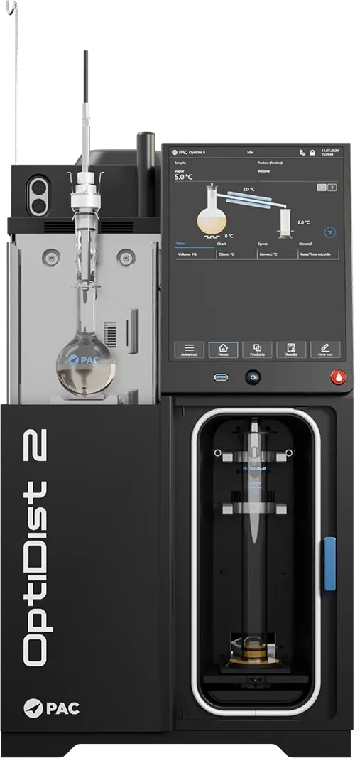
The Next Generation of the Industry-Leading Atmospheric Distillation Benchmark
PAC is proud to introduce the OptiDist 2—the next evolution of the industry-standard atmospheric distillation instrument. Engineered for superior performance, precision, and reliability, it builds on the success of its predecessor, the OptiDist, with a redesigned cooling system and advanced optimization technology. This instrument is designed to deliver exceptional results across all sample types, making it the ideal choice for high-efficiency distillation in your laboratory.
With over 5,000 instruments deployed globally, the OptiDist has long set the standard for precision and reliability in distillation measurement, making it the trusted benchmark in the industry.
The OptiDist 2 is fully compliant with ASTM D86, D1078, D8540, EN ISO3405, ISO 918, IP 123, IP 195, DIN 1751, and JIS standards.
The OptiDist 2 is compatible with both IRIS and PACe for lab monitoring.
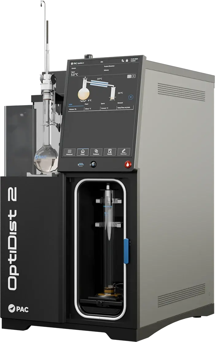
Unmatched Cooling Performance for Consistent, Reliable Results
The OptiDist 2’s groundbreaking thermosyphon cooling system offers exceptional precision and efficiency, ensuring your distillation results are always accurate and reliable. With its sealed, no-moving-parts design, this innovative cooling system guarantees even temperature control across the entire condenser assembly. The efficient fluid flow design reduces maintenance needs, allowing you to focus on productivity without worrying about downtime. This advanced system is the key to the OptiDist 2’s superior repeatability, making it the perfect choice for labs demanding top-tier performance.
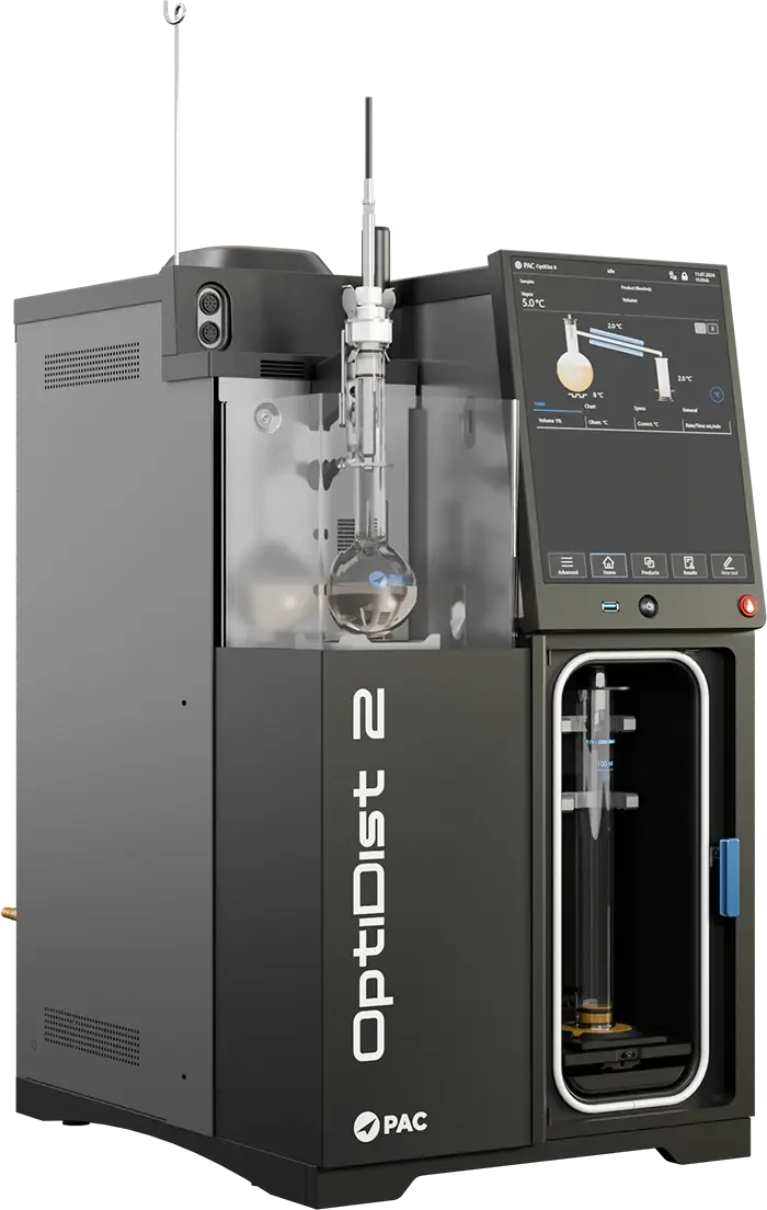
Technology for Effortless Precision
The combination of Peltier elements and a dual-optimizer heater control system in the OptiDist 2 ensures smooth, efficient distillation with minimal user input. The Peltier elements quickly react to changes in distillation conditions, providing an additional layer of temperature regulation for flawless results. Meanwhile, the dual-optimizer heater system continuously monitors both sample and vapor temperatures, maintaining optimal heating levels for precise distillation—even with difficult samples. Together, these technologies deliver exceptional performance, offering you unmatched precision and reliability with every test.
ГОСТ 2177-99 допускает
определение фракционного состава нефти
и нефтепродуктов при помощи автоматического
аппарата [24].
Сущность
метода заключается в перегонке 100 см3
образца в автоматическом аппарате для
перегонки в определенных условиях,
соответствующих его природе и условиям
перегонки при ручном методе (табл. 3.2).
Таблица 3.2
Условия испытаний
|
Наименование показателя |
Значения |
|||
|
1 |
2 |
3 |
4 |
|
|
Характеристика |
||||
|
давление |
65,5 |
<65,5 |
||
|
температура |
– |
100 |
>100 |
|
|
конечная |
250 |
>250 |
||
|
Температурный |
0–300 |
0–400 |
||
|
Условия испытания: |
||||
|
температура |
13–18 |
≤ |
||
|
температура |
13–18 |
От 13 до температуры |
||
|
объем |
125 |
|||
|
Условия проведения |
||||
|
температура |
0–1 |
0–4 |
0–60 |
|
|
температура |
13–18 |
В |
||
|
время |
5–10 |
5–15 |
||
|
время |
60–75 |
– |
||
|
стандарт. |
4–5 |
|||
|
время |
3–5 |
5 |
Аппаратура
[25]
Рис.
3.6. Автоматический анализатор
фракционного состава нефти и нефтепродуктов
при атмосферном
давлении PAC OptiDist [17]
Анализатор фракционного
состава PAC OptiDist
(рис. 3.6) обладает уникальной системой
оптимизации нагрева, что позволяет с
первой попытки проводить анализ в полном
соответствии со стандартом даже для
неизвестных образцов. Оператор освобожден
от подбора оптимальных параметров
эксперимента.
Прибор может
работать как в автономном режиме, так
и в рамках лабораторной сети, передавая
результаты эксперимента на управляющий
компьютер.
Встроенный
микропроцессорный контроль всех блоков
анализатора обеспечивает полную
функциональную диагностику при включении
и по запросу. Управление автономной
работой осуществляется через встроенный
цветной сенсорный монитор.
Прибор оснащен:
-
встроенной
замкнутой герметичной системой
компрессорного охлаждения трубки
конденсатора и приемного отделения с
термостатированием и программированием; -
бустером-нагревателем
для баллистического (практически
мгновенного) разогрева трубки конденсора
при осуществлении разгонки сырой нефти
по ГОСТ 2177 (метод Б); -
встроенным цифровым
барометром для автоматического
приведения результатов к нормальному
давлению, с системой одноточечной
калибровки по текущему давлению; -
защитой от запуска
при отсутствии колбы или цилиндра; -
датчиком температуры
паров со встроенной микросхемой памяти
калибровочных данных; -
оптической системой
детектирования объема.
Таблица 3.3
Техническая
характеристика анализатора фракционного
состава
PAC OptiDist [25]
|
Программируемая |
0–65 |
|
Программируемая |
0–40 |
|
Температурный |
0–450 |
|
Измерение |
0–103 |
|
точность, |
±0,1 |
|
разрешение, |
0,03 |
|
Датчик |
500–800 |
|
Пожаротушение |
2 |
|
Окружающая |
|
|
температура, |
10–35 |
|
относительная |
80 |
|
Электропитание |
100–240 В, 50/60 Гц, 1400 |
Соседние файлы в папке Лаборатория
- #
- #
- #
- #
- #

СТ РК ISO 3405, ГОСТ 2177, ГОСТР ЕН ИСО 3405, ASTM D1078, ASTM D850, ASTM D86, IP 123, IP 195, ISO 3405,СТ РК ИСО 3405
Анализатор OptiDist от компании Herzog – это революционно новый, простой в использовании автоматический анализатор фракционного состава, позволяющий получать высокоточные результаты. Это ультрасовременное решение для проведения анализа фракционного состава при атмосферном давлении. Анализатор OptiDist отличается большой многофункциональностью и легко устанавливается. Аппарат компактен, экономит рабочее место. Анализатор OptiDist используется для проведения атмосферной разгонки нефти, конденсата газового стабильного и нефтепродуктов.
- Таблица
- Преимущества
- Комплектация
| Электропитание | 100-240 В, 1400 Вт |
| Габаритные размеры | 440 х 570 х 650 мм (ШхГхВ) |
| Вес | 68 кг |
- Прибор предназначен для анализа не только светлых нефтепродуктов, но
и для анализа сырой нефти и стабильного газового конденсата в полном со-
ответствии с ГОСТ 2177-99 (А и Б), обеспечивает разгонку до 360°С. - Определение фракционного состава проводится полностью в автомати-
ческом режиме. - Аппарат прост в использовании, запуск анализа производится нажатием
одной кнопки. - Не требуется проведение предварительных тестов или настроек, уникаль-
ная система оптимизации нагрева (Optimizer) позволяет с первой попытки
проводить анализ в полном соответствии со стандартом даже для неизвестных образцов — пропускная спо-
собность прибора возрастает и оператор освобожден от подбора оптимальных параметров эксперимента. - Не требует каких-либо внешних систем охлаждения.
- Управление прибором осуществляется с помощью большого удобного цветного сенсорного дисплея.
- Полностью русифицированное меню.
- Автоматическое опускание малоинерционного нагревательного элемента по завершении анализа, и
включения эффективного вентилятора, что обеспечивает быстрое остывание колбы и готовность при-
бора к следующему анализу. - Встроенный барометр позволяет автоматически проводить коррекцию на текущее атмосферное давление.
- Уникальная система измерения объема отогнанного дистиллята дает точные результаты, даже при
анализе сложных образцов (например сырая нефть с присадками), при анализе которых выделяется
большое количество дыма. - Автоматическое выполнение анализа включает в себя: контроль температуры нагревателя, времени
до начала кипения, температуры первой капли (начало кипения), скорости разгонки, температуры па-
ров, температуры конца кипения по падению температуры паров или датчику последней капли. - Инновационная система обеспечивает сверхстабильную скорость разгонки и исключает возможность
«заплескивания» при анализе сложных образцов. - Аппарат имеет улучшенные характеристики безопасности, а именно: прибор оснащен системой автомати-
ческого пожаротушения с двумя многоразовыми датчиками открытого пламени, что позволяет исключить
не только первичные, но и вторичные очаги возгорания, в том числе внизу нагревательного отделения.
- Автоматический аппарат OptiDist
- Датчик температуры паров, калиброванный, с чипом
- Приемный цилиндр 100 мл на латунной подставке
- Колба для разгонки 125 мл
- Пробка термометра под колбы
- Пластина нагревателя 38 мм
- Пластина нагревателя 50 мм
- Резиновая крышка мерного цилиндра
- Шомпол очистки трубки конденсора
- Кипелки
- Жидкость термостата, 1 л
- ГСО фракционного состава
- Бумага для принтера
Скачать каталог
Наши проекты
Полезное
Отзывы
Опрос
-
Нравится 11 (69%) Воздержусь 4 (25%) Не нравится 1 (6%)