
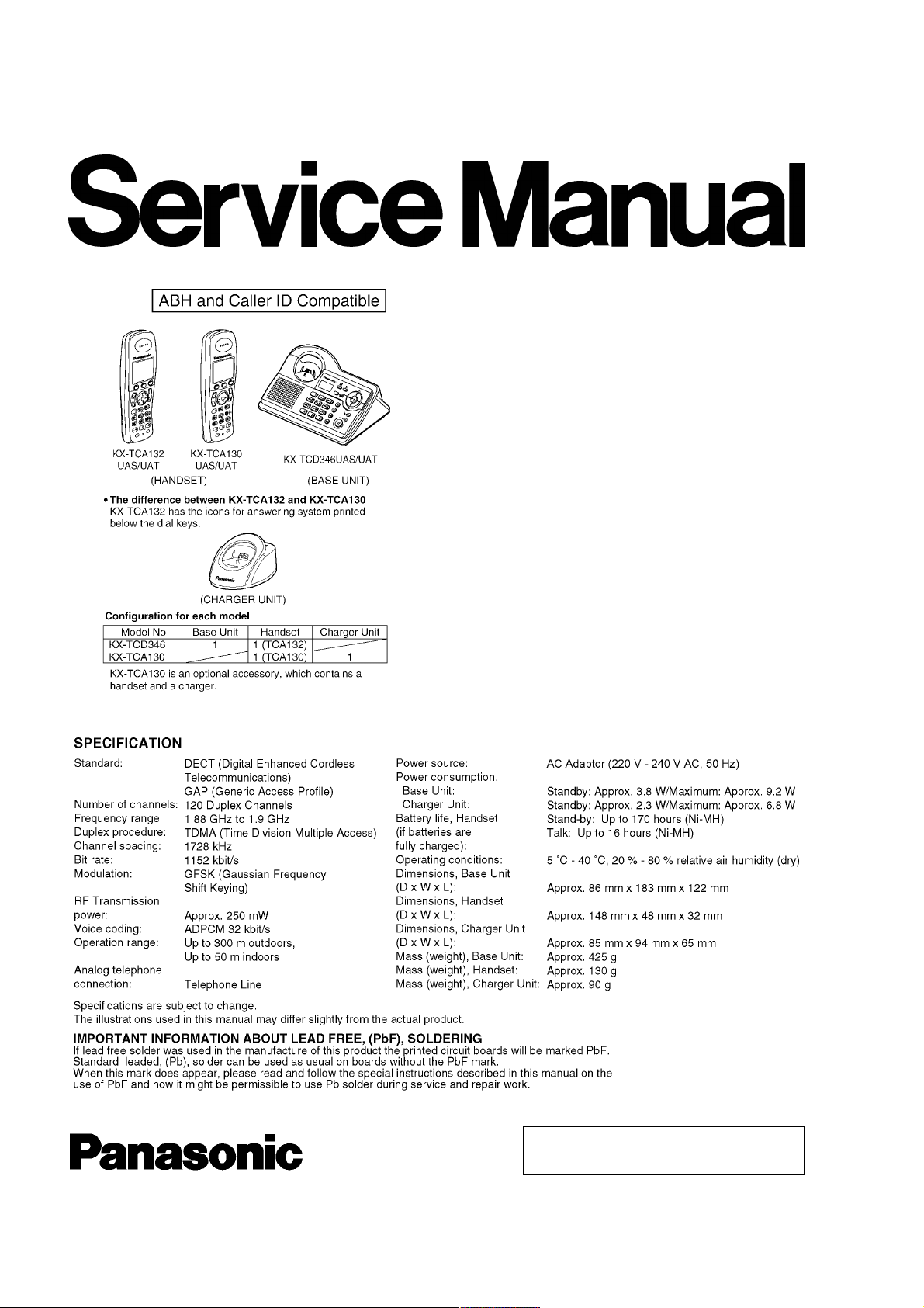
ORDER NO. KM40507827CE
Telephone Equipment
KX-TCD346UAS
KX-TCD346UAT
KX-TCA132UAS
KX-TCA132UAT
KX-TCA130UAS
KX-TCA130UAT
Digital Cordless Answering System
Silver Version
Titanium Black Version
(for Ukraine)
© 2005 Panasonic Communi cations Co., Ltd. All
rights reserved. Unauthorized copying and
distribution is a violation of law.
KX-TCD346UAS / KX-TCD346 UAT / KX-TCA132UAS / KX-TCA132UAT / KX-TCA130 UAS / KX- TCA130UAT
Note:
Because CONTENTS 4 is the extract from the Operating Instructions of this model, it is subject to change without notice. You can
download and refer to the original Operating Instructions on TSN Server for further information.
CONTENTS
Page Page
1 ABOUT LEAD FREE SOLDER (PbF: Pb free) 4
1.1. Suggested PbF Solder
1.2. How to recognize that Pb Free solder is used
2 FOR SERVICE TECHNICIANS
3 CAUTION
4 OPERATING INSTRUCTIONS
4.1. Battery
4.2. Location of Controls
4.3. Connections
4.4. Guide to Settings
4.5. For Service Hint
5 DISASSEMBLY INSTRUCTIONS
5.1. Base Unit
5.2. Handset
5.3. Charger Unit
6 ASSEMBLY INSTRUCTIONS
6.1. Fix the LCD to the Main P.C.Board (Handset)
7 TROUBLESHOOTIN G FLOWCHART
7.1. Check Power
7.2. Check Battery Charge
7.3. Check Link
7.4. Check Handset Transmission
7.5. Check Handset Reception
7.6. Check Caller ID
7.7. Check Base Speakerphone Transmiss ion
7.8. Check Base Speakerphone Reception
7.9. Bell Reception
7.10. Check TAM Operation
8 TROUBLESHOOTIN G BY SYMPTOM (BASE UNIT AND
CHARGER UNIT)
8.1. Check Point (Base Unit)
8.2. The Setting Method of JIG (Base Unit)
8.3. Adjustment Standard (Base Unit)
8.4. Check Point (Charger Unit)
8.5. Adjustment Standard (Charger Unit)
9 TROUBLESHOOTIN G BY SYMPTOM (HANDSET)
9.1. Check Point (Handset)
11
12
13
14
14
15
16
17
17
18
19
20
21
25
25
25
25
25
26
26
27
27
32
33
34
34
35
35
4
5
6
6
7
7
9
9.2. Troubleshooting for Speakerp hone (Handset)
9.3. The Setting Method of JIG (Handset)
9.4. Adjustment Standard (Handset)
10 THINGS TO DO AFTER REPLACING IC
10.1. Base Unit
10.2. Handset
11 RF SPECIFICATION
11.1. Base Unit
11.2. Handset
12 HOW TO CHECK THE SPEAKER OR RECEIVER
13 FREQUENCY TABLE (MHz)
14 BLOCK DIAGRAM (BASE UNIT)
15 CIRCUIT OPERATION (BASE UNIT)
15.1. Outline
15.2. Power Supply Circuit
15.3. Telephone Line Interface
15.4. Transmitter/Receiver
15.5. Pulse Dialling
16 BLOCK DIAGRAM (HANDSET)
17 CIRCUIT OPERATION (HANDSET)
17.1. Outline
17.2. Power Supply Circuit/Reset Circuit
17.3. Charge Circuit
17.4. Battery Low/Power Down Detector
17.5. Speakerphone
18 CIRCUIT OPERATION (CHARGER UNIT)
18.1. Power Supply Circuit
19 SIGNAL ROUTE
20 CPU DATA (BASE UNIT)
20.1. IC4 (BBIC)
21 CPU DATA (HANDSET)
21.1. IC1 (BBIC)
22 ENGINEERING MODE
22.1. Base Unit
22.2. Handset
23 EEPROM LAYOUT (BASE UNIT)
23.1. Scope
38
39
40
41
41
41
42
42
42
43
43
44
45
45
46
47
47
47
48
49
49
49
49
49
49
50
50
51
53
53
56
56
58
58
61
63
63
2
KX-TCD346UAS / KX-TCD346 UAT / KX-TCA132UAS / KX-TCA132UAT / KX-TCA130 UAS / KX- TCA130UAT
23.2. Introduction 63
23.3. EEPROM Layout
24 EEPROM LAYOUT (HANDSET)
24.1. Scope
24.2. Introduction
24.3. EEPROM contents
25 HOW TO REPLACE THE FLAT PACKAGE IC
25.1. PREPARATION
25.2. FLAT PACKAGE IC REMOVA L PROCEDURE
25.3. FLAT PACKAGE IC INSTALLA TION PROCEDURE
25.4. BRIDGE MODIFICATION PROCEDURE
26 CABINET AND ELECTRICAL PARTS (BASE UNIT)
27 CABINET AND ELECTRICAL PARTS (HANDSET)
28 CABINET AND ELECTRICAL PARTS (CHARGER UNIT)
29 ACCESSORIES AND PACKING MATERIALS
29.1. KX-TCD346UAS/UA T
29.2. KX-TCA130UAS/UA T
30 TERMINAL GUIDE OF THE ICs, TRANSISTORS AND DIODES
30.1. Base Unit
30.2. Handset
30.3. Charger Unit
31 REPLACEMENT PARTS LIST
31.1. Base Unit
31.2. Handset
31.3. Charger Unit
63
68
68
68
68
71
71
71
72
72
73
74
75
76
76
77
31.4. Accessories and Packing Materials
31.5. Fixtures and Tools
32 FOR SCHEMATIC DIAGRAM
32.1. Base Unit (SCHEMATIC DIAGRAM (BASE UNIT_MAIN))
32.2. Handset (SCHEMATIC DIAGRAM (HANDSET))
32.3. Charger Unit (SCHEMATIC DIAGRAM (CHARGER UNIT))
33 SCHEMATIC DIAGRAM (BASE UNIT_MAIN)
34 SCHEMATIC DIAGRAM (BASE UNIT_OPERATION)
35 SCHEMATIC DIAGRAM (HANDSET)
36 SCHEMATIC DIAGRAM (CHARGER UNIT)
37 CIRCUIT BOARD (BASE UNIT_MAIN)
37.1. Component View
37.2. Flow Solder Side View
38 CIRCUIT BOARD (BASE UNIT_OPERATION)
38.1. Component View
78
78
78
79
80
80
83
38.2. Flow Solder Side View
39 CIRCUIT BOARD (HANDSET)
39.1. Component View
39.2. Flow Solder Side View
40 CIRCUIT BOARD (CHARGER UNIT)
40.1. Component View
40.2. Flow Solder Side View
84
85
85
87
87
87
87
88
90
92
94
95
95
96
97
97
98
99
99
100
101
101
101
3
KX-TCD346UAS / KX-TCD346 UAT / KX-TCA132UAS / KX-TCA132UAT / KX-TCA130 UAS / KX- TCA130UAT
1 ABOUT LEAD FREE SOLDER (PbF: Pb free)
Note:
In the information below, Pb, the symbol for lead in the periodic table of elements, will refer to standard solder or solder that
contains lead.
We will use PbF solder when discussing the lead free solder used in our manufacturing process which is made from Tin (Sn),
Silver (Ag), and Copper (Cu).
This model, and others like it, manufactured using lead free solder will have PbF stamped on the PCB. For service and repair
work we suggest using the same type of solder although, with some precautions, standard Pb solder can also be used.
Caution
· PbF solder has a melting point that is 50°F ~ 70°F (30°C ~ 40°C) higher than Pb solder. Please use a soldering iron with
temperature control and adjust it to 700°F ± 20°F (370°C ± 10°C). In case of using high temperature soldering iron, please
be careful not to heat too long.
· PbF solder will tend to splash if it is heated much higher than its melting point, approximately 1100°F (600°C).
· If you must use Pb solder on a PCB manufactured using PbF solder, remove as much of the original PbF solder as possible
and be sure that any remaining is melted prior to applying the Pb solder.
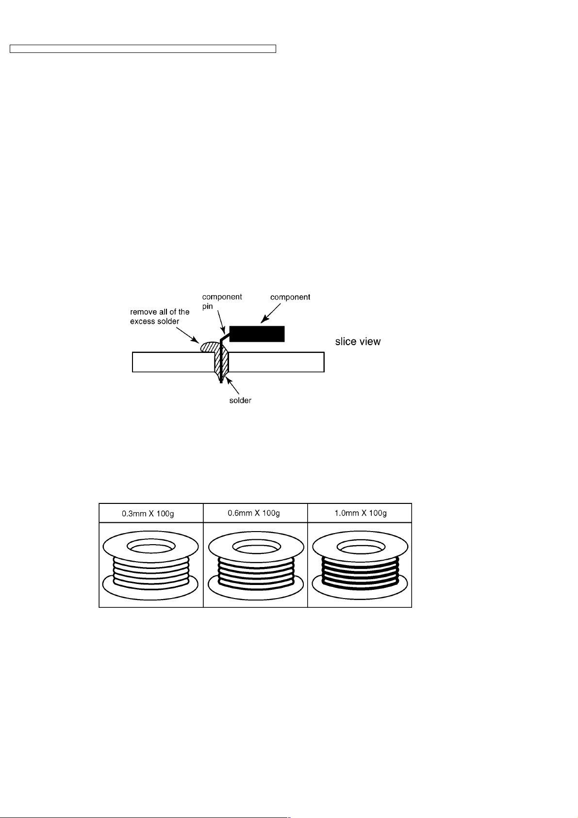
· W hen applying PbF solder to double layered boards, please check the component side for excess which may flow onto the
opposite side (See the figure below).
1.1. Suggested PbF Solder
There are several types of PbF solder available commercially. While this product is manufactured using Tin, Silver, and Copper
(Sn+Ag+Cu), you can also use Tin and Copper (Sn+Cu) or Tin, Zinc, and Bismuth (Sn+Zn+Bi). Please check the
manufacturer’s specific instructions for the melting points of their products and any precautions for using their product with other
materials.
The following lead free (PbF) solder wire sizes are recommended for service of this product: 0.3mm, 0.6mm and 1.0mm.
4
KX-TCD346UAS / KX-TCD346 UAT / KX-TCA132UAS / KX-TCA132UAT / KX-TCA130 UAS / KX- TCA130UAT
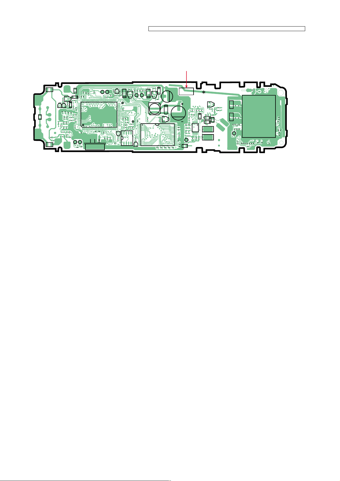
1.2. How to recognize that Pb Free solder is used
(Example: Handset P.C.B.)
Marked
GND
C18
J1
L4
J3
C71
R38
J4
C74
C73
L5
F1
C128
C127
D7
R5
Q4
102
R7
D6
103
Q5
Q9
R72
R6
C23
C90
C89
C37
C91
C68
C10
R29
R26
C8
C12 C14
C87
R25
R37
R95
C17
128
1
C22
C39
R46
R47
C137
R43
UTX
URX
J2
R21
R20
BAT
C9
R24
R73
IC1
C58
C24
R19
X1
R137
R136
R81
Q19
C40
C109
R3
R2
C21
C20
C7
VDDE
65
TP12
64
C19
C93
C94
R63
39
R64
38
Q18
R15
IC10
C6
C56
R11
R10C4R12
R4
Q2
TP16
TP11
R9
C5
Q3
L1
JTAG
C140
R61
R39
R57
R60 1 48
R40
R59
Q17
C134
(Component View)
Note:
The location of the “PbF” mark is subject to change without notice.
R82
IC11
R1
C133
C3
D9
PbF
PQUP11277Z
A201
C125
C1
C115
C116
R135
R134
REV_TEST2
REV_TEST1
C114
C120
C121
C119
R122
R121
C45
R127
C117
R128
CLK
R125
R126
CN6
C44
R124
R123
R130
C46
C47
C54
C55
C48C49
R129
C53
C83
R75
R132
R131
C51
C126
C50
A
C132
Q16
C92
C16
C15
D1
C57
Q1
C131
C130
C129
C135
C136
C139
C138
C102
C76
C38
L6
C86
C30
R80
R35
C75
C77
R36
R74
TP10
R117
C84
D8
C79
D5
D4
SP_TEST1
SP_TEST2
C85
C95
C13
IC2
C80
C78
5

KX-TCD346UAS / KX-TCD346 UAT / KX-TCA132UAS / KX-TCA132UAT / KX-TCA130 UAS / KX- TCA130UAT
2 FOR SERVICE TECHNICIANS
ICs and LSIs are vulnerable to static electricity.
When repairing, the following precautions will help prevent recurring malfunctions.
1. Cover the plastic parts boxes with aluminum foil and ground them.
2. Ground the soldering irons.
3. Use a conductive mat on the worktable.
4. Do not touch IC or LSI pins with bare fingers.
3 CAUTION
Danger of explosion if battery is incorrectly replaced. Replace only with the same or equivalent type recommended by the
manufacturer.
Dispose of used batteries according to the manufacture’s Instructions.
6
KX-TCD346UAS / KX-TCD346 UAT / KX-TCA132UAS / KX-TCA132UAT / KX-TCA130 UAS / KX- TCA130UAT
4 OPERATING INSTRUCTIONS
4.1. Battery
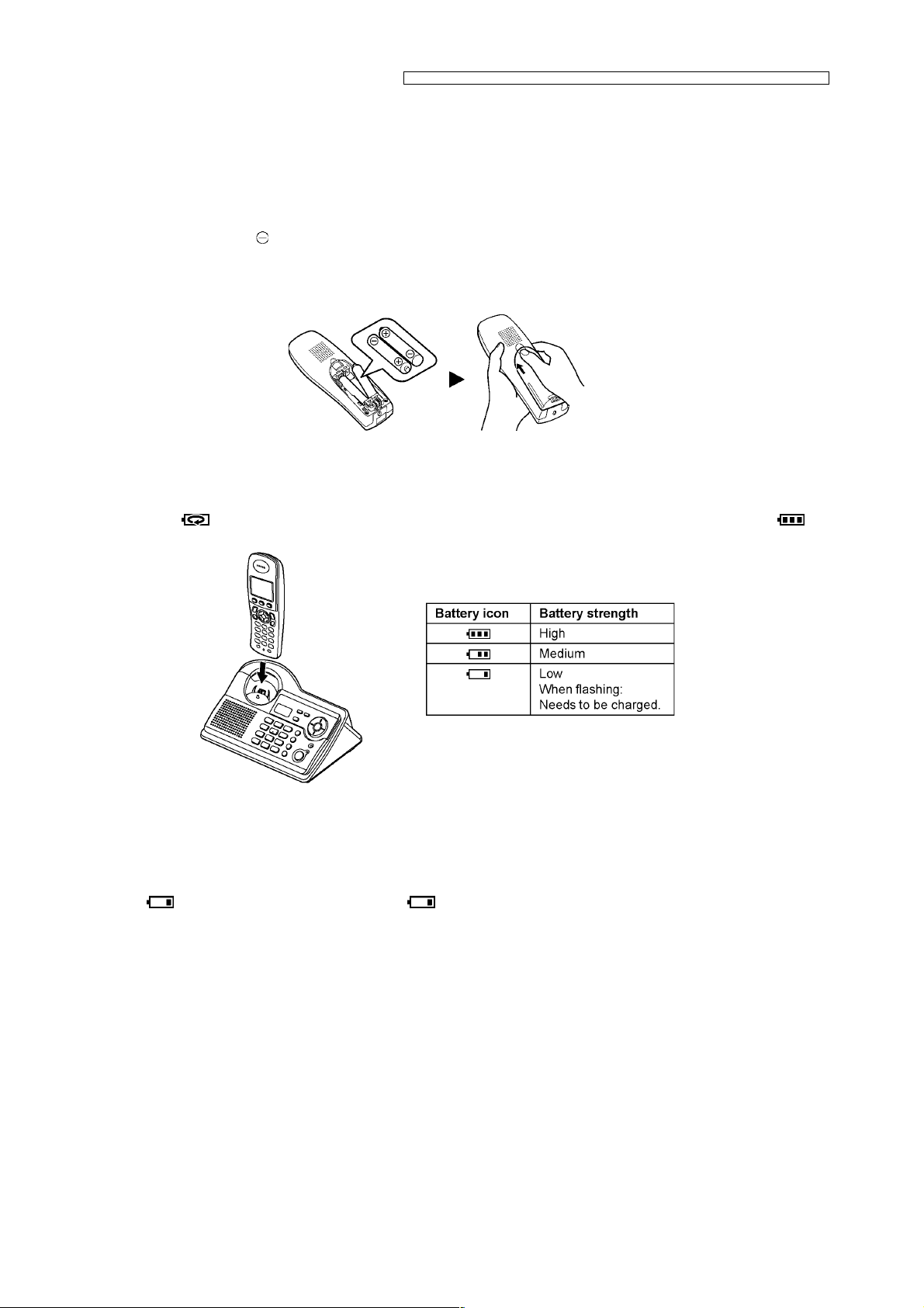
4.1.1. Battery Installation
1. Insert the batteries negative ( ) terminal first.
2. Close the handset cover.
Note:
· Use only rechargeable Ni-MH batteries P03P (HHR-4EPT).
4.1.2. Battery Charge
Place the handset on the base unit for about 7 hours before initial use.
When charging,
remains on the display.
and battery strength icon are alternately shown on the display. When the batteries are fully charged,
Note:
· It is normal for the handset to feel warm during charging.
· It takes 7 hours to fully charge the batteries, however, you can use the handset before the batteries are fully charged.
· Clean the charge contacts of the handset and base unit with a soft, dry cloth, otherwise the batteries may not charge
properly. Clean if the unit is exposed to grease, dust or high humidity.
· W hen
least 15 minutes.
· If the handset is turned off, it will be turned on automatically when it is placed on the base unit.
flashes, recharge the handset batteries. will continue to flash until the batteries have been charged for at
7
KX-TCD346UAS / KX-TCD346 UAT / KX-TCA132UAS / KX-TCA132UAT / KX-TCA130 UAS / KX- TCA130UAT
4.1.3. Battery Life
After your Panasonic batteries are fully charged, you can expect the following performance:
Ni-MH batteries (700 mAh)
Operation Operating Time
While in use (talking) 16 hours max.
While not in use (standby) 170 hours max.
Note:
· Actual battery performance depends on a combination of how often the handset is in use (talking) and how often it is not
in use (standby).
· Battery operating time may be shortened over time depending on usage conditions and ambient temperature.
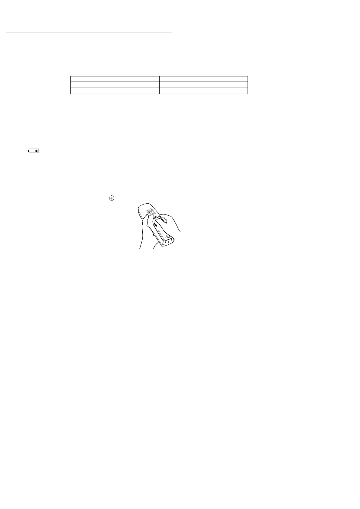
4.1.4. Battery Replacement
If flashes even after the handset batteries have been charged for 7 hours, the batteries must be replaced.
Important:
· W e recommend the use of Panasonic rechargeable Ni-MH batteries P03P (HHR-4EPT). If you install non-rechargeable
batteries and start charging, the batteries may leak electrolyte.
· Do not mix old and new batteries.
1. Press the notch on the handset cover firmly and slide it in the direction of the arrow.
2. Remove the old batteries positive (
) terminal first and install the new ones.
8
4.2. Location of Controls
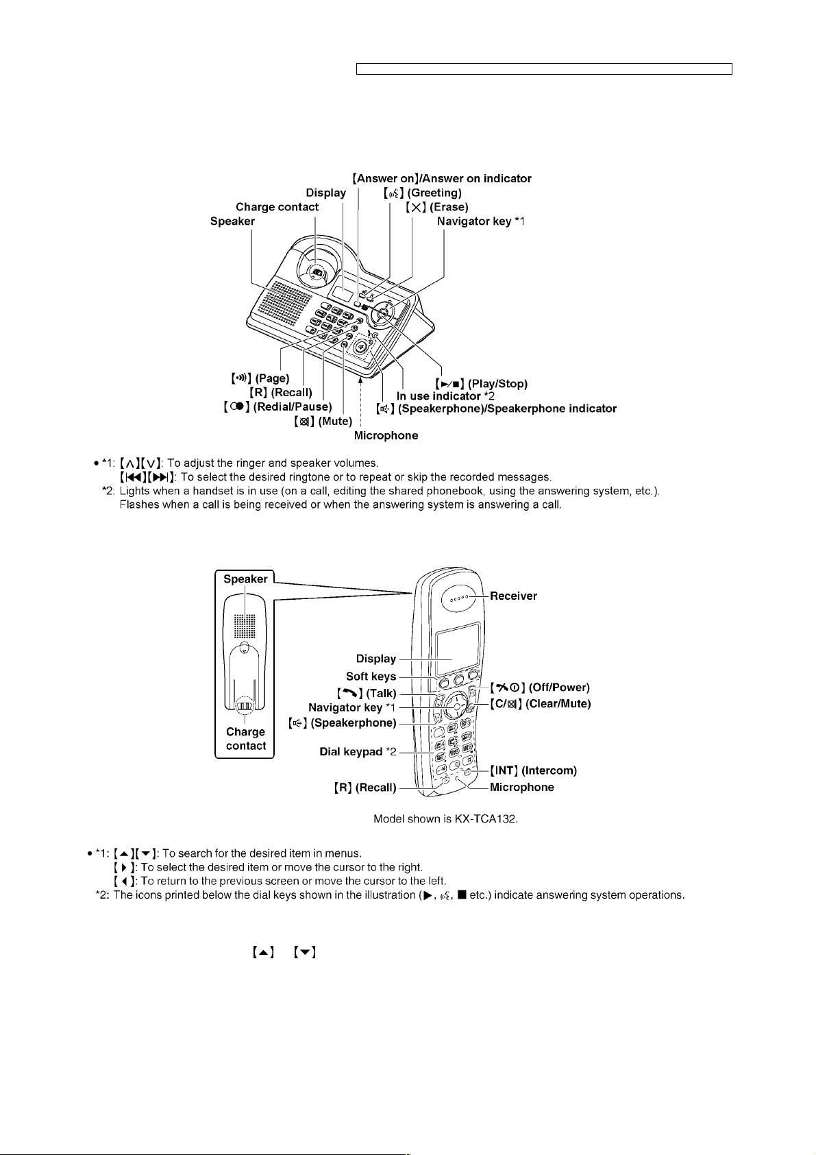
4.2.1. Base Unit
KX-TCD346UAS / KX-TCD346 UAT / KX-TCA132UAS / KX-TCA132UAT / KX-TCA130 UAS / KX- TCA130UAT
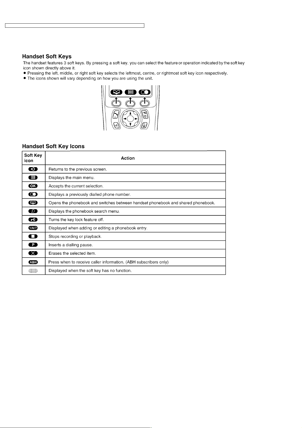
4.2.2. Handset
Note:
· Up to 3 menu items can be displayed at a time. To select a menu item not shown on the current page, scroll up or down
by pressing the navigator key,
or , respectively.
9
KX-TCD346UAS / KX-TCD346 UAT / KX-TCA132UAS / KX-TCA132UAT / KX-TCA130 UAS / KX- TCA130UAT
10
KX-TCD346UAS / KX-TCD346 UAT / KX-TCA132UAS / KX-TCA132UAT / KX-TCA130 UAS / KX- TCA130UAT
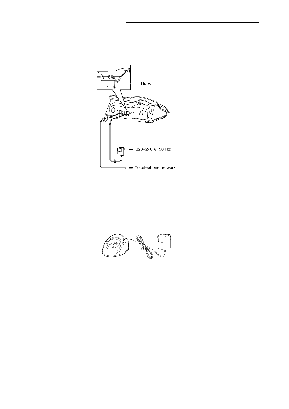
4.3. Connections
4.3.1. Base Unit
When the AC adaptor is connected, a short beep will be heard. If it is not heard, check the connections.
Important:
· Use only the AC adaptor PQLV19CEX and telephone line cord supplied with this unit.
Note:
· After connection, you must charge the batteries to make or answer calls with the handset.
· Never install telephone wiring during a lightning storm.
· The AC adaptor must remain connected at all times. (It is normal for the adaptor to feel warm during use.)
· The AC adaptor should be connected to a vertically oriented or floor-mounted AC outlet. Do not connect the AC adaptor to
a ceiling-mounted AC outlet, as the weight of the adaptor may cause it to become disconnected.
4.3.2. Charger Unit
Important:
· Use only the AC adaptor PQLV200CEX.
Note:
· The AC adaptor must remain connected at all times (It is normal for the adaptor to feel warm during use).
11
KX-TCD346UAS / KX-TCD346 UAT / KX-TCA132UAS / KX-TCA132UAT / KX-TCA130 UAS / KX- TCA130UAT
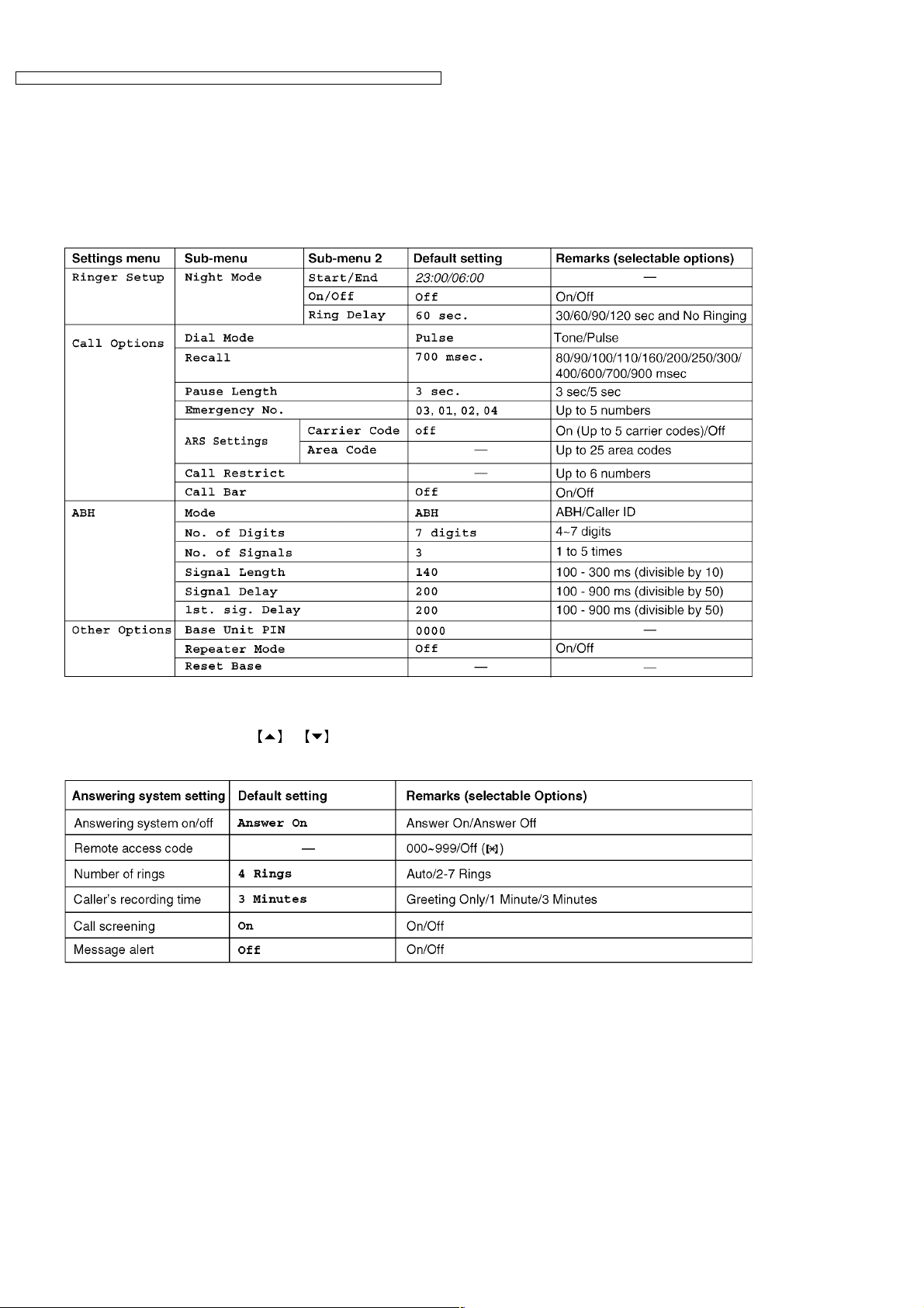
4.4. Guide to Settings
For your reference, a chart of all items which can be customised for the base unit and the handset is printed below.
· W hen customising the base unit and the handset, the current item or setting is highlighted.
4.4.1. Base Unit Settings
· These items are customised using the handset.
Note:
· Up to 3 menu items can be displayed at a time. To select a menu item not shown on the current page, scroll up or down
by pressing the navigator key,
or , respectively.
4.4.2. Answering System Settings
12
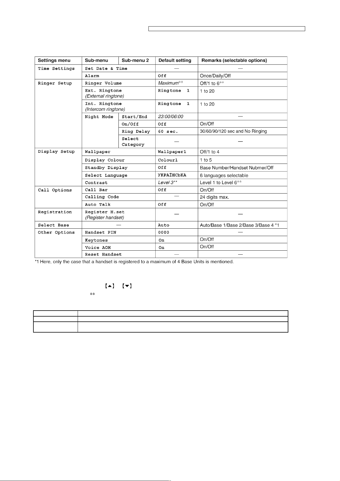
4.4.3. Handset Settings
KX-TCD346UAS / KX-TCD346 UAT / KX-TCA132UAS / KX-TCA132UAT / KX-TCA130 UAS / KX- TCA130UAT
Note:
· Up to 3 menu items can be displayed at a time. To select a menu item not shown on the current page, scroll up or down
by pressing the navigator key,
· The items with a mark “
” are not shown on the display.
or , respectively.
4.5. For Service Hint
Items Contents
Battery You could use other rechargeable batteries sold in a market, but the unit is not guaranteed to work properly.
PIN Code If you forget Base Unit or Handset PIN code, press *, 7, 0, 0, 0 as a PIN code. This is called “super password”
and is effective when you have forgotten the PIN code.
13
KX-TCD346UAS / KX-TCD346 UAT / KX-TCA132UAS / KX-TCA132UAT / KX-TCA130 UAS / KX- TCA130UAT
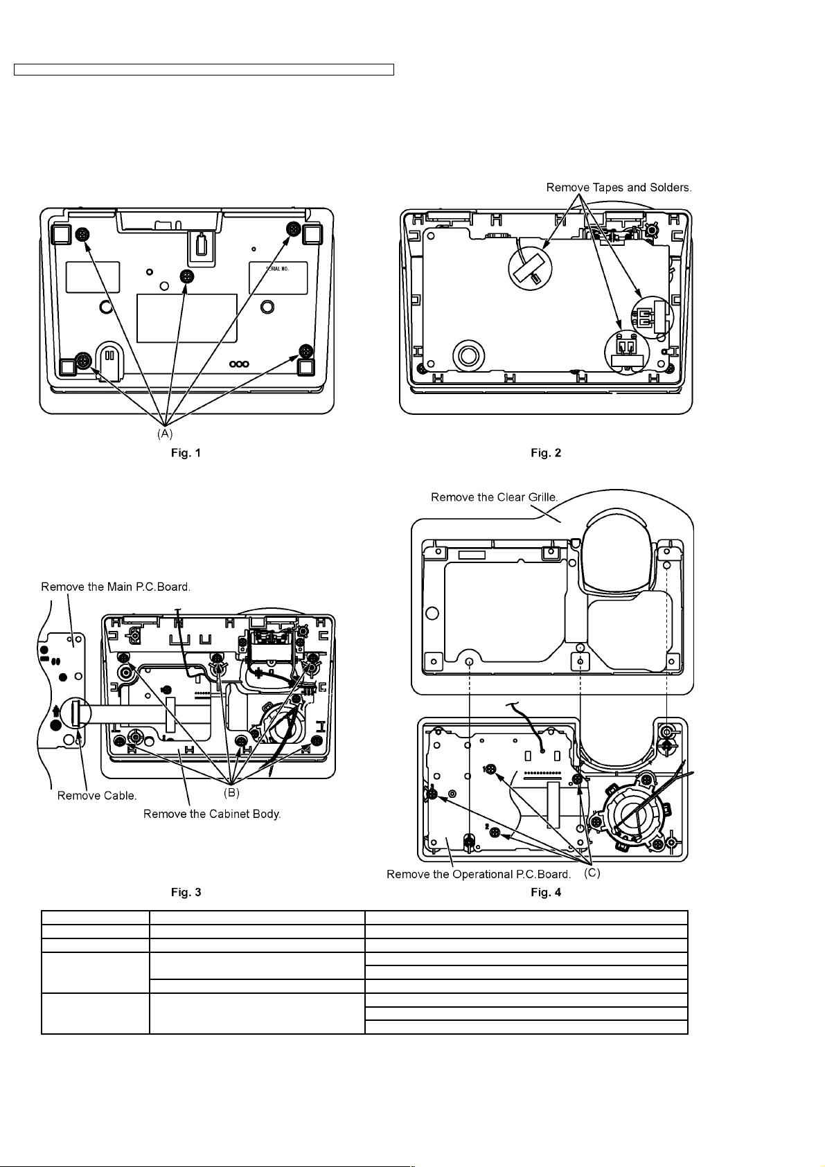
5 DISASSEMBLY INSTRUCTIONS
5.1. Base Unit
Shown in Fig.- To Remove Remove
1 Cabinet Cover Screws (2.6 × 14)……..(A) × 5
2 Main P.C.Board Tapes and Solders
3 Main P.C.Board Cable
Cabinet Body Screws (2.6 × 14)……….(B) × 6
4 Operational P.C.Board Clear Grille
Main P.C.Board
Screws (2.6 × 8)………….(C) × 4
Operational P.C.Board
14
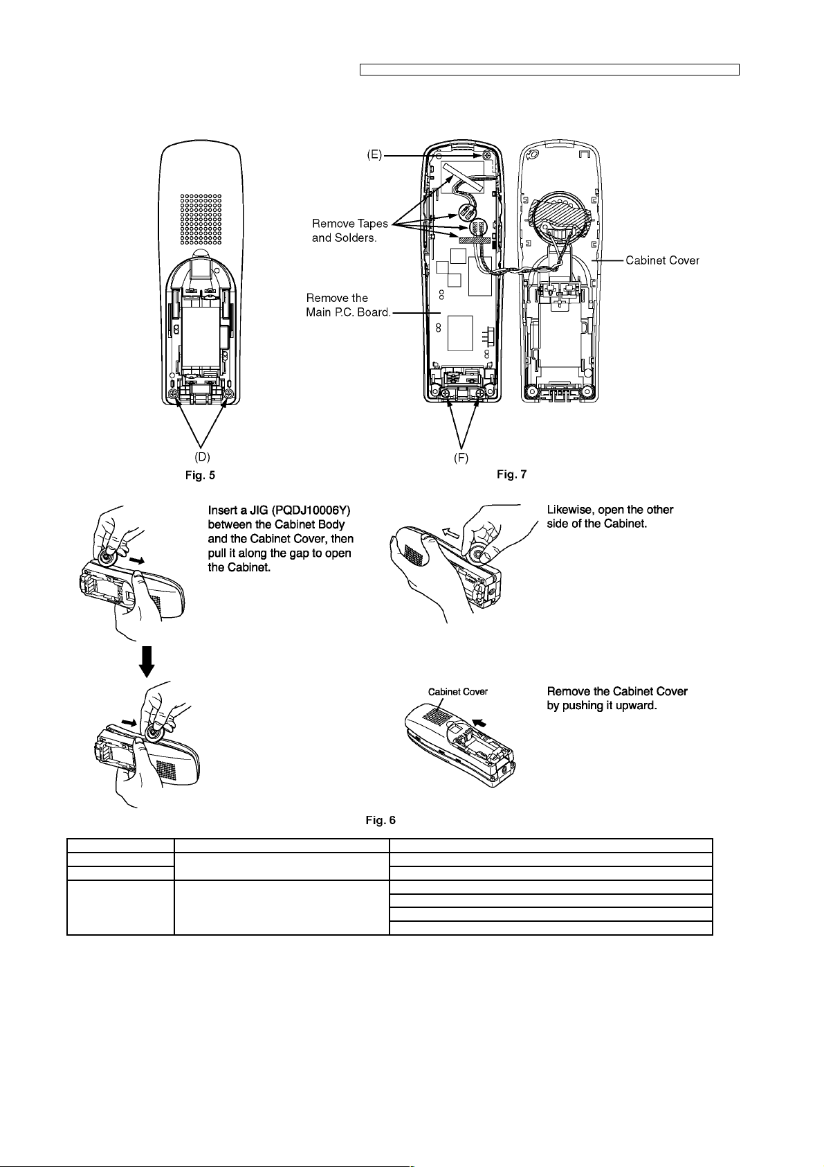
5.2. Handset
KX-TCD346UAS / KX-TCD346 UAT / KX-TCA132UAS / KX-TCA132UAT / KX-TCA130 UAS / KX- TCA130UAT
Shown in Fig.- To Remove Remove
5 Cabinet Cover Screws (2 × 10)……….(D) × 2
6 Follow the procedure.
7 Main P.C.Board Screw (2 × 10)…………(E) × 1
Screws (2 × 10)……….(F) × 2
Tapes and Solders
Main P.C.Board
15
KX-TCD346UAS / KX-TCD346 UAT / KX-TCA132UAS / KX-TCA132UAT / KX-TCA130 UAS / KX- TCA130UAT
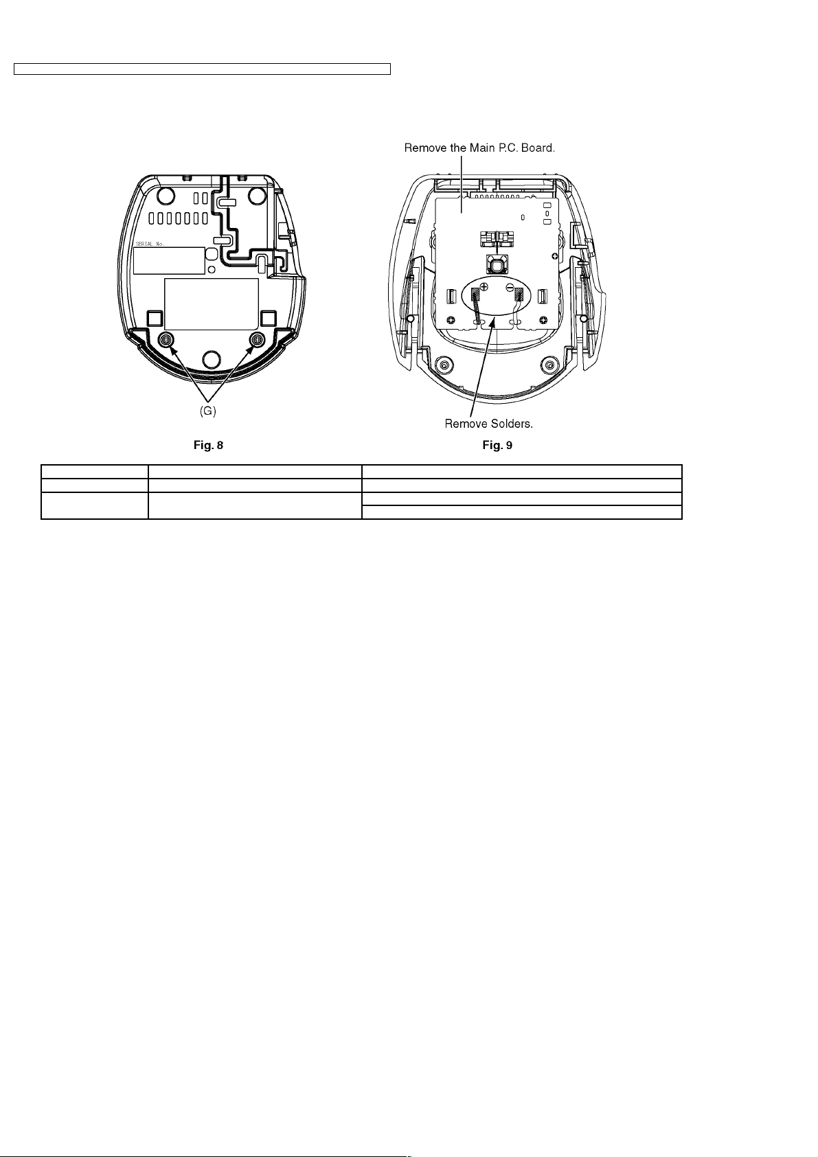
5.3. Charger Unit
Shown in Fig.- To Remove Remove
8 Cabinet Cover Screws (2.6 × 10)……….(G) × 2
9 Main P.C.Board Solders
Main P.C.Board
16
KX-TCD346UAS / KX-TCD346 UAT / KX-TCA132UAS / KX-TCA132UAT / KX-TCA130 UAS / KX- TCA130UAT
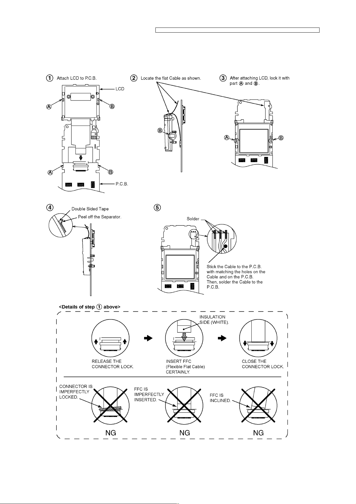
6 ASSEMBLY INSTRUCTIONS
6.1. Fix the LCD to the Main P.C.Board (Handset)
17
KX-TCD346UAS / KX-TCD346 UAT / KX-TCA132UAS / KX-TCA132UAT / KX-TCA130 UAS / KX- TCA130UAT
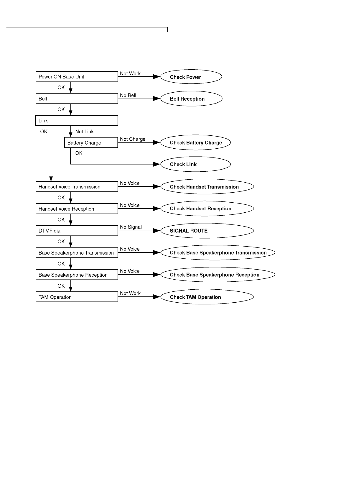
7 TROUBLESHOOTING FLOWCHART
Flow Chart
Cross Reference:
Check Power (P.19)
Bell Reception (P.26)
Check Battery Charge (P.20)
Check Link (P.21)
Check Handset Transmission (P.25)
Check Handset Reception (P.25)
SIGNAL ROUTE (P.51)
Check Base Speakerphone Transmission (P.25)
Check Base Speakerphone Reception (P.25)
Check TAM Operation (P.26)
18
KX-TCD346UAS / KX-TCD346 UAT / KX-TCA132UAS / KX-TCA132UAT / KX-TCA130 UAS / KX- TCA130UAT
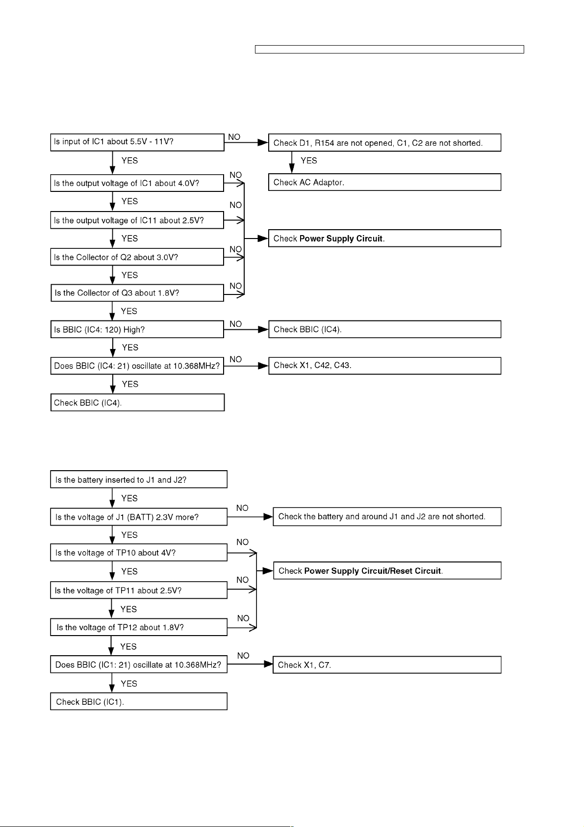
7.1. Check Power
7.1.1. Base Unit
Is the AC Adaptor inserted into AC outlet? (Check AC Adaptor’s specification.)
Cross Reference:
Power Supply Circuit (P.46)
7.1.2. Handset
Cross Reference:
Power Supply Circuit/Reset Circuit (P.49)
19
KX-TCD346UAS / KX-TCD346 UAT / KX-TCA132UAS / KX-TCA132UAT / KX-TCA130 UAS / KX- TCA130UAT
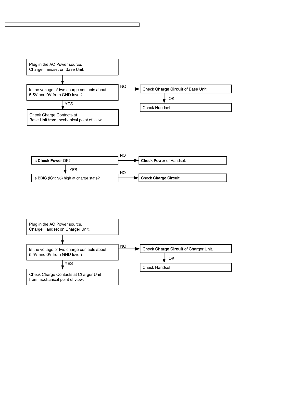
7.2. Check Battery Charge
7.2.1. Base Unit
Cross Reference:
Charge Circuit (P.49)
7.2.2. Handset
Cross Reference:
Check Power (P.19)
Charge Circuit (P.49)
7.2.3. Charger Unit
Cross Reference:
Charge Circuit (P.49)
20
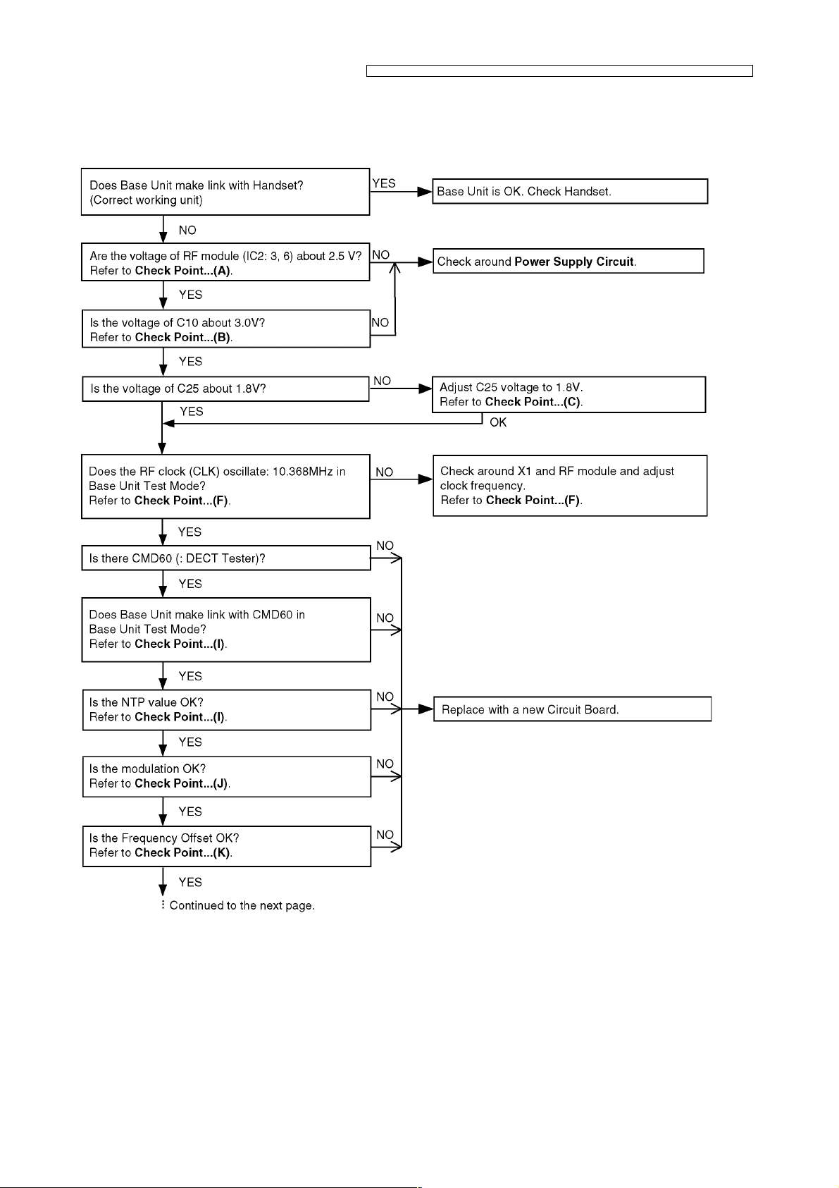
7.3. Check Link
7.3.1. Base Unit
KX-TCD346UAS / KX-TCD346 UAT / KX-TCA132UAS / KX-TCA132UAT / KX-TCA130 UAS / KX- TCA130UAT
21
KX-TCD346UAS / KX-TCD346 UAT / KX-TCA132UAS / KX-TCA132UAT / KX-TCA130 UAS / KX- TCA130UAT
Cross Reference:
Power Supply Circuit (P.46)
Check Point (Base Unit) (P.27)
22
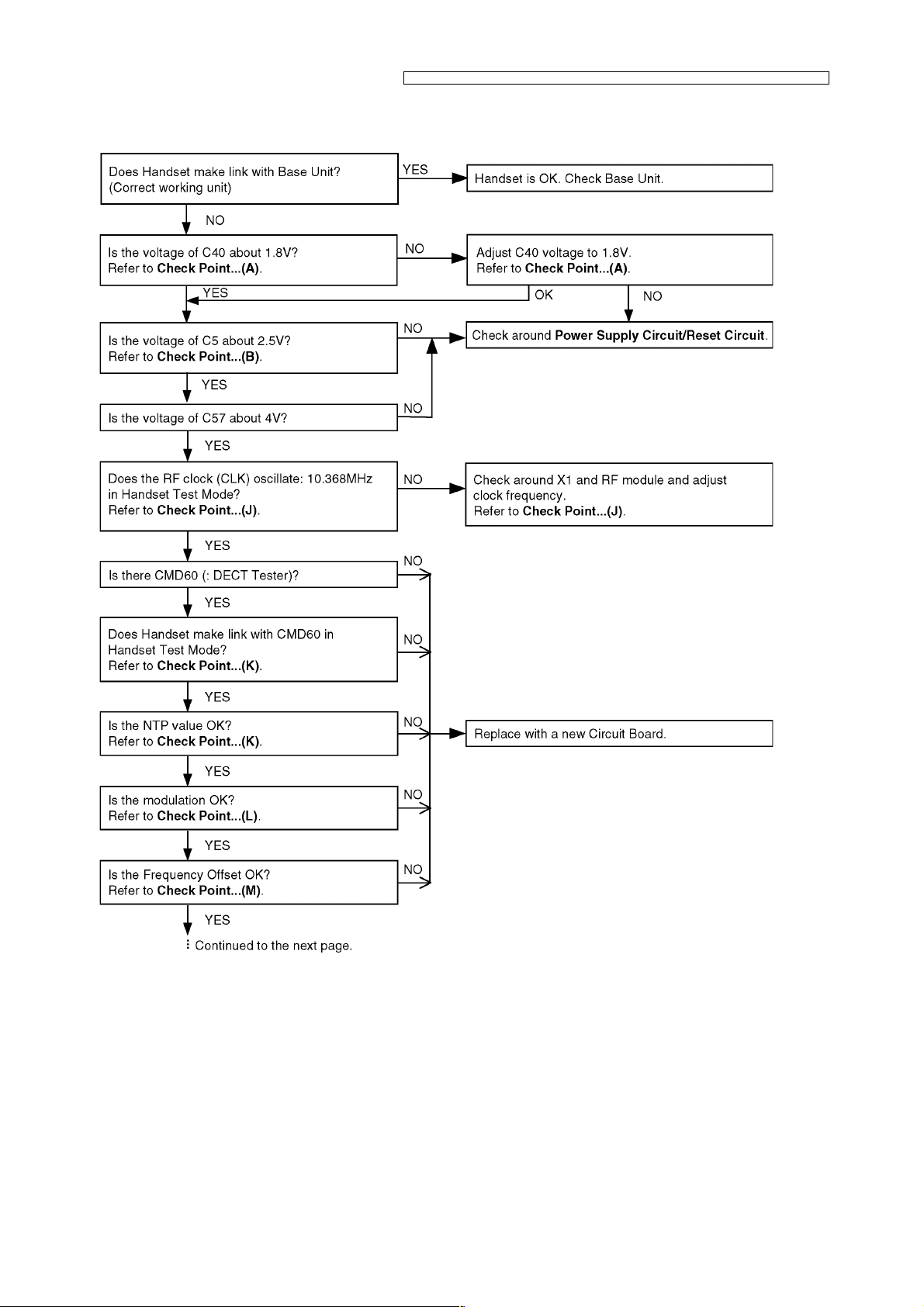
7.3.2. Handset
KX-TCD346UAS / KX-TCD346 UAT / KX-TCA132UAS / KX-TCA132UAT / KX-TCA130 UAS / KX- TCA130UAT
23
KX-TCD346UAS / KX-TCD346 UAT / KX-TCA132UAS / KX-TCA132UAT / KX-TCA130 UAS / KX- TCA130UAT
Cross Reference:
Power Supply Circuit/Reset Circuit (P.49)
Check Point (Handset) (P.35)
24
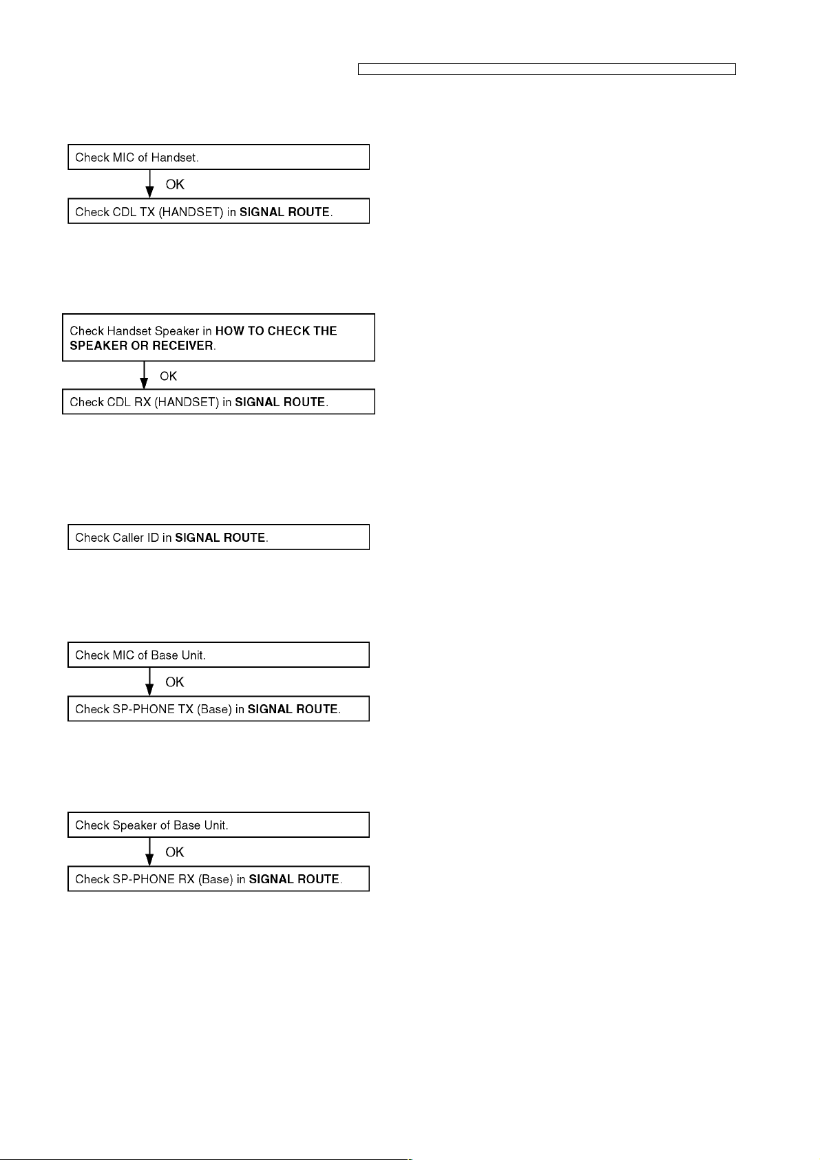
7.4. Check Handset Transmission
Cross Reference:
SIGNAL ROUTE (P.51)
7.5. Check Handset Reception
Cross Reference:
HOW TO CHECK THE SPEAKER OR RECEIVER (P.43).
SIGNAL ROUTE (P.51)
KX-TCD346UAS / KX-TCD346 UAT / KX-TCA132UAS / KX-TCA132UAT / KX-TCA130 UAS / KX- TCA130UAT
7.6. Check Caller ID
Cross Reference:
SIGNAL ROUTE (P.51)
7.7. Check Base Speakerphone Transmission
Cross Reference:
SIGNAL ROUTE (P.51)
7.8. Check Base Speakerphone Reception
Cross Reference:
SIGNAL ROUTE (P.51)
25
KX-TCD346UAS / KX-TCD346 UAT / KX-TCA132UAS / KX-TCA132UAT / KX-TCA130 UAS / KX- TCA130UAT
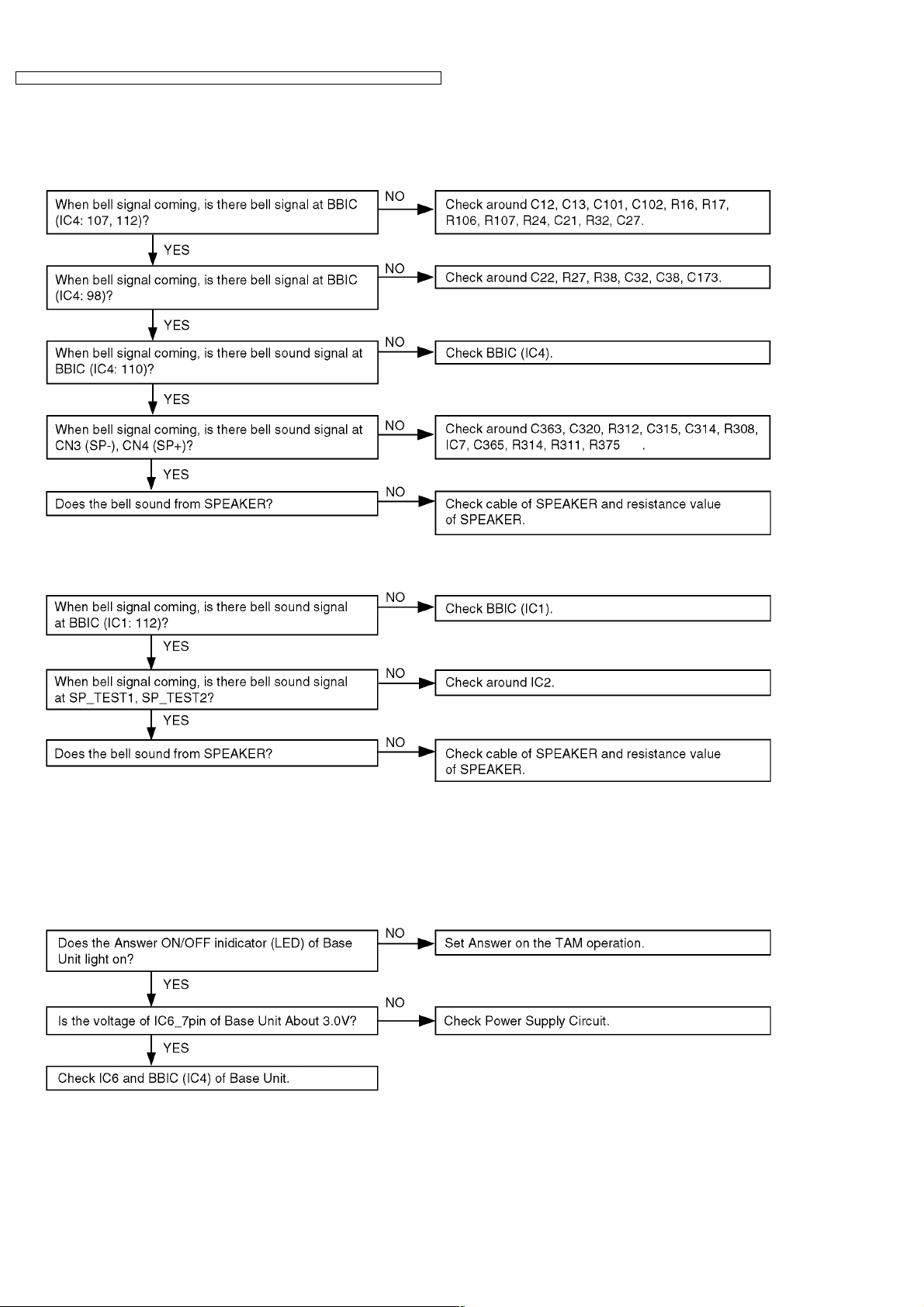
7.9. Bell Reception
7.9.1. Base Unit
7.9.2. Handset
Cross Reference:
Telephone Line Interface (P.47)
Check Link (P.21)
HOW TO CHECK THE SPEAKER OR RECEIVER (P.43)
7.10. Check TAM Operation
Cross Reference:
Power Supply Circuit (P.46)
26
KX-TCD346UAS / KX-TCD346 UAT / KX-TCA132UAS / KX-TCA132UAT / KX-TCA130 UAS / KX- TCA130UAT
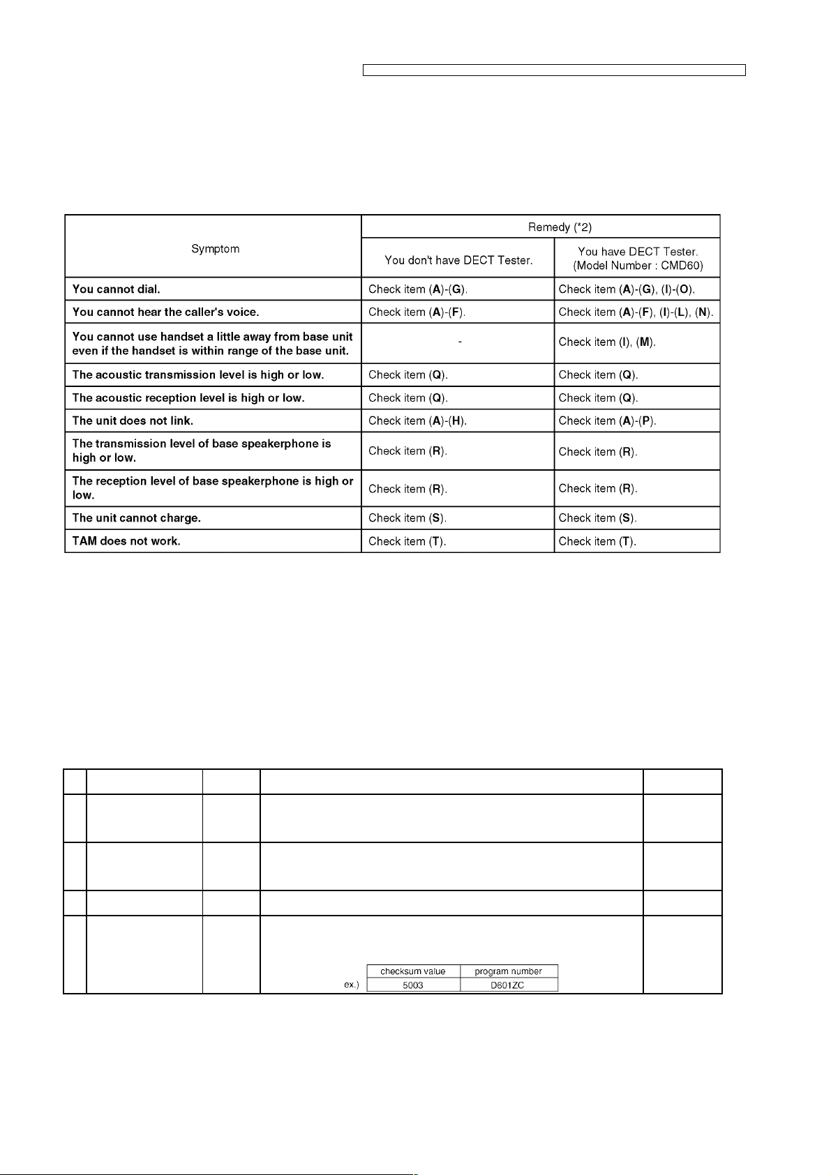
8 TROUBLESHOOTING BY SYMPTOM (BASE UNIT AND
CHARGER UNIT)
If your unit has below symptoms, follow the instructions in remedy column. Remedies depend on whether you have DECT tester
(*1) or not.
Note:
(*1): A general repair is possible even if you don’t have the DECT tester because it is for confirming the levels, such as Acoustic
level in detail.
(*2): Refer to Check Point (Base Unit) (P.27)
8.1. Check Point (Base Unit)
Please follow the items below when BBIC or EEPROM or FLASH ROM is replaced.
Note:
After the measuring, sock up the solder of TP.
*: PC Setting (P.39) is required beforehand.
The connections of adjustment equipments are as shown in Adjustment Standard (Base Unit) (P.33).
Items Check
(A) 2.5V Supply
Confirmation
(B) 3.0V Supply
Confirmation
(C)* 1.8V Supply
Confirmation
(D)* BBIC Confirmation — 1. BBIC Confirmation (Execute the command «getchk»).
Point
VDD4 1. Confirm that the voltage between test point VDD4 and GND is 2.5V ± 0.2V. D1, IC11, C4,
VDD3 1. Confirm that the voltage between test point VDD3 and GND is 3.0V ± 0.2V. C2, IC1, C3,
VDD5 1. Confirm that the voltage between test point VDD5 and GND is 1.8V ± 0.1V. Q3, R6, C25,
2. Confirm the returned checksum value.
Connection of checksum value and program number is shown below.
Procedure Check or
Replace Parts
C7, R10, R11,
C30, C26, C28,
L12
C8, Q2, R5,
C10, R18, R19,
C11
D7, D8
IC4, X1, C42,
C43, R40, C81,
C82, C84
27
KX-TCD346UAS / KX-TCD346 UAT / KX-TCA132UAS / KX-TCA132UAT / KX-TCA130 UAS / KX- TCA130UAT
Items Check
Point
(E)* EEP-ROM Confirmation — 1. EEP-ROM Confirmation (Execute the command «ChkTCD240XXrevYY»).
XX: country code
YY: revision number
2. Confirm the returned checksum value.
Procedure Check or
Note:
“XX”, “YY”, and “checksum ” vary depending on the country version. You can
(F)* BBIC Clock Adjustmen t CLK 1. Input Command “rdeeprom 00 01 01”, then you can confirm the current value.
(G)* Hookswitch Check with
DC Characteristics
(H)* DTMF Generator Check — 1. Connect CN1 (Telephone Socket) to DTMF tester.
(I)* Transmitted Power
Confirmation
(J) Modulation Check and
Adjustment
— 1. Connect CN1 (Telephone Socket) to Tel-simulator which is connected with
— Remove L4 before starting step from 1 to 7.
— Follow steps 1 to 6 of (I).
find them in the batch file, PQZZ- mentioned in JIG and PC (P.32).
2. Adjust the frequency of CLK executing the command “setfreq xx (where xx is
the value)” so that the reading of the frequency counter is 10.368000MHz ±
10Hz.
600 Ω .
2. Set line voltage to 48V and line current to 40mA at off-hook condition of
nomal telephone.
3. Execute the command “hookoff”
4. Confirm that the line current is 40mA ± 5mA.
5. Execute the command “hookon”.
6. Confirm that the line current is less than + 0.8mA.
2. Execute the command “hookoff” and “dtmf_hi”.
3. Confirm that the high frequency (1477Hz) is -3 ± 2dBm.
4. Execute the command “dtmf_lo”.
5. Confirm that the low frequency (852Hz) is -6 ± 2dBm.
1. Configure the DECT tester (CMD60) as follows;
<Setting>
· Test mode: FP
· Traffic Carrier: 5
· Traffic Slot: 4
· Mode: Loopback
· PMID: 00000
· RF LEVEL = -70dBm.
2. Execute the command “testmode”.
3. Execute the command “sendchar dmv 2 2”.
4. Check that “Signalling Status” has been set to “Locked“, then press “ACCEPT
RFPI“.
5. Initiate connectio n from Dect tester (“set up connect”)
6. Execute the command “ANT1”.
7. Confirm that the NTP value at ANT is 20dBm ~ 25dBm.
7.Confirm that the B-Field Modulation is -350 ~ -400/+320 ~ +370kHz/div
using data type Fig31.
8.Adjust the B-Field Modulation if required. (Execute the command “readmod”
and “wrtmod xx”, where xx is the value.)
Replace Parts
IC3, C53, R56,
R57, C57, Q6,
Q7, R64, R65,
R35
IC2, IC4, R137,
R125, C153,
X1, C42, C43
CN1, L6, L7,
Q4, R23, R25,
Q5, R26, R28,
IC4, D3
IC4, R63, R39,
C41, R49, C46,
C47, R42, R43,
R44, R45, R46,
R47, R48,
C108, C109,
C40, C36, Q8,
D4
IC2, IC4, R137,
R125, C153, L8,
L5, L10, L9,
C140, C141,
DA1, C142,
C143, C144, L3,
L4, R118, R119,
L12, C30, IC11,
R10, R11, C28,
C26, C147,
C151, C157,
R123, C158,
R128, R129,
C159, C160,
R131, R130,
C161, C162,
R132, C164,
C136, R134,
R117, R127,
C156, C154,
C155, R135,
R136
IC2, IC4, R137,
R125, C153, L8,
L5, L10, L9,
C140, C141,
DA1, C142,
C143, C144, L3,
L4, R118, R119,
L12, C30, IC11,
R10, R11, C28,
C26, C147,
C151, C157,
R123, C158,
R128, R129,
C159, C160,
R131, R130,
C161, C162,
R132, C164,
C136, R134,
R117, R127,
C156, C154,
C155, R135,
R136
28
KX-TCD346UAS / KX-TCD346 UAT / KX-TCA132UAS / KX-TCA132UAT / KX-TCA130 UAS / KX- TCA130UAT
Items Check
Point
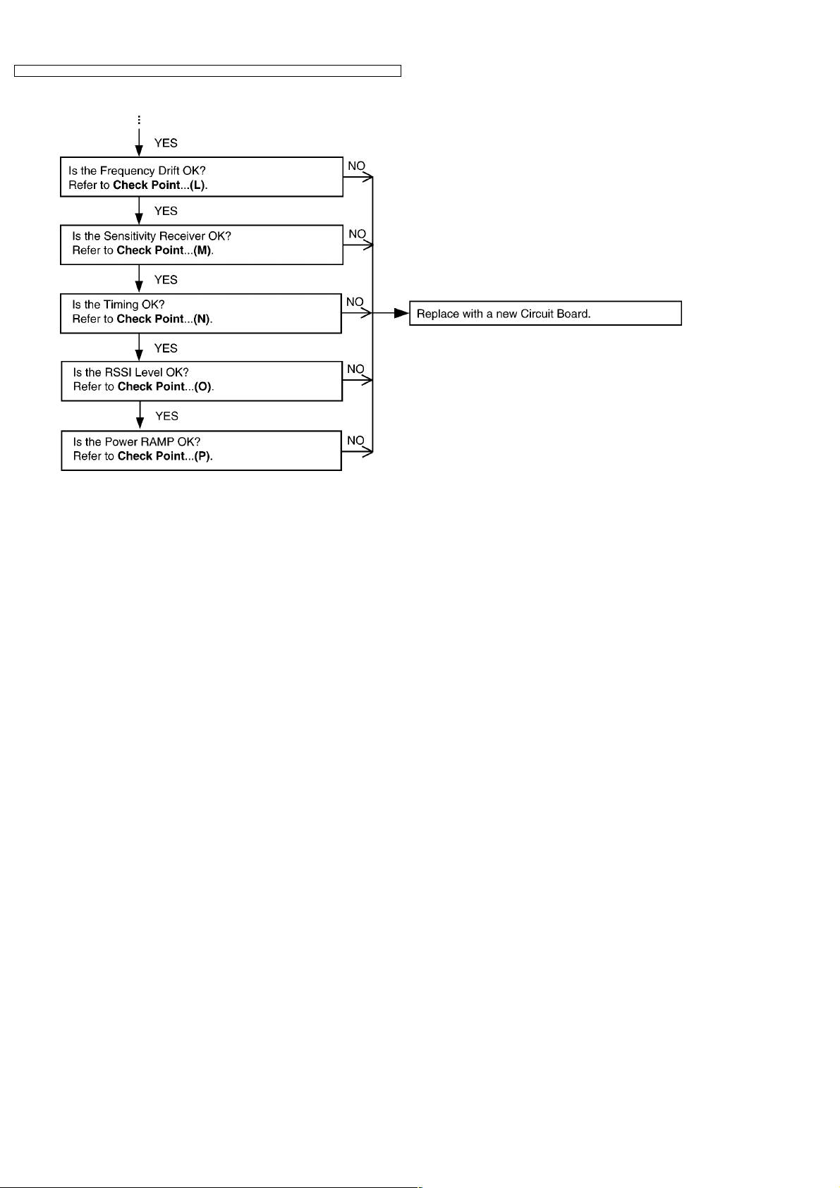
(K) Frequency Offset Check — Follow steps 1 to 6 of (I).
7.Confirm that the frequency offset is < ± 45kHz.
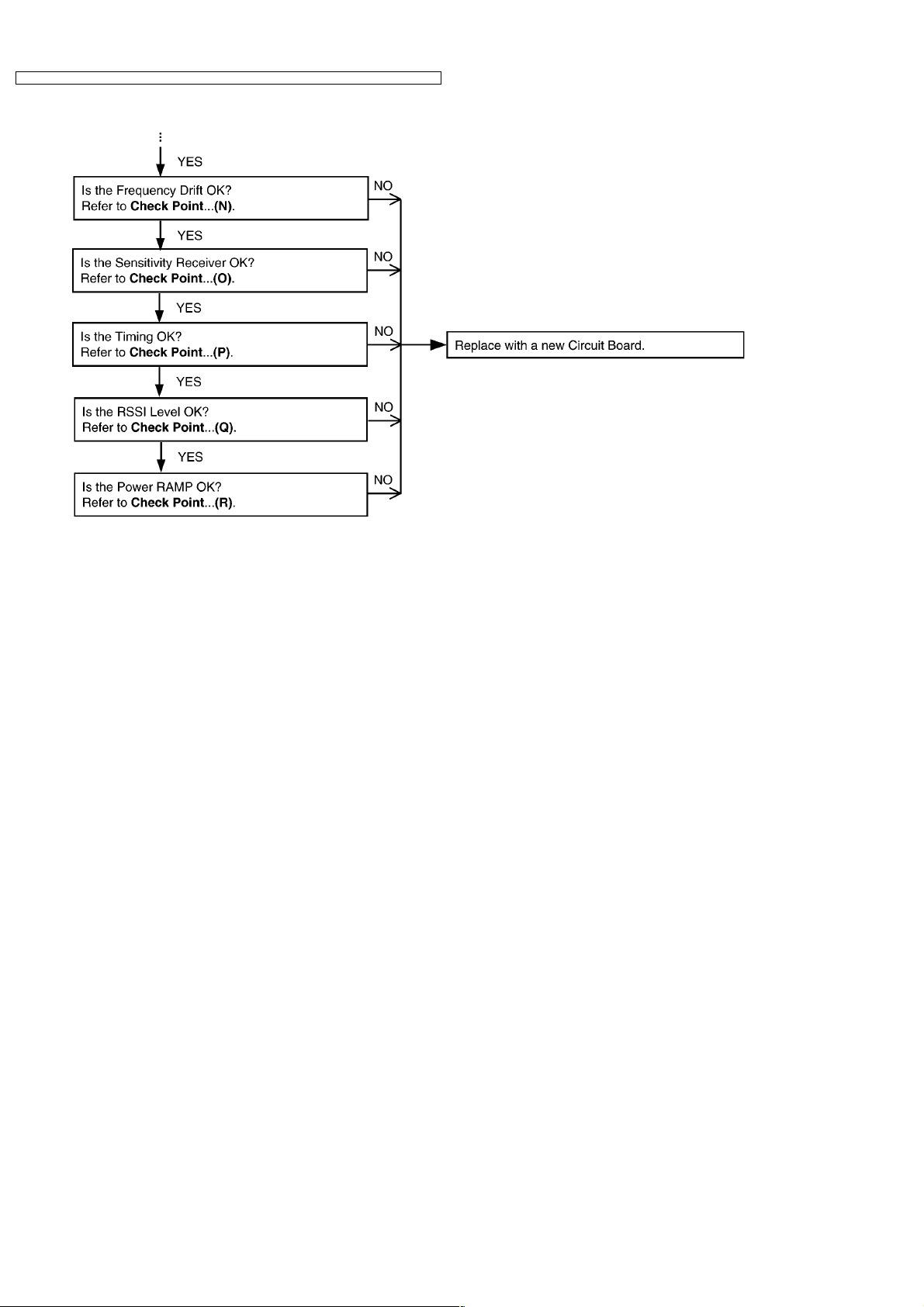
(L) Frequency Dirft
Confirmation
(M) Sensitivity Receiver
Confirmation
— Follow steps 1 to 6 of (I).
7.Confirm that the frequency drift is < ± 30kHz/ms.
— Follow steps 1 to 6 of (I).
7.Set DECT tester power to -88dBm.
8.Confirm that the BER is < 1000ppm.
Procedure Check or
Replace Parts
IC2, IC4, R137,
R125, C153, L8,
L5, L10, L9,
C140, C141,
DA1, C142,
C143, C144, L3,
L4, R118, R119,
L12, C30, IC11,
R10, R11, C28,
C26, C147,
C151, C157,
R123, C158,
R128, R129,
C159, C160,
R131, R130,
C161, C162,
R132, C164,
C136, R134,
R117, R127,
C156, C154,
C155, R135,
R136
IC2, IC4, R137,
R125, C153, L8,
L5, L10, L9,
C140, C141,
DA1, C142,
C143, C144, L3,
L4, R118, R119,
L12, C30, IC11,
R10, R11, C28,
C26, C147,
C151, C157,
R123, C158,
R128, R129,
C159, C160,
R131, R130,
C161, C162,
R132, C164,
C136, R134,
R117, R127,
C156, C154,
C155, R135,
R136
IC2, IC4, R137,
R125, C153, L8,
L5, L10, L9,
C140, C141,
DA1, C142,
C143, C144, L3,
L4, R118, R119,
L12, C30, IC11,
R10, R11, C28,
C26, C147,
C151, C157,
R123, C158,
R128, R129,
C159, C160,
R131, R130,
C161, C162,
R132, C164,
C136, R134,
R117, R127,
C156, C154,
C155, R135,
R136
29
KX-TCD346UAS / KX-TCD346 UAT / KX-TCA132UAS / KX-TCA132UAT / KX-TCA130 UAS / KX- TCA130UAT
Items Check
Point
(N) Timing Confirmation — Follow steps 1 to 6 of (I).
7.Confirm that the Timing accuracy is < ± 2.0ppm.
(O)* RSSI Level
Confirmation
— Follow steps 1 to 6 of (I).
7.Execute the command «readrssi» .
8. Confirm that the returned value is 0×22 ± A (hex).
(P) Power RAMP
Confirmation
— Follow steps 1 to 6 of (I).
7.Confirm that Power RAMP is matching.
Procedure Check or
Replace Parts
IC2, IC4, R137,
R125, C153, L8,
L5, L10, L9,
C140, C141,
DA1, C142,
C143, C144, L3,
L4, R118, R119,
L12, C30, IC11,
R10, R11, C28,
C26, C147,
C151, C157,
R123, C158,
R128, R129,
C159, C160,
R131, R130,
C161, C162,
R132, C164,
C136, R134,
R117, R127,
C156, C154,
C155, R135,
R136
IC2, IC4, R137,
R125, C153, L8,
L5, L10, L9,
C140, C141,
DA1, C142,
C143, C144, L3,
L4, R118, R119,
L12, C30, IC11,
R10, R11, C28,
C26, C147,
C151, C157,
R123, C158,
R128, R129,
C159, C160,
R131, R130,
C161, C162,
R132, C164,
C136, R134,
R117, R127,
C156, C154,
C155, R135,
R136
IC2, IC4, R137,
R125, C153, L8,
L5, L10, L9,
C140, C141,
DA1, C142,
C143, C144, L3,
L4, R118, R119,
L12, C30, IC11,
R10, R11, C28,
C26, C147,
C151, C157,
R123, C158,
R128, R129,
C159, C160,
R131, R130,
C161, C162,
R132, C164,
C136, R134,
R117, R127,
C156, C154,
C155, R135,
R136
30
Loading…
Руководства Panasonic KX-TCA132RU Размер файлов: 3272 KB, Язык: English, Формат: pdf, Платформа: Windows/Linux, Дата: 2016-12-23
На данной странице вы можете скачать руководства Panasonic KX-TCA132RU. Мы предлагаем вам ознакомиться с руководством пользователя, инструкцией по сервисному обслуживанию и ремонту.
Также здесь вы найдете список заказных номеров на комплектующие Panasonic KX-TCA132RU.
Все файлы предоставляются исключительно в ознакомительных целях. И не являютя руководством по ремонту, а направлены лишь на то чтобы помочь вам более детально ознакомиться с принципом построения устройства.
Содержимое представленных здесь руководств требуют от вас знания технического английского языка.
Если вы собираетесь скачать руководство по сервисному обслуживанию Panasonic KX-TCA132RU, иными словами сервис мануал, вы дожны обладать хотя бы минимальными познаниями в области электроники и пониманием базовых принципов работы электромеханических устройств.
Для просмотра руководств вам понадобится Adobe Acrobat Reader версии 9 и выше либо другая программа для просмотра pdf файлов.
В связи с популярностью информации представленной на сайте и ее бесплатного предоставления конечному пользователю, убедительная просьба использовать специальные программные продукты для многопотокового скачивания файлов.
Руководства для Panasonic KX-TCA132RU
- Руководство пользователя (User manual)
- Руководство по сервисному обслуживанию (Service manual)
- Руководство по ремонту (Repair manual)
- Перечень комплектующих (PartList)
Инструкция радиотелефона Panasonic KX-TCA132RUS Размер: 1369 KB, Язык: Английский, Расширение: .pdf, Платформа: Adobe Acrobat, Дата: 2017-08-06
Руководство пользователя содержит основные технические характеристики устройства.
Комплект поставки может отличаться от описанного в руководстве.
Отдельная глава руководства пользователя посвящена условиям эксплуатации устройства. Описаны всевозможные варианты монтажа и установки.
Подробно описаны функции и особенности органов управления устройством.
Инструкция Panasonic KX-TCA132RUS предназначена для технически образованных людей и при детальном изучении гарантирует безопасную и долговременную работу устройства.
Руководство пользователя радиотелефона Panasonic KX-TCA132RUS содержит описание процедуры первоначальной настройки и подключения устройства и выполнение процедур сервисного обслуживания и подготовки расходных материалов.
Для изучения файла вам необходимо обладать хотя бы минимальным знанием английского языка, так как инструкция на русском для радиотелефона Panasonic KX-TCA132RUS пока еще не выпущена.
Описание специальных функций описано в отдельной главе инструкции.
Последняя глава руководства по эксплуатации содержит описание основных неисправностей радиотелефона и перечень основных действий по их устранению.
Пожалуйста используйте специальное программное обеспечение для скачивания файлов и по возможности дождитесь окончания загрузки первого файла перед началом загрузки второго.
Перечень основных разделов руководства пользователя радиотелефона Panasonic KX-TCA132RUS
- Технические характеристики
- Варианты монтажа
- Безопасность
- Органы управления
- Настройка устройства
- Стандартные функции
- Основные неисправности радиотелефона Panasonic KX-TCA132RUS
PANASONIC KX-TCA130 TCA132 TCD345 RUS RUT SM
Type: (PDF)
Size
2.0 MB
Page
101
Category
TELEPHONE
SERVICE MANUAL
If you get stuck in repairing a defective appliance
download
this repair information for help. See below.
Good luck to the repair!
Please do not offer the downloaded file for sell only
use it for personal usage!
Looking for similar panasonic manual?
Document preview [1st page]

Click on the link for free download!
Document preview [2nd page]

Click on the link for free download!
Please tick the box below to get download link:
- Also known:
PANASONIC KXTCA-130 RUT KXTCA130 TCA132 TCD345 RUS KXTCA 130 TCA 132 TCD 345 KX TCA130 KX-TCA130
- If you have any question about repairing write your question to the Message board. For this no need registration.
- If the site has helped you and you also want to help others, please Upload a manual, circuit diagram or eeprom that is not yet available on the site.
Have a nice Day! - See related repair forum topics below. May be help you to repair.
Warning!
If you are not familiar with electronics, do not attempt to repair!
You could suffer a fatal electrical shock! Instead, contact your nearest service center!
Note! To open downloaded files you need acrobat reader or similar pdf reader program. In addition,
some files are archived,
so you need WinZip or WinRar to open that files. Also some files are djvu so you need djvu viewer to open them.
These free programs can be found on this page: needed progs
If you use opera you have to disable opera turbo function to download file!
If you cannot download this file, try it with CHROME or FIREFOX browser.
Hello.Hozzám került-lehet csak porfogonak -a fent nevezet központ.Ér valamit?Vagy mehet az E-hulladékba.Üdv.
Áttettem a helyére. Ez mégis inkább telefon kategória, mint ahol volt.
üdv:bekapcsoláskor megjelennek a számok-jelek, de nem sípol.
Szétszedve, a hangszórón 140 Ohm körúl mérek, a fülemre szorítva egész gyenge kattanás van.
Hány Ohmosak szoktak lenni?
Tennék bele régi mobilból hangszórót.
Bálint
Sziasztok!
A fenti alközpontnál a kézibeszélő felemelésekor erős recsegés szerű hang hallatszik ,tárcsázáskor is,de beszélgetés alatt nem. Mindegyik melléknél ez a jelenség.
Arra rájöttem a CPU panel csinálja.
Ismeri valaki ezt a hibát?
Üdv: Wolf
Sziasztok,
a címben jelzett Panasonic duo telefon bázisállomása (pontos típus KX-TG 1102HGS) meghibásodott, nem csatlakozik a kézibeszélőkkel (ezek típusa KX-TGA110EX).
A kézibeszélőket egy másik bázissal kipróbáltam, azzal rendben működtek, tehát azok jók.
A bázisállomáson a bemenő tápot és a service manualban jelzett 5,5; 4,0 és 2,65 V rendben kimérhető. Frekvenciát nem tudok mérni.
Mi lehet a hibája? Köszi a segítséget.
Z
Similar manuals:
If you want to join us and get
repairing help
please sign in or sign up by completing a simple electrical test
or write your question to the Message board without registration.
You can write in English language into the forum (not only in Hungarian)!
E-Waste Reduce
This Panasonic KX-TCA132RUT Service Manual covers the following topics:
for service technicians, caution, operating instructions, disassembly instructions, assembly instructions, troubleshooting flowchart, troubleshooting by symptom, things to do after replacing ic, rf specification, how to check the speaker or receiver, frequency table (mhz), block diagram, circuit operation, signal route, cpu data, engineering mode, eeprom layout, how to replace the flat package ic, cabinet and electrical parts, accessories and packing materials, terminal guide of the ics, transistors and diodes, replacement parts list, schematic diagrams, circuit boards
Members click here to download this Panasonic KX-TCA132RUT Service Manual
Join the members site and get access to download this Panasonic KX-TCA132RUT Service Manual and anything else you need without waiting for us, you choose your username and password at signup so you can login straight away. 7 Days access to download what you need just $5.00 Click here to become a member
Exchange Service Manuals
If you have a service manual that is not on
this site you can exchange service manuals to get this Panasonic KX-TCA132RUT Service Manual. Click
the Exchange Service Manuals above and send us an email tell us the model number as it is in the service manual
and who made the device. We will check to make sure we don’t already have
the service manual, and if we don’t we will send you an email with a
link to the upload form, where you can upload the service manual to us. After checking the service manual and if all is ok we will send you a
link so you can download this Panasonic KX-TCA132RUT Service Manual. All this will be done in less than 24 hour.
Service Manuals & Schematic diagrams Added Today (View All New)
Acer Aspire Z5700 Series Service Guide
System Specifications, System Utilities, Machine Disassembly and Replacement, Troubleshooting, Jumper and Connector Locations, FRU (Field Replaceable Unit) List
Acer Aspire Z5710 Series Service Guide
System Specifications, System Utilities, Machine Disassembly and Replacement, Troubleshooting, Jumper and Connector Locations, FRU (Field Replaceable Unit) List
Acer Aspire Z3750 Service Guide All-In-One Computer
Features and Specifications, System Utilities, System Disassembly, Troubleshooting, System Architecture, Field Replaceable Unit (FRU) List, Model Definitions and Configurations, Test Compatible Components
Acer Aspire Z3751 Service Guide All-In-One Computer
Features and Specifications, System Utilities, System Disassembly, Troubleshooting, System Architecture, Field Replaceable Unit (FRU) List, Model Definitions and Configurations, Test Compatible Components
Acer Aspire Z5750 Service Guide All-In-One Computer
Features and Specifications, System Utilities, System Disassembly, Troubleshooting, System Architecture, Field Replaceable Unit (FRU) List, Model Definitions and Configurations, Test Compatible Components
Acer Aspire Z5751 Service Guide All-In-One Computer
Features and Specifications, System Utilities, System Disassembly, Troubleshooting, System Architecture, Field Replaceable Unit (FRU) List, Model Definitions and Configurations, Test Compatible Components
Acer Aspire X1300 Service Guide
System Tour, System Utilities, System Disassembly, System Troubleshooting, System Block Diagram and Board Layout, FRU (Field Replaceable Unit) List, Technical Specifications
Acer Aspire X1301 Service Guide
System Tour, System Utilities, System Disassembly, System Troubleshooting, System Block Diagram and Board Layout, FRU (Field Replaceable Unit) List, Technical Specifications
Acer Aspire X3950 Service Guide
System Tour, System Utilities, System Disassembly, System Troubleshooting, System Block Diagram and Board Layout, FRU (Field Replaceable Unit) List, Technical Specifications
Acer Aspire X5950 Service Guide
System Tour, System Utilities, System Disassembly, System Troubleshooting, System Block Diagram and Board Layout, FRU (Field Replaceable Unit) List, Technical Specifications