

Video Cassette Recorder
Vi
VfS.
f «■
■^Vv’ V’
■ ■ ‘ : .
-r «. — ■
■frSi :■ V.
i;* ‘ ‘
V 4-‘^ ■’■■■?’ i- i .’; i: ; v ir’ :. , ■
V -V- V ;
.;. ;Ì ¥■’*■ i if- .5 ,’.. ,’.. .■: ‘.. ■ . .. .
¡: ¡;- f ji,.- V. „ i i ‘■ ■ ■ ■
-i- !:.-^ . :
; .; ••
^.. ‘1-. • ‘K-
> i’., :
‘ i ,- -i ..
;■■ ■■ .r? y ■■ 4-‘… ■ ■■..■…
:■ is-‘»» V- s: f f f f:—^; ;. ;.
— i» f. S.:f .i. i. .-
■ 4′ i , , .
N V* J45series
Operating Instructions
VQT4050
VMS
mu NTSC 4.43
Before attempting to connect, operate
or adjust this product, ptease read
these instructions completely.

Contents
Page
3 Cautions
4 Controls and Components
6 Infra-red Remote Controller
8 Installation
9 Tuning the TV Set to the Video Playback Channel
10 Setting the Tuner in the VTR
12 Setting the Clock to the Present Time
14 The Video Cassette
15 Auto Operation
16 Playback
21 Recording from a TV Broadcast Signal
22 Super OTR Function
(One-Touch Timer Recording)
Information for Your Safety
fc. k t ii Si
IMPORTANT
Your attention is drawn to the fact that
recording of pre-recorded tapes or
discs or other published or broadcast
material may infringe copyright taws.
WARNING
TO REDUCE THE RISK OF FIRE OR
SHOCK HAZARD, DO NOT EXPOSE
THIS EQUIPMENT TO RAIN OR
MOISTURE.
NV-J45A : Australian model
NV-J45EA: New Zealand model
FOR YOUR SAFETY
■ DO NOT REMOVE OUTER COVER.
To prevent electric shock, do not remove
cover. No user serviceable parts inside. Refer
servicing to qualified service personnel.
23 Timer Recording
31 VMS index Search System
32 Intro Scan Function
33 Time Search
34 Camera Recording
35 Dubbing (copying)
37 Insert Editing
38 Audio Dubbing
39 Before Requesting Service
41 Specifications
HQ (High Quality) Picture System
Video recorders carrying the HQ symbol mark feature the
new VHS High Quality Picture System. This system
assures complete compatibility with VTRs that use the
conventional VHS system.
_________________
<2>

Cautions
Please read these cautions before you operate this VTR.
Cassette Compartment Door
When first unpacking the unit, you may notice that the
cassette compartment door is partially open. This
condition is due to the operation of a safety device
designed to protect the unit from vibration during
shipment: it is not a malfunction. When the AC mains lead
is connected to a mains outlet, the door will return to its
original position.
_______________________
Avoid Sudden Changes in Temperature
If the VTR is suddenly moved from a cold place to a warm
place, moisture may form on the tape and inside the VTR.
In this case, the Dew Indicator “ h ” will flash on and off
and the VTR will not operate.
Humidity and Dust
Avoid places where there is high humidity or much dust,
which may cause damage to internal parts.
Do Not Obstruct the Ventiiation Holes
The ventilation holes prevent abnormal increase in
temperature. Do not block or cover these holes. Especially
avoid covering the holes with soft materials such as cloth
or paper.
________________
Keep away from High Temperature
Keep the VTR away from extreme direct heat such as
direct sunlight, heating radiators, or closed automobiles.
Keep Magnets away
Never bring a magnet or magnetized object near the VTR
because it will adversely affect the performance of the
VTR.
No Fingers or Other Objects Inside
Touching internal parts of this VTR is dangerous, and may
cause serious damage to the VTR. Do not attempt to
disassemble the VTR. There are no user serviceable parts
inside.
__________________
Keep Water away
Keep the VTR away from flower vases, tubs, sinks, etc.
CAUTION: If liquids are spilled into the VTR, serious
damage could occur. If you spill any liquid into the VTR,
consult qualified service personnel.
Cleaning the VTR
Wipe the VTR with a clean, dry cloth. Never use cleaning
fluid, or other chemicals. And do not use compressed air
to remove dust.
Stacking
Place the VTR in a horizontal position, and do not place
anything heavy on it.
Video Head Clogging
The video heads are the means by which the recorder
places picture signals on the tape during recording, and
reads picture signals from the tape during playback. This
VTR is equipped with Auto Head Cleaning Function.
However, if the unit is used over extremely long periods of
time, these heads may still become dirty and clogged. In
such a case, the signals can no longer be recorded
correctly, and the playback picture will be distorted
accordingly. This is the case, for example, during the
playback of a tape, the sound is reproduced normally, but
no picture is seen, or the picture is greatly distorted. When
such a symptom case occurs, have the recorder checked
by qualified service personnel.
If Dew Condensation Forms in the VTR
* •
Condensation may form in the VTR if;
• The VTR is in a room where the heater has just been
turned on.
• The VTR is in a room with steam or high humidity.
• The VTR is brought from cold surroundings into a well-
heated room.
• The VTR is suddenly brought from cool surroundings,
such as an air-conditioned room or car, to a place which
is hot and humid.
When dew forms in the VTR: (Refer to page 5.)
The Dew Indicator “ H » on the Multi-Function Display wilt
flash on and off and all the function buttons are made
non-operational to protect the tape and the video heads.
When the Dew Indicator flashes, wait until this indicator
disappears.
• If dew condensation forms inside the VTR while the VTR
On/Off Switch is off, it will turn on automatically and the
Dew Indicator will flash on and off. As soon as the dew
condensation has been dissolved, the VTR will turn itself
off again.
Lightning_______________________________________
To avoid damage by lightning, disconnect the aerial plug
from the VTR.
(3)

Controls and Components
FRONT
2 3 4 5 6 7 8 9 10 1112 13141516
Ob ob o 6 O O O O 0
6
Q
op 9 9 9 9 Q Q
18 19
No. Description
1 VTR On/Off Switch with Indicator
2 Cassette Compartment
20 21 22 23
Page No. Description
9
14
17
H3-
Q Q Q O Q Q
K1
£
24 25 2627 28 29 30 31 32 33
18 Microphone Input Socket
19 Tape Select Switch
-J:
—i
r
Page
38
19
3 Picture Sharpness Control
4 Noise Filter/Edit Selector 19
5 NTSC 4.43 Switch
6 Clock Button
7 Programme/Check Button
8 Tape Speed Selector
16
20 Preset/Fine/Normal Button 10
21 Band/AFC Button
35 22 Clear Button
12
22
21 25 OTR Off Buttons 22
23 Next Button
24 Channel Selection Up and Down Buttons
9 Tracking/V-Lock ‘’ + » and Buttons 10 26 Audio Dubbing Indicator 38
10 Timer Record Button 23
11 VTR/TV Selector 9
12 Audio Dubbing Button
13 Insert Editing Button
14 Digital Tracking Indicator
15 Insert Editing Indicator
38
37
19 31 Stop Button (■) 16
37
27 Eject Button (^)
28 Rewind ◄’^/Review Q Button
29 Play Button {►)
30 Fast Forward ►►/Cue Q Button
32 Pause/Stili Button (M)
10
11
10
10
14
16
16
16
16
16 Infra-red Remote Control Receiver
17 Multi-Function Display
—
33 Record Button 21
5
<4)

Controls and Components (Cont’d)
Multi-Function Display
No.
Description
1 Cassette-in Indicator 14
Page
REAR
No.
1 RF Output Socket
Description
Page
8
2 Tape Running Display
3 Date Display
4 Timer Programme Number
5 Write Indicator
6 OTR Indicator
7 Timer Recording Indicator
8 Tape Speed Indicator
9 VTR Indicator
10 Recording Indicator
11 Channel Display
12 Position Indicator
13 Counter Mode Indicator
14 Repeat Indicator
16
12
23
31
23
21
21
22
10
10
18
15
2 Test Signal Switch
3 Audio Input Socket
4 Video Input Socket
5 Audio Output Socket
6 Video Output Socket
7 AC Mains Lead Socket
8 RF Input Socket
9
9 Video Playback Channel Selector
10 Synchro Edit Socket
9
34
34
8
8
8
8
9
36
15 Search Indicator
16 Clock/Counter Indicator
17 Remaining Tape Time Indicator
31
12
20
(5)
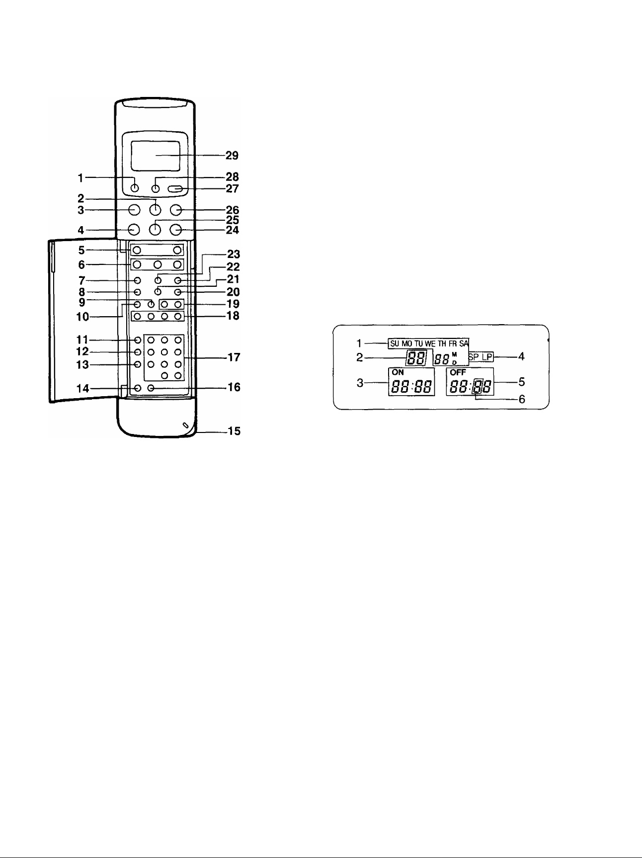
¡nfra-Red Remote Controller
18 Auto Play Buttons
19 Tracking/V-Lock and Buttons
20 Input Signal Selector
21 VTR/TV Selector
22 Reset Button
23 Tape Remain Button
24 Fast Forward ►►/Cue @ Button
25 Play Button (►)
26 Still Advance Button (ll^)
27 Transmit Button
28 Digital Scanner On/Off Button
29 Display
1 VTR On/Off Button
2 Stop Button (■)
3 Pause/Still Button (I I)
4 Rewind ◄◄/Review @ Button
5 Record Buttons
6 Slow Buttons
7 Clock/Counter Selector
8 Monitor Button
9 Time Search Button
10 Index Button
11 Programme Button
12 Next Button
13 Tape Speed Selector
14 Timer Record Button
15 Bar Code Reading Section
16 Clear Button
17 Programme Position (Channel) Selector Buttons
1 Date Display
2 Channel Display
3 Start Time Display
4 Tape Speed Indicator
5 End Time Display
6 Check Indicator
Power Source for the Remote Controller
■ The Remote Controller is powered by 2 I EC ‘‘R6″ size
batteries. The life of the batteries is about one year,
however, it depends on the frequency of use. inspect and
if necessary, replace the batteries once a year,
CAUTION FOR BATTERY REPLACEMENT
• Load the new batteries with their polarities (0 and 0)
aligned correctly.
• Do not apply heat to batteries, or internal short-circuit
may occur.
• If you do not intend to use the Remote Controller for a
long period of time, remove the batteries and store them
in a cool and dry place.
• Remove spent batteries immediately and dispose of
them.
• Do not use an old and a new batteries together. (Also
never use an alkaline battery with a manganese battery.)
(6)
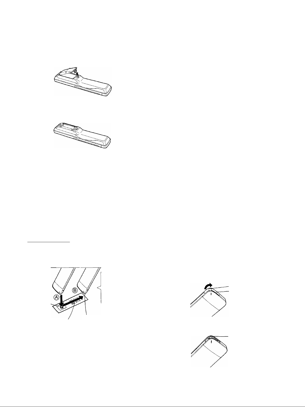
Infra-Red Remote Controller (Cont’d)
Load the batteries as follows:
1 Remove the battery compartment lid.
2 Place the batteries in the battery compartment as
indicated inside the battery compartment.
3 Replace the lid.
How to Operate the Remote Controller
(Digital Scanner)
Press the Digital Scanner On/Off Button to “ON”.
• If no operation is performed for more than 25 seconds
(4 minutes during setting of the clock time), the scanner
will automatically switch over to the power-saving
standby condition and the lamp will go off. (In this case, if
bar codes have already been read but not yet
transmitted to the VTR, the data will be cancelled.)
• When the lamp is not lit, press the button to turn it “ON”
again.
Tracing the Bar Codes
(A) Place the Remote Controller on the Small Box,
(B) Trace the bar code quickly in the direction of the
arrow.
Small Box
____________________________
The “Beep”
sound indicates
that the barcode
was read
completely.
• Treat the Programming Sheet with care. If the
sheet gets dirty or scratched, the bar code reading
may become impossible.
• Protect the Remote Controller from strong shocks
and vibration. Keep it away from water and places
with high temperature and humidity.
• If the bar code is traced slowly, it cannot be read
correctly.
• When there is no “Beep” sound, the reading of the
bar code is incomplete. Trace the bar code again.
• When using the Programming Sheet, put it on flat
surface: Reading the bar codes while holding it In
your hand or bending it, may result in incorrect
operation.
• Do not deviate from the bar code, nor stop tracing
halfway.
V______________________________________/
Note:
• The infra-red beam should be transmitted directly at the
Infra-red Remote Control Receiver on the front of the
VTR.
• Direct sunlight may interfere with the beam,
• The lightsensing angle of the Infra-red Remote Control
Receiver In the VTR Is about 30° for each side from the
centre.
•The unit should be used within a range of about 7 meters
from the front of the VTR,
Recommendation
After the programming of timer recording(s) is completed,
press the Digital Scanner On/Off Button so that the
indications in the Display disappear, in order to save
battery power.
When the Bar Codes Cannot be Read
Although the lamp in the tip of the Bar Code Reading
Section lights up:
• No figures appear in the Display
• No beep sounds is heard;
The tip of the Bar Code Reading Section is probably
clogged with dirt.
Cleaning
1 Remove the cap of the Bar Code Reading Section.
• Remove dirt and dust from the hole of the cap.
Hole
Cap
Bar Code
Trace the bar code
completely past the last bar.
Note:
The bar codes “VTR 1 ” and “VTR 2″ in the column
“REMOTE MODE” on the Programming Sheet cannot be
used with this unit.
•If the bar code “VTR 2” is traced by mistake, transmission
to the VTR becomes impossible. To remedy this
condition, trace the “VTR 1″ bar code. (The indication
“VTR 2” in the Display will disappear.)
Gently wipe the tip of the lamp with a soft cloth.
• Reattach the cap by inserting it until it locks with a
click.
Lamp
<7>
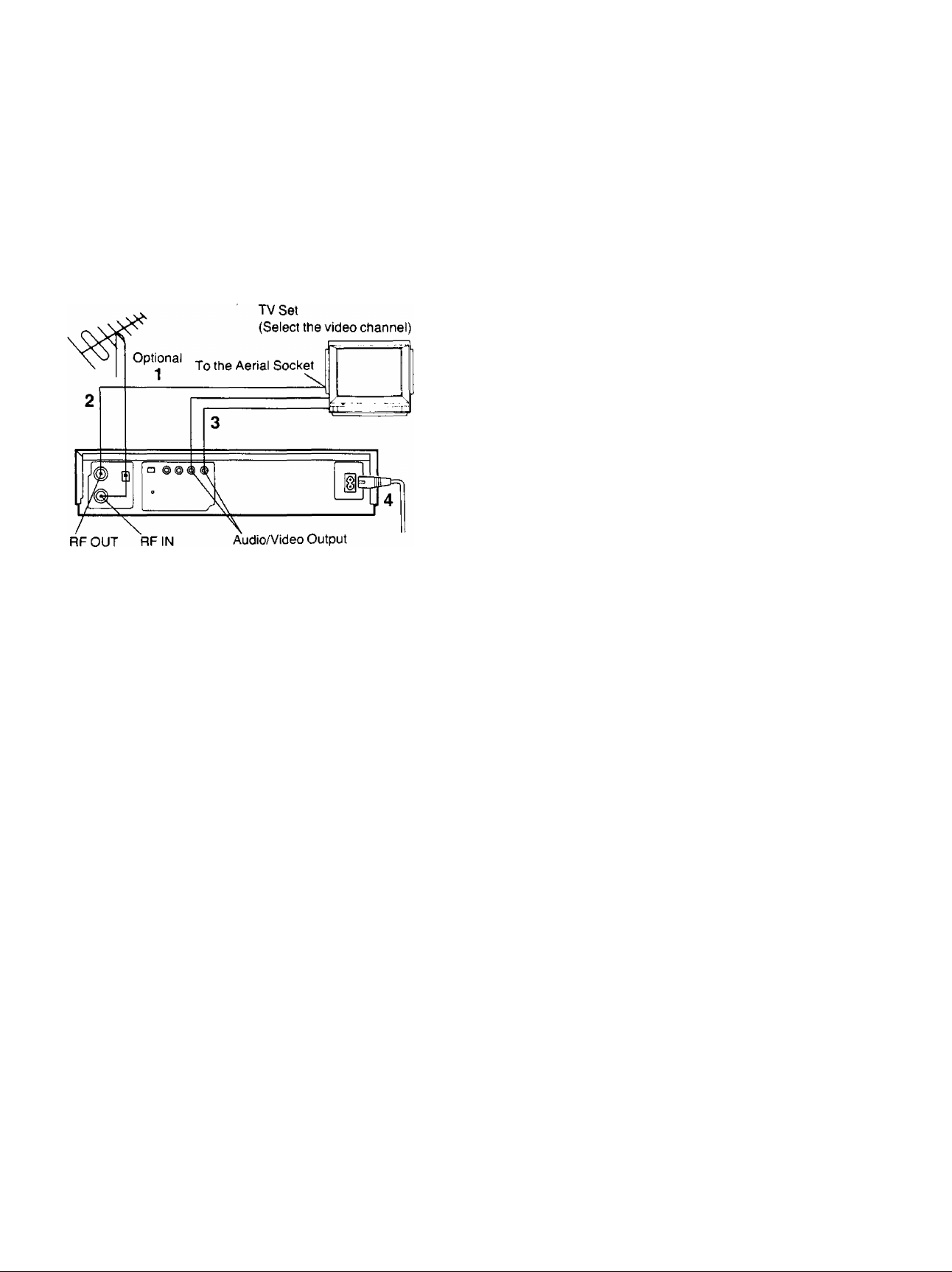
Installation
Connection to a TV Set
NV-J45A:
FOR YOUR SAFETY
Install any external aerial to AS 1417.1.
1 Connect the external aerial to the RF Input Socket on
the VTR.
2 Connect the aerial terminal on your TV set to the RF
Output Socket on the VTR with the supplied DIN-DIN
Coaxial Cable.
3 If the TV set is equipped with separate video and
audio input sockets, it is recommended to connect the
VTR to the TV set with separate video and audio
cables (not supplied).
4 Connect the AC Mains Lead to the AC Mains Socket
of the VTR to the mains outlet.
(8)
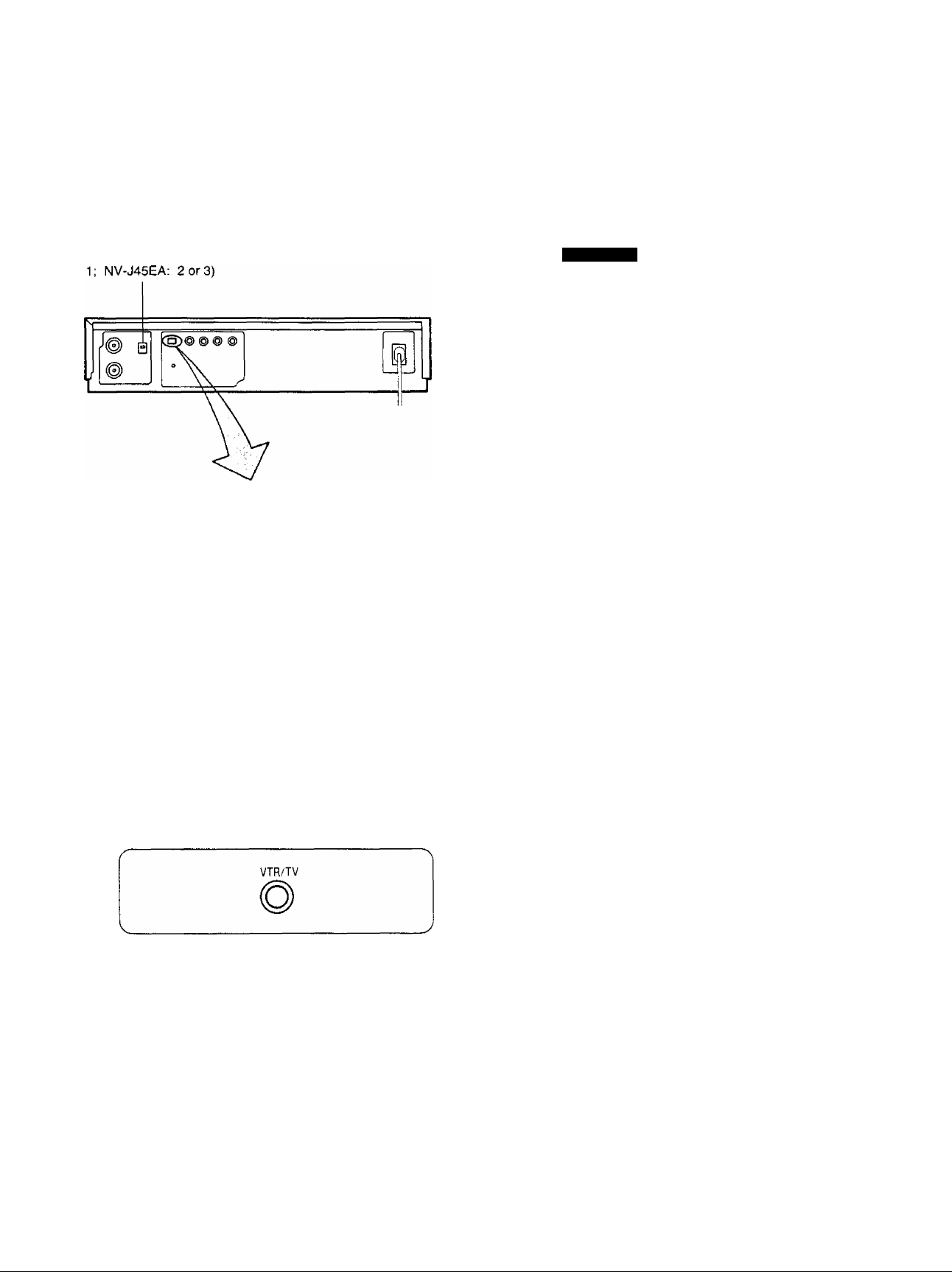
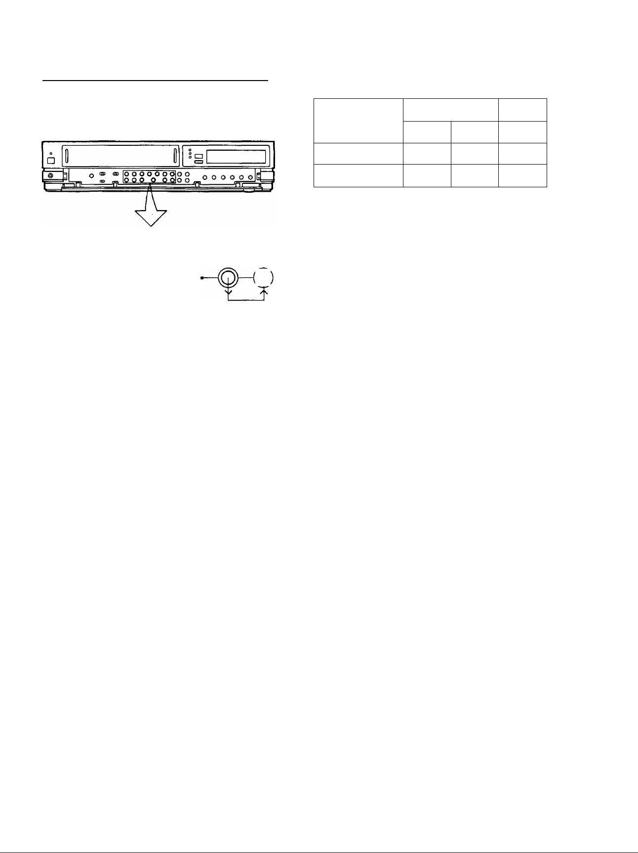
Tuning the TV Set to the Video Playback Channel
The adjustments described on this page are not
necessary, if the VTR is connected to the TV set via the
Video/Audio output sockets.
Video Playback Channel Selector
This switch is used to select the video playback channel
which is not occupied with any TV station.(NV-J45A: 0 or
□
OFF ON
TEST
SIGNAL
Tune your TV to VHF channel as shown below.
Confirm by your TV that the received test pattern is as
shown below.
NV-J45A: VHF channel 0 or 1*
NV-J45EA; VHF channel 2 or 3
NV-J45A only
*ln some areas
channel 0 may be
used by focal TV
station. In this case
switch to channel 1.
6 Set the Test Signal Switch to «OfT. Your TV is now
ready to receive the RF output signal from the VTR.
□
OFF ON
TEST
SIGNAL
7 To check, playback a pre-recorded tape and comfirm
that the picture quality is satisfactory.
1 Turn the TV set on and select the AV programme
position or another programme position that is not
occupied by any TV station.
2 Press the VTR On/Off Switch to turn the VTR On.
(FRONT SIDE)
o
VTR
• The corresponding indicator lights up.
3 Press the VTR/TV Selector to «VTR” position.
VTR Indicator will appear in the Multi-Function
Display.
4 Set the Test Signal Switch to «On”.
□
OFF ON
TEST
SK3NAL
<9)
Setting the Tuner in the VTR
The tuner in the VTR makes it possible to receive TV
broadcasts and to record these programmes without
having to turn on the TV set.
CLOCK PROG/
RECORDING TRACKING/V-LOCK TIMER REC VTR/TV
©—©° (Q)
PRESET/ 1
©—© ©“»^
FINE/MORMAL B/ND/AFC CLEAR
1-5
______________ T- jTL
3-2
NE
4-2
XT
D
1-3
Preparation
• Turn the TV set on and select the programme position
(channel) which you have tuned to the video playback
channel.
• Press the VTR On/Off Switch to turn the VTR on.
• Set the VTR/TV Selector to “VTR”.
PRE-PROGRAMMED TV CHANNELS (NV-J45A)
The local TV transmission channels 2, 7, 9 and 10
are factory-preset in this VTR. That is, if you can
receive television broadcasts on VHP channels 2, 7,
9 and 10, these are already tuned on the
programme positions with the matching numbers.
However, it is possible to cancel these presettings
and tune the local TV broadcast channels on any
desired programme positions.
For alternative settings and tuning of additional TV
broadcasts channels, follow the Tuning Procedure
below.
VHF
1
NV-J45A
NV-J45EA
The tuner in the VTR can be preset with up to 99 stations.
0-5
1-3
III
5A-11
4-11
UHF
U
21-69
21-69
4 Press the “-f” or Button until the picture of the
desired station on your TV is satisfactory.
• If the or Button is pressed while pressing
the Next Button, the stations will change quickly.
: Po
• The tuned station is automatically memorized.
Repeat steps 2-4 for each channel you want to tune to a
station.
During the station search
(The position indication
flashes on and off.)
Tuned condition
5 Press the Preset/Fine/Normal Button twice.
The indication on the Multi-Function Display changes
back to the previous indication.
Fine Tuning Procedure
If fine tuning is necessary, for example for a weak station
which is close to a strong station:
1 Press the Preset/Fine/Normal Button twice.
Tuning Procedure
1 Press the Preset/Fine/Normal Button on the VTR.
The indication on the Multi-Function Display changes
from the clock indication to the position indication.
2 Press the Channel Up or Down Button to select a
programme position (channel) which you want to tune
to a TV station.
3 Press the Band/AFC Button to select the “I”, “III” or
“U» position.
Display of the programme
positions 1-99
Indication of the
selected TV band
2 Press the “-f” or Button to obtain the best tuning
condition.
• “AFC” Indicator will not be displayed.
• To return the tuning to its former state, press the
Band/AFC Button.
3 Press the Preset/Fine/Normal Button.
<10>
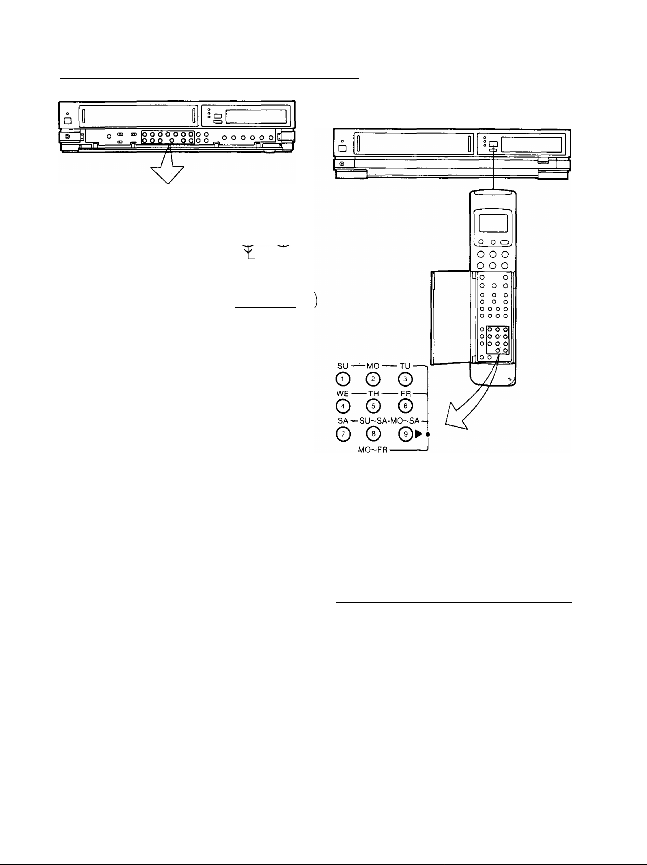
Setting the Tuner in the VTR (Cont’d)
How to Select the Programme Position (Channel) on
the Remote Controller
CLOCK PROG/
Oh©-s@-@ ©-©•©
PRESET/ t
FINE/NORMAL BAND/AFC CUAR
1*4
RECORDING TRACKING/V-LOCK TIMER REG VTR/TV
_____________
a _ 1
NEXT
3-2
2.2
1-3
Blanking of Unoccupied Programme Position
\t\onsf~S’jC’f7n<}Je
1 Press the Preset/Fine/Norma! Button.
2 Press the Channel Up or Down Button to select a
programme position (channel) which you do not want
to tune to a TV station.
3 Press the Clear Button (“—” will be displayed in the
Programme Position Indication).
^
• Repeat steps 2 and 3 for any programme positions
on which no stations are to be tuned. Afterwards,
these programme positions will be skipped during
Up/Down selection of the programme position.
4 Press the Preset/Fine/Normal Button twice.
Cancelling the Clear Function (Blanking)
1 Press the Preset/Fine/Normal Button.
2 To cancel the blanking of a programme position,
select that programme position on the VTR and then
press the Clear Button.
3 Press the Preset/Fine/Normal Button twice.
©
0
select channel
1-9
10
20
11-99
for example 32
If more than 5 seconds pass between the first, second and
third push, the channel will not be changed normally.
To select the “A1″ programme position;
Press the Input Signal Selector.
To select the signals which are input via Audio Input
Socket and Video Input Socket, select the “A1 ’’
programme position.
press button
respective channel
©-►©-►0
©_►©_»©
©_► 0-»0
(11)
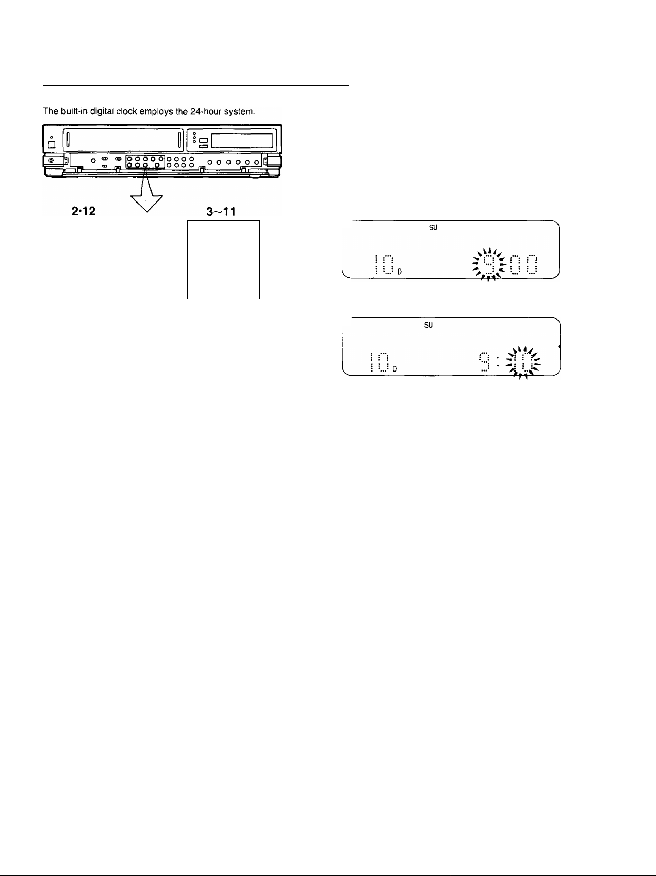
Setting the Clock to the Present Time
7 Press the or Button to set the date.
8 Press the Next Button,
9 Press the “+” or Button to set the hour.
CLOCK PROG/Baaa RECORDING
TRACKING/V-LOCK
r
^ su
^ i i i ^ ; I ■ J J
__
__ ____ _ ____ _ ____ _ ____
!£
OhOH©-
PRFSFT/ 1
©—©—0-
FINE/NORMAL BA’ND/AFC CLEAR
For Example: Set the clock for Sunday, October 10,
___________
• Connect the VTR to the mains outlet.
• Press the VTR On/Off Switch to turn the VTR On.
1999, 9:10.
___________________
O ©
NEXT
1 When connecting this VTR to the mains or after a
long power failure, the indications flash.
i i • : ; ! s ^
2 Press the Clock Button to start the date and time
setting.
SA
> t I : : r-
3 Press the or Button to set the year.
FR
^ z : :
4 Press the Next Button.
5 Press the «+” orButton to set the month.
FR
-! !
10 Press the Next Button.
11 Press the “+” or Button to set the minute.
r
12 Press the Clock Button when the present time
becomes exactly 9:10’00».
su
:
At every push of the Next Button, the flashing indication
changes in the following order.
YEAR^MONTH^DATE^HOUR-^MINUTE
• In case of a power failure, the timer back-up
system maintains the clock operation and timer
content for at least 60 minutes. However,
depending on the charging time and the memory
content, the back-up time may be considerably
longer. However, it takes more than 60 minutes for
the back-up circuit to become operational, after the
VTR is connected to the mains.
•The Timer Record Function should be set to “Off”,
otherwise the VTR cannot be operated normally. In
this case, the Timer Record Indicator “Hi” will flash
to warn you.
• During date setting, the corresponding day is
simultaneously set.
• The clock/timer of the VTR is programmed with the
calendar up to the end of the year 2087.
The indications 88-99 are for the years 1988-1999.
The indications 00-87 are for the years 2000-2087.
6 Press the Next Button.
(12)
Setting the Clock to the Present Time (Cont’d)
Setting the Clock to the Present Time Using the Bar
Codes
1
B———————___
X til
II
rr III
lili
h ilil
X INI
lili
>: ili|
1i lili
■ «II a iiii
« III
xi m
-1 «III
«1 illl
111 X. lili
M
i
Xi Ull
x^ lili
a iti
: Jiti
Ull
« 4111
— IIH
i’i 111
U. Ill
xj illl
h IlU
M’ ihl
X: IlU
; iiiih
Mil
IM M
Ifl
it w
tur
itttt
.<: m
i’i t’W
:’i mi
I un
<! im
‘1 ilil
•1 lili
■! lili Xi lili
• lili
lili ‘X lili
r lili
l> lili
l»i lili
lili
< lili
x lili
X lili
X tlll
r ilU
m
Preparation
• Press the Digital Scanner On/Off Button to turn it “ON”.
1
Trace the bar code “SETTING OF THE CLOCK”.
SETTING OF THE CLOCK
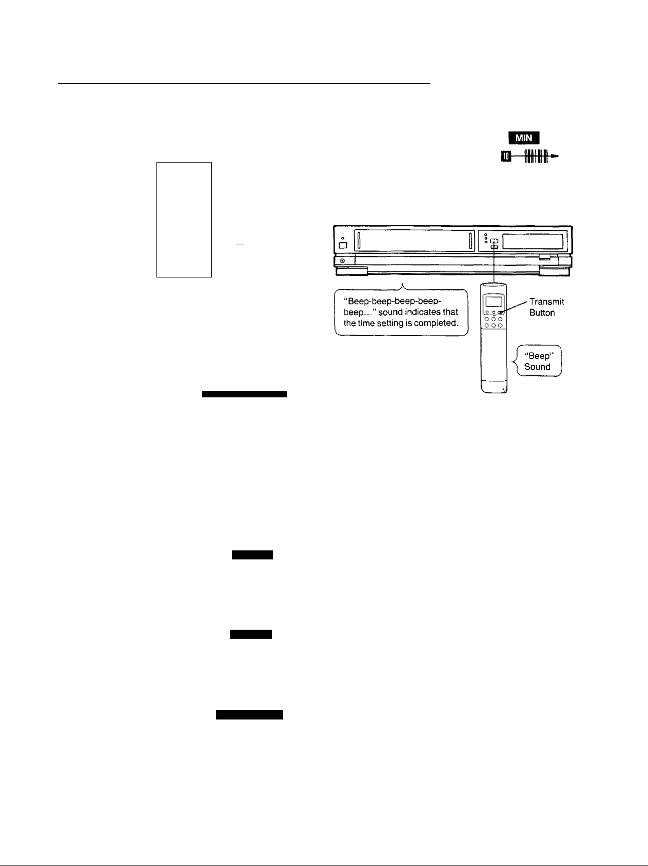
6 Trace the bar code for the minute (MIN).
. m
5
■ <(j
7
Press the Transmit Button (Remote Controller) and
then confirm that the time is displayed in the
Multi-Function Display of the VTR.
□-
2
Trace the bar code for the year (YEAR).
39
1IMQ-
3
Trace the bar code for the month (MONTH).
MONTH
m-m
4
Trace the bar code for the day of the month (DATE).
2 DATE
0MI»
5
Trace the bar code for the hour (START TIME).
8 Press the Digital Scanner On/Off Button to turn it
“OFF”.
• if the transmission was not received correctly, the
“Beep-Beep, Beep-Beep” sound from the VTR will warn
you. In this case, perform transmission again.
• If the Remote Controller is left with no operation
performed for more than 4 minutes, it will automatically
switch over to the power-saving standby condition and
the lamp in the reading tip goes out. In this case, bar
codes that have already been read (but not yet
transmitted to the VTR) will be cancelled.
• The bar codes “SETTING OF THE CLOCK”, “YEAR”
and «MONTH” are located on page 3 of the
Programming Sheet.
Q-nn 9
JUU •
3 START TIME
(13)
Loading…
View the manual for the Panasonic NV-J45EE here, for free. This user manual comes under the category video cassette recorders and has been rated by 4 people with an average of a 8.7. This manual is available in the following languages: -. Do you have a question about the Panasonic NV-J45EE?
Ask your question here
Frequently asked questions
Can’t find the answer to your question in the manual? You may find the answer to your question in the FAQs about the Panasonic NV-J45EE below.
Is the manual of the Panasonic NV-J45EE available in English?
Unfortunately, we do not have the manual for the Panasonic NV-J45EE available in English. This manual is available in -.
Is your question not listed? Ask your question here
- Topics
- manualsbase, manuals,
- Collection
- manuals_panasonic; manuals; additional_collections
- Language
- English
- Item Size
- 27.4M
- Addeddate
- 2020-08-17 09:19:26
- Identifier
- manualsbase-id-464427
- Identifier-ark
- ark:/13960/t25b97t5t
- Ocr
- ABBYY FineReader 11.0 (Extended OCR)
- Page_number_confidence
- 100.00
- Ppi
- 400
- Scanner
- Internet Archive Python library 1.9.4
plus-circle Add Review
plus-circle Add Review
comment
Reviews
There are no reviews yet. Be the first one to
write a review.
221
Views
1
Favorite
DOWNLOAD OPTIONS
download 1 file
ABBYY GZ download
Temporarily Unavailable
DAISY
For users with print-disabilities
Temporarily Unavailable
EPUB
download 1 file
FULL TEXT download
download 1 file
ITEM TILE download
download 1 file
PAGE NUMBERS JSON download
download 1 file
PDF download
download 1 file
PDF WITH TEXT download
download 1 file
SINGLE PAGE PROCESSED JP2 ZIP download
download 1 file
TORRENT download
download 13 Files
download 6 Original
SHOW ALL
IN COLLECTIONS
Manuals: Panasonic
The Manual Library
Additional Collections
Uploaded by
chris85
on

Vi
■ f r S i : ■ V .
i;* ‘ ‘
■^Vv’ V’
V 4-‘^ ■’■■■?’ i- i .’;
i:
; v
ir’
:. ,
■
V
-V- V ;
.;. ;Ì ¥■’*■ i if-
.5 ,’.. ,’.. .■:
‘..
■
. ..
.
¡: ¡;- f ji,.- V. „ i i ‘■ ■ ■ ■
■
■
‘ :
.
-i-
!:.-^ . :
-r «. — ■
; .; ••
^.. ‘1-.
• ‘K-
> i’., :
‘ i ,- -i ..
VfS.
f «■
Video Cassette Recorder
N V* J45series
Operating Instructions
;■■ ■■
.r? y ■■
4
-‘… ■ ■■..■…
:■ is-‘»» V- s: f f f f:—^; ;. ;.
—
i» f. S.:f .i. i. .-
■ 4′ i
, , .
VMS
VQT4050
mu NTSC 4.43
Before attempting to connect, operate
or adjust this product, ptease read
these instructions completely.
Хорошее руководство по эксплуатации
Законодательство обязывает продавца передать покупателю, вместе с товаром, руководство по эксплуатации Panasonic NV-J45 Series. Отсутствие инструкции либо неправильная информация, переданная потребителю, составляют основание для рекламации в связи с несоответствием устройства с договором. В законодательстве допускается предоставлении руководства в другой, чем бумажная форме, что, в последнее время, часто используется, предоставляя графическую или электронную форму инструкции Panasonic NV-J45 Series или обучающее видео для пользователей. Условием остается четкая и понятная форма.
Что такое руководство?
Слово происходит от латинского «instructio», тоесть привести в порядок. Следовательно в инструкции Panasonic NV-J45 Series можно найти описание этапов поведения. Цель инструкции заключается в облегчении запуска, использования оборудования либо выполнения определенной деятельности. Инструкция является набором информации о предмете/услуге, подсказкой.
К сожалению немного пользователей находит время для чтения инструкций Panasonic NV-J45 Series, и хорошая инструкция позволяет не только узнать ряд дополнительных функций приобретенного устройства, но и позволяет избежать возникновения большинства поломок.
Из чего должно состоять идеальное руководство по эксплуатации?
Прежде всего в инструкции Panasonic NV-J45 Series должна находится:
— информация относительно технических данных устройства Panasonic NV-J45 Series
— название производителя и год производства оборудования Panasonic NV-J45 Series
— правила обслуживания, настройки и ухода за оборудованием Panasonic NV-J45 Series
— знаки безопасности и сертификаты, подтверждающие соответствие стандартам
Почему мы не читаем инструкций?
Как правило из-за нехватки времени и уверенности в отдельных функциональностях приобретенных устройств. К сожалению само подсоединение и запуск Panasonic NV-J45 Series это слишком мало. Инструкция заключает ряд отдельных указаний, касающихся функциональности, принципов безопасности, способов ухода (даже то, какие средства стоит использовать), возможных поломок Panasonic NV-J45 Series и способов решения проблем, возникающих во время использования. И наконец то, в инструкции можно найти адресные данные сайта Panasonic, в случае отсутствия эффективности предлагаемых решений. Сейчас очень большой популярностью пользуются инструкции в форме интересных анимаций или видео материалов, которое лучше, чем брошюра воспринимаются пользователем. Такой вид инструкции позволяет пользователю просмотреть весь фильм, не пропуская спецификацию и сложные технические описания Panasonic NV-J45 Series, как это часто бывает в случае бумажной версии.
Почему стоит читать инструкции?
Прежде всего здесь мы найдем ответы касательно конструкции, возможностей устройства Panasonic NV-J45 Series, использования отдельных аксессуаров и ряд информации, позволяющей вполне использовать все функции и упрощения.
После удачной покупки оборудования/устройства стоит посвятить несколько минут для ознакомления с каждой частью инструкции Panasonic NV-J45 Series. Сейчас их старательно готовят или переводят, чтобы они были не только понятными для пользователя, но и чтобы выполняли свою основную информационно-поддерживающую функцию.