
Инструкция по эксплуатации Iнструкцiя з експлуатацiї Blu…
Система домашнего кинотеатра blu-ray, Система домашнього кінотеатру Чат поддержки
- Изображение
- Текст
EE
VQT3M07
until
2011/02/07
Инструкция по эксплуатации
Iнструкцiя з експлуатацiї
Blu-ray
TM
система домашнего кинотеатра
Blu-ray
TM
система домашнього кінотеатру
Model No.
SC-BTT775
SC-BTT270
На иллюстрации показана модель SC-BTT775.
На ілюстрації зображено модель SC-BTT775.
Уважаемый покупатель
Благодарим Вас за покупку данного изделия.
Для обеспечения его оптимальной функциональности и безопасности, пожалуйста, внимательно прочитайте настоящую
инструкцию.
Перед подсоединением, эксплуатацией или настройкой данного изделия полностью прочитайте все инструкции.
Сохраните данное руководство для последующего использования.
Шановний покупець
Дякуємо Вам за придбання цього виробу.
Задля забезпечення оптимальної та безпечної роботи пристрою, будь ласка, уважно прочитайте цю iнструкцiю.
Перед підключенням, користуванням або настройкою даного пристрою просимо уважно ознайомитись із цією інструкцією.
Збережіть даний посібник для звертання до нього у майбутньому.
SC-BTT775_270_EE_VQT3M07_rus.book 1 ページ 2011年1月20日 木曜日 午後4時11分
2
VQT3M07
Getting started
Меры предосторожности
Устройство
≥ Во избежание возникновения пожара, удара
электрическим током или повреждения изделия
jберегите это устройство от воздействия дождя,
влажности, капель и брызг.
jНе ставьте на это устройство емкости с водой,
например вазы.
jИспользуйте только рекомендуемое дополнительное
оборудование.
jНе снимайте крышки.
jНе пытайтесь самостоятельно чинить устройство.
Обращайтесь к квалифицированным специалистам.
jСледите за тем, чтобы внутрь устройства не попадали
металлические предметы.
jНе ставьте на устройство тяжелые предметы.
jНе прикасайтесь к разъемам колонок во время их
работы. Статическое электричество может вызвать
неисправность.
Сетевой шнур
≥ Во избежание возникновения пожара, удара
электрическим током или повреждения изделия
jУбедитесь в том, чтобы подаваемое напряжение
питания соответствовало значению, указанному на
корпусе устройства.
jУбедитесь в том, что штепсельная вилка полностью
вставлена в розетку.
jНе тяните и не сгибайте шнур, не ставьте на него
тяжелые предметы.
jНе прикасайтесь к штепсельной вилке влажными
руками.
jПри вынимании штепсельной вилки следует браться за
корпус вилки.
jНе пользуйтесь поврежденной штепсельной вилкой
шнура питания или розеткой.
≥ Размещайте устройство таким образом, чтобы случае
каких-либо проблем можно было незамедлительно
отключить шнур питания переменного тока от
штепсельной розетки.
Маленький объект
≥ Храните карту памяти в недоступном для детей месте во
избежание ее проглатывания.
≥ Опасность проглатывания. Храните винты в
недоступном для детей месте.
Устройство
≥ В этом устройстве используется лазер. Применение
регулировок и настроек или выполнение процедур,
отличающихся от описанных в данном руководстве,
может привести к опасному облучению.
≥ Не помещайте источники открытого огня, такие как
горящие свечи, на устройство.
≥ Во время эксплуатации данное устройство может
подвергаться действию радиопомех, вызванных
мобильными телефонами. Для устранения помех
увеличьте расстояние между устройством и мобильным
телефоном.
≥ Данное устройство предназначено для эксплуатации в
умеренном климате.
Размещение
≥ Данное устройство следует устанавливать на ровную
поверхность.
≥ Во избежание возникновения пожара, удара
электрическим током или повреждения изделия
jНе устанавливайте и не размещайте данное устройство в
книжном стеллаже, встроенном шкафу или в другом
ограниченном пространстве. Убедитесь в том, что для
устройства обеспечена хорошая вентиляция.
jНе закрывайте вентиляционные отверстия устройства
газетами, скатертями, шторами и подобными предметами.
jБерегите устройство от действия прямых солнечных
лучей, высокой температуры, высокой влажности и
сильных вибраций.
Батарейки
≥ В случае неправильной замены элемента питания
существует опасность взрыва. Используйте для замены
исключительно рекомендованный изготовителем тип
элемента питания.
≥ Неправильное обращение с элементами питания может
привести к вытеканию электролита и стать причиной пожара.
jНе используйте старые и новые элементы питания или
их различные типы вместе.
jНе нагревайте и не подвергайте воздействию огня.
jНе оставляйте элементы питания на длительное время в
автомобиле с закрытыми окнами и дверями на солнце.
jНе разбирайте и не замыкайте накоротко.
jНе перезаряжайте щелочные или марганцевые
элементы питания.
jНе используйте батарейки со снятой оболочкой.
jЕсли вы не собираетесь пользоваться пультом
дистанционного управления в течение продолжительного
времени, следует извлечь из него элементы питания.
Храните их в прохладном темном месте.
≥ При утилизации элементов питания запросите в местных
органах власти или у продавца информацию по
правильному способу утилизации.
ПРЕДУПРЕЖДЕНИЕ
ВНИМАНИЕ!
SC-BTT775_270_EE_VQT3M07_rus.book 2 ページ 2011年1月20日 木曜日 午後4時11分
3
VQT3M07
-Если Вы увидите такой символ-
(Внутри аппарата)
Информация по обращению с отходами для стран,
не входящих в Европейский Союз
Действие этого символа распространяется
только на Европейский Союз.
Если вы собираетесь выбросить данный
продукт, узнайте в местных органах власти
или у дилера, как следует поступать с
отходами такого типа.
Беспроводное сетевое подключение может
использоваться только в России.
Малайзия
[BTT775]
[BTT270]
SC-BTT775_270_EE_VQT3M07_rus.book 3 ページ 2011年1月20日 木曜日 午後4時11分
4
VQT3M07
DivX
®
, DivX Certified
®
и другие логотипы являются товарными
знаками DivX, Inc. и используются по лицензии.
DivX
®
, DivX Certified
®
and associated logos are trademarks of DivX, Inc.
and are used under license.
Логотип Wi-Fi CERTIFIED является сертификационным знаком Wi-Fi
Alliance.
Java и все торговые марки и логотипы, основанные на Java
являются торговыми марками или зарегистрированными торговыми
марками “Sun Microsystems, Inc.” в США и/или других странах.
Изготовлено по лицензии компании Dolby Laboratories. “Долби”,
“Pro Logic” и знак в виде двойной буквы D являются товарными
знаками компании Dolby Laboratories.
Изготовлено по лицензии по патентам США №: 5,451,942;
5,956,674; 5,974,380; 5,978,762; 6,226,616; 6,487,535; 7,392,195;
7,272,567; 7,333,929; 7,212,872, а также согласно прочим патентам
в США и в мире, выданным или ожидаемым.
DTS и знак являются зарегистрированным торговыми марками, &
DTS-HD, DTS-HD Master Audio | Essential и логотипы DTS являются
торговыми марками DTS, Inc.
Изделие включает программное обеспечение. © DTS, Inc. Все
права защищены.
Данный пункт включает технологию защиты от копирования,
которая охраняется патентами США и другими правами на
интеллектуальную собственность Rovi Corporation. Инженерный
анализ и разборка запрещены.
HDMI, логотип HDMI и High-Definition Multimedia Interface являются
торговыми марками или зарегистрированными торговыми марками
HDMI Licensing LLC в Соединенных Штатах и других странах.
Данный продукт лицензирован в соответствии с патентом AVC и
патентом VC-1 личного и некоммерческого использования
потребителем для (i) кодирования видео в соответствии с
визуальным стандартом AVC и VC-1 (“AVC/VC-1 Video”) и/или
(ii) декодирования видео AVC/VC-1, которое было закодиировано
пользователем в процессе личной и некоммерческой деятельности
и/или было получено от видеопровайдера, лицензированного на
предоставление видео AVC/VC-1 Video. Для другого использования
лицензия не приедоставляется и не подразумевается.
Дополнительную информацию можно получить в MPEG LA, LLC.
См. http://www.mpegla.com.
HDAVI Control™ является торговой маркой компании Panasonic
Corporation.
VIERA CAST является торговой маркой Panasonic Corporation.
Texнолoгия кодирования звука MPEG Layer-3 лицензирована у
Fraunhofer IIS и Thomson.
“AVCHD” и логотип “AVCHD” являются торговыми марками
Panasonic Corporation и Sony Corporation.
Логотип SDXC является товарным знаком SD-3C, LLC.
“DVD Logo” — товарный знак корпорации DVD Format/Logo
Licensing Corporation.
YouTube и Picasa являются товарными знаками Google, Inc.
Windows является товарным знаком или зарегистрированным
товарным знаком Microsoft Corporation в США и других странах.
“Made for iPod” и “Made for iPhone” значит, что электронные
дополнительные принадлежности были разработаны специально
для подключения к iPod или iPhone, и сертифицированы
разработчиком на соответствие стандартам технических
характеристик Apple.
Компания Apple не несет ответственности за эксплуатацию
данного устройства или за его соответствие стандартам
безопасности и регулятивным нормам.
Примите во внимание, что использование данной
принадлежности с iPod или iPhone может повлиять на качество
беспроводного соединения.
iPhone, iPod, iPod classic, iPod nano и iPod touch являются
торговыми марками компании Apple Inc., зарегистрированными в
США и других странах.
DLNA, the DLNA Logo and DLNA CERTIFIED are trademarks, service
marks, or certification marks of the Digital Living Network Alliance.
This product incorporates the following software:
For the software categorized as (3) and (4), please refer to the terms
and conditions of GPL v2 and LGPL v2.1, as the case may be at
http://www.gnu.org/licenses/old-licenses/gpl-2.0.html and
http://www.gnu.org/licenses/old-licenses/lgpl-2.1.html.
In addition, the software categorized as (3) and (4) are copyrighted by
several individuals. Please refer to the copyright notice of those
individuals at
http://www.am-linux.jp/dl/AWBPP11
The GPL/LGPL software is distributed in the hope that it will be useful,
but WITHOUT ANY WARRANTY, without even the implied warranty of
MERCHANTABILITY or FITNESS FOR A PARTICULAR PURPOSE.
At least three (3) years from delivery of products, Panasonic will give to
any third party who contacts us at the contact information provided
below, for a charge no more than our cost of physically performing
source code distribution, a complete machine-readable copy of the
corresponding source code covered under GPL v2/LGPL v2.1.
Contact Information
cdrequest@am-linux.jp
Source code is also freely available to you and any other member of
the public via our website below.
http://www.am-linux.jp/dl/AWBPP11
the software developed independently by or for Panasonic
Corporation,
the software owned by third party and licensed to Panasonic
Corporation,
the software licensed under the GNU General Public License,
Version 2 (GPL v2),
the software licensed under the GNU LESSER General Public
License, Version 2.1 (LGPL v2.1) and/or,
open sourced software other than the software licensed under the
GPL v2 and/or LGPL v2.1
(1)
(2)
(3)
(4)
(5)
This product includes software developed by the OpenSSL Project
for use in the OpenSSL Toolkit.
(http://www.openssl.org/)
This product includes software developed by the University of
California, Berkeley and its contributors.
FreeType code.
The Independent JPEG Group’s JPEG software.
For the software categorized as (5) includes as follows.
1.
2.
3.
4.
SC-BTT775_270_EE_VQT3M07_rus.book 4 ページ 2011年1月20日 木曜日 午後4時11分
Перед эксплуата-
цией
Радио
Телевизор
Дополнительные
операции
Ссылки
Воспроизведение
Другие устройства
Дополнительные настройки колонок
5
VQT3M07
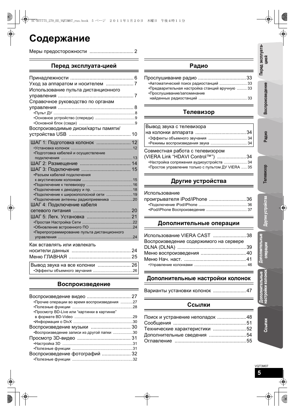
Содержание
Меры предосторожности ………………………….. 2
Перед эксплуата-цией
Принадлежности ………………………………………. 6
Уход за аппаратом и носителем ……………….. 7
Использование пульта дистанционного
управления ………………………………………………. 7
Справочное руководство по органам
управления ………………………………………………. 8
•Пульт ДУ ………………………………………………………………..8
•Основное устройство (спереди) ………………………………9
•Ocнoвнoй блoк (сзади) ……………………………………………9
Воспроизводимые диски/карты памяти/
устройства USB ……………………………………… 10
Как вставлять или извлекать
носители данных ……………………………………. 24
Меню ГЛАВНАЯ ……………………………………… 25
Воспроизведение
Воспроизведение видео ………………………….. 27
•Прочие операции во время воспроизведения ………..27
•Полезные функции ……………………………………………….28
•Просмотр BD-Live или “картинки в картинке”
в формате BD-Video ……………………………………………..29
•Информация о DivX ………………………………………………30
Воспроизведение музыки ……………………….. 30
•Воспроизведение записи из другой папки ………………30
Просмотр 3D-видео ………………………………… 31
•Настройка 3D ……………………………………………………….31
•Полезные функции ……………………………………………….31
Воспроизведение фотографий ………………… 32
•Полезные функции ……………………………………………….32
Радио
Прослушивание радио ……………………………..33
•Автоматический поиск радиостанций ……………………. 33
•Предварительная настройка станций вручную ……… 33
•Прослушивание/запоминание
найденных радиостанций …………………………………….. 33
Телевизор
Совместная работа с телевизором
(VIERA Link “HDAVI Control™”) …………………34
•Настройка сопряжения аудиоустройств ………………… 34
•Простое управление только с пультом ДУ VIERA ….. 35
Другие устройства
Использование
проигрывателя iPod/iPhone ………………………36
•Подключение iPod/iPhone …………………………………….. 36
•iPod/iPhone Воспроизведение ………………………………. 37
Дополнительные операции
Использование VIERA CAST ……………………38
Воспроизведение содержимого на сервере
DLNA (DLNA) …………………………………………..39
Меню воспроизведения ……………………………40
Меню Нач. наст. ………………………………………41
•Управление колонками ………………………………………… 46
Дополнительные настройки колонок
Варианты установки колонок ……………………47
Ссылки
Поиск и устранение неполадок …………………48
Сообщения ……………………………………………..51
Технические характеристики ……………………52
Дополнительные сведения ………………………54
Оглавление …………………………………………….55
ШАГ 1: Подготовка колонок ……………………. 12
•Установка колонок ………………………………………………..12
•Подготовка кабелей и осуществление
подключения ………………………………………………………..13
ШАГ 2: Размещение ………………………………. 14
ШАГ 3: Подключение ……………………………… 15
•Разъем кабелей подключения
к акустическим колонкам ……………………………………….15
•Подключение к телевизору ……………………………………16
•Подключение к декодеру и пр. ………………………………18
•Подключение к широкополосной сети ……………………19
•Подключение антенны радиоприемника ………………..20
ШАГ 4: Подключение кабеля
сетевого питания …………………………………… 20
ШАГ 5: Легк. Установка ………………………….. 21
•Простая Настройка Сети ……………………………………….22
•Обновление встроенного ПО …………………………………24
•Перепрограммирование пульта дистанционного
управления …………………………………………………………..24
Вывод звука на все колонки …………………… 26
•Эффекты объемного звучания ………………………………26
Вывод звука с телевизора
на колонки аппарата ……………………………….34
•Эффекты объемного звучания …………………………….. 34
•Режимы воспроизведения звука …………………………… 34
SC-BTT775_270_EE_VQT3M07_rus.book 5 ページ 2011年1月20日 木曜日 午後4時11分
6
VQT3M07
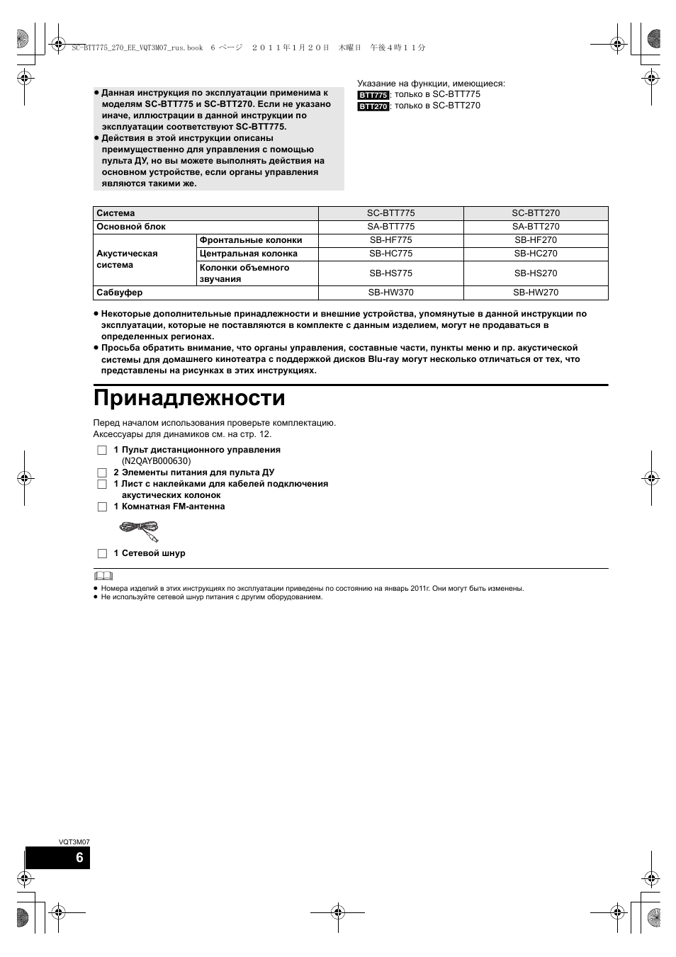
Перед началом эксплуатации
Указание на функции, имеющиеся:
[BTT775]: только в SC-BTT775
[BTT270]: только в SC-BTT270
≥ Некоторые дополнительные принадлежности и внешние устройства, упомянутые в данной инструкции по
эксплуатации, которые не поставляются в комплекте с данным изделием, могут не продаваться в
определенных регионах.
≥ Просьба обратить внимание, что органы управления, составные части, пункты меню и пр. акустической
системы для домашнего кинотеатра с поддержкой дисков Blu-ray могут несколько отличаться от тех, что
представлены на рисунках в этих инструкциях.
Принадлежности
Перед началом использования проверьте комплектацию.
Аксессуары для динамиков см. на стр. 12.
≥ Номера изделий в этих инструкциях по эксплуатации приведены по состоянию на январь 2011г. Они могут быть изменены.
≥ Не используйте сетевой шнур питания с другим оборудованием.
≥ Данная инструкция по эксплуатации применима к
моделям SC-BTT775 и SC-BTT270. Если не указано
иначе, иллюстрации в данной инструкции по
эксплуатации соответствуют SC-BTT775.
≥ Действия в этой инструкции описаны
преимущественно для управления с помощью
пульта ДУ, но вы можете выполнять действия на
основном устройстве, если органы управления
являются такими же.
Система
SC-BTT775
SC-BTT270
Основной блок
SA-BTT775
SA-BTT270
Акустическая
система
Фронтальные колонки
SB-HF775
SB-HF270
Центральная колонка
SB-HC775
SB-HC270
Колонки объемного
звучания
SB-HS775
SB-HS270
Сабвуфер
SB-HW370
SB-HW270
∏ 1 Пульт дистанционного управления
(N2QAYB000630)
∏ 2 Элементы питания для пульта ДУ
∏ 1 Лист с наклейками для кабелей подключения
акустических колонок
∏ 1 Комнатная FM-антенна
∏ 1 Сетевой шнур
SC-BTT775_270_EE_VQT3M07_rus.book 6 ページ 2011年1月20日 木曜日 午後4時11分
Уход за аппаратом и носителем, Использование пульта дистанционного управления, Протирайте аппарат мягкой сухой тканью
При утилизации или передаче аппарата Чат поддержки
- Изображение
- Текст
Перед эксплуата-
цией
7
VQT3M07
Уход за аппаратом и
носителем
∫ Протирайте аппарат мягкой сухой
тканью
≥ Ни в коем случае не используйте для очистки спирт,
растворитель или бензин.
≥ Прежде чем воспользоваться тканями, прошедшими
химическую обработку, внимательно прочтите
инструкции к ним.
∫ Очищайте линзу с помощью
очистителя для линз
∫ Очищайте диски
Протрите влажной тканью и затем вытрите насухо.
∫ Меры предосторожности при
обращении с диском и картой
≥ Берите диски за края, чтобы не поцарапать их и не
оставить отпечатков пальцев.
≥ Не приклеивайте этикетки или стикеры на диски.
≥ Не применяйте чистящие аэрозоли, бензин,
растворители, жидкости для снятия статического
электричества и прочие растворители.
≥ Удаляйте грязь, воду и посторонние вещества с
терминалов на задней стороне карты.
≥ Не используйте следующие диски:
jДиски со следами от клейких материалов от стикеров и
этикеток (взятые в прокат и т.д.).
jПоцарапанные или треснувшие диски.
jДиски нестандартной формы, например, в виде
сердца.
∫ При утилизации или передаче
аппарата
Аппарат может содержать пользовательские настройки.
Если вы утилизируете или передаете аппарат, то
выполните процедуру возврата всех настроек к заводским
и удаления пользовательских настроек. (> 48, “Для
возвращения всех настроек к заводским.”)
≥ Хронология операций может быть записана в памяти
данного аппарата.
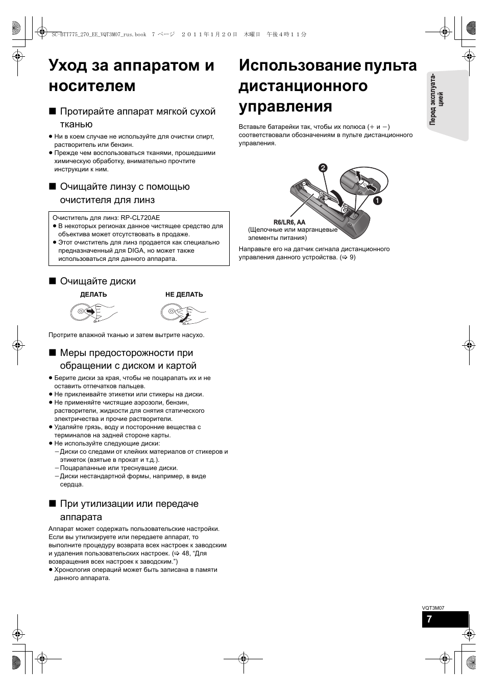
Использование пульта
дистанционного
управления
Вставьте батарейки так, чтобы их полюса (i и j)
соответствовали обозначениям в пульте дистанционного
управления.
Направьте его на датчик сигнала дистанционного
управления данного устройства. (> 9)
Очиститель для линз: RP-CL720AE
≥ В некоторых регионах данное чистящее средство для
объектива может отсутствовать в продаже.
≥ Этот очиститель для линз продается как специально
предназначенный для DIGA, но может также
использоваться для данного аппарата.
ДЕЛАТЬ
НЕ ДЕЛАТЬ
R6/LR6, AA
(Щелочные или марганцевые
элементы питания)
SC-BTT775_270_EE_VQT3M07_rus.book 7 ページ 2011年1月20日 木曜日 午後4時11分
8
VQT3M07
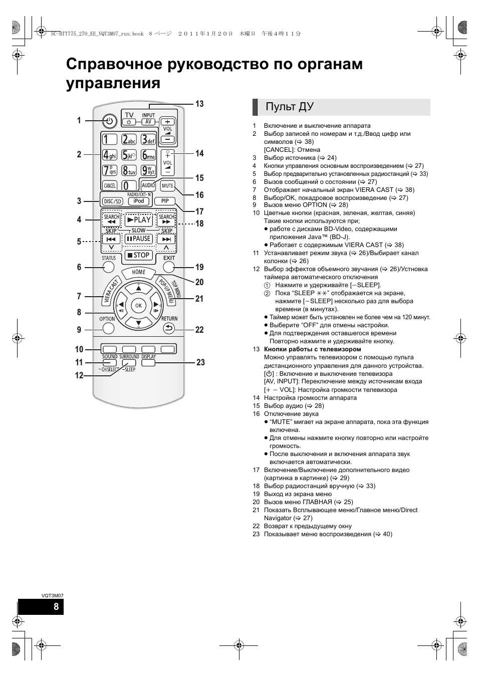
Справочное руководство по органам
управления
1
Включение и выключение аппарата
2
Выбор записей по номерам и т.д./Ввод цифр или
символов (> 38)
[CANCEL]: Отмена
3
Выбор источника (> 24)
4
Кнопки управления основным воспроизведением (> 27)
5
Выбор предварительно установленных радиостанций (> 33)
6
Вызов сообщений о состоянии (> 27)
7
Отображает начальный экран VIERA CAST (> 38)
8
Выбор/OK, покадровое воспроизведение (> 27)
9
Вызов меню OPTION (> 28)
10 Цветные кнопки (красная, зеленая, желтая, синяя)
Такие кнопки используются при;
≥ работе с дисками BD-Video, содержащими
приложения Java™ (BD-J).
≥ Работает с содержимым VIERA CAST (> 38)
11 Устанавливает режим звука (> 26)/Выбирает канал
колонки (> 26)
12 Выбор эффектов объемного звучания (> 26)/Устновка
таймера автоматического отключения
1 Нажмите и удерживайте [
jSLEEP].
2 Пока “SLEEP
££” отображается на экране,
нажмите [jSLEEP] несколько раз для выбора
времени (в минутах).
≥ Таймер может быть установлен не более чем на 120 минут.
≥ Выберите “OFF” для отмены настройки.
≥ Для подтверждения оставшегося времени
Повторно нажмите и удерживайте кнопку.
13 Кнопки работы с телевизором
Можно управлять телевизором с помощью пульта
дистанционного управления для данного устройства.
[Í] : Включение и выключение телевизора
[AV, INPUT]: Переключение между источникам входа
[i j VOL]: Настройка громкости телевизора
14 Настройка громкости аппарата
15 Выбор аудио (> 28)
16 Отключение звука
≥ “MUTE” мигает на экране аппарата, пока эта функция
включена.
≥ Для отмены нажмите кнопку повторно или настройте
громкость.
≥ После выключения и включения аппарата звук
включается автоматически.
17 Включение/Выключение дополнительного видео
(картинка в картинке) (> 29)
18 Выбор радиостанций вручную (> 33)
19 Выход из экрана меню
20 Вызов меню ГЛАВНАЯ (> 25)
21 Показать Всплывающее меню/Главное меню/Direct
Navigator (> 27)
22 Возврат к предыдущему окну
23 Показывает меню воспроизведения (> 40)
ラヰヮユ
モヷ
ンユヵヶンワ
ヴレリヱ
ヱロモヺ
ヱモヶヴユ
ヴヵヰヱ
ヴユモンヤラ
ヴユモンヤラ
ヴロヰヸ
ヴレリヱ
リワヱヶヵ
ユヹリヵ
ㄊヱㄐㄅ
ュリヴヤ
ヱヰ
ヱノヶ
ヱチヮ
ユワ
ヶ
ヷ
リユ
ン
モ
チヤ
モヴ
ヵ
ㄊヱㄐㄅ
ヱリヱ
モヶュリヰ
ヵヰ
ヱチヮ
ユワ
ヶ
19
8
21
13
20
1
4
18
14
16
2
3
6
7
9
10
11
12
22
17
15
5
23
Пульт ДУ
SC-BTT775_270_EE_VQT3M07_rus.book 8 ページ 2011年1月20日 木曜日 午後4時11分
Перед эксплуата-
цией
9
VQT3M07
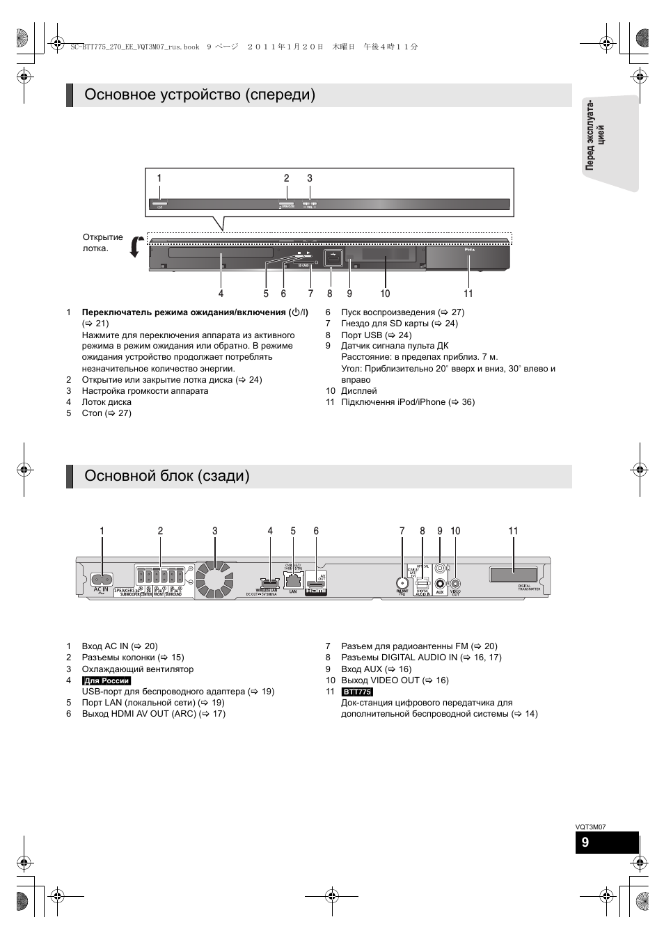
1
Переключатель режима ожидания/включения (Í/I)
(> 21)
Нажмите для переключения аппарата из активного
режима в режим ожидания или обратно. В режиме
ожидания устройство продолжает потреблять
незначительное количество энергии.
2
Открытие или закрытие лотка диска (> 24)
3
Настройка громкости аппарата
4
Лоток диска
5
Стоп (> 27)
6
Пуск воспроизведения (> 27)
7
Гнездо для SD карты (> 24)
8
Порт USB (> 24)
9
Датчик сигнала пульта ДК
Расстояние: в пределах приблиз. 7 м.
Угол: Приблизительно 20e вверх и вниз, 30e влево и
вправо
10 Дисплей
11 Підключення iPod/iPhone (> 36)
1
Вход AC IN (> 20)
2
Разъемы колонки (> 15)
3
Охлаждающий вентилятор
4
[Ljr]Poccnn]
USB-порт для беспроводного адаптера (> 19)
5
Порт LAN (локальной сети) (> 19)
6
Выход HDMI AV OUT (ARC) (> 17)
7
Разъем для радиоантенны FM (> 20)
8
Разъемы DIGITAL AUDIO IN (> 16, 17)
9
Вход AUX (> 16)
10 Выход VIDEO OUT (> 16)
11 [BTT775]
Док-станция цифрового передатчика для
дополнительной беспроводной системы (> 14)
Основное устройство (спереди)
SD CARD
iPod
VOL
OPEN/CLOSE
1
2
3
4
5
7
6
11
9
10
8
Открытие
лотка.
Ocнoвнoй блoк (сзади)
SUBWOOFER
3
6
5
2
1
4
3
3
3
R
L
R
L
Ω
Ω
Ω
Ω
3
Ω
75
CENTER
SURROUND
FRONT
LAN
AUX
FM ANT
WIRELESS LAN
1
2
3
4
5
6
9 10
11
7
8
SC-BTT775_270_EE_VQT3M07_rus.book 9 ページ 2011年1月20日 木曜日 午後4時11分
10
VQT3M07
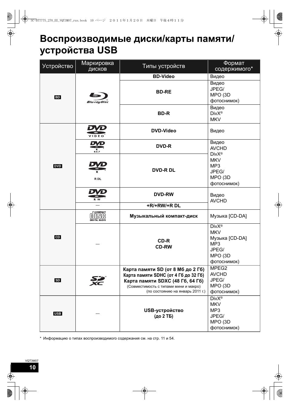
Воспроизводимые диски/карты памяти/
устройства USB
* Информацию о типах воспроизводимого содержания см. на стр. 11 и 54.
Устройство
Маркировка
дисков
Типы устройств
Формат
содержимого*
[BD]
BD-Video
Видео
BD-RE
Видео
JPEG/
MPO (3D
фотоснимок)
BD-R
Видео
DivX
®
MKV
[DVD]
DVD-Video
Видео
DVD-R
Видео
AVCHD
DivX
®
MKV
MP3
JPEG/
MPO (3D
фотоснимок)
DVD-R DL
DVD-RW
Видео
AVCHD
—
+R/+RW/+R DL
[CD]
Музыкальный компакт-диск
Музыка [CD-DA]
—
CD-R
CD-RW
DivX
®
MKV
Музыка [CD-DA]
MP3
JPEG/
MPO (3D
фотоснимок)
[SD]
Карта памяти SD (от 8 Мб до 2 Гб)
Карта памяти SDHC (от 4 Гб до 32 Гб)
Карта памяти SDXC (48 Гб, 64 Гб)
(Совместимость с типами мини и макро)
(по состоянию на январь 2011 г.)
MPEG2
AVCHD
JPEG/
MPO (3D
фотоснимок)
[USB]
—
USB-устройство
(до 2 TБ)
DivX
®
MKV
MP3
JPEG/
MPO (3D
фотоснимок)
SC-BTT775_270_EE_VQT3M07_rus.book 10 ページ 2011年1月20日 木曜日 午後4時11分
10:32
Panasonic SC-PT480PC-K review & setup!
10:21
Panasonic SC-BTT270(SCBTT270EBK)Video Review Bluray Home Ci
01:21
Panasonic SC-BTT270 3D Blu-ray Home Cinema
03:11
SC-BTT270 — Full HD 3D Blu-ray система домашнего кинотеатра Panasonic .wmv
08:16
Panasonic SC-BTT195 3D Blu-Ray Disc 5.1 Surround Sound Home Theater System
09:24
Panasonic SC-BTT465EG9
00:44
Full HD 3D Blu-ray система домашнего кинотеатра Panasonic SC-BTT270
Нажмите на кнопку для помощи
Table of Contents
- [Panasonic SC-BTT / SA-BTT Series Manual BTT770,BTT730,BTT270,BTT273
- Read User Manual Online (PDF format)
- Download This Manual (PDF format)
Panasonic SC-BTT / SA-BTT Series Manual [BTT770,BTT730,BTT270,BTT273
Owner’s Manual
Blu-ray DiscTM Home Theater Sound System
Dear customer
Thank you for purchasing this product.
For optimum performance and safety, please read these instructions carefully.
Before connecting, operating or adjusting this product, please read the
instructions completely.
Please keep this manual for future reference.
If you have any questions contact
U.S.A. and Puerto Rico : 1-800-211-PANA(7262)
Canada : 1-800-561-5505
THE FOLLOWING APPLIES ONLY IN THE U.S.A.
FCC Note:
This equipment has been tested and found to comply with the limits for a
Class B digital device, pursuant to Part 15 of the FCC Rules.
These limits are designed to provide reasonable protection against
harmful interference in a residential installation. This equipment
generates, uses, and can radiate radio frequency energy and, if not
installed and used in accordance with the instructions, may cause harmful
interference to radio communications.
However, there is no guarantee that interference will not occur in a
particular installation. If this equipment does cause harmful interference to
radio or television reception, which can be determined by turning the
equipment off and on, the user is encouraged to try to correct the
interference by one or more of the following measures:
≥ Reorient or relocate the receiving antenna.
≥ Increase the separation between the equipment and receiver.
≥ Connect the equipment into an outlet on a circuit different from that to
which the receiver is connected.
≥ Consult the dealer or an experienced radio/TV technician for help.
FCC Caution:To assure continued compliance, follow the attached
installation instructions and use only shielded interface cables when
connecting to peripheral devices. Any changes or modifications not
expressly approved by the party responsible for compliance could void the
user’s authority to operate this equipment.
This device complies with Part 15 of the FCC Rules.
Operation is subject to the following two conditions:
(1) This device may not cause harmful interference, and
(2) this device must accept any interference received, including
interference that may cause undesired operation.
Responsible Party:
Panasonic Corporation of North America
One Panasonic Way
Secaucus, NJ 07094
Support Contact:
Panasonic Consumer Electronics Company
Telephone No.: 1-800-211-PANA (7262)
THE FOLLOWING APPLIES IN THE U.S.A. AND CANADA
This device complies with Part 15 of FCC Rules and RSS-Gen of IC Rules.
Operation is subject to the following two conditions:
(1) This device may not cause interference, and (2) this device must accept
any interference, including interference that may cause undesired operation
of this device.
Contains FCC ID: RYYWYPAEBUX4
Contains IC:4389B-WYPAEBUX4
This transmitter must not be co-located or operated in conjunction with any
other antenna or transmitter.
This product is restricted to indoor use due to its operation in the 5.15 to
5.25 GHz frequency range.
FCC and IC require this product to be used indoors for the frequency range
5.15 to 5.25 GHz to reduce the potential for harmful interference to
co-channel Mobile Satellite systems. High power radars are allocated as
primary users of the 5.25 to 5.35 GHz and 5.65 to 5.85 GHz bands. These
radar stations can cause interference with and/or damage this product.
This equipment complies with FCC/IC radiation exposure limits set forth for
an uncontrolled environment and meets the FCC radio frequency (RF)
Exposure Guidelines in Supplement C to OET65 and RSS-102 of the IC
radio frequency (RF) Exposure rules. This equipment has very low levels of
RF energy that it deemed to comply without maximum permissive exposure
evaluation (MPE). But it is desirable that it should be installed and operated
keeping the radiator at least 20cm or more away from person’s body
(excluding extremities: hands, wrists, feet and ankles).
[BTT770]
THE FOLLOWING APPLIES ONLY IN THE U.S.A.
FCC Note:
This equipment has been tested and found to comply with the limits for a
Class B digital device, pursuant to Part 15 of the FCC Rules.
These limits are designed to provide reasonable protection against
harmful interference in a residential installation. This equipment
generates, uses and can radiate radio frequency energy and, if not
installed and used in accordance with the instructions, may cause harmful
interference to radio communications.
However, there is no guarantee that interference will not occur in a
particular installation. If this equipment does cause harmful interference to
radio or television reception, which can be determined by turning the
equipment off and on, the user is encouraged to try to correct the
interference by one or more of the following measures:
≥ Reorient or relocate the receiving antenna.
≥ Increase the separation between the equipment and receiver.
≥ Connect the equipment into an outlet on a circuit different from that to
which the receiver is connected.
≥ Consult the dealer or an experienced radio/TV technician for help.
FCC caution: To maintain compliance with FCC regulations, shielded
interface cables must be used with this equipment. Operation with
non-approved equipment or unshielded cables may result in interference
to radio and TV reception. Any changes or modifications not approved by
the party responsible for compliance could void the user’s authority to
operate this equipment.
This device complies with Part 15 of the FCC Rules.
Operation is subject to the following two conditions:
(1) This device may not cause harmful interference, and
(2) this device must accept any interference received, including
interference that may cause undesired operation.
Responsible Party:
Panasonic Corporation of North America
One Panasonic Way, Secaucus, NJ 07094
Support Contact:
Panasonic Consumer Electronics Company
Telephone No.: 1-800-211-PANA (7262)
WARNING:
To satisfy FCC RF exposure requirements for mobile transmitting devices,
a separation distance of 20 cm or more should be maintained between the
antenna of this device and persons during device operation.
To ensure compliance, operations at closer than this distance is not
recommended. The antenna used for this transmitter must not be
co-located in conjunction with any other antenna or transmitter.
[BTT770]
THE FOLLOWING APPLIES ONLY IN CANADA.
This Class B digital apparatus complies with Canadian ICES-003.
[BTT770] [BTT370]
THE FOLLOWING APPLIES ONLY IN CANADA.
For main unit
Product Identification Marking is located on the bottom of the unit.
[BTT770]
For wireless system
Product Identification Marking is located on the bottom of wireless system.
IMPORTANT SAFETY
INSTRUCTIONS
Read these operating instructions carefully before using the unit. Follow the
safety instructions on the unit and the applicable safety instructions listed
below. Keep these operating instructions handy for future reference.
1 Read these instructions.
2 Keep these instructions.
3 Heed all warnings.
4 Follow all instructions.
5 Do not use this apparatus near water.
6 Clean only with dry cloth.
7 Do not block any ventilation openings. Install in accordance with the
manufacturer’s instructions.
8 Do not install near any heat sources such as radiators, heat registers,
stoves, or other apparatus (including amplifiers) that produce heat.
9 Do not defeat the safety purpose of the polarized or grounding-type plug.
A polarized plug has two blades with one wider than the other.
A grounding-type plug has two blades and a third grounding prong. The
wide blade or the third prong are provided for your safety. If the provided
plug does not fit into your outlet, consult an electrician for replacement of
the obsolete outlet.
10 Protect the power cord from being walked on or pinched particularly at
plugs, convenience receptacles, and the point where they exit from the
apparatus.
11 Only use attachments/accessories specified by the manufacturer.
12 Use only with the cart, stand, tripod, bracket, or table
specified by the manufacturer, or sold with the
apparatus. When a cart is used, use caution when
moving the cart/apparatus combination to avoid injury from tip-over.
13 Unplug this apparatus during lightning storms or when unused for long
periods of time.
14 Refer all servicing to qualified service personnel. Servicing is required
when the apparatus has been damaged in any way, such as
power-supply cord or plug is damaged, liquid has been spilled or objects
have fallen into the apparatus, the apparatus has been exposed to rain
or moisture, does not operate normally, or has been dropped.
WARNING
Unit
To reduce the risk of fire, electric shock or product damage,
– Do not expose this unit to rain, moisture, dripping or splashing.
– Do not place objects filled with liquids, such as vases, on this unit.
– Use only the recommended accessories.
– Do not remove covers.
– Do not repair this unit by yourself. Refer servicing to qualified service
personnel.
CAUTION
Unit
– This unit utilizes a laser. Use of controls or adjustments or performance of
procedures other than those specified herein may result in hazardous
radiation exposure.
– Do not place sources of naked flames, such as lighted candles, on this unit.
Placement
To reduce the risk of fire, electric shock or product damage,
– Do not install or place this unit in a bookcase, built-in cabinet or in
another
confined space. Ensure this unit is well ventilated.
– Do not obstruct this unit’s ventilation openings with newspapers,
tablecloths, curtains, and similar items
This Owner’s Manual is applicable to models
SC-BTT770, SC-BTT370, SC-BTT270 and SC-BTT273.
Unless otherwise indicated, illustrations in this Owner’s
Manual are of SC-BTT770.
≥ Operations in this Owner’s Manual are described mainly
with the remote control, but you can perform the
operations on the main unit if the controls are the same.
Indicates features applicable to:
[BTT770]: SC-BTT770 only
[BTT370]: SC-BTT370 only
[BTT270]: SC-BTT270 only
[BTT273]: SC-BTT273 only
System SC-BTT770 SC-BTT370 SC-BTT270 SC-BTT273
Main unit SA-BTT770 SA-BTT370 SA-BTT270 SA-BTT273
Speaker system Front speakers SB-HF775 SB-HF370 SB-HF270 SB-HF370
Center speaker SB-HC775 SB-HC370 SB-HC270 SB-HC370
Surround speakers SB-HS270 SB-HS270 SB-HS270 SB-HS270
Subwoofer SB-HW370 SB-HW370 SB-HW270 SB-HW270
Wireless system (with digital transmitter) SH-FX71
≥ Some accessories and external devices mentioned in this Owner’s Manual that
are not included with this product may not be on sale in certain regions.
≥ Please note that the actual controls and components, menu items, etc. of
your Blu-ray Disc Home Theater Sound System may look somewhat different from
those shown in the illustrations in this Owner’s Manual.
Accessory
Check the supplied accessories before using this unit.
For accessories of speakers, refer to page 10.
Control reference guide
Remote control
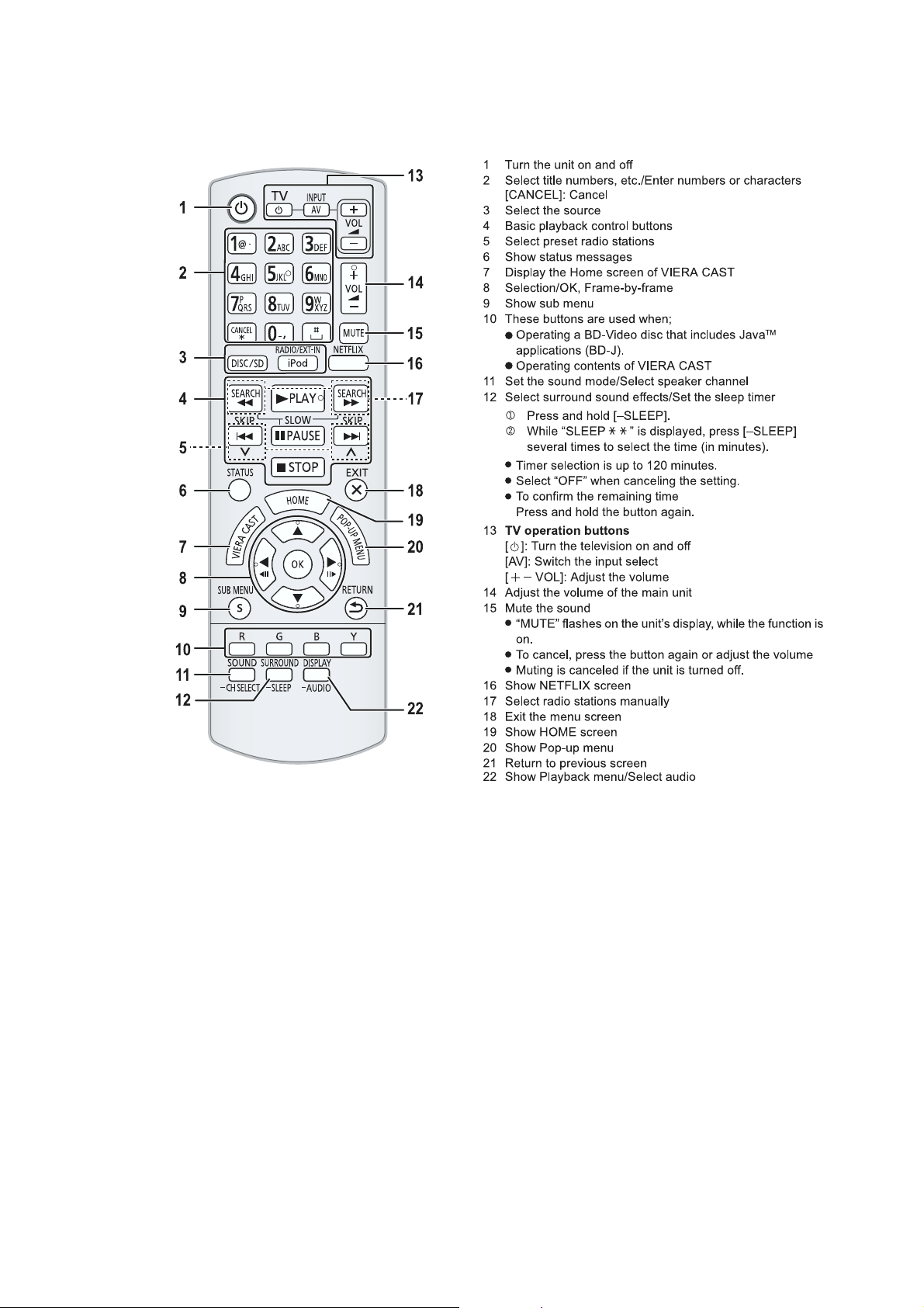
1 Turn the unit on and off
2 Select title numbers, etc./Enter numbers or characters
(? 34)
3 Select the source (? 22)
4 Basic playback control buttons (? 25)
5 Select preset radio stations
6 Show status messages (? 25)
7 Display the Home screen of VIERA CAST (? 34)
8 Selection/OK, Frame-by-frame (? 25)
9 Show sub menu (? 26)
10 These buttons are used when;
≥ Operating a BD-Video disc that includes JavaTM
applications (BD-J).
≥ Operating contents of VIERA CAST (? 34)
11 Set the sound mode (? 24)/Select speaker channel
(? 24)
12 Select surround sound effects (? 24)/Set the sleep timer
1 Press and hold [–SLEEP].
2 While “SLEEP ££” is displayed, press [–SLEEP] several times to select the
time (in minutes).
≥ Timer selection is up to 120 minutes.
≥ Select “OFF” when canceling the setting.
≥ To confirm the remaining time
Press and hold the button again.
13 TV operation buttons
[Í]: Turn the television on and off
[AV, INPUT]: Switch the input select
[i j VOL]: Adjust the volume
14 Adjust the volume of the main unit
15 Mute the sound
≥ “MUTE” flashes on the unit’s display, while the function is
on.
≥ To cancel, press the button again or adjust the volume.
≥ Muting is canceled if the unit is turned off.
16 Show NETFLIX screen
17 Select radio stations manually (? 29)
18 Exit the menu screen
19 Show HOME menu (? 23)
20 Show Pop-up menu/Top menu/Direct Navigator (? 25)
21 Return to previous screen
22 [BTT770] [BTT370] : Start up a video communication (? 34)
23 Show Playback menu (? 35)/Select audio (? 25)
Main unit (Front)
1 Standby/on switch (POWER Í/I) (? 19)
Press to switch the unit from on to standby mode or vice
versa. In standby mode, the unit is still consuming a small
amount of power.
2 Open or close the disc tray (? 22)
3 Adjust the volume of the main unit
4 Disc tray
5 Stop (? 25)
6 Start play (? 25)
7 SD card slot (? 22)
8 Remote control signal sensor
Distance: Within approx. 7 m (23 ft.)
Angle: Approx. 20o up and down, 30o left and right
9 Display
10 Connect iPod/iPhone (? 32)
POWER-SAVING FEATURES
The main unit is designed to conserve its power consumption and save energy.
[BTT770] [BTT370] Wireless system (SH-FX71) does not have this function.
≥ Automatic power-down function
The main unit will automatically switch to standby mode after
30 minutes if the main unit is inactive as follows.
e.g.
jThere is no audio signal from an external device.
jDisc playback is stopped/paused.
jiPod/iPhone playback is stopped/paused.
jThe disc menu is displayed and play is not selected.
(This function may not work depending on the application
type of discs.)
1 AC IN terminal (? 18)
2 Speaker terminals (? 13)
3 Cooling fan
4 [BTT770] [BTT370] USB port for the Communication Camera
TY-CC10W (optional) (? 34)
5 LAN port (? 17)
6 HDMI AV OUT (ARC) terminal (? 15)
7 [BTT770] [BTT370] HDMI 1 IN (CABLE/SAT) terminal (? 16)
8 [BTT770] [BTT370] HDMI 2 IN terminal (? 16)
9 FM radio antenna terminal (? 16)
10 DIGITAL AUDIO IN terminal (? 14 , 15)
11 AUX terminal (? 14)
12 VIDEO OUT terminal (? 14)
13 [BTT770] Digital transmitter dock for supplied wireless
system (? 17)
[BTT370] Digital transmitter dock for optional wireless
system (? 12)
Playable discs/Cards
Discs that cannot be played in this unit
Any other disc that is not specifically supported or
previously described.
1. DVD-RAM
2. Super Audio CD
3. Photo CD
4. DVD-Audio
5. Video CD and Super Video CD
6. WMA discs
7. DivX discs
8. PAL discs
9. HD DVD
10 BD-Video discs recorded at a rate of 50 fields/sec
Region management information
BD-Video
This unit plays BD-Video marked with labels containing the
region code “A”.
Example:
DVD-Video
This unit plays DVD-Video marked with labels containing the
region number “1” or “ALL”.
Example:
Finalize
DVD-R/RW/R DL, +R/+RW/+R DL and CD-R/RW recorded by
a recorder, etc. needs to be finalized by the recorder to play on
this unit. Please refer to the recorder’s instructions.
BD-Video
This unit supports high bit rate audio (Dolby Digital Plus, Dolby
TrueHD, DTS-HD High Resolution Audio and DTS-HD Master
Audio) adopted in BD-Video.
Music CD
≥ Operation and sound quality of CDs that do not conform to
CD-DA specifications (copy control CDs, etc.) cannot be
guaranteed.
≥ The digital audio content side of a DualDisc does not meet
the technical specifications of the Compact Disc Digital
Audio (CD-DA) format so playback may not be possible.
3D
≥ 3D videos and 3D still pictures can be played back when this
unit is connected to a 3D compatible TV using a High Speed
HDMI Cable.
≥ 2D video can be enjoyed as 3D virtually. (? 27)
Unit and media care
Using the remote control
Questions about your panasonic SC-BTT / SA-BTT Series Manual
[BTT770,BTT730,BTT270,BTT273]? Post in the comments!
Download panasonic SC-BTT / SA-BTT Series Manual
[BTT770,BTT730,BTT270,BTT273]Manual [PDF]
Read User Manual Online (PDF format)
Read User Manual Online (PDF format) >>
Download This Manual (PDF format)
Download this manual >>

PSG1101004CE
A6
Blu-ray DiscTM Home Theater Sound System
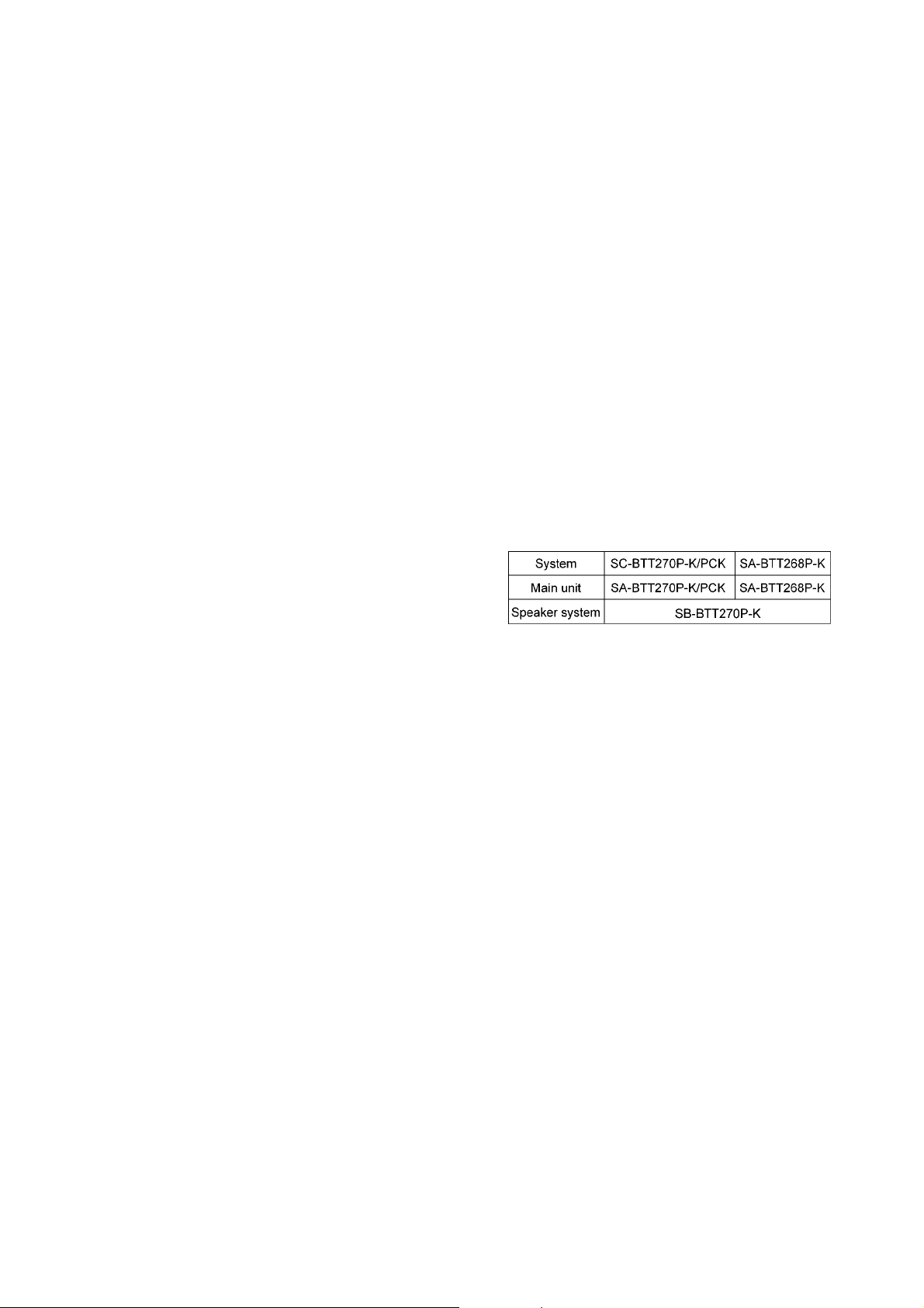
Model No. SA-BTT270P
SA-BTT270PC
SA-BTT268P
Vol.1
Product Color: (K)…Black Type
Notes: Please refer to the original service manual for:
• Speaker system SB-BTT270P-K/PCK, Order No: PSG1101003CE.
TABLE OF CONTENTS
PAGE PAGE
1 Safety Precautions———————————————— 3
1.1. GENERAL GUIDELINES——————————— 3
1.2. Before Repair and Adjustment————————-3
1.3. Protection Circuitry—————————————- 4
1.4. Safety Parts Information———————————4
2 Warning————————————————————— 5
2.1. Prevention of Electrostatic Discharge (ESD)
to Electrostatic Sensitive (ES) Devices ————— 5
2.2. Precaution of Laser Diode——————————- 6
2.3. Service caution based on Legal restrictions———7
3 Service Navigation ————————————————9
4 Specifications—————————————————- 13
2.4. Handling Precaution for Traverse Unit—————-7
3.1. Service Information—————————————-9
3.2. Combination of Multiple Pressing on the
Remote Control———————————————9
3.3. Entering Special Modes with Combination of
Multiple Pressing on the Remote Control————9
3.4. Caution for Replacing Parts————————— 11
4.1. Others (Licenses)—————————————-14
© Panasonic Corporation 2011. All rights reserved.
Unauthorized copying and distribution is a violation
of law.

5 Location of Controls and Components——————15
5.1. Remote Control Key Button Operations————15
5.2. Main Unit Key Button Operations ———————16
5.3. Speaker Connection————————————-16
5.4. Power Saving Features———————————17
5.5. Connection to a Broadband Network —————18
5.6. Network Easy Setting————————————19
5.7. Firmware Updates —————————————21
5.8. Enjoying BD-LIVE or Picture-in-picture in BDVideo ———————————————————22
5.9. Enjoying 3D Video —————————————23
5.10. Using the iPod/iPhone ———————————-24
5.1 1 . Enjoying VIERA CAST™——————————-26
5.12. Playable discs/Cards————————————27
5.13. File Extension Type Support (MP3/JPEG)———28
6 Operating Instructions—————————————-29
6.1. Removing of disc during abnormality —————29
7 Self-Diagnostic and Special Mode Setting ————-31
7.1. Special Mode Setting————————————31
7.2. Self-Diagnostic Function — Error Code————— 35
7.3. Service Mode———————————————-38
8 Troubleshooting Guide—————————————-45
8.1. Troubleshooting Guide for F61 and/or F76——— 45
9 Service Fixture & Tools—————————————48
9.1. Service Tools and Equipment————————-48
10 Disassembly and Assembly Instructions—————49
10.1. Disassembly Flow Chart———————————50
10.2. Main Components and P.C.B. Locations————51
10.3. Disassembly of Top Cabinet—————————52
10.4. Disassembly of Rear Panel—————————-53
10.5. Disassembly of Fan—————————————54
10.6. Disassembly of Front Panel Assembly ————-54
10.7. Disassembly of WI-FI P.C.B. (For SA-BTT270
Only)———————————————————55
10.8. Disassembly of Panel P.C.B.—————————56
10.9. Disassembly of Operation Button P.C.B.———— 57
10.10. Disassembly of Power Button P.C.B.—————-58
10.11. Disassembly of iPod Cradle Assembly————-59
10.12. Disassembly of iPod P.C.B.—————————-60
10.13. Replacement of Front Lid Assembly —————-61
10.14. Disassembly of BD Mechanism Unit (BRS1P) —63
10.15. Disassembly of AC Inlet P.C.B.————————86
10.16. Disassembly of D-Amp P.C.B.————————87
10.17. Replacement of Digital Amplifier IC (IC5100/
IC5200/IC5300)——————————————-89
10.18. Disassembly of Digital P.CB.—————————91
10.19. Disassembly of AV P.C.B.——————————94
10.20. Disassembly of SMPS P.C.B.————————-95
10.21. Replacement of Switching Regulator IC
(IC5701) —————————————————-97
10.22. Replacement of Rectifier Diode (D5702)————99
10.23. Replacement of Thermal Diode (D5802)——— 101
10.24. Replacement of Regulator Diode (D5803)——- 102
11 Service Position ———————————————— 104
11.1. Checking & Repairing of Digital P.C.B. ———— 104
11.2. Checking & Repairing D-Amp P.C.B.————— 105
11.3. Checking & Repairing SMPS P.C.B. ————— 107
11.4. Checking & Repairing Panel P.C.B. ————— 108
11.5. Checking & Repairing of AV P.C.B.—————- 108
12 Voltage & Waveform Chart——————————— 110
12.1. Digital P.C.B. (1/2) —————————————110
12.2. Digital P.C.B. (2/2)————————————— 111
12.3. A V P.C.B. ————————————————-112
12.4. Panel P.C.B. ———————————————112
12.5. D-Amp P.C.B. (1/2)————————————- 113
12.6. D-Amp P.C.B. (2/2)————————————- 114
12.7. SMPS P.C.B.———————————————115
12.8. Waveform Table (1/2)———————————-116
12.9. Waveform Table (2/2)———————————-117
13 Illustration of ICs, Transistor and Diode—————118
14 Simplified Block Diagram————————————119
15 Block Diagram—————————————————120
15.1. System Control——————————————120
15.2. Audio & Video ——————————————-121
15.3. Power Supply(Main Section) ————————123
16 Wiring Connection Diagram ——————————-125
17 Schematic Diagram——————————————-127
17.1. Schematic Diagram Notes —————————127
17.2. Digital(Micon/Power) Circuit ————————-129
17.3. A V Circuit ————————————————-136
17.4. D-Amp Circuit———————————————137
17.5. Panel Circuit ———————————————141
17.6. Power Button, Operation Button & iPod Circuit -142
17.7. SMPS Circuit———————————————143
17.8. AC Inlet Circuit ——————————————145
18 Printed Circuit Board——————————————146
18.1. Digital P.C.B.———————————————146
18.2. AV, Panel, Power Button, Operation Button &
iPod P.C.B. ————————————————148
18.3. D-Amp P.C.B.———————————————149
18.4. SMPS & AC Inlet P.C.B. ——————————150
19 Terminal Function of ICs————————————151
19.1. IC6001(C0HBB0000057): IC FL Driver————151
20 Exploded View and Replacement Parts List———-153
20.1. Exploded View and Mechanical replacement
Part List —————————————————153
20.2. Electrical Replacement Part List———————159
2
1 Safety Precautions
1.1. GENERAL GUIDELINES
1. When servicing, observe the original lead dress. If a short circuit is found, replace all parts which have been overheated or
damaged by the short circuit.
2. After servicing, see to it that all the protective devices such as insulation barriers, insulation papers shields are properly
installed.
3. After servicing, carry out the following leakage current checks to prevent the customer from being exposed to shock hazards.
1.1.1. LEAKAGE CURRENT COLD CHECK
1. Unplug the AC cord and connect a jumper between the two prongs on the plug.
2. Measure the resistance value, with an ohmmeter, between the jumpered AC plug and each exposed metallic cabinet part on
the equipment such as screwheads, connectors, control shafts, etc. When the exposed metallic part has a return path to the
chassis, the reading should be between 1MΩ and 5.2MΩ.
When the exposed metal does not have a return path to the chassis, the reading must be
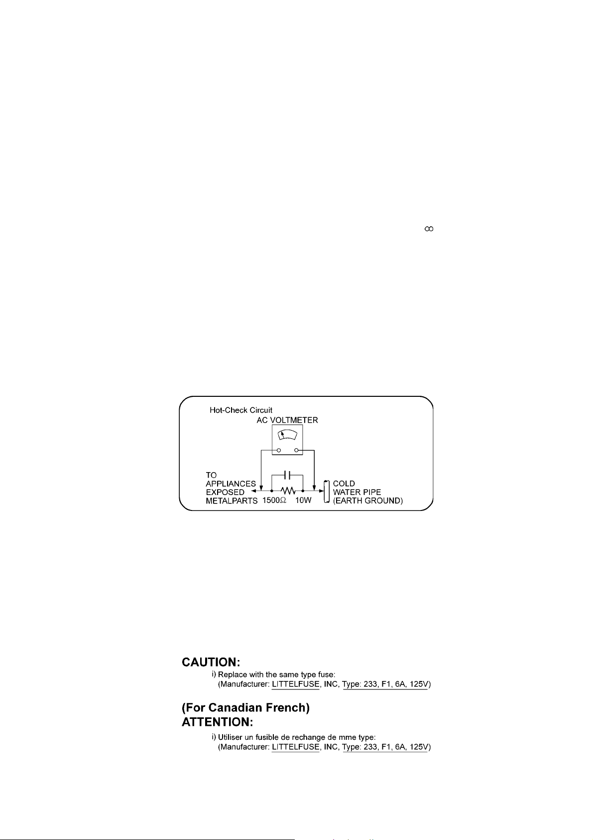
1.1.2. LEAKAGE CURRENT HOT CHECK
1. Plug the AC cord directly into the AC outlet. Do not use an isolation transformer for this check.
2. Connect a 1.5kΩ, 10 watts resistor, in parallel with a 0.15µF capacitors, between each exposed metallic part on the set and a
good earth ground such as a water pipe, as shown in Figure 1.
3. Use an AC voltmeter, with 1000 ohms/volt or more sensitivity, to measure the potential across the resistor.
4. Check each exposed metallic part, and measure the voltage at each point.
5. Reverse the AC plug in the AC outlet and repeat each of the above measurements.
6. The potential at any point should not exceed 0.75 volts RMS. A leakage current tester (Simpson Model 229 or equiva lent)
may be used to make the hot checks, leakage current must not exceed 1/2 milliamp. In case a measurement is outside of the
limits specified, there is a possibility of a shock hazard, and the equipment should be repaired and rechecked before it is
returned to the customer.
Figure 1
1.2. Before Repair and Adjustment
Disconnect AC power to discharge unit AC Capacitors as such (C5700, C5701, C5702, C5704, C5705, C5706) through a 10 Ω, 10
W resistor to ground.
Caution:
DO NOT SHORT-CIRCUIT DIRECTLY (with a screwdriver blade, for instance), as this may destroy solid state devices.
After repairs are completed, restore power gradually using a variac, to avoid overcurrent.
Current consumption at AC 120 V, 60 Hz in NO SIGNAL mode at volume minimum should be ~ 600 mA.
1.2.1. Caution for fuse replacement
3

1.3. Protection Circuitry
The protection circuitry may have operated if either of the following conditions are noticed:
• No sound is heard when the power is turned on.
• Sound stops during a performance.
The function of this circuitry is to prevent circuitry damage if, for example, the positive and negative speaker connection wires are
“shorted”, or if speaker systems with an impedance less than the indicated rated impedance of the amplifier are used.
If this occurs, follow the procedure outlines below:
1. Turn off the power.
2. Determine the cause of the problem and correct it.
3. Turn on the power once again after one minute.
Note:
When the protection circuitry functions, the unit will not operate unless the power is first turned off and then on again.
1.4. Safety Parts Information
Safety Parts List:
There are special components used in this equipment which are important for safety.
These parts are marked by ( ) in the Schematic Diagrams & Replacement Parts List. It is essential that these critical parts
should be replaced with manufacturer’s specified parts to prevent shock, fire or other hazards. Do not modify the original design
without permission of manufacturer.
Safety Ref No. Part No. Part Name & Description Remarks
10 REXX1186 1P RED WIRE (AC INLET-SMPS)
11 REXX1187 1P BLACK WIRE (AC INLET-SMPS)
19 RGRX1006E-B1 REAR PANEL BTT270P
19 RGRX1006E-C2 REAR PANEL BTT270PC
19 RGRX1006E-D REAR PANEL BTT268P
29 RKMX1010-K TOP CABINET
29-1 RMNX1062 SMPS PCB TOP INSULATOR
54 RXQX1056 SMPS PC SHEET UNIT
55 RXQX1057 AC IN PC SHEET UNIT
60 VXY2122T BD MECHANISM
101 VQL1V70-J LASER CAUTION LABEL
A2 K2CB2CB00021 AC CORD
A3 VQT3D27-1 O/I BOOK (En) BTT270P
A3 VQT3D28-1 O/I BOOK (Cf) BTT270PC
A3 VQT3M40-1 O/I BOOK (En) BTT268P
PCB6 REP4699E AC INLET P.C.B (RTL)
PCB7 REP4699E SMPS P.C.B. (RTL)
PCB9 RFKB4689A DIGITAL P.C.B. ASS’Y JIG & ADJ, (ESD)
DZ5701 ERZV10V511CS ZNR
L5701 ELF19H520E INDUCTOR
L5702 ELF19H520E INDUCTOR
T5701 ETS61BA11GBD TRANSFORMER
T5751 ETS19AB2E6AG SUB TRANSFORMER
T6100 G4D1A0000142 SWITCHING TRANSFORMER
PC5702 B3PBA0000503 PHOTO COUPLER
PC5720 B3PBA0000503 PHOTO COUPLER
PC5799 B3PBA0000503 PHOTO COUPLER
PC5901 B3PBA0000503 PHOTO COUPLER
F1 K5D602APA008 FUSE
TH5702 D4CAA2R20001 THERMISTOR
P5701 K2AB2B000007 AC INLET
C5700 F1BAF1020020 1000pF
C5701 F0CAF104A105 0.1uF
C5702 F0CAF104A105 0.1uF
C5704 F1BAF1020020 1000pF
C5705 F1BAF1020020 1000pF
C5706 F1BAF471A013 470pF
4

2Warning
2.1. Prevention of Electrostatic Discharge (ESD) to Electrostatic Sensitive
(ES) Devices
Some semiconductor (solid state) devices can be damaged easily by static electricity. Such components commonly are called Electrostatically Sensitive (ES) Devices. Examples of typical ES devices are integrated circuits and some field-effect transistors and
semiconductor “chip” components. The following techniques should be used to help reduce the incidence of component damag e
caused by electrostatic discharge (ESD).
1. Immediately before handling any semiconductor component or semiconductor-equipped assembly, drain off any ESD on your
body by touching a known earth ground. Alternatively, obtain and wear a commercially available discharging ESD wrist strap,
which should be removed for potential shock reasons prior to applying power to the unit under test.
2. After removing an electrical assembly equipped with ES devices, place the assembly on a conductive surface such as al uminum foil, to prevent electrostatic charge buildup or exposure of the assembly.
3. Use only a grounded-tip soldering iron to solder or unsolder ES devices.
4. Use only an anti-static solder removal device. Some solder removal devices not classified as “anti-static (ESD protected)” can
generate electrical charge sufficient to damage ES devices.
5. Do not use freon-propelled chemicals. These can generate electrical charges sufficient to damage ES devices.
6. Do not remove a replacement ES device from its protective package until immediately before you are ready to install it. (Most
replacement ES devices are packaged with leads electrically shorted together by conductive foam, aluminum foil or comparable conductive material).
7. Immediately before removing the protective material from the leads of a replacement ES device, touch the protective material
to the chassis or circuit assembly into which the device will be installed.
Caution:
Be sure no power is applied to the chassis or circuit, and observe all other safety precautions.
8. Minimize bodily motions when handling unpackaged replacement ES devices. (Otherwise harmless motion such as the
brushing together of your clothes fabric or the lifting of your foot from a carpeted floor can generate static electricity (ESD) sufficient to damage an ES device).
5
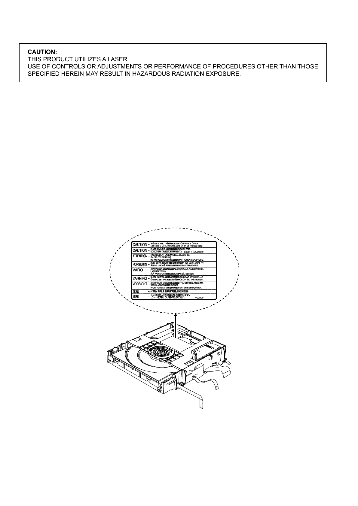
2.2. Precaution of Laser Diode
Caution:
This product utilizes a laser diode with the unit turned “on”, invisible laser radiation is emitted from the pickup lens.
Wavelength: 790 nm (CDs), 655 nm (DVDs), 405 nm (BDs)
Maximum output radiation power from pick up : 10 0 µW/VDE
Laser radiation from the pickup unit is safety level, but be sure the followings:
1. Do not disassemble the pickup unit, since radiation from exposed laser diode is dangerous.
2. Do not adjust the variable resistor on the pickup unit. It was already adjusted.
3. Do not look at the focus lens using optical instruments.
4. Recommend not to look at pickup lens for a long time.
ACHTUNG :
Dieses Produkt enthält eine Laserdiode. Im eingeschalteten Zustand wird unsichtbare Laserstrahlung von der Lasereinheit
adgestrahit.
Wellenlänge: 790 nm (CDs), 655 nm (DVDs), 405 nm (BDs)
Maximale Strahlungsleistung der Lasereinhelt: 100 µW/VDE
Die strahlungan der Lasereinheit ist ungefährlich, wenn folgende Punkte beachtet werden:
1. Die Lasereinheit nicht zerlegen, da die Strahlung an der freigelegten Laserdiode gefährlich ist.
2. Den werksseitig justierten Einstellregler der Lasereinheit nicht verstellen.
3. Nicht mit optischen Instrumenten in die Fokussierlinse blicken.
4. Nicht über längere Zeit in die Fokussierlinse blicken.
6

2.3. Service caution based on Legal restrictions
The lead free solder has been used in the mounting process of all electrical comp onents on the printed circui t boa rds used for this
equipment in considering the globally environmental conservation.
The normal solder is the alloy of tin (Sn) and lead (Pb). On the other hand, the lead free solder is the alloy mainly consists of tin
(Sn), silver (Ag) and Copper (Cu), and the melting point of the lead free solder is higher approx.30 degrees C (86°F) more than that
of the normal solder.
Definition of PCB Lead Free Solder being used
The letter of “PbF” is printed either foil side or components side on the PCB using the lead free solder.
(See right figure)
Service caution for repair work using Lead Free Solder (PbF)
• The lead free solder has to be used when repairing the equipment for which the lead free solder is used.
(Definition: The letter of “PbF” is printed on the PCB using the lead free solder.)
• To put lead free solder, it should be well molten and mixed with the original lead free solder.
• Remove the remaining lead free solder on the PCB cleanly for soldering of the new IC.
• Since the melting point of the lead free solder is higher than that of the normal lead solder, it takes the longer time to melt the
lead free solder.
• Use the soldering iron (more than 70W) equipped with the temperature con trol after setting the temperatu re at 350±30 degrees
C (662±86°F).
Recommended Lead Free Solder (Service Parts Route.)
• The following 3 types of lead free solder are available through the service parts route.
RFKZ03D01K————(0.3mm 100g Reel)
RFKZ06D01K————(0.6mm 100g Reel)
RFKZ10D01K————(1.0mm 100g Reel)
Note
* Ingredient: tin (Sn), 96.5%, silver (Ag) 3.0%, Copper (Cu) 0.5%, Cobalt (Co) / Germanium (Ge) 0.1 to 0.3%
2.4. Handling Precaution for Traverse Unit
The laser diode in the optical pickup unit may break down du e to static electricity of clothes or human body. Special care must be
taken avoid caution to electrostatic breakdown when servicing and handling the laser diode in the traverse unit.
2.4.1. Cautions to Be Taken in Handling the Optical Pickup Unit
The laser diode in the optical pickup unit ma y be damaged due to electrostatic discharge genera ting from clothes or human body.
Special care must be taken avoid caution to electrostatic discharge damage when servicing the laser diode.
1. Do not give a considerable shock to the optical pickup unit as it has an extremely high-precise structure.
2. To prevent the l aser diode from the electrostatic discharge damage, the flexible cable of the optical pickup unit removed
should be short-circuited with a short pin or a clip.
3. The flexible cable may be cut off if an excessive force is applied to it. Use caution when handling the flexible cable.
4. The antistatic FPC is connected to the new optical pickup unit. After replacing the optical pickup unit and connecting the flexi-
7
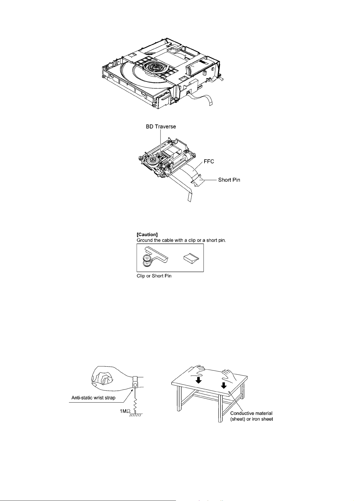
ble cable, cut off the antistatic FPC.
Figure 1
2.4.2. Grounding for electrostatic breakdown prevention
Some devices such as the DVD player use the optical pickup (laser diode) and the optical pickup will be damaged by static electricity in the working environment. Proceed servicing works under the working environment where grounding works is completed.
2.4.2.1. Worktable grounding
1. Put a conductive material (sheet) or iron sheet on the area where the optical pickup is placed, and groun d the sheet.
2.4.2.2. Human body grounding
1. Use the anti-static wrist strap to discharge the static electricity form your body.
Figure 2
8
3 Service Navigation
3.1. Service Information
This service manual contains technical information which will allow service personnel’s to understand and service this model.
Please place orders using the parts list and not the drawing reference numbers.
If the circuit is changed or modified, this information will be followed by supplement service manual to be filed with the orig inal service manual.
• BD Mechanism Unit & Digital Circuitries:
1) This mode uses BD Mechanism Unit (BRS1P).
2) This service manual does not contain the following information, due to the impossibility of servicing at
component level.
O Schematic Diagram, Block Diagram of Digital Circuitries on Digital P.C.B..
O Replacement Parts List for individual parts of Digital Circuitries on Digital P.C.B. & BD Mechanism Unit.
O Exploded View and Replacement Parts of individual parts of BD Mechanism Unit.
3) The following category are recycle module part. Please send them to Central Repair Center.
— Digital P.C.B.: RFKB4689A
— BD Mechanism Unit: VXY2122T
• WIFI P.C.B. (SA-BTT270 only)
This Service Manual does not contain the following information, due to the impossibility of servicing at the component level.
O Schematic Diagram, Block Diagram and Print Circuit diagram of WiFi P.C.B..
O Replacement Parts List for individual parts of WiFi P.C.B..
3.2. Combination of Multiple Pressing on the Remote Control
Press multi-buttons (in combination) on the remote control simultaneously for operations, such as intialization on service mode, etc.
There are no multiple pressing function on the previous remote controls, thus, please be sure to use the supplied remote control.
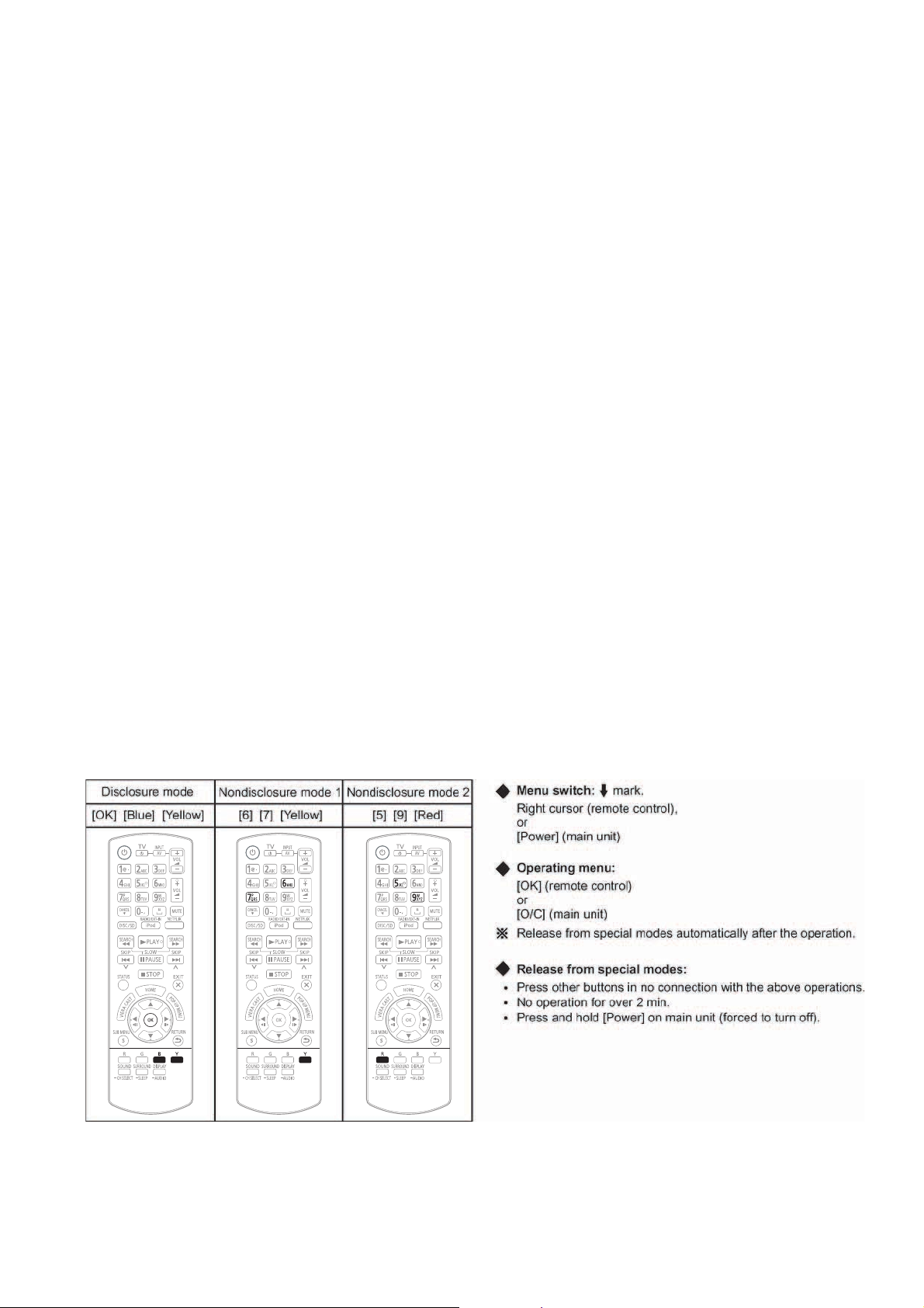
3.3. Entering Special Modes with Combination of Multiple Pressing on the
Remote Control
Enter the following special mode by multiple pressing functions on the supplied remote control.
After entering each mode, switch to the desired menus for operation.
3.3.1. Disclosure mode (Combination of multiple pressing: [OK] [BLUE] [YELLOW])
Press and hold [OK] [BLUE] [YELLOW] on the remote control simultaneously for 5sec., then “00 RET” is displayed on FL display
window.
9
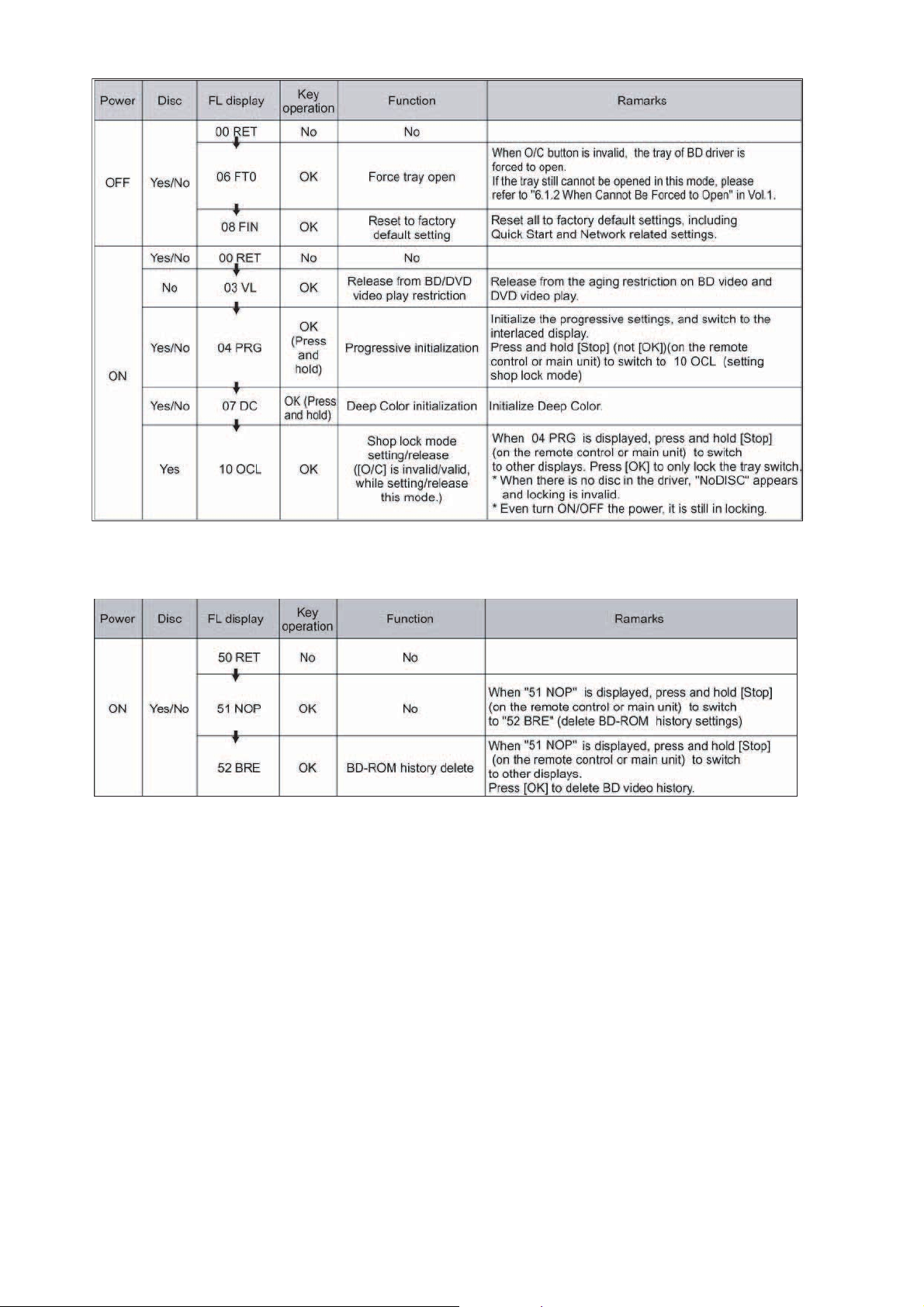
3.3.2. Nondisclosure mode 1 (Combination of multiple pressing: [6] [7] [Yellow])
Press and hold [6] [7] [Yel low] on the remote control simultaneously for 5sec., then “50 RET” is displayed on FL display window.
10
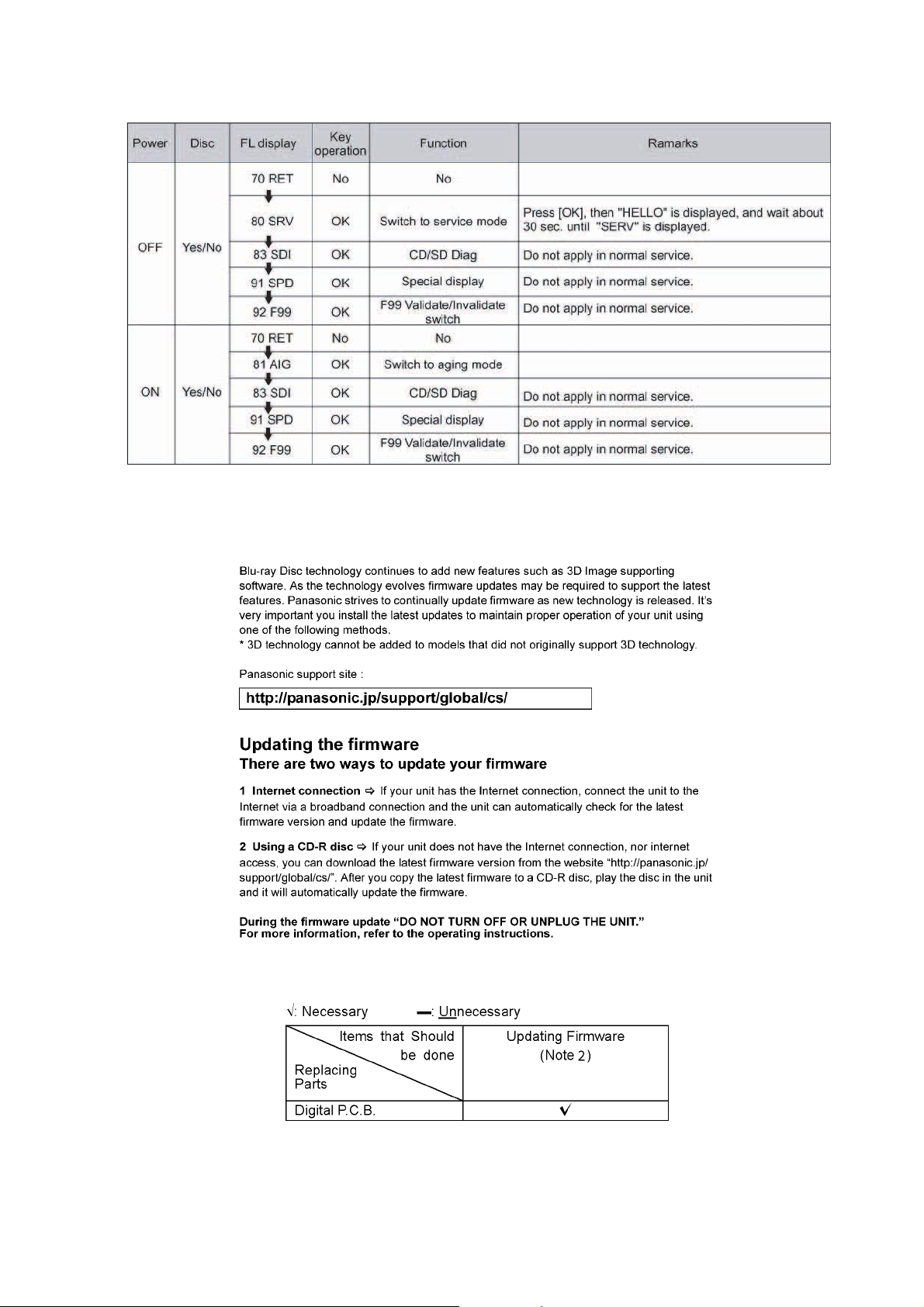
3.3.3. Nondisclosure mode 2 (Combination of multiple pressing: [5] [9] [Red])
Press and hold [5] [9] [Red] on the remote control simultaneously for about 5sec., then “70 RET” is displayed on FL display window.
3.4. Caution for Replacing Parts
3.4.1. Firmware updates
3.4.2. Items that should be done after replacing parts
Note:
Download latest Firmware and burn it on CD-R or CD-RW, and update Firmware.
11
3.4.3. Standard Inspection Specifications after Making Repairs
After making repairs, we recommend performing the following inspection, to check normal operation.
No. Procedure Item to Check
1 Turn on the power, and confirm items pointed out. Items pointed out should reappear.
2 Insert RAM disc. The Panasonic RAM disc should be recognized.
4 Perform playback for one minute using the RAM disc. No abnormality should be seen in the picture, sound or operation.
*Panasonic DVD-RAM disc should be used when recording and play-
back.
5 Perform playback for one minute using the BD-Video disc. No abnormality should be seen in the picture, sound or operation.
6 If a problem is caused by a BD-Video disc, VCD, DVD-R, DVD-
Video, Audio-CD, or MP3, playback the test disc.
7 After checking and making repairs, upgrade the firmware to the
latest version.
8 Transfer [9][9] in the service mode setting, and initialize the ser-
vice settings (return various settings and error information to
their default values. The laser time is not included in this initialization).
Use the following checklist to establish the judgment criteria for the picture and sound.
Item Contents Check Item Contents Check
Picture Block noise Sound Distorted sound
Crosscut noise Noise (static, background noise, etc.)
Dot noise The sound level is too low.
Picture disruption The sound level is too high.
Not bright enough The sound level changes.
Too bright
Flickering color
Color fading
No abnormality should be seen in the picture, sound or operation.
Make sure that [UPD OK] appears in the FL displays.
*[UNSUPPORT] display means the unit is already updated to newest
same version. Then version up is not necessary.
Make sure that [CLR] appears in the FL display.
After checking it, turn the power off.
12
4 Specifications
Main unit SA-BTT270P/PC/SA-BTT268P
OGENERAL
Power supply: AC 120 V, 60 Hz
Power consumption: 85 W
Power consumption in standby mode:
0.4 W
iPod/iPhone Connector: DC OUT 5V 1.0A MAX
Dimensions (W××××H××××D) 430 mm×38 mm×279 mm
Mass (Weight): Approx. 2.7 kg (6.0 lbs)
(Dimensions and Weight do not
Operating temperature range: 0 °C to 40 °C
Operating humidity range: 35 % to 80 % RH
OAMPLIFIER SECTION
RMS TTL Power Output: 1000 W
1 kHz, 10 % total harmonic distortion
Front:
Center:
Surround:
100 Hz, 10 % total harmonic distortion
Subwoofer:
FTC TTL Power Output: 430 W
120 Hz to 20 kHz, 1.0 % total harmonic distortion
Front:
Center:
Surround:
45 Hz to 120 Hz, 1.0 % total harmonic distortion
Subwoofer:
Audio input
AUX x 1
Digital audio input
Optical: x 1
Sampling frequency: 32 kHz, 44.1 kHz, 48 kHz
Audio Format: PCM, Dolby Digital, DTS
OFM TUNER SECTION
Frequency range:
87.90 MHz to 107.90 MHz (200 kHz step)
87.50 MHz to 108.00 MHz (100 kHz step)
Antenna terminals: 75 Ω (unbalanced)
TERMINAL SECTION
SD card slot:
Ethernet:
WLAN (For BTT270 only)
Antenna: Tx 1, Rx 2
Standard Complaince: IEEE802.11n / IEEE802.11a
Transmission System: MISO-OFDM system, OFDM
Transfer rate (Standard):
IEEE802.11n: Tx Max, 150 Mbps, Rx Max.
15
/16”X11/2”X1031/32”)
(16
include Speakers)
(32 °F to 104 °F)
(no condensation)
160 W per ch (3 Ω)
160 W per ch (3 Ω)
160 W per ch (3 Ω)
200 W per ch (3 Ω)
60 W per ch (3 Ω)
90 W per ch (3 Ω)
60 W per ch (3 Ω)
100 W per ch (3 Ω)
Connector: 1 system
10BASE-T/100BASE-TX
1 system
IEEE802.11g / IEEE802.11b
system, DSSS system
300 Mbps
IEEE802.11g / IEEE802.11a: Max. 54 Mbps
IEEE802.11b: Max. 11 Mbps
Access Mode: Infrastructure mode
Security: WPA2-PSK (TKIP/AES)
WPA-PSK (TKIP/AES)
WEP (64 Bit / 128 Bit)
(This unit supports WPA and
WPA2 encryption)
OVIDEO SECTION
Signal system: NTSC
Video output
Output level: 1.0 Vp-p (75 Ω)
Output connector: Pin jack (1 system)
HDMI AV output
Output format:
1080p/ 1080i/ 720p/ 480p
Output connector: Type A (19 pin)
This unit supports “HDAVI Control 5” function.
LASER Specification
Class I LASER Product
Wave length:
790 nm (CDs)/655 nm (DVDs)/405 nm (BDs)
Laser power:
No hazardous radiation is emitted with the safety protection
Note:
1. Specifications are subject to change without notice.
Solder:
This model uses lead free solder (PbF).
Refer to their respective original service manuals for *1.
13
4.1. Others (Licenses)
14
5 Location of Controls and Components
5.1. Remote Control Key Button Operations
15
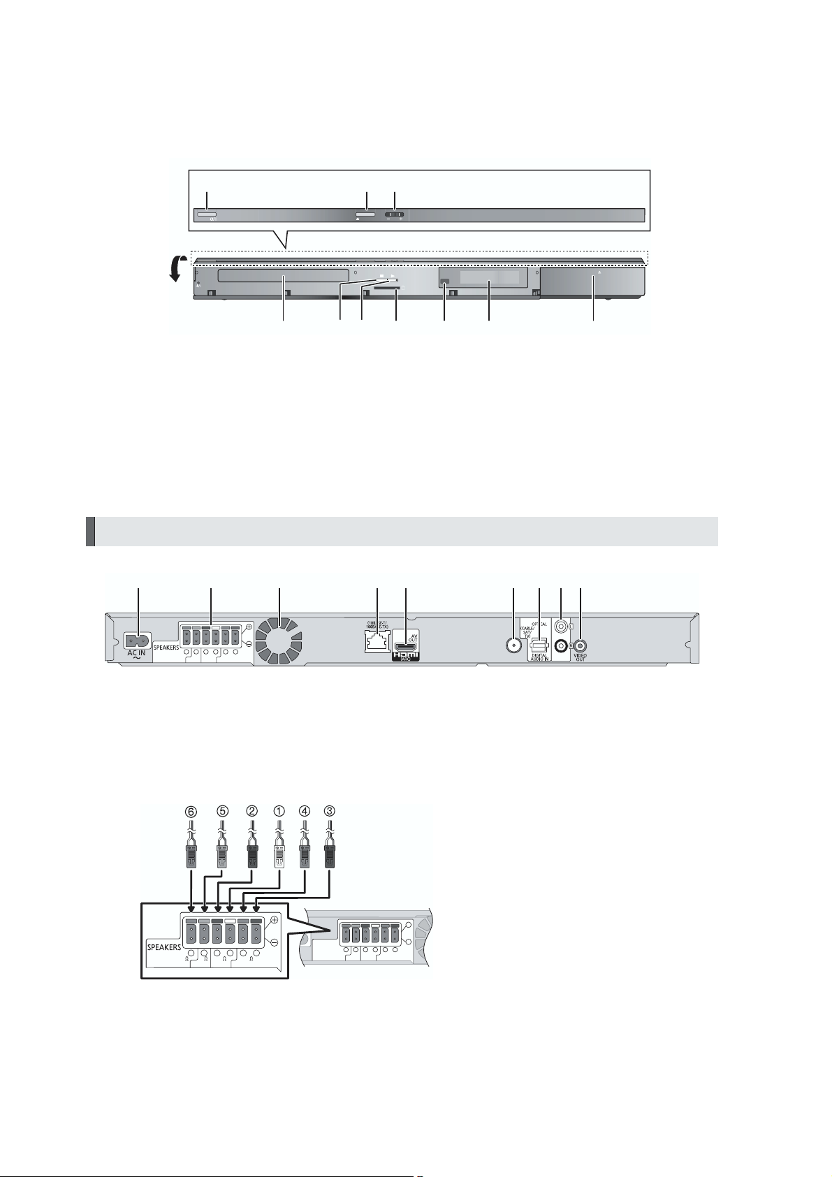
5.2. Main Unit Key Button Operations
123
OPEN/CLOSE
VOLPOWER
Pull open.
1 Standby/on switch (POWER )
Press to switch the unit from on t8o standby mode or vice
versa. In standby mode, the unit is still consuming a small
amount of power.
2 Open or close the disc tray
3 Adjust the volume of the main unit
4 Disc tray
Main unit (Rear)
1 2 3 4 5 8 96 7
6 5 2 1 4 3
RL R L
3
33
3
CENTER
SU RRO UND
SU BWOOFER
FRONT
SD CARD
87654109
5Stop
6 Start play
7 SD card slot
8 Remote control signal sensor
Distance: Within approx. 7 m (23 ft.)
Angle: Approx. 20
9 Display (FL display)
10 Connect iPod/iPhone
LA N
iPod
o
up and down, 30 left and right
FM ANT
75
AUX
1 AC IN terminal
2 Speaker terminals
3 Cooling fan
4 LAN port
5 HDMI AV OUT (ARC) terminal
5.3. Speaker Connection
6 5 2 1 4 3
6 5 2 1 4 3
RL R L
RL R L
3
SU BWOOFER
SU BWOOFER
3
CENTER
CENTER
33
33
FR ONT
FR ONT
SU RRO UND
SU RRO UND
3
3
Main unit
6 FM radio antenna terminal
7 DIGITAL AUDIO IN terminal
8 AUX terminal
9 VIDEO OUT terminal
PURPLE Subwoofer
GREEN Center speaker
RED Front speaker (Rch)
WHITE Front speaker (Lch)
GRAY Surround speaker (Rch)
BLUE Surround speaker (Lch)
16

5.4. Power Saving Features
The main unit is designed to conserve its power consumption and save energy.
POWER-SAVING FEATURES
Automatic power-down function
The main unit will automatically switch to standby mode after
30 minutes if the main unit is inactive as follows.
e.g.
_
There is no audio signal from an external device.
_
Disc playback is stopped/paused.
_
iPod/iPhone playback is stopped/paused.
_
The disc menu is displayed and play is not selected.
(This function may not work depending on the application
type of discs.)
17
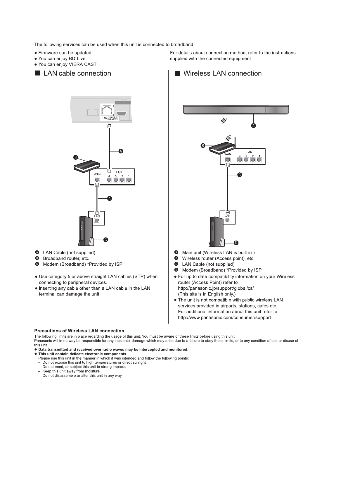
5.5. Connection to a Broadband Network
18
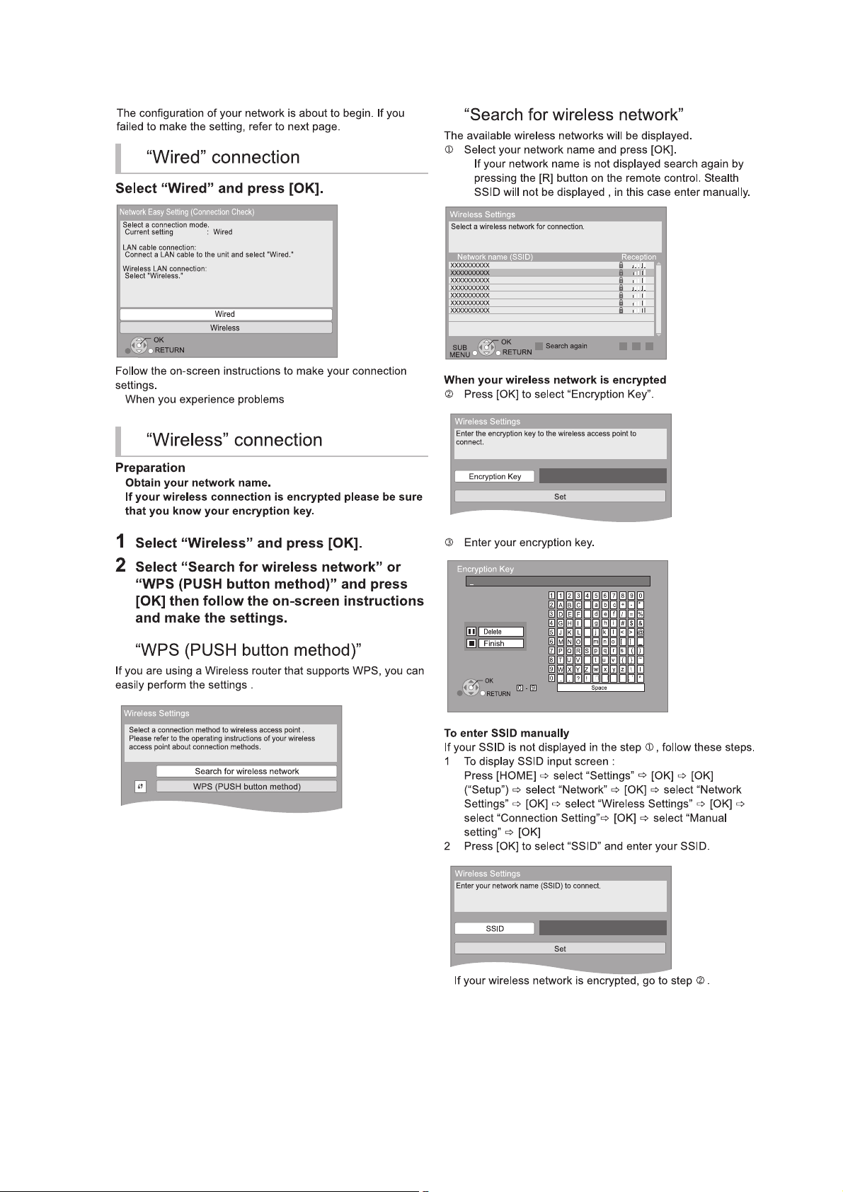
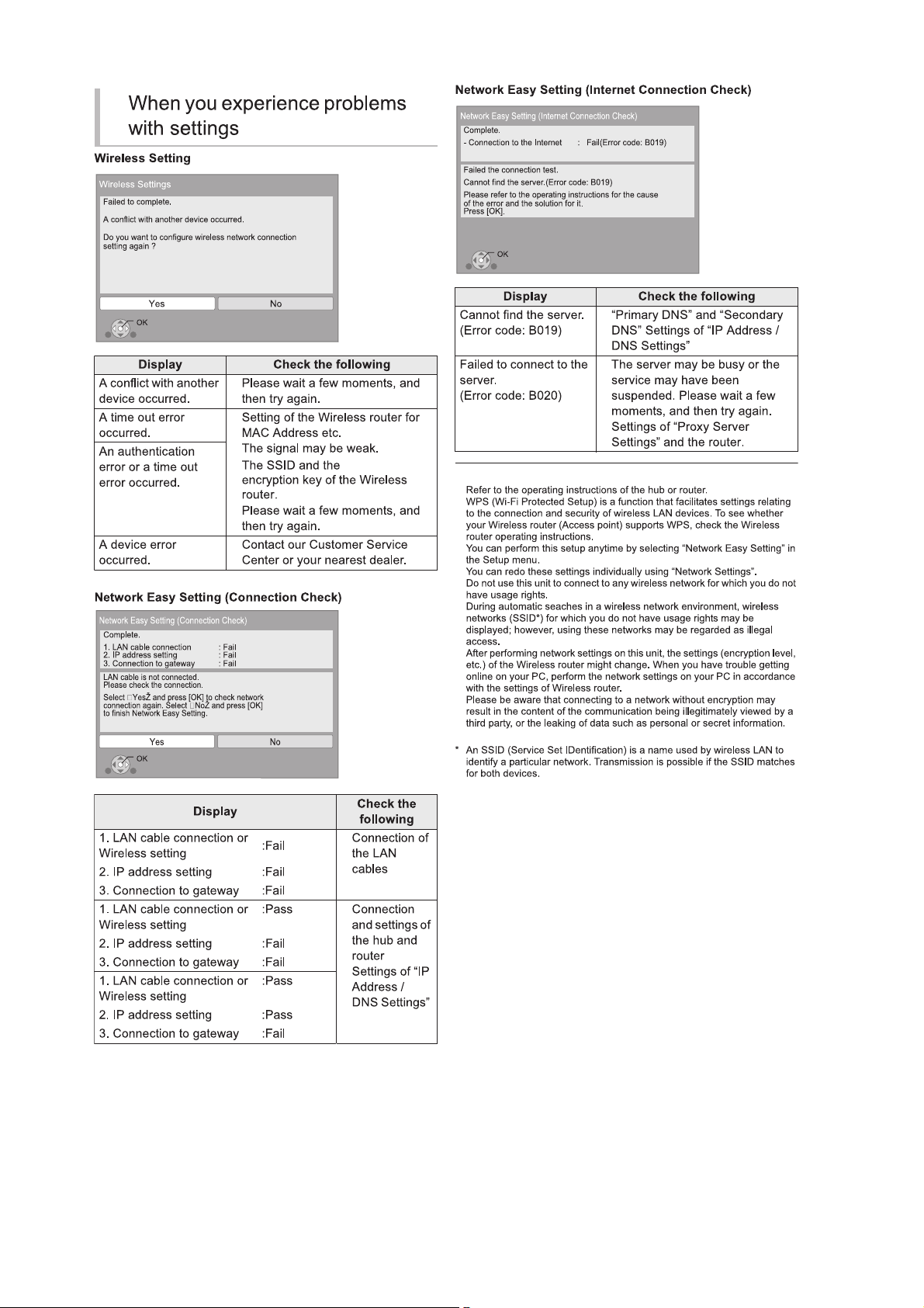
5.6. Network Easy Setting
19
20
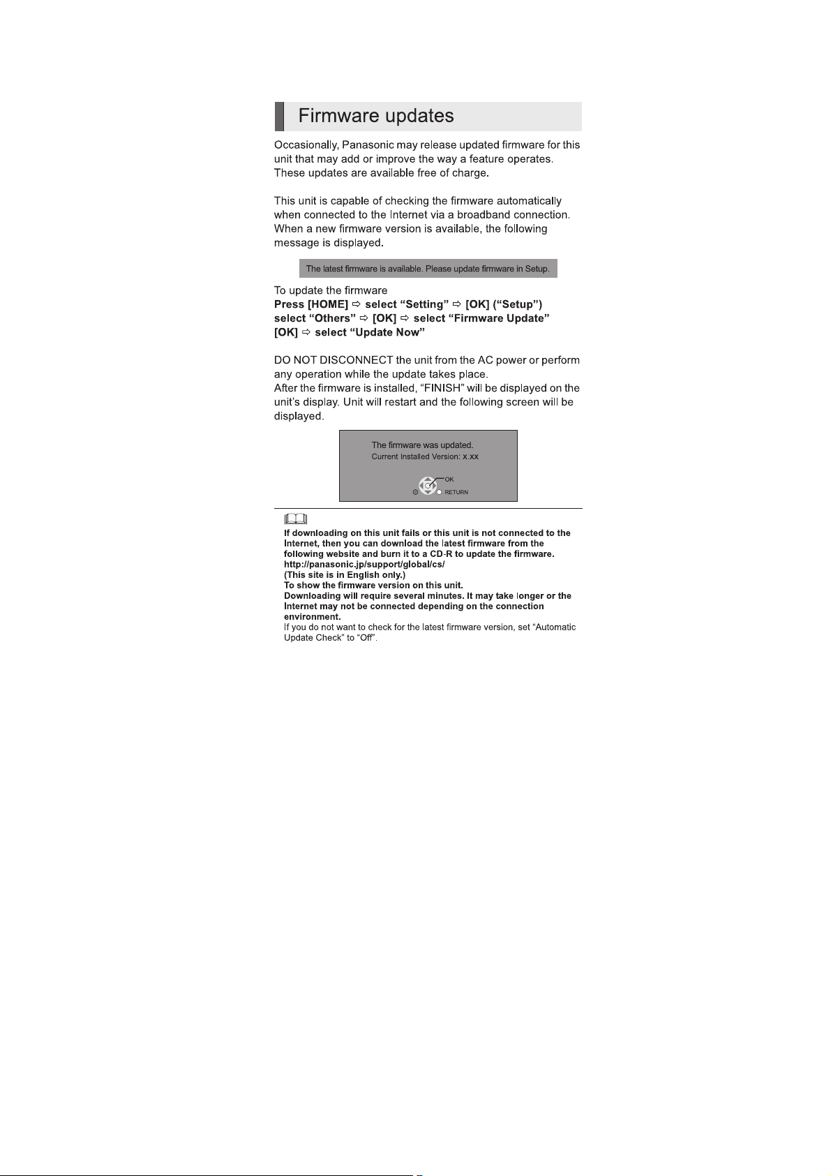
5.7. Firmware Updates
21
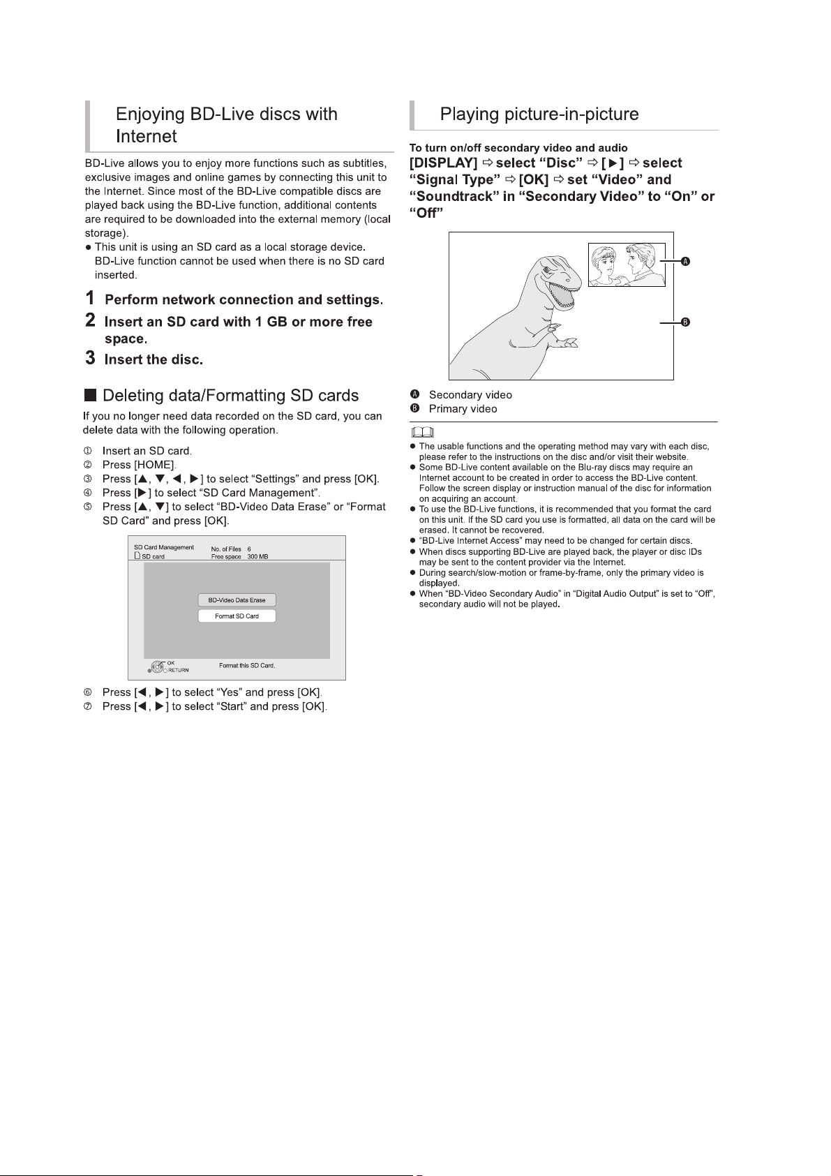
5.8. Enjoying BD-LIVE or Picture-in-picture in BD-Video
22
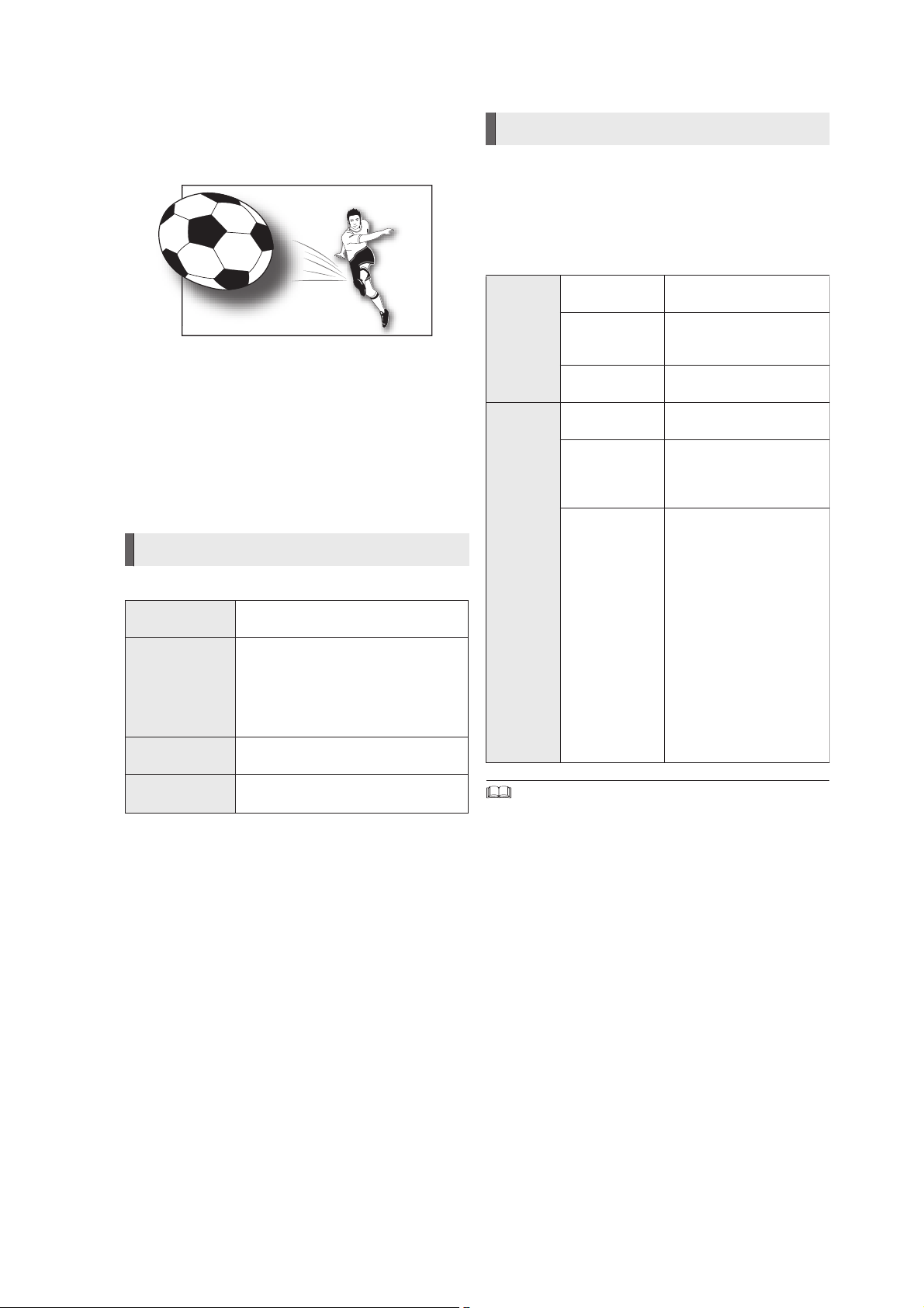
5.9. Enjoying 3D Video
You can enjoy powerful 3D videos with realistic sensations by
connecting this unit with a High Speed HDMI Cable to a 3D
compatible TV.
The illustration is an image.
Preparation
Connect 3D compatible TV to an HDMI AV OUT terminal of
this unit using a High Speed HDMI Cable and select HDMI
video input mode on the TV.
*
Perform the necessary preparations for the TV.
Method of playback is the same as normal disc playback.
*
Playback following the instructions displayed on the screen.
3D settings
Perform the following settings as necessary.
3D BD-Video
Playback
3D Type If 3D video cannot be played back in
3D Playback
Precautions
Pop-Out Level Adjust the pop-up position for the
It is also possible to play back 3D discs
in 2D (conventional video).
3D, change the settings as required by
the connected TV format.
*
Change the settings for 3D on the TV
also when “Checker board” or “Side
by side” is selected.
Hide the 3D viewing warning screen.
Playback menu or message screen etc.
Useful functions
1 While playing,
Press [SUB MENU].
2 Press [ , ] to select “3D Settings” and
e
r
press [OK].
3 Select an item, then press [OK].
Signal
Format
3D
Picture
Mode
*
Depending on the contents, displayed items are different.
*
Please refrain from viewing 3D images if you do not feel well or are
experiencing visual fatigue.
In the event that you experience dizziness, nausea, or other discomfort
while viewing 3D images, discontinue use and rest your eyes.
*
Depending on the connected TV, the video being played back might switch
to 2D video due to changes in resolution etc. Check the 3D setting on the
TV.
*
3D images may not output as settings of “HDMI Resolution” and “24p
Output”.
Original Keep original picture
format.
Side by side 3D picture format
comprising of left and right
screens.
2D to 3D Converts 2D pictures to 3D
Normal Playback pictures with
Soft You can enjoy 3D pictures
Manual
Settings
effect.
normal 3D effects.
with a feeling of
broadness, holding back
the depth perception.
Set 3D effect manually.
Distance
Set the amount of depth
perception.
Screen Type
Selects how the screen
appears during 3D
playback (flat or round).
Frame Width
Set the amount of
feathering at the edge of
screen.
Frame Color
Set the color of feathering
at the edge of screen.
23
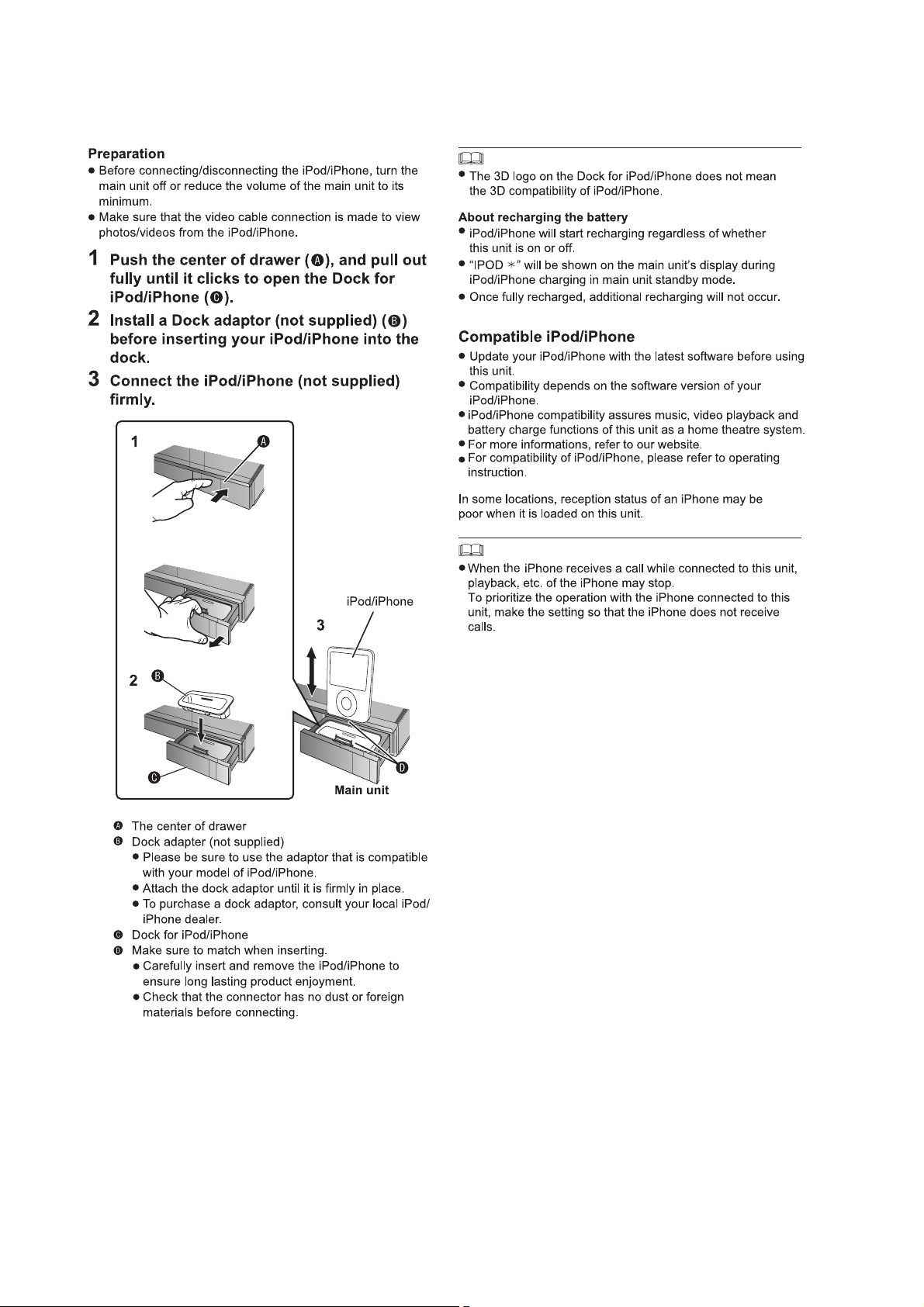
5.10. Using the iPod/iPhone
5.10.1. iPod /iPhone Connection
24
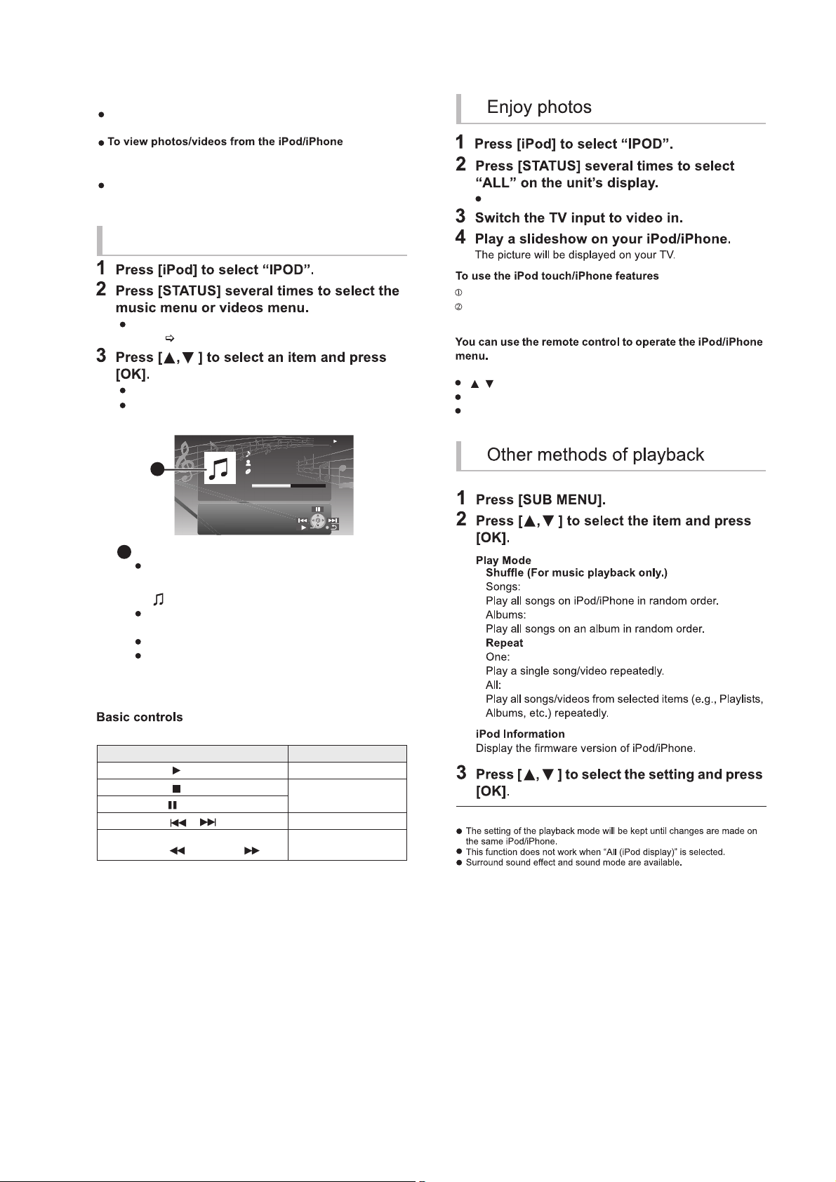
5.10.2. iPod /iPhone Playback
You can also select «All» by using HOME menu.
Press the Home button on the iPod touch/iPhone.
Select the iPod touch/iPhone features on the touch screen
to operate.
The operation may vary among iPod/iPhone models.
[ , ]: To navigate menu items
[OK]: To go to the next menu.
[RETURN]: To return to the previous menu.
Preparation
Make sure that the “IPOD” source is selected. Press [iPod] to
select the source.
Operate the iPod/iPhone menu to make the appropriate
photo/video output settings for your TV.
To display the picture, turn on the TV and select the
appropriate video input mode.
You can also select «Videos» or «Music» by using HOME
menu. (
23)
Repeat this step until the selected title starts playback.
Press [2 , 1 ] to display the previous or next page.
e.g., music playback screen
To exit, press [RETURN].
(For music and video playback only)
Enjoy music/video
Album artwork
If album artwork is contained in the data of a song, it
will appear on the TV. If there is no album artwork,
“ ” will be appear on TV.
Depending on the software version of your iPod/
iPhone, the album artwork may not appear properly.
It may take time to read the album artwork.
Some operations may not work while reading the
album artwork.
Buttons Fu n ctions
[ PLAY] Play
[
STOP]
Pause
[ PAUSE]
[ , ] Skip
(Press and hold)
[SEARCH , SEARCH ]
Search
iPod
R
onaldo
-2:
30
G
oodmorning
45
o
f
1230
H
appydays
1:00
A
A
25
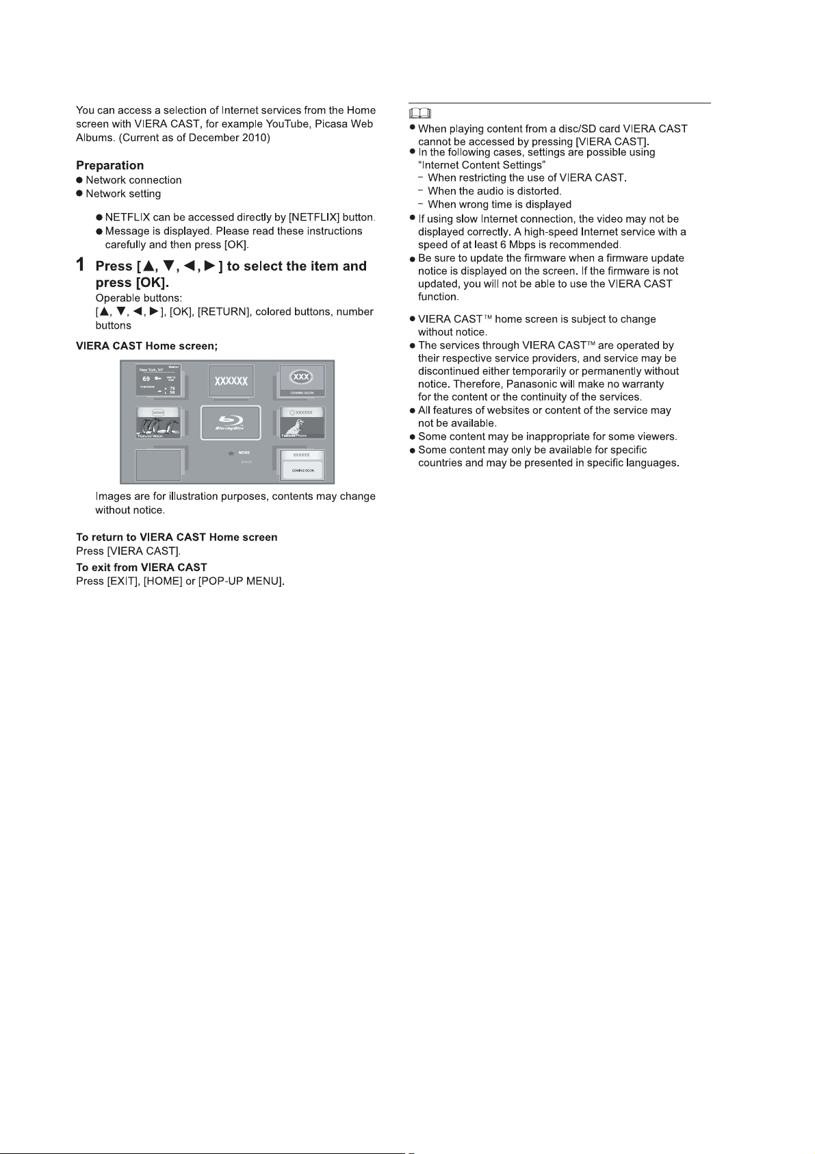
5.11. Enjoying VIERA CAST™
26
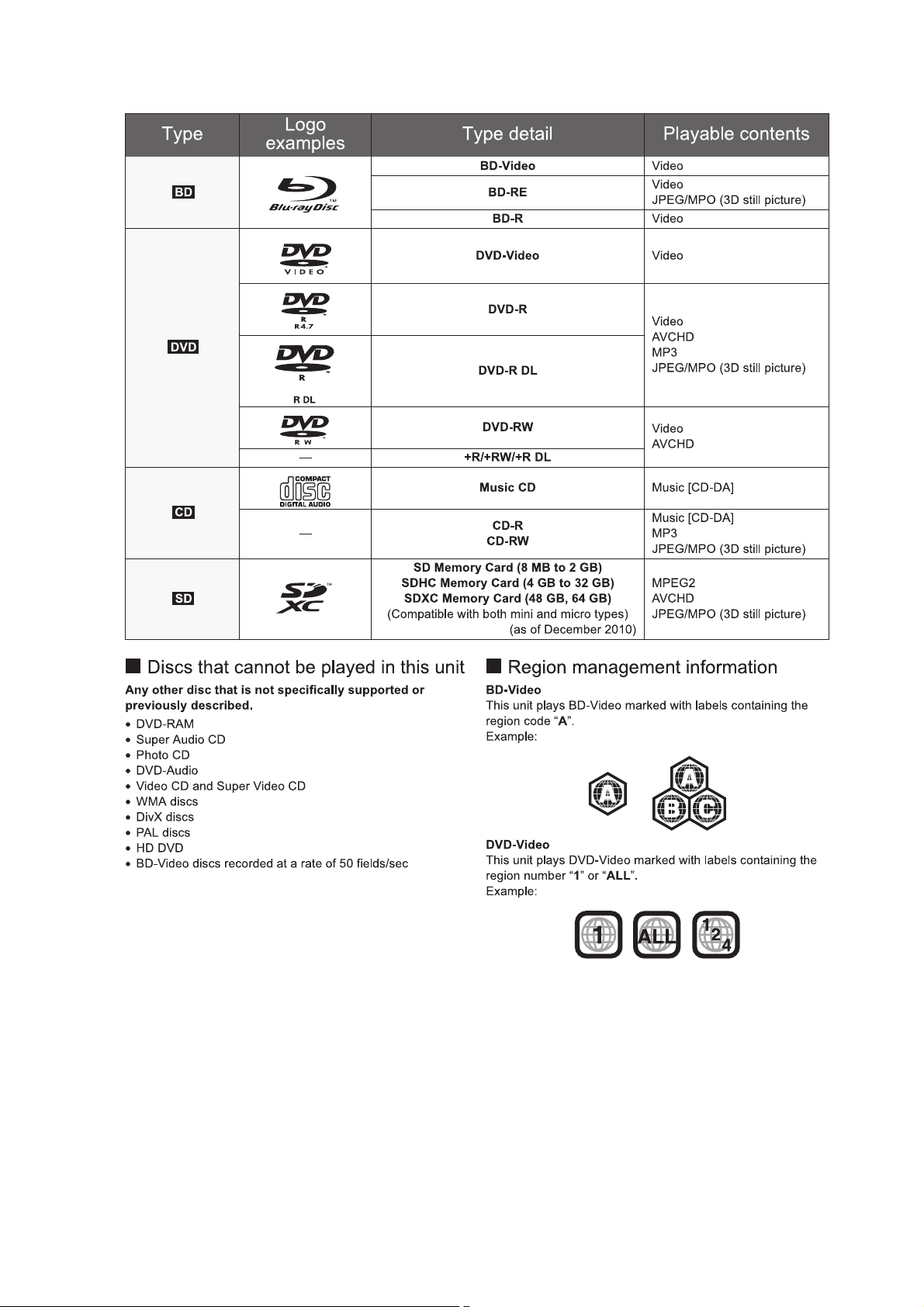
5.12. Playable discs/Cards
27
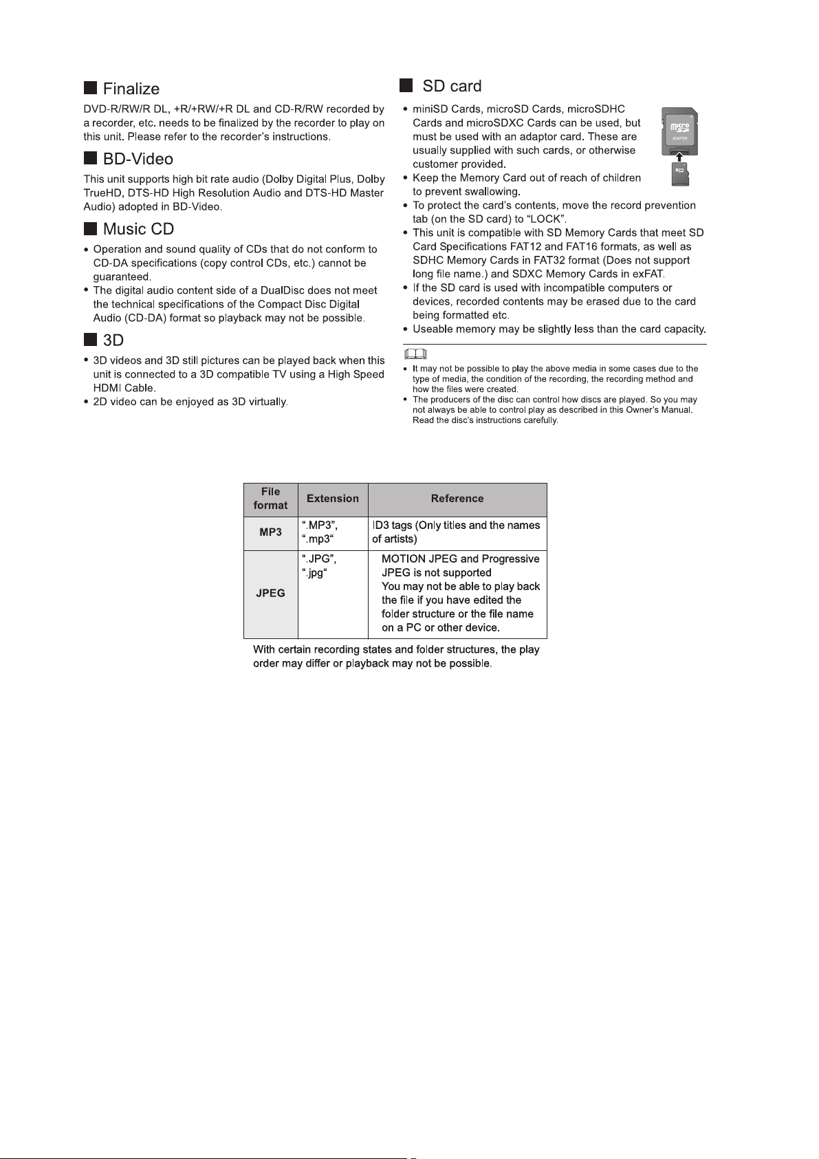
5.13. File Extension Type Support (MP3/JPEG)
28
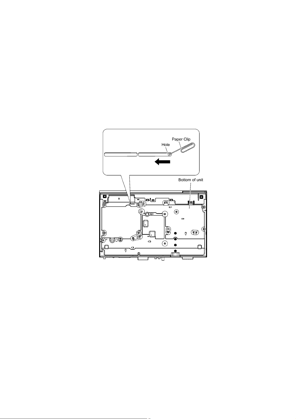
6 Operating Instructions
6.1. Removing of disc during abnormality
6.1.1. Using main unit key buttons.
6.1.1.1. When the power can be turned off.
1. Turn off the power and press & hold [OK] button on main unit, and [B] & [Y] button on remote for 5 seconds.
6.1.1.2. When the power cannot be turned off.
1. Press & hold the [POWER] button to turn off the power forcibly, then press & hold [SKIP FWD] button on remote and [OPEN/
CLOSE] button on main unit for 5 seconds.
6.1.2. When the Forcible Dics Eject cannot be done.
1. Turn off the power and remove AC Cord.
2. Insert Paper Clip. etc. into the hole on the bottom of unit and slid e the Paper Clip on the direction of the arrow to eject tray
slightly. The tray will open automatically.
3. Gently pull out the tray.
29
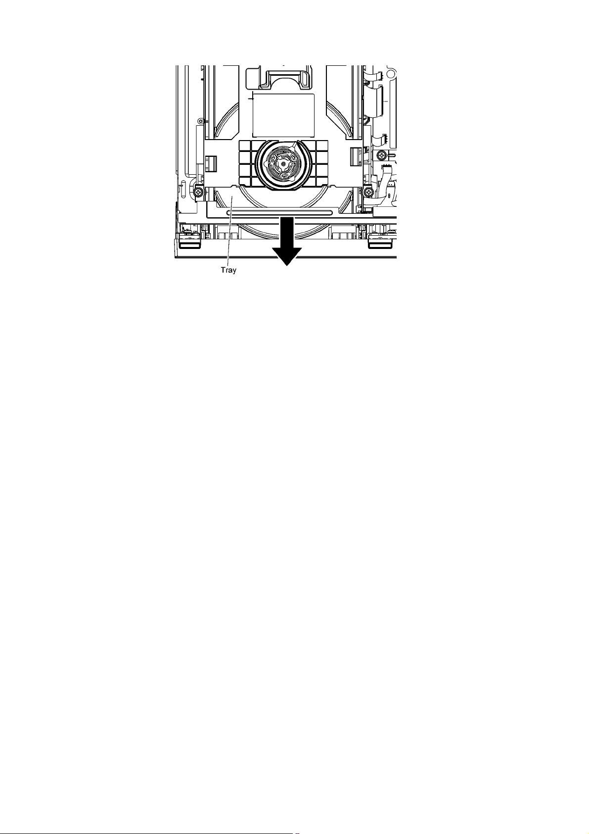
4. Remove disc.
30
Loading…
Panasonic SC-BTT / SA-BTT Series Manual [BTT770,BTT730,BTT270,BTT273
Owner’s Manual
Blu-ray DiscTM Home Theater Sound System
Dear customer
Thank you for purchasing this product.
For optimum performance and safety, please read these instructions carefully.
Before connecting, operating or adjusting this product, please read the instructions completely.
Please keep this manual for future reference.
If you have any questions contact
U.S.A. and Puerto Rico : 1-800-211-PANA(7262)
Canada : 1-800-561-5505
THE FOLLOWING APPLIES ONLY IN THE U.S.A.
FCC Note:
This equipment has been tested and found to comply with the limits for a
Class B digital device, pursuant to Part 15 of the FCC Rules.
These limits are designed to provide reasonable protection against
harmful interference in a residential installation. This equipment
generates, uses, and can radiate radio frequency energy and, if not
installed and used in accordance with the instructions, may cause harmful
interference to radio communications.
However, there is no guarantee that interference will not occur in a
particular installation. If this equipment does cause harmful interference to
radio or television reception, which can be determined by turning the
equipment off and on, the user is encouraged to try to correct the
interference by one or more of the following measures:
≥ Reorient or relocate the receiving antenna.
≥ Increase the separation between the equipment and receiver.
≥ Connect the equipment into an outlet on a circuit different from that to
which the receiver is connected.
≥ Consult the dealer or an experienced radio/TV technician for help.
FCC Caution:To assure continued compliance, follow the attached
installation instructions and use only shielded interface cables when
connecting to peripheral devices. Any changes or modifications not
expressly approved by the party responsible for compliance could void the
user’s authority to operate this equipment.
This device complies with Part 15 of the FCC Rules.
Operation is subject to the following two conditions:
(1) This device may not cause harmful interference, and
(2) this device must accept any interference received, including
interference that may cause undesired operation.
Responsible Party:
Panasonic Corporation of North America
One Panasonic Way
Secaucus, NJ 07094
Support Contact:
Panasonic Consumer Electronics Company
Telephone No.: 1-800-211-PANA (7262)
THE FOLLOWING APPLIES IN THE U.S.A. AND CANADA
This device complies with Part 15 of FCC Rules and RSS-Gen of IC Rules.
Operation is subject to the following two conditions:
(1) This device may not cause interference, and (2) this device must accept
any interference, including interference that may cause undesired operation
of this device.
Contains FCC ID: RYYWYPAEBUX4
Contains IC:4389B-WYPAEBUX4
This transmitter must not be co-located or operated in conjunction with any
other antenna or transmitter.
This product is restricted to indoor use due to its operation in the 5.15 to
5.25 GHz frequency range.
FCC and IC require this product to be used indoors for the frequency range
5.15 to 5.25 GHz to reduce the potential for harmful interference to
co-channel Mobile Satellite systems. High power radars are allocated as
primary users of the 5.25 to 5.35 GHz and 5.65 to 5.85 GHz bands. These
radar stations can cause interference with and/or damage this product.
This equipment complies with FCC/IC radiation exposure limits set forth for
an uncontrolled environment and meets the FCC radio frequency (RF)
Exposure Guidelines in Supplement C to OET65 and RSS-102 of the IC
radio frequency (RF) Exposure rules. This equipment has very low levels of
RF energy that it deemed to comply without maximum permissive exposure
evaluation (MPE). But it is desirable that it should be installed and operated
keeping the radiator at least 20cm or more away from person’s body
(excluding extremities: hands, wrists, feet and ankles).
[BTT770]
THE FOLLOWING APPLIES ONLY IN THE U.S.A.
FCC Note:
This equipment has been tested and found to comply with the limits for a
Class B digital device, pursuant to Part 15 of the FCC Rules.
These limits are designed to provide reasonable protection against
harmful interference in a residential installation. This equipment
generates, uses and can radiate radio frequency energy and, if not
installed and used in accordance with the instructions, may cause harmful
interference to radio communications.
However, there is no guarantee that interference will not occur in a
particular installation. If this equipment does cause harmful interference to
radio or television reception, which can be determined by turning the
equipment off and on, the user is encouraged to try to correct the
interference by one or more of the following measures:
≥ Reorient or relocate the receiving antenna.
≥ Increase the separation between the equipment and receiver.
≥ Connect the equipment into an outlet on a circuit different from that to
which the receiver is connected.
≥ Consult the dealer or an experienced radio/TV technician for help.
FCC caution: To maintain compliance with FCC regulations, shielded
interface cables must be used with this equipment. Operation with
non-approved equipment or unshielded cables may result in interference
to radio and TV reception. Any changes or modifications not approved by
the party responsible for compliance could void the user’s authority to
operate this equipment.
This device complies with Part 15 of the FCC Rules.
Operation is subject to the following two conditions:
(1) This device may not cause harmful interference, and
(2) this device must accept any interference received, including
interference that may cause undesired operation.
Responsible Party:
Panasonic Corporation of North America
One Panasonic Way, Secaucus, NJ 07094
Support Contact:
Panasonic Consumer Electronics Company
Telephone No.: 1-800-211-PANA (7262)
WARNING:
To satisfy FCC RF exposure requirements for mobile transmitting devices,
a separation distance of 20 cm or more should be maintained between the
antenna of this device and persons during device operation.
To ensure compliance, operations at closer than this distance is not
recommended. The antenna used for this transmitter must not be
co-located in conjunction with any other antenna or transmitter.
[BTT770]
THE FOLLOWING APPLIES ONLY IN CANADA.
This Class B digital apparatus complies with Canadian ICES-003.
[BTT770] [BTT370]
THE FOLLOWING APPLIES ONLY IN CANADA.
For main unit
Product Identification Marking is located on the bottom of the unit.
[BTT770]
For wireless system
Product Identification Marking is located on the bottom of wireless system.
IMPORTANT SAFETY
INSTRUCTIONS
Read these operating instructions carefully before using the unit. Follow the
safety instructions on the unit and the applicable safety instructions listed
below. Keep these operating instructions handy for future reference.
1 Read these instructions.
2 Keep these instructions.
3 Heed all warnings.
4 Follow all instructions.
5 Do not use this apparatus near water.
6 Clean only with dry cloth.
7 Do not block any ventilation openings. Install in accordance with the manufacturer’s instructions.
8 Do not install near any heat sources such as radiators, heat registers,
stoves, or other apparatus (including amplifiers) that produce heat.
9 Do not defeat the safety purpose of the polarized or grounding-type plug.
A polarized plug has two blades with one wider than the other.
A grounding-type plug has two blades and a third grounding prong. The
wide blade or the third prong are provided for your safety. If the provided
plug does not fit into your outlet, consult an electrician for replacement of
the obsolete outlet.
10 Protect the power cord from being walked on or pinched particularly at
plugs, convenience receptacles, and the point where they exit from the
apparatus.
11 Only use attachments/accessories specified by the manufacturer.
12 Use only with the cart, stand, tripod, bracket, or table
specified by the manufacturer, or sold with the
apparatus. When a cart is used, use caution when
moving the cart/apparatus combination to avoid injury from tip-over.
13 Unplug this apparatus during lightning storms or when unused for long periods of time.
14 Refer all servicing to qualified service personnel. Servicing is required
when the apparatus has been damaged in any way, such as
power-supply cord or plug is damaged, liquid has been spilled or objects
have fallen into the apparatus, the apparatus has been exposed to rain
or moisture, does not operate normally, or has been dropped.
WARNING
Unit
To reduce the risk of fire, electric shock or product damage,
– Do not expose this unit to rain, moisture, dripping or splashing.
– Do not place objects filled with liquids, such as vases, on this unit.
– Use only the recommended accessories.
– Do not remove covers.
– Do not repair this unit by yourself. Refer servicing to qualified service
personnel.
CAUTION
Unit
– This unit utilizes a laser. Use of controls or adjustments or performance of
procedures other than those specified herein may result in hazardous
radiation exposure.
– Do not place sources of naked flames, such as lighted candles, on this unit.
Placement
To reduce the risk of fire, electric shock or product damage,
– Do not install or place this unit in a bookcase, built-in cabinet or in another
confined space. Ensure this unit is well ventilated.
– Do not obstruct this unit’s ventilation openings with newspapers,
tablecloths, curtains, and similar items
This Owner’s Manual is applicable to models
SC-BTT770, SC-BTT370, SC-BTT270 and SC-BTT273.
Unless otherwise indicated, illustrations in this Owner’s
Manual are of SC-BTT770.
≥ Operations in this Owner’s Manual are described mainly
with the remote control, but you can perform the
operations on the main unit if the controls are the same.
Indicates features applicable to:
[BTT770]: SC-BTT770 only
[BTT370]: SC-BTT370 only
[BTT270]: SC-BTT270 only
[BTT273]: SC-BTT273 only
System SC-BTT770 SC-BTT370 SC-BTT270 SC-BTT273
Main unit SA-BTT770 SA-BTT370 SA-BTT270 SA-BTT273
Speaker system Front speakers SB-HF775 SB-HF370 SB-HF270 SB-HF370
Center speaker SB-HC775 SB-HC370 SB-HC270 SB-HC370
Surround speakers SB-HS270 SB-HS270 SB-HS270 SB-HS270
Subwoofer SB-HW370 SB-HW370 SB-HW270 SB-HW270
Wireless system (with digital transmitter) SH-FX71
≥ Some accessories and external devices mentioned in this Owner’s Manual that are not included with this product may not be on sale in certain regions.
≥ Please note that the actual controls and components, menu items, etc. of your Blu-ray Disc Home Theater Sound System may look somewhat different from those shown in the illustrations in this Owner’s Manual.
Accessory
Check the supplied accessories before using this unit.
For accessories of speakers, refer to page 10.
Control reference guide
Remote control
1 Turn the unit on and off
2 Select title numbers, etc./Enter numbers or characters
(? 34)
[CANCEL]: Cancel
3 Select the source (? 22)
4 Basic playback control buttons (? 25)
5 Select preset radio stations
6 Show status messages (? 25)
7 Display the Home screen of VIERA CAST (? 34)
8 Selection/OK, Frame-by-frame (? 25)
9 Show sub menu (? 26)
10 These buttons are used when;
≥ Operating a BD-Video disc that includes JavaTM
applications (BD-J).
≥ Operating contents of VIERA CAST (? 34)
11 Set the sound mode (? 24)/Select speaker channel
(? 24)
12 Select surround sound effects (? 24)/Set the sleep timer
1 Press and hold [–SLEEP].
2 While “SLEEP ££” is displayed, press [–SLEEP]
several times to select the time (in minutes).
≥ Timer selection is up to 120 minutes.
≥ Select “OFF” when canceling the setting.
≥ To confirm the remaining time
Press and hold the button again.
13 TV operation buttons
[Í]: Turn the television on and off
[AV, INPUT]: Switch the input select
[i j VOL]: Adjust the volume
14 Adjust the volume of the main unit
15 Mute the sound
≥ “MUTE” flashes on the unit’s display, while the function is
on.
≥ To cancel, press the button again or adjust the volume.
≥ Muting is canceled if the unit is turned off.
16 Show NETFLIX screen
17 Select radio stations manually (? 29)
18 Exit the menu screen
19 Show HOME menu (? 23)
20 Show Pop-up menu/Top menu/Direct Navigator (? 25)
21 Return to previous screen
22 [BTT770] [BTT370] : Start up a video communication (? 34)
23 Show Playback menu (? 35)/Select audio (? 25)
Main unit (Front)
1 Standby/on switch (POWER Í/I) (? 19)
Press to switch the unit from on to standby mode or vice
versa. In standby mode, the unit is still consuming a small
amount of power.
2 Open or close the disc tray (? 22)
3 Adjust the volume of the main unit
4 Disc tray
5 Stop (? 25)
6 Start play (? 25)
7 SD card slot (? 22)
8 Remote control signal sensor
Distance: Within approx. 7 m (23 ft.)
Angle: Approx. 20o up and down, 30o left and right
9 Display
10 Connect iPod/iPhone (? 32)
POWER-SAVING FEATURES
The main unit is designed to conserve its power consumption and save energy.
[BTT770] [BTT370] Wireless system (SH-FX71) does not have this function.
≥ Automatic power-down function
The main unit will automatically switch to standby mode after
30 minutes if the main unit is inactive as follows.
e.g.
jThere is no audio signal from an external device.
jDisc playback is stopped/paused.
jiPod/iPhone playback is stopped/paused.
jThe disc menu is displayed and play is not selected.
(This function may not work depending on the application
type of discs.)
1 AC IN terminal (? 18)
2 Speaker terminals (? 13)
3 Cooling fan
4 [BTT770] [BTT370] USB port for the Communication Camera
TY-CC10W (optional) (? 34)
5 LAN port (? 17)
6 HDMI AV OUT (ARC) terminal (? 15)
7 [BTT770] [BTT370] HDMI 1 IN (CABLE/SAT) terminal (? 16)
8 [BTT770] [BTT370] HDMI 2 IN terminal (? 16)
9 FM radio antenna terminal (? 16)
10 DIGITAL AUDIO IN terminal (? 14 , 15)
11 AUX terminal (? 14)
12 VIDEO OUT terminal (? 14)
13 [BTT770] Digital transmitter dock for supplied wireless
system (? 17)
[BTT370] Digital transmitter dock for optional wireless
system (? 12)
Playable discs/Cards
Discs that cannot be played in this unit
Any other disc that is not specifically supported or
previously described.
1. DVD-RAM
2. Super Audio CD
3. Photo CD
4. DVD-Audio
5. Video CD and Super Video CD
6. WMA discs
7. DivX discs
8. PAL discs
9. HD DVD
10 BD-Video discs recorded at a rate of 50 fields/sec
Region management information
BD-Video
This unit plays BD-Video marked with labels containing the
region code “A”.
Example:
DVD-Video
This unit plays DVD-Video marked with labels containing the
region number “1” or “ALL”.
Example:
Finalize
DVD-R/RW/R DL, +R/+RW/+R DL and CD-R/RW recorded by
a recorder, etc. needs to be finalized by the recorder to play on
this unit. Please refer to the recorder’s instructions.
BD-Video
This unit supports high bit rate audio (Dolby Digital Plus, Dolby
TrueHD, DTS-HD High Resolution Audio and DTS-HD Master
Audio) adopted in BD-Video.
Music CD
≥ Operation and sound quality of CDs that do not conform to
CD-DA specifications (copy control CDs, etc.) cannot be
guaranteed.
≥ The digital audio content side of a DualDisc does not meet
the technical specifications of the Compact Disc Digital
Audio (CD-DA) format so playback may not be possible.
3D
≥ 3D videos and 3D still pictures can be played back when this
unit is connected to a 3D compatible TV using a High Speed
HDMI Cable.
≥ 2D video can be enjoyed as 3D virtually. (? 27)
Unit and media care
Using the remote control
More Manuals From Panasonic
Manual
View the manual for the Panasonic SC-BTT270 here, for free. This user manual comes under the category home cinema sets and has been rated by 3 people with an average of a 8. This manual is available in the following languages: English. Do you have a question about the Panasonic SC-BTT270?
Ask your question here
Panasonic SC-BTT270 specifications
Below you will find the product specifications and the manual specifications of the Panasonic SC-BTT270.
Audio system
Dolby Digital Plus / Dolby TrueHD / DTS-HD Master Audio Essential / DTS-HD High Resolution Audio
Center speaker RMS power
160 W
Analog signal format system
NTSC, PAL
Radio Data System (RDS)
Yes
General
| Brand | Panasonic |
| Model | SC-BTT270 | SC-BTT270EG-K |
| Product | home cinema set |
| EAN | 885170029880, 5025232602483 |
| Language | English |
| Filetype | User manual (PDF) |
Audio
| RMS rated power | 1000 W |
| Audio output channels | 5.1 channels |
| Audio formats supported | MP3 |
Other features
| Audio system | Dolby Digital Plus / Dolby TrueHD / DTS-HD Master Audio Essential / DTS-HD High Resolution Audio |
| Image formats supported | JPG |
| Weight | 2700 g |
| Surround speaker weight | 350 g |
| Depth | 279 mm |
| Height | 38 mm |
| Width | 430 mm |
| Power requirements | 220 – 240V AC, 50Hz |
| Tuner type | Digital |
| HDMI | Yes |
Center speaker
| Center speaker RMS power | 160 W |
| Center speaker impedance | 3 Ω |
Subwoofer
| Subwoofer impedance | 3 Ω |
| Subwoofer RMS power | 200 W |
Video
| Analog signal format system | NTSC, PAL |
| Video formats supported | AVCHD, DivX, MKV, MPEG2 |
| 3D | Yes |
Radio
| Radio Data System (RDS) | Yes |
| Preset stations quantity | 30 |
| Supported radio bands | FM |
Optical drive
| Optical disc player type | Blu-Ray |
| Disc types supported | BD-RE, BD-ROM, CD, CD-R, CD-RW, DVD+R, DVD+R DL, DVD+RW, DVD-R, DVD-R DL, DVD-RW |
Weight & dimensions
| Center speaker weight | 500 g |
| Subwoofer weight | 3000 g |
| Front speaker weight | 350 g |
| Center speaker dimensions (WxDxH) | 81 x 70.5 x 145 mm |
| Subwoofer dimensions (W x D x H) | 289.5 x 258 x 145 mm |
| Front speaker dimensions (WxDxH) | 117 x 70.5 x 80 mm |
| Satellite speaker dimensions (WxDxH) | 117 x 70.5 x 80 mm |
Ports & interfaces
| HDMI ports quantity | 1 |
| USB ports quantity | 1 |
| Digital audio optical in | 1 |
| AUX in | Yes |
| Ethernet LAN (RJ-45) ports | 1 |
| USB version | 2.0 |
Power
| Power consumption (standby) | 0.4 W |
| Power consumption (typical) | 85 W |
Network
Technical details
Packaging content
| Remote control included | Yes |
show more
Frequently asked questions
Can’t find the answer to your question in the manual? You may find the answer to your question in the FAQs about the Panasonic SC-BTT270 below.
What is the weight of the Panasonic SC-BTT270?
The Panasonic SC-BTT270 has a weight of 2700 g.
What is the height of the Panasonic SC-BTT270?
The Panasonic SC-BTT270 has a height of 38 mm.
What is the width of the Panasonic SC-BTT270?
The Panasonic SC-BTT270 has a width of 430 mm.
What is the depth of the Panasonic SC-BTT270?
The Panasonic SC-BTT270 has a depth of 279 mm.
What is HDMI?
HDMI stands for High-Definition Multimedia Interface. An HDMI cable is used to transport audio and video signals between devices.
How can I best clean my home cinema set?
A slightly damp cleaning cloth or soft, dust-free cloth works best to remove fingerprints. Dust in hard-to-reach places is best removed with compressed air.
Wat is Dolby Atmos?
Dolby Atmos is a technology that ensures that the sound is reflected from the ceiling to where you are listening. This makes it possible to create a 5.1 effect with only 1 speaker.
Is the manual of the Panasonic SC-BTT270 available in English?
Yes, the manual of the Panasonic SC-BTT270 is available in English .
Is your question not listed? Ask your question here