

PIONEER CORPORATION 4-1, Meguro 1-chome, Meguro-ku, Tokyo 153-8654, Japan
PIONEER ELECTRONICS (USA) INC. P.O. Box 1760, Long Beach, CA 90801-1760, U.S.A.
PIONEER EUROPE NV Haven 1087, Keetberglaan 1, 9120 Melsele, Belgium
PIONEER ELECTRONICS ASIACENTRE PTE. LTD. 253 Alexandra Road, #04-01, Singapore 159936
PIONEER CORPORATION
2
STANDBY/ON
HDMI
1213
DV-410 V-S
53671
TOP MENU MENU
OPEN/CLOSE
ENTER
USBDVD/USB
HOME
RETURN
MENU
9 8
DVD PLAYER
DV-410V-S
DV-410V-K
THIS MANUAL IS APPLICABLE TO THE FOLLOWING MODEL(S) AND TYPE(S).
Model Type Power Requirement Region No. Remarks
DV-410V-S WYXZT5 AC 220 V to 240V 2
DV-410V-S WVXZT5 AC 220 V to 240V 2
DV-410V-S WSXZT5 AC 220 V to 240V 5
DV-410V-K WYXZT5 AC 220 V to 240V 2
DV-410V-K WSXZT5 AC 220 V to 240V 5
ORDER NO.
RRV3738
For details, refer to «Important Check Points for good servicing».
T- Z Z V M AR .
2008 Printed in Japan

1
This service manual is intended for qualified service technicians ; it is not meant for the casual
do-it-yourselfer. Qualified technicians have the necessary test equipment and tools, and have been
trainedto properly and safely repair complex products such as those covered by this manual.
Improperly performed repairs can adversely affect the safety and reliability of the product and may
void the warranty. If you are not qualified to perform the repair of this product properly and safely,
you should not risk trying to do so and refer the repair to a qualified service technician.
WARNING !
THE AEL (ACCESSIBLE EMISSION LEVEL) OF THE LASER POWER OUTPUT IS LESS THAN CLASS 1
BUT THE LASER COMPONENT IS CAPABLE OF EMITTING RADIATION EXCEEDING THE LIMIT FOR
CLASS 1.
A SPECIALLY INSTRUCTED PERSON SHOULD DO SERVICING OPERATION OF THE APPARATUS.
LASER DIODE CHARACTERISTICS
FOR DVD : MAXIMUM OUTPUT POWER : 5 mW
WAVELENGTH : 650 nm
FOR CD : MAXIMUM OUTPUT POWER : 5 mW
WAVELENGTH : 780 nm
Additional Laser Caution
∗ : See page 26.
1.
• Laser diode is driving with Q2303,Q2305(650nm LD) and Q2302,
Q2304(780nm LD)on the DVD MT PCB Assy.
Therefore, when short-circuit between the emitter and collector of these
transistors or the base voltage is supplied for transistors turn on, the
laser oscillates. (failure mode)
• In the test mode ∗ , there is the mode that the laser oscillates except
for the disc judgment and playback. LD ON mode in the test mode
oscillates with the laser forcibly.
2. When the cover is open, close viewing through the objective lens with
the naked eye will cause exposure to the laser beam.
LABEL CHECK
(Printed on the Rear Panel)
Location: inside of the unit
OPEN/C
LOSE
HDMI
HOME
MEN
U
RETURN
ENTER
TOP
MEN
U MEN
U
USB
DVD/USB
ST
ANDBY/O
N
2 3 4
SAFETY INFORMATION
A
B
C
D
E
F
2
1
2 3 4
DV-410V-S

5
6 7 8
A
B
C
D
E
F
DV-410V-S
5
6 7 8
3

1
2 3 4
CONTENTS
SAFETY INFORMATION ……………………………………………………………………………………………………………………………………….2
1. SERVICE PRECAUTIONS ………………………………………………………………………………………………………………………………….5
A
2. SPECIFICATIONS ……………………………………………………………………………………………………………………………………………..7
2.1 ACCESSORIES …………………………………………………………………………………………………………………………………………..7
2.2 SPECIFICATIONS………………………………………………………………………………………………………………………………………..8
2.3 DISC/CONTENT FORMAT ……………………………………………………………………………………………………………………………9
2.4 PANEL FACILITILES…………………………………………………………………………………………………………………………………..11
3. BASIC ITEMS FOR SERVICE……………………………………………………………………………………………………………………………13
3.1 CHECK POINTS AFTER SERVICING…………………………………………………………………………………………………………..13
3.2 PCB LOCATIONS ………………………………………………………………………………………………………………………………………14
3.3 JIGS LIST …………………………………………………………………………………………………………………………………………………15
4. BLOCK DIAGRAM……………………………………………………………………………………………………………………………………………16
4.1 OVERALL WIRING DIAGRAM……………………………………………………………………………………………………………………..16
B
C
D
E
4.2 OVERALL BLOCK DIAGRAM………………………………………………………………………………………………………………………18
4.3 DVD LOADER/MPEG BLOCK DIAGRAM………………………………………………………………………………………………………19
4.4 POWER BLOCK DIAGRAM…………………………………………………………………………………………………………………………20
5. DIAGNOSIS…………………………………………………………………………………………………………………………………………………….21
5.1 TROUBLE SHOOTING ……………………………………………………………………………………………………………………………….21
5.2 METHOD FOR DIAGNOSING DEGRADATION OF THE LDS ON THE PICKUP ASSY ………………………………………25
6. SERVICE MODE ……………………………………………………………………………………………………………………………………………..26
6.1 SERVICE MODE PROCEDURE…………………………………………………………………………………………………………………..26
6.2 SERVICE MODE IN ……………………………………………………………………………………………………………………………………27
6.3 DISPLAY SPECIFICATION OF THE SERVICE MODE ……………………………………………………………………………………28
6.4 FUNCTIONAL SPECIFICATION OF THE SHORTCUT KEY…………………………………………………………………………….29
6.5 FUNCTIONAL SPECIFICATION OF THE SERVICE MODE …………………………………………………………………………….30
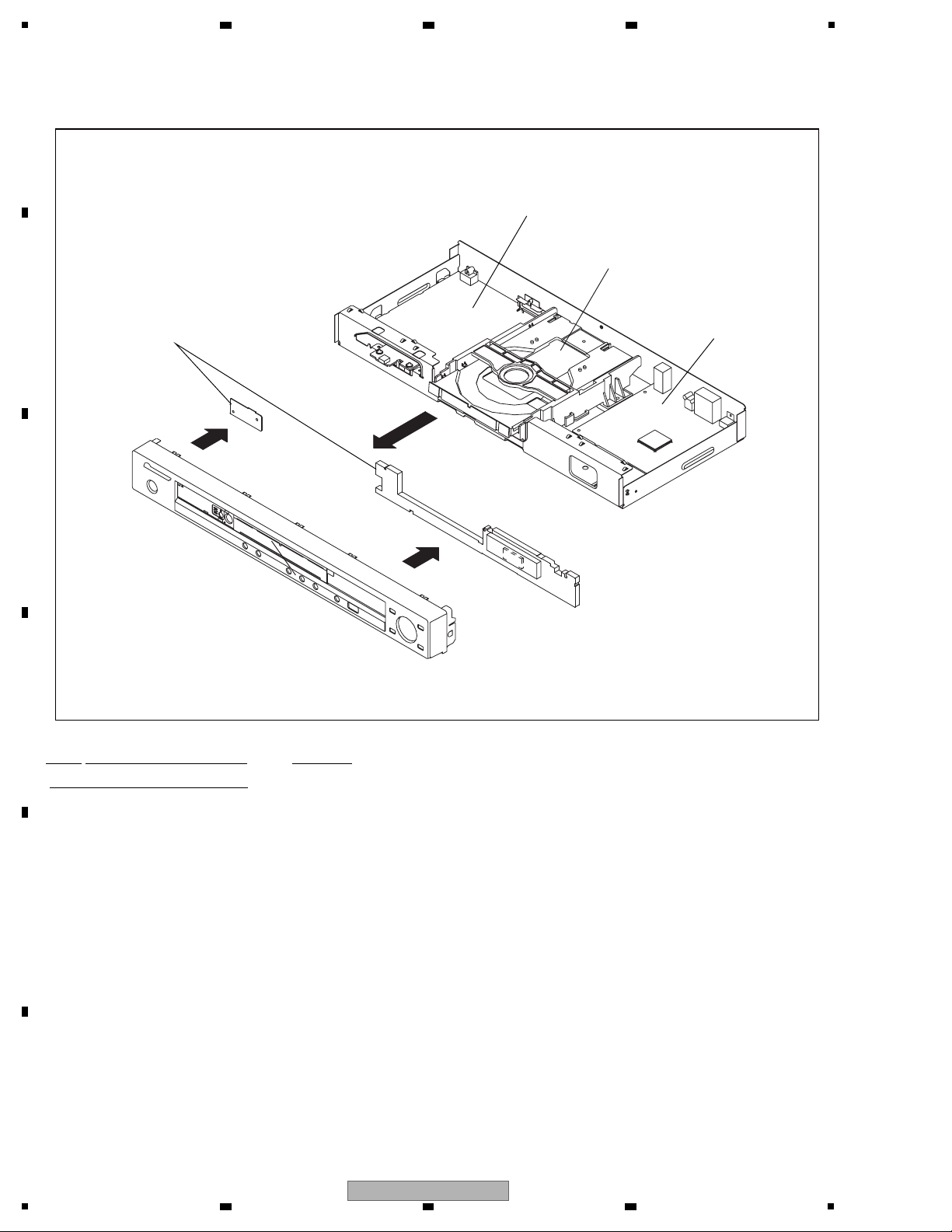
7. DISASSEMBLY………………………………………………………………………………………………………………………………………………..31
7.1 EXTERIOR SECTION…………………………………………………………………………………………………………………………………31
7.2 DVD DECK SECTION…………………………………………………………………………………………………………………………………32
8. EACH SETTING AND ADJUSTMENT ………………………………………………………………………………………………………………..36
8.1 ADJUSTMENT…………………………………………………………………………………………………………………………………………..36
8.2 RE-WRITE FOR DVD FIRMWAVE ……………………………………………………………………………………………………………….36
9. EXPLODED VIEWS AND PARTS LIST……………………………………………………………………………………………………………….38
9.1 PACKING ………………………………………………………………………………………………………………………………………………….38
9.2 EXTERIOR SECTION…………………………………………………………………………………………………………………………………40
9.3 06 DVD MECHA SECTION………………………………………………………………………………………………………………………….42
10. SCHEMATIC DIAGRAM ………………………………………………………………………………………………………………………………….44
10.1 DVD MT PCB ASSY(1/7) …………………………………………………………………………………………………………………………..44
10.2 DVD MT PCB ASSY(2/7) …………………………………………………………………………………………………………………………..46
10.3 DVD MT PCB ASSY(3/7) …………………………………………………………………………………………………………………………..48
10.4 DVD MT PCB ASSY(4/7) …………………………………………………………………………………………………………………………..50
10.5 DVD MT PCB ASSY(5/7) …………………………………………………………………………………………………………………………..52
10.6 DVD MT PCB ASSY(6/7) …………………………………………………………………………………………………………………………..54
10.7 DVD MT PCB ASSY(7/7) …………………………………………………………………………………………………………………………..56
10.8 OPERATION PCB ASSY …………………………………………………………………………………………………………………………..58
10.9 POWER PCB ASSY(1/2) …………………………………………………………………………………………………………………………..60
10.10 POWER PCB ASSY(2/2) …………………………………………………………………………………………………………………………62
10.11 WAVEFORMS………………………………………………………………………………………………………………………………………..64
11. PCB CONNECTION DIAGRAM ……………………………………………………………………………………………………………………….66
11.1 DVD MT PCB ASSY………………………………………………………………………………………………………………………………….67
11.2 OPERATION PCB ASSY …………………………………………………………………………………………………………………………..69
……………………………70
11.3 POWER PCB ASSY……………………………………………………………………………………………….
……
11.4 LOADING MOTOR and SW……………………………………………………………………………………………………………………….72
12. PCB PARTS LIST …………………………………………………………………………………………………………………………………………..73
F
4
1
2 3 4
DV-410V-S
5
• For environmental protection, lead-free solder is used on the printed circuit boards mounted in this unit.
Be sure to use lead-free solder and a soldering iron that can meet specifications for use with lead-free solders for repairs
accompanied by reworking of soldering.
• Compared with conventional eutectic solders, lead-free solders have higher melting points, by approximately 40 °C.
Therefore, for lead-free soldering, the tip temperature of a soldering iron must be set to around 373 °C in general, although
the temperature depends on the heat capacity of the PC board on which reworking is required and the weight of the tip of
the soldering iron.
Do NOT use a soldering iron whose tip temperature cannot be controlled.
Compared with eutectic solders, lead-free solders have higher bond strengths but slower wetting times and higher melting
temperatures (hard to melt/easy to harden).
The following lead-free solders are available as service parts:
• Parts numbers of lead-free solder:
GYP1006 1.0 in dia.
GYP1007 0.6 in dia.
GYP1008 0.3 in dia.
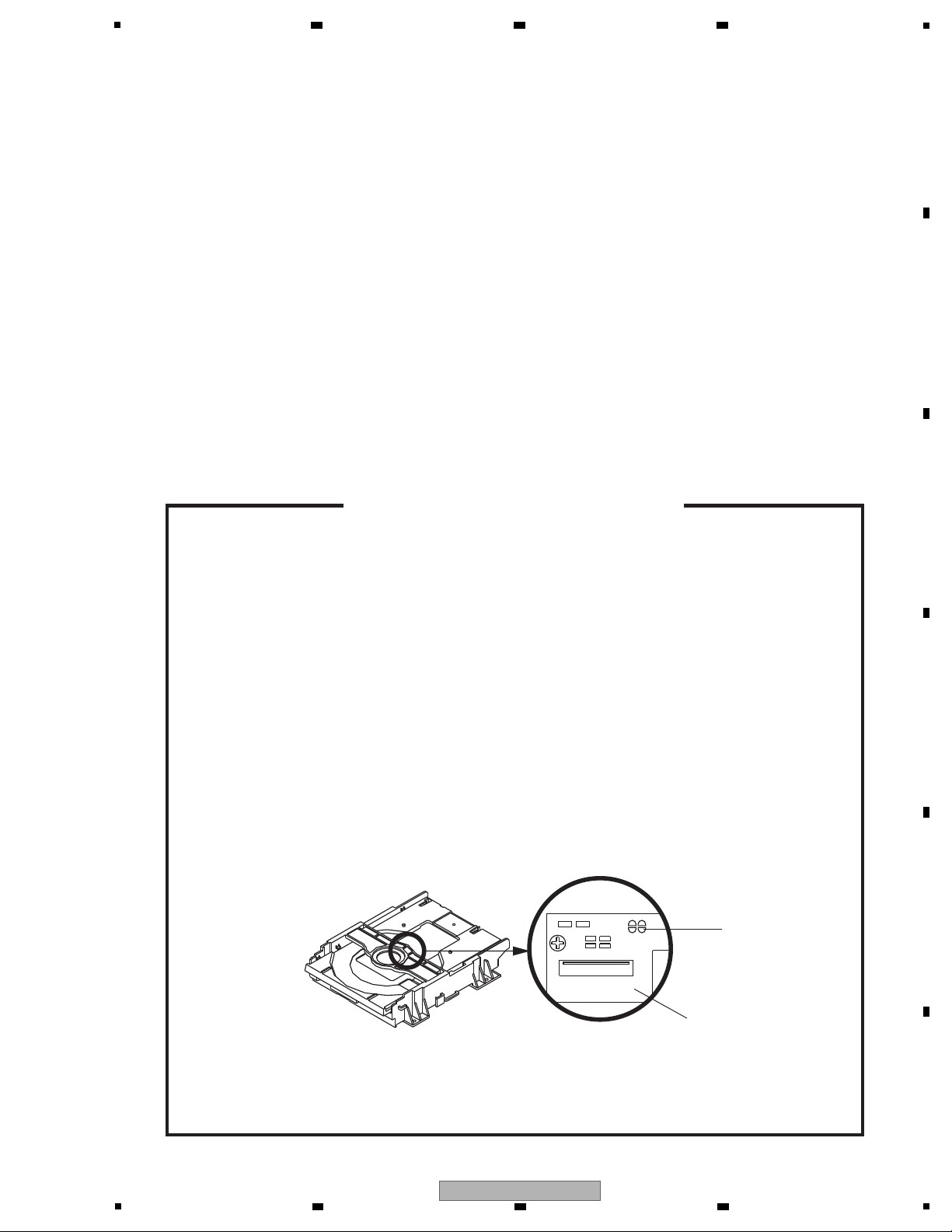
Before removing Pick Up PCB and DVD PCB connector, short circuit the position shown in Fig. 1 using
a soldering iron. If you remove the DVD Deck with no soldering, the Laser may be damaged.
WHEN REPLACING DVD DECK
[ Removing the DVD Deck ]
[ Installing the DVD Deck ]
Remove all the soldering on the short circuit position after the connection of Pick Up PCB and DVD
PCB connector.
NOTE
Fig. 1
Before your operation, please read “PREPARATION OF SERVICING” .
Use the Lead Free solder.
Manual soldering conditions
• Soldering temperature: 320 ± 20°C
• Soldering time: Within 3 seconds
• Soldering combination: Sn-3.0Ag-0.5Cu
When Soldering/Removing of solder, use the draw in equipment over the Pick Up Unit to prevent the
Flux smoke from it.
•
•
•
•
Short circuit using a
soldering iron.
Pick Up PCB
6 7 8
1. SERVICE PRECAUTIONS
A
B
C
D
E
5
6 7 8
DV-410V-S
F
5

1
The laser diode used for a pickup head may be destroyed with external static electricity.
Moreover, even if it is operating normally after repair, when static electricity discharge is
received at the time of repair, the life of the product may be shortened.
Please perform the following measure against static electricity, be careful of destruction of a
laser diode at the time of repair.
¥ Place the unit on a workstation equipped to protect against static electricity, such as
conductive mat.
¥ Soldering iron with ground wire or ceramic type is used.
¥ A worker needs to use a ground conductive wrist strap for body.
PREPARATION OF SERVICING
If the stored 4 digit password in the Rating Level menu needs to be cancelled, please follow the steps
below.
Set the DVD to the Stand-by Mode.
Press and hold the ‘STOP’ key on the front panel.
Simultaneously press and hold the POWER key on the front panel.
The 4 digit password has now been cleared.
1.
2.
3.
4.
PARENTAL CONTROL — RATING LEVEL
4 DIGIT PASSWORD CANCELLATION
NOTE: The above procedure will reset ALL of the player’s settings to the default factory state.
Slide the Rack Loading (White) toward the arrow direction by using a minus driver to release the lock.
(Refer to Fig. 1)
Manually open the Tray.
Please strongly pushing Rack Loading (White) to release the lock because the tray doesn’t go out
easily.
1.
2.
Fig. 1
Rack Loading (White)
DVD Player (Bottom Side)
NOTE:
DISC REMOVAL METHOD AT NO POWER SUPPLY
A
2 3 4
B
C
D
E
F
6
1
2 3 4
DV-410V-S
5
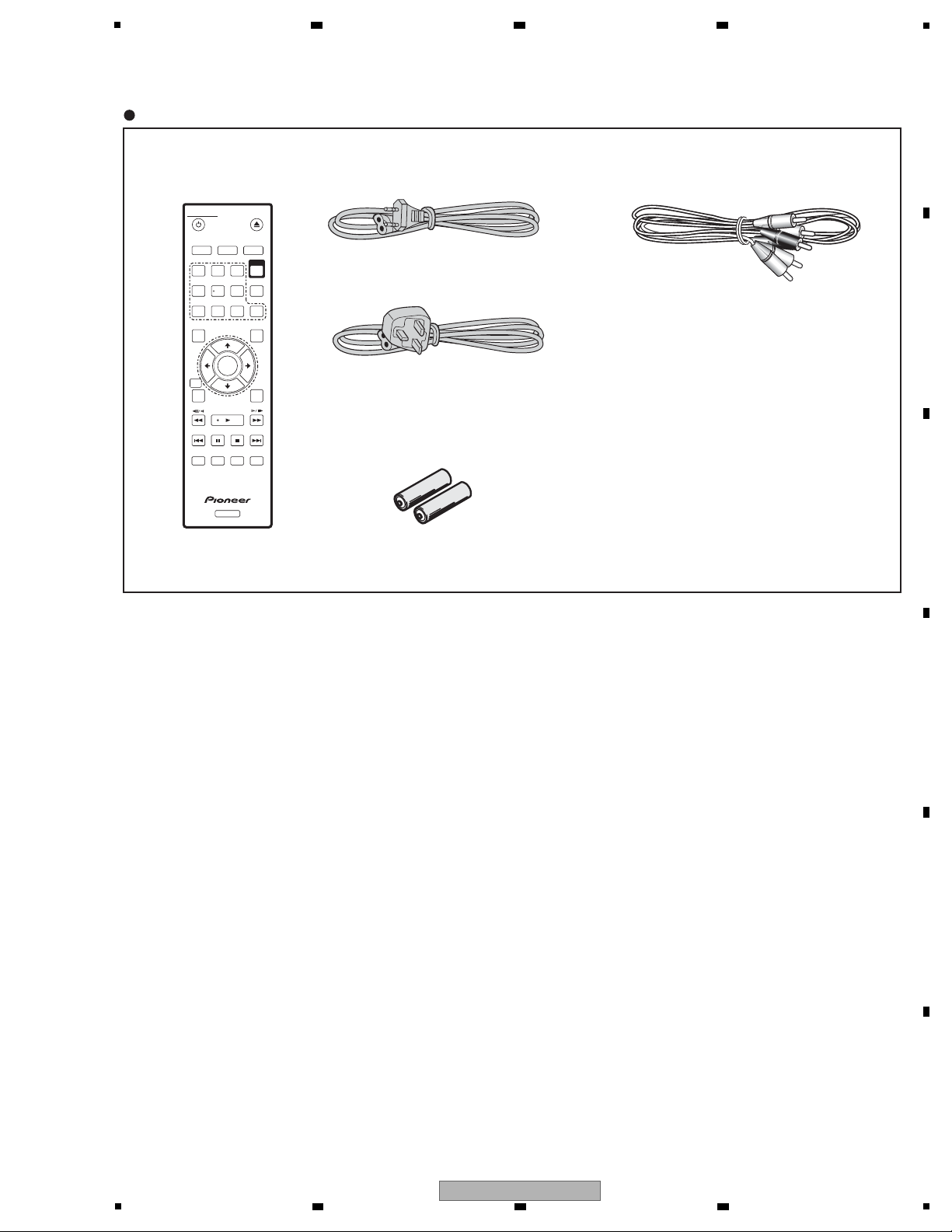
Accessories
• Remote control x1
(076E0PP031:DV-410V-S)
(076E0PP041:DV-410V-K)
• Power cable x1
(1206158802 : WYXZT5, WSXZT5)
• Audio / Video cable(1.2m) x1
(red/white/yellow)
(06CPBA2006)
• Dry cell batteries x2
(AA/R6P)
• Warranty Card
• Operating Instructions
(1206138802 : WVXZT5)
STANDBY/ON
OPEN/CLOSE
AUDIO
SUBTITLE
ANGLE
123
CLEAR
USB
DVD/
4
5
6
7 8 9
0
TOP MENU
MENU
ENTER
RETURN
PLAY MODESURROUND
ZOOM
DISPLAY
PLAY
PREV
PAUSE STOP NEXT
DVD
HOME
MENU
2. SPECIFICATIONS
2.1 ACCESSORIES
6 7 8
A
B
C
D
E
F
DV-410V-S
5
6 7 8
7

1
General
Power requirements. . . . . . . AC 220V to 240V, 50Hz/60Hz
Power consumption
DV-410V . . . . . . . . . . . . . . . . . . . . . . . . . . . . . . . . . . . .11W
Power consumption (standby)
DV-410V . . . . . . . . . . . . . . . . . . . . . . . . . . . . . . . . . . . 0.8W
Weight. . . . . . . . . . . . . . . . . . . . . . . . . . . . . . . . . . . . . 1.7kg
Dimensions
. . . . . . . . . . . . .420mm (W) x 49.5mm (H) x 215mm (D)
Operating temperature . . . . . . . . . . . . . . . . .+5°C to +35°C
Operating humidity . . . . . . . . 5% to 85% (no condensation)
AV Connector
(21-pin connector assignment)
AV connector output . . . . . . . . . . . . . . .21-pin connector
This connector provides the video and audio signals for
connection to a compatible colour TV or monitor.
PIN no.
1. . . . . . . . . . . . . . . . . . . . . . . . . . . . . . . . . . . Audio 2/R out
3. . . . . . . . . . . . . . . . . . . . . . . . . . . . . . . . . . . Audio 1/L out
4. . . . . . . . . . . . . . . . . . . . . . . . . . . . . . . . . . . . . . . . . . GND
7. . . . . . . . . . . . . . . . . . . . . . . . . . . . . . . . . . . . . . . . . .B out
8. . . . . . . . . . . . . . . . . . . . . . . . . . . . . . . . . . . . . . . . . Status
11. . . . . . . . . . . . . . . . . . . . . . . . . . . . . . . . . . . . . . . . .G out
15. . . . . . . . . . . . . . . . . . . . . . . . . . . . . . . . . . . . . . . . .R out
17. . . . . . . . . . . . . . . . . . . . . . . . . . . . . . . . . . . . . . . . . GND
19. . . . . . . . . . . . . . . . . . . . . . . . . . . . . . . . . . . . . Video out
21. . . . . . . . . . . . . . . . . . . . . . . . . . . . . . . . . . . . . . . . . GND
Component video output
P
P
Jack . . . . . . . . . . . . . . . . . . . . . . . . . . . . . . . . . . . . . . . RCA
Video output
Jack . . . . . . . . . . . . . . . . . . . . . . . . . . . . . . . . . . . . . . . RCA
Audio output (1 stereo pair)
Output level. . . . . . . . . . . . . . . . . . . . . During audio output
200mVrms (1kHz, –20dB)
Number of channels. . . . . . . . . . . . . . . . . . . . . . . . . . . . . 2
Jacks . . . . . . . . . . . . . . . . . . . . . . . . . . . . . . . . . . . . . RCA
HDMI output
HDMI output. . . . . . . . . . . . . . . . . . . . . . . . . . . . . . . .19pin
Digital audio characteristics
Frequency response. . . . . . . . . . . . . . . . . . . 4Hz to 44kHz
S/N ratio . . . . . . . . . . . . . . . . . . . . . . . . . . . . . . . . . .115dB
Dynamic range . . . . . . . . . . . . . . . . . . . . . . . . . . . . . .88dB
Total harmonic distortion. . . . . . . . . . . . . . . . . . . .0.0065%
Wow and flutter . . . . . . . . . . . . . . . . Limit of measurement
(±0.001%W. PEAK) or lower
Digital output
Coaxial digital output. . . . . . . . . . . . . . . . . . . . . . . . . . RCA
Accessories
Remote control. . . . . . . . . . . . . . . . . . . . . . . . . . . . . . . . . 1
AA/R6P dry cell batteries. . . . . . . . . . . . . . . . . . . . . . . . . 2
Audio/video cable. . . . . . . . . . . . . . . . . . . . . . . . . . . . . . . 1
Power cable. . . . . . . . . . . . . . . . . . . . . . . . . . . . . . . . . . . 1
Warranty card. . . . . . . . . . . . . . . . . . . . . . . . . . . . . . . . . .1
Operating instructions
The specifications and design of this product are subject
to change without notice, due to improvement.
1 3 5 7 9 11 13 15 17 19 21
2 4 6 8 10 12 14 16 18 20
2.2 SPECIFICATIONS
A
2 3 4
B
C
D
E
F
8
1
2 3 4
DV-410V-S
5
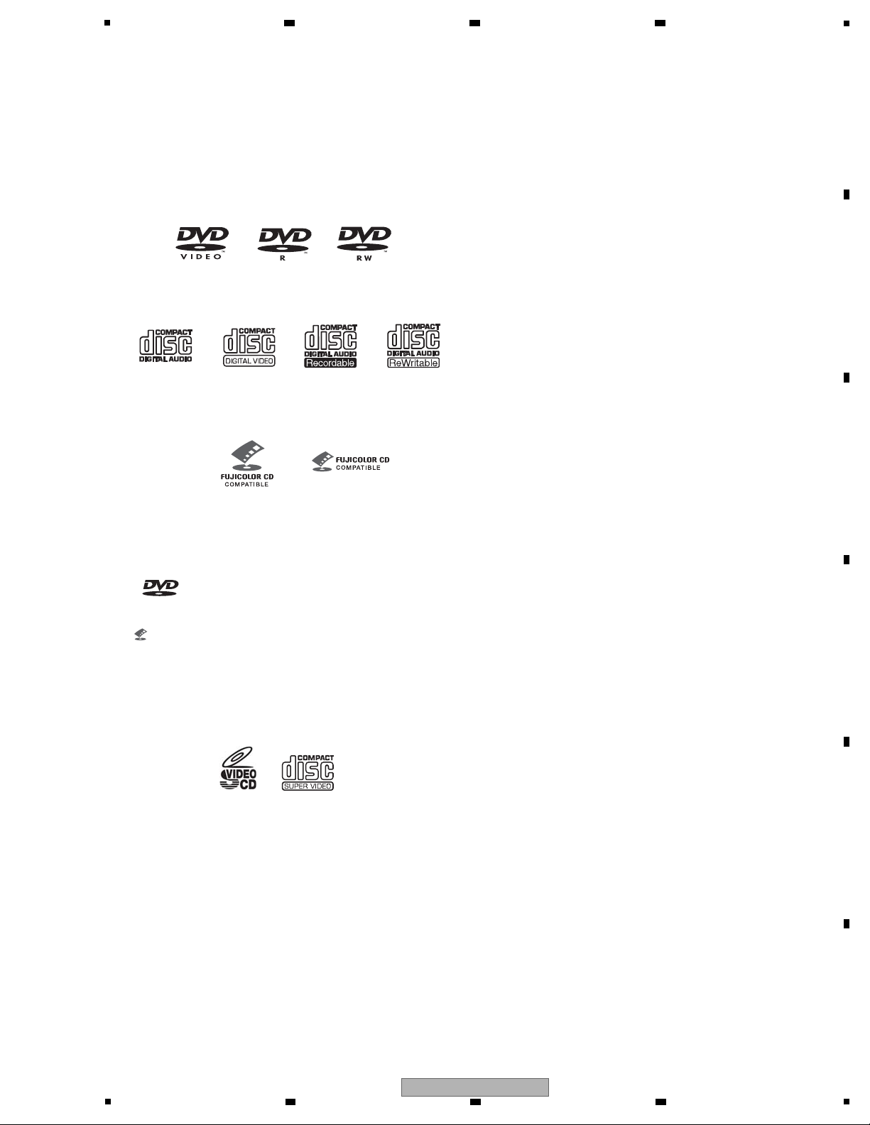
Disc/content format playback compatibility
This player is compatible with a wide range of disc types (media) and
formats. Playable discs will generally feature one of the following
logos on the disc and/or disc packaging. Note however that some
disc types, such as recordable CD and DVD, may be in an
unplayable format—see below for further compatibility information.
Please also note that recordable discs cannot be recorded
using this player.
• This unit will play DVD+R/+RW discs.
• is a trademark of DVD Format/Logo Licensing
Corporation.
• is a trademark of FUJIFILM Corporation.
• Also compatible with KODAK Picture CD
This player supports the IEC’s SuperVCD standard. Compared to
the VideoCD standard, SuperVCD offers superior picture quality,
and allows two stereo soundtracks to be recorded. SuperVCD also
supports the widescreen size.
About DualDisc playback
A DualDisc is a new two -sided disc, one side of which contains DVD
content video, audio, etc. while the other side contains non-DVD
content such as digital audio material.
The non-DVD, audio side of the disc is not compliant with the CD
audio specification and therefore may not play.
The DVD side of a DualDisc plays in this product.
For more detailed information on the DualDisc specification, please
refer to the disc manufacturer or disc retailer.
CD-R/-RW compatibility
• Compatible formats: CD-audio, Video CD/Super VCD, ISO 9660
CD-ROM* containing MP3, WMA, MPEG-4 AAC, JPEG or DivX
video/WMV files
*ISO 9660 Level 1 or 2 compliant. CD physical format: Mode1,
Mode2 XA Form1. Romeo and Joliet file systems are both
compatible with this player.
• Multi-session playback: No
• Unfinalized disc playback: No
• File structure (may differ): Up to299 folders on a disc;
up to 648 folders and files (combined) within each folder
DVD+R/+RW compatibility
Only DVD+R/DVD+RW discs recorded in ‘Video Mode (DVD Video
Mode)’ which have been finalized, can be played back. However,
some editing made during the recording may not be played back
accurately.
DVD-R/-RW compatibility
•Compatible formats: DVD-Video, Video Recording (VR)*
* Edit points may not play exactly as edited; screen may go
momentarily blank at edited points.
•Unfinalized playback: No
•MP3/WMA/MPEG-4 AAC/JPEG or DivX video/WMV file playback
on DVD-R/-RW: Yes
Compressed audio compatibility
•Compatible formats: MPEG-1Audio Layer 3 (MP3), Windows
Media Audio (WMA), MPEG-4 AAC
•Sampling rates: 32kHz, 44.1kHz or 48kHz
•Bit-rates: Any (128 kbps or higher recommended)
•VBR (variable bit rate) MP3/WMA/MPEG-4 AAC playback: No
•WMA lossless encoding compatible: No
•DRM (Digital Rights Management) compatible: No (DRMprotected audio files will not play in this player
•File extensions: .mp3, .wma, .m4a (these must be used for the
player to recognize MP3, WMA and MPEG-4 AAC files–do not
use for other file types)
Audio CD Video CD CD-R CD-RW
DVD-Video DVD-R DVD-RW
Fujicolor CD
Super VCD
2.3 DISC/CONTENT FORMAT
6 7 8
A
B
C
D
E
F
DV-410V-S
5
6 7 8
9

1
About MPEG-4 AAC
Advanced Audio Coding (AAC) is at the core of the MPEG-4 AAC
standard, which incorporates MPEG-2 AAC, forming the basis of the
MPEG-4 audio compression technology. The file format and
extension used depend on the application used to encode the AAC
file. This unit plays back AAC files encoded by iTunes
®
bearing the
extension ‘.
m4a
’. DRM-protected files will not play, and files
encoded with some versions of iTunes
®
may not play, or filenames
may display incorrectly.
Apple and iTunes
®
are trademarks of Apple Inc., registered in the
U.S. and other countries.
WMA (Windows Media™ Audio) compatibility
This player can playback Windows Media Audio content.
WMA is an acronym for Windows Media Audio and refers to an
audio compression technology developed by Microsoft Corporation.
WMA content can be encoded by using Windows Media Player for
Windows XP, Windows Media Player 9 or Windows Media Player 10
series.
•Windows Media is a trademark of Microsoft Corporation.
•This product includes technology owned by Microsoft Corporation
and cannot be used or distributed without a license from
Microsoft Licensing, Inc.
About DivX video
DivX is a digital videoformat created by DivX, Inc. This player can
play DiviX videos burned on CD-R/-RW/-ROM discs. Keeping the
same terminology as DVD-Video, individual DivX video files are
called “Titles”. When naming files/titles on a CD-R/-RW disc prior to
burning, keep in mind that by default they will be played in
alphabetical order.
DivX video compatibility
•Official DivX Ultra Certified product.
®
•Plays all versions of DivX video (including DivX 6) with
®
®
standard playback of DivX media files.
®
•File extensions: .avi and .divx (these must be used for the player
to recognize DivX video files).Note that all files with the .avi
extension are recognized as MPEG4, but not all of these are
necessarily DivX video files and therefore may not be playable
on
this player.
About WMV
WMV is an acronym for Windows Media Video and refers to a video
compression technology developed by Microsoft Corporation. WMV
content can be encoded by using Windows Media Encoder.
®
•This player is compatible with WMV9 files that are encoded by
using the Windows Media Encoder 9 Series, with .wmv as an
®
extension.
•Compatible with size under 720 x 480 pixels/720 x 576 pixels.
•Advanced Profile is not supported.
•DRM-protected video files will not play in this player.
JPEG file compatibility
•Compatible formats: Baseline JPEG and EXIF 2.2* still image
files up to a resolution of 3072 x 2048.
* File format used by digital still cameras.
•Progressive JPEG compatible: No
•File extensions: .jpg (must be used for the player to recognize
JPEG files–do not use for other file types)
PC-created disc compatibility
Discs recorded using a personal computer may not be playable in
this unit due to the setting of the application software used to create
the disc. In these particular instances, check with the software
publisher for more detailed information.
Discs recorded in packet write mode (UDF format) are not
compatible with this player.
Check the DVD-R/-RW or CD-R/-RW software disc boxes for
additional compatibility information.
TM
A
2 3 4
B
C
D
E
F
10
1
2 3 4
DV-410V-S
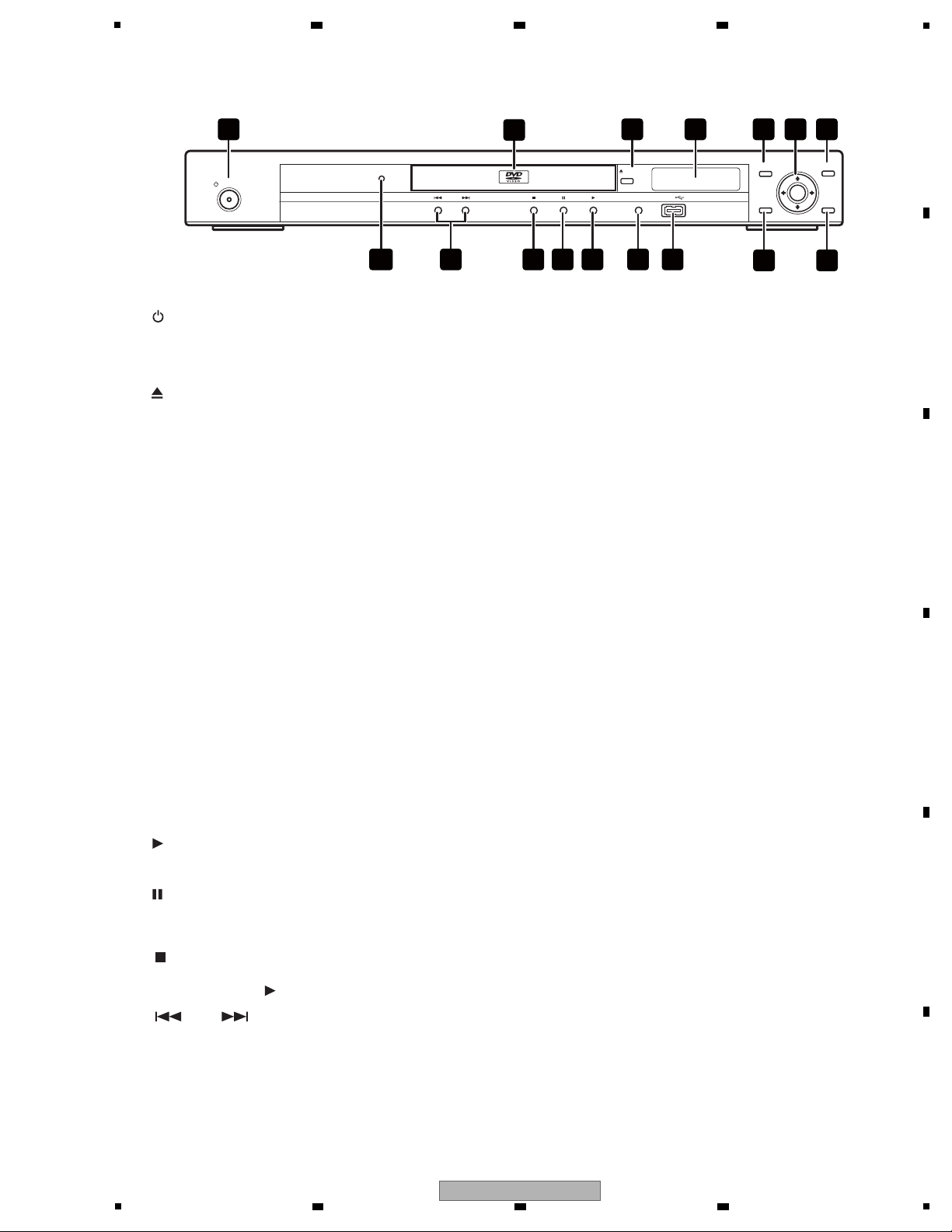
Front panel
1
2 Disc tray
STANDBY/ON
3
4 Display
5 TOP MENU
6 ENTER & cursor buttons
7 MENU
8 RETURN
9 HOME MENU
10 USB port (Type A)
11 DVD/USB
and
12
13
14
Lights when this player is recognized by
another HDMl or DVI/HDCP compatible
component.
15
16 HDMI indicator
Press to switch the player on or into standby.
Press to pause playback. Press again to
restart.
Press to start or resume playback.
Press to stop the disc (you can resume playback by pressing
(play)).
Press to open or close the disc tray.
Displays a DVD disc (or DiviX media files) menu
—this varies with the disc and may be the same
as the ‘top menu’.
Selects the current menu option.
Returns to the previously displayed menu screen.
Display/exit the on-screen display.
Press to turn to USB mode and return to DVD mode.
Skips to the start of the current track, title or
chapter, then to previous tracks/titles/chapters.
Skips to the next track, title or chapter.
Displays the ‘top menu’ of a DVD disc
—this varies with the disc.
OPEN/CLOSE
HDMI
HOME
MENU
RETURN
ENTER
TOP MENU MENU
USBDVD/USB
STANDBY/ON
2
53 4 6 71
9 8
1012 1116 131415
DV-410V
OPEN/CLOSE
5
2.4 PANEL FACILITILES
6 7 8
A
B
C
5
DV-410V-S
6 7 8
D
E
F
11

1
Remote control
Press to switch the player on or into standby.
Press to select the audio channel or language.
Press to select a subtitle option.
Press to display the top menu of a DVD disc.
Use to navigate on-screen displays and
menus. Press
ENTER to select an option or
execute a command.
Use for reverse slow motion playback, frame
reverse and reverse scanning.
Press to start or resume playback.
Press to display the Play Mode menu. (You
can also get to the Play Mode menu by
pressing
HOME MENU and selecting Play
Mode).
Press to jump to the beginning of the current
Press to switch on/off virtural Surround.
Display/exit the on-screen display.
Press to open or close the disc tray.
Press to change the camera angle during
DVD multi-angle scene playback.
Press to clear a numeric entry.
Press to turn to USB mode and return to DVD
mode.
Skips to the start of the current track, title or
chapter, then to previous tracks/titles/chapters.
Press to pause playback; press again to
restart.
Displays a DVD disc (or DiviX media files) menu
—this varies with the disc and may be the same
as the ‘top menu’.
2AUDIO
3 SUBTITLE
4 Number buttons
5TOP MENU
6 ENTER & cursor buttons
7HOMEMENU
and
12 SURROUND
13 PLAY MODE
15 ANGLE
16 DVD/USB
17 CLEAR
18 MENU
19 RETURN
23 DISPLAY
24 ZOOM
STANDBY/ON
OPEN/CLOSE
AUDIO
SUBTITLE
ANGLE
123
CLEAR
USB
DVD/
4 5 6
7 8 9
0
TOP MENU MENU
ENTER
RETURN
PLAY MODESURROUND
ZOOM
DISPLAY
PLAY
PREV
PAUSE STOP NEXT
DVD
HOME
MENU
1
23
21
20
19
18
17
16
15
14
2
4
5
6
7
8
10
12
13
3
9
2211
24
Press to return to a previous menu screen.
Use for forward slow motion playback, frame
advance and forward scanning.
Press to jump to the next chapter or track.
Press to display information about the disc
playing.
Press to change the zoom level.
A
2 3 4
B
C
D
E
F
12
1
DV-410V-S
2 3 4

5
Check points after servicing (DVD player)
To keep the product quality after servicing, confirm recommended check points shown below.
See the table below for the items to be checked regarding video and audio:
Cleaning
• Before shipping out the product, be sure to clean the following positions by using the prescribed cleaning tools:
Pickup lenses Cleaning liquid : GEM1004
Cleaning paper : GED-008
Position to be cleaned Cleaning tools Position to be cleaned Cleaning tools RemarkRemark Position to be cleaned Cleaning tools Remark
No. Procedure Check points
1 Confirm the firmware version on Service Mode. The version of the firmware must be latest.
Update firmware to the latest one, if it is not the latest.
The customer complain must not be reappeared.
Video, audio and operations must be normal.
2
Confirm whether the customer complain has been solved.
If the customer complain occurs with the specific disc,
use it for the operation check.
The error rates must be less than 5.0e-4.
3
Confirm playback error rates at the innermost and
outermost tracks by using the following disc.
DVD test disc (GGV1025)
4
Play back a DVD.
(Menu operation, Title/chapter search)
Audio and operations must be normal.
5
Play back a DVD.
(Menu operation, Title/chapter search)
Video, audio and operations must be normal.
6
Check the appearance of the product. No scratches or dirt on its appearance after receiving it
for service.
Items to be checked regarding video Item to be checked regarding audio
Block noise Distortion
Horizontal noise Noise
Dot noise Volume too low
Disturbed image (video jumpiness) Volume too high
Too dark Volume fluctuating
Too bright Sound interrupted
Mottled color
6 7 8
3. BASIC ITEMS FOR SERVICE
3.1 CHECK POINTS AFTER SERVICING
A
B
C
D
E
F
DV-410V-S
5
6 7 8
13
1
OPERATION PCB ASSY
POWER PCB ASSY
DVD MT PCB ASSY
DVD MECHA ASSY
3.2 PCB LOCATIONS
A
B
2 3 4
C
D
Mark No. Description Part No.
LIST OF ASSEMBLIES
1..DVD MT PCB ASSY A2L302A130
E
1..OPERATION PCB ASSY A2L302A270
> 1..POWER PCB ASSY A2L302A240
1..DVD MECHA ASSY A2L101A650
F
14
1
2 3 4
DV-410V-S

5
Service Remote Control Unit GGF1381 diagnosis
Name Jig No. Remarks
DVD Test Disc (DVD-
Video,NTSC)
GGV1025 Operation Check
DVD Test Disc (DVD-Video,PAL)
CD Test Disc
GGV1101
STD-905
Operation Check
Operation Check
Jigs list
Lubricants and Glues list
Daifree GEM1036 (ZLX-ME413A) Refer to «9.3 DVD MECHA SECTION»
Grease GYA1001 (ZLB-PN397B) Refer to «9.3 DVD MECHA SECTION»
Grease GEM1018 Refer to «9.3 DVD MECHA SECTION»
Name Lubricants and Glues No. RemarkName Lubricants and Glues No. RemarkName Lubricants and Glues No. Remark
6 7 8
3.3 JIGS LIST
A
B
C
D
E
F
DV-410V-S
5
6 7 8
15
1
3
2
1
CP603
3
2
1
CP604
432
1
CP602
USB CONNECTOR
432
1
CP605
432
1
CP4004
11
10
987654321
11
10
987654321
12
11
10
9
8
7
6
5
4
3
2
1
12
11
10
9
8
7
6
5
4
3
2
1
2
1
16
15
14
13
12
11
10
9
8
7
6
5
4
3
2
1
16
15
14
13
12
11
10
9
8
7
6
5
4
3
NOTE:THE DC VOLTAGE AT EACH PART WAS MEASURED
WITH THE DIGITAL TESTER WHEN THE COLOR BROADCAST
WAS RECEIVED IN GOOD CONDITION AND PICTURE IS NORMAL.
Vout
B+
GND
OS651
123
J8101
21PIN CONNECTOR
1
10
11
12
13
14
15
16
17
18
19
220
21 3
4
5
6
7
8
9
J501
AC INLET
12
CD501_2
AC220V-240V_50Hz/60Hz(EU)
CP5901
HDMI CONNECTOR
1
10
11
12
13
14
15
16
17
18
19
2
3
4
5
6
7
8
9
H1H2EH1H2
E
J7302
CVBS/Y/U/V
1
23
4
56
H1 H2
E
J8001
L/R
1
2 3
H
E
J8003
COAXIAL for
1
2
DEG149
PCB270
OPERATION PCB
PCB271
OPERATION2 PCB
CP502
NC
NC
NC
NC
NC
NC
CP7301CP503
DEG150
POWER
SW2
GND
3
2
1
3
2
1
CD7301
3
2
12
11
10
9
8
7
6
5
4
1
12
11
10
9
8
7
6
3
2
5
4
1
CP4002
10
3
2
98765
4
1
CD601
DGND
FLDC+
-28V
V+3E
IR
STB
DO (F to M)
DI (M to F)
CLK
DGND
P.ON-H(STBY L)
P.CON+12V
P.CON+5V
GND
GND
P.CON+6V
GND(M)
AT+3.3V
AT+3.3V
CP4003_1
CD605
432
1
432
1
3
2
98765
4
1
11
10
11
TM101
COMMAND TRANSMITTER
NC
POWER
SW2
GND
+5V
GND
USB_DN
USB_DP
CP601
USBN
USBP
USB+5V
GND(USB)
USBN
USB+5V
GND(USB)
USBP
DGND
FLDC+
-28V
FLDC-
V+3E
IR
STB
DO (F to M)
DI (M to F)
CLK
DGND
FLDC-
FL DCFL DC+
-28V
GND(D)
GND(USB)
USB+5V
RGB-H
R
B
G
GND
CVBS
AUDIO R
GND
AUDIO L
FS
GND
GND
D2+
D2-S
D2-
D1+
D1-S
D0+
D0-S
D0-
CLK-S
CLK-
CEC
SCL
SDA
GND
POWER
HOTPLUG
NC
D1-
CLK+
VIDEO/AUDIO for 21PIN
3
2
9
8
7
6
5
4
1
10
DPG017
PCB240
POWER PCB
P.ON-H(STBY L)
P.CON+12V
P.CON+5V
FL DCFL DC+
GND
GND
P.CON+6V
-28V
GND(M)
GND(D)
AT+3.3V
AT+3.3V
GND(USB)
USB+5V
GND
AUDIO L
GND
AUDIO R
RGB-H
CVBS
FS
G
B
R
GND
GND
CD502
16
15
14
13
12
11
16
15
3
2
9
8
7
6
5
4
1
14
13
12
11
10
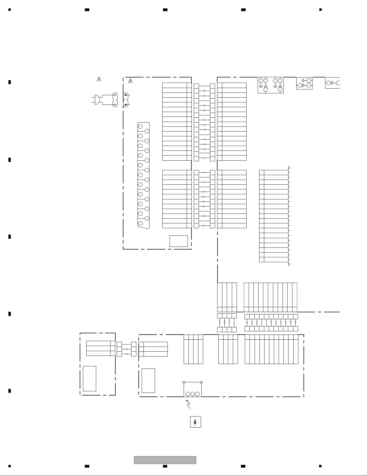
DVD MT PCB ASSY
(1/7 — 7/7)
(A2L302A130)
OPERATION
PCB ASSY
(A2L302A270)
POWER PCB ASSY
(1/2,2/2)
(A2L302A240)
2 3 4
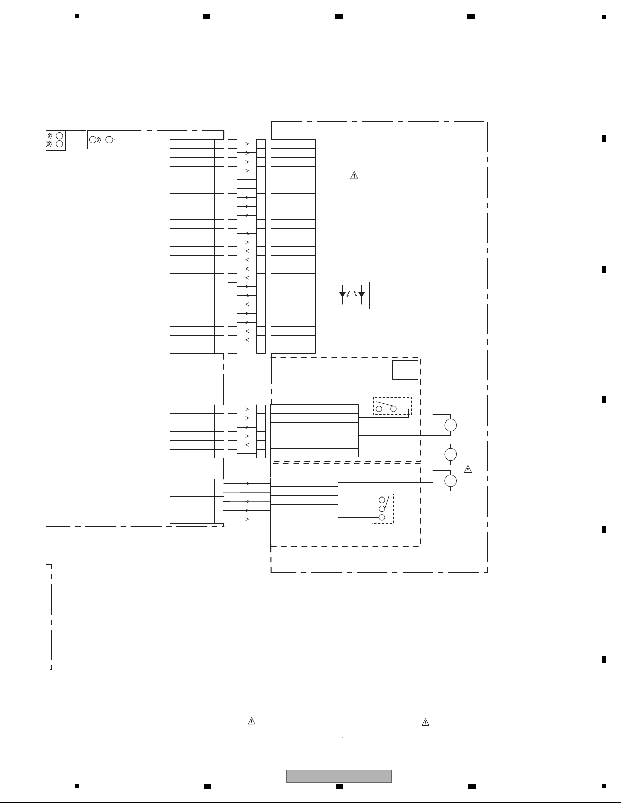
4. BLOCK DIAGRAM
4.1 OVERALL WIRING DIAGRAM
A
B
C
D
E
F
16
1
2 3 4
DV-410V-S
5
5
4
3
2
1
CP2302
6
5
4
3
2
1
CP2303
24
23
22
21
20
19
2
1
18
17
16
15
14
13
12
11
10
9
8
7
6
5
4
3
CP2301
VRCOM
TRKG DRV
TRKG RTN
FOCS RTN
FOCS DRV
VCC
D
B
VR780(CD)
VRF(RF_OUT)
SW1(DVD/CD)
C
E
VS
F
GND
A
VR650(DVD)
GND
GND
LD_DVD(650)
LD_CD(780)
PD/GND
NC
SW(GND)
LIMIT SW
SLD-
SLD+
SPD-
SPD+
LOAD+
LOAD-
GND
OPEN
CLOSE
24
23
22
21
20
19
18
17
16
15
14
13
12
11
10
9
8
7
6
5
4
3
2
1
24
23
22
21
20
19
18
17
16
15
14
13
12
11
10
9
8
7
6
5
4
3
2
1
6
5
4
3
2
1
6
5
4
3
2
1
B
A
VRCOM
VR780(CD)
VRF(RF_OUT)
SW1(DVD/CD)
C
VR650(DVD)
GND
LD_DVD(650)
LD_CD(780)
PD/GND
TRKG DRV
TRKG R
T
N
FOCS RTN
FOCS DRV
VCC
D
E
VS
F
GND
GND
NC
DM-4PB
DRIVE
DVD
OPTICAL PICK-UP
DED021
PCB610
CD2302
BCZ3B05
M2603
M
5
4
3
2
1
SW-2(CLOSE)
GND(SW)
SW-1(OPEN)
LOADING MOTOR(-)
LOADING MOTOR(-)
2H051602
SSS-28-5
SW1
BCZ3B05
JCV9B12
M2601
M2602
ESE22MH22
SW2
M
M
2H061605
CD2301
DED020
PCB640
SPINDLE MOTOR(+)
SPINDLE MOTOR(-)
FEED MOTOR(-)
GND(SW)
FEED MOTOR(+)
PICK UO INNER LIMIT SWITCH
6
5
4
3
2
1
D
NORMAL.
:LES PIECES REPAREES PAR UN ETANT
DANGEREUSES AN POINT DE VUE SECURITE
N’UTILISER QUE CELLS DECRITES
DANS LA NOMENCLATURE DES PIECES
ATTENTION
:SINCE THESE PARTS MARKED BY ARE
CRITICAL FOR SAFETY,USE ONES
DESCRIBED IN PARTS LIST ONLY
CAUTION
H1 H2
L/R
1
2 3
H
E
J8003
COAXIAL for ME
1
2
CD601
CP601
DVD MECHA ASSY
(A2L101A650)
(SW PCB)
(LOADING MOTOR PCB)
6 7 8
A
B
C
D
E
5
6 7 8
DV-410V-S
F
17

1
P. C O N+12V
AC220~240V
FLDC+/-
X4001
27MHz
-28V
AT+ 1 2 V for mute
AT+3.3V
P. C O N+6V
P. C O N+5V
POWER
SUPPLY
DVD
LOADER
(DM4)
MOTOR DRIVER
IC2301
AM5766
FIP DRIVER IC
IC651
PT6315
EEPROM
IC4001
S-24CS04AFJ-TB-
GE
AUDIO AMP IC
IC8008
RC4580IDR
FIP
HNV-08SS44T
KEY
SERVO
RF
SERVO
IR
FP,STB
ASPDIF
RESET
AUDIO_L,
AUDI O_R
AMP_AUDIO_L/R
LD_DVD,
LD_CD
IR
108MHz
TV Encoder
MPEG-1/2/
JPEG
VIDEO
DECORDER
R
COAXIAL
RF
CO
L
OVERALL BLOCK DIAGRAM
IR RECEIVER
(OS651)
ROM-V340TAO
16Mbit FLASH
IC4004
ES29LV160EB-70TG
64Mbit(4M*16) 166MHz
SDRAM
IC4005
M12L64164A-5TG
V+3,
SDA,
SCL
AMUTE
MPEG/MICON
IC4002
MT1389FE/S-L
AUDIO CODEC/
INTERNAL DAC
+1.8V
A0~A20,
AD0~AD7
MA0~MA11,
DQ0~DQ15
RESET IC
IC4003
R3112N291A-
TR-FA
VIDEO DRIVER 6CH IC
IC7301
LA73054-TLM-E
4CH VIDEO DAC
V
U
Y
4CH BUS SW IC
IC7302
SN74CBT3257PWR
21PIN
RGB OUT
CVBS
2 3 4
4.2 OVERALL BLOCK DIAGRAM
A
B
C
D
E
F
18
1
2 3 4
DV-410V-S

5
DVD LOADER/MPEG BLOCK DIAGRAM
DVD
Loader
(DM-4)
MPEG/MICON IC
IC4002
MT1389FE/S-L
X4001
27MHz
IOA, V20
C
RF, A, B, C, D, E, F, MDI1
LD_DVD, LD_CD
Q2302~2305
LD DRIVE
LDO1, LDO2
MOTOR DRIVE IC
IC2301
AM5766
DMSO, FMSO,
TROPEN, TRCLOSE,
TRSO, FMSO,
STBY, V1P4
T+/-, F+/-,
LOAD+/-,
MOT_SLED+/-,
MOT_SPDL+/-
OPU
SPINDLE/
STEPING/
SLED
MOTOR
LIMIT, TRIN, TROUT,
OPO, OP+/-
AUDIO AMP IC
IC8008
RC4580IDR
A
D
A0~A20, AD0~AD7,
PRD#, PCE#, PWR#
3
2
R
L
AUDIO JACK L/R
J8001
AUDI O R
AUDI O L
AUDIO L, R
F
A…….AT+3.3V
B…….+1.8V
C…….P.CON+5V
D…….P.CON+6V
E…….AT+12V
F…….P.CON+12V
G…….-28V
H…….V+5H
RESET IC
IC4003
R3112N291A-TR-FA
A
RESET
ASPDIF
2
COAXIAL JACK
J8003
VIDEO DRIVER 6CH IC
IC7301
LA73054-TLM-E
LETTER, I/XP,
R/CR, B/CB, G/Y, CVBS
C
A, B
GR1~GR8, P1~P16
FP_DI, FP_DO,
FP_SCK, STB
3
5
Y
U
CVBS/Y/U/V
J7302
2
V
FIP (V651)
HNV-08SS84
G
19
CVBS
21PIN CONNECTOR
J8101
11
15
R OUT
G OUT
16
7
B OUT
3
L
4CH BUS SW IC
IC7302
SN74CBT3257PWR
C
SQUEEZE, VSEL1
VSEL1
6
CVBS
CR OUT
Y2 OUT
CB OUT
1
R
8
VSEL1
SQUEEZE
21 PIN CTL
BLANKING_OUT
Q8104, Q8105
DVD_RGB_H_OUT
D2+
1
3
D1+
4
D1-
6
D0+7D0-
9
CLK+
10
D2-
HDMI CONNECTOR
CP5901
MA0~MA11, DQ0~DQ15,
DQM0, DQM1, DBA0, DBA1,
SDCLK, SDCKE, DWE#,
DRAS#, DCAS#, DCS#
CLK-
12
HDMI_SCL
HDMI_SDA
16Mbit FLASH
IC4004
ES29LV160EB-70TG
A
64Mbit SDRAM
IC4005
M12L64164A-5TG
A
EEPROM IC
IC4001
S-24CS04AFJ-TB-GE
SCL
A
SDA
IR
IR RECEIVER (OS651)
KSM-2001TC2P
IR
A
FIP DRIVER IC
IC651
PT6315
A
HOTPLUG
19
POWER
18
SDA
16
15
SCL
USBN
HIGH SIDE SW
IC4007
R5523N001B-TR-F
USB_FLAG
USB_P_ON-L
4
3
CP4004
USBP
Q8101, Q8102
21 PIN CTL
Q5906
SW
L5901
342
1
6
5
7
8
L5902
342
1
6
5
7
8
6 7 8
4.3 DVD LOADER/MPEG BLOCK DIAGRAM
A
B
C
D
E
5
F
DV-410V-S
19
6 7 8

1
SWITCHING
TRANS
T501
P. C O N SW
POWER BLOCK DIAGRAM
Q505
AC IN
P.CON+5V
AT+3.3V
FL DC —
-28V
AT +1 2 V for mute
P.CON+6V
P.CON+12V
P. O N-H
FL DC +
Q515
P. C O N +5V REG
Q510
P. C O N +12V SW
Q504
FL+ P.CON SW
Q502
-28V P. C O N SW
VOLTAGE CTL
IC501
KIA431A-AT
PHOTO COUPLER
IC504
PS2561AL1-1-V(W)
POWER CTL
IC502
STR-A6159M
6V REG
(DVD MOTOR)
IC503
PQ070XF01SZH
REG+1.8V
IC4006
LD1117AL-ADJ-AA3-A-F
+1.8V
HDMI+5V REG
IC5902
PQ1K503M2ZPH
V+5H
4.4 POWER BLOCK DIAGRAM
A
2 3 4
B
C
D
1
DV-410V-S
2 3 4
E
F
20

5
POWER DOES NOT TURN ON
Is the voltage at
pin 8 and pin 9 of CP502 about 3.3V
and at pin 5 of CP502
about 5V?
No
Ye s
No
Is there waveform at
X4001 about 3.0Vp-p ?
Check X4001, IC4002 and
peripheral circuit.
Ye s
Write DVD FIRMWARE DATA.
Check AT+3.3V line of POWER BLOCK.
Check Q515 and peripheral circuit.
No
Ye s
No
DECK DOES NOT ACCEPT
OPEN/CLOSE
Check P.CON 6V line of
POWER BLOCK.
Ye s
Is the lose connection
at CD2302 to DECK ?
Check CD2302
connection to DECK.
Change DVD LOADER.
Is the voltage at
pin 8 and 19 of IC2301
about DC6V ?
5. DIAGNOSIS
5.1 TROUBLE SHOOTING
6 7 8
A
B
C
D
E
DV-410V-S
5
6 7 8
F
21

1
DOES NOT LIGHT ON DISPLAY
Ye s
Is the voltage at
pin 13 and pin 43 of IC651
about 3V ?
Check AT+3.3V line of
POWER BLOCK.
No
Replace V651 or IC651.
NO PLAYBACK PICTURE OF AV
JACK
Is there
video signal at pin 33
of IC7301 ?
Change IC7301.
No
Ye s
No
Ye s
Check J7302 and peripheral
circuit.
Is there
a signal at pin 187 of
IC4002 ?
Check IC4002 and
peripheral circuit.
A
B
2 3 4
C
D
E
F
22
1
2 3 4
DV-410V-S
Loading…
Перейти к контенту
DVD-плееры Pioneer
- Размер инструкции: 2.98 Мб
- Формат файла: pdf
Если вы потеряли инструкцию от dvd-плеера Pioneer DV-410 V K, можете скачать файл для просмотра на компьютере или печати.
Инструкция для dvd-плеера Pioneer DV-410 V K на русском языке. В руководстве описаны возможности и полезные функции, а также правила эксплуатации. Перед использованием внимательно ознакомьтесь с инструкцией.
Чтобы не читать всю инструкцию вы можете выполнить поиск по содержимому внутри инструкции и быстро найти необходимую информацию. Рекомендации по использованию помогут увеличить срок службы dvd-плеера Pioneer DV-410 V K. Если у вас появилась проблема, то найдите раздел с описанием неисправностей и способами их решения. В нем указаны типичные поломки и способы их решения.
Manual
View the manual for the Pioneer DV-410V-K here, for free. This manual comes under the category DVD players and has been rated by 3 people with an average of a 8.5. This manual is available in the following languages: English. Do you have a question about the Pioneer DV-410V-K or do you need help?
Ask your question here
Pioneer DV-410V-K specifications
Below you will find the product specifications and the manual specifications of the Pioneer DV-410V-K.
Analog signal format system
NTSC, PAL
Video formats supported
DivX, WMV
Audio D/A Converter (DAC)
24-bit/96kHz
Disc types supported
CD, DVD-R DL
Digital audio coaxial out
1
General
| Brand | Pioneer |
| Model | DV-410V-K | DV-410V-K |
| Product | DVD player |
| EAN | 0012562893433, 0796037826675, 4977729893489 |
| Language | English |
| Filetype | User manual (PDF) |
Video
| Analog signal format system | NTSC, PAL |
| Video D/A Converter (DAC) | 12-bit/108MHz |
File formats
| Video formats supported | DivX, WMV |
| Audio formats supported | MP3, WMA |
Audio
| Audio D/A Converter (DAC) | 24-bit/96kHz |
| Signal-to-Noise Ratio (SNR) | 115 dB |
| Total Harmonic Distortion (THD) | 0.0065 % |
| Frequency range | 4 — 44000 Hz |
Technical details
| Device type | DVD player |
| Product colour | Black |
Storage
| Disc types supported | CD, DVD-R DL |
Ports & interfaces
| Digital audio coaxial out | 1 |
| Component video (YPbPr/YCbCr) out | 1 |
| SCART ports quantity | 1 |
| USB 2.0 ports quantity | 1 |
| HDMI ports quantity | 1 |
Packaging content
| Remote control included | Yes |
Other features
| Power requirements | AC 220 — 240V, 50/60 Hz |
Power
| Power consumption (standby) | 0.8 W |
| Power consumption (typical) | 11 W |
Weight & dimensions
| Weight | 1700 g |
| Depth | 215 mm |
| Height | 49.5 mm |
| Width | 420 mm |
show more
Frequently Asked Questions
Can’t find the answer to your question in the manual? You may find the answer to your question in the FAQs about the Pioneer DV-410V-K below.
What is the weight of the Pioneer DV-410V-K?
The Pioneer DV-410V-K has a weight of 1700 g.
What is the height of the Pioneer DV-410V-K?
The Pioneer DV-410V-K has a height of 49.5 mm.
What is the width of the Pioneer DV-410V-K?
The Pioneer DV-410V-K has a width of 420 mm.
What is the depth of the Pioneer DV-410V-K?
The Pioneer DV-410V-K has a depth of 215 mm.
How can I best clean my DVD player?
A slightly damp cleaning cloth or soft, dust-free cloth works best to remove fingerprints. Dust in hard-to-reach places is best removed with compressed air.
Is the manual of the Pioneer DV-410V-K available in English?
Yes, the manual of the Pioneer DV-410V-K is available in English .
Is your question not listed? Ask your question here
Инструкция и руководство для
Pioneer DV-410V-S
42 страницы подробных инструкций и пользовательских руководств по эксплуатации на русском
00:45
Домашний_кинотеатр_Pioneer_DCS_360_baraholka_rasprodaga_lugansk
07:24
ОБЗОР -pioneer DVD player DV-120k
13:37
не большой обзор cd dvd usb проигрывателя Pioneer Dv-420
01:39
Pioneer DV-410V DVD Player
11:06
Pionneer DVD Player DV-410V เครื่องเล่นดีวีดีไพโอเนียร์ สภาพสวยพร้อมรีโมท
04:59
Tonsil MAESTRO S, Denon DRA-435R, Pioneer DV-410V [N-STUDiO]
13:35
PIONEER DVD PLAYER DV-410V เครื่องเล่นดีวีดีไพโอเนียร์ รุ่น DV-410V ขายเครื่องเล่นดีวีดีไพโอเนียร์
Нажмите на кнопку для помощи
Комментарии не найденыНе стесняйтесь поделиться с нами вашим ценным мнением.
Ваш комментарий добавлен. Обновите страницу.
- Topics
- manualsbase, manuals,
- Collection
- manuals_pioneer; manuals; additional_collections
- Language
- English
- Item Size
- 20.5M
- Addeddate
- 2020-07-29 07:04:36
- Identifier
- manualsbase-id-129470
- Identifier-ark
- ark:/13960/t9s27078r
- Ocr
- ABBYY FineReader 11.0 (Extended OCR)
- Ppi
- 300
- Scanner
- Internet Archive Python library 1.9.3
plus-circle Add Review
plus-circle Add Review
comment
Reviews
There are no reviews yet. Be the first one to
write a review.
94
Views
DOWNLOAD OPTIONS
download 1 file
ABBYY GZ download
Temporarily Unavailable
DAISY
For users with print-disabilities
Temporarily Unavailable
EPUB
download 1 file
FULL TEXT download
download 1 file
ITEM TILE download
download 1 file
PAGE NUMBERS JSON download
download 1 file
PDF download
download 1 file
SINGLE PAGE PROCESSED JP2 ZIP download
download 1 file
TORRENT download
download 12 Files
download 6 Original
SHOW ALL
IN COLLECTIONS
Manuals: Pioneer
The Manual Library
Additional Collections
Uploaded by
chris85
on