

AUDIO/VIDEO MULTI-CHANNEL RECEIVER
RECEPTOR MULTICANAL DE AUDIO/VÍDEO
VSX-1020
Register your product on
http://www.pioneerelectronics.com (US)
http://www.pioneerelectronics.ca (Canada)
·
Protect your new investment
The details of your purchase will be on file for reference in the event of an
insurance claim such as loss or theft.
·
Receive free tips, updates and service bulletins on
your new product
·
Improve product development
Your input helps us continue to design products that meet your needs.
·
Receive a free Pioneer newsletter
Registered customers can opt in to receive a monthly newsletter.
Operating Instructions
Manual de instrucciones

WARNING
This equipment is not waterproof. To prevent a fire or
shock hazard, do not place any container filled with
liquid near this equipment (such as a vase or flower
pot) or expose it to dripping, splashing, rain or
moisture.
D3-4-2-1-3_A1_En
WARNING
Before plugging in for the first time, read the following
section carefully.
The voltage of the available power supply differs
according to country or region. Be sure that the
power supply voltage of the area where this unit
will be used meets the required voltage (e.g., 230 V
or 120 V) written on the rear panel.
This product is for general household purposes. Any
failure due to use for other than household purposes
(such as long-term use for business purposes in a
restaurant or use in a car or ship) and which requires
repair will be charged for even during the warranty
period.
IMPORTANT NOTICE
THE MODEL NUMBER AND SERIAL NUMBER OF
THIS EQUIPMENT ARE ON THE REAR OR BOTTOM.
RECORD THESE NUMBERS ON YOUR ENCLOSED
WARRANTY CARD AND KEEP IN A SAFE PLACE
FOR FUTURE REFERENCE.
This Class B digital apparatus complies with
Canadian ICES-003.
D3-4-2-1-4*_A1_En
K041_A1_En
D36-AP9-1_A1_En
D8-10-1-3_A1_En
If the AC plug of this unit does not match the AC
outlet you want to use, the plug must be removed
and appropriate one fitted. Replacement and
mounting of an AC plug on the power supply cord of
this unit should be performed only by qualified
service personnel. If connected to an AC outlet, the
cut-off plug can cause severe electrical shock. Make
sure it is properly disposed of after removal.
The equipment should be disconnected by removing
the mains plug from the wall socket when left unused
for a long period of time (for example, when on
vacation).
D3-4-2-2-1a_A1_En
WARNING: Handling the cord on this product or
cords associated with accessories sold with the
product may expose you to chemicals listed on
proposition 65 known to the State of California and
other governmental entities to cause cancer and
birth defect or other reproductive harm.
Wash hands after handling.
D36-P5_B1_En
CAUTION
This product satisfies FCC regulations when shielded
cables and connectors are used to connect the unit
to other equipment. To prevent electromagnetic
interference with electric appliances such as radios
and televisions, use shielded cables and connectors
for connections.
D8-10-3a_A1_En
Information to User
Alterations or modifications carried out without
appropriate authorization may invalidate the user’s
right to operate the equipment.
D8-10-2_A1_En
NOTE:
This equipment has been tested and found to comply with the limits for a Class B digital device, pursuant to Part 15
of the FCC Rules. These limits are designed to provide reasonable protection against harmful interference in a
residential installation. This equipment generates, uses, and can radiate radio frequency energy and, if not installed
and used in accordance with the instructions, may cause harmful interference to radio communications. However,
there is no guarantee that interference will not occur in a particular installation. If this equipment does cause
harmful interference to radio or television reception, which can be determined by turning the equipment off and on,
the user is encouraged to try to correct the interference by one or more of the following measures:
— Reorient or relocate the receiving antenna.
— Increase the separation between the equipment and receiver.
— Connect the equipment into an outlet on a circuit different from that to which the receiver is connected.
— Consult the dealer or an experienced radio/TV technician for help.
D8-10-1-2_A1_En
FEDERAL COMMUNICATIONS COMMISSION DECLARATION OF CONFORMITY
This device complies with part 15 of the FCC Rules. Operation is subject to the following two conditions: (1) This
device may not cause harmful interference, and (2) this device must accept any interference received, including
interference that may cause undesired operation.
Product Name: AUDIO/VIDEO MULTI-CHANNEL RECEIVER
Model Number: VSX-1020
Responsible Party Name: PIONEER ELECTRONICS (USA) INC.
SERVICE SUPPORT DIVISION
Address: 1925 E. DOMINGUEZ ST. LONG BEACH, CA 90810-1003, U.S.A.
Phone: 1-800-421-1404
URL: http://www.pioneerelectronics.com
D8-10-4*_C1_En

IMPORTANT
The lightning flash with arrowhead symbol,
within an equilateral triangle, is intended to
alert the user to the presence of uninsulated
“dangerous voltage” within the product’s
enclosure that may be of sufficient
magnitude to constitute a risk of electric
shock to persons.
CAUTION
RISK OF ELECTRIC SHOCK
DO NOT OPEN
CAUTION:
TO PREVENT THE RISK OF ELECTRIC
SHOCK, DO NOT REMOVE COVER (OR
BACK). NO USER-SERVICEABLE PARTS
INSIDE. REFER SERVICING TO QUALIFIED
SERVICE PERSONNEL.
The exclamation point within an equilateral
triangle is intended to alert the user to the
presence of important operating and
maintenance (servicing) instructions in the
literature accompanying the appliance.
D3-4-2-1-1_A1_En
Read these instructions.
1)
Keep these instructions.
2)
Heed all warnings.
3)
Follow all instructions.
4)
Do not use this apparatus near water.
5)
Clean only with dry cloth.
6)
Do not block any ventilation openings. Install in
7)
accordance with the manufacturer’s
instructions.
Do not install near any heat sources such as

radiators, heat registers, stoves, or other
apparatus (including amplifiers) that produce
heat.
Do not defeat the safety purpose of the polarized
9)
or grounding-type plug. A polarized plug has two
blades with one wider than the other.
A
grounding type plug has two blades and a third
grounding prong. The wide blade or the third
prong are provided for your safety. If the provided
plug does not fit into your outlet, consult an
electrician for replacement of the obsolete outlet.
10)
the power cord from being walked on or
Protect
pinched particularly at plugs, convenience
receptacles, and the point where they exit from
the apparatus.
VENTILATION CAUTION
When installing this unit, make sure to leave space
around the unit for ventilation to improve heat radiation
(at least 40 cm at top, 10 cm at rear, and 20 cm at each
side).
WARNING
Slots and openings in the cabinet are provided for
ventilation to ensure reliable operation of the product,
and to protect it from overheating. To prevent fire hazard,
the openings should never be blocked or covered with
items (such as newspapers, table-cloths, curtains) or by
operating the equipment on thick carpet or a bed.
D3-4-2-1-7b*_A1_En
Operating Environment
Operating environment temperature and humidity:
+5 °C to +35 °C (+41 °F to +95 °F); less than 85 %RH
(cooling vents not blocked)
Do not install this unit in a poorly ventilated area, or in
locations exposed to high humidity or direct sunlight (or
strong artificial light)
D3-4-2-1-7c*_A1_En
11)
Only use
attachments/accessories specified by
the manufacturer.
12)
Use only with the cart, stand, tripod, bracket, or
table specified by the manufacturer, or sold with
the apparatus. When a cart is used, use caution
when moving the cart/apparatus combination to
avoid injury from tip-over.
13)
Unplug this apparatus during lightning storms
or when unused for long periods of time.
14)
Refer all servicing to qualified service personnel.
Servicing is required when the apparatus has
been damaged in any way, such as power-supply
cord or plug is damaged, liquid has been spilled
or objects have fallen into the apparatus, the
apparatus has been exposed to rain or moisture,
does not operate normally,
or has been dropped.
D3-7-13-69_En
WARNING
To prevent a fire hazard, do not place any naked flame
sources (such as a lighted candle) on the equipment.
CAUTION
The STANDBY/ON switch on this unit will not
completely shut off all power from the AC outlet.
Since the power cord serves as the main disconnect
device for the unit, you will need to unplug it from the
AC outlet to shut down all power. Therefore, make
sure the unit has been installed so that the power
cord can be easily unplugged from the AC outlet in
case of an accident. To avoid fire hazard, the power
cord should also be unplugged from the AC outlet
when left unused for a long period of time (for
example, when on vacation).
Caution
To prevent fire hazard, the Class 2 Wiring Cable
should be used for connection with speaker, and
should be routed away from hazards to avoid damage
to the insulation of the cable.
D3-4-2-1-7a_A1_En
D3-4-2-2-2a*_A1_En
D3-7-13-67*_A1_En

Contents
Thank you for buying this Pioneer product. Please read through these operating instructions so you will know how to operate
your model properly. After you have finished reading the instructions, put them away in a safe place for future reference.
Flow of settings on the receiver
01 Before you start
Checking what’s in the box
Installing the receiver
Loading the batteries
. . . . . . . . . . . . . . . . 8
. . . . . . . . . . . . . . . . . . . . 8
. . . . . . . . . . . . . . . . . . . . 8
02 Controls and displays
Front panel
Display
Remote control
Operating range of remote control unit
. . . . . . . . . . . . . . . . . . . . . . . . . . . . 9
. . . . . . . . . . . . . . . . . . . . . . . . . . . . . . 10
. . . . . . . . . . . . . . . . . . . . . . . 12
. . . . . 13
03 Connecting your equipment
Rear panel
Determining the speakers’ application
Other speaker connection
Placing the speakers
Some tips for improving sound quality
Connecting the speakers
Installing your speaker system
Bi-amping your speakers
Bi-wiring your speakers
Selecting the Speaker system
Front height setup
Front wide setup
Speaker B setup
Bi-Amping setup
ZONE 2 setup
About the audio connection
About the video converter
Connecting your TV and playback
components
Connecting using HDMI
Connecting your DVD player with no HDMI
output
Connecting your TV with no HDMI input
Connecting a satellite/cable receiver or
other set-top box
Connecting a HDD/DVD recorder, VCR and
other video sources
Connecting other audio components
About the WMA9 Pro decoder
Connecting AM/FM antennas
Connecting external antennas
MULTI-ZONE setup
Making MULTI-ZONE connections
Connecting Optional Bluetooth ADAPTER
Connecting a SiriusConnect™ Tuner
Connecting to the network through LAN
interface
. . . . . . . . . . . . . . . . . . . . . . . . . . . 14
. . . . . . 15
. . . . . . . . . . . . . . 16
. . . . . . . . . . . . . . . . . . 17
. . . . . 17
. . . . . . . . . . . . . . . . 18
. . . . . . . . . . . . 19
. . . . . . . . . . . . . . . 20
. . . . . . . . . . . . . . . . 20
. . . . . . . . . . . . . 21
. . . . . . . . . . . . . . . . . . . . 21
. . . . . . . . . . . . . . . . . . . . . 21
. . . . . . . . . . . . . . . . . . . . . 21
. . . . . . . . . . . . . . . . . . . . . 21
. . . . . . . . . . . . . . . . . . . . . . . 21
. . . . . . . . . . . . . . 22
. . . . . . . . . . . . . . . . 22
. . . . . . . . . . . . . . . . . . . . . . . . . . 23
. . . . . . . . . . . . . . . 23
. . . . . . . . . . . . . . . . . . . . . . . . . . . . . 25
. . . . . . . . . . . . . . . . . . . . . . 27
. . . . . . . . . . . . . . . . . . . . 27
. . . . . . . 28
. . . . . . . . . . . 28
. . . . . . . . . . . . . 29
. . . . . . . . . . . 29
. . . . . . . . . . . . . . . . . . . . . 30
. . . . . . . . 30
. . . . . . . . 31
. . . . . . . . . . . . . . . . . . . . . . . . . . . . 32
. . .7
. . . 26
. . . 31
Connecting an HDMI-equipped component
to the front panel input
Connecting an iPod
Connecting a USB device
Connecting a USB device for Advanced
MCACC output
Connecting an IR receiver
Operating other Pioneer components with
this unit’s sensor
Plugging in the receiver
. . . . . . . . . . . . . . . . . . 32
. . . . . . . . . . . . . . . . . . . . 33
. . . . . . . . . . . . . . . . 33
. . . . . . . . . . . . . . . . . . . . . . . . 34
. . . . . . . . . . . . . . . . 35
. . . . . . . . . . . . . . . . . . . . . . 35
. . . . . . . . . . . . . . . . . 36
04 Basic Setup
Changing the OSD display language
(OSD Language)
Automatically setting up for surround sound
(Auto MCACC)
Problems when using the Auto MCACC
. . . . . . . . . . . . . . . . . . . . . . . . . . . . . . 40
Setup
The Input Setup menu
Input function default and possible
settings
. . . . . . . . . . . . . . . . . . . . . . . 37
. . . . . . . . . . . . . . . . . . . . . . . . 37
. . . . . . . . . . . . . . . . . . 40
. . . . . . . . . . . . . . . . . . . . . . . . . . . . 41
05 Basic playback
Playing a source
Playing a source with HDMI connection
Playing an iPod
Playing back files stored on an iPod
Playing a USB device
Playing back audio files stored on a USB
memory device
Playing back photo files stored on a USB
memory device
About playable file formats
Listening to the radio
Improving FM sound
Using Neural Surround
Tuning directly to a station
Saving station presets
Naming station presets
Listening to station presets
Bluetooth
Enjoyment of Music
Wireless music play
Pairing Bluetooth ADAPTER and Bluetooth
wireless technology device
Listening to Music Contents of Bluetooth
wireless technology device with Your
System
Listening to Internet radio stations
Programming the Internet radio stations
Listening to Satellite Radio
Listening to SIRIUS Radio
. . . . . . . . . . . . . . . . . . . . . . . 42
. . . . 43
. . . . . . . . . . . . . . . . . . . . . . . 43
. . . . . . . 43
. . . . . . . . . . . . . . . . . . . 45
. . . . . . . . . . . . . . . . . . . . . . . 45
. . . . . . . . . . . . . . . . . . . . . . . 46
. . . . . . . . . . . . . . 47
. . . . . . . . . . . . . . . . . . . 48
. . . . . . . . . . . . . . . . . . 48
. . . . . . . . . . . . . . . . 48
. . . . . . . . . . . . . . 48
. . . . . . . . . . . . . . . . . 48
. . . . . . . . . . . . . . . . 49
. . . . . . . . . . . . . . 49
® ADAPTER for Wireless
. . . . . . . . . . . . . . . . . . . . 50
. . . . . . . . . . . . . . . . . . . 50
. . . . . . . . . . . . . . 50
. . . . . . . . . . . . . . . . . . . . . . . . . . . . 51
. . . . . . . . . 52
. . . . . . . . . . . . . . . 53
. . . . . . . . . . . . . . 54
. . . 52

Saving channel presets
Using the SIRIUS Menu
. . . . . . . . . . . . . . . . 55
. . . . . . . . . . . . . . . . 55
06 Listening to your system
Auto playback
Listening in surround sound
Standard surround sound
Using the Advanced surround effects
Listening in stereo
Using Front Stage Surround Advance
Using Stream Direct
Selecting MCACC presets
Choosing the input signal
Better sound using Phase Control
. . . . . . . . . . . . . . . . . . . . . . . . 56
. . . . . . . . . . . . . . 56
. . . . . . . . . . . . . . 56
. . . . . . 58
. . . . . . . . . . . . . . . . . . . . . 58
. . . . . . . 59
. . . . . . . . . . . . . . . . . . . . 59
. . . . . . . . . . . . . . . . 60
. . . . . . . . . . . . . . . . 60
. . . . . . . . . 61
07 Control with HDMI function
Making Control with HDMI connections
HDMI Setup
Before using synchronization
About synchronized operations
About connections with a product of
a different brand that supports the Control
with HDMI function
Setting the PQLS function
Cautions on the Control with HDMI
function
. . . . . . . . . . . . . . . . . . . . . . . . . . 63
. . . . . . . . . . . . . 64
. . . . . . . . . . . . . . . . . . . 65
. . . . . . . . . . . . . . . 65
. . . . . . . . . . . . . . . . . . . . . . . . . . . . . 66
. . . . . 62
. . . . . . . . . . . . 64
08 Using other functions
Setting the Audio options
Setting the Video options
Switching the speaker terminal
Using the MULTI-ZONE controls
Making an audio or a video recording
Reducing the level of an analog signal
Using the sleep timer
Dimming the display
Checking your system settings
Resetting the system
Default system settings
. . . . . . . . . . . . . . . . 67
. . . . . . . . . . . . . . . . 70
. . . . . . . . . . . 72
. . . . . . . . . . . 72
. . . . . . . 73
. . . . . . 74
. . . . . . . . . . . . . . . . . . . 74
. . . . . . . . . . . . . . . . . . . 74
. . . . . . . . . . . . 74
. . . . . . . . . . . . . . . . . . . 75
. . . . . . . . . . . . . . . . 75
09 Controlling the rest of your system
Operating multiple receivers
Setting the remote to control other
components
Selecting preset codes directly
Programming signals from other remote
controls
Erasing one of the remote control button
settings
Erasing all learnt settings that are in one
input function
Direct function
Multi operation and System off
Programming a Multi operation or a
shutdown sequence
. . . . . . . . . . . . . . . . . . . . . . . . . . 76
. . . . . . . . . . . . . . . . . . . . . . . . . . . . . 77
. . . . . . . . . . . . . . . . . . . . . . . . . . . . . 78
. . . . . . . . . . . . . . . . . . . . . . . . 79
. . . . . . . . . . . . . . . . . . . . . . . . 79
. . . . . . . . . . . . . . 76
. . . . . . . . . . . . 77
. . . . . . . . . . . . 80
. . . . . . . . . . . . . . . . . . . 80
Using multi operations
Using System off
Erasing all the settings for the multioperation
Resetting the remote control presets
Default preset codes
Controls the components
. . . . . . . . . . . . . . . . . . . . . . . . . . . 81
. . . . . . . . . . . . . . . . . 81
. . . . . . . . . . . . . . . . . . . . . 81
. . . . . . . . 82
. . . . . . . . . . . . . . . . . . 82
. . . . . . . . . . . . . . . . 82
10 The Advanced MCACC menu
Making receiver settings from the Advanced
MCACC menu
Automatic MCACC (Expert)
Manual MCACC setup
Fine Channel Level
Fine Speaker Distance
Standing Wave
Acoustic Calibration EQ Adjust
Acoustic Calibration EQ Professional
Checking MCACC Data
Speaker Setting
Channel Level
Speaker Distance
Standing Wave
Acoustic Cal EQ
Output MCACC data
Data Management
Renaming MCACC presets
Copying MCACC preset data
Clearing MCACC presets
. . . . . . . . . . . . . . . . . . . . . . . . 85
. . . . . . . . . . . . . . . 86
. . . . . . . . . . . . . . . . . . 89
. . . . . . . . . . . . . . . . . . . . 90
. . . . . . . . . . . . . . . . . 90
. . . . . . . . . . . . . . . . . . . . . . . 91
. . . . . . . . . . . 92
. . . . . . 92
. . . . . . . . . . . . . . . . . . 95
. . . . . . . . . . . . . . . . . . . . . . 95
. . . . . . . . . . . . . . . . . . . . . . . 95
. . . . . . . . . . . . . . . . . . . . . 95
. . . . . . . . . . . . . . . . . . . . . . . 96
. . . . . . . . . . . . . . . . . . . . . . 96
. . . . . . . . . . . . . . . . . . 96
. . . . . . . . . . . . . . . . . . . . . 97
. . . . . . . . . . . . . . 97
. . . . . . . . . . . . 97
. . . . . . . . . . . . . . . 98
11 The system and the other setup
Making receiver settings from the System
Setup menu
Manual speaker setup
Speaker system setting
Speaker Setting
Channel Level
Speaker Distance
X-Curve
Network Setup menu
IP address/Proxy setting
Checking the MAC address
The Other Setup menu
Volume Setup
Remote Control Mode Setup
Flicker Reduction Setup
. . . . . . . . . . . . . . . . . . . . . . . . . . 99
. . . . . . . . . . . . . . . . . . 99
. . . . . . . . . . . . . . . 100
. . . . . . . . . . . . . . . . . . . . . 101
. . . . . . . . . . . . . . . . . . . . . . 102
. . . . . . . . . . . . . . . . . . . . 102
. . . . . . . . . . . . . . . . . . . . . . . . . . . 103
. . . . . . . . . . . . . . . . . . 103
. . . . . . . . . . . . . . . 103
. . . . . . . . . . . . 104
. . . . . . . . . . . . . . . . . 105
. . . . . . . . . . . . . . . . . . . . . . 105
. . . . . . . . . . . 106
. . . . . . . . . . . . . . . 106
12 Additional information
Troubleshooting
Power
No sound
Other audio problems
Video
Settings
. . . . . . . . . . . . . . . . . . . . . . 107
. . . . . . . . . . . . . . . . . . . . . . . . . . . . 107
. . . . . . . . . . . . . . . . . . . . . . . . . . 108
. . . . . . . . . . . . . . . . 110
. . . . . . . . . . . . . . . . . . . . . . . . . . . . . 111
. . . . . . . . . . . . . . . . . . . . . . . . . . . 112
English
Deutsch
Français
Italiano
Nederlands
Español

Professional Calibration EQ graphical
. . . . . . . . . . . . . . . . . . . . . . . . . . . . 113
output
Display
. . . . . . . . . . . . . . . . . . . . . . . . . . . 113
Remote control
HDMI
. . . . . . . . . . . . . . . . . . . . . . . . . . . . 115
Important information regarding the
HDMI connection
USB interface
Internet radio
SIRIUS radio messages
About iPod
About SIRIUS
Surround sound formats
Dolby
. . . . . . . . . . . . . . . . . . . . . . . . . . . . 120
DTS
. . . . . . . . . . . . . . . . . . . . . . . . . . . . . . 120
Windows Media Audio 9 Professional
Auto Surround, ALC and Stream Direct
with different input signal formats
Preset code list
Specifications
Cleaning the unit
. . . . . . . . . . . . . . . . . . . . . 114
. . . . . . . . . . . . . . . . . . . 116
. . . . . . . . . . . . . . . . . . . . . . 117
. . . . . . . . . . . . . . . . . . . . . . 118
. . . . . . . . . . . . . . . 118
. . . . . . . . . . . . . . . . . . . . . . . . . 119
. . . . . . . . . . . . . . . . . . . . . . . 119
. . . . . . . . . . . . . . . 120
. . . . . . . . 121
. . . . . . . . . . . . . . . . . . . . . . 122
. . . . . . . . . . . . . . . . . . . . . . . 127
. . . . . . . . . . . . . . . . . . . . . 128
. . . . 120

Flow of settings on the receiver
The unit is a full-fledged AV receiver equipped
with an abundance of functions and terminals.
It can be used easily after following the
procedure below to make the connections and
settings.
The colors of the steps indicate the following:
Required setting item
Setting to be made as necessary
English
1
Before you start
• Checking what’s in the box (page
• Loading the batteries (page
2
Determining the speakers’ application
(page 15)
• 9.1 channel surround system (Front height)
• 9.1 channel surround system (Front wide)
• 7.1 channel surround system & Speaker B
connection
• 5.1 channel surround system & Front Biamping connection (High quality surround)
• 5.1 channel surround system & ZONE 2
connection (Multi Zone)
• Some tips for improving sound quality (page
17)
3
Connecting the speakers
• Connecting the speakers (page 18)
• Installing your speaker system (page 19)
• Bi-amping your speakers (page 20)
4
Connecting the components
• About the audio connection (page 22)
• About the video converter (page 22)
• Connecting your TV and playback
components (page 23)
• Connecting AM/FM antennas (page 29)
• Plugging in the receiver (page 36)
5
Power On
6
Changing the OSD display language
(OSD Language) (page 37)
7
MCACC speaker settings
• Automatically setting up for surround sound
(Auto MCACC) (page 37)
8
The Input Setup menu (page 40)
(When using connections other than the
recommended connections)
9
Basic playback (page 42)
10
Adjusting the sound and picture
quality as desired
•Using the various listening modes
• Better sound using Phase Control (page 61)
• Measure the all EQ type (SYMMETRY/ALL
CH ADJ/FRONT ALIGN) (page 86)
• Change the channel level while listening
(Tip on page 102)
• Switches on/off the Acoustic Calibration
EQ, Sound retriever or Dialog Enhancement
(page 67)
• Setting the PQLS function (page 65)
• Setting the Audio options (Tone, Loudness
or Sound delay, etc.) (page 67)
• Setting the Video options (page 70)
11
Other optional adjustments and
settings
• HDMI Setup (page 63)
• The Advanced MCACC menu (page 85)
• The system and the other setup (page 99)
12
Making maximum use of the remote
control
• Operating multiple receivers (page 76)
• Setting the remote to control other
components (page 76)
• Programming signals from other remote
controls (page 77)
Deutsch
Français
Italiano
Nederlands
Español
En
7

Before you start01
These symbols are only valid
in the European Union.
K058c_A1_En
(Symbol examples for batteries)
Pb
Chapter 1:
Before you start
Checking what’s in the box
Please check that you’ve received the following
supplied accessories:
• Setup microphone (cable: 5 m (16.4 ft.))
• Remote control unit
• AAA size IEC R03 dry cell batteries (to
confirm system operation) x2
•AM loop antenna
•FM wire antenna
•iPod cable
• These operating instructions
Installing the receiver
• When installing this unit, make sure to put
it on a level and stable surface.
Don’t install it on the following places:
– on a color TV (the screen may distort)
– near a cassette deck (or close to a device that
gives off a magnetic field). This may interfere
with the sound.
– in direct sunlight
– in damp or wet areas
– in extremely hot or cold areas
– in places where there is vibration or other
movement
– in places that are very dusty
– in places that have hot fumes or oils (such as
a kitchen)
• Do not touch this receiver’s bottom panel
while the power is on or just after it is
turned off. The bottom panel becomes hot
when the power is on (or right after it is
turned off) and could cause burns.
Loading the batteries
The batteries included with the unit are to
check initial operations; they may not last over
a long period. We recommend using alkaline
batteries that have a longer life.
CAUTION
Incorrect use of batteries may result in such
hazards as leakage and bursting. Observe the
following precautions:
• Never use new and old batteries together.
• Insert the plus and minus sides of the
batteries properly according to the marks
in the battery case.
• Batteries with the same shape may have
different voltages. Do not use different
batteries together.
• When disposing of used batteries, please
comply with governmental regulations or
environmental public instruction’s rules
that apply in your country or area.
• WARNING
Do not use or store batteries in direct
sunlight or other excessively hot place,
such as inside a car or near a heater. This
can cause batteries to leak, overheat,
explode or catch fire. It ca n also reduce the
life or performance of batteries.
8
En

Controls and displays 02
SPEAKERS
AUTO/ALC/DIRECT STEREO STANDARD
LISTENING MODE
ADV SURROUND DIRECT CONTROL
iPod iPhone
CONTROL ON/OFFMULTI-ZONE
PQLS HDMI BAND TUNER EDITiPhone
iPod
MCACC
ADVANCED
TUNE
TUNE
PRESET PRESET
ENTER
PHONES
INPUT
SELECTOR
STANDBY/ON
PHASE
CONTROL
MASTER
VOLUME
MCACC
SETUP MIC
AUDIO/VIDEO MULTI- CHANNEL RECEIVER
VSX
-1020
VIDEO CAMERA
iPod
iPhone
USB HDMI 5
12 73 5 8
10 11 1412 13
15
49
6
Chapter 2:
Controls and displays
Front panel
1
INPUT SELECTOR
dial
Select an input function.
2
STANDBY/ON
Switches the receiver between on and standby.
3
SPEAKERS
See Switching the speaker terminal on page 72.
4 Remote sensor
Receives the signals from the remote control
(see Operating range of remote control unit on
page 13).
5
MULTI-ZONE
controls
If you’ve made MULTI-ZONE connections (see
MULTI-ZONE setup on page 30) use these
controls to control the sub zone from the main
zone (see Using the MULTI-ZONE controls on
page 72).
6 Character display
See Display on page 10.
7 Indicators
ADVANCED MCACC
set to
ON
PQLS –
Lights when the PQLS feature is
active
(page 65)
HDMI – Blinks when connecting an HDMIequipped component; lights when the
component is connected (page 23).
iPod/iPhone – Lights to indicate iPod/
iPhone is connected (page 43).
8 Tuner controls
BAND – Switches between AM and FM
radio bands (page 48).
TUNER EDIT –
PRESET /
name stations for recall
TUNE / – Find radio frequencies
(page 48).
PRESET / – Find preset stations
(page 48).
in the
AUDIO PARAMETER
.
– Lights when EQ is
Use with
and
ENTER
menu.
TUNE /
,
to memorize and
(page 48)
.
English
Deutsch
Français
Italiano
Nederlands
Español
9
En

Controls and displays02
PCM
HDMI
DIGITAL
ANALOG
L C R
SL SR
XL XR
XC
LFE
AUTO
DIGITAL PLUS
AUTO SURROUND
STREAM DIRECT
PROLOGIC x
Neo:6
ADV.SURROUND
STEREO STANDARD
SP AB
SLEEP
DSD PCM
DTS HD ES 96/24
MSTR
S.RTRV SOUND UP MIX
OVER
MONO
dB
2
MULTI-ZONE
STEREO
TrueHD WMA9Pro
TUNED
PQLS
ALC
ATT
2
2
USB
VIDEO
TV
DVD
HDMI
DVR
BD
CD
TUNER
SIRIUS
CD-R
iPod
[ 2 ]
[ 3 ]
[ 4 ]
21 3 106 854 119 12 13 14
19 2016 17 18
15
8
7
9
MASTER VOLUME
10
PHONES
jack
dial
Connect the headphones. When the
headphones are connected, there is no sound
output from the speakers.
11 Listening mode buttons
AUTO/ALC/DIRECT –
Auto Surround
mode and Stream Direct mode
Switches between
(page 56)
, Auto Level Control
(page 59)
.
STEREO – Switches between stereo
playback and Front Stage Surround
Advance modes (page 59).
STANDARD – Press for Standard decoding
and to switch between the various 2 Pro
Logic IIx and Neo:6 options (page 56).
Display
ADV SURROUND – Switch between the
various surround modes (page 58).
12
iPod iPhone DIRECT CONTROL
Change the receiver’s input to the iPod and
enable iPod operations on the iPod (page 44).
13
MCACC SETUP MIC
jack
Connect the supplied microphone (page 37).
14
iPod/iPhone/USB
terminals
Connect your Apple iPod as an audio and video
source, or connect a USB device for audio and
photo playback (page 33).
15 HDMI input connector
Use for connection to compatible HDMI device
(Video camera, etc.)(page 32).
10
En
1
SIGNAL
indicators
Light to indicate the currently selected input
signal. AUTO lights when the receiver is set to
select the input signal automatically (page 60).
2 Program format indicators
Light to indicate the channels being digital
input.
L/R – Left front/Right front channel
C – Center channel
SL/SR – Left surround/Right surround channel
LFE
– Low frequency effects channel (the
indicators light when an LFE signal is being input)
XL/XR – Two channels other than the ones above
XC – Either one channel other than the ones
above, the mono surround channel or matrix
encode flag
(( ))
3 Digital format indicators
Light when a signal encoded in the corresponding
format is detected.
2
DIGITAL
2 DIGITAL PLUS – Lights with Dolby Digital
Plus decoding.
2
TrueHD
DTS
DTS HD – Lights with DTS-HD decoding.
96/24 – Lights with DTS 96/24 decoding.
WMA9 Pro – Lights to indicate that a WMA9 Pro
signal is being decoded.
DSD PCM – Light during DSD (Direct Stream
Digital) to PCM conversion with SACDs.
PCM – Lights during playback of PCM signals.
MSTR – Lights during playback of DTS-HD
Master Audio signal.
– Lights with Dolby Digital decoding.
– Lights with Dolby TrueHD decoding.
– Lights with DTS decoding.

Controls and displays 02
4
MULTI-ZONE
Lights when the MULTI-ZONE feature is active
(page 72).
5
SOUND
Lights when any of the Midnight, Loudness or
tone controls feature is selected (page 67).
Lights when Dialog Enhancement is switched
on.
6
PQLS
Lights when the PQLS feature is active
7
S.RTRV
Lights when the Sound Retriever function is
active (page 68).
8 Listening mode indicators
AUTO SURROUND – Lights when the Auto
Surround feature is switched on (page 56).
ALC – Lights when the ALC (Auto level
control) mode is selected (page 59).
STREAM DIRECT – Lights when Direct/
Pure Direct is selected (page 59).
ADV.SURROUND – Lights when one of the
Advanced Surround modes has been
selected (page 58).
STEREO – Lights when stereo listening is
switched on (page 58).
STANDARD – Lights when one of the
Standard Surround modes is switched on
(page 56).
9 (PHASE CONTROL)
Lights when the Phase Control is switched on
(page 61).
10 Analog signal indicators
Light to indicate reducing the level of an analog
signal (page 74).
11 Tuner indicators
TUNED – Lights when a broadcast is being
received.
STEREO –
is being received in auto stereo mode.
MONO – Lights when the mono mode is
set using MPX.
Lights when a stereo FM broadcast
(page 65)
12
Lights when the sound is muted (page 13).
13 Master volume level
Shows the overall volume level.
“—” indicates the minimum level, and “+12dB”
indicates the maximum level.
14 Input function indicators
Light to indicate the input function you have
selected.
.
15 Scroll indicators
Light when there are more selectable items
when making the various settings.
16 Speaker indicators
Indicates the speaker terminal, A and/or B, to
which audio signal output is currently set
(page 72).
17
SLEEP
Lights when the receiver is in sleep mode
(page 74).
18 Matrix decoding format indicators
2PRO LOGIC IIx – This lights to indicate
2 Pro Logic II / 2 Pro Logic IIx decoding
(page 56).
Neo:6 – When one of the Neo:6 modes of
the receiver is on, this lights to indicate
Neo:6 processing (page 56).
19 Character display
Displays various system information.
20 Remote control mode indicator
Lights to indicate the receiver’s remote control
mode setting. (Not displayed when set to 1.)
(page 76)
English
Deutsch
Français
Italiano
Nederlands
Español
11
En

Controls and displays02
Remote control
This section explains how to operate the
remote control for the receiver.
10
1
2
3
BD DVD
iPod
USB TUNER SIRIUS TV CTRL
INPUT
4
5
6
7
8
9
CH
AUDIO
PARAMETER
TOP MENU
BAND GUIDE
PRESET
CATEGORY
iPod CTRL
HDD DVD
/
DTV MPX PQLS
TV
S.RETRIEVER
SIGNAL SEL
CH LEVEL A.ATT DIMMER
D.ACCESS
/ CLR
AUTO / ALC /
DIRECT
MULTI
OPERATION
R.SETUP
SELECT ZONE 2
TV CONTROL
LIST
HOME
MENU
PGM
PHASE
MCACC SLEEP
STEREO
LISTENING MODE
RECEIVER
SOURCERECEIVER
DVR/BDR HDMI
ADAPTERNET RADIO
CDTV
RECEIVER
MASTER
VOLUME
INPUT
VOL
MUTE
VIDEO
PARAMETER
TUNE
TOOLS
T.EDIT
ENTER
PRESET
RETURN
TUNE
MEMORY MENU
CTRL STATUS
AUDIO
MIDNIGHT
213
546
8079
INFO
DISP
CH
CLASS
ENTER
STANDARD ADV SURR
11
12
13
14
The remote has been conveniently color-coded
according to component control using the
following system:
• White – Receiver control, TV Control
• Blue – Other controls (See page 43, 45, 48,
50, 52, 53 and 82.)
1 RECEIVER
This switches between standby and on for this
receiver.
2
MULTI OPERATION – Use to perform multi
operations (page 80).
R.SETUP – Use to input the preset code
when making remote control settings and
to set the remote control mode (page 76).
3 Input function buttons
Press to select control of other components
(page 76).
4
ZONE 2
Switch to perform operations in the sub zone
(page 73).
5
TV CONTROL
buttons
These buttons are dedicated to control the TV
assigned to TV CTRL button.
– Turn on/off the power of the TV.
INPUT – Select the TV input signal.
CH +/– – Select channels.
VOL +/– – Adjust the volume on your TV.
6 Receiver controls
Press first to access:
AUDIO PARAMETER – Use to access the
Audio options (page 67).
VIDEO PARAMETER – Use to access the
Video options (page 70).
HOME MENU – Use to access the Home
Menu (pages 37, 40, 63, 85, 99 and 105).
RETURN – Press to confirm and exit the
current menu screen.
12
En

Controls and displays 02
7
///, ENTER
Use the arrow buttons when setting up your
surround sound system (page 85) and the
Audio or Video options (page 67 or 70).
8 Receiver controls
Press first to access:
PHASE CTRL – Switch on/off Phase Control
(page 61).
STATUS – Check selected receiver settings
(page 74).
PQLS – Select PQLS setting (page 65).
S.RETRIEVER – Press to restore CD quality
sound to compressed audio sources
(page 68).
MIDNIGHT – Switches to Midnight or
Loudness listening (page 67).
SIGNAL SEL – Select an input signal
(page 60).
MCACC – Switch between MCACC presets
(page 60).
SLEEP – Use to put the receiver in sleep
mo de a nd se lec t the amo unt o f ti me b efo re
sleep (page 74).
CH LEVEL – Press repeatedly to select a
channel, then use / to adjust the level
(page 102).
A.ATT – Attenuates (lowers) the level of an
analog input signal to prevent distortion
(page 74).
DIMMER – Dims or brightens the display
(page 74).
9 LISTENING MODE controls
AUTO/ALC/DIRECT –
Auto Surround
Control mode and Stream Direct mode
(page 59).
STEREO – Switches between stereo
playback and Front Stage Surround
Advance modes (page 59).
STANDARD – Press for Standard decoding
and to switch between the various 2 Pro
Logic IIx and Neo:6 options (page 56).
Switches between
(page 56)
, Auto Level
ADV SURR – Switch between the various
surround modes (page 58).
10 Remote control LED
Lights when a command is sent from the
remote control (page 76).
11
TV CTRL
Set preset code of your TV’s manufacturer
when controlling TV (page 77).
RECEIVER
12
Switches the remote to control the receiver
(used to select the white commands above the
number buttons (SIGNAL SEL, etc.)).
Switch to perform operations in the main zone.
Also use to set up surround sound.
13
MASTER VOLUME +/–
Set the listening volume.
14
MUTE
Mutes the sound or restores the sound if it has
been muted (adjusting the volume also
restores the sound).
Operating range of remote control
unit
The remote control may not work properly if:
• There are obstacles between the remote
control and the receiver’s remote sensor.
• Direct sunlight or fluorescent light is
shining onto the remote sensor.
• The receiver is located near a device that is
emitting infrared rays.
• The receiver is operated simultaneously
with another infrared remote control unit.
English
Deutsch
Français
Italiano
Nederlands
Español
13
En

Connecting your equipment03
HDMI
ASSIGNABLE
PB
PR
ASSIGNABLE
ASSIGNABLE
ASSIGNABLE
(
DVD
)
(
DVR/BDR
)
(
DVD
)
Y
P
B
PR
Y
P
B
PR
Y
L
R
R
FRONT CENTER SURROUND
SURROUND BACK
FRONT HEIGHT/WIDE/
LR LR L
RL
ZONE 2
OUT
DVR/BDR
DVD
OUT IN
CD-R/TAPE
OUT ININ
CD
IN
TV/SATINVIDEO
IN
(
DVR/BDR
)
(
OUTPUT 5 V 100 mA MAX
)
(CD)
(
Single
)
SUBWOOFER
(
TV/SAT
)
AM LOOP
FM UNBAL 75
COMPONENT VIDEO
AUDIO
PRE OUT
ANTENNA
OPTICAL
SIRIUS
ADAPTER PORT
VIDEO
IR CONTROL
SPEAKERS
SPEAKERS
MONITOR
OUT
LAN
COAXIAL
BD IN IN IN IN IN
OUT
(
10/100
)
IN
IN
1IN2
1
IN
1
IN
2
1 4
2 3 4
IN
1
A
IN
2
B
IN
OUTINOUT
Chapter 3:
Connecting your equipment
This receiver provides you with many connection possibilities, but it doesn’t have to be difficult. This
page explains the kinds of components you can connect to make up your home theater system.
Rear panel
CAUTION
• Before making or changing the
connections, switch off the power and
disconnect the power cord from the power
outlet. Plugging in should be the final step.
14
En
Important
• The input functions below are assigned by
default to the receiver’s different input
terminals. Refer to The Input Setup menu
on page 40 to change the assignments if
other connections are used.
Input
function
DVD COAX-1 IN 1
BD (BD)
TV/SAT OPT-1
DVR/BDR OPT-2 IN 2
HDMI 1
—4 (HDMI-1-4)
HDMI 5
(front panel)
CD COAX-2
Input Terminals
Digital HDMI
(HDMI-5)
Component

Connecting your equipment 03
FWR
FWL
SL
L
SW
C
R
SR
SBL
SBR
Determining the speakers’
application
This unit permits you to build various surround
systems, in accordance with the number of
speakers you have.
• Be sure to connect speakers to the front
left and right channels (L and R).
• It is also possible to only connect one of the
surround back speaker (SB) or neither.
Choose one from Plans [A] to [E] below.
[A] 9.1 channel surround system (Front
height)
*Default setting
• Speaker System setting: Normal(SB/FH)
FHR
FHL
L
SW
SL
A 9.1 ch surround system connects the left and
right front speakers (L/R), the center speaker
(C), the left and right front height speakers
(FHL/FHR), the left and right surround
speakers (SL/SR), the left and right surround
back speakers (SBL/SBR), and the subwoofer
(SW).
This surround system produces a more true-tolife sound from above.
R
C
SBL
SR
SBR
[B] 9.1 channel surround system (Front
wide)
•
Speaker System
setting: Normal(SB/FW)
This plan replaces the left and right front
height speakers shown in [A] with the left and
right front wide speakers (FWL/FWR).
This surround system produces a true-to-life
sound over a wider area.
[C] 7.1 channel surround system &
Speaker B connection
• Speaker System setting: Speaker B
R
L
SW
SL
C
SBL
SR
SBR
R
L
With these connections you can
simultaneously enjoy 5.1-channel surround
sound in the main zone with stereo playback of
the same sound on the B speakers. The same
connections also allow for 7.1-channel
surround sound in the main zone when not
using the B speakers.
English
Deutsch
Français
Italiano
Nederlands
Español
15
En

Connecting your equipment03
Plan E
ZONE 2
Main zone
Sub zone
[D] 5.1 channel surround system & Front
Bi-amping connection (High quality
surround)
• Speaker System setting: Front Bi-Amp
Bi-amping connection of the front speakers for
high sound quality with 5.1-channel surround
sound.
[E] 5.1 channel surround system & ZONE
2 connection (Multi Zone)
• Speaker System setting: ZONE 2
With these connections you can
simultaneously enjoy 5.1-channel surround
sound in the main zone with stereo playback
on another component in ZONE 2 (The
selection of input devices is limited.)
Important
•The Speaker System setting must be
made if you use any of the connections
shown above other than [A] (see Speaker
system setting on page 100).
• Sound does not come through
simultaneously from the front height, front
wide, speaker B and surround back
speakers. Output speakers are different
depending on the input signal or listening
mode.
Other speaker connection
• Your favorite speaker connections can be
selected even if you have fewer than 5.1
speakers (except front left/right speakers).
• When not connecting a subwoofer,
connect speakers with low frequency
reproduction capabilities to the front
channel. (The subwoofer’s low frequency
component is played from the front
speakers, so the speakers could be
damaged.)
• After connecting, be sure to conduct
the Auto MCACC (speaker environment
setting) procedure.
See Automatically setting up for surround
sound (Auto MCACC) on page 37.
16
En
R
L
C
SW
SR
SL
L
R
Connecting your equipment 03
L
SW
C
FHL
FWL
SL
SBL
SBR
SB
SR
FWR
R
FHR
30 30
60
60
60
120 120
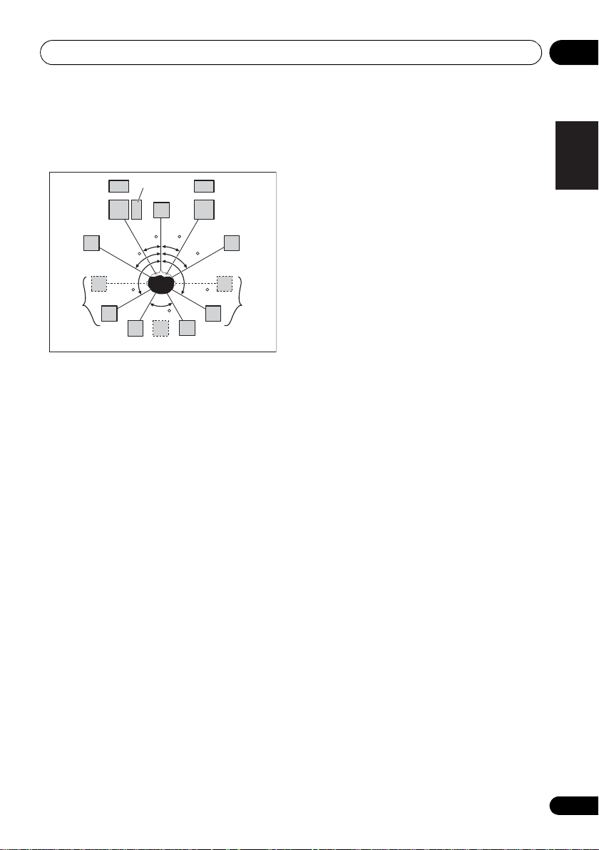
Placing the speakers
Refer to the chart below for placement of
speakers you intend to connect.
• Place the surround speakers at 120º from
the center. If you, (1) use the surround back
speaker, and, (2) don’t use the front height
speakers / front wide speakers, we
recommend placing the surround speaker
right beside you.
• If you intend to connect only one surround
back speakers, place it directly behind you.
• Place the left and right front height
speakers at least 1 m (3.3 ft.) directly above
the left and right front speakers.
Some tips for improving sound quality
Where you put your speakers in the room has a
big effect on the quality of the sound. The
following guidelines should help you to get the
best sound from your system.
• The subwoofer can be placed on the floor.
Ideally, the other speakers should be at
about ear-level when you’re listening to
them. Putting the speakers on the floor
(except the subwoofer), or mounting them
very high on a wall is not recommended.
• For the best stereo effect, place the front
speakers 2 m to 3 m (6 ft. to 9 ft.) apart, at
equal distance from the TV.
• If you’re going to place speakers around
your CRT TV, use shielded speakers or
place the speakers at a sufficient distance
from your CRT TV.
• If you’re using a center speaker, place the
front speakers at a wider angle. If not, place
them at a narrower angle.
• Place the center speaker above or below
the TV so that the sound of the center
channel is localized at the TV screen. Also,
make sure the center speaker does not
cross the line formed by the leading edge
of the front left and right speakers.
• It is best to angle the speakers towards the
listening position. The angle depends on
the size of the room. Use less of an angle
for bigger rooms.
• Surround and surround back speakers
should be positioned 60 cm to 90 cm (2 ft.
to 3 ft.) higher than your ears and tilted
slight downward. Make sure the speakers
don’t face each other. For DVD-Audio, the
speakers should be more directly behind
the listener than for home theater playback.
• Try not to place the surround speakers
farther away from the listening position
than the front and center speakers. Doing
so can weaken the surround sound effect.
English
Deutsch
Français
Italiano
Nederlands
Español
17
En

Connecting your equipment03
Connecting the speakers
Each speaker connection on the receiver
comprises a positive (+) and negative (–)
terminal. Make sure to match these up with the
terminals on the speakers themselves.
CAUTION
• These speaker terminals carry
HAZARDOUS LIVE voltage. To prevent
the risk of electric shock when connecting
or disconnecting the speaker cables,
disconnect the power cord before touching
any uninsulated parts.
• Make sure that all the bare speaker wire is
twisted together and inserted fully into the
speaker terminal. If any of the bare speaker
wire touches the back panel it may cause
the power to cut off as a safety measure.
Bare wire connections
A-Speaker terminals:
1 Twist exposed wire strands together.
2 Loosen terminal and insert exposed wire.
3 Tighten terminal.
Banana plug connections
(A-Speaker terminals only)
If you want to use speaker cables terminated
with banana plugs, screw the speaker terminal
fully shut, then plug the banana plug into the
end of the speaker terminal.
Important
• Please refer to the manual that came with
your speakers for details on how to connect
the other end of the speaker cables to your
speakers.
• Use an RCA cable to connect the subwoofer.
It is not possible to connect using speaker
cables.
CAUTION
• Make sure that all speakers are securely
installed. This not only improves sound
quality, but also reduces the risk of
damage or injury resulting from speakers
being knocked over or falling in the event of
external shocks such as earthquakes.
B-Speaker terminals:
1 Twist exposed wire strands together.
2 Push open the tabs and insert exposed
wire.
3 Release the tabs.
12 3
18
En

Connecting your equipment 03
HDMI
ASSIGNABLE
PB
PR
ASSIGNABLE
ASSIGNABLE
ASSIGNABLE
(
DVD
)
(
DVR/BDR
)
(
DVD
)
Y
P
B
PR
Y
P
B
PR
Y
L
R
R
FRONT CENTER SURROUND
SURROUND BACK
FRONT HEIGHT/WIDE/
LR LR L
RL
ZONE 2
OUT
DVR/BDR
DVD
OUT IN
CD—R/TAPE
OUT ININ
CD
IN
TV/SATINVIDEO
IN
(
DVR/BDR
)
(
OUTPUT 5 V 100 mA MAX
)
(CD)
(
Single
)
SUBWOOFER
(
TV/SAT
)
AM LOOP
FM UNBAL 75
COMPONENT VIDEO
AUDIO
PRE OUT
ANTENNA
OPTICAL
SIRIUS
ADAPTER PORT
VIDEO
IR CONTROL
SPEAKERS
SPEAKERS
MONITOR
OUT
LAN
COAXIAL
BD IN IN IN IN IN
OUT
(
10/100
)
IN
IN
1IN2
1
IN
1
IN
2
1 4
2 3 4
IN
1
A
IN
2
B
IN
OUTINOUT
LINE LEVEL
INPUT
Front left
Subwoofer
Center
Surround right
Surround back left
Surround back right
Front right
Surround left
7.1 ch surround setting
No connect
Surround back
6.1 ch surround setting
No connect
5.1 ch surround setting
No connect
Speaker B — left
Speaker B — right
Speaker B setting
Front wide left
Front wide right
Front height left
Front height setting
Front height right
The front height terminals can also be
used for the front wide and Speaker B.
Front wide setting
ZONE 2 setting
ZONE 2 — left
ZONE 2 — right
The surround back terminals
can also be used for Zone 2.
Installing your speaker system
At the very least, front left and right speakers only are necessary. Note that your main surround
speakers should always be connected as a pair, but you can connect just one surround back
speaker if you like (it must be connected to the left surround back terminal).
English
Deutsch
Français
Italiano
Nederlands
Español
19
En

Connecting your equipment03
HDMI
ASSIGNABLE
PB
PR
ASSIGNABLE
ASSIGNABLE
ASSIGNABLE
(
DVD
)
(
DVR/BDR
)
(
DVD
)
Y
P
B
PR
Y
P
B
PR
Y
L
R
R
FRONT CENTER SURROUND
SURROUND BACK
FRONT HEIGHT/WIDE/
LR LR L
RL
ZONE 2
OUT
DVR/BDR
DVD
OUT IN
CD—R/TAPE
OUT ININ
CD
IN
TV/SATINVIDEO
IN
(
DVR/BDR
)
(
OUTPUT 5 V 100 mA MAX
)
(CD)
(
Single
)
SUBWOOFER
(
TV/SAT
)
AM LOOP
FM UNBAL 75
COMPONENT VIDEO
AUDIO
PRE OUT
ANTENNA
OPTICAL
SIRIUS
ADAPTER PORT
VIDEO
IR CONTROL
SPEAKERS
SPEAKERS
MONITOR
OUT
LAN
COAXIAL
BD IN IN IN IN IN
OUT
(
10/100
)
IN
IN
1IN2
1
IN
1
IN
2
1 4
2 3 4
IN
1
A
IN
2
B
IN
OUTINOUT
High
Low
High
Low
Front left
Subwoofer
Center
Surround right
Front right
Surround left
Bi-amp compatible
speaker
Bi-amp compatible
speaker
Bi-amping your speakers
Bi-amping is when you connect the high
frequency driver and low frequency driver of
your speakers to different amplifiers for better
crossover performance. Your speakers must be
bi-ampable to do this (having separate
terminals for high and low) and the sound
improvement will depend on the kind of
speakers you’re using.
CAUTION
• Most speakers with both High and Low
terminals have two metal plates that
connect the High to the Low terminals.
These must be removed when you are biamping the speakers or you could severely
damage the amplifier. See your speaker
manual for more information.
20
En
• If your speakers have a removable
crossover network, make sure you do not
remove it for bi-amping. Doing so may
damage your speakers.
Bi-wiring your speakers
Your speakers can also be bi-wired if they
support bi-amping.
• With these connections, the Speaker
System setting makes no difference.
• To bi-wire a speaker, connect two speaker
cords to the speaker terminal on the receiver.
Using a banana plug for the second
connection is recommended.
• Don’t connect different speakers from the
• When bi-wiring as well, heed the cautions
CAUTION
same terminal in this way.
for bi-amping shown at the left.

Connecting your equipment 03
Selecting the Speaker system
The front height terminals can be used for front
wide and Speaker B connections, in addition to
for the front height speakers. Also, the
surround back terminals can be used for biamping and ZONE 2 connections, in addition
to for the surround back speakers. Make this
setting according to the application.
Front height setup
*Default setting
1 Connect a pair of speakers to the front
height speaker terminals.
See Connecting the speakers on page 18.
2 If necessary, select ‘
the
Speaker System
See Speaker system setting on page 100 to do
this.
Front wide setup
1 Connect a pair of speakers to the front
height speaker terminals.
See Connecting the speakers on page 18.
2 Select ‘
Speaker System
See Speaker system setting on page 100 to do
this.
Normal(SB/FW)
Speaker B setup
You can listen to stereo playback in another
room.
1 Connect a pair of speakers to the front
height speaker terminals.
See Connecting the speakers on page 18.
2 Select ‘
System
See Speaker system setting on page 100 to do
this.
Speaker B
menu.
menu.
menu.
’ from the
Normal(SB/FH)
’ from the
Speaker
’ from
Bi-Amping setup
Bi-amping connection of the front speakers for
high sound quality with 5.1-channel surround
sound.
1 Connect a Bi-amp compatible speakers to
the front and surround back speaker
terminals.
See Bi-amping your speakers on page 20.
2 Select ‘
System
See Speaker system setting on page 100 to do
this.
Front Bi-Amp
menu.
’ from the
Speaker
ZONE 2 setup
With these connections you can
simultaneously enjoy 5.1-channel surround
sound in the main zone with stereo playback
on another component in ZONE 2.
1 Connect a pair of speakers to the
surround back speaker terminals.
See Connecting the speakers on page 18.
2 Select ‘
menu.
See Speaker system setting on page 100 to do
this.
ZONE 2
’ from the
Speaker System
English
Deutsch
Français
Italiano
Nederlands
Español
21
En
Connecting your equipment03
High picture quality
Terminal for
connection with
source device
Terminal for
connection with TV
monitor
Video signals can be output
This product incorporates copyright protection
technology that is protected by method claims of certain
U.S. patents and other intellectual property rights owned
by Macrovision Corporation and other rights owners.
Use of this copyright protection technology must be
authorized by Macrovision Corporation, and is intended
for home and other limited viewing uses only unless
otherwise authorized by Macrovision Corporation.
Reverse engineering or disassembly is prohibited.
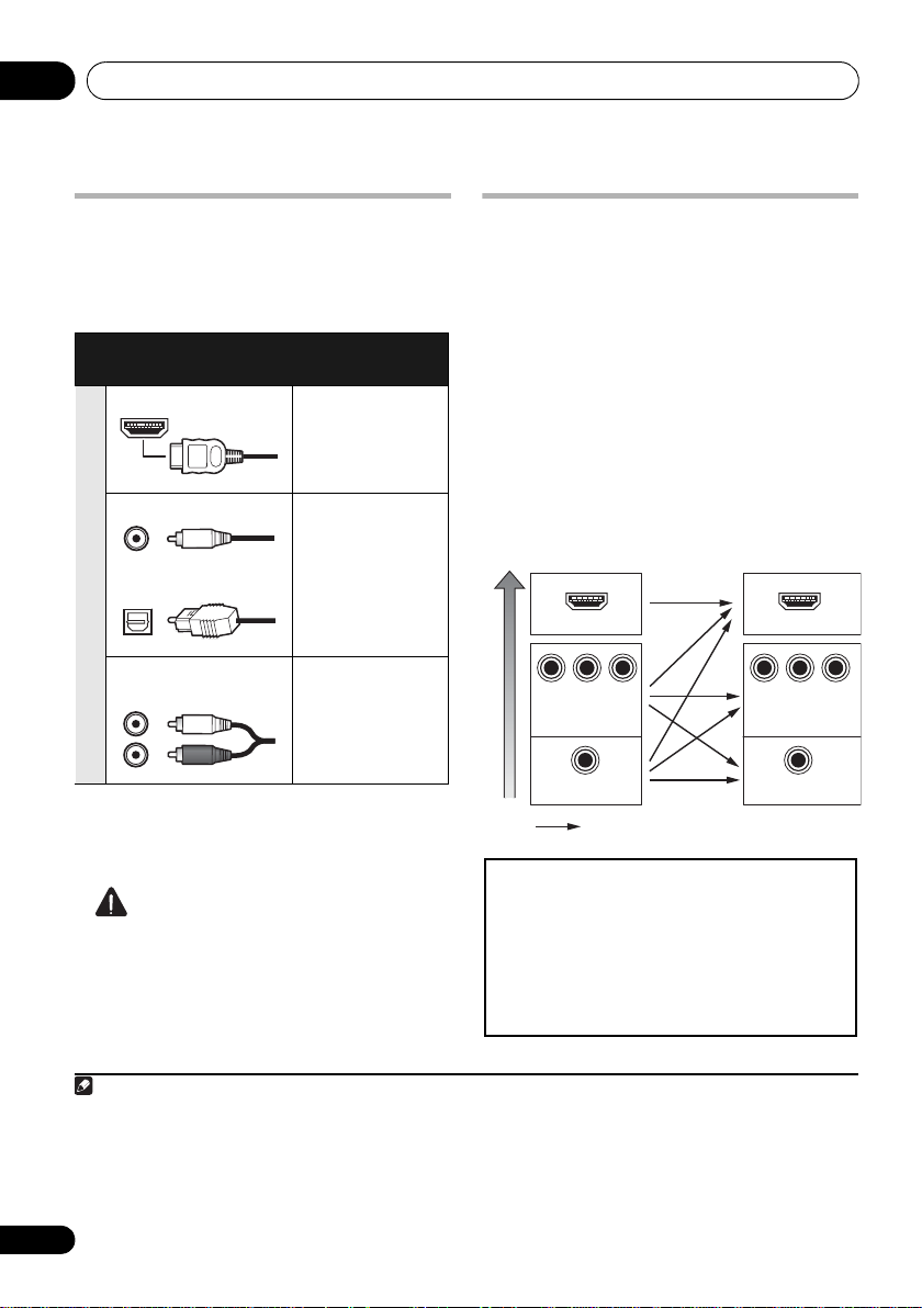
About the
audio connection
There are several types of audio input and output
terminals on this receiver. The receiver selects
the first available signal in the following order
when you choose
Types of cables and
AUTO
terminals
as the input signal:
Transferable
audio signals
HDMI HD audio
Digital (Coaxial) Conventional
digital audio
Sound signal priority
Digital (Optical)
RCA (Analog)
(White/Red)
Conventional
analog audio
• With an HDMI cable, video and audio
signals can be transferred in high quality
over a single cable.
About the video converter
The video converter ensures that all video
sources are output through all of the
MONITOR OUT jacks. The only exception is
HDMI: since this resolution cannot be
downsampled, you must connect your
monitor/TV to the receiver’s HDMI video
outputs when connecting this video source.
If several video components are assigned to
the same input function (see The Input Setup
menu on page 40), the converter gives priority
to HDMI, component, then composite (in that
order).
HDMI IN
P
P
B
VIDEO IN
VIDEO IN
R
Y
COMPONENT VIDEO
MONITOR OUT
MONITOR OUT
Y
COMPONENT
HDMI OUT
P
B
VIDEO
1
P
R
CAUTION
• When connecting optical cables, be careful
when inserting the plug not to damage the
shutter protecting the optical socket.
• When storing optical cable, coil loosely.
The cable may be damaged if bent around
sharp corners.
1 • If the video signal does not appear on your TV, try adjusting the resolution settings on your component or display.
Note that some components (such as video game units) have resolutions that may not be converted. In this case, try
switching Digital Video Conversion (in Setting the Video options on page 70) OFF.
• The signal input resolutions that can be converted from the component video input for the HDMI output are 480i/
576i, 480p/576p, 720p and 1080i. 1080p signal cannot be converted.
• Only signals with an input resolution of 480i/576i can be converted from the component video input for the
composite MONITOR OUT.
22
En

Connecting your equipment 03
HDMI IN
HDMI OUT HDMI OUT
DIGITAL OUT
OPTICAL
ANALOG
RL
AUDIO OUT
Other HDMI/DVIequipped component
HDMI/DVI-compatible
Blu-ray disc player
HDMI/DVI-compatible TV
Select one
This connection is
required in order to
listen to the sound of
the TV over the receiver.
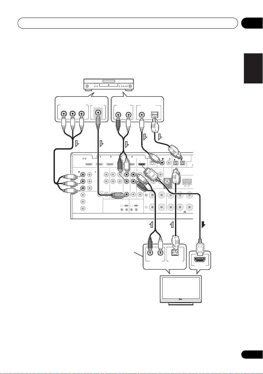
Connecting your TV and playback components
Connecting using HDMI
If you have an HDMI or DVI (with HDCP) equipped component (BD: Blu-ray disc player, etc.), you
can connect it to this receiver using a commercially available HDMI cable.
If the TV and playback components support the Control with HDMI feature, the convenient
Control with HDMI functions can be used (see Control with HDMI function on page 62).
1
BD IN IN IN IN IN
HDMI
ASSIGNABLE
1 4
COMPONENT VIDEO
ASSIGNABLE
1
2
IN
IN
(
)
(
MONITOR
OUT
DVR/BDR
VIDEO
)
Y
P
B
P
R
DVD
Y
P
B
P
R
Y
P
B
P
R
AUDIO
L
R
ZONE 2
OUT
2 3 4
DVR/BDR
DVD
OUT IN
IR CONTROL
IN
OUTINOUT
TV/SATINVIDEO
OUT
CD
IN
IN
ASSIGNABLE
LAN
COAXIAL
(
)
10/100
IN
1IN2
IN
(
)
(CD)
DVD
PRE OUT
SUBWOOFER
CD-R/TAPE
OUT ININ
FRONT CENTER SURROUND
LR
R
1
(
)
TV/SAT
ANTENNA
SPEAKERS
IN
2
(
DVR/BDR
OPTICAL
ASSIGNABLE
)
AM LOOP
A
(
OUTPU
English
Deutsch
Français
Italiano
Nederlands
Español
• For input components, connections other
than HDMI connections are also possible
(see Connecting your DVD player with no
HDMI output on page 25).
• If you want to listen to the sound of the TV
over the receiver, connect the receiver and
TV with audio cables.
23
En

Connecting your equipment03
About HDMI
1
The HDMI connection transfers
uncompressed digital video, as well as almost
every kind of digital audio that the connected
component is compatible with, including DVDVideo, DVD-Audio, SACD, Dolby Digital Plus,
Dolby TrueHD, DTS-HD Master Audio (see
below for limitations), Video CD/Super VCD
and CD. See About the video converter on
page 22 for more on HDMI compatibility.
This receiver incorporates High-Definition
Multimedia Interface (HDMI
This receiver supports the functions described
below through HDMI connections.
®
) technology.
2
• Digital transfer of uncompressed video
(contents protected by HDCP (1080p/24,
1080p/60, etc.))
• 3D signal transfer
• Deep Color signal transfer
• x.v.Color signal transfer
3
3
3
• Input of multi-channel linear PCM digital
audio signals (192 kHz or less) for up to 8
channels
• Input of the following digital audio
formats:
4
– Dolby Digital, Dolby Digital Plus, DTS,
High bitrate audio (Dolby TrueHD, DTS-HD
Master Audio, DTS-HD High Resolution
Audio), DVD-Audio, CD, SACD (DSD
signal), Video CD, Super VCD
• Synchronized operation with components
using the Control with HDMI function (see
Control with HDMI function on page 62)
HDMI, the HDMI Logo and High-Definition
Multimedia Interface are trademarks or
regi ste re d trad em ark s of HDM I L ice nsi ng, LLC in
the United States and other countries.
“x.v.Color” and x.v.Color logo are trademarks of
Sony Corporation.
1 • An HDMI connection can only be made with DVI-equipped components compatible with both DVI and High
Bandwidth Digital Content Protection (HDCP). If you choose to connect to a DVI connector, you will need a separate
adaptor (DVIHDMI) to do so. A DVI connection, however, does not support audio signals. Consult your local audio
dealer for more information.
• If you connect a component that is not compatible with HDCP, an HDCP ERROR message is displayed on the front
panel display. Some components that are compatible with HDCP still cause this message to be displayed, but so long
as there is no problem with displaying video this is not a malfunction.
• Depending on the component you have connected, using a DVI connection may result in unreliable signal transfers.
This receiver supports SACD,
•
these formats, however, make sure that the component connected to this receiver also supports the corresponding
format.
2 • Use a High Speed HDMI® cable. If HDMI cable other than a High Speed HDMI® cable is used, it may not work
properly.
• When an HDMI cable with a built-in equalizer is connected, it may not operate properly.
3 Signal transfer is only possible when connected to a compatible component.
4 • HDMI format digital audio transmissions require a longer time to be recognized. Due to this, interruption in the
audio may occur when switching between audio formats or beginning playback.
• Turning on/off the device connected to this unit’s HDMI OUT terminal during playback, or disconnecting/
connecting the HDMI cable during playback, may cause noise or interrupted audio.
Dolby Digital Plus, Dolby TrueHD
and
DTS-HD Master Audio
. To take advantage of
24
En
Connecting your equipment 03
HDMI IN
DIGITAL OUT
COAXIAL OPTICAL
ANALOG
RL
AUDIO OUT
VIDEO OUT
Y
P
B
PR
COMPONENT VIDEO OUT
DIGITAL OUT
OPTICAL
ANALOG
RL
AUDIO OUT
DVD player etc.
HDMI/DVI-compatible TV
Select one
Select one
Select one
This connection is
required in order to
listen to the sound of
the TV over the receiver.
Connecting your DVD player with no HDMI output
This diagram shows connections of a TV (with HDMI input) and DVD player (or other playback
component with no HDMI output) to the receiver.
1
IN
(
DVR/BDR
P
P
VIDEO
Y
2
B
R
AUDIO
)
L
R
2 3 4
ZONE 2
DVR/BDR
OUT IN
OUT
DVD
TV/SATINVIDEO
IR CONTROL
IN
OUTINOUT
OUT
CD
IN
IN
BD IN IN IN IN IN
HDMI
ASSIGNABLE
1 4
COMPONENT VIDEO
ASSIGNABLE
1
IN
(
)
DVD
Y
P
B
P
R
Y
B
P
P
R
MONITOR
OUT
ASSIGNABLE
LAN
COAXIAL
(
)
10/100
IN
1IN2
(
)
(CD)
DVD
PRE OUT
SUBWOOFER
CD-R/TAPE
OUT ININ
FRONT CENTER SURROUND
LR
R
IN
1
(
TV/SAT
ANTENNA
SPEAKERS
OPTICAL
ASSIGNABLE
IN
2
A
(
OUTPUT
(
)
)
DVR/BDR
AM LOOP
F
A
English
Deutsch
Français
Italiano
Nederlands
Español
• If you want to listen to the sound of the TV over the receiver, connect the receiver and TV with
audio cables.
25
En

Connecting your equipment03
DVD player etc.
TV
Select one
Select one
Select one
Select one
This connection is
required in order to
listen to the sound of
the TV over the receiver.
Connecting your TV with no HDMI input
This diagram shows connections of a TV (with no HDMI input) and DVD player (or other playback
component) to the receiver.
• With these connections, the picture is not output to the TV even if the DVD player is connected with
an HDMI cable. Connect the DVD player’s video signals using a composite or component cord.
COMPONENT VIDEO OUT
PR
B
P
Y
VIDEO OUT
HDMI
ASSIGNABLE
COMPONENT VIDEO
1
IN
(
DVD
Y
PB
PR
Y
P
B
PR
HDMI OUT
1
BD IN IN IN IN IN
1 4
ASSIGNABLE
2
IN
)
(
)
DVR/BDR
Y
P
B
PR
MONITOR
OUT
VIDEO
PR
COMPONENT VIDEO IN
AUDIO
L
R
ZONE 2
P
OUT
B
AUDIO OUT
ANALOG
RL
2 3 4
DVR/BDR
DVD
OUT IN
IR CONTROL
IN
OUTINOUT
Y
VIDEO IN
COAXIAL OPTICAL
TV/SATINVIDEO
IN
DIGITAL OUT
OUT
LAN
(
)
10/100
CD
CD-R/TAPE
OUT ININ
IN
FRONT CENTER SURROUND
R
RL
ANALOG
AUDIO OUT
ASSIGNABLE
COAXIAL
IN
1IN2
(
)
(CD)
DVD
PRE OUT
SUBWOOFER
LR
IN
1
(
TV/SAT
ANTENNA
SPEAKERS
OPTICAL
DIGITAL OUT
OPTICAL
ASSIGNABLE
IN
2
(
OUTP
(
)
)
DVR/BDR
AM LOOP
A
• Connect using an HDMI cable to listen to HD audio on the receiver. Do not use an HDMI cable
to input video signals.
Depending on the video component, it may not be possible to output signals connected by
HDMI and other methods simultaneously, and it may be necessary to make output settings.
Please refer to the operating instructions supplied with your component for more information.
26
En

Connecting your equipment 03
ANALOG
RL
AUDIO IN
VIDEO IN
ANALOG
RL
AUDIO OUT
VIDEO OUT
DIGITAL OUT
COAXIAL OPTICAL
HDD/DVD recorder, VCR, etc.
Select one
Connecting a satellite/cable
receiver or other set-top box
Satellite and cable receivers, and terrestrial
digital TV tuners are all examples of so-called
‘set-top boxes’.
When you set up the receiver you’ll need to tell
the receiver which input you connected the settop box to (see The Input Setup menu on
page 40).
2 3 4
IN IN
DVR/BDR
DVD
OUT IN
IR CONTROL
IN
OUTINOUT
TV/SATINVIDEO
VIDEO OUT
OUT
CD
IN
ASSIGNABLE
COAXIAL
LAN
(
)
10/100
IN
1IN2
(
)
(CD)
DVD
PRE OUT
SUBWOOFER
CD-R/TAPE
OUT ININ
IN
FRONT CENTER SURROUND
R
LR LR
RL
ANALOG
AUDIO OUT
OPTICAL
ASSIGNABLE
IN
IN
1
2
(
OUTPUT 5 V 100 mA MA
(
)
(
)
DVR/BDR
TV/SAT
ANTENNA
AM LOOP
A
SPEAKERS
COAXIAL OPTICAL
DIGITAL OUT
ADAPTER PO
FM UNBAL 75
SURRO
Connecting a HDD/DVD recorder,
English
VCR and other video sources
This receiver has two sets of audio/video inputs
and outputs suitable for connecting analog or
digital video devices, including HDD/DVD
recorders and VCRs.
When you set up the receiver you’ll need to tell
the receiver which input you connected the
recorder to (see also The Input Setup menu on
page 40).
122 3 4
IN IN IN IN
AUDIO
)
R/BDR
L
R
B
ZONE 2
DVR/BDR
OUT IN
OUT
R
EO
DVD
TV/SATINVIDEO
IR CONTROL
IN
OUTINOUT
OUT
IN
ASSIGNABLE
LAN
COAXIAL
(
)
10/100
IN
1IN2
(
)
(CD)
DVD
PRE OUT
SUBWOOFER
CD
CD-R/TAPE
OUT ININ
IN
FRONT CENTER SURROUND
LR
R
IN
1
(
TV/SAT
ANTENNA
SPEAKERS
IN
(
)
DVR/BDR
OPTICAL
2
AM LOOP
ASSIGNABL
)
A
(
OUT
Deutsch
Français
Italiano
Nederlands
Español
• In order to record, you must connect the
analog audio cables (the digital connection
is for playback only).
27
En

Connecting your equipment03
ANALOG
RL
AUDIO OUT
DIGITAL OUT
COAXIAL OPTICAL
RL
AUDIO IN
REC
CD-R, MD, DAT, etc.
Select one
Connecting other audio
components
This receiver has both digital and analog
inputs, allowing you to connect audio
components for playback.
One of these inputs have corresponding outputs
for use with analog audio recorders.
When you set up the receiver you’ll need to tell
the receiver which input you connected the
component to (see also The Input Setup menu
on page 40).
4
IN
TV/SATINVIDEO
CONTROL
IN
OUT
OUT
CD
IN
ASSIGNABLE
LAN
COAXIAL
(
)
10/100
IN
1IN2
(
)
(CD)
DVD
PRE OUT
SUBWOOFER
CD-R/TAPE
OUT IN
IN
FRONT CENTER SURROUND
R
LR LR
IN
1
(
TV/SAT
ANTENNA
SPEAKERS
OPTICAL
IN
2
(
)
DVR/BDR
AM LOOP
ASSIGNABLE
ADAPTER PORT
(
OUTPUT 5 V 100 mA MAX
)
FM UNBAL 75
A
)
SURROUN
• If your turntable has line-level outputs (i.e.,
it has a built-in phono pre-amp), connect it
to the CD inputs instead.
• If you’re connecting a recorder, connect
the analog audio outputs to the analog
audio inputs on the recorder.
About the WMA9 Pro decoder
This unit has an on-board Windows Media™
Audio 9 Professional
it is possible to playback WMA9 Pro-encoded
audio using HDMI, coaxial or optical digital
connection when connected to a WMA9 Procompatible player. However, the connected
DVD player, set-top box, etc. must be able to
output WMA9 Pro format audio signals
through a coaxial or optical digital output.
1
(WMA9 Pro) decoder, so
1• Windows Media and the Windows logo are trademarks or registered trademarks of Microsoft Corporation in the United
States and/or other countries.
28
• With WMA9 Pro, sound problems may occur depending on your computer system. Note that WMA9 Pro 96 kHz
sources will be downsampled to 48 kHz.
En

Connecting your equipment 03
AM LOOP
FM UNBAL 75
ANTENNA
Outdoor
antenna
5 m to 6 m
(16 ft. to 20 ft.)
Indoor antenna
(vinyl-coated wire)
Connecting AM/FM antennas
Connect the AM loop antenna and the FM wire
antenna as shown below. To improve reception
and sound quality, connect external antennas
(see Connecting external antennas below).
fig. a fig. b fig. c
3
1
4
5
ANTENNA
AM LOOP
FM UNBAL 75
1 Pull off the protective shields of both AM
antenna wires.
2 Push open the tabs, then insert one wire
fully into each terminal, then release the tabs
to secure the AM antenna wires.
3 Fix the AM loop antenna to the attached
stand.
To fix the stand to the antenna, bend in the
direction indicated by the arrow (fig. a) then
clip the loop onto the stand (fig. b).
• If you plan to mount the AM antenna to a
wall or other surface, secure the stand with
screws (fig. c) before clipping the loop to
the stand. Make sure the reception is clear.
2
4 Place the AM antenna on a flat surface
and in a direction giving the best reception.
5 Connect the FM wire antenna into the FM
antenna socket.
For best results, extend the FM antenna fully
and fix to a wall or door frame. Don’t drape
loosely or leave coiled up.
Connecting external antennas
To improve FM reception connect an external
FM antenna to the FM UNBAL 75 Ω.
To improve AM reception, connect a 5 m to 6 m
(16 ft. to 20 ft.) length of vinyl-coated wire to the
AM LOOP terminals without disconnecting
the supplied AM loop antenna.
For the best possible reception, suspend
horizontally outdoors.
ANTENNA
AM LOOP
FM UNBAL 75
English
Deutsch
Français
Italiano
Nederlands
Español
29
En

Connecting your equipment03
HDMI
ASSIGNABLE
PB
PR
ASSIGNABLE
(
DVD
)
Y
P
B
PR
Y
P
B
PR
Y
L
R
ZONE 2
OUT
(
DVR
)
COMPONENT VIDEO
AUDIO
VIDEO
MONITOR
OUT
BD IN IN IN
1
IN
1
IN
2
1 4
D
SURROUND BACK
L RL
)
(
Single
)
FM UNBAL 75
SIRIU
ADAPTER PORT
IN
HDMI
ASSIGNABLE
PB
PR
ASSIGNABLE
(
DVD
)
Y
P
B
PR
Y
P
B
PR
Y
L
R
ZONE 2
OUT
DVR
OUT
(
DVR/BDR
)
COMPONENT VIDEO
AUDIO
VIDEO
MONITOR
OUT
BD IN IN IN
1
IN
1
IN
2
1 4
2
MULTI-ZONE setup
This receiver can power up to two independent
systems in separate rooms after you have
made the proper MULTI-ZONE connections.
Different sources can be playing in two zones
at the same time or, depending on your needs,
the same source can also be used. The main
and sub zone have independent power (the
main zone power can be off while sub zone is
on) and the sub zone can be controlled by the
remote or front panel controls.
Making MULTI-ZONE connections
It is possible to make these connections if you
have a separate TV and speakers for the sub
zone (ZONE 2). You will also need a separate
amplifier if you are not using the MULTI-ZONE
setup using speaker terminals (ZONE 2) below
for the sub zone.
MULTI-ZONE listening options
The following table shows the signals that can
be output to ZONE 2:
Sub Zone Input functions available
ZONE 2 DVD, TV/SAT, DVR/BDR, VIDEO,
INTERNET RADIO, iPod/USB, CD, CDR/TAPE, TUNER, ADAPTER PORT,
SIRIUS
(Outputs analog audio and composite
video.)
MULTI-ZONE setup using speaker
terminals (ZONE 2)
You must select ZONE 2 in Speaker system
setting on page 100 to use this setup.
• Connect a TV monitor to the
2 OUT
jacks on this receiver.
VIDEO ZONE
You should have a pair of speakers attached to
the surround back speaker terminals as shown
below.
30
En
Basic MULTI-ZONE setup (ZONE 2)
• Connect a separate amplifier to the
ZONE 2 OUT
VIDEO ZONE 2 OUT
You should have a pair of speakers attached to
the sub zone amplifier as shown in the
jacks and a TV monitor to the
jack, both on this receiver.
AUDIO
following illustration.
Loading…
Перейти к контенту
Ресиверы и усилители Pioneer
- Размер инструкции: 8.38 Мб
- Формат файла: pdf
Если вы потеряли инструкцию от ресивера и усилителя Pioneer VSX-920 / VSX-1020 / VSX-1025, можете скачать файл для просмотра на компьютере или печати.
Инструкция для ресивера и усилителя Pioneer VSX-920 / VSX-1020 / VSX-1025 на русском языке. В руководстве описаны возможности и полезные функции, а также правила эксплуатации. Перед использованием внимательно ознакомьтесь с инструкцией.
Чтобы не читать всю инструкцию вы можете выполнить поиск по содержимому внутри инструкции и быстро найти необходимую информацию. Рекомендации по использованию помогут увеличить срок службы ресивера и усилителя Pioneer VSX-920 / VSX-1020 / VSX-1025. Если у вас появилась проблема, то найдите раздел с описанием неисправностей и способами их решения. В нем указаны типичные поломки и способы их решения.
Инструкция и руководство для
Pioneer VSX-1020-K
20 страниц подробных инструкций и пользовательских руководств по эксплуатации на русском

2
Об этом руководстве
Данные инструкции по эксплуатации предназначены для приложения, отображающего на экране компьютера
реверберационные частотные характеристики комнаты для прослушивания, характеристики групповой
задержки громкоговорителей и параметры МСАСС, измеренные функцией Advanced MCACC (Расширенная
настройка МСАСС) ресивера.
В нем объясняются все вопросы, необходимые для использования данного приложения, от установки до
устранения неполадок. Для использования данного приложения понадобится управление ресивером, поэтому
используйте также инструкции по эксплуатации, прилагаемые к данному ресиверу.
Важная информация
Описания по функциям «Group Delay» (Групповая задержка) («характеристики групповой
задержки громкоговорителей», др.), содержащиеся в данных инструкциях по эксплуатации,
относятся только для ресиверов, поддерживающих функцию Full Band Phase Control
(
Полнодиапазонное управление фазой).
О приложении «Advanced MCACC» (Расширенная
настройка MCACC)
Функции приложения Advanced MCACC (Расширенная настройка МСАСС) используются с той-же целью, как и
функции «Reverb View» (Обзор ревербераций) и «Group Delay» (Групповая задержка) самого ресивера (см.
инструкции по эксплуатации к ресиверу), то есть для отображения реверберационных характеристик среды
прослушивания и характеристик групповой задержки громкоговорителей. Используя компьютер, можно
получить более чистые, легко читаемые графики. Приложение также используется для отображения
измеренных значений, хранящихся в памяти МСАСС ресивера.
Требования для использования приложения на компьютере
• В компьютере должна быть установлена одна из следующих операционных систем: Microsoft
®
Windows
®
Vista Home Basic/Home Premium/Ultimate SP1 или Windows
®
XP Professional/Home Edition
SP3.
• Монитор должен обладать разрешением экрана 800 x 600 точек (SVGA) или больше.
• Компьютер должен быть оборудован портом USB (для передачи данных измерений с ресивера на
компьютер требуется отдельное устройство USB).
Microsoft
®
, Windows
®
Vista и Windows
®
XP являются зарегистрированными торговыми марками или торговыми
марками Microsoft Corporation в США и/или других странах.
Основные функции приложения
1. Отображает трехмерные графики реверберационных частотных характеристик используемой комнаты.
Эти измерения можно просматривать на выбор как без корректировки, выполняемой данным ресивером
(до и после калибровки), так и с ней.
2. Позволяет отобразить трехмерные графики характеристик групповой задержки различных
громкоговорителей. (Можно отобразить значения до и после калибровки.)
3. Позволяет отобразить список параметров Advanced MCACC (Расширенная настройка MCACC)
(результаты измерений).
4. Позволяет осуществлять просмотр графиков в различных форматах.
5. Позволяет сохранить различные измеренные данные на компьютере.
6. Позволяет делать заметки об условиях в комнате, в которой производились измерения, др.
7. Позволяет распечатывать различные графики и измеренные значения МСАСС.

3
О приложении Advanced MCACC (Расширенная настройка MCACC) (Продолжение)
Задачи, выполняемые с помощью этого приложения
1. Advanced EQ Setup (Расширенная настройка эквалайзера), которую можно выполнить с помощью
ресивера (см. инструкции по эксплуатации к ресиверу), позволяет выбрать оптимальный период
времени для автоматической настройки эквалайзера. Реверберационные характеристики (Reverb)
данного приложения можно использовать в качестве руководства в выборе наилучшего временного
периода для используемой комнаты.
Подробнее, см.
Определение временного периода для калибровки Advanced EQ Setup (Расширенная
настройка эквалайзера) (стр. 18)
.
2. Искажение реверберационных частотных характеристик в комнате для прослушивания может помешать
в получении точного звукового поля. Графики, отображаемые данным приложением, являются
эффективным инструментом, поскольку позволяют проверить эти реверберационные частотные
характеристики мгновенно. Также можно проверить эффективность действий, предпринятых для
улучшения звучания в комнате для прослушивания, например, установки звукопоглощающих
материалов.
Подробнее, см.
Действия по улучшению реверберационных характеристик комнаты (стр. 20)
.
3. Можно отобразить реверберационные характеристики после калибровки. Это позволит проверить
эффекты эквалайзера произведенных измерений Advanced MCACC.
Подробнее, см.
Об экране графиков реверберационных характеристик до и после калибровки (стр. 22)
.
4. Графики Group Delay (Групповая задержка) позволяют просмотреть характеристики групповой
задержки до и после калибровки.
Подробнее, см.
Чтение графика характеристик групповой задержки (Group Delay) (стр. 24)
.
5. Экран параметров MCACC (Parameters) позволяет отобразить на компьютере все параметры
(измеренные значения), сохраненные в памяти МСАСС ресивера.
Подробнее, см.
Отображение параметров МСАСС (стр. 25)
.

4
Установка приложения
Установите данное приложение на используемый компьютер с помощью загруженной программы установки.
Программа установки находится в папке, которая была указана при загрузке приложения.
Если на компьютере установлена предыдущая версия Advanced MCACC («Ver. 1.1», «Ver. 1.4», «Ver. 2.0», «Ver. 2.1»
или «Ver. 2.2»), пожалуйста, обновите приложение. Подробнее, см.
Обновление приложения (стр. 26)
.
1
Дважды щелкните на файл «PioneerAdvancedMCACC_e_ver_*_*.exe» .
Цифрой после «ver» в имени файла обозначается номер версии программы установки.
В зависимости от текущей конфигурации компьютера, до отображения InstallShield Wizard может уйти некоторое время.
2
Щелкните на кнопке «Next» (Далее).
3
(
Если вы согласны с содержанием License Agreement (Лицензионное
Соглашение)), выберите «I accept the terms in the license agreement» (Принимаю
условия лицензионного соглашения), затем выберите «Next» (Далее).
Появляется экран программы установки для выбора папки для установки.
Устранение неполадок
Если при двойном щелчке на
происходит ошибка, и не удается продолжить установку.
Continue
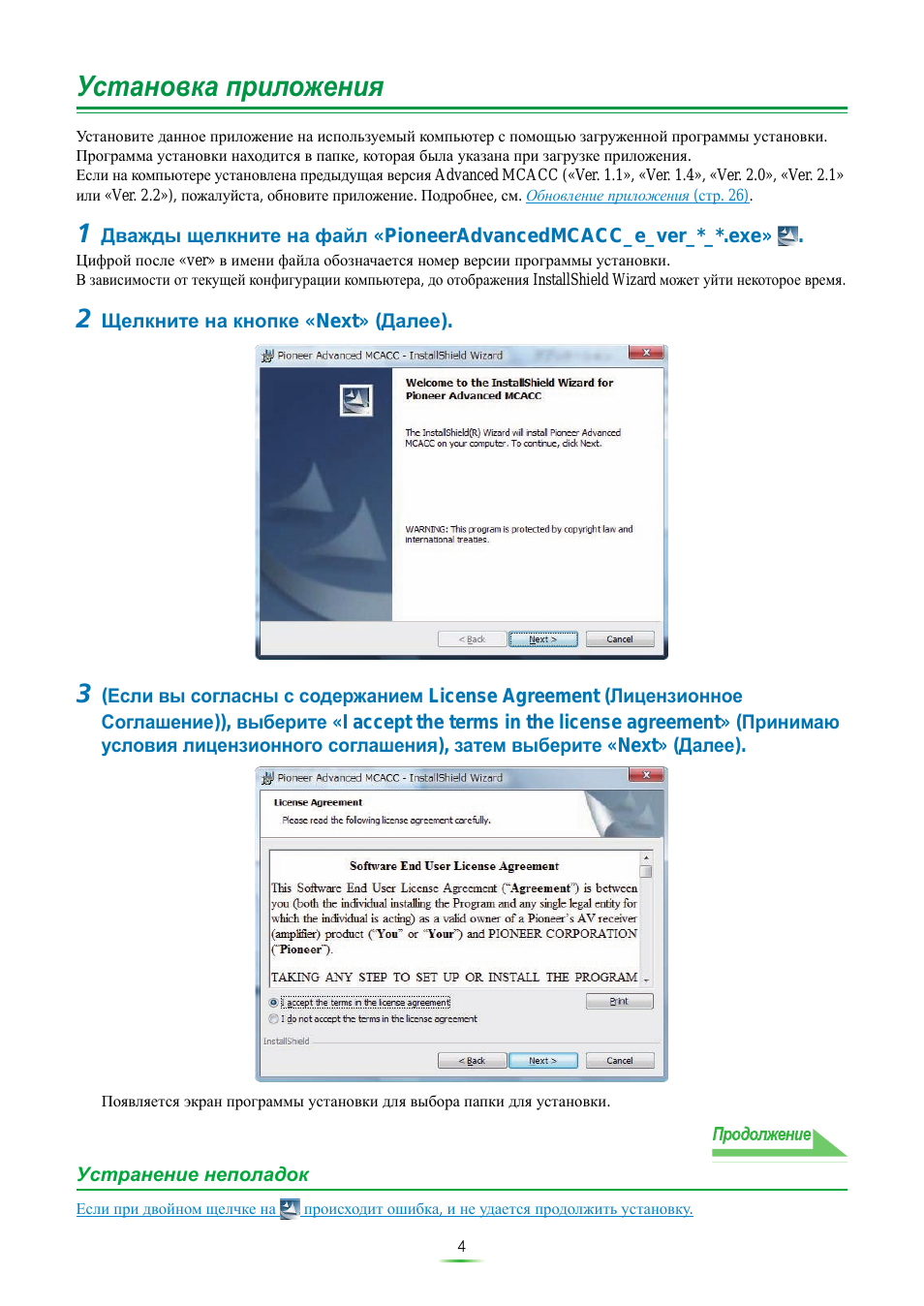
5
Установка приложения (Продолжение)
4
Введите Customer Information (Информация о клиенте), затем выберите
«Next» (
Далее).
5
Щелкните на кнопке «Next» (Далее).
Приложение устанавливается в папку, обозначенную в «Destination Folder» (Папка-получатель). Папку-
получатель можно изменить, щелкнув на «Change…» (Изменить).
Continue
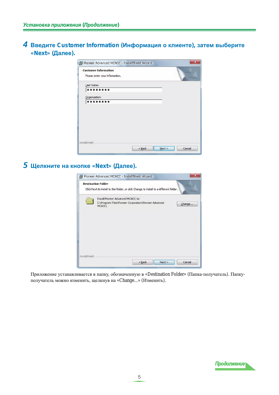
6
Установка приложения (Продолжение)
6
Выберите «Install» (Установить).
На рабочем столе создается ярлык
.
7
Щелкните на кнопке «Finish» (Завершить).
Установка завершена.
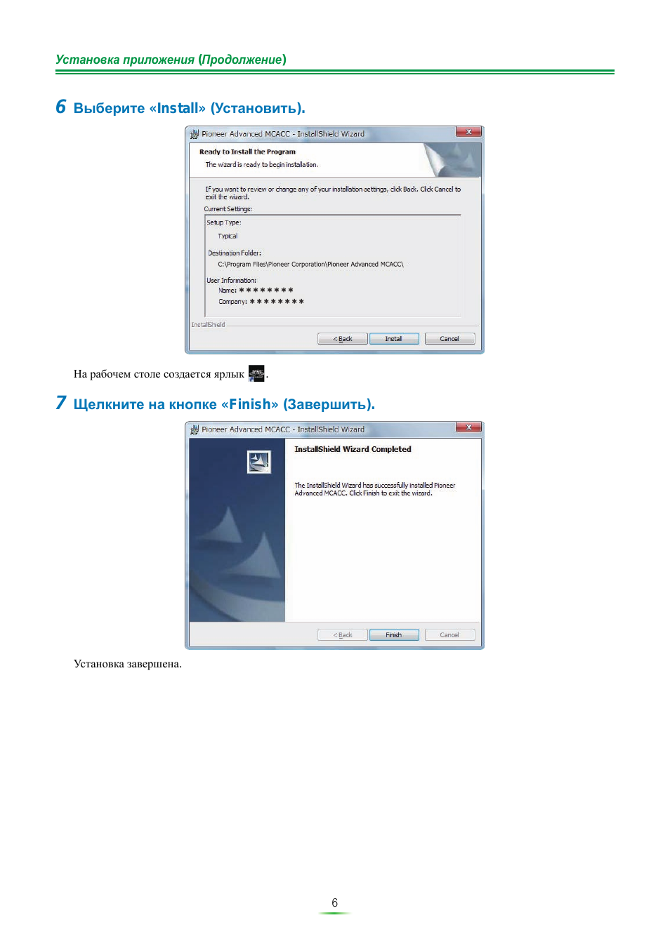
7
Управление ресивером и подключениями USB
Для отображения различных данных, измеренных на ресивере с экрана компьютера, выполните процедуру ниже
и подключите устройство USB для передачи данных ресивера.
1
Выполните операцию «Full Auto MCACC» (Полная автоматическая
настройка МСАСС) на ресивере. (См. инструкции по эксплуатации к
ресиверу.)
Указанные здесь измерения не требуются, если операция «Full Auto MCACC» (Полная автоматическая
настройка МСАСС) уже была произведена. Перейдите на
шаг 2
.
2
Выберите «Output MCACC data» (Вывод данных МСАСС) в «MCACC Data
Check» (
Проверка данных МСАСС). (См. инструкции по эксплуатации к
ресиверу.)
На экране монитора отображается сообщение «Please connect your USB memory for the MCACC data, then
press OK to output them.» (Пожалуйста, подключите устройство памяти USB для данных MCACC, затем
нажмите ОК для их вывода), и ресивер переключается в режим ожидания передачи. Он готов к отправке
данных на устройство USB. (Отображение на экране дисплея может различаться в зависимости от модели
ресивера.)
3
Подключите устройство USB к терминалу USB на передней панели, затем
выберите «OK».
(Иллюстрация ресивера может различаться в зависимости от модели ресивера.)
На экране будет отображаться «Please wait…» и запустится передача данных измерений на устройство USB.
Передача завершается по отображению «Complete» (Завершено).
На этом завершается подготовка к отправке данных измерений на устройство USB.
(Для отправки данных прейдите к следующему разделу Управление приложением.)
a. Speaker Setting
b. Channel Level
c. Speaker Distance
2.MCACC Data Check
d. Standing Wave
e. Acoustic Cal EQ
f. Group Delay
g. Output MCACC data
A/V RECEIVER
Exit
Return
Please connect your USB memory for the MCACC data,
then press OK to output them.
2g.Output MCACC data
Exit
Cancel
A/V RECEIVER
OK
MASTER
VOLUME
MCACC
SETUP MIC
VIDEO CAMERA
iPod
iPhone
USB
HDMI 5
Continue
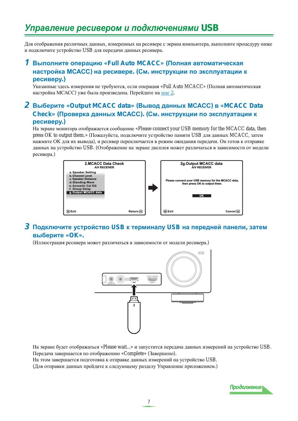
8
Управление ресивером и подключениями USB (Продолжение)
• Не отсоединяйте устройство USB или отключайте питание, пока не завершена передача данных.
• На экране можно отобразить графики до калибровки («Before») и после калибровки («After»), отображая
графики реверберационных характеристик после измерений Full Auto MCACC (Полная автоматическая
настройка МСАСС) («Reverb»), но помните, что график, отображаемый для характеристик после
калибровки является прогнозом реверберационных характеристик после измерений Full Auto MCACC
(Полная автоматическая настройка МСАСС) в режиме EQ Type (Тип эквалайзера): SYMMETRY
(Симметрия).
Подробнее, см.
Об экране графиков реверберационных характеристик до и после калибровки (стр. 22)
.
Для просмотра графика реально измеренных реверберационных характеристик после калибровки МСАСС
(не прогноза), снова измерьте реверберационные характеристики после калибровки.
Подробнее, см.
Отображение реверберационных характеристик после калибровки эквалайзера (реально
измеренные значения) (стр. 23)
.
• Если калибровка производится в режиме EQ Type (Тип эквалайзера) в Full Auto MCACC (Полная
автоматическая настройка МСАСС), установленным на любую настройку, кроме SYMMETRY
(Симметрия) (ALL CH ADJ (Регулировка всех каналов) или FRONT ALIGN (Выровнять фронт)),
невозможно будет предугадать реверберационные характеристики после калибровки, поэтому график
характеристик после калибровки («After») не может отображаться. В таком случае, график характеристик
после калибровки можно отобразить, повторно измерив реверберационные характеристики с тем-же EQ
Type (Тип эквалайзера), как и типом, использованным для калибровки. Подробнее, см.
Отображение
реверберационных характеристик после калибровки эквалайзера (реально измеренные значения) (стр. 23)
.
Примечание
9
Управление приложением
В этом разделе описываются процедуры, выполняемые в приложении, начиная от открытия данных измерений
до отображения графиков и сохранения данных.
Открытие данных измерений
1
Дважды щелкните на ярлыке
приложения на рабочем столе
компьютера.
Приложение также можно запустить, выбрав «Program» (Программа)
«Pioneer Corporation» (Корпорация
Pioneer)
«Advanced MCACC» в меню «Start» (Запуск).
Приложение запускается.
2
Подключите устройство USB, на которые были переданы данные
измерений, к порту USB компьютера.
3
Выберите «Open» (Открыть) в строке меню «File» (Файл).
4
Выберите нужный файл «.mcacc» на устройстве USB, затем щелкните
«Open» (
Открыть).
Отображаются данные измерений.
• Данные, используемые для отображения графика реверберационных характеристик (Reverb), Графика
характеристик групповой задержки (Group Delay) и параметров МСАСС, не удаляются даже при отключении
питания ресивера. Однако, относительно данных, используемых для отображения графика реверберационных
характеристик (Reverb) и данных характеристик групповой задержки, данные, хранящиеся на ресивере,
перезаписываются после повторного измерения ревербераций. Если нужно отобразить графики нескольких
наборов данных, выполняйте передачу данных на устройство USB при каждом выполнении измерений на
ресивере.
Примечание
Continue
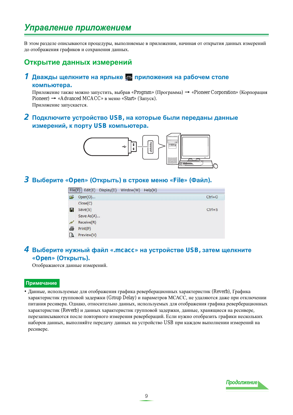
10
Управление приложением (Продолжение)
Экраны графиков и параметров (названия и функции элементов)
При приеме данных измерений, отображается окно экрана графиков и параметров. Окно дисплея разделено на
три параметра: «Reverb» (Реверберация), «Group Delay» (Групповая задержка) и «Parameters» (Параметры).
Выберите нужный ярлык для переключения на нужное окно и отображения соответствующих деталей.
Reverb (
Реверберация) (график реверберационных частотных характеристик
комнаты)
Можно переключать экран графиков реверберационных характеристик до и после калибровки. Можно
переключать отдельные экраны для различных каналов/частот или экран списка всех каналов/частот (ALL).
Ниже описаны различные части отдельных экранов и экрана ALL, с использованием в качестве примера экрана
каналов.
Отдельный экран (пример: Передний канал)
Экран «ALL» (ВСЕ)
1
2
3
4
5
6
7
8
9
10
11
12
13
14
15
Continue
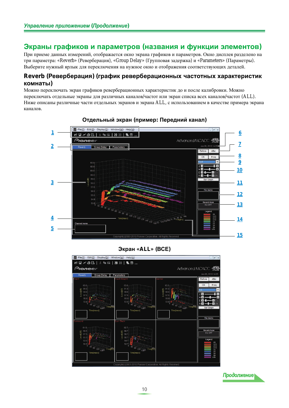
08:55
Pioneer AV Receiver (VSX 1020-K): Unboxing and Tour
00:53
How to Factory Reset Pioneer VSX-1020 7.1 HDMI Home Theater Surround Receiver
02:46
Pioneer VSX-1020-K Review
03:35
Pioneer VSX-1020 7.1 HDMI Home Theater Surround Receiver
04:30
Pioneer vsx-1020 multi-channel receiver
02:56
Pioneer VSX 1020 K Review
02:21
Court demo du Pioneer VSX-1020-K
08:55
Pioneer AV Receiver VSX 1020-K Unboxing and Tour
Нажмите на кнопку для помощи

AUDIO/VIDEO MULTI-CHANNEL RECEIVER
RECEPTOR MULTICANAL DE AUDIO/VÍDEO
VSX-1020
· Protect your new investment
The details of your purchase will be on file for reference in the event of an
insurance claim such as loss or theft.
· Improve product development
Your input helps us continue to design products that meet your needs.
· Receive a free Pioneer newsletter
Registered customers can opt in to receive a monthly newsletter.
· Receive free tips, updates and service bulletins on
your new product
Operating Instructions
Manual de instrucciones
Register your product on
http://www.pioneerelectronics.com (US)
http://www.pioneerelectronics.ca (Canada)
VSX-1020_UC.book 1 ページ 2010年1月7日 木曜日 午後6時0分
- Инструкции и руководства
- Бренды
- Pioneer
- VSX-1020
Справочник Пользователя (Français)
Справочник Пользователя
Содержание
-
Table des matières
4
-
Organigramme des réglages sur le récepteur
7
-
-
Les couleurs des étapes ont la signification suivante :
7
-
1 Avant de commencer
7
-
j
7
-
2 Détermination des enceintes à utiliser (page 15)
7
-
-
j
7
-
3 Raccordement des enceintes
7
-
-
j
7
-
4 Raccordement des composants
7
-
-
j
7
-
5 Mise sous tension
7
-
-
j
7
-
6 Changement de la langue de l’affichage sur écran (OSD Language) (page 37)
7
-
-
j
7
-
7 Réglages des enceintes MCACC
7
-
-
j
7
-
8 Le menu Input Setup (page 40)
7
-
-
j
7
-
9 Lecture de base (page 42)
7
-
-
j
7
-
10 Réglage de la qualité du son et de l’image selon ses préférences
7
-
-
j
7
-
11 Autres ajustements et réglages facultatifs
7
-
-
j
7
-
12 Utilisation optimale de la télécommande
7
-
-
-
Avant de commencer
8
-
Vérification des accessoires livrés avec l’appareil
8
-
Installation du récepteur
8
-
Mise en place des piles
8
-
ATTENTION
8
-
-
-
Commandes et affichages
9
-
Panneau frontal
9
-
1 Cadran INPUT SELECTOR
9
-
2 u STANDBY/ON
9
-
3 SPEAKERS
9
-
4 Capteur
9
-
5 Commandes MULTI-ZONE
9
-
6 Écran à caractères
9
-
7 Voyants
9
-
8 Commandes du syntoniseur
9
-
9 Cadran MASTER VOLUME
9
-
10 Prise PHONES
10
-
11 Touches de mode d’écoute
10
-
12 iPod iPhone DIRECT CONTROL
10
-
13 Prise MCACC SETUP MIC
10
-
14 Prises iPod/iPhone/USB
10
-
15 Prise d’entrée HDMI
10
-
-
Affichage
10
-
1 Indicateurs de SIGNAL
10
-
2 Indicateurs de format de programme
10
-
3 Voyants des formats numériques
10
-
4 MULTI-ZONE
11
-
5 SOUND
11
-
6 S.RTRV
11
-
7 Indicateurs de mode d’écoute
11
-
8 (PHASE CONTROL)
11
-
9 Indicateurs de signal analogique
11
-
10 Voyants du syntoniseur
11
-
12 Niveau du volume général
11
-
13 Indicateurs de fonction d’entrée
11
-
14 Indicateurs de défilement
11
-
15 Indicateur d’enceinte
11
-
16 SLEEP
11
-
17 Indicateurs de format de décodage matrice
11
-
18 Écran à caractères
11
-
19 Indicateur du mode de commande à distance
11
-
-
Télécommande
12
-
La télécommande présente les deux codes couleurs suivants, selon le composant utilisé :
12
-
1 u RECEIVER
12
-
2 MULTI OPERATION — Cette touche permet d’effectuer des opérations multiples (page 80).
12
-
-
3 Touches de fonction d’entrée
12
-
4 ZONE 2
12
-
5 Touches TV CONTROL
12
-
6 Commandes du récepteur
12
-
7 i/j/k/l, ENTER
12
-
8 Commandes du récepteur
13
-
9 Commandes LISTENING MODE
13
-
10 Témoin de télécommande
13
-
11 TV CTRL
13
-
13 MASTER VOLUME +/-
13
-
14 MUTE
13
-
Portée de la télécommande
13
-
-
-
Raccordement de votre équipement
14
-
Ce récepteur vous offre de nombreuses possibilités de liaisons, ce qui ne signifie pas nécessairement que cela soit compliqué. Cette page explique les différents types de composants que vous pouvez raccorder pour réaliser votre système de home cinéma.
14
-
Panneau arrière
14
-
ATTENTION
14
-
Important
14
-
COAX-1
14
-
IN 1
14
-
(BD)
14
-
OPT-1
14
-
OPT-2
14
-
IN 2
14
-
(HDMI-1)
14
-
(HDMI-2)
14
-
(HDMI-3)
14
-
(HDMI-4)
14
-
(HDMI-5)
14
-
COAX-2
14
-
-
-
Détermination des enceintes à utiliser
15
-
[A] Système surround à 9.1 canaux (surround avant-haut)
15
-
-
*Réglage par défaut
15
-
[B] Système surround à 9.1 canaux (surround avant large)
15
-
[C] Système surround à 7.1 canaux et connexion enceintes B
15
-
[D] Système surround à 5.1 canaux et connexion d’enceintes avant Bi-amping (surround haute qualité)
16
-
[E] Système surround à 5.1 canaux et connexion ZONE 2 (multizone)
16
-
Important
16
-
-
Autres liaisons d’enceintes
16
-
Installation des enceintes
17
-
Quelques conseils pour améliorer la qualité du son
17
-
Raccordement des enceintes
18
-
ATTENTION
18
-
Branchement des fils nus
18
-
-
-
Bornes d’enceintes A :
18
-
1 Torsadez ensemble les brins de fil dénudés.
18
-
2 Libérez la borne de l’enceinte et insérez-y le fil.
18
-
3 Refermez la borne.
18
-
-
Bornes d’enceintes B :
18
-
1 Torsadez ensemble les brins de fil dénudés.
18
-
2 Poussez sur les languettes pour les ouvrir et insérez le fil dénudé.
18
-
3 Relâchez les languettes.
18
-
Raccordement avec des fiches banane
18
-
-
(Bornes d’enceintes A uniquement)
18
-
Important
18
-
ATTENTION
18
-
Installation de votre système d’enceintes
19
-
Les enceintes avant gauche et droite sont les seules obligatoires. Notez que vos enceintes surround principales doivent toujours…
19
-
Double amplification des enceintes
20
-
ATTENTION
20
-
-
Double câblage de vos enceintes
20
-
. Pour le double câblage d’une enceinte, raccordez deux cordons d’enceinte à la borne d’enceinte sur le récepteur.
20
-
ATTENTION
20
-
-
-
Sélection d’un Speaker System
21
-
Configuration enceintes avant-haut
21
-
-
-
*Réglage par défaut
21
-
1 Raccordez une paire d’enceintes aux bornes d’enceintes avant-haut.
21
-
2 Si nécessaire, sélectionnez l’option ‘Normal(SB/FH)’ dans le menu Speaker System.
21
-
Configuration enceintes avant-large
21
-
1 Raccordez une paire d’enceintes aux bornes d’enceintes avant-haut.
21
-
2 Sélectionnez ‘Normal(SB/FW)’ sur le menu Speaker System.
21
-
-
Réglage pour les enceintes B
21
-
1 Raccordez une paire d’enceintes aux bornes d’enceintes avant-haut.
21
-
2 Sélectionnez ‘Speaker B’ sur le menu Speaker System.
21
-
-
Réglage pour la double amplification
21
-
1 Raccordez des enceintes compatibles avec la double amplification aux bornes d’enceintes avant et surround arrière.
21
-
2 Sélectionnez ‘Front Bi-Amp’ sur le menu Speaker System.
21
-
-
Réglage pour la ZONE 2
21
-
1 Raccordez une paire d’enceintes aux bornes d’enceintes surround arrière.
21
-
2 Sélectionnez ‘ZONE 2’ sur le menu Speaker System.
21
-
-
À propos de la liaison audio
22
-
HDMI
22
-
-
Audio HD
22
-
Numérique (Coaxial)
22
-
-
Audio numérique conventionnel
22
-
Numérique (Optique)
22
-
RCA (Analogique)
22
-
(Blanc/Rouge)
22
-
-
Audio analogique conventionnel
22
-
ATTENTION
22
-
À propos du convertisseur vidéo
22
-
Raccordement d’un téléviseur ou de lecteurs
23
-
Connexion au moyen de l’interface HDMI
23
-
Si vous avez un composant équipé d’une prise HDMI ou DVI (avec HDCP) (BD : Lecteur de disque Blu-ray, etc.), vous pouvez le raccorder à ce récepteur à l’aide d’un câble HDMI disponible dans le commerce.
23
-
Si le téléviseur et les équipements de lecture connectés prennent en charge la fonction Control HDMI, cette fonction pratique peut être utilisée (consultez la section Fonction Control HDMI, page 62).
23
-
À propos de HDMI
24
-
-
-
-
-
HDMI, le logo HDMI et High-Definition Multimedia Interface sont des marques commerciales ou des marques déposées de HDMI Licensing, LLC aux États-Unis et dans d’autres pays.
24
-
“x.v.Color” et le logo x.v.Color sont des marques commerciales de Sony Corporation.
24
-
Raccordement d’un lecteur DVD sans sortie HDMI
25
-
Le schéma montre comment raccorder un téléviseur (avec entrée HDMI) et un lecteur DVD (ou un autre lecteur sans entrée HDMI) au récepteur.
25
-
. Si vous voulez écouter le son du téléviseur par le récepteur, raccordez le récepteur et le téléviseur à l’aide de câbles audio.
25
-
-
-
Raccordement d’un téléviseur sans entrée HDMI
26
-
Le schéma montre comment raccorder un téléviseur (sans entrée HDMI) et un lecteur DVD (ou un autre lecteur) au récepteur.
26
-
. Avec ces liaisons, le signal vidéo n’est pas transmis au téléviseur même si le lecteur DVD est raccordé à l’aide d’un câble HDMI. Raccordez la prise vidéo du lecteur DVD à l’aide d’un cordon composite ou à composantes.
26
-
. Raccordez les appareils à l’aide d’un câble HDMI pour écouter le son HD par le récepteur. N’utilisez pas de câble HDMI pour transmettre les signaux vidéo.
26
-
Selon le composant vidéo, il peut être impossible de transmettre simultanément des signaux par la liaison HDMI et par d’autres p…
26
-
-
-
Connexion d’un récepteur satellite/câble ou d’un autre boîtier décodeur
27
-
Raccordement d’un enregistreur HDD/DVD, d’un magnétoscope et d’autres sources vidéo
27
-
Raccordement d’autres appareils audio
28
-
À propos du décodeur WMA9 Pro
28
-
-
Raccordement des antennes AM/FM
29
-
1 Retirez les écrans de protection des deux fils d’antenne AM.
29
-
2 Poussez sur les languettes pour les ouvrir, puis insérez complètement un fil dans chaque borne avant de relâcher les languettes pour mettre en place les fils de l’antenne AM.
29
-
3 Reliez l’antenne cadre AM au pied joint.
29
-
4 Placez l’antenne AM sur une surface plane en l’orientant vers une direction qui offre la meilleure réception.
29
-
5 Raccordez l’antenne filaire FM à la prise d’antenne FM.
29
-
Connexion d’antennes extérieures
29
-
-
Configuration MULTI-ZONE
30
-
Réalisation des raccordements MULTI- ZONE
30
-
Options d’écoute MULTI-ZONE
30
-
Configuration de base MULTI-ZONE (ZONE 2)
30
-
1 Raccordez un second amplificateur aux prises AUDIO ZONE 2 OUT et un écran de télévision à la prise VIDEO ZONE 2 OUT, sur ce récepteur.
30
-
2 Raccordez une paire d’enceintes à l’amplificateur de la zone secondaire.
30
-
-
Configuration MULTI-ZONE au moyen des bornes d’enceintes (ZONE 2)
30
-
1 Raccordez une paire d’enceintes aux bornes d’enceintes surround arrière de cet appareil.
30
-
2 Raccordez un téléviseur aux prises VIDEO ZONE 2 OUT à l’arrière de ce récepteur.
30
-
-
-
-
Raccordement de l’ADAPTATEUR Bluetooth optionnel
31
-
. Mettez l’appareil en mode veille et connectez la clé ADAPTATEUR Bluetooth à la borne ADAPTER PORT.
31
-
Important
31
-
-
Raccordement d’un tuner SiriusConnect™
31
-
Raccordement au réseau par l’interface LAN
32
-
Caractéristiques techniques d’une borne LAN
32
-
-
Raccordement d’un composant pourvu d’une prise HDMI à l’entrée du panneau avant
32
-
Connexion d’un iPod
33
-
. Mettez ce récepteur en veille et utilisez le câble d’iPod fourni pour raccorder votre iPod à la prise iPod/iPhone/USB sur le panneau avant de ce récepteur.
33
-
-
Raccordement d’un appareil USB
33
-
. Mettez ce récepteur en veille et raccordez votre appareil USB à la prise iPod/iPhone/USB sur le panneau avant de ce récepteur.
33
-
-
Connexion d’un périphérique USB pour enregistrer les paramètres Advanced MCACC
34
-
Raccordement d’un récepteur infrarouge
35
-
1 Raccordez le capteur du récepteur infrarouge à la prise IR IN à l’arrière de ce récepteur.
35
-
2 Reliez la prise IR IN de l’autre composant à la prise IR OUT à l’arrière de ce récepteur pour établir une liaison avec le récepteur infrarouge.
35
-
-
Fonctionnement d’autres composants Pioneer avec le capteur de cette unité
35
-
Important
35
-
1 Choisissez le capteur de la télécommande du composant que vous souhaitez utiliser.
36
-
2 Reliez la prise CONTROL OUT de ce composant à la prise CONTROL IN d’un autre composant Pioneer.
36
-
-
Branchement du récepteur
36
-
. Branchez le cordon d’alimentation secteur sur une prise secteur pratique.
36
-
ATTENTION
36
-
-
-
-
Configuration de base
37
-
Changement de la langue de l’affichage sur écran (OSD Language)
37
-
1 Allumez le récepteur et votre téléviseur.
37
-
2 Appuyez sur de la télécommande, puis sur HOME MENU.
37
-
3 Sélectionnez ‘System Setup’ sur la page Home Menu.
37
-
4 Sélectionnez ‘OSD Language’ sur le menu System Setup.
37
-
5 Sélectionnez la langue souhaitée.
37
-
6 Sélectionnez ‘OK’ pour changer la langue.
37
-
-
Configuration automatique du son surround (MCACC automatique)
37
-
Important
37
-
ATTENTION
37
-
THX®
37
-
1 Allumez le récepteur et votre téléviseur.
38
-
2 Connectez le microphone à la prise MCACC SETUP MIC sur le panneau avant.
38
-
3 Sélectionnez les paramètres que vous voulez régler.
38
-
4 Appuyez sur puis sélectionnez START.
39
-
-
5 Suivez les instructions affichées à l’écran.
39
-
6 Attendez la fin des tonalités de test, puis confirmez la configuration des enceintes sur l’écran GUI.
39
-
7 Assurez-vous que ‘OK’ est sélectionné, puis appuyez sur ENTER.
39
-
8 La configuration MCACC automatique est terminée et le menu Home Menu réapparaît automatiquement.
40
-
-
-
Problèmes lors de l’utilisation de la configuration MCACC automatique
40
-
-
Le menu Input Setup
40
-
1 Allumez le récepteur et votre téléviseur.
40
-
2 Appuyez sur de la télécommande, puis sur HOME MENU.
40
-
-
3 Sélectionnez ‘System Setup’ sur la page Home Menu.
40
-
4 Sélectionnez ‘Input Setup’ sur le menu System Setup.
40
-
5 Sélectionnez la fonction d’entrée que vous souhaitez configurer.
40
-
6 Sélectionnez la (les) entrée(s) à laquelle (auxquelles) vous avez connecté votre composant.
41
-
7 Lorsque vous avez terminé, procédez au réglage des autres entrées.
41
-
8 Lorsque vous avez terminé, appuyez sur RETURN.
41
-
Réglages possibles et par défaut de la fonction d’entrée
41
-
COAX-1
41
-
IN 1
41
-
OPT-1
41
-
OPT-2
41
-
IN 2
41
-
(HDMI-1)
41
-
(HDMI-2)
41
-
(HDMI-3)
41
-
(HDMI-4)
41
-
(HDMI-5)
41
-
COAX-2
41
-
-
-
-
Lecture de base
42
-
Lecture d’une source
42
-
1 Allumez les composants de votre système et votre récepteur.
42
-
2 Sélectionnez la fonction d’entrée que vous souhaitez lire.
42
-
3 Appuyez sur , puis appuyez sur AUTO/ALC/DIRECT (AUTO SURR/ALC/ STREAM DIRECT) pour sélectionner AUTO SURROUND, puis lancez la lecture de la source.
42
-
-
4 Utilisez la commande du volume pour régler le niveau de celui-ci.
42
-
Lecture d’une source avec une liaison HDMI
43
-
. Utilisez INPUT SELECT pour sélectionner l’entrée HDMI que vous avez raccordée (par exemple, HDMI 1).
43
-
-
-
Lecture d’un iPod
43
-
1 Allumez le récepteur et votre téléviseur.
43
-
2 Appuyez sur iPod USB de la télécommande pour mettre le récepteur en mode iPod/USB.
43
-
Lecture de fichiers stockés sur un iPod
43
-
Recherche des morceaux à écouter
44
-
1 Utilisez les touches i/j pour sélectionner l’option ‘Musique’ dans le menu principal de l’iPod.
44
-
2 Utilisez i/j pour sélectionner une catégorie, puis appuyez sur ENTER pour naviguer dans cette catégorie.
44
-
3 Utilisez i/j pour naviguer dans la catégorie sélectionnée (par exemple, albums).
44
-
4 Poursuivez votre navigation jusqu’à atteindre les éléments que vous souhaitez lire, puis appuyez sur d pour lancer la lecture.
44
-
Astuce
44
-
-
-
Commandes de lecture de base
44
-
Commutation des commandes de l’iPod
44
-
1 Appuyez sur iPod CTRL pour passer aux commandes de l’iPod.
44
-
2 Appuyez une nouvelle fois sur iPod CTRL pour revenir aux commandes du récepteur.
44
-
Astuce
44
-
-
-
-
-
Lecture d’un appareil USB
45
-
1 Allumez le récepteur et votre téléviseur.
45
-
2 Appuyez sur iPod USB de la télécommande pour mettre le récepteur en mode iPod/USB.
45
-
Important
45
-
-
Lecture des fichiers audio enregistrés sur un appareil USB
45
-
1 Utilisez i/j pour sélectionner ‘Music’ sur le menu USB Top.
45
-
2 Utilisez i/j pour sélectionner un dossier, puis appuyez sur ENTER pour naviguer dans ce dossier.
45
-
3 Continuez à naviguer jusqu’à ce que vous arriviez au morceau à écouter, puis appuyez sur d pour commencer la lecture.
45
-
-
Commandes de lecture de base
45
-
-
Lecture des fichiers photo enregistrés sur l’appareil USB
46
-
1 Utilisez i/j pour sélectionner ‘Photos’ sur le menu USB Top.
46
-
2 Utilisez i/j pour sélectionner un dossier, puis appuyez sur ENTER pour naviguer dans ce dossier.
46
-
3 Continuez à naviguer jusqu’à ce que vous arriviez au morceau à écouter, puis appuyez sur d pour commencer la lecture.
46
-
-
Commandes de lecture de base
46
-
Réglage du diaporama
46
-
1 Utilisez i/j pour sélectionner ‘Slideshow Setup’ sur le menu USB Top.
46
-
2 Sélectionnez le réglage souhaité.
46
-
3 Lorsque vous avez terminé, appuyez sur RETURN.
46
-
-
-
À propos des formats de fichiers lisibles
47
-
La fonction USB de ce récepteur prend en charge les formats de fichiers suivants. Notez que certains formats de fichiers ne sont pas disponibles pour la lecture bien qu’ils figurent comme formats de fichiers lisibles.
47
-
Fichiers de musique
47
-
Fichiers photos
47
-
-
-
Pour écouter la radio
48
-
1 Appuyez sur TUNER pour sélectionner le syntoniseur.
48
-
2 Utilisez BAND pour changer la bande (FM ou AM), si nécessaire.
48
-
3 Pour régler une station de radio.
48
-
Amélioration du son FM
48
-
Utilisation de Neural Surround
48
-
Réglage direct d’une station
48
-
1 Appuyez sur TUNER pour sélectionner le syntoniseur.
48
-
2 Utilisez BAND pour changer la bande (FM ou AM), si nécessaire.
48
-
3 Appuyez sur D.ACCESS (Direct Access).
48
-
4 Utilisez les touches numériques pour saisir la fréquence de la station radio.
48
-
-
Mémorisation de stations préréglées
48
-
1 Réglez une station que vous souhaitez mémoriser.
49
-
2 Appuyez sur T.EDIT (TUNER EDIT).
49
-
3 Appuyez sur CLASS pour sélectionner l’une des sept classes, puis appuyez sur PRESET k/l pour sélectionner la station préréglée souhaitée.
49
-
4 Appuyez sur la touche ENTER.
49
-
-
Nommer des stations préréglées
49
-
1 Choisissez la station préréglée que vous désirez nommer.
49
-
2 Appuyez sur T.EDIT (TUNER EDIT).
49
-
3 Saisissez le nom que vous désirez donner à la station.
49
-
Astuce
49
-
-
-
Pour écouter les stations préréglées
49
-
1 Appuyez sur TUNER pour sélectionner le syntoniseur.
49
-
2 Appuyez sur CLASS pour sélectionner la classe où enregistrer la station.
49
-
3 Appuyez sur PRESET k/l pour sélectionner la station préréglée de votre choix.
49
-
-
-
ADAPTATEUR Bluetooth® pour profiter de la musique sans fil
50
-
Lecture de musique sans fil
50
-
Fonctionnement par télécommande
50
-
-
Appairage de l’ADAPTATEUR Bluetooth et d’un périphérique à technologie sans fil Bluetooth
50
-
1 Appuyez sur , puis sur HOME MENU.
50
-
2 Sélectionnez ‘System Setup’, puis appuyez sur ENTER.
51
-
3 Sélectionnez ‘Other Setup’, puis appuyez sur ENTER.
51
-
4 Sélectionnez ‘Pairing Bluetooth Device’, puis appuyez sur ENTER.
51
-
5 Sélectionnez le réglage ‘Passcode’ souhaité.
51
-
6 Si vous avez sélectionné Others (autres) à l’étape 5, entrez le code d’accès.
51
-
7 Suivez les instructions affichées sur l’interface utilisateur pour effectuer l’association de l’appareil avec l’équipement sans fil Bluetooth voulu.
51
-
8 Vérifiez que l’ADAPTATEUR Bluetooth est détecté par le périphérique à technologie sans fil Bluetooth.
51
-
-
-
Lorsque le périphérique à technologie sans fil Bluetooth est raccordé :
51
-
Si le périphérique sans fil Bluetooth n’est pas connecté :
51
-
9 Dans la liste des périphériques sans fil Bluetooth, sélectionnez la clé Bluetooth ADAPTER et entrez le code d’accès choisi à l’étape 5.
51
-
Écoute de contenus musicaux d’un périphérique à technologie sans fil Bluetooth avec votre système
51
-
1 Appuyez sur la touche ADAPTER de la télécommande pour sélectionner le mode d’entrée ADAPTER PORT sur l’appareil.
51
-
2 Effectuez la procédure de connexion du périphérique sans fil Bluetooth vers la clé Bluetooth ADAPTER.
51
-
3 Lancez la lecture des contenus musicaux mémorisés sur le périphérique à technologie sans fil Bluetooth.
51
-
-
Écoute des stations radio Internet
52
-
Important
52
-
1 Appuyez sur NET RADIO pour sélectionner la source radio Internet.
52
-
-
2 Utilisez les touches i/j pour sélectionner la station radio Internet voulue, puis appuyez sur ENTER.
52
-
Programmation des stations de radio Internet
52
-
Programmation à l’aide de l’interface utilisateur
52
-
1 Appuyez sur TOP MENU lorsque la liste des stations de radio Internet est affichée.
52
-
2 Utilisez les touches i/j pour sélectionner la liste des stations de radio Internet que vous souhaitez éditer, puis appuyez sur ENTER.
52
-
3 Utilisez les touches k/l pour sélectionner “Edit“.
52
-
4 Entrez l’adresse Web (URL) de la station radio que vous souhaitez ajouter à la liste.
53
-
-
5 Entrez le titre voulu pour la station de radio Internet.
53
-
-
Programmation depuis un ordinateur
53
-
1 Démarrez l’ordinateur et lancez un navigateur Internet.
53
-
2 Dans la barre d’adresse du navigateur, entrez l’adresse IP attribuée à l’appareil.
53
-
3 Entrez le titre et l’adresse Web (URL) de la station radio que vous souhaitez ajouter à la liste, puis cliquez sur ‘Update’ (mettre à jour).
53
-
Important
53
-
-
-
-
-
Écoute de la radio satellite
53
-
. Appuyez sur SIRIUS pour sélectionner l’entrée SIRIUS.
54
-
Écoute d’une émission SIRIUS Radio
54
-
Sélection de canaux et recherche par genre
54
-
. Appuyez sur i/j pour accéder au guide des canaux SIRIUS et utilisez les touches i/j pour naviguer sur les canaux, puis appuyez sur ENTER pour écouter l’émission SIRIUS Radio.
54
-
Astuce
54
-
-
-
Mémorisation des stations présélectionnées
55
-
1 Sélectionnez la station que vous souhaitez mettre en mémoire.
55
-
2 Appuyez sur la touche T.EDIT.
55
-
3 Appuyez sur CLASS pour sélectionner l’une des sept classes, puis sur k/l pour sélectionner le canal préréglé choisi.
55
-
4 Appuyez sur la touche ENTER.
55
-
Astuce
55
-
-
Écoute des stations présélectionnées
55
-
1 Appuyez sur CLASS pour sélectionner la classe dans laquelle le canal est mémorisé.
55
-
2 Appuyez sur k/l pour sélectionner la présélection désirée.
55
-
-
-
Utilisation du Menu SIRIUS
55
-
1 Appuyez sur la touche TOP MENU.
55
-
2 Utilisez i/j pour sélectionner l’élément du menu, puis appuyez sur ENTER.
55
-
3 Lorsque vous avez terminé, appuyez sur la touche TOP MENU pour revenir à l’écran de réception.
55
-
-
-
-
-
Écoute de sources à l’aide de votre système
56
-
Important
56
-
Lecture en mode Auto
56
-
. Pendant la lecture d’une source, appuyez sur , puis sur AUTO/ALC/DIRECT pour lancer la lecture automatique d’une source.
56
-
Astuce
56
-
-
Écoute d’une source en son surround
56
-
Son surround standard
56
-
. Pendant l’écoute d’une source, appuyez sur , puis appuyez sur STANDARD.
57
-
-
Utilisation des effets surround avancés
58
-
. Appuyez sur , puis appuyez sur ADV SURR (ADV SURROUND) pour sélectionner un mode d’écoute.
58
-
Astuce
58
-
-
-
Écoute en mode stéréo
58
-
. Pendant l’écoute d’une source, appuyez sur , puis sur STEREO pour la lecture en stéréo.
58
-
-
Utilisation de la fonction Front Stage Surround Advance
59
-
. Pendant l’écoute d’une source, appuyez sur , puis appuyez sur STEREO pour sélectionner les modes surround avant évolué.
59
-
-
Utilisation des modes Stream Direct
59
-
. Pendant l’écoute d’une source, appuyez sur , puis appuyez sur AUTO/ALC/ DIRECT pour sélectionner le mode souhaité.
59
-
-
Sélection des préréglages MCACC
60
-
. Pendant l’écoute d’une source, appuyez sur , puis appuyez sur MCACC.
60
-
-
Choix du signal d’entrée
60
-
. Appuyez sur , puis appuyez sur SIGNAL SEL pour sélectionner le signal d’entrée correspondant au composant source.
60
-
-
Un son meilleur grâce à la fonction Phase Control
61
-
. Appuyez sur puis sur PHASE CTRL (PHASE CONTROL) pour activer la correction de phase.
61
-
-
-
Fonction Control HDMI
62
-
Important
62
-
Connexions pour la fonction Control HDMI
62
-
Important
62
-
-
HDMI Setup
63
-
1 Appuyez sur , puis sur HOME MENU.
63
-
2 Sélectionnez ‘System Setup’, puis appuyez sur ENTER.
63
-
3 Sélectionnez ‘Other Setup’, puis appuyez sur ENTER.
63
-
4 Sélectionnez ‘HDMI Setup’, puis appuyez sur ENTER.
63
-
5 Sélectionnez le réglage ‘Control’ souhaité.
63
-
6 Sélectionnez le réglage ‘Control Mode’ souhaité.
63
-
7 Sélectionnez le réglage ‘Display Power Off’ souhaité.
63
-
8 Lorsque vous avez terminé, appuyez sur HOME MENU.
63
-
-
Avant la synchronisation
64
-
1 Mettez tous les équipements en mode veille.
64
-
2 Mettez tous les équipements sous tension, en terminant par le téléviseur.
64
-
3 Choisir l’entrée HDMI par laquelle le téléviseur est relié à ce récepteur et vous assurer que le signal de sortie vidéo des composants raccordés est indiqué correctement à l’écran.
64
-
4 Vérifier si les composants raccordés aux entrées HDMI sont correctement indiqués.
64
-
-
À propos des opérations synchronisées
64
-
À propos des connexions avec un équipement d’une autre marque prenant en charge la fonction Control HDMI
65
-
-
Réglage de la fonction PQLS
65
-
. Appuyez sur , puis sur PQLS pour sélectionner le réglage PQLS.
65
-
-
Recommandations concernant la fonction Control HDMI
66
-
-
Utilisation d’autres fonctions
67
-
Réglage des options audio
67
-
Important
67
-
1 Appuyez sur , puis sur AUDIO PARAMETER.
67
-
-
2 Utilisez les touches i/j pour sélectionner le paramètre que vous souhaitez ajuster.
67
-
3 Utilisez les touches k/l pour configurer le paramètre sélectionné.
67
-
4 Appuyez sur la touche RETURN pour valider la sélection et quitter le menu.
67
-
M1. MEMORY 1 à M6. MEMORY 6
67
-
Réglage par défaut :
67
-
M1. MEMORY 1
67
-
ON
67
-
OFF
67
-
ON
67
-
OFF
67
-
0,0 à 10,0 (images)
67
-
1 seconde = 30 images (NTSC)
67
-
Réglage par défaut : 0.0
67
-
MID/LDN OFF
67
-
MIDNIGHT ON
67
-
LOUDNESS ON
67
-
BYPASS
67
-
ON
67
-
-6 à +6 (dB)
67
-
Réglage par défaut : 0 (dB)
67
-
-6 à +6 (dB)
68
-
Réglage par défaut : 0 (dB)
68
-
OFF
68
-
ON
68
-
OFF
68
-
ON
68
-
OFF
68
-
FLAT
68
-
UP1/UP2/UP3/UP4
68
-
CH1 — seul le canal 1 est émis
68
-
CH2 — seul le canal 2 est émis
68
-
CH1 CH2 — les deux canaux sont émis sur les enceintes avant
68
-
AUTO
68
-
MAX
68
-
MID
68
-
OFF
68
-
0dB/ -5dB/ -10dB/
68
-
-15dB/ -20dB
68
-
OFF
68
-
0 (dB)
68
-
+6 (dB)
68
-
AMP
68
-
THROUGH
68
-
OFF
68
-
ON
68
-
0 à 7
69
-
Réglage par défaut : 3
69
-
-3 à +3
69
-
Réglage par défaut : 0
69
-
OFF
69
-
ON
69
-
0 à 10
69
-
Réglage par défaut :
69
-
Neo:6 MUSIC : 3
69
-
Neo:6 CINEMA : 10
69
-
10 à 90
69
-
Réglage par défaut : 50
69
-
(90 pour EXT.STEREO seulement)
69
-
LOW
69
-
MID
69
-
HIGH
69
-
OFF
69
-
ON
69
-
OFF
69
-
ON
69
-
-
-
Réglages des options vidéo
70
-
Important
70
-
1 Appuyez sur , puis sur VIDEO PARAMETER.
70
-
-
2 Utilisez les touches i/j pour sélectionner le paramètre que vous souhaitez ajuster.
70
-
3 Utilisez les touches k/l pour configurer le paramètre sélectionné.
70
-
4 Appuyez sur la touche RETURN pour valider la sélection et quitter le menu.
70
-
ON
70
-
OFF
70
-
AUTO
70
-
PURE
70
-
480p/576p
70
-
720p
70
-
1080i
70
-
1080p
70
-
THROUGH
70
-
NORMAL
70
-
AUTO
71
-
ON
71
-
OFF
71
-
-4 à +4
71
-
Réglage par défaut : 0
71
-
0 à +8
71
-
Réglage par défaut : 0
71
-
-4 à +4
71
-
Réglage par défaut : 0
71
-
-4 à +4
71
-
Réglage par défaut : 0
71
-
-6 à +6
71
-
Réglage par défaut : 0
71
-
-6 à +6
71
-
Réglage par défaut : 0
71
-
-6 à +6
71
-
Réglage par défaut : 0
71
-
-6 à +6
71
-
Réglage par défaut : 0
71
-
-
-
Commutation du système d’enceintes
72
-
. Utilisez la touche SPEAKERS du panneau avant pour sélectionner un réglage des bornes d’enceintes.
72
-
-
Utilisation des commandes MULTI-ZONE
72
-
1 Appuyez sur MULTI-ZONE ON/OFF du panneau avant.
72
-
2 Appuyez sur MULTI-ZONE CONTROL du panneau avant.
72
-
3 Utilisez la molette INPUT SELECTOR pour choisir la source pour la zone secondaire.
72
-
4 Lorsque le Speaker System est réglé sur ZONE 2, utilisez le bouton de volume principal MASTER VOLUME pour régler le volume des enceintes de la zone secondaire.
73
-
-
5 Lorsque vous avez terminé, appuyez de nouveau sur MULTI-ZONE CONTROL pour retourner aux commandes de la zone principale.
73
-
Télécommandes MULTI-ZONE
73
-
-
Faire un enregistrement audio ou vidéo
73
-
1 Sélectionnez la source que vous désirez enregistrer.
73
-
2 Préparez la source que vous désirez enregistrer.
73
-
3 Préparez l’appareil enregistreur.
74
-
4 Lancez l’enregistrement, puis lancez la lecture de la source.
74
-
-
Réduction du niveau d’un signal analogique
74
-
. Appuyez sur , puis appuyez sur A.ATT pour activer et désactiver l’atténuateur.
74
-
-
Utilisation de la minuterie sommeil
74
-
. Appuyez sur , puis plusieurs fois de suite sur SLEEP pour régler le délai de mise en veille.
74
-
-
Réduction de la luminosité de l’écran
74
-
. Appuyez sur , puis appuyez plusieurs fois de suite sur DIMMER pour changer la luminosité de l’affichage sur le panneau avant.
74
-
-
Vérification des réglages de votre système
74
-
1 Appuyez sur , puis sur STATUS pour vérifier les réglages du système.
74
-
Source d’entrée
74
-
Fréquence d’échantillonnage
74
-
Préréglage MCACC
74
-
Entrée ZONE 2
74
-
2 Lorsque vous avez terminé, appuyez à nouveau sur STATUS pour quitter cet écran.
74
-
-
Réinitialisation du système
75
-
1 Mettez le récepteur en mode de veille.
75
-
2 Tout en tenant ENTER enfoncée sur le panneau avant, appuyez sur u STANDBY/ ON.
75
-
3 Sélectionnez ‘RESET’ avec PRESET k/l, puis appuyez sur ENTER sur le panneau avant.
75
-
4 Appuyez sur ENTER pour confirmer.
75
-
Paramètres du système par défaut
75
-
-
-
Commander le reste de votre système
76
-
Exploitation de plusieurs récepteurs
76
-
1 Appuyez sur la touche R.SETUP sans la relâcher et appuyez sur la touche “4” pendant trois secondes.
76
-
2 Appuyez sur la touche numérotée correspondant à l’appareil (“Receiver 1” à “Receiver 4”) que vous souhaitez commander.
76
-
-
Configurer la télécommande pour commander d’autres composants
76
-
Remarque
76
-
-
Sélectionner directement des codes de préréglage
77
-
1 Appuyez sur la touche R.SETUP sans la relâcher et appuyez sur la touche “1” pendant trois secondes.
77
-
2 Appuyez sur la touche de fonction d’entrée correspondant au composant que vous voulez utiliser.
77
-
3 Utilisez les touches numériques pour introduire le code préréglé à 4 chiffres.
77
-
4 Répétez les étapes 2 à 3 pour les autres composants que vous voulez utiliser.
77
-
5 Pour quitter le mode de configuration du code de préréglage, appuyez sur R.SETUP.
77
-
-
Programmation de signaux depuis d’autres télécommandes
77
-
1 Appuyez sur la touche R.SETUP sans la relâcher et appuyez sur la touche “2” pendant trois secondes.
78
-
2 Appuyez sur la touche de fonction d’entrée correspondant au composant que vous voulez utiliser.
78
-
3 Orientez les deux télécommandes l’une vers l’autre et appuyez sur la touche effectuant l’apprentissage sur la télécommande du récepteur.
78
-
4 Appuyez sur la touche correspondante sur la télécommande qui envoie (enseigne) le signal à la télécommande du récepteur.
78
-
5 Pour programmer d’autres signaux pour le composant actuel, répétez les étapes 3 et 4.
78
-
6 Pour quitter le mode de configuration, appuyez sur R.SETUP.
78
-
-
Effacement d’un réglage de touche de la télécommande
78
-
1 Appuyez sur la touche R.SETUP sans la relâcher et appuyez sur la touche “7” pendant trois secondes.
78
-
2 Appuyez sur la touche de fonction d’entrée correspondant à la commande à effacer, puis appuyez sur ENTER.
78
-
3 Appuyez sur la touche à réinitialiser sans la relâcher pendant trois secondes.
78
-
4 Répétez l’étape 3 pour effacer d’autres touches.
78
-
5 Pour quitter le mode de réinitialisation, appuyez sur R.SETUP.
78
-
-
Réinitialisation des paramètres attribués à une touche de fonction d’entrée
79
-
1 Appuyez sur la touche R.SETUP sans la relâcher et appuyez sur la touche “9” pendant trois secondes.
79
-
2 Appuyez sans relâcher pendant trois secondes sur la touche d’entrée correspondant à la commande à réinitialiser.
79
-
-
Fonction Source directe
79
-
1 Appuyez sur la touche R.SETUP sans la relâcher et appuyez sur la touche “5” pendant trois secondes.
79
-
2 Appuyez sur la touche de fonction d’entrée correspondant au composant que vous voulez utiliser.
79
-
3 Appuyez sur la touche “1” pour activer ou sur la touche “0” pour désactiver la fonction Direct.
79
-
4 Pour quitter le mode de configuration, appuyez sur R.SETUP.
79
-
-
Fonctions Multi operation et System off
80
-
Programmation d’une séquence
80
-
1 Appuyez sur la touche R.SETUP sans la relâcher et appuyez sur la touche “3” pendant trois secondes.
80
-
2 Appuyez sur la touche de fonction d’entrée (ou sur la touche u SOURCE).
80
-
3 Si besoin, appuyez sur la touche de fonction d’entrée pour le composant dont vous souhaitez entrer la commande.
81
-
4 Sélectionnez la touche pour la commande que vous souhaitez entrer.
81
-
5 Répétez les étapes 3 à 4 pour programmer une suite de cinq commandes au maximum.
81
-
-
Utilisation des opérations multiples
81
-
1 Appuyez sur la touche MULTI OPERATION.
81
-
2 Dans un délai de cinq secondes, appuyez sur une touche d’entrée ayant été programmée pour utiliser la fonction Multi operation.
81
-
-
Utilisation de la désactivation système
81
-
1 Appuyez sur la touche MULTI OPERATION.
81
-
2 Dans un délai de cinq secondes, appuyez sur la touche u SOURCE.
81
-
-
Réinitialisation de tous les paramètres de la fonction Multi operation
81
-
1 Appuyez sur la touche R.SETUP sans la relâcher et appuyez sur la touche “8” pendant trois secondes.
81
-
2 Appuyez sur la touche d’entrée (source) correspondant à la séquence programmée que vous souhaitez supprimer ou appuyez sur la touche u SOURCE pendant trois secondes.
81
-
-
-
Suppression de tous les réglages de la télécommande
82
-
1 Appuyez sur la touche R.SETUP sans la relâcher et appuyez sur la touche “0” pendant trois secondes.
82
-
2 Appuyez sur la touche ENTER sans la relâcher pendant trois secondes.
82
-
Codes de préréglages par défaut
82
-
-
Commandes pour autres composants
82
-
b. Commandes de SACD.
84
-
c. Commandes de MD.
84
-
-
Le menu MCACC avancé
85
-
Réglages du récepteur depuis le menu MCACC avancé
85
-
1 Allumez le récepteur et votre téléviseur.
85
-
2 Appuyez sur sur la télécommande, puis sur HOME MENU.
85
-
-
3 Sélectionnez ‘Advanced MCACC’ dans le HOME MENU, puis appuyez sur ENTER.
85
-
4 Sélectionnez le réglage que vous voulez ajuster.
85
-
-
MCACC automatique (Expert)
86
-
Important
86
-
ATTENTION
86
-
1 Sélectionnez ‘Auto MCACC’ dans le Advanced MCACC, puis appuyez sur ENTER.
86
-
2 Sélectionnez les paramètres que vous voulez régler.
86
-
3 Connectez le microphone à la prise MCACC SETUP MIC sur le panneau avant.
87
-
4 Lorsque vous avez terminé de régler les options, sélectionnez START puis appuyez sur ENTER.
87
-
5 Suivez les instructions affichées à l’écran.
87
-
6 Attendez que la configuration MCACC automatique ait fini d’émettre les tonalités de test.
88
-
7 Si besoin, vérifiez la configuration des enceintes sur l’écran GUI.
88
-
8 Assurez-vous que ‘OK’ est sélectionné, puis appuyez sur ENTER.2
88
-
-
9 La configuration MCACC automatique est terminée et le menu Advanced MCACC réapparaît automatiquement.
89
-
-
Configuration MCACC manuelle
89
-
ATTENTION
89
-
Important
89
-
1 Sélectionnez ‘Manual MCACC’ sur le menu Advanced MCACC.
90
-
2 Sélectionnez le réglage que vous voulez ajuster.
90
-
Réglage précis du niveau de canal
90
-
1 Sélectionnez ‘Fine Channel Level’ sur le menu Manual MCACC.
90
-
2 Ajustez le niveau du canal gauche.
90
-
3 Sélectionnez tour à tour chaque canal et ajustez les niveaux (+/-12.0 dB) si besoin.
90
-
4 Lorsque vous avez terminé, appuyez sur RETURN.
91
-
-
Distance précise des enceintes
91
-
1 Sélectionnez ‘Fine SP Distance’ sur le menu Manual MCACC.
91
-
2 Ajustez la distance du canal gauche à partir de la position d’écoute.
91
-
3 Sélectionnez tour à tour chaque canal et ajustez la distance si besoin.
91
-
4 Lorsque vous avez terminé, appuyez sur RETURN.
91
-
-
Ondes stationnaires
91
-
1 Sélectionnez ‘Standing Wave’ sur le menu Manual MCACC.
92
-
2 Ajustez les paramètres de contrôle des ondes stationnaires.
92
-
3 Lorsque vous avez terminé, appuyez sur RETURN.
92
-
-
Réglage de l’égalisation du calibrage acoustique
92
-
1 Sélectionnez ‘EQ Adjust’ sur le menu Manual MCACC.
92
-
2 Sélectionnez le(s) canal(canaux) souhaité(s) et ajustez-les à votre convenance.
92
-
Astuce
93
-
-
3 Lorsque vous avez terminé, appuyez sur RETURN.
93
-
-
Égalisation du calibrage acoustique professionnel
93
-
Comment utiliser l’égalisation du calibrage acoustique professionnel
93
-
Utilisation de l’égalisation du calibrage acoustique professionnel
93
-
1 Sélectionnez ‘EQ Professional’, puis appuyez sur ENTER.
93
-
2 Sélectionnez une option et appuyez sur ENTER.
93
-
3 Si vous avez sélectionné ‘Reverb Measurement’, sélectionnez EQ ON ou OFF, puis START.
94
-
4 Si vous avez sélectionné ‘Reverb View’, vous pouvez vérifier les caractéristiques de la réverbération de chaque canal. Appuyez sur RETURN lorsque vous avez terminé.
94
-
5 Si ‘Advanced EQ Setup’ est sélectionné, spécifiez la mémoire MCACC qui doit être utilisée, puis précisez le réglage de temps souhaité pour le calibrage, et finalement sélectionnez START.
94
-
-
-
-
Vérification des données MCACC
95
-
1 Appuyez sur , puis sur HOME MENU.
95
-
2 Sélectionnez ‘MCACC Data Check’ sur le Home Menu.
95
-
3 Sélectionnez le réglage que vous voulez vérifier.
95
-
4 Appuyez sur RETURN pour revenir au menu MCACC Data Check, en répétant les étapes 2 et 3 pour vérifier d’autres réglages.
95
-
5 Lorsque vous avez terminé, appuyez sur RETURN.
95
-
Réglage des enceintes
95
-
1 Sélectionnez ‘Speaker Setting’ sur le menu MCACC Data Check.
95
-
2 Sélectionnez le canal que vous voulez vérifier.
95
-
-
Niveau des canaux
96
-
1 Sélectionnez ‘Channel Level’ sur le menu MCACC Data Check.
96
-
2 Lorsque ‘MCACC’ est surligné, utilisez k/l pour sélectionner le préréglage MCACC que vous voulez vérifier.
96
-
-
Distance des enceintes
96
-
1 Sélectionnez ‘Speaker Distance’ sur le menu MCACC Data Check.
96
-
2 Lorsque ‘MCACC’ est surligné, utilisez k/l pour sélectionner le préréglage MCACC que vous voulez vérifier.
96
-
-
Ondes stationnaires
96
-
1 Sélectionnez ‘Standing Wave’ sur le menu MCACC Data Check.
96
-
2 Lorsque ‘Filter Channel’ est surligné, utilisez i/j pour sélectionner le canal pour lequel vous voulez vérifiez le contrôle des ondes stationnaires.
96
-
3 Appuyez sur k pour surligner ‘MCACC’, puis utilisez i/j pour sélectionner le préréglage MCACC que vous voulez vérifier.
96
-
-
Égalisation du calibrage acoustique
96
-
1 Sélectionnez ‘Acoustic Cal EQ’ sur le menu MCACC Data Check.
96
-
2 Lorsque ‘Ch’ est surligné, utilisez i/j pour sélectionner le canal.
96
-
3 Appuyez sur k pour surligner ‘MCACC’, puis utilisez i/j pour sélectionner le préréglage MCACC que vous voulez vérifier.
96
-
-
Exportation des données MCACC
96
-
1 Sélectionnez ‘Output MCACC data’ sur le menu MCACC Data Check.
97
-
2 Connectez le périphérique USB à la prise USB sur le panneau frontal de l’appareil, puis sélectionnez “OK”.
97
-
3 Lorsque vous avez terminé, appuyez sur RETURN.
97
-
-
-
Gestion des données
97
-
1 Appuyez sur , puis sur HOME MENU.
97
-
2 Sélectionnez ‘Data Management’ sur la page Home Menu.
97
-
3 Sélectionnez le réglage que vous voulez ajuster.
97
-
Renommer les préréglages MCACC
98
-
1 Sélectionnez ‘Memory Rename’ sur le menu Data Management.
98
-
2 Sélectionnez le préréglage MCACC à renommer, puis choisissez un nom de préréglage approprié.
98
-
3 Répétez l’opération pour chaque préréglage MCACC à renommer, puis appuyez sur RETURN lorsque vous avez terminé.
98
-
-
Copie des données de préréglage MCACC
98
-
1 Sélectionnez ‘MCACC Memory Copy’ sur le menu Data Management.
98
-
2 Sélectionnez le réglage que vous souhaitez copier.
98
-
3 Sélectionnez le préréglage MCACC dont vous allez copier les réglages (‘From’), puis précisez où vous souhaitez les copier (‘To’).
98
-
4 Sélectionnez ‘OK’ pour confirmer la copie des réglages.
98
-
-
Suppression des préréglages MCACC
98
-
1 Sélectionnez ‘MCACC Memory Clear’ sur le menu Data Management.
98
-
2 Sélectionnez le préréglage MCACC que vous voulez supprimer.
98
-
3 Sélectionnez ‘OK’ pour confirmer la suppression du préréglage.
98
-
-
-
-
Le réglage du système et autres réglages
99
-
Réglages du récepteur depuis le menu System Setup
99
-
1 Allumez le récepteur et votre téléviseur.
99
-
2 Appuyez sur , puis sur HOME MENU.
99
-
3 Sélectionnez ‘System Setup’ dans le Home Menu, puis appuyez sur ENTER.
99
-
4 Sélectionnez le réglage que vous voulez ajuster.
99
-
-
Réglage manuel des enceintes
99
-
ATTENTION
99
-
1 Sélectionnez ‘Manual SP Setup’, puis appuyez sur ENTER.
99
-
2 Sélectionnez le réglage que vous voulez ajuster.
100
-
3 Effectuez les mises au point nécessaires pour chaque réglage en appuyant sur RETURN pour confirmer chaque écran.
100
-
Configuration du Speaker System
100
-
1 Sélectionnez ‘Speaker System’ sur le menu Manual SP Setup.
100
-
2 Sélectionnez l’option Speaker System souhaitée.
100
-
3 Si à l’étape 2 vous avez sélectionné l’option Normal(SB/FH), Normal(SB/FW), ou Speaker B, spécifiez l’emplacement des enceintes surround.
100
-
4 Lorsque ‘Setting Change?’ est affiché, sélectionnez Yes.
100
-
-
Réglage des enceintes
101
-
1 Sélectionnez ‘Speaker Setting’ sur le menu Manual SP Setup.
101
-
2 Choisissez le groupe d’enceintes que vous souhaitez régler, puis sélectionnez une taille d’enceinte.
101
-
3 Sélectionnez ‘X. OVER’ et réglez la fréquence de croisement.
102
-
-
4 Lorsque vous avez terminé, appuyez sur RETURN.
102
-
-
Niveau des canaux
102
-
1 Sélectionnez ‘Channel Level’ sur le menu Manual SP Setup.
102
-
2 Réglez le niveau de chaque canal à l’aide des touches k/l.
102
-
3 Lorsque vous avez terminé, appuyez sur RETURN.
102
-
Astuce
102
-
-
-
Distance des enceintes
103
-
1 Sélectionnez ‘Speaker Distance’ sur le menu Manual SP Setup.
103
-
2 Réglez la distance de chaque enceinte à l’aide des touches k/l.
103
-
3 Lorsque vous avez terminé, appuyez sur RETURN.
103
-
Astuce
103
-
-
-
Courbe X
103
-
1 Sélectionnez ‘X-Curve’ sur le menu Manual SP Setup.
103
-
2 Choisissez le réglage de courbe X souhaité.
103
-
Taille de la pièce (pied2)
103
-
Courbe X
103
-
(dB/oct)
103
-
-
3 Lorsque vous avez terminé, appuyez sur RETURN.
103
-
-
-
Menu de configuration réseau
104
-
1 Appuyez sur de la télécommande, puis sur HOME MENU.
104
-
2 Sélectionnez ‘System Setup’ sur la page HOME MENU.
104
-
3 Sélectionnez ‘Network Setup’ sur la page System Setup.
104
-
4 Sélectionnez le réglage que vous voulez ajuster.
104
-
Configuration de l’adresse IP/Proxy
104
-
Astuce
104
-
1 Sélectionnez ‘IP Address, Proxy’ sur le menu Network Setup.
105
-
2 Sélectionnez le réglage DHCP souhaité.
105
-
3 Entrez les IP Address, Subnet Mask, Default Gateway, Primary DNS Server et Secondary DNS Server.
105
-
4 Sélectionnez la valeur ‘OFF’ ou ‘ON’ pour l’option Enable Proxy Server afin de désactiver ou d’activer le serveur proxy.
105
-
5 Désignez l’adresse de votre serveur proxy ou le nom de domaine.
105
-
6 Désignez le numéro de port de votre serveur proxy.
105
-
7 Sélectionnez ‘OK’ pour confirmer la configuration de l’adresse IP/Proxy.
105
-
-
Affichage de l’adresse MAC
105
-
. Sélectionnez ‘Information’ sur le menu Network Setup.
105
-
-
-
Le menu Other Setup
105
-
1 Appuyez sur de la télécommande, puis sur HOME MENU.
105
-
2 Sélectionnez ‘System Setup’ sur la page HOME MENU.
105
-
3 Sélectionnez ‘Other Setup’, puis appuyez sur ENTER.
105
-
4 Sélectionnez le réglage que vous voulez ajuster.
105
-
5 Effectuez les mises au point nécessaires pour chaque réglage en appuyant sur RETURN pour confirmer chaque écran.
105
-
Configuration du volume
105
-
1 Sélectionnez ‘Volume Setup’ sur le menu Other Setup.
106
-
2 Sélectionnez le réglage Power ON Level souhaité.
106
-
3 Sélectionnez le réglage Volume Limit souhaité.
106
-
4 Sélectionnez le réglage Mute Level souhaité.
106
-
5 Lorsque vous avez terminé, appuyez sur RETURN.
106
-
-
Réglage du mode de la télécommande
106
-
1 Sélectionnez ‘Remote Control Mode Setup’ sur le menu Other Setup.
106
-
2 Sélectionnez le réglage Remote Control Mode souhaité.
106
-
3 Sélectionnez “OK” pour changer le mode de commande à distance.
106
-
4 Suivez les instructions apparaissant à l’écran pour changer les réglages de la télécommande.
106
-
5 Lorsque vous avez terminé, appuyez sur RETURN.
106
-
-
Réglage de la réduction du scintillement
106
-
1 Sélectionnez ‘Flicker Reduction Setup’ sur le menu Other Setup.
106
-
2 Sélectionnez le réglage Flicker Reduction souhaité.
106
-
3 Lorsque vous avez terminé, appuyez sur RETURN.
106
-
-
-
-
Informations complémentaires
107
-
Guide de dépannage
107
-
Une utilisation incorrecte de l’appareil est souvent interprétée comme un problème ou un dysfonctionnement. Si vous êtes convain…
107
-
Remarque
107
-
. Si l’unité ne fonctionne pas normalement en raison d’un problème externe aux appareils, comme la présence d’électricité statiq…
107
-
-
Alimentation
107
-
Pas de son
108
-
Autres problèmes audio
109
-
Vidéo
111
-
Réglages
112
-
Graphique de l’égalisation du calibrage professionnel
113
-
Écran
113
-
Télécommande
114
-
HDMI
115
-
Information importante concernant la connexion HDMI
116
-
Configuration A
116
-
Remarque
116
-
-
Configuration B
116
-
Remarque
116
-
-
-
Interface USB
117
-
Radio Internet
118
-
Message de SIRIUS Radio
119
-
-
À propos de l’iPod
119
-
iPod est une marque commerciale d’Apple Inc., enregistrées aux États-Unis et dans d’autres pays. iPhone est une marque commerciale d’Apple Inc.
119
-
À propos de SIRIUS
120
-
Formats de son surround
120
-
Dolby
120
-
DTS
120
-
-
-
Fabriqué sous licence sous couvert des brevets U.S. N : 5,451,942; 5,956,674; 5,974,380; 5,978,762; 6,226,616; 6,487,535; 7,212…
120
-
Windows Media Audio 9 Professional
120
-
-
Windows Media et le logo Windows sont des marques commerciales ou des marques déposées de Microsoft Corporation aux États- Unis et/ou dans d’autres pays.
120
-
Surround automatique, ALC et flux direct avec différents formats de signal d’entrée
121
-
Formats de signal stéréo (2 canaux)
121
-
Dolby Digital Surround
121
-
2 Pro Logic llx MOVIE
121
-
2 Pro Logic llx MOVIE
121
-
DTS Surround
121
-
Neo:6 CINEMA
121
-
Neo:6 CINEMA
121
-
Autres sources stéréo
121
-
Lecture stéréo
121
-
Lecture stéréo
121
-
Sources analogiques
121
-
Comme ci-dessus
121
-
-
ANALOG DIRECT (stéréo)
121
-
Sources PCM
121
-
Comme ci-dessus
121
-
-
PCM DIRECT
121
-
Sources DVD-A
121
-
Comme ci-dessus
121
-
Comme ci-dessus
121
-
-
Sources SACD
121
-
Comme ci-dessus
121
-
Comme ci-dessus
121
-
-
Dolby Digital Surround
121
-
2 Pro Logic ll MOVIE
121
-
2 Pro Logic ll MOVIE
121
-
DTS Surround
121
-
Neo:6 CINEMA
121
-
Neo:6 CINEMA
121
-
Autres sources stéréo
121
-
Lecture stéréo
121
-
Lecture stéréo
121
-
Sources analogiques
121
-
Comme ci-dessus
121
-
-
ANALOG DIRECT (stéréo)
121
-
Sources PCM
121
-
Comme ci-dessus
121
-
-
PCM DIRECT
121
-
Sources DVD-A
121
-
Comme ci-dessus
121
-
Comme ci-dessus
121
-
-
Sources SACD
121
-
Comme ci-dessus
121
-
Comme ci-dessus
121
-
-
-
Formats de signaux multi-canaux
121
-
Dolby Digital EX (Canal 6.1 indiqué)
121
-
Dolby Digital EX
121
-
2 Pro Logic llx MOVIE
121
-
Dolby Digital EX
121
-
2 Pro Logic llx MOVIEa
121
-
DTS-ES (Sources canal 6.1/Canal 6.1 indiqué)
121
-
DTS-ES (Matrice/Discrète)
121
-
DTS-ES (Matrice/Discrète)
121
-
Sources DTS (Codage canal 5.1)
121
-
Décodage linéaire
121
-
Décodage linéaire
121
-
Sources DTS-HD
121
-
Comme ci-dessus
121
-
Comme ci-dessus
121
-
-
Autres sources 5.1/6.1/7.1 canaux
121
-
Comme ci-dessus
121
-
Comme ci-dessus
121
-
-
Sources DVD-A/Multi-ch PCM
121
-
Décodage linéaire
121
-
Décodage linéaire
121
-
Sources SACD (Codage canal 5.1)
121
-
Comme ci-dessus
121
-
Comme ci-dessus
121
-
-
Autres sources 5.1/6.1/7.1 canaux
121
-
Comme ci-dessus
121
-
Comme ci-dessus
121
-
-
-
-
Liste des codes préréglés
122
-
Important
122
-
-
Téléviseur
122
-
Téléviseur
122
-
DVD
123
-
-
Si les commandes ne fonctionnent pas avec les codes de préréglage ci-dessous, essayez d’utiliser les codes de préréglages indiqués pour les produits BD, DVR (BDR, HDR).
123
-
BD
124
-
-
Si les commandes ne fonctionnent pas avec les codes de préréglage ci-dessous, essayez d’utiliser les codes de préréglages indiqués pour les produits DVD, DVR (BDR, HDR).
124
-
DVR (BDR, HDR)
124
-
-
Si les commandes ne fonctionnent pas avec les codes de préréglage ci-dessous, essayez d’utiliser les codes de préréglages indiqués pour les produits DVD, BD.
124
-
Magnétoscope
124
-
Décodeur satellite
125
-
Décodeur satellite (Combiné SAT/PVR)
125
-
Décodeur câble
125
-
Décodeur câble (Combiné Câble/PVR)
126
-
CD
126
-
CD-R
126
-
Lecteur de disque laser
126
-
Platine à cassette
126
-
Platine à cassette numérique
126
-
MD
126
-
Spécifications
127
-
Section amplificateur
127
-
Section audio
127
-
Section syntoniseur
127
-
Section vidéo
127
-
Section Entrée/Sortie numériques
127
-
Section commande intégrée
127
-
Divers
127
-
Numéros des articles fournis
127
-
Remarque
127
-
-
-
Nettoyage de l’appareil
128
-
-
-
-
- Размер:
- 7,7 МБ
-
- Страницы:
- 132
-
- Язык:
- Français
Просмотреть