

AUDIO/VIDEO MULTI-CHANNEL RECEIVER
RECEPTEUR AUDIOVISUEL A
VOIES MULTIPLES
RECEPTOR MULTICANAL DE AUDIO/VÍDEO
VSX-819H
Register your product at:
www.pioneerelectronics.com (US)
www.pioneerelectronics.ca (Canada)
• Protect your new investment
The details of your purchase will be on file for reference in the event of an
insurance claim such as loss or theft.
• Receive free tips, updates and service bulletins on
your new product
• Improve product development
Your input helps us continue to design products that meet your needs.
• Receive a free Pioneer newsletter
Registered customers can opt in to receive a monthly newsletter.
Operating Instructions
Mode d’emploi
Manual de instrucciones

WARNING
This equipment is not waterproof. To prevent a fire
or shock hazard, do not place any container filled
with liquid near this equipment (such as a vase or
flower pot) or expose it to dripping, splashing, rain
or moisture.
WARNING
Before plugging in for the first time, read the following
section carefully.
The voltage of the available power supply differs
according to country or region. Be sure that the
power supply voltage of the area where this unit
will be used meets the required voltage (e.g., 230 V
or 120 V) written on the rear panel.
This product is for general household purposes. Any
failure due to use for other than household purposes
(such as long-term use for business purposes in a
restaurant or use in a car or ship) and which
requires repair will be charged for even during the
warranty period.
D3-4-2-1-3_B_En
D3-4-2-1-4_A_En
K041_En
If the AC plug of this unit does not match the AC
outlet you want to use, the plug must be removed
and appropriate one fitted. Replacement and
mounting of an AC plug on the power supply cord of
this unit should be performed only by qualified
service personnel. If connected to an AC outlet, the
cut-off plug can cause severe electrical shock. Make
sure it is properly disposed of after removal.
The equipment should be disconnected by removing
the mains plug from the wall socket when left
unused for a long period of time (for example, when
on vacation).
D3-4-2-2-1a_A_En
WARNING: Handling the cord on this product or
cords associated with accessories sold with the
product will expose you to chemicals listed on
proposition 65 known to the State of California and
other governmental entities to cause cancer and
birth defect or other reproductive harm.
Wash hands after handling
D36-P4_A_En
IMPORTANT NOTICE – THE SERIAL NUMBER FOR THIS EQUIPMENT IS LOCATED IN THE REAR.
PLEASE WRITE THIS SERIAL NUMBER ON YOUR ENCLOSED WARRANTY CARD AND
KEEP IN A SECURE AREA. THIS IS FOR YOUR SECURITY.
D1-4-2-6-1_En
NOTE: This equipment has been tested and found to comply with the limits for a Class B digital device, pursuant to
Part 15 of the FCC Rules. These limits are designed to provide reasonable protection against harmful interference in
a residential installation. This equipment generates, uses, and can radiate radio frequency energy and, if not
installed and used in accordance with the instructions, may cause harmful interference to radio communications.
However, there is no guarantee that interference will not occur in a particular installation. If this equipment does
cause harmful interference to radio or television reception, which can be determined by turning the equipment off
and on, the user is encouraged to try to correct the interference by one or more of the following measures:
– Reorient or relocate the receiving antenna.
– Increase the separation between the equipment and receiver.
– Connect the equipment into an outlet on a circuit different from that to which the receiver is connected.
– Consult the dealer or an experienced radio/TV technician for help.
D8-10-1-2_En
This Class B digital apparatus complies with Canadian ICES-003.
Cet appareil numérique de la Classe B est conforme à la norme NMB-003 du Canada.
D8-10-1-3_EF
Information to User
Alterations or modifications carried out without appropriate authorization may invalidate the user’s right to operate
the equipment.
D8-10-2_En
CAUTION: This product satisfies FCC regulations when shielded cables and connectors are used to connect the
unit to other equipment. To prevent electromagnetic interference with electric appliances such as radios and
televisions, use shielded cables and connectors for connections.
D8-10-3a_En
FEDERAL COMMUNICATIONS COMMISSION DECLARATION OF CONFORMITY
This device complies with part 15 of the FCC Rules. Operation is subject to the following two conditions: (1) This
device may not cause harmful interference, and (2) this device must accept any interference received, including
interference that may cause undesired operation.
Product Name: AUDIO/VIDEO MULTI-CHANNEL RECEIVER
Model Number: VSX-819H-K
Responsible Party Name: PIONEER ELECTRONICS SERVICE, INC.
Address: 1925 E. DOMINGUEZ ST. LONG BEACH, CA 90801-1760, U.S.A.
Phone: 1-800-421-1404
IMPORTANT
The lightning flash with arrowhead symbol,
within an equilateral triangle, is intended to
alert the user to the presence of uninsulated
«dangerous voltage» within the product’s
enclosure that may be of sufficient
magnitude to constitute a risk of electric
shock to persons.
Read these instructions.
1)
Keep these instructions.
2)
Heed all warnings.
3)
Follow all instructions.
4)
Do not use this apparatus near water.
5)
Clean only with dry cloth.
6)
Do not block any ventilation openings. Install in
7)
accordance with the manufacturer’s instructions.
Do not install near any heat sources such as

radiators, heat registers, stoves, or other apparatus
(including amplifiers) that produce heat.
Do not defeat the safety purpose of the polarized or
9)
grounding-type plug. A polarized plug has two
blades with one wider than the other. A grounding
type plug has two blades and a third grounding
prong. The wide blade or the third prong are
provided for your safety. If the provided plug does
not fit into your outlet, consult an electrician for
replacement of the obsolete outlet.
Protect the power cord from being walked on or
10)
pinched particularly at plugs, convenience
receptacles, and the point where they exit from the
apparatus.
CAUTION:
TO PREVENT THE RISK OF ELECTRIC
SHOCK, DO NOT REMOVE COVER (OR
BACK). NO USER-SERVICEABLE PARTS
INSIDE. REFER SERVICING TO QUALIFIED
SERVICE PERSONNEL.
CAUTION
RISK OF ELECTRIC SHOCK
DO NOT OPEN
Only use attachments/accessories specified by the
11)
manufacturer.
Use only with the cart, stand, tripod, bracket, or
12)
table specified by the manufacturer, or sold with the
apparatus. When a cart is used, use caution when
moving the cart/apparatus combination to avoid
injury from tip-over.
Unplug this apparatus during lightning storms or
13)
when unused for long periods of time.
Refer all servicing to qualified service personnel.
14)
Servicing is required when the apparatus has been
damaged in any way, such as power-supply cord or
plug is damaged, liquid has been spilled or objects
have fallen into the apparatus, the apparatus has
been exposed to rain or moisture, does not operate
normally, or has been dropped.
The exclamation point within an equilateral
triangle is intended to alert the user to the
presence of important operating and
maintenance (servicing) instructions in the
literature accompanying the appliance.
D3-4-2-1-1_En-A
P1-4-2-2_En
WARNING
To prevent a fire hazard, do not place any naked
flame sources (such as a lighted candle) on the
equipment.
D3-4-2-1-7a_A_En
VENTILATION CAUTION
When installing this unit, make sure to leave space
around the unit for ventilation to improve heat
radiation (at least 60 cm at top, 10 cm at rear, and
30 cm at each side).
WARNING
Slots and openings in the cabinet are provided for
ventilation to ensure reliable operation of the
product, and to protect it from overheating. To
prevent fire hazard, the openings should never be
blocked or covered with items (such as newspapers,
table-cloths, curtains) or by operating the
equipment on thick carpet or a bed.
D3-4-2-1-7b_A_En
Operating Environment
Operating environment temperature and humidity:
+5 ºC to +35 ºC (+41 ºF to +95 ºF); less than 85 %RH
(cooling vents not blocked)
Do not install this unit in a poorly ventilated area, or in
locations exposed to high humidity or direct sunlight (or
strong artificial light)
D3-4-2-1-7c_A_En
CAUTION
The STANDBY/ON switch on this unit will not
completely shut off all power from the AC outlet.
Since the power cord serves as the main disconnect
device for the unit, you will need to unplug it from
the AC outlet to shut down all power. Therefore,
make sure the unit has been installed so that the
power cord can be easily unplugged from the AC
outlet in case of an accident. To avoid fire hazard,
the power cord should also be unplugged from the
AC outlet when left unused for a long period of time
(for example, when on vacation).
CAUTION
For U.S. and Australia Model
D3-4-2-2-2a_A_En
To prevent fire hazard, the
Class 2 Wiring Cable
should be used for
connection with speaker,
and should be routed
away from hazards to
avoid damage to the
insulation of the cable.

Thank you for buying this Pioneer product. Please read through these operating instructions so you will know how to operate
your model properly. After you have finished reading the instructions, put them away in a safe place for future reference.
Contents
01 Before you start
Checking what’s in the box . . . . . . . . . . . . . . . 6
Loading the batteries . . . . . . . . . . . . . . . . . . . 6
Installing the receiver . . . . . . . . . . . . . . . . . . . 6
Ventilation . . . . . . . . . . . . . . . . . . . . . . . . . . 6
02 5 minute guide
Introduction to home theater . . . . . . . . . . . . . 8
Listening to Surround Sound . . . . . . . . . . . . . 8
Automatically setting up for surround
sound (MCACC) . . . . . . . . . . . . . . . . . . . . . . . 9
Other problems when using the
Auto MCACC Setup . . . . . . . . . . . . . . . . . . 11
Better sound using Phase Control . . . . . . . . 11
03 Connecting up
Making cable connections . . . . . . . . . . . . . . 12
HDMI cables . . . . . . . . . . . . . . . . . . . . . . . 12
About HDMI . . . . . . . . . . . . . . . . . . . . . . . . 12
Analog audio cables. . . . . . . . . . . . . . . . . . 13
Digital audio cables . . . . . . . . . . . . . . . . . . 13
Video cables . . . . . . . . . . . . . . . . . . . . . . . . 13
About video outputs connection . . . . . . . . . . 13
Connecting a TV and Blu-ray Disc player
or DVD player . . . . . . . . . . . . . . . . . . . . . . . . 14
Connecting the multichannel analog
outputs. . . . . . . . . . . . . . . . . . . . . . . . . . . . 15
Connecting a satellite receiver or other
digital set-top box . . . . . . . . . . . . . . . . . . . . . 16
Connecting other audio components . . . . . . 17
Connecting an HDD/DVD recorder,
VCR and other video sources . . . . . . . . . . . . 18
Using the component video jacks . . . . . . . . . 19
Connecting to the front panel video
terminal . . . . . . . . . . . . . . . . . . . . . . . . . . . . 20
Connecting antennas . . . . . . . . . . . . . . . . . . 20
Using external antennas. . . . . . . . . . . . . . . 21
Connecting the speakers . . . . . . . . . . . . . . . 22
Use the PRE OUT outputs to connect
the surround back speakers . . . . . . . . . . . . 23
Placing the speakers . . . . . . . . . . . . . . . . . 24
Switching the speaker system . . . . . . . . . . 25
04 Controls and displays
Front panel . . . . . . . . . . . . . . . . . . . . . . . . . . 26
Operating range of remote control . . . . . . . 27
Display . . . . . . . . . . . . . . . . . . . . . . . . . . . . . 28
Remote control . . . . . . . . . . . . . . . . . . . . . . . 30
05 Listening to your system
Auto playback . . . . . . . . . . . . . . . . . . . . . . . . 33
Listening in surround sound . . . . . . . . . . . . . 33
Using the Advanced surround effects. . . . . 34
Listening in stereo. . . . . . . . . . . . . . . . . . . . . 35
Using Front Stage Surround Advance . . . . . . 35
Using Stream Direct . . . . . . . . . . . . . . . . . . . 36
Using the Sound Retriever. . . . . . . . . . . . . . . 36
Listening with Acoustic Calibration EQ . . . . . 36
Using surround back channel processing . . . 37
Setting the Up Mix function. . . . . . . . . . . . . . 37
Setting the Audio options . . . . . . . . . . . . . . . 38
Playing other sources . . . . . . . . . . . . . . . . . . 40
Choosing the input signal . . . . . . . . . . . . . . . 40
Selecting the multichannel analog inputs. . . . 40
Using the headphone . . . . . . . . . . . . . . . . . . 40
06 The System Setup menu
Using the System Setup menu . . . . . . . . . . . 41
Manual speaker setup. . . . . . . . . . . . . . . . . . 41
Speaker Setting . . . . . . . . . . . . . . . . . . . . . 42
Crossover Network . . . . . . . . . . . . . . . . . . . 43
Channel Level . . . . . . . . . . . . . . . . . . . . . . . 43
Speaker Distance . . . . . . . . . . . . . . . . . . . . 44
The Input Assign menu . . . . . . . . . . . . . . . . . 44
07 Using the MULTI-ZONE feature
MULTI-ZONE listening . . . . . . . . . . . . . . . . . . 46
Making MULTI-ZONE connections . . . . . . . 46
Using the MULTI-ZONE controls . . . . . . . . . 47
08 Using the tuner
Listening to the radio. . . . . . . . . . . . . . . . . . . 48
Improving FM stereo sound . . . . . . . . . . . . 48
Saving station presets . . . . . . . . . . . . . . . . . . 48
Listening to station presets. . . . . . . . . . . . . 49
Naming preset stations. . . . . . . . . . . . . . . . 49
4
En

09 Making recordings
Making an audio or a video recording . . . . . . 50
10 Controlling the rest of your
system
Setting the remote to control other
components . . . . . . . . . . . . . . . . . . . . . . . . . 51
Selecting preset codes directly . . . . . . . . . . . 51
Clearing all the remote control settings. . . . . 51
Controls for TVs. . . . . . . . . . . . . . . . . . . . . . . 52
Controls for other components . . . . . . . . . . . 53
Preset Code List . . . . . . . . . . . . . . . . . . . . . . 55
11 Other connections
Connecting an iPod. . . . . . . . . . . . . . . . . . . . 58
Connecting your iPod to the receiver . . . . . 58
iPod playback . . . . . . . . . . . . . . . . . . . . . . . 59
Watching photos and video content . . . . . . 60
About iPod . . . . . . . . . . . . . . . . . . . . . . . . . 60
Connecting a USB device . . . . . . . . . . . . . . . 60
Connecting your USB device to the
receiver. . . . . . . . . . . . . . . . . . . . . . . . . . . . 61
Basic playback controls . . . . . . . . . . . . . . . 61
Compressed audio compatibility. . . . . . . . . 62
Using SIRIUS Radio . . . . . . . . . . . . . . . . . . . 62
Connecting your SiriusConnect
Tuner . . . . . . . . . . . . . . . . . . . . . . . . . . . . . 63
Listening to SIRIUS Radio. . . . . . . . . . . . . . 63
Saving channel presets. . . . . . . . . . . . . . . . 64
Using the SIRIUS Menu . . . . . . . . . . . . . . . 64
Connecting an IR receiver . . . . . . . . . . . . . . . 64
TM
Manufactured under license from Dolby
Laboratories. Dolby, Pro Logic, Surround EX
and the double-D symbol are trademarks of
Dolby Laboratories.
Manufactured under license under U.S.
Patent #’s: 5,451,942; 5,956,674; 5,974,380;
5,978,762; 6,226,616; 6,487,535 & other U.S.
and worldwide patents issued & pending.
DTS is a registered trademark and the DTS
logos, Symbol, DTS-HD and DTS-HD Master
Audio are trademarks of DTS, Inc. © 19962007 DTS, Inc. All Rights Reserved.
English
English Italiano Français
Deutsch
Français
Italiano
Nederlands
12 Additional information
Troubleshooting . . . . . . . . . . . . . . . . . . . . . . 65
HDMI . . . . . . . . . . . . . . . . . . . . . . . . . . . . . 67
Important information regarding the
HDMI connection . . . . . . . . . . . . . . . . . . . . 67
iPod messages . . . . . . . . . . . . . . . . . . . . . . 68
USB messages . . . . . . . . . . . . . . . . . . . . . . 68
SIRIUS radio messages . . . . . . . . . . . . . . . 68
Resetting the main unit. . . . . . . . . . . . . . . . . 69
Specifications . . . . . . . . . . . . . . . . . . . . . . . . 69
Power cord caution. . . . . . . . . . . . . . . . . . . . 70
Cleaning the unit. . . . . . . . . . . . . . . . . . . . . . 70
Español
Nederlands
EspañolDeutsch
5
En

Before you start01
Chapter 1:
Before you start
Checking what’s in the box
Please check that you’ve received the following
supplied accessories:
• Setup microphone
• Remote control
• Dry cell batteries (AAA size IEC R03) x2
• AM loop antenna
•FM wire antenna
•iPod cable
• These operating instructions
Loading the batteries
Caution
Incorrect use of batteries may result in such
hazards as leakage and bursting. Observe the
following precautions:
• Never use new and old batteries together.
• Insert the plus and minus sides of the
batteries properly according to the marks
in the battery case.
• Batteries with the same shape may have
different voltages. Do not use different
batteries together.
• When disposing of used batteries, please
comply with governmental regulations or
environmental public instruction’s rules
that apply in your country or area.
• Do not use or store batteries in direct
sunlight or other excessively hot place,
such as inside a car or near a heater. This
can cause batteries to leak, overheat,
explode or catch fire. It can also reduce the
life or performance of batteries.
6
En
(Symbol examples for batteries)
These symbols are only valid
in the European Union.
Pb
K058c_A1_En
Installing the receiver
• When installing this unit, make sure to put
it on a level and stable surface.
Don’t install it on the following places:
– on a color TV (the screen may distort)
– near a cassette deck (or close to a device that
gives off a magnetic field). This may interfere
with the sound.
– in direct sunlight
– in damp or wet areas
– in extremely hot or cold areas
– in places where there is vibration or other
movement
– in places that are very dusty
– in places that have hot fumes or oils (such as
a kitchen)
Ventilation
When installing this unit, make sure to leave
space around the unit for ventilation to improve
heat dispersal (at least 60 cm (24 in.) at the
top). If not enough space is provided between
the unit and walls or other equipment, heat will
build up inside, interfering with performance
and/or causing malfunctions.
60 cm (24 inches)
Receiver

Before you start 01
Slot and openings in the cabinet are provided
for ventilation and to protect the equipment
from overheating. To prevent fire hazard, do not
place anything directly on top of the unit, make
sure the openings are never blocked or covered
with items (such as newspapers, table-cloths
and curtains), and do not operate the
equipment on thick carpet or a bed.
English
English
Deutsch
Deutsch
Français
Français
Italiano
Italiano
Nederlands
Nederlands
Español
Español
7
En

5 minute guide02
Chapter 2:
5 minute guide
Introduction to home theater
Home theater refers to the use of multiple
audio tracks to create a surround sound effect,
making you feel like you’re in the middle of the
action or concert. The surround sound you get
from a home theater system depends not only
on your speaker setup, but also on the source
and the sound settings of the receiver.
This receiver will automatically decode
multichannel Dolby Digital, DTS, or Dolby
Surround sources according to your speaker
setup. In most cases, you won’t have to make
changes for realistic surround sound, but
other possibilities (like listening to a CD with
multichannel surround sound) are explained in
Listening to your system on page 33.
Listening to Surround Sound
With the following quick setup guide, you
should have your system hooked up for
surround sound in no time at all. In most
cases, you can simply leave the receiver in the
default settings.
• Be sure to complete all connections before
connecting to an AC power source.
1 Connect your TV and Blu-ray Disc player
or DVD player.
See Connecting a TV and Blu-ray Disc player or
DVD player on page 14 to do this. For surround
sound, you’ll want to hook up using a digital
connection from the BD/DVD player to the
receiver.
2 Connect your speakers and place them for
optimal surround sound.
See Connecting the speakers on page 22.
Where you place the speakers will have a big
effect on the sound. Place your speakers as
shown below for the best surround sound
effect. Also see Placing the speakers on page 24
for more on this.
Subwoofer (SW)
Front
Left (L)
Surround
Left (SL)
Center (C)
Front
Right (R)
Surround Back
Left (SBL)
Listening
position
Surround
Right (SR)
Surround Back
Right (SBR)
Important
• To connect the surround back speakers, an
additional amplifier is required. Connect
the additional amplifier to the PRE OUT
SURROUND BACK outputs of this unit and
connect the surround back speakers to the
additional amplifier. For details, see Use
the PRE OUT outputs to connect the
surround back speakers on page 23.
3 Plug in and switch on the receiver, followed
by your BD/DVD player, subwoofer and TV.
Make sure you’ve set the video input on your TV
to this receiver. Check the manual that came
with the TV if you don’t know how to do this.
4 Use the on-screen automatic MCACC
setup to set up your system.
See Automatically setting up for surround
sound (MCACC) on page 9 for more on this.
8
En

5 minute guide 02
5 Play a BD/DVD, and adjust the volume.
Make sure that
receiver’s display. If it isn’t, press
BD/DVD
is showing in the
BD
on the
remote to set the receiver to the BD/DVD input.
There are several other sound options you can
select. See Listening to your system on page 33
for more on this.
2
Automatically setting up for
surround sound (MCACC)
The Auto Multi-Channel Acoustic Calibration
(MCACC) setup measures the acoustic
characteristics of your listening area, taking
into account ambient noise, speaker size and
distance, and tests for both channel delay and
channel level. After you have set up the
microphone provided with your system, the
receiver uses the information from a series of
test tones to optimize the speaker settings and
equalization for your particular room.
Important
• The Auto MCACC Setup will overwrite any
existing speaker settings you’ve made.
• Before using the Auto MCACC Setup, the
iPod USB function should not be selected
as an input source.
Caution
• The test tones used in the Auto MCACC
Setup are output at high volume.
RECEIVER
RECEIVER
INPUT SELECT
SOURCE
ZONE 2
RECEIVER
BD TV
ON/OFF
TV CONTROL
INPUT
DVR
AUDIO
PARAMETER
TOP
MENU
T
E
S
E
R
P
HOME
MENU
SETUP
SETUP
iPod
CTRL
CATEGORY
T
ENTER
ENTER
T
U
U
N
E
E
N
TUNER EDIT
TOOLS
P
R
E
S
E
T
RETURN
RETURN
MENU
BAND
MASTER
VOLUME
1 Switch on the receiver and your TV.
2 Connect the microphone to the
SETUP MIC
1
jack on the front panel.
Make sure there are no obstacles between the
speakers and the microphone.
ENTER
IO
R
MCACC
SETUP MIC
MASTER
VOLUME
If you have a tripod, use it to place the
microphone so that it’s about ear level at your
normal listening position. Otherwise, place the
microphone at ear level using a table or a chair.
3 Press
then press the
RECEIVER
SETUP
on the remote control,
button.
An on-screen display (OSD) appears on your
TV. Use /// and ENTER on the remote
control to navigate through the screens and
select menu items. Press RETURN to exit the
current menu.
• Press SETUP at any time to exit the System
Setup menu.
3
4 Select ‘Auto MCACC’ from the System
Return
4
Setup menu then press ENTER.
System Setup
1.Auto MCACC
2.Manual SP Setup
3.Input Assign
Try to be as quiet as possible after pressing
ENTER. The system outputs a series of test
tones to establish the ambient noise level.
MCACC
English
Deutsch
Français
Italiano
Nederlands
Español
Note
1 You may need to set your BD/DVD player to output Dolby Digital, DTS and 88.2 kHz/96 kHz PCM (2 channel) audio (see your
BD/DVD player’s manual for more on this).
2 Depending on your BD/DVD player or source disc, you may only get 2 channel sound. In this case, the listening mode must be
set to STANDARD (see Listening in surround sound on page 33 if you need t o do this) if you want multichannel surround sound.
3 • The screensaver automatically starts after three minutes of inactivity. If you cancel the Auto MCACC Setup at any time, the
receiver automatically exits and no settings will be made.
• The OSD will not appear if you have connected using the HDMI output to your TV. Use component or composite connections
for system setup.
4 MIC IN blinks when the microphone is not connected to MCACC SETUP MIC.
9
En

5 minute guide02
5 Follow the instructions on-screen.
• Make sure the microphone is connected.
• Make sure the subwoofer is on and the
volume is turned up.
• See below for notes regarding background
noise and other possible interference.
6 Wait for the test tones to finish.
A progress report is displayed on-screen while
the receiver outputs test tones to determine the
speakers present in your setup. Try to be as
quiet as possible while it’s doing this.
1.Auto MCACC
Now Analyzing
Environment Check
Ambient Noise
Speaker YES/NO
Return
• For correct speaker settings, do not adjust
the volume during the test tones.
7 Confirm the speaker configuration.
The configuration shown on-screen should
reflect the actual speakers you have.
• With error messages (such as Too much
ambient noise) select RETRY after
checking for ambient noise (see Other
problems when using the Auto MCACC
Setup on page 11).
1.Auto MCACC
Check!
[ YES ]
Front
[ YES ]
Center
[ YES ]
Surr
[YESx2]
Surr. Back
[ YES ]
Subwoofer
10:Next
OK
Return
If the speaker configuration displayed isn’t
correct, use / to select the speaker and
/ to change the setting. When you’re
finished, go to the next step.
If you see an error message (ERR) in the right
side column, there may be a problem with the
speaker connection. If selecting RETRY
doesn’t fix the problem, turn off the power and
check the speaker connections.
8 Make sure ‘OK’ is selected, then press
ENTER.
If the screen in step 7 is left untouched for 10
seconds and the ENTER button is not pressed
in step 8, the Auto MCACC setup will start
automatically as shown below.
A progress report is displayed on-screen while
the receiver ou tputs more test tones to determine
the optimum receiver settings for channel level,
speaker distance, and Acoustic Calibration EQ.
1.Auto MCACC
Now Analyzing
Surround Analyzing
Speaker System
Speaker Distance
Channel Level
Acoustic Cal EQ
Return
Again, try to be as quiet as possible while this
is happening. It may take 1 to 3 minutes.
9 The Auto MCACC Setup has finished!
You return to the System Setup menu.
The settings made in the Auto MCACC Setup
should give you excellent surround sound from
your system, but it is also possible to adjust
these settings manually using the System
Setup menu (starting on page 41).
1
Note
1 • Depending on the characteristics of your room, sometimes identical speakers with cone sizes of around 12 cm (5 inches)
will end up with different size settings. You can correct the setting manually using the Speaker Setting on page 42.
• The subwoofer distance setting may be farther than the actual distance from the listening position. This setting should be
accurate (taking delay and room characteristics into account) and generally does not need to be changed.
10
En

5 minute guide 02
Other problems when using the Auto
MCACC Setup
If the room environment is not optimal for the
Auto MCACC Setup (too much background
noise, echo off the walls, obstacles blocking
the speakers from the microphone) the final
settings may be incorrect. Check for household
appliances (air conditioner, fridge, fan, etc.),
that may be affecting the environment and
switch them off if necessary. If there are any
instructions showing in the front panel display,
please follow them.
• Some older TVs may interfere with the
operation of the microphone. If this seems
to be happening, switch off the TV when
doing the Auto MCACC Setup.
Better sound using Phase Control
This receiver’s Phase Control feature uses
phase correction measures to make sure your
sound source arrives at the listening position in
phase, preventing unwanted distortion and/or
coloring of the sound (see illustration below).
During multichannel playback, LFE (LowFrequency Effects) signals as well as lowfrequency signals in each channel are
assigned to the subwoofer or other the
subwoofer and the most appropriate speaker.
At least in theory, however, this type of
processing involves a group delay that varies
with frequency, resulting in phase distortion
where the low-frequency sound is delayed or
muffled by the conflict with other channels.
With the Phase Control mode switched on,
this receiver can reproduce powerful bass
sound without deteriorating the quality of the
original sound (see illustration below).
P
H
A
S
E
C
O
N
T
R
O
L
O
F
F
P
H
A
S
E
C
O
N
T
R
O
L
O
N
Sound
source
Sound
source
Front speaker
Subwoofer
Front speaker
Subwoofer
Listening
position
Listening
position
?
Phase Control technology provides coherent
sound reproduction through the use of phase
matching
1
for an optimal sound image at your
listening position. The default setting is on
and we recommend leaving Phase Control
switched on for all sound sources.
HDD
DVD
VCR
RECEIVER
RECEIVER
RECEIVER
BD TV
INPUT SELECT
ZONE 2
ON/OFF
TV CONTROL
INPUT
DVR
SOURCE
1
S.RETRIEVER
4
SB CH
7
DIMMER
+
10
D.ACCESS
PHASE
SPEAKERS
2
EQ
5
8
0
3
CH SELECT
6
9
ENTER
DISPLAY
SLEEP
CH
MIDNIGHT
CH
SHIFT
• Press RECEIVER, then press PHASE to
switch on phase correction.
English
Deutsch
Français
Italiano
Nederlands
Español
Note
1 Phase matching is a very important factor in achieving proper sound reproduction. If two waveforms are ‘in phase’, they crest
and trough together, resulting in increased amplitude, clarity and presence of the sound signal. If a crest of a wave meets a
trough (as shown in the upper section of the diagram above) then the sound will be ‘out of phase’ and an unreliable sound
image will be produced.
• If your subwoofer has a phase control switch, set it to the plus (+) sign (or 0°). However, the effect you can actually feel when
PHASE CONTROL is set to ON on this receiver depends on the type of your subwoofer. Set your subwoofer to maximize the
effect. It is also recommended you try changing the orientation or the place of your subwoofer.
• Set the built-in lowpass filter switch of your subwoofer to OFF. If this cannot be done on your subwoofer, set the cutoff
frequency to a higher value.
• If the speaker distance is not properly set, you may not have a maximized PHASE CONTROL effect.
• The PHASE CONTROL mode cannot be set to ON in the following cases:
– When the PURE DIRECT mode is switched on.
– When the MULTI IN input is selected.
11
En

Connecting up03
Chapter 3:
Connecting up
Making cable connections
Make sure not to bend the cables over the top
of this unit (as shown in the illustration). If this
happens, the magnetic field produced by the
transformers in this unit may cause a
humming noise from the speakers.
Important
• Before making or changing connections,
switch off the power and disconnect the
power cord from the AC outlet.
• Before unplugging the power cord, switch
the power into standby.
HDMI cables
The HDMI cab les transfers uncompressed digital
video, as well as almost every kind of digital audio
that the connected component is compatible
with, including DVD-Video, DVD-Audio, Dolby
Digital Plus, Dolby TrueHD, DTS-HD Master
Audio (see below for limitations), Video CD/Super
VCD, CD, SACD (DSD 2 ch only) and 192 kHz/
8 ch (Max. number of channel inputs) PCM.
1
Be careful to connect the terminal in the
proper direction.
About HDMI
HDMI (High Definition Multimedia Interface)
supports both video and audio on a single
digital connection for use with DVD players,
DTV, set-top boxes, and other AV devices. HDMI
was developed to provide the technologies of
High Bandwidth Digital Content Protection
(HDCP) as well as Digital Visual Interface (DVI)
in one specification. HDCP is used to protect
digital content transmitted and received by DVIcompliant displays.
HDMI has the capability to support standard,
enhanced, or high-definition video plus
standard to multi-channel surround-sound
audio. HDMI features include uncompressed
digital video, a bandwidth of up to 2.2 gigabytes
per second (with HDTV signals), one connector
(instead of several cables and connectors), and
communication between the AV source and AV
devices such as DTVs.
This receiver is also compatible with the
DeepColor and x.v.Color feature (x.v.Color is
trademarks of Sony Corporation).
HDMI, the HDMI logo and High-Definition
Multimedia Interface are trademarks or
registered trademarks of HDMI Licensing, LLC.
HDMI cable
Note
1 • Set the HDMI parameter in Setting the Audio options on page 38 to THRU (THROUGH) and set the input signal in Choosing
the input signal on page 40 to HDMI, if you want to hear HDMI audio output from your TV or flat panel TV (no sound will be
heard from this receiver).
• If the video signal does not appear on your TV or flat panel TV, try adjusting the resolution settings on your component or
display. Note that some components (such as video game units) have resolutions that may not be displayed. In this case, use
a (analog) composite connection.
• The signals input from the analog (composite and component) video inputs of this unit will not be output from the HDMI
OUT.
12
En

Connecting up 03
Analog audio cables
Use stereo RCA phono cables to connect
analog audio components. These cables are
typically red and white, and you should
connect the red plugs to R (right) terminals
and white plugs to L (left) terminals.
Analog audio cables
Right (red)
Left (white)
Digital audio cables
Commercially available coaxial digital audio
cables or optical cables should be used to
connect digital components to this receiver.
Coaxial digital audio cable Optical cable
Video cables
Standard RCA video cables
These cables are the most common type of
video connection and are used to connect to
the composite video terminals. The yellow
plugs distinguish them from cables for audio.
Component video cables
Use component video cables to get the best
possible color reproduction of your video
source. The color signal of the TV is divided
into the luminance (Y) signal and the color (P
R) signals and then output. In this way,
and P
interference between the signals is avoided.
Component video cables
Green (Y)
B
)
Blue (P
1
About video outputs connection
Red (P
R
)
This receiver is not loaded with a video
converter. When you use component video
cables or HDMI cables for connecting to the
input device, the same cables should be used
for connecting to the TV.
English
B
Deutsch
Français
Italiano
Nederlands
Español
tandard RCA video cable
Note
1 • When connecting optical cables, be careful when inserting the plug not to damage the shutter protecting the optical socket.
• When storing optical cable, coil loosely. The cable may be damaged if bent around sharp corners.
• You can also use a standard RCA video cable for coaxial digital connections.
13
En

Connecting up03
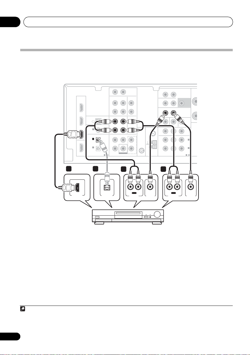
Connecting a TV and Blu-ray Disc player or DVD player
This page shows you how to connect your BD/DVD player and TV to the receiver.
This receiver
RAUX
L
IN
HDMI
2 4
VIDEO IN
RL
ANALOG AUDIO OUT
HDMI
BD/DVD
IN
TV/SAT
IN
DVR/VCR
IN
OUT
OUT
IR
IN
ASSIGNABLE
COAXIAL
COAXIAL
IN 1
IN 1
(CD)
(CD)
OPTICAL
IN 2
(AUX)
IN 1
IN 1
(CD-R/TAPE)
(CD-R/TAPE)
ASSIGNABLE ASSI
1-2
CD-R/TAPE CD
OUT
DVR/VCR TV/SAT
OUT
AUDIODIGITAL
BD/DVD MULTI CH IN
CENTERSURROUND
SUBWOOFER
IN IN
IN
TV/SAT
FRONT
BD/DVD IN
BD/DVD IN
ZONE2
UNBAL
75
LOOP
FM
Ω
AM
ANTENNA
OUT
OUT
MONITOR OUT BD/DVD IN
MONITOR OUT BD/DVD IN TV/SA
COMPONENT VIDEO
L
R
IN
IN
L
L
R
R
L
L
SIRIUS
IN
R
R
SURROUND
R
BACK
DVR/VCR
L (Single)R
PRE
SU
L R
IN
YPBP
2
HDMI IN
TV
OPTICAL
DIGITAL
AUDIO OUT
4
1
1 Connect the HDMI output on your
BD/DVD player to the HDMI BD/DVD IN input
on this receiver.
Use an HDMI cable for the connection. If an
HDMI output is not on your DVD player, use a
digital audio cable to connect the coaxial or
optional output and this unit.
Note
1 In this case, you’ll need to tell the receiver which digital input you connected the player to (see Choosing the input signal on
page 40).
2 • When you use an HDMI cable for connection in steps 1 and 2, you can enjoy the home theater in multichannel playback
without following steps 3 and 4.
• The OSD will not appear if you have connected using the HDMI output to your TV. Use component or composite connections
for system setup.
3See Using the component video jacks on page 19 if you want to use the component video outputs to connect this receiver to
your TV.
1
1
HDMI OUT
COAXIAL
DIGITAL
AUDIO OUT
BD/DVD player
RL
ANALOG AUDIO OUT
2 Connect the HDMI OUT on this receiver to
an HDMI input on your TV.
If an HDMI input is not on your TV, connect the
MONITOR OUT video jack on this receiver to a
video input on your TV.
Use a standard RCA video cable to connect to
the composite video jack.
3
2
3
14
En
VIDEO OUT

Connecting up 03
3 Connect the composite video output and
the stereo analog audio outputs
1
on your
BD/DVD player to the BD/DVD inputs on this
receiver.
Use a standard RCA video cable
2
and a stereo
RCA phono cable for the connection.
• If your BD/DVD player has multichannel
analog outputs, see Connecting the
multichannel analog outputs below
for how to connect it.
4 Connect the analog audio outputs from
your TV to the TV/SAT inputs on this receiver.
This will allow you to play the sound from the
TV’s built-in tuner. Use a stereo RCA phono
cable to do this.
• If your TV has a built-in digital decoder, you
can also connect an optical digital audio
output from your TV to the DIGITAL
OPTICAL IN 2 (AUX) input on this receiver.
Use an optical cable for the connection.
3
Connecting the multichannel analog outputs
For DVD Audio and SACD playback, your BD/DVD player may have 5.1 channel analog outputs. In this
case, you can connect them to the multichannel analog outputs to the multichannel inputs of this
receiver as shown below.
4
This receiver
HDMI
BD/DVD
IN
TV/SAT
IN
DVR/VCR
IN
OUT
(CD-R/TAPE)
COAXIAL
OPTICAL
IN 1
IN 2
(AUX)
IN 1
R AUX
L
IN
IN IN
CD-R/TAPE CD
OUT
DVR/VCR TV/SAT
OUT
IR
IN
ASSIGNABLE
(CD)
ASSIGNABLE
1-2
AUDIODIGITAL
IN
CENTERSURROUND
FRONT
FRONT
CENTERSURROUND
BD/DVD IN
SUBWOOFER
SUBWOOFER
BD/DVD MULTI CH IN
BD/DVD MULTI CH IN
L
R
IN
L
R
UNBAL
75
L
L
SIRIUS
IN
R
R
LOOP
ZONE2
OUT
OUT
MONITOR OUT BD/DVD IN TV/SAT IN
ANTENNA
FM
Ω
AM
COMPONENT VIDEO
SURROUND
L (Single)R
BACK
L R
IN
DVR/VCR VIDE
BD/DVD IN
R
PRE OUT
SUBWOOFER
YPBP
ASSIGNABLE
AUDI
PRE OU
OUT
IN 2
(TV/SAT
IN 1
(BD/DVD
1—2
English
Deutsch
Français
Italiano
Nederlands
CENTER
OUTPUT
RL
SURROUND
OUTPUT
WOOFER
OUTPUT
RL
SUB-
FRONT
OUTPUT
DVD/multi-channel decoder
VIDEO
OUTPUT
with multi-channel analog
output jacks
Note
1 This connection will allow you to make analog recordings from your BD/DVD player.
2 If your player also has a component video output, you can connect this too. See Using the component video jacks on page 19
for more on this.
3 In this case, you’ll need to tell the receiver which digital input you connected the TV to (see Choosing the input signal on page 40).
4 • The multichannel input can only be used when MULTI IN is selected (see page 40).
• You can assign COMPONENT VIDEO IN 1 or IN 2 to the multi channel input. (For more on this, see The Input Assign menu
on page 44.)
Español
15
En

Connecting up03
Connecting a satellite receiver or other digital set-top box
Satellite and cable receivers, and terrestrial digital TV tuners are all examples of so-called ‘set-top
boxes’.
This receiver
R AUX
HDMI
HDMI
BD/DVD
IN
TV/SAT
TV/SAT
IN
IN
DVR/VCR
IN
OUT
COAXIAL
IN 1
(CD)
OPTICAL
IN 2
IN 2
(AUX)
(AUX)
IN 1
(CD-R/TAPE)
IN
IR
ASSIGNABLE
ASSIGNABLE
OUT
OUT
1-2
AUDIODIGITAL
1 1 2
L
IN
IN IN
CD-R/TAPE CD
IN
TV/SAT
DVR/VCR TV/SAT
CENTERSURROUND
BD/DVD IN
SUBWOOFER
BD/DVD MULTI CH IN
FRONT
L
R
IN
IN
L
L
R
R
UNBAL
75
L
SIRIUS
IN
R
LOOP
ZONE2
OUT
OUT
MONITOR OUT BD/DVD IN TV/SAT IN
ANTENNA
FM
Ω
AM
COMPONENT VIDEO
SURROUND
L (Single)R
BACK
L R
IN
DVR/VCR VIDEO
YPBP
R
AUDIO
PRE OUT
SUBWOOFER
PRE OUT
TV/SAT IN
OUT
IN 2
(TV/SAT)
IN 1
(BD/DVD)
ASSIGNABLE
1-2
SPEAKERS A
R
SPEAKERS B
FRONT
R
HDMI OUT
OPTICAL
DIGITAL OUT
AUDIO/VIDEO OUT
VIDEOAUDIORL
STB
1 If your set-top box has an HDMI output,
connect it to an HDMI TV/SAT IN on this
reciever.
If your set-top box does not have an HDMI
output but a digital output, connect it to a
digital input on this receiver.
The example shows an optical connection to
the DIGITAL OPTICAL IN 2 (AUX) input.
Note
1 In this case, you’ll need to tell the receiver which input you connected the set-top box to (see Choosing the input signal on
page 40).
2 If you’ve already connected your TV to the TV/SAT inputs, simply choose another input. However, to receive a signal, you’ll
need to press the input select button for the input you connected the set-top box to.
3See Using the component video jacks on page 19 if your set-top box also has a component video output.
1
2 Connect a set of audio/video outputs on
the set-top box component to the TV/SAT
AUDIO and VIDEO inputs on this receiver.
Use a stereo RCA phono cable for the audio
connection and a standard RCA video cable for
the video connection.
3
16
En
2

Connecting up 03
Connecting other audio
components
The number and kind of connections depends
on the kind of component you’re connecting.
Follow the steps below to connect a CD-R, MD,
DAT, tape recorder or other audio component.
1 If your component has a digital output,
connect this to a digital input on the receiver
as shown.
The example shows an optical connection to
the DIGITAL OPTICAL IN 1 (CD-R/TAPE)
input.
2 If necessary, connect the analog audio
outputs of the component to a set of spare
audio inputs on this receiver.
You’ll need to make this connection for
components without a digital output, or if you
want to record from a digital component. Use a
stereo RCA phono cable as shown.
3 If you’re connecting a recorder, connect
the analog audio outputs to the analog audio
inputs on the recorder.
The example shows an analog connection to
the CD-R/TAPE analog output jack using a
stereo RCA phono cable.
This receiver
R AUX
L
IN
HDMI
BD/DVD
IN
1
TV/SAT
IN
DVR/VCR
IN
OUT
DIGITAL
COAXIAL
COAXIAL
IN 1
IN 1
(CD)
(CD)
OPTICAL
OPTICAL
IN 2
(AUX)
IN 1
IN 1
(CD-R/TAPE)
(CD-R/TAPE)
IN
IR
ASSIGNABLE
ASSIGNABLE
1-2
CD-R/TAPE
CD-R/TAPE CD
OUT
OUT
DVR/VCR TV/SAT
OUT
AUDIODIGITAL
BD/DVD MULTI CH IN
AUDIO
CENTERSURROUND
SUBWOOFER
IN IN
IN
IN
FRONT
BD/DVD IN
L
L
R
R
IN
L
ANTENNA
R
FM
UNBAL
75
Ω
L
SIRIUS
IN
R
AM
LOOP
Z
O
M
English
Deutsch
Français
1 23
IN
OPTICAL COAXIAL
DIGITAL OUT
RL
REC
AUDIO IN
CD-R, MD, DAT, Tape recorder, etc.
OUT
RL
PLAY
AUDIO OUT
Italiano
Nederlands
Español
Note
1 Note that you must connect digital components to analog audio jacks if you want to record to/from digital components (like
an MD) to/from analog components.
17
En
Connecting up03
Connecting an HDD/DVD recorder, VCR and other video sources
This receiver has audio/video inputs and outputs suitable for connecting analog or digital video
recorders, including VCRs and HDD/DVD recorders.
This receiver
R AUX
HDMI
HDMI
BD/DVD
IN
TV/SAT
IN
DVR/VCR
IN
OUT
DIGITAL
COAXIAL
IN 1
(CD)
OPTICAL
OPTICAL
IN 2
IN 2
(AUX)
(AUX)
IN 1
(CD-R/TAPE)
IN
IR
ASSIGNABLE
ASSIGNABLE
1—2
CD-R/TAPE CD
OUT
DVR/VCR
DVR/VCR TV/SAT
OUT
OUT
AUDIODIGITAL
BD/DVD MULTI CH IN
IN
CENTERSURROUND
SUBWOOFER
L
IN IN
IN
IN
FRONT
BD/DVD IN
L
R
IN
L
L
R
R
FM
UNBAL
75
L
SIRIUS
IN
R
LOOP
ZONE2
OUT
OUT
OUT
MONITOR OUT BD/DVD IN TV/SAT IN
ANTENNA
Ω
AM
COMPONENT VIDEO
SURROUND
L (Single)R
BACK
L R
IN
IN
DVR/VCR VIDEO
DVR/VCR VIDEO
YPBP
R
AUDIO
PRE OUT
SUBWOOFER
PRE OUT
OUT
(TV/SAT)
(BD/DVD)
ASSIGNABLE
SPEAK
R
SPEA
IN 2
IN 1
1-2
1
HDMI OUT
1
OPTICAL
DIGITAL OUT
3 2
IN
RL
REC
VIDEO IN
AUDIO IN
OUT
RL
PLAY
AUDIO OUT
VIDEO OUT
DVR, VCR, LD player, etc.
1 If your video component has an HDMI
output, connect it to an HDMI DVR/VCR IN
on this receiver.
If your video component does not have an
HDMI audio output but a digital audio output,
connect it to a digital input on this receiver.
The example shows a recorder connected to
the DIGITAL OPTICAL IN 2 (AUX) input.
1
2 Connect a set of audio/video outputs on
the recorder to the DVR/VCR AUDIO and
VIDEO inputs on this receiver.
Use a stereo RCA phono cable for the audio
connection and a standard RCA video cable for
the video connection.
2
3 Connect a set of audio/video inputs on
the recorder to the DVR/VCR AUDIO and
VIDEO outputs on this receiver.
Use a stereo RCA phono cable for the audio
connection and a standard RCA video cable for
the video connection.
Note
1 In this case, you’ll need to tell the receiver which digital input you connected the component to (see Choosing the input signal
on page 40).
2 If your video component also has a component video output, you can connect this too. See Using the component video jacks
on page 19 for more on this.
18
En

Connecting up 03
Using the component video jacks
Component video should deliver superior picture quality when compared to composite video. A
further advantage (if your source and TV are both compatible) is progressive-scan video, which
delivers a very stable, flicker-free picture. See the manuals that came with your TV and source
component to check whether they are compatible with progressive-scan video.
This receiver
R AUX
HDMI
BD/DVD
IN
2
P
R YPB
COMPONENT VIDEO IN
TV/SAT
IN
DVR/VCR
IN
OUT
COAXIAL
IN 1
(CD)
OPTICAL
IN 2
(AUX)
IN 1
(CD-R/TAPE)
IN
1
TV
P
R YPB
COMPONENT VIDEO OUT
Important
• If you connect any source component to
the receiver using a component video
input, you must also have your TV
connected to this receiver’s COMPONENT
VIDEO OUT jacks.
1 Connect the component video outputs of
your source to a set of component video
inputs on this receiver.
Use a three-way component video cable for the
connection.
L
IN
IN IN
CD-R/TAPE CD
IR
ASSIGNABLE
ASSIGNABLE
1-2
OUT
DVR/VCR TV/SAT
OUT
AUDIODIGITAL
BD/DVD MULTI CH IN
CENTERSURROUND
SUBWOOFER
IN
FRONT
BD/DVD IN
L
R
IN
L
R
FM
UNBAL
75
L
SIRIUS
IN
R
LOOP
BD/DVD player
2 If necessary, assign the component video
inputs to the input source you’ve connected.
This only needs to be done if you didn’t
connect according to the following defaults:
• COMPONENT VIDEO IN 1 – BD/DVD
• COMPONENT VIDEO IN 2 – TV/SAT
See The Input Assign menu on page 44 for
more on this.
3 Connect the COMPONENT VIDEO OUT
jacks on this receiver to the component video
inputs on your TV or monitor.
Use a three-way component video cable.
ZONE2
OUT
OUT
MONITOR OUT BD/DVD IN TV/SAT IN
ANTENNA
Ω
AM
COMPONENT VIDEO
COMPONENT VIDEO
SURROUND
L (Single)R
BACK
L R
IN
DVR/VCR VIDEO
YPBP
YPBP
R
R
AUDIO
PRE OUT
SUBWOOFER
PRE OUT
OUT
OUT
IN 2
(TV/SAT)
IN 1
IN 1
(BD/DVD)
(BD/DVD)
ASSIGNABLE
ASSIGNABLE
1—2
1-2
SP
S
English
Deutsch
Français
Italiano
Nederlands
Español
19
En

Connecting up03
Connecting to the front panel
video terminal
Front video connections are accessed via the
front panel using the INPUT SELECTOR or
VIDEO button on the remote control. There are
standard audio/video jacks. Hook them up the
same way you made the rear panel connections.
•Push down on the PUSH OPEN tab to
access the front video connections.
VIDEO INPUT
USB
This receiver
MULTI-ZONE
SPEAKERS
CONTROL
iPod
USB
iPod
ON/OFF
VIDEO INPUT
AUDIO/VIDEO OUTPUT
RLAUDIOVIDEO
MASTER
VOLUME
RLAUDIOVIDEO
MCACC
SETUP MIC
Video camera
(etc.)
LVIDEO
R
Connecting antennas
Connect the AM loop antenna and the FM wire
antenna as shown below. To improve reception
and sound quality, connect external antennas
(see Using external antennas on page 21).
fig. a fig. b
2
3
1
LOOP
ANTENNA
AM
4
1 Push open the tabs, then insert one wire
fully into each terminal, then release the tabs
to secure the AM antenna wires.
2 Fix the AM loop antenna to the attached
stand.
To fix the stand to the antenna, bend in the
direction indicated by the arrow (fig. a) then
clip the loop onto the stand (fig. b).
3 Place the AM antenna on a flat surface
and in a direction giving the best reception.
4 Connect the FM wire antenna in the same
way as the AM loop antenna.
For best results, extend the FM antenna fully
and fix to a wall or door frame. Don’t drape
loosely or leave coiled up.
20
En

Connecting up 03
Using external antennas
To improve FM reception
Use an F connector (not supplied) to connect
an external FM antenna.
ANTENNA
FM
UNBAL
75
Ω
AM
LOOP
To improve AM reception
Connect a 5 m to 6 m (15 ft. to 18 ft.) length of
vinyl-coated wire to the AM antenna terminal
without disconnecting the supplied AM loop
antenna.
For the best possible reception, suspend
horizontally outdoors.
Outdoor
antenna
F connecto
ANTENNA
FM
UNBAL
75
Ω
AM
LOOP
English
Deutsch
Français
Italiano
Nederlands
Español
Indoor antenna
(vinyl-coated wire)
5 m to 6 m
(15 ft. to 18 ft.)
21
En

Connecting up03
Connecting the speakers
A complete setup of six speakers (including the
subwoofer) is shown here but everyone’s home
setup will vary. Simply connect the speakers
you have in the manner shown below. The
receiver will work with just two stereo speakers
(the front speakers in the diagram) but using at
least three speakers is recommended, and a
complete setup is best for surround sound. If
you’re not using a subwoofer, change the front
speaker setting (see Speaker Setting on
page 42) to LARGE.
Make sure you connect the speaker on the
right to the right terminal and the speaker on
the left to the left terminal.
SW
Powered subwoofer
Front speakers
R
L
You can use the speakers connected to the B
speaker terminals to listen to stereo playback
in another room. Make sure to review Placing
the speakers on page 24 when placing the
speakers in another room. See Switching the
speaker system on page 25 for the listening
options with this setup.
You can use speakers with a normal
impedance between 6 Ω and 16 Ω.
However, note that only the front speakers are
set to a value between 12 Ω and 16 Ω if you
select SPAB in Switching the speaker system
on page 25.
Be sure to complete all connections before
connecting this unit to the AC power source.
Center speaker
C
Surround speakers
SL SR
22
En
SURROUND
BACK
IN
L
R
IN
L
R
L
SIRIUS
IN
R
IN
UNBAL
75
LOOP
FM
Ω
AM
ANTENNA
ZONE2
OUT
DVR/VCR VIDEO
OUT
MONITOR OUT BD/DVD IN TV/SAT IN
R
COMPONENT VIDEO
L (Single)R
L R
IN
PRE OUT
SUBWOOFER
SUBWOOFER
PRE OUT
PRE OUT
YPBP
(TV/SAT)
(BD/DVD)
ASSIGNABLE
SPEAKERS A
SPEAKERS A
AUDIO
RL
RL
SPEAKERS B
SPEAKERS B
OUT
IN 2
IN 1
1-2
FRONT
FRONT
RL
RL
SURROUND CENTER
SURROUND CENTER
R L
R L
Class 2 Wiring
Class 2 Wiring
Speaker system B
LR

Connecting up 03
Bare wire connections
A-Speaker terminals:
1 Twist exposed wire strands together.
2 Loosen terminal and insert exposed wire.
3 Tighten terminal.
123
10 mm
(3/8 in.)
B-Speaker terminals:
1 Twist exposed wire strands together.
2 Push open the tabs and insert exposed
wire.
3 Release the tabs.
12
3
10 mm
(3/8 in.)
Caution
• These speaker terminals carry
HAZARDOUS LIVE voltage. To prevent
the risk of electric shock when connecting
or disconnecting the speaker cables,
disconnect the power cord before touching
any uninsulated parts.
• Make sure that all the bare speaker wire is
twisted together and inserted fully into the
speaker terminal. If any of the bare speaker
wire touches the back panel it may cause
the power to cut off as a safety measure.
Use the PRE OUT outputs to connect
the surround back speakers
Connect the PRE OUT outputs of the unit and
additional amplifier to add a surround back
speaker.
Surround back
channel amplifier
ANALOG
INPUT
LR
SURROUND
L (Single)R
BACK
ZONE2
OUT
L R
IN
DVR/VCR VIDEO
OUT
MONITOR OUT BD/DVD IN TV/SAT IN
R
ANTENNA
FM
UNBAL
75
Ω
AM
LOOP
COMPONENT VIDEO
• You can use the additional amplifier on the
surround back channel pre-outs for a
single speaker as well. In this case plug
the amplifier into the left (L (Single))
terminal only.
Surround Back speakers
SPEAKERS A
AUDIO
SUBWOOFER
PRE OUT
OUT
IN 2
(TV/SAT)
IN 1
(BD/DVD)
1-2
FRONT
RL
SPEAKERS B
PRE OUT
YPBP
ASSIGNABLE
Class 2 Wiring
RL
SBL SBR
SURR
R
English
Deutsch
Français
Italiano
Nederlands
Español
23
En

Connecting up03
Placing the speakers
To achieve the best possible surround sound,
install your speakers as shown below.
5.1 channel surround system:
Front left
Surround
left
Center
Subwoofer
120°
6.1 channel surround system:
Front left
Surround
left
Center
Subwoofer
120°
Surround Back
7.1 channel surround system:
Front left Front right
Surround
left
Surround back
Center
Subwoofer
90°
left
60°
Front right
120°
1
Front right
120°
1
90°
Surround back
right
Surround
right
Surround
right
Surround
right
Where you put your speakers in the room has a
big effect on the quality of the sound. The
following guidelines should help you to get the
best sound from your system.
• The subwoofer can be placed on the floor.
Ideally, the other speakers should be at
about ear-level when you’re listening to
them. Putting the speakers on the floor
(except the subwoofer), or mounting them
very high on a wall is not recommended.
• For the best stereo effect, place the front
speakers 2 m to 3 m (6 ft. to 9 ft.) apart, at
equal distance from the TV.
• When placing speakers near the TV, we
recommend using magnetically shielded
speakers to prevent possible interference,
such as discoloration of the picture when
the TV is switched on. If you do not have
magnetically shielded speakers and notice
discoloration of the TV picture, move the
speakers farther away from the TV.
• If you’re using a center speaker, place the
front speakers at a wider angle. If not, place
them at a narrower angle.
• Place the center speaker above or below
the TV so that the sound of the center
channel is localized at the TV screen. Also,
make sure the center speaker does not
cross the line formed by the leading edge
of the front left and right speakers.
• It is best to angle the speakers towards the
listening position. The angle depends on
the size of the room. Use less of an angle
for bigger rooms.
• Surround and surround back speakers
should be positioned 60 cm to 90 cm (2 ft.
to 3 ft.) higher than your ears and titled
slight downward. Make sure the speakers
don’t face each other. For DVD-Audio, the
speakers should be more directly behind
the listener than for home theater playback.
Note
1 • This layout is available only when the additional amplifier is connected to the unit and the surround back speakers are
connected to the amplifier. For details, see Use the PRE OUT outputs to connect the surround back speakers on page 23.
• When the Surround back channel processing is set to SB CH ON (see page 37) in this layout, sound is output from the
surround back speakers even with the use of 5.1ch input signal.
24
En

Connecting up 03
• If the surround speakers cannot be set
directly to the side of the listening position
with a 7.1-channel system, the surround
effect can be enhanced by turning off the
UP Mix function (see Setting the Up Mix
function on page 37).
• Try not to place the surround speakers
farther away from the listening position
than the front and center speakers. Doing
so can weaken the surround sound effect.
Caution
• Make sure that all speakers are securely
installed. This not only improves sound
quality, but also reduces the risk of
damage or injury resulting from speakers
being knocked over or falling in the event of
external shocks such as earthquakes.
Switching the speaker system
Three speaker system settings are possible
using the SPEAKERS button.
• Use the SPEAKERS button on the front
panel to select a speaker system setting.
CONTROL
MULTI-ZONE
ON/OFF
SPEAKERS
SPEAKERS
1
• SPAB – Sound is output from speaker
system A, the two speakers in speaker
system B, and the subwoofer.
Multichannel sources are downmixed only
when the STEREO or A.L.C mode is
selected for stereo output from speaker
2
systems A and B.
• SP – No sound is output from the
speakers but from the headphone jack.
English
Deutsch
Français
Italiano
Nederlands
Press repeatedly to choose a speaker system
option:
• SPA – Sound is output from the speakers
connected to the A speaker terminals and
SURROUND BACK PRE OUT
(multichannel playback is possible).
• SPB – Sound is output from the two
speakers connected to speaker system B
(only stereo playback is possible).
Note
1 The subwoofer output depends on the settings you made in Speaker Setting on page 42. However, if SPB is selected above,
no sound is heard from the subwoofer (the LFE channel is not downmixed).
2 You can use speakers with a normal impedance between 6 Ω and 16 Ω. However, be aware that only the front speakers are set
to a value between 12 Ω and 16 Ω when you select SPAB.
Español
25
En

Controls and displays04
Chapter 4:
Controls and displays
Front panel
1 23 64 5
STANDBY/ON
INPUT
SELECTOR
1
STANDBY/ON
2
INPUT SELECTOR
Selects an input source.
3 Tuner control buttons
BAND
Switches between AM, FM ST (stereo) and
FM MONO radio bands (page 48).
TUNE +/–
Used to find radio frequencies (page 48)
and SIRIUS Radio channels (page 63).
TUNER EDIT
Use with TUNE +/–, PRESET +/– and
ENTER to memorize and name stations for
recall (page 48, 49). Used to preset the
channel in SIRIUS Radio (page 63).
PRESET +/–
Use to select preset radio stations
(page 49) and to select SIRIUS Radio
channels (page 63).
4 Character display
See Display on page 28.
PHASE
CONTROL
–
STEREO/
+
TUNE
ADVANCED
SURROUND
STANDARD
SURROUND
A.L.C.
PRESET
TUNER EDIT ENTER
SPEAKERS
TUNE
BAND
AUTO SURROUND/
STREAM DIRECT
PHONES
7 8 10 13129 11
5
MCACC
dial
Lights when Acoustic Calibration EQ (page 36) is
on (Acoustic Calibration EQ is automatically set
to on after the Auto MCACC Setup (page 9)).
6
MASTER VOLUME
PHONES
7
Use to connect headphones (page 40).
8 Listening mode buttons
AUTO SURROUND/STREAM DIRECT
Switches between Auto surround mode
(Auto playback on page 33) and Stream
Direct playback. Stream Direct playback
bypasses the tone controls for the most
accurate reproduction of a source
(page 36).
STEREO/A.L.C.
Switches between stereo playback, Auto
level control stereo mode (page 35) and
Front Stage Surround Advance modes
(page 35).
–
CONTROL
USB
+
PRESET
MULTI-ZONE
ON/OFF
VIDEO INPUT
iPod
indicator
jack
RLAUDIOVIDEO
AUDIO/VIDEO MULTI- CHANNEL RECEIVER VSX
MCACC
SETUP MIC
dial
–
MASTER
VOLUME
819H
26
En
Controls and displays 04
ADVANCED SURROUND
Switches between the various surround
modes (page 34).
STANDARD SURROUND
Press for Standard decoding and to switch
between the various 2 Pro Logic II, 2 Pro
Logic IIx and NEO:6 options (page 33).
9SPEAKERS
Use to change the speaker system (page 25).
10 MULTI ZONE controls
If you’ve made MULTI-ZONE connections (see
MULTI-ZONE listening on page 46) use these
controls to control the sub zone from the main
zone (see Using the MULTI-ZONE controls on
page 47).
11
iPod
/USB terminal
Use to connect your Apple iPod or USB mass
storage device as an audio source (page 58
and page 60).
12
AUDIO/VIDEO
input
See Connecting to the front panel video terminal
on page 20.
13
MCACC SETUP MIC
jack
Use to connect a microphone when
performing Auto MCACC setup.
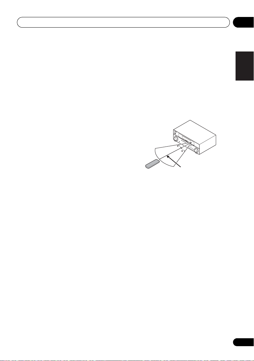
Operating range of remote control
The remote control may not work properly if:
• There are obstacles between the remote
control and the receiver’s remote sensor.
• Direct sunlight or fluorescent light is
shining onto the remote sensor.
• The receiver is located near a device that is
emitting infrared rays.
• The receiver is operated simultaneously
with another infrared remote control unit.
STANDBY/ON
INPUT
SELECTOR
PHASE
CONTROL
BAND
TUNE
–
AUTO SURROUND/
STREAM DIRECT
TUNE
+
STEREO/
A.L.C.
PHONES
ADVANCED
TUNER
SURROUND
EDIT ENTER
STANDARD
AUDIO
SURROUND
/
VIDEO MULTI-
PRESET
–
CHANNEL
SPEAKERS
RECEIVER
PRESET
+
VSX
CONTROL
MULTI-ZONE
–
519V
ON/OFF
30
30
MASTER
VOLUME
PORTABLE
7 m (23 ft.)
English
Deutsch
Français
Italiano
Nederlands
Español
27
En

Controls and displays04
Display
1 2 3 4 5 6 7 8
9
10
1PHASE
Lights when the Phase Control is switched on
(page 11).
2AUTO
Lights when the Auto Surround feature is
switched on (see Auto playback on page 33).
3ST
Lights when a stereo FM broadcast is being
received in auto stereo mode.
4TUNE
Lights when a normal broadcast channel or
SIRIUS channel is being received.
5ZONE
Lights when the MULTI-ZONE feature is active
(page 46).
6 Speaker indicators
Lights to indicate the current speaker system,
A and/or B (page 25).
7 Sleep timer indicator
Lights when the receiver is in sleep mode
(page 32).
8 Tuner/SIRIUS preset indicators
PRESET
Shows when a preset radio station is
registered or called.
MEM
Blinks when a radio station is registered.
11 12 13 14 14 1615
9 PRESET Information or Input signal
indicator
Shows the preset number of the tuner or the
input signal type, etc.
10 Character display
Displays various system infomation.
11 DTS indicators
DTS
Lights when a source with DTS encoded
audio signals is detected.
HD
Lights when a source with DTS-EXPRESS
or DTS-HD encoded audio signals is
detected.
ES
Lights when a source with DTS-ES
encoded audio signals is detected.
96/24
Lights when a source with DTS 96/24
encoded audio signals is detected.
NEO:6
When one of the NEO:6 modes of the
receiver is on, this lights to indicate
NEO:6 processing (page 33).
12 Dolby Digital indicators
2
Lights when a Dolby Digital encoded signal
is detected.
28
En

Controls and displays 04
HD+
Lights when a source with Dolby Digital
Plus encoded audio signals is detected.
HD
Lights when a source with Dolby TrueHD
encoded audio signals is detected.
EX
Lights when a source with Dolby Digital EX
encoded audio signals is detected.
2PLllx
Lights to indicate 2 Pro Logic II / 2 Pro
Logic IIx decoding (see Listening in
surround sound on page 33 for more on
this).
13 ADV.S.
Lights when one of the Advanced Surround
modes has been selected (see Using the
Advanced surround effects on page 34 for more
on this).
14 SIGNAL SELECT indicators
DIGITAL
Lights when a digital audio signal is
selected.
Blinks when a digital audio signal is not
selected.
HDMI
Lights when an HDMI signal is selected.
Blinks when an HDMI signal is not
selected.
15 UP MIX indicator
Lights when the UP MIX Setting is set to ON
(see page 37). Also, lights when DIMMER is set
to off.
16 DIR.
Lights when the DIRECT or PURE DIRECT
mode is switched on (page 36).
English
Deutsch
Français
Italiano
Nederlands
Español
29
En

Controls and displays04
Remote control
1
RECEIVER
RECEIVER
BD TV
CD CD-R
VIDEO MULTI IN
iPod USB
AUTO/
DIRECT
AUDIO
PARAMETER
TOP
MENU
T
E
S
E
R
P
HOME
MENU
SETUP
iPod
CTRL
CATEGORY
HDD
1
S.RETRIEVER
4
SB CH
7
DIMMER
+
D.ACCESS
BASS
10
INPUT SELECT
ZONE 2
ON/OFF
SIRIUS
STEREO/
A.L.C.
U
T
ENTER
T
U
DVD
EQ
PHASE
SPEAKERS
RECEIVER
212
3
4
5
6
7
8
9
10
11
N
E
E
N
2
5
8
0
TV CONTROL
INPUT
DVR
TUNER
AUX
SIGNAL SEL
BD MENU
STANDARD
TUNER EDIT
TOOLS
P
R
E
S
E
T
RETURN
ANT
VCR
3
CH SELECT
6
9
ENTER
SOURCE
ADV SURR
MENU
BAND
TRE
DISPLAY
MIDNIGHT
CH
VOL
MASTER
VOLUME
MUTE
SLEEP
CH
CH
SHIFT
13
14
15
16
17
1 INPUT SELECT
Use to select the input source.
2
RECEIVER
Switches the receiver between standby and on.
3 RECEIVER
Switches the remote to control the receiver
(used to select the white commands above the
number buttons (S.RETRIEVER, etc)). Also use
this button to set up surround sound (page 41)
or Audio parameters (page 38).
4 ZONE 2 ON/OFF
Switches zone 2 of the multi-zone function
between on and off.
5
MULTI CONTROL
buttons
Press to select control of other components (see
Controlling the rest of your system on page 51
6
SIGNAL SEL
Use to select an input signal (page 40).
Press BD first to access:
BD MENU
Displays the disc menu of Blu-ray Discs.
7 Listening mode buttons
AUTO/DIRECT
Switches between Auto surround mode
(Auto playback on page 33) and Stream
Direct playback. Stream Direct playback
bypasses the tone controls for the most
accurate reproduction of a source
(page 36).
STEREO/A.L.C.
Switches between stereo playback, Auto
level control stereo mode (page 35) and
Front Stage Surround Advance modes
(page 35).
STANDARD
Press for Standard decoding and to switch
between 2 Pro Logic II options (page 33).
ADV SURR
Switches between the various surround
modes (page 34).
).
30
En
Loading…
- Topics
- manualsbase, manuals,
- Collection
- manuals_pioneer; manuals; additional_collections
- Language
- English
- Item Size
- 179.9M
- Addeddate
- 2020-08-16 08:19:21
- Identifier
- manualsbase-id-434192
- Identifier-ark
- ark:/13960/t8dg5x952
- Ocr
- ABBYY FineReader 11.0 (Extended OCR)
- Ppi
- 600
- Scanner
- Internet Archive Python library 1.9.4
plus-circle Add Review
plus-circle Add Review
comment
Reviews
There are no reviews yet. Be the first one to
write a review.
181
Views
DOWNLOAD OPTIONS
download 1 file
ABBYY GZ download
Temporarily Unavailable
DAISY
For users with print-disabilities
Temporarily Unavailable
EPUB
download 1 file
FULL TEXT download
download 1 file
ITEM TILE download
download 1 file
PAGE NUMBERS JSON download
download 1 file
PDF download
download 1 file
SINGLE PAGE PROCESSED JP2 ZIP download
download 1 file
TORRENT download
download 12 Files
download 6 Original
SHOW ALL
IN COLLECTIONS
Manuals: Pioneer
The Manual Library
Additional Collections
Uploaded by
chris85
on

VSX-819H
-S/-K
VSX-819H_RLF.book 1 ページ 2009年1月20日 火曜日 午前10時36分
Pioneer VSX-819H-K
Register your product at:
www.pioneerelectronics.com (US)
www.pioneerelectronics.ca (Canada)
• Protect your new investmentThe details of your purchase will be on file for reference in the event of aninsurance claim such as loss or theft.• Improve product developmentYour input helps us continue to design products that meet your needs.• Receive a free Pioneer newsletterRegistered customers can opt in to receive a monthly newsletter.• Receive free tips, updates and service bulletins onyour new product
AUDIO/VIDEO MULTI-CHANNEL RECEIVER
RECEPTEUR AUDIOVISUEL A
VOIES MULTIPLES
RECEPTOR MULTICANAL DE AUDIO/VÍDEO
Operating Instructions
Mode d’emploi
Manual de instrucciones
VSX-819H_KU.book Page 1 Thursday, December 25, 2008 8:36 AM
Manual
View the manual for the Pioneer VSX-819H-K here, for free. This user manual comes under the category receivers and has been rated by 14 people with an average of a 8.4. This manual is available in the following languages: English. Do you have a question about the Pioneer VSX-819H-K?
Ask your question here
Index
- Checking what’s in the box . . . . . . . . . . . . . . . 6
- Loading the batteries . . . . . . . . . . . . . . . . . . . 6
- Installing the receiver . . . . . . . . . . . . . . . . . . . 6
- Ventilation . . . . . . . . . . . . . . . . . . . . . . . . . . 6
- 02 5 minute guide
- Introduction to home theater . . . . . . . . . . . . . 8
- Listening to Surround Sound . . . . . . . . . . . . . 8
- Automatically setting up for surroundsound (MCACC) . . . . . . . . . . . . . . . . . . . . . . . 9
- Other problems when using theAuto MCACC Setup . . . . . . . . . . . . . . . . . . 11
- Better sound using Phase Control . . . . . . . . 11
- Making cable connections . . . . . . . . . . . . . . 12
- Switching the speaker system . . . . . . . . . . 25
- Front panel . . . . . . . . . . . . . . . . . . . . . . . . . . 26
- Display . . . . . . . . . . . . . . . . . . . . . . . . . . . . . 28
- Remote control . . . . . . . . . . . . . . . . . . . . . . . 30
- Auto playback . . . . . . . . . . . . . . . . . . . . . . . . 33
- Listening in surround sound . . . . . . . . . . . . . 33
- Listening in stereo . . . . . . . . . . . . . . . . . . . . . 35
- Using Front Stage Surround Advance . . . . . . 35
- Using Stream Direct . . . . . . . . . . . . . . . . . . . 36
- Using the Sound Retriever. . . . . . . . . . . . . . . 36
- Listening with Acoustic Calibration EQ . . . . . 36
- Using surround back channel processing . . . 37
- Setting the Up Mix function. . . . . . . . . . . . . . 37
- Setting the Audio options . . . . . . . . . . . . . . . 38
- Playing other sources . . . . . . . . . . . . . . . . . . 40
- Choosing the input signal . . . . . . . . . . . . . . . 40
- Selecting the multichannel analog inputs. . . . 40
- Using the headphone . . . . . . . . . . . . . . . . . . 40
- Using the System Setup menu . . . . . . . . . . . 41
- Manual speaker setup . . . . . . . . . . . . . . . . . . 41
- The Input Assign menu . . . . . . . . . . . . . . . . . 44
- MULTI-ZONE listening . . . . . . . . . . . . . . . . . . 46
- Using the MULTI-ZONE controls . . . . . . . . . 47
- Listening to the radio. . . . . . . . . . . . . . . . . . . 48
- Saving station presets . . . . . . . . . . . . . . . . . . 48
- Listening to station presets . . . . . . . . . . . . . 49
- Naming preset stations. . . . . . . . . . . . . . . . 49
- Making an audio or a video recording . . . . . . 50
- Setting the remote to control othercomponents . . . . . . . . . . . . . . . . . . . . . . . . . 51
- Selecting preset codes directly . . . . . . . . . . . 51
- Clearing all the remote control settings. . . . . 51
- Preset Code List . . . . . . . . . . . . . . . . . . . . . . 55
- Connecting an iPod. . . . . . . . . . . . . . . . . . . . 58
- Connecting your SiriusConnect TMTuner . . . . . . . . . . . . . . . . . . . . . . . . . . . . . 63
- Listening to SIRIUS Radio. . . . . . . . . . . . . . 63
- Saving channel presets. . . . . . . . . . . . . . . . 64
- Using the SIRIUS Menu . . . . . . . . . . . . . . . 64
- Connecting an IR receiver . . . . . . . . . . . . . . . 64
- Troubleshooting . . . . . . . . . . . . . . . . . . . . . . 65
- Vérification des accessoires livrés avecl’appareil . . . . . . . . . . . . . . . . . . . . . . . . . . . . . 6
- Chargement des piles . . . . . . . . . . . . . . . . . . . 6
- Installation du récepteur . . . . . . . . . . . . . . . . . 6
- Ventilation . . . . . . . . . . . . . . . . . . . . . . . . . . 6
- Présentation de l’appareil de cinémaà domicile . . . . . . . . . . . . . . . . . . . . . . . . . . . . 8
- Écoute en son surround . . . . . . . . . . . . . . . . . 8
- Configuration automatique du sonsurround (MCACC) . . . . . . . . . . . . . . . . . . . . . 9
- Un son meilleur grâce à la fonctionPhase Control . . . . . . . . . . . . . . . . . . . . . . . . 11
- Raccordements des câbles . . . . . . . . . . . . . . 12
- À propos du raccordement des sorties vidéo. . . 13
- Raccordement d’un téléviseur et d’unlecteur de disques Blu-ray (BD) ou d’unlecteur de DVD . . . . . . . . . . . . . . . . . . . . . . . 14
- Permutation du système d’enceintes . . . . . 25
- Panneau frontal. . . . . . . . . . . . . . . . . . . . . . . 26
- Affichage. . . . . . . . . . . . . . . . . . . . . . . . . . . . 28
- Télécommande . . . . . . . . . . . . . . . . . . . . . . . 30
- Lecture en mode Auto . . . . . . . . . . . . . . . . . . 33
- Écoute d’une source en son surround. . . . . . 33
- Utilisation du casque d’écoute . . . . . . . . . . . 40
- Utilisation du menu de configurationdu système . . . . . . . . . . . . . . . . . . . . . . . . . . 41
- Réglage manuel des enceintes . . . . . . . . . . . 41
- Réglage des enceintes . . . . . . . . . . . . . . . . 42
- Réseau de recouvrement . . . . . . . . . . . . . . 43
- Niveau des canaux . . . . . . . . . . . . . . . . . . . 43
- Distance des enceintes. . . . . . . . . . . . . . . . 44
- Menu d’affectation d’entrée . . . . . . . . . . . . . 44
- Écoute MULTI-ZONE . . . . . . . . . . . . . . . . . . . 46
- Pour écouter la radio . . . . . . . . . . . . . . . . . . . 48
- Pour écouter les stations préréglées. . . . . . 49
- Attribution de noms aux stationspréréglées. . . . . . . . . . . . . . . . . . . . . . . . . . 49
- Faire un enregistrement audio ou vidéo . . . . 50
- Configurer la télécommande pourcommander d’autres composants. . . . . . . . . 51
- Liste des codes de préréglage . . . . . . . . . . . . 55
- Connexion d’un iPod . . . . . . . . . . . . . . . . . . . 58
- TM . . . . . . . . . . . . . . . . . . . . . 63
- Écoute de SIRIUS Radio . . . . . . . . . . . . . . . 63
- Mémorisation des stationsprésélectionnées. . . . . . . . . . . . . . . . . . . . . 64
- Utilisation du Menu SIRIUS . . . . . . . . . . . . 64
- Raccordement d’un récepteur IR . . . . . . . . . 64
- Guide de dépannage . . . . . . . . . . . . . . . . . . . 65
- HDMI . . . . . . . . . . . . . . . . . . . . . . . . . . . . . 67
- Information importante concernantla connexion HDMI . . . . . . . . . . . . . . . . . . . 67
- iPod messages . . . . . . . . . . . . . . . . . . . . . . 68
- Messages USB . . . . . . . . . . . . . . . . . . . . . . 68
- Messages radio SIRIUS. . . . . . . . . . . . . . . . 68
- Réinitialisation de l’appareil principal . . . . . . 69
- Spécifications . . . . . . . . . . . . . . . . . . . . . . . . 69
- Précautions d’usage pour le cordond’alimentation . . . . . . . . . . . . . . . . . . . . . . . . 70
- Nettoyage de l’appareil . . . . . . . . . . . . . . . . . 70
- Comprobación del contenido de la caja . . . . . 6
- Instalación de las pilas . . . . . . . . . . . . . . . . . . 6
- Instalación del receptor . . . . . . . . . . . . . . . . . 6
- Ventilación . . . . . . . . . . . . . . . . . . . . . . . . . . 6
- Introducción al cine en casa . . . . . . . . . . . . . . 8
- Reproducción con sonido envolvente . . . . . . . 8
- Configuración automática para sonidoenvolvente (MCACC) . . . . . . . . . . . . . . . . . . . . 9
- Sonido mejorado con Phase Control. . . . . . . 11
- Conexiones de los cables . . . . . . . . . . . . . . . 12
- Acerca de la conexión de salidas de vídeo . . . . 13
- Cambio del sistema de altavoces . . . . . . . . 25
- Panel frontal . . . . . . . . . . . . . . . . . . . . . . . . . 26
- Alcance operativo del mando a distancia. . . . 27
- Mando a distancia. . . . . . . . . . . . . . . . . . . . . 30
- Reproducción automática . . . . . . . . . . . . . . . 33
- Reproducción con sonido envolvente . . . . . . 33
- Uso de los efectos de sonido envolventeavanzados. . . . . . . . . . . . . . . . . . . . . . . . . . 34
- Reproducción estéreo . . . . . . . . . . . . . . . . . . 35
- Uso de Front Stage Surround Advance . . . . . 35
- Uso de Stream Direct . . . . . . . . . . . . . . . . . . 36
- Uso de Sound Retriever. . . . . . . . . . . . . . . . . 36
- Reproducción con el ecualizador decalibración acústica . . . . . . . . . . . . . . . . . . . 36
- Uso del procesamiento del canalenvolvente trasero . . . . . . . . . . . . . . . . . . . . . 37
- Ajuste de la función Up Mix . . . . . . . . . . . . . 37
- Ajuste de las opciones de Audio . . . . . . . . . . 38
- Reproducción de otras fuentes . . . . . . . . . . . 40
- Selección de la señal de entrada . . . . . . . . . . 40
- Selección de las entradas analógicasmulticanal . . . . . . . . . . . . . . . . . . . . . . . . . . . 40
- Uso de los auriculares. . . . . . . . . . . . . . . . . . 40
- Uso del menú System Setup . . . . . . . . . . . . . 41
- Configuración manual de los altavoces . . . . . 41
- El menú Input Assign . . . . . . . . . . . . . . . . . . 44
- Escucha en MULTIZONA. . . . . . . . . . . . . . . . 46
- Uso de los controles MULTIZONA. . . . . . . . 47
- Recepción de radio . . . . . . . . . . . . . . . . . . . . 48
- Cómo sintonizar emisoras memorizadas . . . . 49
- Asignación de nombres a las estaciones . . . . 49
- Cómo hacer una grabación de audioo vídeo. . . . . . . . . . . . . . . . . . . . . . . . . . . . . . 50
- Uso del mando a distancia para controlarotros componentes . . . . . . . . . . . . . . . . . . . . 51
- Controles para otros componentes . . . . . . . . 53
- Lista de códigos de preajuste . . . . . . . . . . . . 55
- Conexión de un iPod . . . . . . . . . . . . . . . . . . . 58
- TM . . . . . . . . . . . . . . . . . . . . . 63
- Escucha de SIRIUS Radio. . . . . . . . . . . . . . 63
- Conexión de un receptor de infrarrojos . . . . . 64
- Solución de problemas . . . . . . . . . . . . . . . . . 65
- Restablecimiento de los ajustes pordefecto del equipo . . . . . . . . . . . . . . . . . . . . . 69
- Especificaciones . . . . . . . . . . . . . . . . . . . . . . 69
- Cable de alimentación. . . . . . . . . . . . . . . . . . 70
- Limpieza del equipo. . . . . . . . . . . . . . . . . . . . 70
Product Images (7)

Pioneer VSX-819H-K specifications
Below you will find the product specifications and the manual specifications of the Pioneer VSX-819H-K.
The pioneer vsx-819h-k receiver is a wired 5.1 channel audio output device that delivers a robust audio power of 130 W, making it ideal for home theaters. With a signal-to-noise ratio of 98 dB and impedance of 6Ω, it promises a clear and crisp sound quality. Additionally, its compact design of 420 x 347.7 x 158 mm makes it easy to store the device without taking up a lot of space.
The Pioneer VSX-819H-K features a 3.5 mm headphone jack for private listening, making it convenient for late-night audio sessions. For connectivity, the device features one digital audio optical out, allowing for easy connection to other home theater devices. The device comes with a remote control to enhance ease-of-use.
At 9000 g, the Pioneer VSX-819H-K receiver may be heavy for some users, hence it’s essential to consider its placement carefully. The device requires 220-230V AC and an operating frequency of 50/60Hz, with typical power consumption of 265W and standby power consumption of 0.65 W. These specifications suggest that the device depends on higher energy consumption to function efficiently.
Overall, the Pioneer VSX-819H-K receiver is an affordable device, suitable for home theaters that require a balance between budget and functionality. Its impressive audio quality, multiple connectivity options, and ease-of-use make it an ideal device for those seeking a well-rounded home theatre experience.
Signal-to-Noise Ratio (SNR)
98 dB
Connectivity technology
Wired
Digital audio optical out
1
Remote control included
Yes
General
| Brand | Pioneer |
| Model | VSX-819H-K | VSX-819H-K |
| Product | receiver |
| EAN | 4977729946710 |
| Language | English |
| Filetype | Manual (PDF) |
Audio
| Signal-to-Noise Ratio (SNR) | 98 dB |
| Impedance | 6 Ω |
| Audio output channels | 5.1 channels |
Other features
| Output power | 130 W |
| Dimensions (WxDxH) | 420 x 347.7 x 158 mm |
| Power requirements | 220 — 230 V, 50/60 Hz |
| Audio system | Dolby TrueHD, DTS-HD Master Audio |
Ports & interfaces
| Connectivity technology | Wired |
Outputs
| Digital audio optical out | 1 |
| Headphone outputs | 1 |
| Headphone connectivity | 3.5 mm |
Technical details
| Remote control included | Yes |
| Product colour | Black |
Weight & dimensions
Power
| Power consumption (typical) | 265 W |
| Power consumption (standby) | 0.65 W |
show more
Frequently asked questions
Can’t find the answer to your question in the manual? You may find the answer to your question in the FAQs about the Pioneer VSX-819H-K below.
What is the weight of the Pioneer VSX-819H-K?
The Pioneer VSX-819H-K has a weight of 9000 g.
Can bluetooth devices of different brands be connected to each other?
Yes, bluetooth is a universal method that allows different devices equipped with bluetooth to connect to each other.
What is bluetooth?
Bluetooth is a way of exchanging data wirelessly between electronic devices via radio waves. The distance between the two devices that exchange data can in most cases be no more than ten metres.
What is HDMI?
HDMI stands for High-Definition Multimedia Interface. An HDMI cable is used to transport audio and video signals between devices.
When is my volume too loud?
A volume above 80 decibels can be harmful to hearing. When the volume exceeds 120 decibels, direct damage can even occur. The chance of hearing damage depends on the listening frequency and duration.
How can I best clean my receiver?
A slightly damp cleaning cloth or soft, dust-free cloth works best to remove fingerprints. Dust in hard-to-reach places is best removed with compressed air.
Wat is Dolby Atmos?
Dolby Atmos is a technology that ensures that the sound is reflected from the ceiling to where you are listening. This makes it possible to create a 5.1 effect with only 1 speaker.
Is the manual of the Pioneer VSX-819H-K available in English?
Yes, the manual of the Pioneer VSX-819H-K is available in English .
Is your question not listed? Ask your question here
FAQ: Types of Manuals and Their Contents
Pioneer VSX-819H Manuals come in various types, each serving a specific purpose to help users effectively operate and maintain their devices. Here are the common types of Pioneer VSX-819H User Guides and the information they typically include:
- User Manuals: Provide comprehensive instructions on how to use the device, including setup, features, and operation. They often include troubleshooting tips, safety information, and maintenance guidelines.
- Service Instructions: Designed for technicians and repair professionals, these manuals offer detailed information on diagnosing and repairing issues with the device. They include schematics, parts lists, and step-by-step repair procedures.
- Installation Guides: Focus on the installation process of the device, providing detailed instructions and diagrams for proper setup. They are essential for ensuring the device is installed correctly and safely.
- Maintenance Manuals: Provide guidance on routine maintenance tasks to keep the device in optimal condition. They cover cleaning procedures, part replacements, and regular servicing tips.
- Quick Start Guides: Offer a concise overview of the essential steps needed to get the device up and running quickly. They are ideal for users who need immediate assistance with basic setup and operation.
Each type of Pioneer VSX-819H instruction is designed to address specific needs, ensuring users have the necessary information to use, maintain, and repair their devices effectively.
Related Instructions for Pioneer VSX-819H:
2
DDJ-WEGO Serato DJ Intro
Setup manual DDJ-WEGO Serato DJ Intro (DJ Equipment ePDF User Manual, #W43NK8)
5
1231
222
4
AVH-3250BT
Operation manual Pioneer Receiver Operation manual (File: pioneer-avh-3250bt-operation-manual-96, Friday 10-01-2025)
96
912
137
5
CLD-D504
Operating instruction Pioneer MP3 Player Operating instruction (File: pioneer-cld-d504-operating-instruction-28, Mon 02.2025)
28
671
168
6
PDA-5002
Specifications Manual: Pioneer PDA-5002 (9MV3L1, Upd.01st Nov 2024)
2
701
113
8
SA-940
Service manual Pioneer Amplifier Service manual (File: pioneer-sa-940-service-manual-28, 06.01.2025)
28
300
51
Receiver Devices by Other Brands:
|
Sony MHCEC69I Operating Instructions User Guide: Sony MHCEC69I (42V55K, Upd.Friday 11-04-2025) WARNING 11 Apr 2025 | 2 |
|
|
Kramer WP-872xr Quick Start Manual Kramer Stereo Receiver Quick start manual (File: kramer-wp-872xr-quick-start-manual-4, 13.12.2024) WP-872xr Quick Start 13 Dec 2024 | 4 |
|
|
RF Technology Eclipse Series Operation And Maintenance Manual PDF Manual (@G5VL5C), RF Technology Eclipse Series Receiver (Tue 02.2025) Eclipse Series 25 Feb 2025 | 47 |
|
|
Pioneer VSX-832 Instruction Manual VSX-832 Instruction manual — 93O4T6 VSX-832 21 Apr 2025 | 563 |
Categories:
Home cinema system
Dvd drives
Farm Equipment
Audio & Video Accessories
Smart TV
Cd receiver