

AUDIO/VIDEO
MULTI-CHANNEL RECEIVER
RECEPTOR MULTICANAL
DE AUDIO/VÍDEO
VSX-D71 OS
VSX-D71OS-G
VSX-D81 OS
VSX-D81 OS-G
Operating Instructions
Manual de instrucciones

WARNING: THE APPARATUS IS NOT WATERPROOFS, TO
PREVENT FIRE OR SHOCK HAZARD, DO NOT EXPOSE THIS
APPLIANCE TO RAIN OR MOISTURE AND DO NOT PUT ANY
WATER SOURCE NEAR THIS APPARATUS, SUCH AS VASE,
FLOWER POT,COSMETICSCONTAINERAND MEDICINE BOTTLE
ETC. HOOIAEn
ADVERTENCIA: EL APARATO NO ES IMPERMEABLE.
NO PONER ALGUNA FUENTE DE AGUA CERCA DEL APARATO,
COMO VASO DE FLORES, RECIPIENTES COSMÉTICOS Y
MEDICINALES, ETC.
hooiasp
IMPORTANT
CAUTION
RISK OF ELECTRIC SHOCK
A
The lightning flash with arrowhead symbol, within an
equilateral triangle, is intended to alert the user to the
presence of uninsulated «dangerous voltage» within the
product’s enclosure that may be of sufficient magnitude
to constitute a risk of electric shock to persons.
CAUTION:
TO PREVENT THE RISK OF ELECTRIC SHOCK, DO NOT
REMOVE COVER (OR BACK). NO USER-SERVICEABLE
PARTS INSIDE. REFER SERVICING TO QUALIFIED
SERVICE PERSONNEL.
DO NOT OPEN
IMPORTANTE
CAUTION
RISK OF ELECTRIC SHOCK
A
La luz intermitente com el símbolo de punta de flecha
dentro un triángulo equilátero. Está convenido para avisar
el usuario de la presencia de «voltaje peligrosa» no
aislada dentro el producto que podría constituir un peligro
de choque eléctrico para las personas.
ATENCIÓN:
PARA PREVENIR EL PELIGRO DE CHOQUE ELÉCTRICO
NO REMOVER LA TAPA NI LAS PARTES DENTRO NO
UTILIZADAS, LLAMAR UNA PERSONA CUALIFICADA
DO NOT OPEN
Ши : • пшшш
шйЯФаслшйшш — штпшш ‘ т ‘ ш&
CAUTION:
This product satisfies FCC regulations when shielded
cables and connectors are used to connect the unit to
other equipment. To prevent electromagnetic
interference with electricappliancessuch as radiosand
televisions, use shielded cables and connectors for
connections. Hoi2En
° HOOIAChH
A
The exclamation point within an equilateral triangle is
intended to alert the user to the presence of important
operating and maintenance (servicing) instructions in the
literature accompanying the appliance.
H002_En
A
El punto exclamativo dentro un triángulo equilátero
convenido para avisar el usuàrio de la presencia de
importantes instruciones sobre el funcionamento y la
H002BSp
CAUTION
RISK OF ELECTRIC SHOCK
A
ШШШШ ’ mmmimmm (^ш)
Ш «пшшш’
NOTE: This equipment has been tested and found to comply with the limits for a Class B digital device, pursuant to Part 15 of
the FCC Rules. These limits are designed to provide reasonable protection against harmful interference in a residential
installation. This equipment generates, uses, and can radiate radio frequency energy and, if not installed and used in
accordance with the instructions, may cause harmful interference to radio communications. However, there is no guarantee that
interference will not occur in a particular installation. If this equipment does cause harmful interference to radio or television
reception, which can be determined by turning the equipment off and on, the user is encouraged to try to correct the interference
by one or more of the following measures:
-Reorient or relocate the receiving antenna.
-Increase the separation between the equipment and receiver.
-Connect the equipment into an outlet on a circuit different from that to which the receiver is connected.
-Consult the dealer or an experienced radio/TV technician for help. hoioeo
Information to User
Alteration or modifications carried out without appropriate authorization may invalidate the user’s right to operate the equipment.
En/Sp/ChH
DO NOT OPEN
■
шш mm штшт ° ноо2аснн
A

CAUTION:
THE
1
OFF/-ON BUTTON IS SECONDARY CONNECTED
AND THEREFORE DOES NOT SEPARATE THE UNIT FROM
MAINS POWER IN STANDBYPOSITION.THEREFORE INSTALL
THE UNIT SUITABLE PLACES EASY TO DISCONNECT THE
MAINS PLUG IN CASE OF THE ACCIDENT. THE MAINS PLUG
OFUNITSHOULDBEUNPLUGGEDFROMTHEWALLSOCKET
WHEN LEFT UNUSED FOR A LONG PERIOD OF TIME.
ATENCIÓN:
EL INTERRUPTOR DE M OFF/-ON
ESPERA ESTÁ CONECTADO EN SECUNDARIO Y POR LO
TANTO NO DESCONECTA AL APARATO DE LA RED CUANDO
ESTE EN LA POSICION DE ESPERA (STANDBY). POR ESO
INSTALE EL APARATO EN LUGARES APROPIADOS FÁCIL DE
DESCONECTAR EL ENCHUFE DE RED EN CASO DE
ACCIDENTE. EL ENCHUFE DE RED DEL APARATO DEBERIA
SER DESCONECTADO DE LA TOMA CUANDO NON VEN
USADO POR UN LARGO PERÍODO DE TIEMPO. hoi7bsp
sitbi
H017BChH
«DTS», «ES» and «DTS Digital Surround» are trademarks of
Digital Theater Systems, Inc. Manufactured under license from
Digital Theater Systems, Inc.
Manufactured under license from Dolby Laboratories. ’Dolby», «Pro
Logic» and the double-D symbol are trademarks of Dolby Labora
tories. Confidential Unpublished Works. © 1992-1997 Dolby Labo
ratories, Inc. All rights reserved.
«DTS», «ES» y «DTS Digital Surround» son marcas
comerciales de Digital Theater Systems Inc. Fabricado
bajo licencia de Digital Theater Systems Inc.
Fabricado bajo licencia de Dolby Laboratories. «Dolby», «Pro
Logic» y el símbolo con una doble D son marcas comerciales
de Dolby Laboratories. Trabajos confidenciales no publicados.
© 1992 — 1997 Dolby Laboratories. Todos los derechos quedan
reservados.
“DTS” W‘ES”^f]“DTS Digital Surround ” (DTS
MW) ^Digital Theater System Inc
’ T^fMMDigital Theater System
“Dolby” ^ “Pro Logic”
mmmmmmmmm ^ ° ©mtw
,1m1992-1997^ o IfMmjfW ’ °
TWO VOLTAGE SELECTOR
SWITCHES (multi
voltage model only)
Only multi-voltage model is
provided with these switches.
Mains voltages in Saudi Arabia are
127 V and 220 V only. Never use
this model with the 110 V setting
in Saudi Arabia.
The line voltage selector switches are
on the rear panel. Check that they are
set properly before plugging the
power cord into the household wall
socket. If the voltage is not properly
set or if you move to an area where
the voltage requirements differ, adjust
the selector switches as follows.
1. Use a medium-size screwdriver.
2. First, insert the screwdriver in the
groove of the voltage selector at the
right, and adjust so that the tip of the
groove points to the voltage value of
your area.
3. Next, insert the screwdriver in the
groove of the voltage selector at the
left and adjust until the voltage is the
same as at the right.
DOS CONMUTADORES
SELECTORES DE TENSIÓN
(sólo el modelo
multivoltaje)
La tensión de la red en Arabia
Saudita es de 127 V y 220 V. Nunca
utilice este modelo en Arabia
Saudita con el ajuste para 110 V.
Los conmutadores selectores de la
tensión de línea se encuentran en el
panel trasero. Compruebe que éstos
se encuentren en las posiciones
correctas antes de conectar el cable de
alimentación a una toma de corriente.
Si la tensión está mal ajustada o usted
se desplaza a un área donde los
requerimientos de tensión son
diferentes, ajuste los conmutadores
selectores como se indica a
continuación.
1. Utilice un destornillador de
tamaño medio.
2. Inserte primero el destornillador
en la ranura del selector de tensión de
la derecha y ajústelo de forma que la
punta de la ranura indique hacia el
valor de la tensión utilizada en su
área.
3. A continuación, inserte el
destornillador en la ranura del
selector de tensión de la izquierda y
ajústelo hasta que la tensión sea la
misma que la del selector de tensión
de la derecha.
” att —
ikmmmi: »
ffi “ tmnimmmmxmimim
TiEm ’
1. íífflfrSlffiÉB “
2. nx’
3. > mmmmMmmxi£iim
’ mnmmtsxmm
Medium-size screwdriver
Destornillador de tamaño medio
TWO VOLTAGE SELECTORS
En/Sp/ChH
3

Contents
Congratulations on buying this fine Pioneer product.
Please read through these operating instructions so you will know how to operate your model properly After
you have finished reading the instructions, put them away in a safe place for future reference.
01 Contents 4
02 Introductory Information 7
Checking the Supplied Accessories 7
Using this Manual 7
Installing the Receiver 7
Loading the Batteries 8
Operating Range of Remote Control Unit 8
When Making Cable Connections 8
03 Connecting Your Equipment 9
AudioWideo Cords 9
Digital audio Cords/Optical Cables 9
Connecting Digital Components 10-11
Example Connection
for a DVD/LD or LD Player 11
Connecting Audio Components 12-13
Connecting DVD 7.1 Channel (5.1ch for VSX-
D710S/D710S-G) Components 14-15
Connecting Video Components 15-17
Connecting Antennas 18-19
Connecting Speakers
(VSX-D 71OS/D 71OS-G) 20-21
Connecting Speakers
(VSX-D810S/D81 OS-G) 22-24
Hints on Speaker Placement 24-26
Connecting Additional Amplifiers
(VSX-D810S/D810S-G only) 27
Operating other Pioneer Components 28
04 Preparations 29
Setting Up for Surround Sound 29-42
Setting the Volume Level of Each Channel 43
05 Displays & Controls 44
Remote Control 44-47
Eront Panel 48-50
Display 51-53
06 Sound Modes 54
Learning about the Sound Modes 54-56
Switching ANALOG/DIGITAL Signal Input 56-57
Playing Sources with Dolby Digital or
DTS Sound 58
Selecting a Sound Mode 59
ADVANCED THEATER mode
( DD/DTS mode) 59
Surround operation 60
DVD 5.1 ch/7.1ch (5.1 ch for VSX-D710S/
D710S-G) input playback 61
MIDNIGHT Listening Mode 62
Playing other Sources 62
07 Using the Tuner 63
Einding a Station 63-64
Channel Step Setting
(multi-voltage model only) 64
Tuning Directly to a Station 65
Memorizing Stations 66
Recalling Memorized Stations 67
08 Making a Recording 68
Making an Audio or a Video Recording 68
• Record MONITOR 69
Making a Digital Recording 69
09 Controlling the Rest of Your System 70
Recalling Preset Codes 70-72
Setting Up Using Preset Code Search 73-74
Learning Mode: Programming Signals from other
Remote Controls 75-77
Checking Preset Code 77
Erasing One of the Learning Remote Control
Button Settings 78
Clearing All the Remote Control Settings 78
Direct Eunction 79
CD/MD/CD-RWCR/DVD/LD/DVR Player/
Cassette Deck Controls 80
Cable TV/Satellite TV/TV/DTV Controls 81
Preset Code List 86-92
10 Additional Information
Troubleshooting 93-95
Specifications 96
93
4
En

índice G]
Le felicitamos por la adquisición de este producto Pioneer.
Le rogamos que lea estas instrucciones de operación para aprender cómo usar su modelo debidamente. Después de
haber leído las instrucciones, guárdelas en un sitio seguro para poderlas consultar en el futuro
01 índice 5
02 Introducción 7
Comprobación de los
accesorios suministrados 7
Uso de este manual 7
Instalación del receptor 7
Cómo cargar las pilas 8
Alcance del mando a distancia 8
Al realizar conexiones con el cable
03 Conexión de su equipo 9
Cables de audio/vídeo 9
Cables coaxiales de audio digital/cables
ópticos 9
Conexiones digitales 10-11
Ejemplo de conexión de un reproductor de DVD/
LD o reproductor LD 11
Componentes de audio 12-13
Conexión de componentes DVD 7.1 canales (5.1
canales para el VSX-D710S/D710S-G)
Conexión de componentes de vídeo
Conexión de antenas 18-19
Conexión de los altavoces
(VSX-D710S/D710S-G) 20-21
Conexión de los altavoces
(VSX-D810S/D810S-G) 22-24
Consejos para situar debidamente los
altavoces 24-26
Conexión de amplificadores
adicionales (sólo VSX-D810S/D81OS-G) 27
Cómo operar otros componentes Pioneer 28
04 Preparaciones 29
Preparación para el sonido surround 29-42
Configuración del nivel de volumen de cada
canal 43
05 Pantallas y controles 44
Mando a distancia 44-47
Panel frontal 48-50
Pantalla 51-53
06 Modos de sonido 54
Aprendiendo sobre los modos de sonido 54-56
Cambio de la señal de entrada ANALÓGICA/
DIGITAL 56-57
Reproducción de fuentes con sonido Dolby Digital
o DTS 58
Selección de un modo de sonido 59
Modo ADVANCED THEATER
(modo nn/DIS) 59
Funcionamiento del surround 60
Reproducción de entrada
DVD 5.1 canales./7.1 canales (5.1 canales para
VSX-D710S/D710S-G) 61
Modo de audición MIDNIGHT 62
Reproducción de otras fuentes 62
Utilización del sintonizador 63
8
07
Cómo encontrar una emisora 63-64
Ajuste de intervalo entre canales (sólo el modelo
multivoltaje) 64
Sintonización directa de una emisora 65
Cómo memorizar emisoras 66
Cómo sintonizar emisoras memorizadas 67
08 Grabaciones 68
Cómo realizar una grabación de audio o
de vídeo 68
14- 15
15- 17
Supervisión de la grabación 69
Cómo realizar una grabación digital 69
Control del resto de su sistema 70
09
Rellamada de códigos predefinidos 70-72
Configuración utilizando la búsqueda de códigos
predefinidos 73-74
Modo de aprendizaje (Leaming);
Programación de señales desde otros
mandos a distancia 75-77
Comprobación de códigos predefinidos 77
Cómo borrar uno de los ajustes de
botón del mando a distancia 78
Borrado de todos los ajustes del
mando a distancia 78
Función directa 79
Controles de la platina de casetes/CDs/MDs/CD-
R/VCR/DVDs/LDs/DVR 82
Controles de la TV por cable/TV por antena
parabólica/TV/DTV 83
Lista de códigos predefinidos 86-92
Información adicional 93
10
Guía de resolución de problemas 93-95
Especificaciones 97
5
Sp

iiiWBMiMMS^PioneerjSSj “
> mm °
01 6
02 iiliiig 7
mmmmim 7
7
SASite 8
*eS№fi№IEil 8
8
03 mm$m 9
mMmmmm 9
ilSitfiAft 10-11
DVD/LD^LDifS^tSe^®ifflJi^ 11
12-13
iliiDVD?. iSjI (VSX-D710S/D710S-GS5.1^
M) Aft 14-15
iifiiSilAft 15-17
SSAI?! 18-19
(VSX-D710S/D710S-G) 20-21
(VSX-D810S/D81OS-G) 22-24
24-26
(iiffli^VSX-D810S/D810S-G) 27
Sft^’ftilPioneerAft 28
04 mmxi’^ 29
mmmmm 29-42
bSaeS 43
05 ii^x|S|}^®J 44
44-47
lEH® 48-50
51-53
06 54
54-56
tHi^ANALOG/DIGITAL (Ilft/Kii)
ffllflA 56-57
fSffit±ft®[iu^DTSS*ii 58
59
ADVANCED THEATER ()
IIA (□□/DTSflA) 59
iS^Slift 60
DVD5.1 #iI/7 • 1 Sil (VSX-D710S/D71 OS-Gg
5.1SM) mxwwL 61
MIDNIGHT (ij4i5;il) tIA 62
mmmmm 62
07
CHANNEL STEP SETTING (flilSEIIl3A)
nStiSn
63
63-64
65
66
67
08 68
68
ISSmonitor
StfiSS 69
09
iiffiflfSSft«
75-77
SffflfSAftSi 77
79
CD/MD/CD-R/VCR/DVD/LD/DVR^Ail^A
mmm 84
85
flfSAf-tSiS 86-92
Ig
70-72
rais
…… 73-74
10 PlitflOSiPJ 93
SfePffiiic 93-95
98
64
69
70
78
78
6
Ch

Introductory
Introducción
Information
Checking the Supplied
Accessories
Please check that you’ve received the
following supplied accessories:
• AM loop antenna
• FM wire antenna
• Dry cell batteries
(AA Size / lEC R6P) x2
• Remote control unit
• Operating instructions
Using this Manual
This manual is for the VSX-D710S/
D810S/D710S-G/D810S-G audio/
video multi-channel receivers.
It is divided into two main sections;
Set up
This section covers installing your
receiver and connecting up all the
other components in your home
theater system to it. It also describes
how to set up a multi-channel speaker
system to take full advantage of the
great surround sound features of your
receiver.
Operation
This section shows you how to use
every feature of the receiver and its
remote control unit. It also covers
using the supplied remote control to
operate your other home theater
components. To find out more about
a specific button, control or indicator,
see «Displays & Controls» starting on
page 44. This will point you to the
relevant chapter in the manual.
In the «Additional Information» section
(p.93-95,96 you’ll find a troubleshoot
ing section and specifications.
Installing the Receiver
Ventilation:
• When installing this unit, make
sure to leave space around the unit
for ventilation to improve heat
radiation (at least 60 cm at the top,
10 cm at the rear, and 30 cm at
each side). If not enough space is
provided between the unit and
walls or other equipment, heat will
build up inside, interfering with
performance or causing
malfunctions.
• Do not place on a thick carpet, bed,
sofa or fabric having a thick pile. Do
not cover with fabric or other
covering.Anything that blocks
ventilation will cause the internal
temperature to rise, which may lead
to breakdown or fire hazard.
Comprobación de los
accesorios suministrados
Le rogamos que compmebe que ha
recibido los siguientes accesorios que
suministramos:
• Antena de cuadro AM
• Antena de cable FM
• Baterías de célula seca x 2
(tipo AA/ lEC R6P)
• Mando a distancia
• Manual de instmcciones
Uso de este manual
Este manual describe a los receptores
multicanal de audio/vídeo VSX-D710S/
D810S/D710S-G/D810S-G y está dividido
en dos secciones principales:
Configuración
Esta sección trata de la instalación de su
receptor y de la conexión de cualquier
otro componente a su sistema de cine en
casa. Describe asimismo cómo configurar
un sistema de altavoces multicanal para
aprovechar las grandes características de
sonido surround que le ofrece su receptor.
Operación
Esta sección le indicará cómo usar cada
una de las características del receptor y de
su mando a distancia. Abarca también las
posibilidades de usar el mando a distancia
para controlar los otros componentes de
su sistema de cine en casa. Para una
mayor descripción de las funciones de
cada botón, control o indicador, consulte
«Pantallas y controles», sección que
comienza a partir de la página 44. Esa
sección le dirigirá al capítulo
correspondiente de este manual.
En la sección «Información adicional» de
las páginas 93-95, 97, encontrará una
sección para la resolución de pequeños
problemas y la hoja de especificaciones
(ficha técnica).
Instalación del receptor
Circulación de aire:
• Cuando instale este aparato, asegúrese
de dejar suficiente espacio alrededor
del aparato como para que circule el
aire y se disperse el calor (por lo
menos 60 cm arriba, 10 cm atrás, 30
cm en cada lado). Si no hay suficiente
espacio entre el aparato y las paredes u
otros equipos, el calor se acumulará en
el interior, interfiriendo con el
funcionamiento y provocando averías.
• No coloque sobre una alfombra
mullida, cama, sofá o tela de hebras
largas. No cubra con tela u otra
cubierta. Si se tapan las salidas de aire,
aumentará la temperatura en el
interior y puede romperse o provocar
un incendio.
:
• (AAM/IEC R6P) X2
• imimm
Sí;fi№vsx-D710S/D81 OS/
D710S-G/D810S-G
mmum»
iSH
«mmm >
RfiPíf —
(S93-95 . 98
M) ’ “
SS :
> ‘ikm
lOcm ’ FÍfIIJ#30cm) °
i±»mmmmmíimshmm
7
En/Sp/ChH

Loading the Batteries Cómo cargar las pilas
CAUTION:
Incorrect use of batteries may result in
such hazards as leakage and bursting.
Observe the following precautions:
• Never use new and old batteries
together.
• Insert the plus and minus sides of
the batteries properly according to
the marks in the battery case.
• Batteries of the same shape may
have different voltages. Do not use
different batteries together.
• When disposing of used batteries,
please comply with governmental
regulations or environmental
public institution’s rules that apply
in your country or area.
PRECAUCIÓN:
El uso incorrecto de las pilas puede
provocar situaciones peligrosas tales
como fugas y explosión. Tenga en
cuenta las siguientes precauciones.
• No mezcle pilas nuevas y viejas.
• Coloque correctamente los lados
positivo y negativo de las pilas de
acuerdo con las marcas de la caja
de las pilas.
• Hay pilas con la misma forma que
pueden tener distintos voltajes. No
utilice pilas diferentes
conjuntamente.
• Cuando se deshaga de las pilas
viejas, respete la legislación oficial
o las regulaciones públicas
medioambientales que rigen su
país o región.
’ lEmmx
ffl »
T^iiMSífríiT ’
Operating Range of the
Remote Control Unit
The remote control may not work
properly if;
• There are obstacles between the
remote control and the receiver’s
remote sensor.
• Direct sunlight or fluorescent light
is shining onto the remote sensor.
• The receiver is located near a
device that is emitting infrared
rays.
• The receiver is operated simulta
neously with another infrared
remote control unit.
When Making Cable
Connections
Be careful not to arrange cables in a
manner that bends the cables over the
top of this unit. If the cables are laid
on top of the unit, the magnetic field
produced by the transformers in this
unit may cause a humming noise to
come from the speakers.
8
En/Sp/ChH
Alcance del mando a
distancia
El mando a distancia puede no
funcionar correctamente si:
• Hay obstáculos entre el mando a
distancia y el sensor del mando a
distancia.
• Los rayos del sol o luces
fluorescentes se reflejan en el
sensor del mando.
• El receptor está instalado cerca de
un aparato que emita rayos
infrarrojos.
• Se intenta hacer funcionar
simultáneamente con otro mando
a distancia que utilice rayos
infrarrojos.
Al realizar conexiones
con el cable
Tenga cuidado con los cables para
que no queden doblados por encima
del aparato. Si deja cables encima de
él, el campo magnético producido por
los transformadores puede provocar
que los altavoces recojan una
interferencia a modo de ruido de
fondo.
mmmmm > >
Connecting Your
Conexión de su
Equipment
Before making or changing the
connections, switch off the power and
disconnect the power cord from the
AC wall outlet.
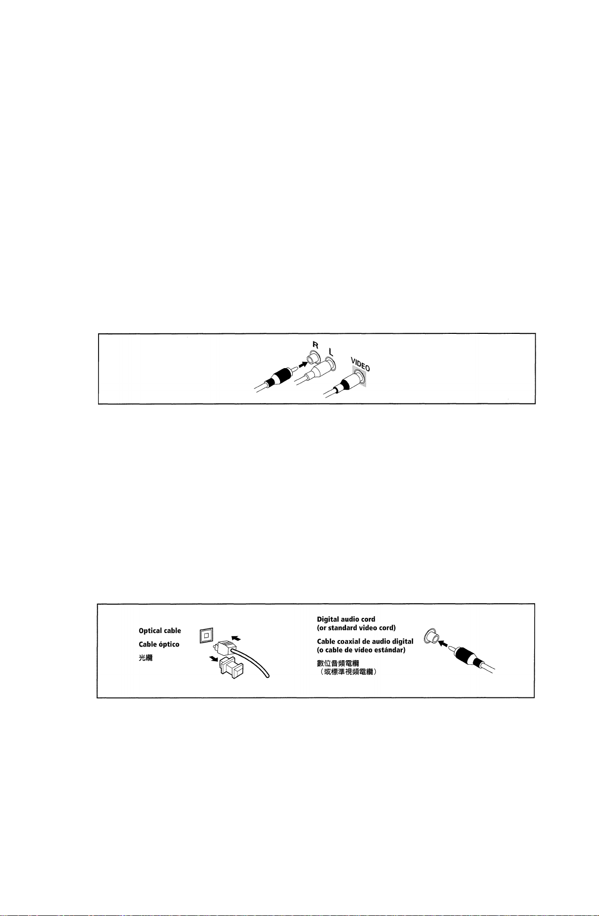
AudioA^ideo Cords
Use audio/video cords (not supplied)
to make analog audio and video
connections.
Connect red plugs to R (right), white
plugs to L (left), and the yellow plugs
to VIDEO.
Be sure to insert completely.
equipo
Antes de realizar o cambiar las
conexiones, apague el aparato y
desconecte el cable de alimentación
de la toma de CA de la pared.
Cables de audio/vídeo
Use cables de audio/vídeo (no
suministrados) para hacer conexiones
de audio y vídeo analógico.
Conecte los enchufes rojos a la toma
R (derecha), los enchufes blancos a al
toma L (izquierda) y los enchufes
rojos a al toma VIDEO.
Asegúrese de insertarlos hasta el
fondo.
±ACfÍPÍgtÍ4 “
m) ^
Wimmmmm (íí) ± > efe
mmmw. (ä) ; u&^feM
íiPjviDEo (mm) ±°
—°
Digital Audio Cords/Optical
Cabies
Commercially available digital audio
coaxial cords (standard video cords
can also be used) or optical cables
(not supplied) are used to connect
digital components to this receiver.
When you use optical digital input or
output terminals, pull off the caps
and insert the plugs. Be sure to insert
completely.
Cables coaxiales de audio
digitaj/cables ópticos
Los cables coaxiales de audio digital
de venta en el comercio (pueden
utilizarse también cables de vídeo
normales) o cables ópticos (no
suministrados) se usan para conectar
los componentes digitales en este
receptor.
Cuando utilice los terminales de
entrada o salida digital ópticos,
desmonte las tapas e inserte los
enchufes. Asegúrese de insertarlos
hasta el fondo.
II myt
11 ’ ÍEStfiTcjf il
B# ’ ñmííLT ’ if gil® A»-
En/Sp/ChH
9

Connecting Digital
Components
In order to use PCM/DD Digital/
DTS soundtracks, you need to
make digital audio connections.
You can do this by either coaxial or
optical connections (you do not need
to do both). The quality of these two
types of connections is the same but
since some digital components only
have one type of digital terminal, it is
a matter of matching like with like
(for example, the coaxial out from the
component to coaxial in on the
receiver). The VSX-D710S/D710S-G
has a coaxial input and two optical
inputs for a total of three digital
inputs. The VSX-D810S/D810S-G has
a coaxial input and three optical
inputs for a total of four digital
inputs. Connect your digital
components as shown below. There is
one digital out jack which is marked
DIGITAL OUT. If you connect this to
the optical input on a digital recorder
(currently these include MD, DAT
and CD-R) you can make direct
digital recordings with this unit.
When connecting your equipment,
always make sure the power is turned
off and the power cord is
disconnected from the wall outlet.
Conexiones digitales
Para utilizar las pistas de sonido
PCM/DG/DTS, deberá hacer
conexiones de audio digital.
Puede hacerlo con una conexión
coaxial o una conexión óptica (no es
necesario hacer ambas). La calidad de
estos dos tipos de conexiones es la
misma, pero como algunos
componentes digitales sólo tienen un
tipo de terminal digital, es necesario
hacerlos corresponder (por ejemplo,
la salida coaxial del componente a la
entrada coaxial del receptor). El VSXD710S/D710S-G tiene una entrada
coaxial y dos ópticas para un total de
tres entradas digitales. El VSX-
D810S/D810S-G tiene una entrada
coaxial y tres ópticas para un total de
cuatro entradas digitales. Se
recomienda conectar sus
componentes como puede apreciar en
la ilustración de abajo. Hay una toma
de salida digital marcada con las
palabras DIGITAL OUT. Si la conecta
a la entrada óptica de una grabadora
digital (actualmente pueden ser MDs,
DAT y CD-R) podrá hacer
grabaciones digitales directas con esta
unidad.
Antes de conectar su equipo,
asegúrese de que el sistema está
apagado y el cable de alimentación
desconectado del enchufe de la pared.
;Í7®fflPCM/Gnlí1uSff/DTSí
i;i ’ jiííuTcfti
fñ] f¡til
íiTtftRW-aSííáíSí ’ HftR
WRIMESB ° {\mw ’ ÍAÉTtfttüíR
±) ° VSX-D710S/D710S-GM^—
ÍSRIÉliAfnffiíiTfcíiflA ’ liÄ
o vsx-
D810S/D810S-GÍIjmW-ffl|S]fÉfÍ
AfDAÍSAfifiA ’ llÄRfÄHii
»föflAffiffl “
№ ° ÍWiWDIGITAL
OUT (SífilitB) lin ’ StIfÄif
P (Sflia®BSii^ßMD’DATS
CD-R) — AtiUBigüiTitföÄ
ftilgtsíifíf ’
MM ’ MMiatilJÍÍgííÉÍIͱACÍf p
The arrows indicate the direction of the
audio signal.
VSX-D710S/D710S-G
10
En/Sp/ChH
Las flechas indican el sentido de la señal
de audio.
lSi^/T^raíi§^K)7□íq] °
CD recorder, MD
or DAT

TV tuner
(or Satellite tuner)
Sintonizador de TV
(o sintonizador para la
Example Connection for
a DVD/LD or LD Player
Since some LDs have soundtracks
recorded on the special □□ RF format
you need to make special hook ups to
ensure you can play all LDs on your
system. If you don’t have an LD (or
an LD player with your DVD player)
you don’t need to worry about this.
For the VSX-D710S/D710S-G/D810S/
D810S-G hook up your DVD/LD or
LD player directly and make sure you
make both a □□ RF output and either
a coaxial or optical digital connection.
Of course you must hook up your
DVD/LD or LD player with standard
(coaxial or optical) digital
connections but if you are able to
hook up your player with a □□ RF
output (if your player has one) this
will ensure you can use all LDs
available. We also recommend
hooking up your digital components
to analog audio jacks as well.
Before making or changing the
connections, switch off the power and
disconnect the power cord from the
AC wall outlet.
Ejemplo de conexión de
un reproductor de DVDs/
LDs o reproductor de LDs
Dado que algunos LDs tienen pistas
de sonido grabadas en un formato RF
□□ especial, necesitará realizar
conexiones especiales para asegurarse
de que puede reproducir todo tipo de
LDs en su sistema. Si no dispone de
un LD (o un reproductor de LDs con
su reproductor de DVDs), esta
información no le es relevante. En los
modelos VSX-D710S/D710S-G/
D810S/D810S-G, conecte su
reproductor de DVDs/LDs o de LDs
directamente y asegúrese de hacer
una salida RF □□ y una conexión
coaxial u óptica digital. Deberá
conectar su reproductor de DVDs/LDs
o de LDs con conexiones digitales
estándar (coaxiales u ópticas), pero si
puede conectar su reproductor con
una salida RF □□ (si su reproductor
tiene una), esto asegurará que puede
usar todo tipo de LDs. También
recomendamos también conectar sus
componentes digitales a tomas de
audio analógicas.
Antes de realizar o cambiar
conexiones, apague el sistema y
desconecte el cable de alimentación
de la toma CA de la pared.
íi) ’ -tíi^ííí’íia»HSvsxD710S/D710S-G/D810S/D81 OS-GE
ígEfÍDVD/LDg(LDfiíStÍ ’
IslWWiiS^liainnRFfitüö^Sfö
mm “
gtíÉílíiDVD/LD^LDffJÍ
íi >
LD o mmmmmmíL7t\mm3\
3f±ACÍÍPÍfitti
11
En/Sp/ChH

Connecting Audio
Components
To begin set up, connect your audio
components to the jacks as shown
below. These are all analog
connections and your analog audio
components (like a cassette deck) use
these jacks. Remember that for
components you want to record with
you need to hook up four plugs (a set
of stereo ins and a set of stereo outs),
but for components that only play
you only need to hook up one set of
stereo plugs (two plugs). To use
digital source features you must hook
up your digital components to the
digital inputs (see the previous page
for more on digital connections) but
it is also a good idea to hook up your
digital components to these analog
audio jacks. If you want to record to/
from digital components (like an MD)
to/from analog components, you must
hook up your digital equipment with
these analog connections.
When connecting your equipment,
always make sure the power is turned
off and the power cord is
disconnected from the wall outlet.
Componentes de audio
Para empezar, conecte sus
componentes de audio en las tomas
como se indica a continuación. Todas
son conexiones analógicas y sus
componentes de audio analógico
(como una platina de cintas) utilizan
estas tomas. Recuerde que para los
componentes con los que desea
grabar, es necesario conectar cuatro
enchufes (un juego de entradas
estéreo y un juego de salidas estéreo),
pero para los componentes que son
sólo para reproducción sólo necesita
conectar un juego de enchufes estéreo
(dos enchufes).
Para utilizar las funciones de sonido
digital, deberá conectar sus
componentes digitales a las entradas
digitales página anterior,
donde se ofrecen más datos sobre las
conexiones digitales), aunque
también recomendamos la conexión
de sus componentes digitales a estas
tomas de audio analógicas. Si desea
grabar a/de las conexiones de
componentes digitales (como un MD)
a/de componentes analógicos, deberá
conectar su equipo digital con estas
conexiones analógicas.
Antes de conectar su equipo,
asegúrese de que el sistema está
apagado y el cable de alimentación
está desconectado del enchufe de la
pared.
’ ílf-hIItt:
»mi ’
«’ i-miimmmxmfmR
mmmm i2imm)
’ mmmiíLTiim
ífS№íifiA± ; (WliKííilíf
tm’mmrnM) »íafEWiTt
Tcft (®MD)
m (MD) —
ffidíSISÍiM > -^1
iW.
vm ’ «?ií.s-tii)iKíiÉ«f±Acap
12
En/Sp/ChH

The arrows indicate the direction of the
audio signal.
Las flechas indican el sentido de la señal
de audio.
Ì5HM/TnM’^ÌÌ5ÌK)7dI^ <
CD player
Reproductor de CDs
cmmm
CD recorder
or Cassette deck
Grabadora de CDs
o platina de cintas
CD player
Reproductor de CDs
CD recorder
or Cassette deck
Grabadora de CDs
o platina de cintas
=fc:Wt»*t№
VSX-D710S/D710S-G
VSX-D810S/D810S-G
/- DIGITAL IN
pcM/oa/OTS
#|IH
COAX I OPT®
m
(CD-R)@
m
Cassette deck placement
Depending on where the cassette
deck is placed, noise may occur
during playback of your cassette deck
which is caused by leakage flux from
the transformer in the receiver. If you
experience noise, move the cassette
deck farther away from the receiver.
Colocación de la platina de cintas
De acuerdo con el lugar donde haya
instalado la platina de cintas, puede
haber ruido durante la reproducción,
provocado por un flujo de fugas del
transformador en el receptor. Si se
escuchan ruidos, aleje la platina de
cintas del receptor.
13
En/Sp/ChH

Connecting DVD 7.1
Channel (5.1 chforVSXD710S/D710S-G)
Components
DVD and LD discs are compatible
with both 2 channel and 7.1 channel
(5.1 channel for VSX-D710S/D710S-
G) audio output formats. Connections
can be made from a DVD player/
multi-channel decoder equipped with
7.1 analog outputs to the 6.1 analog
inputs on this unit (the surround
back channel is mono on the VSXD810S/D810S-G models so we refer
to it as 6.1 ch). You need to connect
both the left and right surround back
channels for the VSX-D810S/D810SG models but the sound from this
channel will only be mono. Always
make sure that the receiver is
switched off and unplugged from the
wall outlet before making or changing
any connections.
Conexión de
componentes DVD 7.1
canales (5.1 canales para
elVSX-D710S/D710S-G)
Los discos de DVD y LD son
compatibles con los formatos de
salida de audio de 2 canales y de 7.1
canales (5.1 canales para el VSXD710S/D710S-G). Las conexiones
pueden efectuarse desde un
decodificador reproductor/multicanal
de DVD equipado con salidas 7.1
análogas a las entradas análogas de
6.1 de este aparato (el canal surround
posterior es monoaural en los
modelos VSX-D810S/D810S-G, por
lo que le llamamos 6.1 ch). Deberá
conectar tanto los canales surround
posteriores izquierdo como el derecho
para los modelos VSX-D810S/D810SG, pero el sonido de este canal sólo se
escuchará en mono. Antes de realizar
o cambiar conexiones, asegúrese de
que el sistema está apagado y
desconectado de la toma de la pared.
mmdw i.imm (vsx-
D710S/D710S-G^5.1«M
) Ttff
DVDfDLD)t5f ISjI
( VSX-D710S/D71 OS-GMS . 1 Sil )
’H’iBîiitÜMîÇ—^10^ °
. m
J:tfÍA± ’ (VSX-D810S/D810S-G
ovsx-
D810S/D810S-Gi!J®iiÈ’^aîlg:è
ts=.iWñímmmm —
’ mummmm > mmmú
±snfrktü °
The arrows indícate the direction of the
audio signal.
Las flechas indican el sentido de la señal
de audio.
mmmrnmmmwÆTjm ^
DVD/muIti channel
decoder with 5.1 channel
analog output jacks
Decodificador de DVDs/
multicanal con tomas de
salida analógicas de
14
En/Sp/ChH

VSX-D810S/D810S-G
Decodificador de DVDs/multicanal con tomas de
salida analógicas de canales 7.1
DVD/^^7.
MEMO:
• The 7.1 channel (5.1 channel for
VSX-D710S/D710S-G) input can
only be used when DVD 7.1 ch
(5.1 channel for VSX-D710S/
D710S-G) input is selected.
• For 6.1 channel output select the
Surround Back Ich setting (see p.
40). In this case you can connect
the single surround back speaker
to either the left or right surround
back terminals.
Connecting Video
Components
Connect your video components to
the jacks as shown below. Regarding
digital video components (like a DVD
player), you must use the analog
video connections pictured on this
page for the video signal but in order
to use a digital source (like a DVD)
you must hook up their audio to a
digital audio input (see p. 10-11). It is
also a good idea to hook up your
digital components with analog audio
connections as well (see p. 12-13).
When connecting your equipment
always make sure the power is turned
off and the power cord is
disconnected from the wall outlet.
MEMO:
• La entrada de 7.1 canales (5.1
canales para el VSX-D710S/D710SG) sólo puede ser utilizada cuando
se selecciona la entrada DVD 7.1
canales (5.1 canales para el VSXD710S/D710S-G).
• Para las salidas de 6.1 canales,
seleccione el valor posterior con
surround Ich (consulte la pg. 40).
En estos casos podrá conectar el
único altavoz surround posterior a
los terminales surround izquierdo o
derecho posteriores.
Conexión de
componentes de vídeo
Conecte sus componentes de vídeo a
las tomas indicadas a continuación.
Con respecto a los componentes de
vídeo digital (un reproductor de
DVDs, por ejemplo) deberá utilizar
las conexiones analógicas de vídeo
que puede apreciar en esta página
para la señal de vídeo, pero para
poder usar una fuente digital (como
un DVD) deberá conectar su audio a
una entrada de audio digital (véanse
las pg. 10-11). Es recomendable
asimismo conectar su componentes
digitales con conexiones de audio
analógico (consulte la pg. 12-13).
mvi ■■
• HWtS5EDVD7.lSiI (VSX-
D710S/D710S-G;g5.1
ttííffl7.1»ÍISA (VSXD710S/D710S-G;^5.iSÍÍ) ”
mmn± ’
DVDfSSiíti) =
rÉ ’ mmamimmmmmn
± ; ($p
DVD) >
’ til
(M®12-13M) “S
)iígiaíi^sjí»iiígfíí > m>mm
’ l|}illtil)«í;íss±
15
En/Sp/ChH

The arrows indicate the direction of the
audio signal.
Las flechas indican el sentido de la señal
de audio.
TV tuner
(or Satellite tuner)
TV tuner
(or Satellite tuner)
VCR
VCR
16
En/Sp/ChH
de LDs)
P)

Front
Front video connections are accessed
via the front panel input selector as
«VIDEO».
Parte frontal
A las conexiones de vídeo delanteras
se accede mediante el selector de
entrada del panel frontal como
«VIDEO».
mmmm
«¡AS
“VIDEO” mm.)
Video camera (etc.)
Cámara de vídeo, etc
mmm m)
MEMO:
This receiver also has S-Video and
component video inputs and outputs.
These can give you a better picture
than the standard composite video
connections. For S-Video connections
use an S-Video cord (not supplied);
for component video connections use
a three-way RCA cord (not supplied).
Note that a signal fed into a video
input on this receiver is only sent to
your TV from the corresponding
video output. In other words, if you
connect your VCR to this receiver
using a standard video cord, you need
to connect the receiver to your TV
using a standard video cord. If your
DVD player is connected using an S-
Video cord, make sure that you also
connect the receiver to your TV with
an S-Video cord.
MEMO:
El receptor dispone también de
entradas y salidas de componente de
vídeo. Éstas pueden darle una mejor
imagen que la que obtendrá con las
conexiones compuestas de vídeo
estándar. Para las conexiones S-Vídeo,
utilice un cable de S-Vídeo (no
suministrado) y para las conexiones
compuestas de vídeo use un cable
RCA de tres vías (no suministrado).
Recuerde que una señal que entra por
una entrada de vídeo en este receptor
sólo se envía a su televisor desde la
salida de vídeo correspondiente. Es
decir, si conecta su reproductor de
vídeo a este receptor utilizando un
cable de vídeo estándar, necesitará
conectar el receptor a su televisor
mediante un cable de vídeo estándar.
Si conecta su reproductor de DVD
con un cable S-Vídeo, asegúrese
también de conectar el receptor a su
televisor con un cable S-Vídeo.
PiíE :
iiiiAfflfMíü « mmmmmm
Mí«) ; TtíWIÍI®JÍf|gfflA.l>
RCA«|i (A^tiMÍ«) »
im : llig?№íg^íítilIHIIAíííi
mm¡\m »
nmmm > *
mmmmmmmnmMimmm.
DVDifffiti ’ sxmM№s-w%ñM
mmmmmm
17
En/Sp/ChH

Connecting Antennas Conexión de antenas
Connect the AM loop antenna and
the FM wire antenna as shown below.
To improve reception and sound
quality, connect external antennas
(see Using External Antennas,
below). Always make sure that the
receiver is switched off and un
plugged from the wall outlet before
making or changing any connections.
VSX-D710S/D710S-G
Conecte la antena de cuadro AM y la
antena de cable FM como se indica en
la siguiente ilustración. Para mejorar
la recepción y la calidad del sonido,
conecte antenas externas (consulte la
sección «Uso de antenas externas»
más abajo). Asegúrese siempre de que
el receptor esté apagado y
desconectado de la toma de la pared
antes de realizar o cambiar las
conexiones.
mm^m
MTffiíSii)
mm ’ immmmm >
íiPTOiÜ“
FM wire antenna
Connect the FM wire antenna and
fully extend vertically along a
window frame or other suitable area,
etc.
AM loop antenna
Assemble the antenna and connect to
the receiver. Attach to a wall, etc. (if
desired) and face in the direction that
gives the best reception.
18
En/Sp/ChH
Antena de cable de FM
Conecte la antena de cable de FM y
extiéndala toda ella en dirección
vertical a lo largo del marco de una
ventana u otra área adecuada, etc.
Antena de cable AM
Monte la antena y conéctela al
receptor. Acóplela a una pared, etc, si
(lo cree conveniente) y diríjala hacia
la dirección en la que obtenga una
mejor recepción.

Antenna snap connectors
Twist the exposed wire strands
together and insert into the hole, then
snap the connector shut.
Conectores de encaje de las
antenas
Doble los filos expuestos del cable e
insértelos por el orificio. A
continuación, encaje a presión el
conector para cerrarlo.
Using External Antennas Uso de antenas externas
ífiíL ’ mkmmm »
To improve FM reception
Connect an external FM antenna.
To improve AM reception
Connect a 5-6 m length of vinylcoated wire to the AM antenna
terminal without disconnecting the
supplied AM loop antenna.
For the best possible reception,
suspend horizontally outdoors.
Cómo mejorar la recepción
en FM
Conecte una antena externa de FM
Cómo mejorar la recepción
en AM
Conecte un cable de 5-6 m. con
revestimiento de vinilo al terminal de
la antena AM sin desconectar la
antena de cable AM.
Para la mejor recepción posible,
suspéndala horizontalmente en el
exterior.
Outdoor antenna
Antena exterior
19
En/Sp/ChH

Connecting Speakers
(VSX-D710S/D710S-G)
A full complement of six speakers is
shown here but, naturally, everyone’s
home setup will vary. Simply connect
the speakers you have in the manner
described right. The receiver will
work with just two stereo speakers
(called «Front» speakers in the
diagram) but we recommend you use
at least three speakers and five is best.
The B speaker system is only for a
pair of stereo speakers.
Make sure you connect the speaker
on the right to the right terminal and
the speaker on the left to the left
terminal. Also make sure the positive
and negative (+/-) terminals on the
receiver match those on the speakers.
MEMO:
• The receiver has two speaker
systems, A & B. A is the main
system supporting the full
complement of surround sound
speakers. If you switch on both A
& B speaker systems, only front
speakers and the subwoofer will
be audible. No sound will come
from the center or surround
speakers but multi channel
sources will be down-mixed to the
active speakers so no sound will
be lost. Similarly, if you choose
just the B system you‘11 only hear
the front speakers connected to
the B system and multi channel
sources will be down-mixed to
these two speakers.
• Use speakers with a nominal
impedance of 8 Q to 16 ii.
Conexión de los
altavoces (VSX-D710S/
D710S-G)
En la siguiente ilustración se muestra
un juego total de seis altavoces pero
por supuesto la instalación de cada
hogar es diferente. El receptor puede
funcionar con sólo dos altavoces
estéreo (llamados «Altavoces
frontales» en la ilustración) pero se
recomienda utilizar como mínimo tres
altavoces, aunque cinco es siempre
mejor.
El sistema de altavoces B es sólo para
un par de altavoces estéreo.
Asegúrese de conectar el altavoz de la
derecha en el terminal de la derecha y
el altavoz de la izquierda en el
terminal izquierdo. Asimismo,
asegúrese de que los terminales
positivo y negativo (+/-) del receptor
coincidan con los de los altavoces.
MEMO:
• El receptor tiene dos sistemas de
altavoces, A y B. A es el sistema
principal que soporta un juego
completo de altavoces de sonido
surround.
sistemas de altavoces A y B, sólo
podrán escucharse los altavoces
frontales y el altavoz realzador
de graves. No saldrá ningún
sonido por los altavoces central
y surround pero las fuentes
multicanal se mezclarán en los
altavoces activos para que no
pierda ningún sonido. De la
misma forma, si elige sólo el
sistema B, sólo podrán escucharse
los altavoces frontales conectados
al sistema B y las fuentes
multicanal se mezclarán en estos
dos altavoces.
• Utilice altavoces con una
impedancia nominal de 8 O —
16a
Si activa ambos
(VSX-D710S/
D710S-G)
. iññ ’
mm’
» immR
“M” usa
o
± “ (V
-) (V-) ti
tSEie »
Plise ^
mmimm »
» mmhm
— Rmm
> mmmmmMT.
M ’ mRmmmmmí’mmm
Wlí PIÎaêsDïiJ 1
20
En/Sp/ChH

Front Speakers (A)
Altavoces frontales (A)
(a)
VSX-D710S/D710S-G
Center Speaker
Altavoz central
c
Surround Speakers
Altavoces SURROUND
Powered subwoofer
Realzador de graves
con alimentación
When using the speaker on your TV as the center
speaker, connect the CENTER PREOUT jack on this unit to
the audio input jack on your TV. In this case, the center
speaker shown is unnecessary.
Cuando utilice el altavoz de su televisor como altavoz
central, conecte la toma CENTER PREOUT a la toma de
entrada de este aparato a la toma de entrada de audio
de su televisor. En estos casos, el altavoz central que
aparece en la ilustración no es necesario.
, íl§:$:^J:B!)CENTER
pREouT}iPi5|^íi^±0gM^iüA}iP4iiug ° mmmu
Be sure to complete all
other connections
before connecting this
unit to the AC power
source.
Asegúrese de
completar todas las
conexiones antes de
conectar este aparato a
una fuente de
alimentación de CA.
21
En/Sp/ChH

Connecting Speakers
(VSX-D810S/D810S-G)
A full complement of seven speakers
is shown here but, naturally,
everyone’s home setup will vary.
Simply connect the speakers you have
in the manner described right. The
receiver will work with just two stereo
speakers (called front speakers in the
diagram) but we recommend you use
at least three speakers. To get the
most out of the VSX-D810S/D810S-G
models hook up all seven speakers,
including a surround back speaker,
the latest advancement in home
theater. You can only hook up one
speaker here as the surround back
channel is mono on the VSX-D810S/
D810S-G models. This is actually 6.1
ch sound but we usually refer to it by
its regular name, 7.1 ch sound. The
two are essentially the same thing
both offering surround back sound. If
you don’t hook up a surround back
speaker you can use that speaker
terminal to hook up your subwoofer.
The B speaker system is only for a
pair of stereo speakers.
Make sure you connect the speaker
on the right to the right terminal and
the speaker on the left to the left
terminal. Also make sure the positive
and negative (+/-) terminals on the
receiver match those on the speakers.
MEMO:
• The receiver has two speaker
systems, A & B. A is the main
system supporting the full
complement of surround sound
speakers.
& B speaker systems, only front
speakers and the subwoofer will
be audible. No sound will come
from the center or surround
speakers but multi channel sources
will be down-mixed to the active
speakers so no sound will be lost.
Similarly, if you choose just the B
system youll only hear the front
speakers connected to the B system
and multi channel sources will be
down-mixed to these two speakers.
• Use speakers with a nominal
impedance of 8 Q to 16 Q.
• If you select subwoofer (SB
SUBWF) in the “surround back
speakers setting mode” (see p.34)
you can hook a subwoofer up to the
surround back speaker terminals. In
this case the terminals will be used
for this “passive subwoofer” and no
surround back sound will come
22
from these terminals.
En/Sp/ChH
If you switch on both A
Conexión de los altavoces
(VSX-D810S/D810S-G)
En la siguiente ilustración se muestra un
juego total de siete altavoces pero por
supuesto la instalación de cada hogar es
diferente. El receptor puede funcionar con
sólo dos altavoces estéreo (llamados
altavoces «Altavoces frontales» en la
ilustración) pero se recomienda utilizar
como mínimo tres altavoces. Para
aprovechar mejor todas las prestaciones de
los modelos VSX-D810S/D810S-G, es
siempre mejor utilizar siete altavoces,
incluyendo un altavoz posterior surround,
lo último para los aficionados al cine en
casa. Aquí sólo puede conectar un altavoz,
puesto que el canal posterior surround es
monoaural en los modelos VSX-D810S/
D810S-G. Esto es sonido de 6.1 canales,
pero en general se le conoce como sonido
de 7.1 canales. Ambos son la misma cosa y
ofrecen sonido posterior surround. Si no
conecta un altavoz posterior surround
puede usar ese terminal de altavoz para
conectar un realzador de graves.
El sistema de altavoces B es sólo para un
par de altavoces estéreo.
Asegúrese de conectar el altavoz de la
derecha en el terminal de la derecha y el
altavoz de la izquierda en el terminal
izquierdo. Asimismo, asegúrese de que los
terminales positivo y negativo (+/-)’:del
receptor coincidan con los de los altavoces.
MEMO:
• El receptor tiene dos sistemas de
altavoces, A y B. A es el sistema
principal que soporta un juego
completo de altavoces de sonido
surround. Si activa ambos sistemas
de altavoces A y B, sólo podrán
escucharse los altavoces frontales y
el altavoz realzador de graves. No
saldrá ningún sonido por los
altavoces central y surround pero las
fuentes multicanal se mezclarán en los
altavoces activos para que no pierda
ningún sonido. De la misma forma, si
elige sólo el sistema B, sólo podrán
escucharse los altavoces frontales
conectados al sistema B y las fuentes
multicanal se mezclarán en estos dos
altavoces.
• Utilice altavoces con una impedancia
nominal de 8 -16
• Si selecciona como opción al realzador
de graves (SB SUBWE) en el «Modo de
configuración de los altavoces
posteriores con surround» (consulte la
pg. 34), podrá conectar un realzador de
graves a los terminales de altavoz
trasero surround. En estos casos, los
terminales serán utilizados para este
«realzador de graves pasivo» y no se
oirá ningún sonido posterior surround
de estos terminales.
(VSX-D810S/D810S-G)
’ iñM. ’
» g®í#vsx-
D810S/D810S-GSyfÉ®á^ft;’cfÍ
íiSH » ÉSÍ;VSX-D810S/D810S-G
mñmpmmmmmmvíLmm
±it^6.ichws “
mmmm ^
’ mmmmmmpm
± ° (V
-) (V-) ti
fflESB »
Piiíie ^
• ’ WA
— Rigii
mmmm > mmwmwÆm
if Eí/lM8dSiJ
(SB SUBWF) » MTilüf

Front Speakers (A)
Altavoces frontales(A)
(a)
Center Speaker
Altavoz centrai
Surround Speakers
Altavoces surround
Surround Back Speaker
Altavoz posterior con surround
[0 e ‘
v’“ 1 jj—
Powered subwoofer
Realzador de graves con
alimentación
/
‘0 e ‘
» 0 0 ‘
/ V
■ e © ‘
‘ © © ‘
y y y..y
When using the speaker on your TV as the
center speaker, connect the CENTER
PREOUT jack on this unit to the audio
input jack on your TV. In this case, the
center speaker shown is unnecessary.
‘ e © i
y …yi.
/ V
Be sure to complete
all other connections
before connecting
this unit to the AC
power source.
Asegúrese de
completar todas las
conexiones antes de
conectar este
aparato a una fuente
de alimentación de
CA.
lu ’
Cuando utilice el altavoz de su televisor
como altavoz central, conecte la toma
CENTER PREOUT a la toma de entrada de
este aparato a la toma de entrada de
audio de su televisor. En estos casos, el
altavoz central que aparece en la
ilustración no es necesario.
«ilB^CENTER PRE0UT}ÍPi5|®íi^J:B!]g
° ’ xmpm
23
En/Sp/ChH
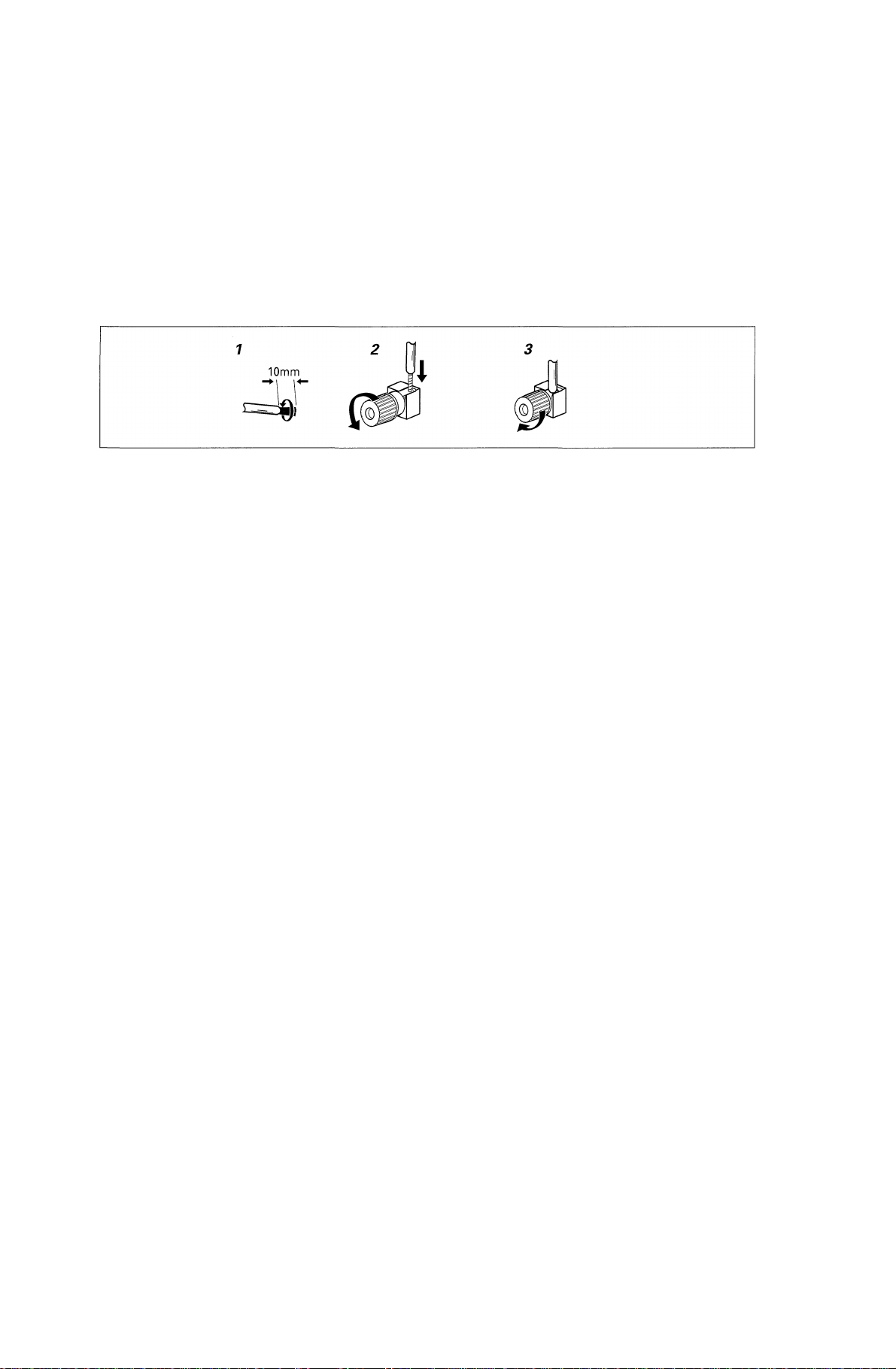
Speaker terminals
1 Twist exposed wire strands 1 Trence los filos del cable para
together. unirlos.
2 Loosen speaker terminal and insert ^ Afloje el terminal del altavoz e
exposed wire inserte el cable que queda
3 Tighten terminal. expuesto
Terminales de los altavoces
3 Apriete el terminal.
1
3
Caution:
Make sure that all the bare speaker
wire is twisted together and inserted
fully into the speaker terminal. If any
of the bare speaker wire touches the
back panel it may cause the power to
cut off as a safety measure.
Hints on Speaker
Placement
Speakers are usually designed with a
particular placement in mind. Some
are designed to be floor standing,
while others should be placed on
stands to sound their best. Some
should be placed near a wall; others
should be placed away from walls.
Follow the guidelines on placement
that the speaker manufacturer
provided with your particular
speakers to get the most out of them.
• Place the front left and right
speakers at equal distances from
the TV.
• When placing speakers near the
TV, we recommend using
magnetically shielded speakers to
prevent possible interference, such
as discoloration of the picture
when the TV is switched on. If you
do not have magnetically shielded
speakers and notice discoloration
of the TV picture, move the
speakers farther away from the TV.
• Install the center speaker above or
below the TV so that the sound of
the center channel is localized at
the TV screen.
Precaución:
Asegúrese de trenzar todo el cable
que queda al descubierto y de que se
inserta totalmente al terminal del
altavoz. Si una porción del cable
desnudo del altavoz toca el panel
posterior, puede provocar un corte en
el suministro como medida de
seguridad.
Consejos para situar
debidamente los altavoces
El diseño de los altavoces siempre
tiene en cuenta la que será su mejor
emplazamiento en una sala. Algunos
altavoces están diseñados para estar
de pie en el suelo, mientras que otros
deberían colocarse en estanterías para
poder obtener su mejor rendimiento
acústico. Algunos deberían colocarse
cerca de una pared, mientras que
otros deben alejarse de ellos. Consulte
las instrucciones que vienen con sus
altavoces y que su fabricante le habrá
entregado para aprovechar al máximo
sus ventajas acústicas.
• Coloque los altavoces derecho e
izquierdo a la distancia del
televisor.
• Cuando coloque los altavoces
cerca del televisor, recomendamos
usar altavoces con resistencia
magnética para evitar posibles
interferencias, como la pérdida de
color en la imagen del televisor al
encenderlo. Si no tiene altavoces
con resistencia magnética y aprecia
una pérdida de color en la imagen
de su televisor, aleje los altavoces
del televisor.
• Instale el altavoz central sobre o
por debajo del televisor para que
el sonido del canal central quede
localizado como la pantalla del
televisor.
/Í/^\
Mimmmmmmmu ’ im-
m »
\mm\mwmmmm > mn±
mèmm
±77gcTT7 ’
24
En/Sp/ChH

CAUTION!
If you choose to install the
center speaker on top of the TV,
be sure to secure it with putty,
or by other suitable means, to
reduce the risk of damage or
injury resulting from the
speaker falling from the TV in
the event of external shocks
such as earthquakes.
• If possible, install the surround
speakers slightly above ear level.
• Try not to install the surround
speakers farther away from the
listening position than the front
and center
speakers. Doing so can weaken the
surround sound effect.
To achieve the best possible surround
sound, install your speakers as shown
on the right. Be sure all speakers are
installed securely to prevent accidents
and improve sound quality.
¡PRECAUCIÓN!
Cuando instale el altavoz
central encima del televisor,
asegúrelo con plastelina
adeherente u otro medio
apropiado ya que el altavoz
puede caerse del televisor
debido a causas externas, por
ejemplo golpes o un terremoto,
lo cual puede poner en peligro
a las personas cercanas o dañar
el altavoz.
• En lo posible, instale los altavoces
surround ligeramente encima del
nivel de los oídos.
• Trate de no instalar los altavoces
surround más alejados de la
posición de audición que los
altavoces frontal y central. De
hacerlo, puede debilitar el efecto
del sonido surround.
Para lograr el mejor efecto surround
posible, instale sus altavoces según se
muestra en la ilustración de la
derecha. Cerciórese de que los
altavoces están instalados de forma
segura para evitar accidentes y
mejorar la calidad del sonido.
/í/€\ !
m-mmmmmmmm
mmnimm ’ mmm ’
^ mji±
25
En/Sp/ChH

Overhead view of speaker set up ~VSX-D710S/D710S-G~
Plano superior de la instalación de altavoces ~VSX-D710S/D710S-G~
-VSX-D710S/D710S-G-
Front Right
Frontal derecho
Front Left
Frontal
izquierdo
Surround Left
Surround izquierdo
ÍÜÍHS
Center
Central
Listening Position
Posición de audición
imm^m
Siu
Subwoofer
Realzador
de graves
-^ñrnmm
Surround Right
Surround derecho
Overhead view mof speaker set up ~VSX-D810S/D810S-G~
Plano superior de la instalación de altavoces ~VSX-D810S/D810S-G-
‘-VSX-D810S/D810S-G-
Front Right
Frontal derecho
Front Left
Frontal
izquierdo
íiu
Center
Central
aiu
Subwoofer
Realzador
de graves
3-D view of speaker set up
Plano tridimensional de los altavoces
3-D view of speaker set up
Plano tridimensional de los altavoces
Surround Left
Surround izquierdo Listening Position
26
En/Sp/ChH
Listening Position
Surround Back
Posterior con surround
Surround Right
Surround
derecho
^mmm

Connecting Additional
Amplifiers (VSX-D810S/
D810S-G oniy)
This receiver has more than
sufficient power for any home use,
however it is possible to add
additional amplifiers to every
channel. Make the connections
shown below to add amplifiers to
power your speakers. Always make
sure that the receiver is switched off
and unplugged from the wall outlet
before making or changing any
connections.
The arrows indicate the direction of the
audio signal.
VSX-D810S/D810S-G
Conexión de
amplificadores
adicionales (sólo VSXD810S/D810S-G)
Este receptor tiene la suficiente
potencia para cualquier uso en el
hogar. Ahora bien, es posible agregar
amplificadores adicionales a cada
canal. Si desea utilizar amplificadores
para activar sus altavoces, haga las
conexiones que indica la ilustración.
Antes de realizar o cambiar las
conexiones, apague el sistema y
desconecte el cable de alimentación
de la toma de la pared.
Las flechas indican el sentido de la señal
de audio.
VSX-D810S/D810S-G)
“ xmmm
Front channel
amplifier
Amplificador del _
canal frontal
Surround channel
amplifier
Amplificador del
canal surround
MEMO:
To hear sound only from the pre-outs,
disconnect any speakers that are
connected directly to the receiver.
(Using the SPEAKERS button to
switch off the speakers also mutes the
pre-outs; you must set it to either A,
B, or A+B.)
MEMO:
Para oír sonido solamente de las salidas
de preamplificación, desconecte todos
los altavoces que estén conectados
directamente al receptor. (Use el botón
SPEAKERS para apagar los altavoces y
enmudecer así a las salidas de
preamplificación. Deberá configurarlo
como A, B o A+B)
Surround Back
channel amplifier
Amplificador del canal
posterior surround
Center channel
amplifier
Amplificador del
canal central
PÍSS5 ^
©iïffifi-îimiiiij»# ’ E
SPEAKERS (ÜSgS) jgffi
lim-tiinlfXM-iîESW ’ ÍIíI-
Powered
Subwoofer
Realzador
de graves
con
alimentación
En/Sp/ChH
27

Operating other Pioneer
Components
By connecting a control cord
(optional), you can control other
Pioneer equipment using the remote
control for this unit. Point the
remote control unit towards the
remote sensor of this unit, even
when operating other equipment.
The remote control signals are
received by the remote sensor of this
unit, and sent to the other devices via
the CONTROL OUT terminal.
MEMO:
• You can also control Pioneer
components by pointing the
receiver’s remote control directly
at the component. This type of
operation does not require control
cords.
• Whenever making the control jack
connections, be sure to also connect
the analog input and output jacks.
System control does not function
correctly when only the digital
input and output connections are
made.
Cómo operar otros
componentes Pioneer
Conectando un cable de control
(opcional) puede controlar otros
equipos Pioneer con esta unidad de
mando a distancia. Apunte el mando
a distancia hacia el sensor a distancia
de esta unidad, incluso si está
operando otro equipo.
Las señales del mando a distancia las
recibe el sensor del mando a distancia
de esta unidad y se envían a los otros
dispositivos a través del terminal
CONTROL OUT
MEMO:
• También puede controlar
componentes Pioneer apuntando
el mando a distancia del receptor
directamente al componente. Este
tipo de operación no requiere
cables de control.
• Al realizar las conexiones de la
toma de control, asegúrese de
conectar también las tomas de
entrada y salida analógicas. El
control del sistema no funciona
correctamente cuando sólo se
realizan las conexiones digitales de
entrada y de salida.
^1T^ítj3P1oneer7EÍT
(ÍÍS) ’
Pioneerg^fji °
iiCONTROLOUT (eSlJfittì)
Sí ’ »
PIÍÍ5 ^
ÌiPioneerTti^SSlJiljcft °
28
En/Sp/ChH
Connect to CONTROL
IN terminai of other
Pioneer products with
■ mark.
Conecte a la terminal
CONTROL IN de otros
productos Pioneer con
la marca Q.
Pioneer^ppÉCONTROL
IN (}^®jiiyA) °

Preparations
Preparaciones
mmxv^
Setting Up for Surround
Sound
Be sure to switch the power of this
unit on (The STANDBY indicator goes
out).
To ensure the best possible surround
sound, be sure to complete the
following set up operations. This is
particularly important when using the
□□ (Dolby)/DTS surround mode. You
only need to make these settings once
(unless you change the placement of
your current speaker system or add
new speakers, etc.). Refer to the
following pages for detailed
descriptions of the settings available
for each mode.
1 Press RECEIVER to turn the
power on.
The STANDBY indicator goes out.
2 Press RCV.
This button switches the remote to
the receiver’s mode.
3 Press < or > to select the
mode you want to set.
For best results, start with
“SPEAKERS setting mode” and
make your initial adjustments in
the order described below.
The current settings are displayed
automatically.
• DTS-ES ON/OFF setting mode
(page 32) (VSX-D810S/D810S-G
only)
Use to turn the DTS-ES (surround
back) channels ON or OFF (for
DTS discs only).
• SPEAKERS (Front, Center,
Surround) setting mode (page
33)
Use to specify the size and type of
speakers you have connected.
• SPEAKERS (Surround Back)
setting mode (page 34) (VSXD810S/D810S-G only)
Use to specify the size and type of
surround back speaker you have
connected or if you have con
nected a subwoofer here.
• SUBWOOFER ON/PLS/OFF
setting mode (page 35)
Use to specify if the subwoofer is set
Preparación para el sonido
surround
Recuerde que el aparato ha de estar
encendido (el indicador STANDBY
desaparece).
Para asegurarse de que el sonido
surround es el óptimo, lleve a cabo las
siguientes operaciones. Esto es
particularmente importante si va a hacer
uso del modo surround □□ (Dolby)/
DTS. Sólo necesita configurar estos
valores una vez (a menos que planee
cambiar la ubicación de su sistema o
añadir nuevos altavoces, etc). Consulte
la información de estas páginas para
obtener una descripción detallada de los
valores de los que dispone en cada
modo.
1 Pulse RECEIVER para encender
el aparato.
Verá desaparecer el indicador
STANDBY.
2 Pulse RCV.
Este botón pone al mando a distancia
en el modo receptor.
3 Pulse < o > para seleccionar el
modo que desee configurar.
Para obtener los mejores resultados,
comience por «Modo de
configuración de los altavoces» y
realice sus ajustes iniciales en el
orden que describimos a
continuación.
Los valores actuales aparecen
automáticamente en pantalla.
• Modo de configuración DTS-ES
ON/OFF (pg. 32) (sólo VSXD810S/D810S-G)
Use para activar (ON) o desactivar
(OFF) los canales DTS-ES
(posteriores con surround). Sólo para
discos DTS.
• Modo de configuración de los
altavoces (frontal, central,
surround) (pg. 33)
Use para especificar el tamaño y el
tipo de altavoces que tiene
conectados.
• Modo de configuración de los
altavoces posteriores con surround
(pg. 34) (sólo VSX-D810S/D810SG)
Use para especificar el tamaño y el
tipo de altavoces posteriores con
surround que tiene conectados o si
tiene conectado aquí un realzador de
graves.
• ON/PLS/OFF del realzador de
graves (pg. 35)
Use para especificar si el realzador de
graves está activado, en valor plus o
desactivado.
J<Kil9cBPXlS
» (STANDBY
(íiffl) immm) »
iiSiSTatsxSifF ° (f±
it) /DTSÍilitiítB# ’
ímmmmmmtmimimm
mmmm) » swiícsmíib
1 ÍSTRECEIVER (íiOT)
STANDBYÍi^H-® o
2 Í^TRCVÍSia»
mmmwmm&mmmití
°
“SPEAKERS (^*§1)
sí” mtá ’ w(!éi)iií5gTaíii
Sfilili °
. DTS-ES ON/OFF (ll/IS)
(S32M) immmm-
D810S/D810S-G)
ffls^üi!ciiDTs-Es mmm)
Sil (ílfflS^DTS^Sf)
. SPEAKERS (it) ‘ ‘ ii,Ü
») (^33M)
. SPEAKERS SSS«
^ (^34H) immmm-
D810S/D810S-G)
SUBWOOFER ON/PLS/OFF
mmim)
29
En/Sp/ChH

to on, plus or off.
• Crossover frequency setting
mode (page 35)
Use to determine which
frequencies will be sent to the
subwoofer (or “Large” speakers if
you don’t have a subwoofer).
• LFE attenuator setting mode
(page 36)
Use to specify the peak level for
the LFE channel and the crossover
network for rerouted bass
frequencies.
• Low cut filter ON/OFF setting
mode (page 36)
Use to cut the distorted sound
from the subwoofer.
• FRONT speakers distance
setting mode (page 37)
Use to specify the distance from
your listening position to your
front speaker.
• CENTER speakers distance
setting mode (page 37)
Use to specify the distance from
your listening position to your
center speaker.
• SURROUND speakers distance
setting mode (page 37)
Use to specify the distance from
your listening position to your
surround speakers.
• SURROUND BACK speakers
distance setting mode (VSXD810S/D810S-G only) (page 38)
Use to specify the distance from
your listening position to your
surround back speaker.
• Dynamic range control setting
mode (page 38)
Use to compress the dynamic range
of the sound track.
• Dual mono setting (page 39)
Use with Dolby Digital software
that has dual mono encoding if
you want to isolate one channel or
listen in this specialized mono
mode.
• Component input 1 setting
(page 40)
Use to specify the video
component connected to this
input.
• Component input 2 setting
(page 40)
Use to specify the video
component connected to this
input.
30
En/Sp/ChH
• Modo de configuración de la
frecuencia de cruce (pg. 35)
Use para determinar qué
frecuencias serán enviadas al
realzador de graves (o altavoces
«Large» si no tiene un realzador de
graves).
• Modo de configuración del
atenuador LFE (pg. 36)
Use para especificar el nivel
máximo del canal LFE y la red de
cruce de las frecuencias graves
reencaminadas.
• ON/OFF del filtro de corte bajo
(pg- 36)
Use para cortar el sonido
distorsionado del realzador de
graves.
• Modo de configuración de la
distancia de los altavoces
frontales (pg. 37)
Use para especificar la distancia
existente desde su posición de
audición a la de su altavoz frontal.
• Modo de configuración de la
distancia de los altavoces
centrales (pg. 37)
Use para especificar la distancia
existente desde su posición de
audición a la de su altavoz central.
• Modo de configuración de la
distancia de los altavoces
surround (pg. 37)
Use para especificar la distancia
existente desde su posición de
audición a las de sus altavoces
surround.
• Modo de configuración de la
distancia de los altavoces
posteriores con surround (sólo
VSX-D810S/D810S-G) (pg. 38)
Use para especificar la distancia
existente desde su posición de
audición a las de sus
Altavoces surround.
• Modo de configuración del
control de la gama dinámica (pg.
38)
Use para comprimir la gama
dinámica de la pista de sonido.
• Configuración del sonido
monoaural dual (pg. 39)
Use junto con el software Dolby
Digital que tiene codificación
monoaural dual si desea aislar un
canal o escuchar música en este
modo monoaural especializado.
• Valor del componente de la
entrada 1 (pg. 40)
Use para especificar el
componente de vídeo conectado a
esta entrada.
• Valor del componente de la
entrada 2 (pg. 40)
Use para especificar el
componente de vídeo conectado a
esta entrada.
> nm
LFE^ag§|g^1Íj)C (^36M)
iiiff)i®ggoN/oFFia®Sít im
36M)
s
(^37
M)
mmmmnmimmmmm
(^37
H)
37M)
mtmmmnmimmmmm
(iifflB$VSX-D810S/D810S-G)
(m38M)
• uüiEHS^jiaiiiisc (^38
«)
mnmimmmmmm»
• (^39H)
mBmmmwmmmmtím
íiKfi ’
• TíftiiAisa:^ (^40M)
• 7L№liA2ia^ (^40H)
Loading…
Скачать
Operating Instructions
AUDIO/VIDEO
MULTI-CHANNEL RECEIVER
VSX-D710S
VSX-D810S
VSX-D850S
VSX-D710SVSX-D810SVSX-D850S
Standby Position
For Canadian model Important Safety Instructions
Introductory Information
Contents
Audio/Video Cords
Connecting Your EquipmentDigital Audio Cords/Optical Cables
Example Connection for a DVD/LD or LD Player
Connecting Your EquipmentMemo
Cassette deck placement Depending on where the cassette
Connecting Audio Components Woofer Center OUT
Connecting DVD 7.1 Channel 5.1 ch for VSX-D710S Components Front
Connecting Video Components AM loop antenna FM wire antenna
Using External AntennasTo improve FM reception
To improve AM reception Front Speakers a Center Speaker Surround Speakers
Connecting Speakers VSX-D710S Front Speakers a Center Speaker
Connecting Speakers VSX-D810S/D850S Connecting Your Equipment Speaker terminals
Hints on Speaker PlacementOverhead view of speaker set up ~VSX-D710S~
View of speaker set up AC Outlet switched 100 W 0.8 a max
Connecting Additional Amplifiers VSX-D810S/D850S onlyDo not Connect a Monitor or TV SET to this Units AC Outlet
Preparations
Setting Up for Surround Sound Choose DTS-ES on or OFF by using the % or fi buttons
Speakers Front, Center, Surround setting mode LFE attenuator setting mode
Preparations Subwoofer ON/PLUS/OFF setting modeLow cut filter ON/OFF setting mode
Crossover frequency setting mode Dynamic range control setting mode
Preparations Surround speakers distance setting modeDual mono setting
Optical digital input 1 setting
Preparations Component input 1 settingComponent input 2 setting
Coaxial digital input setting Press Test Tone to turn off the test tone
Press Test Tone to output the test tone Displays & Controls
Master Volume Display
~ Master Volume LevelDisplays & Controls
ATT
Setup button see
Signal Select seeTV Volume +/- buttons
Master Volume +/- buttons VSX-D850S only
Sound Modes
Standard modeLearning about the Sound Modes
Advanced Theater modes Hall
Sound Modes DSP modesJazz
Dance Sound Modes
Press Signal Select to select Digital Advanced Theater mode Dolby/ DTS mode
Selecting a Sound ModePress DSP Mode to select the sound mode
Surround operation Press Midnight
Midnight Listening Mode Tuning Directly to a Station
Using the TunerMPX mode
Finding a Station Memorizing Stations
Using the TunerRecalling Memorized Stations
Making an Audio or a Video Recording
Making a RecordingRecord Monitor
Making a Digital Recording To cancel the preset mode at any time Press Setup
Recalling Preset CodesControlling the Rest of Your System
Press and hold Setup for three seconds
Switch on the component you want to controlPress and hold Setup for two seconds
Controlling the Rest of Your System Use the % fi buttons to select the brand of the component
Use the @ # buttons to select the Full Library Search mode To cancel the Learning mode at any time Press Setup
Press Setup and hold for three secondsTo cancel Learning setup mode
To program additional operations for the current component Direct Function
Use the @ # buttons to select the Erase modeUse the number buttons to enter
Press the button to be cleared for three seconds Want to check the preset code for
Checking Preset CodesOperating other Pioneer Components
Press the Multi Control button you Buttons Function Components
CD/MD/CD-R/VCR/DVD/LD/DVR Player/Cassette Deck Controls TV Func
Cable TV/Satellite TV/TV/DTV Controls Manufacturer Code
Preset Code List Grundig
MD Player
Misc Audio
TAE Kwang
Satellite Tuner
Cable TV
Additional Information
Troubleshooting Additional Information
Specifications We Want You Listening For a Lifetime
-
Страница 1
Operating Instructions AUDIO/VIDEO MULTI-CHANNEL RECEIVER VSX-D710S VSX-D810S VSX-D850S[…]
-
Страница 2
2 En W ARNING : T O PREVENT FIRE OR SHOCK HAZARD, DO NOT EXPOSE THIS APPLIANCE TO RAIN OR MOISTURE. IMPOR T ANT The lightning flash with arrowhead symbol, within an equilateral triangle, is intended to alert the user to the presence of uninsulated «dangerous voltage» within the product’s enclosure that may be of sufficient magnitude […]
-
Страница 3
3 En READ INSTRUCTIONS — All the safety and operating instructions should be read before the product is operated. RETAIN INSTRUCTIONS — The safety and operating instructions should be retained for future reference. HEED WARNINGS — All warnings on the product and in the operating instructions should be adhered to. FOLLOW INSTRUCTIONS — All o[…]
-
Страница 4
4 En 01 Introductory Information Checking the Supplied Accessories Please check that you’ve received the following supplied accessories: • AM loop antenna • FM wire antenna • Dry Cell Batteries x2 (VSX-D710S/D810S : type AA IEC R6P) (VSX-D850S : type AA IEC LR6) • Remote Control Unit • Operating Instructions Using this Manual This ma[…]
-
Страница 5
5 En 02 01 Introductory Information 4 Checking the Supplied Accessories 4 Using this Manual 4 Installing the Receiver 4 When Making Cable Connections 4 Loading the Batteries 4 Operating Range of Remote Control Unit 4 02 Contents 5 03 Connecting Y our Equipment 6 Audio/Video Cor ds 6 Digital audio Cor ds/Optical Cables 6 Connecting Digital Component[…]
-
Страница 6
6 En L R L R RL S FRONT L R FRONT L R SURROUND CENTER COMPONENT VIDEO DIGITAL IN PCM/ 2 /DTS DIGITAL OUT TO MONTOR TV TO MONTOR TV VCR / DVR VIDEO VIDEO VCR / DVR TO MONITOR TV OUT CONTROL IN AUX CD IN OUT IN IN OUT OUT CD — R / TAPE / MD SURROUND CENTER SUB W. SUB W. PREOUT IN IN IN YP B P R YP B P R S IN S IN S OUT S OUT IN IN IN TV / SAT TV / SA[…]
-
Страница 7
7 En Example Connection for a DVD/LD or LD Player Since some LDs have soundtracks recor ded on the special 2 RF format you need to make special hook ups to ensure you can play all LDs on your system. If you don’t have an LD (or an LD player with your DVD player) you don’t need to worry about this. For the VSX-D710S/D810S/D850S hook up you[…]
-
Страница 8
8 En Connecting Y our Equipment Connecting Audio Components T o begin set up, connect your audio components to the jacks as shown below . These are all analog connections and your analog audio components (like a cassette deck) use these jacks. Remember that for components you want to recor d with you need to hook up four plugs (a set of stereo ins […]
-
Страница 9
9 En Connecting DVD 7.1 Channel (5.1 ch for VSX-D710S) Components DVD and LD discs are compatible with both 2 channel and 7.1 channel audio output formats. Connections can be made from a DVD player/multi-channel decoder equipped with 7.1 analog outputs to the 6.1 analog inputs on this unit (the surr ound back channel is mono on the VSX-D810S/D850S […]
-
Страница 10
10 En L R L R RL S FRONT L R SURROUND CENTER COMPONENT VIDEO DIGITAL IN PCM/ 2 /DTS DIGITAL OUT TO MONTOR TV TO MONTOR TV VCR / DVR VIDEO VIDEO VCR / DVR TO MONITOR TV OUT CONTROL IN AUX CD IN OUT IN IN OUT OUT CD — R / TAPE / MD SURROUND CENTER SUB W. SUB W. PREOUT IN IN IN YP B P R YP B S IN S IN S OUT S OUT IN IN IN TV / SAT TV / SAT DVD/ LD DVD[…]
-
Страница 11
11 En Connecting Antennas Connect the AM loop antenna and the FM wire antenna as shown below . T o impr ove reception and sound quality , connect external antennas (see Using external antennas, below). Always make sure that the receiver is switched of f and unplugged from the wall outlet befor e making or changing any connections. Connecting Y our […]
-
Страница 12
12 En Connecting Y our Equipment Connecting Speakers (VSX-D710S) A full complement of six speakers is shown here but, naturally , everyone ’ s home setup will var y . Simply connect the speakers you have in the manner described below . The receiver will work with just two ster eo speakers (called “ front ” speakers in the diagram) but we reco[…]
-
Страница 13
13 En Connecting Y our Equipment Connecting Speakers (VSX-D810S/D850S) A full complement of seven speakers is shown here but, naturally , everyone ’ s home setup will vary . Simply connect the speakers you have in the manner described below . The receiver will work with just two ster eo speakers (called “ front ” speakers in the diagram) but […]
-
Страница 14
14 En Connecting Y our Equipment 1 T wist exposed wire strands together . 2 Loosen speaker terminal and insert exposed wire. 3 Tighten terminal. Speaker terminals 3/8 in. (10mm) Hints on Speaker Placement Speakers are usually designed with a particular place- ment in mind. Some are designed to be floor standing, while others should be placed on sta[…]
-
Страница 15
15 En Connecting Y our Equipment AC Outlet [switched 100 W (0.8 A) max] Power supplied through this outlet is turned on and of f by the receiver’s POWER switch. T otal electrical power consumption of connected equipment should not exceed 100 W (0.8 A). CAUTION Do not connect a heater , TV , etc. Also, make sure no exposed speaker wire is touch[…]
-
Страница 16
16 En 04 Pr eparations 1 Press RECEIVER to turn the power on. The ST ANDBY indicator goes out. 2 Press RCV . This button switches the remote to the r eceiver’ s surround setup mode. 3 Press @ or # to select the mode you want to set. For best results, start with “SPEAKERS setting mode” and make your initial adjustments in the or der described […]
-
Страница 17
17 En SPEAKERS (Fr ont, Center , Surround) setting mode This setting establishes the size and configuration of the speaker system you have connected. So, for example, here you set whether you have connected surr ound speakers or not, and how big they are. Selecting “ Lar ge ” or “ Small ” will determine how much bass is sent by the receiver[…]
-
Страница 18
18 En Pr eparations Crossover fr equency setting mode Crossover frequency is the point wher e the receiver divides the high and low sounds (the frequencies) between the speakers. Since most smaller speakers can ’ t handle deep bass tones, this setting allows you to send those sounds to the subwoofer (or speakers set to “ Large ” if you don ?[…]
-
Страница 19
19 En Pr eparations SURROUND speakers distance setting mode Use to set the SURROUND speakers distance. Like the CENTER speaker position, the SURROUND speakers may be set in a location closer or farther to your main listening position than the FRONT speakers. Set the distance of the SURROUND speakers accurately to hear sounds coming fr om both FRONT[…]
-
Страница 20
20 En Component input 1 setting T ells the receiver What (DVD player , etc.) is connected to this input. Press % or fi to select the component setting (DVD, TV , VCR or OFF). MEMO: • The initial setting is “ DVD ” . Component input 2 setting T ells the receiver What (TV , player etc.) is connected to this input. Press % or fi to select the […]
-
Страница 21
21 En Pr eparations Optical digital input 4 setting (VSX- D850S only) Here you tell the r eceiver what component you have hooked up to the optical input jack 4. Press % or fi to select the optical digital input 2 (DVD, TV , CD, CD-R, VCR, or OFF). After you assign a component to this digital jack whenever you select that component, for example a C[…]
-
Страница 22
22 En 05 Displays & Contr ols Front P anel 1 N∫m — Û˘,?∫ # $ % ^ & * (! @ 1 2 34 5 7 8 6 9 ~ = 0- 1 ST ANDBY indicator Lights when the receiver is in standby mode (note that the receiver consumes a small amount of power (1W) in standby mode). 2 ST ANDBY/ON button Switches the receiver between on and standby (note that the receiver con[…]
-
Страница 23
23 En Displays & Controls Display 1 SIGNAL SELECT indicators Light to indicate the type of input signal assigned for the current component (see “Fr ont Panel“, 0 SIGNAL SELECT). When the AUTO setting is being used on VSX-D810S & VSX-D850S receivers a set of brackets will appear around the SIGNAL SELECT indicators. 2 DIGITAL : Lights whe[…]
-
Страница 24
24 En Displays & Controls Remote Contr ol (VSX-D710S/D810S) TV TVFUNC MENU VOLUME MASTER VOLUME TV CONTROL AV PRE-PROGRAMMED AND LEARNING REMOTE CONTROL UNIT CHANNEL ENTER ENTER DISC DTV INFO MPX/RETURN DTV ON/OFF DTV MENU D.ACCESS GUIDE ST TUNE TUNE ST CLASS ATT BAND /DTS DSP TEST TONE CH SELECT CH LEVEL FUNCTION SIGNAL SELECT 1¡ 4 ¢ 7 8 3 ?[…]
-
Страница 25
25 En Displays & Controls 0 MENU button Use to access different menus associated with your DVD player . — MASTER VOLUME +/ – buttons Use to set the overall listening volume. = CHANNEL +/ – buttons Use to select the stations of memorized radio frequencies. Also use to skip tracks backwar d or forward on CDs, DVDs, etc. ~ @ # % fi ( TUNE/ST […]
-
Страница 26
26 En Displays & Controls Remote Contr ol (VSX-D850S) 1 LCD display 2 SETUP Indicates that the remote is in Setup mode. 3 SEARCH Indicates that the remote is in preset code Sear ch mode. 4 SEARCH BY BRAND Indicates that the remote is in preset code Sear ch by brand mode. 5 LEARN Indicates that the remote is in Learning mode and ready to learn s[…]
-
Страница 27
27 En Sound Modes Learning about the Sound Modes The sound modes are explained here. There are two cinema modes: 2 ST ANDARD, and ADV ANCED THEA TER. These are designed to be used with multi channel surround sound audio/visual sour ces (like DVDs and LDs). Intrinsic to home theater , these modes can deliver realistic and powerful surround sound tha[…]
-
Страница 28
28 En DSP modes The DSP (Digital Signal Processing) modes allow you to transform your living r oom into a variety of differ ent sonic environments when playing standar d (two-channel) stereo sources, Dolby Pr o Logic sources, and Dolby Digital sources. DSP modes do not work when the speakers ar e off. HALL 1 Simulates the acoustic envir onment of a[…]
-
Страница 29
29 En Switching ANALOG/DIGIT AL Signal Input When you select a function (for example CD) that is only hooked up by a digital connection, then the ANALOG/DIGIT AL signal input switch will automatically choose digital for VSX-D810S/D850S. If you have that function hooked up by both digital and analog connections this switch lets you choose which to l[…]
-
Страница 30
30 En ADV ANCED THEA TER mode ( Dolby/ DTS mode) Switch on the Dolby/DTS mode by pressing the 2 /DTS button. When Dolby/DTS mode is ON, Dolby Pr o Logic, Dolby Digital and DTS, and signal processing is per — formed automatically corresponding to the input signal. Use this button to cycle through the various modes. When the ST ANDARD mode is selecte[…]
-
Страница 31
31 En Sound Modes 1 2 ENTER DISC DTV INFO MPX/RETURN DTV ON/OFF DTV MENU D.ACCESS GUIDE CLASS ATT BAND 1¡ 4 ¢ 7 8 3 ¶ EFFECT DVD VCR CD-R TV RCV TUN TVC CD MIDNIGHT MULTI CONTROL 5.1 / 7.1 RECEIVER SOURCE 1 2 3 4 5 6 7 8 9 0 10 1 Press RCV . This sets the remote to select the sound mode. (Y ou can skip this step when using the controls on the re[…]
-
Страница 32
32 En 07 Using the T uner Finding a Station The following steps show you how to tune in to FM and AM radio broadcasts using the automatic (sear ch) and manual (step) tuning functions. If you alr eady know the exact frequency of the station you want to listen to, see T uning Directly to a Station on this page. Once you are tuned to a station you can[…]
-
Страница 33
33 En Memorizing Stations If you often listen to a particular radio station, it’s convenient to have the receiver stor e the frequency for easy recall whenever you want to listen to that station. This saves the ef fort of manually tuning in each time. The VSX-D710S/D810S/D850S can memorize up to 30 stations, stored in thr ee banks, or classes,[…]
-
Страница 34
34 En 08 Making a Recording Making an Audio or a Video Recording The following steps show you how to make an audio or a video recording fr om the built in tuner , or from an audio or video source connected to the r eceiver (such as a CD player or TV). Recordings can be made to a CD- Recorder , cassette deck, MD, VCR, or DVR deck connected to the CD[…]
-
Страница 35
35 En 09 Controlling the Rest of Y our System Recalling Pr eset Codes The following steps show you how to recall pr eset codes for each MUL TI CONTROL button. Once the preset code is assigned, pressing the button will automatically set the remote to operate the r espective component. MEMO: • Refer to “ Preset Code List ” on pages 43 to 49 for[…]
-
Страница 36
36 En Setting Up Using Pr eset Code Sear ch (VSX-D710S/D810S) An alternative method of setting up the remote with preset codes is to use the sear ch feature. The remote transmits batches of 10 codes; when you see the component responding you just scan thr ough those last 10 codes until you find the correct one. 1 Switch on the component you want to[…]
-
Страница 37
37 En Setting Up Using Brand Name Sear ch (VSX-D850S only) An alternative method of setting up the remote with preset codes is to use the Brand Sear ch feature. The remote transmits batches of 10 codes; when you see the component responding you just scan thr ough those last 10 codes until you find the correct one. 1 Switch on the component you want[…]
-
Страница 38
38 En 5 Point the two r emote controls towards each other . Press the button to be learned on this receiver’ s remote control (for example the 3 [play] button). Point the remote controls dir ectly at each other , about 1-2 inches apart, and press the button on the remote control for the operation you want to pr ogram. The LED flashes rapidly . Fo[…]
-
Страница 39
39 En Er asing One of the Remote Contr ol Button Settings This erases one of the buttons you have pr ogrammed and restor es the factory installed preset to that button. VSX-D710S/D810S: 1 Press SETUP and hold for thr ee seconds. The LED on the remote contr ol will light for two seconds. 2 Press the MUL TI CONTROL button relating to the function of […]
-
Страница 40
40 En Checking Pr eset Codes T o check which preset code is associated with a MUL TI CONTROL button: VSX-D710S/D810S: 1 Press SETUP and hold for thr ee seconds. The LED on the remote contr ol lights for two seconds. 2 Press the MUL TI CONTROL button you want to check the preset code for . 3 Press and hold ENTER for two seconds. Each preset code con[…]
-
Страница 41
41 En CD/MD/CD-R/VCR/DVD/LD/DVR Player/Cassette Deck Contr ols This remote contr ol can contr ol these components after entering the proper codes or teaching the r eceiver the commands (see p.35-37). Use MUL TI CONTROL buttons to put the remote control in the stated mode. Contr olling the Rest of Y our System ) s ( n o t t u Bn o i t c n u Fs t n e[…]
-
Страница 42
42 En Cable TV/Satellite TV/TV/DTV Contr ols This remote contr ol can control these components after entering the pr oper codes or teaching the receiver the commands (see p.35-37). Use MUL TI CONTROL buttons to put the remote control in the stated mode. MEMO: • The first four buttons for the VSX-D710S/D810S/D850S are dedicated to contr ol the TV […]
-
Страница 43
43 En Pr eset Code List Y ou can only set these codes for the buttons that assigned to the respective components. So, for example, the TV codes can only be set to the TV or TVC button. Contr olling the Rest of Y our System TV Manufacturer Code PHILIPS 1008, 1017, 1020 1025, 1104, 1115 SONY 1001, 1007, 1016 P ANASONIC 1023, 1054, 1055 1075, 1076, 10[…]
-
Страница 44
44 En Contr olling the Rest of Y our System GRUNDIG 1031, 1066, 1068 1072, 1115 GRUNPY 1063, 1064 HALLMARK 1062 HANSEA TIC 1017, 1098 HARLEY DAVIDSON 1063 HARVARD 1029, 1064 HARMAN/KARDON 1025 HCM 1006, 1090, 1105 HINARI 1006, 1016, 1017 1080 HISAW A 1090, 1111 HIT ACHI 1014, 1016, 1018 1020, 1021, 1026 1044, 1046, 1047 1055, 1069, 1070 1079, 1081,[…]
-
Страница 45
45 En SINDYNE 1043, 1075, 1095 SIGNA TURE 1009 SILVER 1016 SKY 1017 SKY -WORTH 1017 SOLA VOX 1014, 1055 SONITRON 1074 SONOKO 1006, 1017 SONOLOR 1055, 1074, 1077 SONTEC 1017 SOUNDESIGN 1062, 1063, 1064 SOUNDWA VE 1017, 1106 SQUAREVIEW 1059 ST ANDARD 1006, 1079, 1080 ST ARLITE 1064 STERN 1055, 1073, 1088 SUNKAI 1095, 1099 SUPERTECH 1078 SUPREME 1001 […]
-
Страница 46
46 En Contr olling the Rest of Y our System REALISTIC 5025, 5026, 5045 REVOX 5021 ROTEL 5021, 5045 SAE 5021 SANSUI 5021, 5033, 5038 SANYO 5025, 5039 SCHNEIDER 5018 SCOTT 5038 SEARS 5038 SHARP 5008, 5026, 5058 SHERWOOD 5015, 5026, 5031 SONY 5001, 5027, 5050 SOUDESIGN 5019 T ASCAM 5045 TEAC 5024, 5026, 5044 5045 TECHNICS 5004, 5034, 5037 THORENS 5021[…]
-
Страница 47
47 En FISHER 2025, 2026, 2030 2037 FRONTECH 2011 FUJI 2015 FUNAI 2001 GARRARD 2001 GE 2015, 2027, 2032 2057 GEC 2035 GENERAL 2011, 2028 GOLDHAND 2034 GOLDST AR 2017, 2018, 2053 2079 GOODMANS 2001, 2017, 2034 2059, 2075 GO VIDEO 2077, 2081 GRAETZ 2005, 2021, 2037 2057 GRANADA 2025, 2035, 2037 GRADIENTE 2001, 2008 GRANDIN 2001, 2017, 2034 HANSEA TIC […]
-
Страница 48
48 En Contr olling the Rest of Y our System MGA 2023, 2057 MGN TECHNOLOGY 2057 MINCRV A 2048 MINERVA 2005, 2010, 2048 MINOL T A 2022 MOTOROLA 2015, 2027 MTC 2001, 2057 MUL TITECH 2001, 2034 MURPHY 2001 NAD 2031 NA TIONAL 2054 NEC 2018, 2020, 2021 2033, 2037 NECKERMANN 2035 NESCO 2034 NIKKO 2017 NIKON 2014 NOBLEX 2057 NOKIA 2021, 2025, 2037 2038, 20[…]
-
Страница 49
49 En Contr olling the Rest of Y our System FINLUX 4005, 4024, 4032 4037 FRACARRO 4061 FREECOM 4034 FUBE 4030, 4031, 4034 G-SA T 4009 GALAXIS 4019, 4057, 4060 GENERAL INSTRUMENT 4012 GOLD BOX 4059 GOODING 4048 GOODMANS 4010 GRUNDIG 4008, 4010, 4048 HINARI 4009 HIRSCHMANN 4008, 4032, 4039 4040, 4049 HIT ACHI 4037 HOUSTON 4053 HUTH 4013, 4015, 4019 4[…]
-
Страница 50
50 En 10 Additional Information The power does not turn ON. • Connect the power plug to the wall outlet. • Disconnect the power plug fr om the outlet, and inser t again. • Make sure there ar e no loose strands of speaker wire touching the rear panel. This could cause the r eceiver to shut of f automatically . The unit does not respond when th[…]
-
Страница 51
51 En Additional Information Specifications +0 –3 Amplifier Section Continuous average power output of 100 watts (VSX-D850S is 110 watts)* per channel, min., at 8 ohms, fr om 20 Hz to 20,000 Hz with no more than 0.2 %** total harmonic distortion (front). Continuous Power Output (VSX-D710S/D810S) Front …………… 100 W per channel (1kHz, 1.0 […]
-
Страница 52
Published by Pioneer Corporation. Copyright © 2000 Pioneer Corporation. All rights reserved. <XRB3004-A> PIONEER CORPORATION 4-1, Meguro 1-Chome, Meguro-ku, Tokyo 153-8654, Japan PIONEER ELECTRONICS [USA] INC. P.O. BOX 1540, Long Beach, California 90801-1540, U.S.A. PIONEER ELECTRONICS OF CANADA, INC. 300 Allstate Parkway, Markham, Ontario L[…]