
42 страницы подробных инструкций и пользовательских руководств по эксплуатации на русском
Подключение
11
Ru
• Если имеется проигрыватель LD, для воспроизведения дисков LD формата 2 RF необходимо выполнить
специальную настройку. Подключите проигрыватель DVD или LD непосредственно к демодулятору RF
через гнездо выхода 2 RF и коаксиальный либо оптический цифровой кабель. Также рекомендуется
дополнительно подключить цифровые компоненты к гнездам аналогового аудиовыхода. Убедитесь, что
переключатель цифрового входа демодулятора RF установлен в правильное положение
(соответствующее оптическому или коаксиальному соединению). За более подробными сведениями о
входных и выходных разъемах цифрового компонента обратитесь к его инструкции по эксплуатации.
Подключение аудиокомпонентов
Начните настройку с подключения аналоговых аудиокомпонентов (например, кассетной деки) к гнездам. Если
на компоненте предполагается делать запись, подключите его к ресиверу четырьмя разъемами (парой
стереовходов и парой стереовыходов). Если же компонент служит только для воспроизведения, необходимо
подключить лишь одну пару стереоразъемов. Кроме того, необходимо подключить цифровые компоненты к
гнездам аналогового аудио, если требуется выполнять запись с цифровых компонентов (например,
минидиска) на аналоговые или наоборот. Подробнее о цифровом подключении см. стр. 10.
При подключении оборудования обязательно отключайте питание и отсоединяйте кабель питания от
электророзетки.
• Стрелки указывают направление аудио сигнала.
* На рисунке показана модель VSX-D814, но соединения для модели VSX-D714 аналогичны.
Подключение 5.1-канальных DVD-компонентов
Если для декодирования дисков DVD используется отдельный компонент, декодер или проигрыватель DVD с
многоканальными аналоговыми выходами можно подключить к многоканальным входам данного ресивера.
При подключении оборудования обязательно отключайте питание и отсоединяйте кабель питания от
электророзетки.
• Стрелки указывают направление сигнала.
* На рисунке показана модель VSX-D814, но соединения для модели VSX-D714 аналогичны.
• Многоканальный вход можно использовать, только если выбран режим
DVD 5.1 ch (см. стр. 24).
Подключение видеокомпонентов
Подключите видеокомпоненты к гнездам, как показано ниже. В случае цифровых видеокомпонентов
(например, проигрывателя DVD) для передачи видеосигнала следует использовать схему подключения,
приведенную на этой странице, а для прослушивания цифрового источника (например, диска DVD) следует
подключить аудиокомпонент к цифровому входу (см. стр. 10). Рекомендуется также подключить цифровые
компоненты к гнездам аналогового аудио (см. выше).
Чтобы получить видеоизображение наивысшего качества, можно использовать вместо обычных
видеоразъемов гнезда компонентного видео или гнезда S-video (с некоторым ухудшением качества) на задней
панели ресивера. Убедитесь, что эти гнезда подключены к гнездам того же типа на видеокомпоненте.
При подключении оборудования обязательно отключайте питание и отсоединяйте кабель питания от
электророзетки.
• Стрелки указывают направление сигнала.
* На рисунке показана модель VSX-D814, но соединения для модели VSX-D714 аналогичны.
Примечание
ASSIGNABLE
MONITOR OUT
Y
PB
PR
Y
PB
PR
DVR/
VCR
T V /
SAT
DVD
/LD
CONTROL
OUT
IN
AM
LOOP
FM UNBAL
75
Ω
IN
IN
IN
IN
IN
IN
COMPONENT VIDEO
MONITOR
OUT
MONITOR OUT
SUB WOOFER
SURROUND
CEN-
TER
S-VIDEO
OUT
OUT
VIDEO
SUB
WOOFER
R
AUDIO
L
IN
IN
IN
IN
IN
OUT
DIGITAL OUT
OUT
IN
OPT
OPT
COAX
COAX
OPT
AUX
CD
L
R
DVR/
VCR
TV /
SAT
(TV /
SAT)
( D V R / V C R )
(DVD
/LD)
(CD)
DVD
/LD
PLAY
CD-R
/ TAPE
/ MD
FRONT
PREOUT
ASSIGNABLE
DIGITAL IN
REC
1
2
1
2
ø
ANTENNA
(T V / SAT) IN
DVD 5.1CH INPUT
( D V D / LD) IN
¥
A
FRONT
R
L
CENTER
R
L
SURROUND BACK
S I N G L E
S
P
E
A
K
E
R
S
F
SEE INSTRUCTION
MANUAL
D V D
5.1CH
INPUT
REC
PLAY
L
R
L
R
OUTPUT
Этот ресивер*
Проигрыватель
компакт-дисков
Дека CD-R/
кассетная/MD
ASSIGNABLE
MONITOR OUT
Y
PB
PR
Y
PB
PR
DVR/
VCR
T V /
SAT
DVD
/LD
CONTROL
OUT
IN
AM
LOOP
FM UNBAL
75
Ω
IN
IN
IN
IN
IN
IN
COMPONENT VIDEO
MONITOR
OUT
MONITOR OUT
SUB WOOFER
SURROUND
CEN-
TER
S-VIDEO
OUT
OUT
VIDEO
SUB
WOOFER
R
AUDIO
L
IN
IN
IN
IN
IN
OUT
DIGITAL OUT
OUT
IN
OPT
OPT
COAX
COAX
OPT
AUX
CD
L
R
DVR/
VCR
TV /
SAT
(TV /
SAT)
( D V R / V C R )
(DVD
/LD)
(CD)
DVD
/LD
PLAY
CD-R
/ TAPE
/ MD
FRONT
PREOUT
ASSIGNABLE
DIGITAL IN
REC
1
2
1
2
ø
ANTENNA
(T V / SAT) IN
DVD 5.1CH INPUT
( D V D / LD) IN ¥
PREOUT
A
B
FRONT
R
L
R
R
R
L
R
L
FRONT
CENTER
SURROUND
R
L
L
L
SURROUND BACK
S I N G L E
S
P
E
A
K
E
R
S
FRONT
CENTER
SURROUND
BACK
SURROUND
SEE INSTRUCTION
MANUAL
D V D
5.1CH
INPUT
CENTER
OUTPUT
SUB
WOOFER
OUTPUT
VIDEO
OUTPUT
SURROUND
OUTPUT
L
R
FRONT
OUTPUT
L
R
Этот ресивер*
DVD/многоканальный
декодер с многоканальными
аналоговыми выходами.
Примечание
ASSIGNABLE
MONITOR OUT
Y
PB
PR
Y
PB
PR
DVR/
VCR
T V /
SAT
DVD
/LD
CONTROL
OUT
IN
AM
LOOP
FM UNBAL
75
Ω
IN
IN
IN
IN
IN
IN
COMPONENT VIDEO
MONITOR
OUT
MONITOR OUT
SUB WOOFER
SURROUND
CEN-
TER
S-VIDEO
OUT
OUT
VIDEO
SUB
WOOFER
R
AUDIO
L
IN
IN
IN
IN
IN
OUT
DIGITAL OUT
OUT
IN
OPT
OPT
COAX
COAX
OPT
AUX
CD
L
R
DVR/
VCR
TV /
SAT
(TV /
SAT)
( D V R / V C R )
(DVD
/LD)
(CD)
DVD
/LD
PLAY
CD-R
/ TAPE
/ MD
FRONT
PREOUT
ASSIGNABLE
DIGITAL IN
REC
1
2
1
2
ø
ANTENNA
(T V / SAT) IN
DVD 5.1CH INPUT
( D V D / LD) IN ¥
PREOUT
A
FRONT
R
L
R
R
R
L
CENTER
SURROUND
R
L
L
L
SURROUND BACK
S I N G L E
S
P
E
A
K
E
R
S
FRONT
CENTE
SURROUN
BAC
SURROUND
SEE INSTRUCTION
MANUAL
D V D
5.1CH
INPUT
OUTPUT
VIDEO
L
R
OUTPUT
INPUT
VIDEO
L
R
VIDEO
L
R
OUTPUT
VIDEO
L
R
INPUT
VIDEO
Этот ресивер*
Видеодека
Телевизионный тюнер
(или спутниковый тюнер)
Проигрыватель DVD
или LD
Телевизор
(монитор)
VSX-D714_Ru_A5New.book Page 11 Monday, May 24, 2004 9:10 AM

Подключение к видеоразъему на передней панели, Подключение антенн, Проволочная антенна fm
Рамочная антенна ам, Использование внешних антенн, Speakers, Multi jog, Antenna dvd 5.1ch input, D v d 5.1ch input, Ωantenna Чат поддержки
- Изображение
- Текст
Подключение
12
Ru
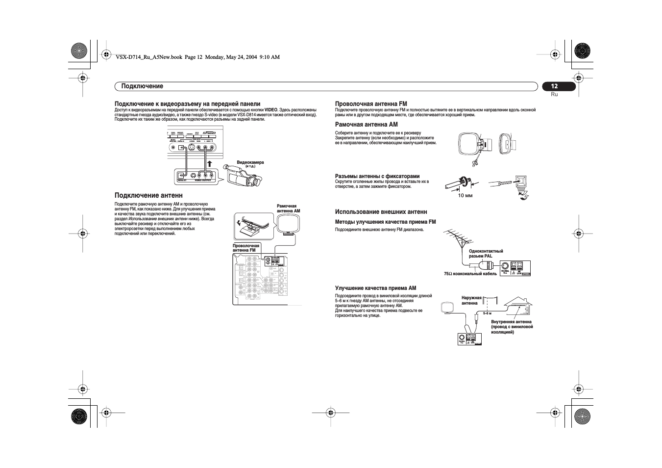
Подключение к видеоразъему на передней панели
Доступ к видеоразъемам на передней панели обеспечивается с помощью кнопки
VIDEO. Здесь расположены
стандартные гнезда аудио/видео, а также гнездо S-video (в модели VSX-D814 имеется также оптический вход).
Подключите их таким же образом, как подключаются разъемы на задней панели.
Подключение антенн
Проволочная антенна FM
Подключите проволочную антенну FM и полностью вытяните ее в вертикальном направлении вдоль оконной
рамы или в другом подходящем месте, где обеспечивается хороший прием.
Рамочная антенна АМ
Использование внешних антенн
Методы улучшения качества приема FM
Улучшение качества приема AM
Подключите рамочную антенну АМ и проволочную
антенну FM, как показано ниже. Для улучшения приема
и качества звука подключите внешние антенны (см.
раздел
Использование внешних антенн ниже). Всегда
выключайте ресивер и отключайте его из
электророзетки перед выполнением любых
подключений или переключений.
SPEAKERS
S-VIDEO
DIGITAL IN
VIDEO
L AUDIO R
O/
T
SIGNAL
SELECT
MIDNIGHT/
LOUDNESS
SB CH
MODE
TONE
QUICK SETUP
SETUP MIC
MCACC
VIDEO INPUT
MULTI JOG
L
V
R
VIDEO OUTPUT
DIGITAL OUT
Видеокамера
(и т.д.)
DVR/
VCR
T V /
SAT
DVD
/LD
CONTROL
OUT
IN
AM
LOOP
FM UNBAL
75
Ω
IN
IN
IN
IN
IN
IN
MONITOR
OUT
MONITOR OUT
SUB WOOFER
SURROUND
CEN-
TER
S-VIDEO
OUT
OUT
VIDEO
SUB
WOOFER
R
AUDIO
L
IN
IN
IN
IN
IN
OUT
DIGITAL OUT
OUT
IN
OPT
OPT
COAX
COAX
OPT
AUX
CD
L
R
DVR/
VCR
TV /
SAT
(TV /
SAT)
( D V R / V C R )
(DVD
/LD)
(CD)
DVD
/LD
PLAY
CD-R
/ TAPE
/ MD
FRONT
PREOUT
ASSIGNABLE
DIGITAL IN
REC
1
2
1
2
ANTENNA
DVD 5.1CH INPUT
A
F
R
S
P
E
A
K
E
R
S
D V D
5.1CH
INPUT
Рамочная
антенна AМ
Проволочная
антенна FM
Соберите антенну и подключите ее к ресиверу
Закрепите антенну (если необходимо) и расположите
ее в направлении, обеспечивающем наилучший прием.
Разъемы антенны с фиксаторами
Скрутите оголенные жилы провода и вставьте их в
отверстие, а затем зажмите фиксатором.
Подсоедините внешнюю антенну FM диапазона.
Подсоедините провод в виниловой изоляции длиной
5–6 м к гнезду AM антенны, не отсоединяя
прилагаемую рамочную антенну AM.
Для наилучшего качества приема подвесьте ее
горизонтально на улице.
10 мм
AM
LOOP
FM UNBAL
75
Ω
ANTENNA
Одноконтактный
разьем PAL
75
Ω
коаксиальный кабель
AM
LOOP
FM UNBAL
75
Ω
ANTENNA
Наружная
антенна
Внутренняя антенна
(провод с виниловой
изоляцией)
5–6 м
VSX-D714_Ru_A5New.book Page 12 Monday, May 24, 2004 9:10 AM
Подсоединение громкоговорителей (vsx- d714), Подсоединение громкоговорителей (vsx- d814), D v d 5.1ch input
Страница 13 Чат поддержки
- Изображение
- Текст
Подключение
13
Ru
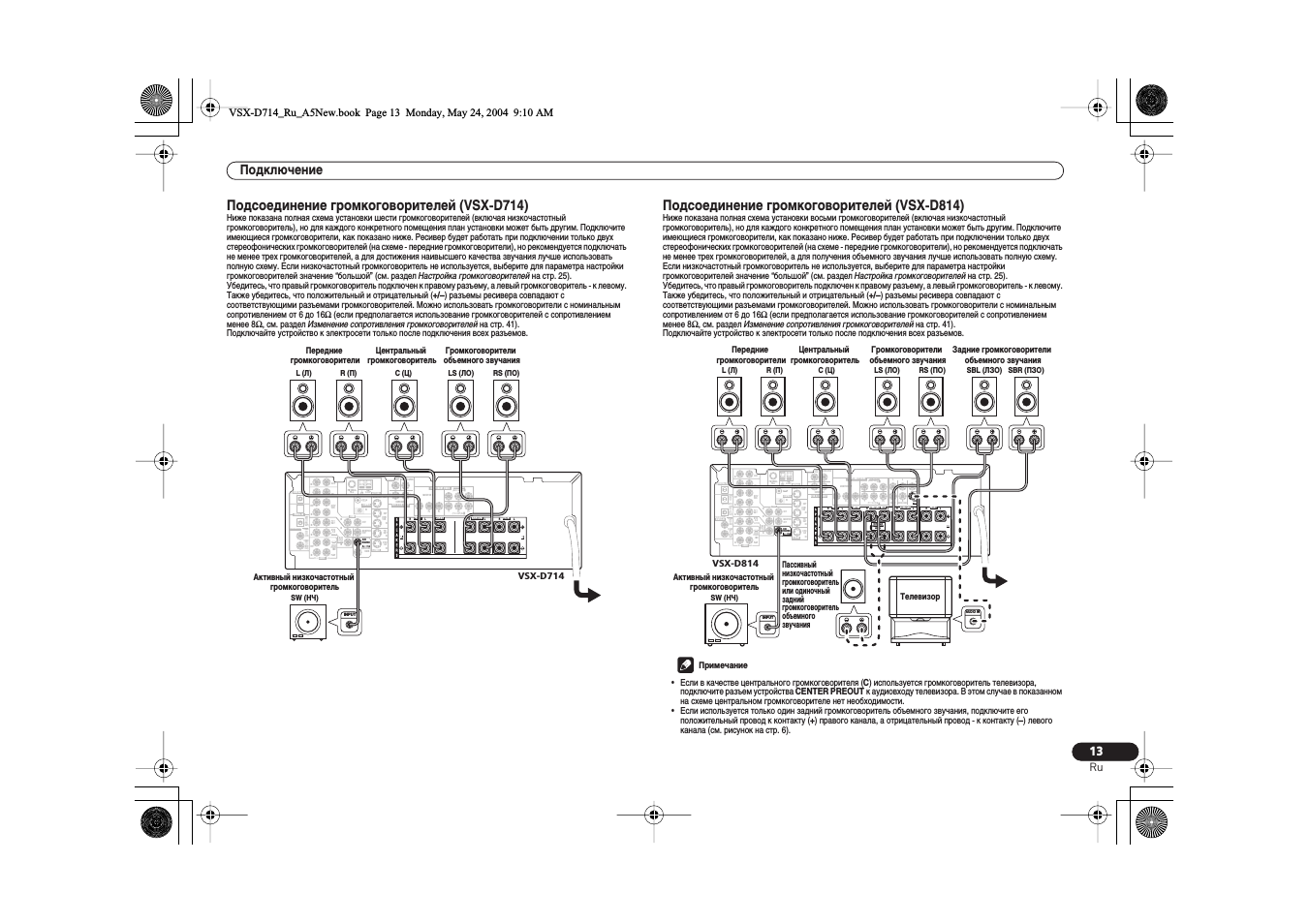
Подсоединение громкоговорителей (VSX-D714)
Ниже показана полная схема установки шести громкоговорителей (включая низкочастотный
громкоговоритель), но для каждого конкретного помещения план установки может быть другим. Подключите
имеющиеся громкоговорители, как показано ниже. Ресивер будет работать при подключении только двух
стереофонических громкоговорителей (на схеме — передние громкоговорители), но рекомендуется подключать
не менее трех громкоговорителей, а для достижения наивысшего качества звучания лучше использовать
полную схему. Если низкочастотный громкоговоритель не используется, выберите для параметра настройки
громкоговорителей значение “большой” (см. раздел
Настройка громкоговорителей на стр. 25).
Убедитесь, что правый громкоговоритель подключен к правому разъему, а левый громкоговоритель — к левому.
Также убедитесь, что положительный и отрицательный (
+/–) разъемы ресивера совпадают с
соответствующими разъемами громкоговорителей. Можно использовать громкоговорители с номинальным
сопротивлением от 6 до 16
Ω
(если предполагается использование громкоговорителей с сопротивлением
менее 8
Ω
, см. раздел
Изменение сопротивления громкоговорителей на стр. 41).
Подключайте устройство к электросети только после подключения всех разъемов.
Подсоединение громкоговорителей (VSX-D814)
Ниже показана полная схема установки восьми громкоговорителей (включая низкочастотный
громкоговоритель), но для каждого конкретного помещения план установки может быть другим. Подключите
имеющиеся громкоговорители, как показано ниже. Ресивер будет работать при подключении только двух
стереофонических громкоговорителей (на схеме — передние громкоговорители), но рекомендуется подключать
не менее трех громкоговорителей, а для получения объемного звучания лучше использовать полную схему.
Если низкочастотный громкоговоритель не используется, выберите для параметра настройки
громкоговорителей значение “большой” (см. раздел
Настройка громкоговорителей на стр. 25).
Убедитесь, что правый громкоговоритель подключен к правому разъему, а левый громкоговоритель — к левому.
Также убедитесь, что положительный и отрицательный (
+/–) разъемы ресивера совпадают с
соответствующими разъемами громкоговорителей. Можно использовать громкоговорители с номинальным
сопротивлением от 6 до 16
Ω
(если предполагается использование громкоговорителей с сопротивлением
менее 8
Ω
, см. раздел
Изменение сопротивления громкоговорителей на стр. 41).
Подключайте устройство к электросети только после подключения всех разъемов.
• Если в качестве центрального громкоговорителя (
C) используется громкоговоритель телевизора,
подключите разъем устройства
CENTER PREOUT к аудиовходу телевизора. В этом случае в показанном
на схеме центральном громкоговорителе нет необходимости.
• Если используется только один задний громкоговоритель объемного звучания, подключите его
положительный провод к контакту (
+) правого канала, а отрицательный провод — к контакту (–) левого
канала (см. рисунок на стр. 6).
ASSIGNABLE
MONITOR OUT
Y
PB
PR
Y
PB
PR
DVR/
VCR
T V /
SAT
DVD
/LD
CONTROL
OUT
IN
AM
LOOP
FM UNBAL
75
Ω
IN
IN
IN
IN
IN
IN
COMPONENT VIDEO
MONITOR
OUT
MONITOR OUT
SUB WOOFER
SURROUND
CEN-
TER
S-VIDEO
OUT
OUT
VIDEO
SUB
WOOFER
SURROUND
BACK
R
AUDIO
L
IN
IN
IN
IN
IN
OUT
DIGITAL OUT
OUT
IN
OPT
COAX
COAX
OPT
AUX
CD
L
R
DVR/
VCR
TV /
SAT
(TV /
SAT)
(DVD
/LD)
(CD)
DVD
/LD
PLAY
CD-R
/ TAPE
/ MD
FRONT
PREOUT
ASSIGNABLE
DIGITAL IN
REC
1
1
2
ø
ANTENNA
(T V / SAT) IN
DVD 5.1CH INPUT
( D V D / LD) IN ¥
A
B
FRONT
R
L
R
L
R
L
FRONT
CENTER
SURROUND
D V D
5.1CH
INPUT
INPUT
VSX-D714
Передние
громкоговорители
Активный низкочастотный
громкоговоритель
SW (НЧ)
Центральный
громкоговоритель
Громкоговорители
объемного звучания
L (Л)
R (П)
C (Ц)
LS (ЛО)
RS (ПО)
ASSIGNABLE
MONITOR OUT
Y
PB
PR
Y
PB
PR
DVR/
VCR
T V /
SAT
DVD
/LD
CONTROL
OUT
IN
AM
LOOP
FM UNBAL
75
Ω
IN
IN
IN
IN
IN
IN
COMPONENT VIDEO
MONITOR
OUT
MONITOR OUT
SUB WOOFER
SURROUND
CEN-
TER
S-VIDEO
OUT
OUT
VIDEO
SUB
WOOFER
R
AUDIO
L
IN
IN
IN
IN
IN
OUT
DIGITAL OUT
OUT
IN
OPT
OPT
COAX
COAX
OPT
AUX
CD
L
R
DVR/
VCR
TV /
SAT
(TV /
SAT)
( D V R / V C R )
(DVD
/LD)
(CD)
DVD
/LD
PLAY
CD-R
/ TAPE
/ MD
FRONT
PREOUT
ASSIGNABLE
DIGITAL IN
REC
1
2
1
2
ø
ANTENNA
(T V / SAT) IN
DVD 5.1CH INPUT
( D V D / LD) IN ¥
PREOUT
A
B
FRONT
R
L
R
R
R
L
R
L
FRONT
CENTER
SURROUND
R
L
L
L
SURROUND BACK
S I N G L E
FRONT
CENTER
SURROUND
BACK
SURROUND
SEE INSTRUCTION
MANUAL
D V D
5.1CH
INPUT
INPUT
AUDIO IN
VSX-D814
Пассивный
низкочастотный
громкоговоритель
или одиночный
задний
громкоговоритель
объемного
звучания
SBL (ЛЗО) SBR (ПЗО)
Задние громкоговорители
объемного звучания
Передние
громкоговорители
Активный низкочастотный
громкоговоритель
SW (НЧ)
Центральный
громкоговоритель
Громкоговорители
объемного звучания
L (Л)
R (П)
C (Ц)
LS (ЛО)
RS (ПО)
Телевизор
Примечание
VSX-D714_Ru_A5New.book Page 13 Monday, May 24, 2004 9:10 AM
Подключение
14
Ru
• Если в разделе
Настройка задних громкоговорителей объемного звучания на стр. 26 выбран
низкочастотный громкоговоритель (
SB SW), можно подключить этот громкоговоритель к контактам
разъемов, предназначенных для задних громкоговорителей объемного звучания. Подключите
положительный провод к контакту (
+) правого канала, а отрицательный провод — к контакту (–) левого
канала (см. рисунок на стр. 6).
Контакты громкоговорителей
1
Скрутите оголенные жилы провода.
2
Ослабьте зажим контакта громкоговорителя и вставьте оголенный провод.
Оголенные концы провода громкоговорителя должны быть обязательно скручены и вставлены в контакт
громкоговорителя до конца. В случае контакта оголенного провода громкоговорителя с задней панелью при
включении питания, питание может отключиться в качестве меры предосторожности. Для подключения
громкоговорителей к ресиверу используйте провод хорошего качества.
3
Зажмите контакт.
Акустические системы A и B
Ресивер оснащен двумя акустическими системами: A и B. A — основная система, которая может работать с
полным набором громкоговорителей. Если включить обе системы — A и B — звук будет исходить только из
передних громкоговорителей и низкочастотного громкоговорителя (если он подключен). Центральный,
боковые и задние громкоговорители объемного звучания не будут работать, но сигналы от многоканальных
источников будут смешиваться в работающих громкоговорителях, так что ни один компонент сигнала не будет
потерян для слушателя. Аналогично, если выбрать систему B, звук будет слышен только из передних
громкоговорителей, подключенных к системе B, и сигналы от многоканальных источников будут смешиваться
в этих двух громкоговорителях.
•
Для выбора акустической системы (A, B или обеих) нажмите кнопку SPEAKERS
(ГРОМКОГОВОРИТЕЛИ) на передней панели.
Советы по расположению громкоговорителей
Обычно при изготовлении громкоговорителей учитывается их предстоящее расположение. Одни
предназначены для напольного размещения, наилучшее звучание других достигается их расположением на
стойках. Некоторые следует располагать у стен, другие — на расстоянии от них. Приведенные здесь
рекомендации предназначены для получения наилучшего качества звучания громкоговорителей, однако, для
максимального использования возможностей громкоговорителей следует выполнять указания по
расположению, приведенные их изготовителем.
• Расположите передние левый и правый громкоговорители на одинаковом расстоянии от телевизора.
• В случае расположения громкоговорителей около телевизора рекомендуется использовать
громкоговорители магнитозащищенного типа, чтобы избежать возможных помех, таких как изменение
цвета изображения при включении телевизора. Если громкоговорителей магнитозащищенного типа нет
и на экране телевизора заметно искажение цветов, отодвиньте громкоговорители от телевизора.
• Расположите центральный громкоговоритель под телевизором или над ним, чтобы звук центрального
канала исходил от экрана телевизора.
• По возможности, располагайте громкоговорители объемного звучания немного выше уровня ушей.
• Старайтесь не размещать громкоговорители объемного звучания дальше от слушателя, чем передние и
центральные. В противном случае может произойти ослабление эффекта объемного звучания.
• Для получения наилучшего качества объемного звучания установите громкоговорители, как показано
ниже. Для предотвращения несчастных случаев и улучшения качества звучания выполняйте надежную
установку всех громкоговорителей.
• Если центральный громкоговоритель размещен над телевизором, обязательно закрепите его с
помощью специального материала или любым другим подходящим способом, чтобы избежать травмы
или повреждений в результате падения громкоговорителя с телевизора, вызванного внешними
сотрясениями, например землетрясением.
• Проверьте, чтобы оголенные провода от громкоговорителей не касались задней панели — это может
вызвать автоматическое выключение ресивера.
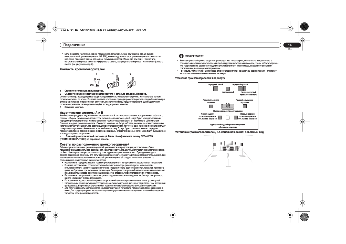
Установка громкоговорителей: вид сверху
Установка громкоговорителей, 6.1-канальная схема: объемный вид
1
2
3
10 мм
Предупреждение
Передний левый
Передний правый
Центральный
Низкочастотный
громкоговоритель
Левый объемного
звучания
Правый объемного
звучания
Положение для прослушивания
Одиночный задний громкоговоритель
объемного звучания
Левый задний
громкоговоритель
объемного звучания
Правый задний
громкоговоритель
объемного звучания
VSX-D714_Ru_A5New.book Page 14 Monday, May 24, 2004 9:10 AM
Подключение
15
Ru
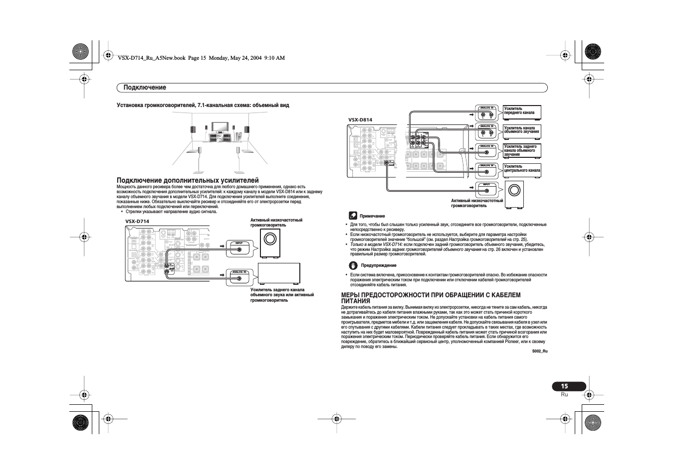
Установка громкоговорителей, 7.1-канальная схема: объемный вид
Подключение дополнительных усилителей
Мощность данного ресивера более чем достаточна для любого домашнего применения, однако есть
возможность подключения дополнительных усилителей: к каждому каналу в модели VSX-D814 или к заднему
каналу объемного звучания в модели VSX-D714. Для подключения усилителей выполните соединения,
показанные ниже. Обязательно выключайте ресивер и отсоединяйте его от электророзетки перед
выполнением любых подключений или переключений.
• Стрелки указывают направление аудио сигнала.
• Для того, чтобы был слышен только усиленный звук, отсоедините все громкоговорители, подключенные
непосредственно к ресиверу.
• Если низкочастотный громкоговоритель не используется, выберите для параметра настройки
громкоговорителей значение “большой” (см. раздел
Настройка громкоговорителей на стр. 25).
•
Только в модели VSX-D714: если подключен задний громкоговоритель объемного звучания, убедитесь,
что режим
Настройка задних громкоговорителей объемного звучания на стр. 26 включен и установлен
правильный размер громкоговорителей.
• Если система включена, прикосновение к контактам громкоговорителей опасно. Во избежание опасности
поражения электрическим током при подключении или отключении кабелей громкоговорителей
отсоединяйте кабель питания.
МЕРЫ ПРЕДОСТОРОЖНОСТИ ПРИ ОБРАЩЕНИИ С КАБЕЛЕМ
ПИТАНИЯ
Держите кабель питания за вилку. Вынимая вилку из электророзетки, никогда не тяните за сам кабель, никогда
не дотрагивайтесь до кабеля питания влажными руками, так как это может стать причиной короткого
замыкания и поражения электрическим током. Не допускайте установки на кабель питания самого
проигрывателя, предметов мебели и т.д. или защемления кабеля. Не допускайте связывания кабеля в узел или
его спутывания с другими кабелями. Кабели питания следует прокладывать в таких местах, где возможность
наступить на них будет маловероятной. Поврежденный кабель питания может стать причиной возгорания или
поражения электрическим током. Периодически проверяйте кабель питания. Если обнаружится его
повреждение, обратитесь в ближайший сервисный центр, уполномоченный компанией Pioneer, или к своему
дилеру по поводу его замены.
S002_Ru
ASSIGNABLE
MONITOR OUT
Y
PB
PR
Y
PB
PR
DVR/
VCR
T V /
SAT
DVD
/LD
CONTROL
OUT
IN
AM
LOOP
FM UNBAL
75
Ω
IN
IN
IN
IN
IN
IN
COMPONENT VIDEO
MONITOR
OUT
MONITOR OUT
SUB WOOFER
SURROUND
CEN-
TER
S-VIDEO
OUT
OUT
VIDEO
SUB
WOOFER
SURROUND
BACK
R
AUDIO
L
IN
IN
IN
IN
IN
OUT
DIGITAL OUT
OUT
IN
OPT
COAX
COAX
OPT
AUX
CD
L
R
DVR/
VCR
TV /
SAT
(TV /
SAT)
(DVD
/LD)
(CD)
DVD
/LD
PLAY
CD-R
/ TAPE
/ MD
FRONT
PREOUT
ASSIGNABLE
DIGITAL IN
REC
1
1
2
ø
ANTENNA
(T V / SAT) IN
DVD 5.1CH INPUT
( D V D / LD) IN
¥
A
B
FRONT
R
L
R
L
R
L
FRONT
CENTER
SURROUND
S
P
E
A
K
E
R
S
D V D
5.1CH
INPUT
ANALOG IN
INPUT
Усилитель заднего канала
объемного звука или активный
громкоговоритель
VSX-D714
Активный низкочастотный
громкоговоритель
ASSIGNABLE
MONITOR OUT
Y
PB
PR
Y
PB
PR
DVR/
VCR
T V /
SAT
DVD
/LD
CONTROL
OUT
IN
AM
LOOP
FM UNBAL
75
Ω
IN
IN
IN
IN
IN
IN
COMPONENT VIDEO
MONITOR
OUT
MONITOR OUT
SUB WOOFER
SURROUND
CEN-
TER
S-VIDEO
OUT
OUT
VIDEO
SUB
WOOFER
R
AUDIO
L
IN
IN
IN
IN
IN
OUT
DIGITAL OUT
OUT
IN
OPT
OPT
COAX
COAX
OPT
AUX
CD
L
R
DVR/
VCR
TV /
SAT
(TV /
SAT)
( D V R / V C R )
(DVD
/LD)
(CD)
DVD
/LD
PLAY
CD-R
/ TAPE
/ MD
FRONT
PREOUT
ASSIGNABLE
DIGITAL IN
REC
1
2
1
2
ø
ANTENNA
(T V / SAT) IN
DVD 5.1CH INPUT
( D V D / LD) IN ¥
PREOUT
A
B
FRONT
R
L
R
R
R
L
R
L
FRONT
CENTER
SURROUND
R
L
L
L
SURROUND BACK
S I N G L E
S
P
E
A
K
E
R
S
FRONT
CENTER
SURROUND
BACK
SURROUND
SEE INSTRUCTION
MANUAL
D V D
5.1CH
INPUT
ABLE
PR
ø
) IN
) IN ¥
PREOUT
B
R
R
R
L
R
L
FRONT
SURROUND
L
L
L
OUND BACK
N G L E
FRONT
CENTER
SURROUND
BACK
SURROUND
NSTRUCTION
MANUAL
ANALOG IN
ANALOG IN
ANALOG IN
INPUT
ANALOG IN
L
R
L
R
Усилитель
переднего канала
Усилитель канала
объемного звучания
Усилитель заднего
канала объемного
звучания
Усилитель
центрального канала
VSX-D814
Активный низкочастотный
громкоговоритель
Примечание
Предупреждение
VSX-D714_Ru_A5New.book Page 15 Monday, May 24, 2004 9:10 AM
Подключение
16
Ru
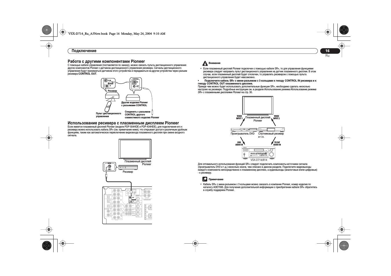
Работа с другими компонентами Pioneer
С помощью кабеля управления (поставляется по заказу), можно связать пульты дистанционного управления
других компонентов Pioneer с датчиком дистанционного управления ресивера. Сигналы дистанционного
управления будут приниматься датчиком этого устройства и передаваться на другие устройства через разъем
ресивера
CONTROL OUT.
Использование ресивера с плазменным дисплеем Pioneer
Если имеется плазменный дисплей Pioneer (модели PDP-504HDE и PDP-434HDE), для подключения его к
ресиверу можно использовать кабель SR+ (см. примечание ниже), что открывает доступ к различным удобным
функциям, таким как автоматическое переключение видеовхода плазменного дисплея при смене входного
сигнала.
• Если плазменный дисплей Pioneer подключен с помощью кабеля SR+, то для управления функциями
ресивера следует направить пульт дистанционного управления на датчик плазменного дисплея. В этом
случае, если плазменный дисплей будет отключен, то управлять ресивером с помощью пульта
дистанционного управления будет невозможно.
•
Подключите кабель SR+ с мини-разъемом с 3 кольцами к гнезду CONTROL IN ресиверa и к
гнезду CONTROL OUT плазменного дисплея.
Прежде чем можно будет использовать дополнительные функции SR+, необходимо сделать несколько
настроек на ресивере. Подробные инструкции см. в разделе Использование режима
Использование режима
SR+ с плазменными дисплеями Pioneer на стр. 30.
Для оптимального использования функций SR+ следует подключить компоненты-источники сигнала
(проигрыватель DVD и т.д.) несколько иначе, чем описано в данном разделе. Подключите видеовыходы
каждого компонента непосредственно к плазменному дисплею, а аудиовыходы (аналоговые и/или цифровые)
— к ресиверу.
• Кабель SR+ с мини-разъемом с 3 кольцами можно заказать в компании Pioneer, номер изделия по
каталогу ADE7095. Для получения дополнительной информации о приобретении кабеля SR+ обратитесь
в службу поддержки Pioneer.
CONTROL
OUT
IN
OUT
IN
CONTROL
Ресивер
Пульт дистанционного
управления
Другие изделия Pioneer
с разъемами CONTROL
Соединить с разъемом
CONTROL другого
совместимого изделия Pioneer
DVR/
VCR
T V /
SAT
DVD
/LD
CONTROL
OUT
IN
AM
LOOP
FM UNBAL
75
Ω
IN
IN
IN
IN
IN
IN
MONITOR
OUT
MONITOR OUT
SUB WOOFER
SURROUND
CEN-
TER
S-VIDEO
OUT
OUT
VIDEO
SUB
WOOFER
R
AUDIO
L
IN
IN
IN
IN
IN
OUT
DIGITAL OUT
OUT
IN
OPT
OPT
COAX
COAX
OPT
AUX
CD
L
R
DVR/
VCR
TV /
SAT
(TV /
SAT)
( D V R / V C R )
(DVD
/LD)
(CD)
DVD
/LD
PLAY
CD-R
/ TAPE
/ MD
FRONT
PREOUT
ASSIGNABLE
DIGITAL IN
REC
1
2
1
2
ANTENNA
DVD 5.1CH INPUT
A
R
S
P
E
A
K
E
R
S
D V D
5.1CH
INPUT
OUT
CONTROL
Плазменный дисплей
Pioneer
Ресивер
Внимание
VSX-D714/814
Плазменный дисплей
Pioneer
Спутниковый ресивер
и т.п.
VIDEO
INPUT 1
VIDEO
INPUT 2
TV/SAT
AUDIO IN
DVD
AUDIO IN
Проигрыватель DVD
UP
DOWN
MULTI JOG
MASTER VOLUME
ENTER
STANDBY/ON
PHONES
DVD/LD
TV/SAT
DVR/VCR
VIDEO
CD
CD-R/
TAPE/MD
TUNER
AUX
STATION
STANDARD
SPEAKERS
S-VIDEO
DIGITAL IN
SETUP MIC
VIDEO
L AUDIO R
ADVANCED
SURROUND
STEREO/
DIRECT
SIGNAL
SELECT
MIDNIGHT/
LOUDNESS
SB CH
MODE
TUNING
LISTENING MODE
TONE
QUICK SETUP
TUNER EDIT
CLASS
BAND
MPX
MULTI JOG
PTY
SEARCH
EON
MODE
MCACC
VIDEO INPUT
MULTI JOG
Примечание
VSX-D714_Ru_A5New.book Page 16 Monday, May 24, 2004 9:10 AM
Органы управления и индикаторы
17
Ru
Глава 5:
Органы управления и индикаторы
Передняя панель
1
STANDBY/ON (ОЖИДАНИЕ/ВКЛ.)
Используется для включения ресивера или его переключения в режим ожидания.
2
Кнопки выбор входа
Нажмите одну из этих кнопок для выбора источника сигнала.
3
Датчик дистанционного управления
Получает сигналы от пульта дистанционного управления.
4
Индикатор MCACC
Загорается после завершения настройки MCACC (стр. 28 для модели VSX-D814 также стр. 9).
5
ENTER (ВВОД)
6
Регулятор MULTI JOG
С помощью регулятора
MULTI JOG выполняется множество задач. Используйте для выбора параметров
после нажатия кнопок
TONE (ТЕМБР), QUICK SETUP (БЫСТРАЯ НАСТРОЙКА) или TUNER EDIT
(ТЮНЕР — РЕДАКТИРОВАТЬ).
7
MASTER VOLUME (РЕГУЛЯТОР ГРОМКОСТИ)
8
Гнездо PHONES (ГОЛОВНЫЕ ТЕЛЕФОНЫ)
Используется для подключения головных телефонов. При подключении головных телефонов звук не будет
воспроизводиться через громкоговорители.
9
Кнопки STATION +/– (СТАНЦИЯ +/–)
Нажимайте эти кнопки для выбора запрограммированных станций при использовании тюнера (стр. 32).
10 Кнопки TUNING +/– (НАСТРОЙКА +/–)
Нажимайте эти кнопки для выбора частоты при использовании тюнера (стр. 31).
11 Кнопки LISTENING MODE (РЕЖИМ ПРОСЛУШИВАНИЯ)
STANDARD (СТАНДАРТ)
Нажмите эту кнопку для стандартного декодирования и переключения между различными параметрами
Pro Logic II и Neo:6 (стр. 21).
ADVANCED SURROUND (ДОПОЛНИТЕЛЬНОЕ ОБЪЕМНОЕ ЗВУЧАНИЕ)
Используется для переключения между различными режимами объемного звучания (стр. 21).
STEREO/DIRECT (СТЕРЕО/ПРЯМОЕ)
Переключатель прямого/стереофонического воспроизведения. При прямом воспроизведении для
наиболее точной передачи входного сигнала настройки тембра и уровня каналов не учитываются
(стр. 22).
12 SIGNAL SELECT (ВЫБОР СИГНАЛА)
Используется для выбора источника входного сигнала (стр. 22).
13 MIDNIGHT/LOUDNESS (НОЧНОЙ/СИЛА ЗВУКА)
Режим Midnight (Ночной) используется для прослушивания звукового сопровождения к фильмам при малой
громкости. Режим Loudness (Сила звука) служит для усиления низких и высоких частот при малой громкости
(стр. 23).
14 SPEAKERS (ГРОМКОГОВОРИТЕЛИ)
Служит для последовательного выбора акустической системы:
A
B
A+B (стр. 14)
15 SB CH MODE (РЕЖИМ ОБЪЕМНОГО ЗВУЧАНИЯ)
Служит для выбора режима заднего канала объемного звучания (стр. 22) и режима виртуальных задних
громкоговорителей объемного звучания (VSB) (стр. 23).
16 TONE (ТЕМБР)
Нажмите эту кнопку для использования регуляторов низких и высоких частот, которые можно регулировать с
помощью
MULTI JOG (стр. 24).
17 QUICK SETUP (БЫСТРАЯ НАСТРОЙКА)
См. раздел
Использование быстрой настройки на стр. 7.
18 VIDEO INPUT (ВИДЕОВХОД)
См. раздел
Подключение к видеоразъему на передней панели на стр. 12.
19 DIGITAL IN (ЦИФРОВОЙ ВХОД)
Только для модели VSX-D814
См. раздел
Подключение к видеоразъему на передней панели на стр. 12.
20 MCACC SETUP MIC (МИКРОФОН НАСТРОЙКИ MCACC)
Только для модели VSX-D814
К гнезду
MCACC SETUP MIC (МИКРОФОН НАСТРОЙКИ MCACC) подключается микрофон, входящий в
комплект поставки системы, при использовании автоматической настройки объемного звучания (MCACC)
(стр. 9).
21 EON MODE (РЕЖИМ EON)
Используется для поиска различных станций, передающих новости или информацию о движении транспорта
(этот способ поиска называется EON) (стр. 33).
22 PTY SEARCH (ПОИСК ТИПА ПРОГРАММЫ)
Используйте для поиска различных типов программ в режиме RDS (стр. 33).
23 MPX (МОНО)
Нажмите эту кнопку для приема радиопередач в монофоническом режиме (стр. 31).
24 BAND (ДИАПАЗОН)
Переключение радиодиапазонов AM — FM (стр. 31).
25 CLASS (КЛАСС)
Используется для выбора одного из трех банков (классов) запрограммированных радиостанций (стр. 31).
26 TUNER EDIT (ТЮНЕР — РЕДАКТИРОВАТЬ)
Нажмите эту кнопку, чтобы сохранить станцию и присвоить ей название для перехода к ней (стр. 31).
UP
DOWN
MULTI JOG
MASTER VOLUME
ENTER
AUDIO/VIDEO MULTI-CHANNEL RECEIVER
VSX-D914
STANDBY/ON
PHONES
DVD/LD
TV/SAT
DVR/VCR
VIDEO
CD
CD-R/
TAPE/MD
TUNER
AUX
STATION
STANDARD
SPEAKERS
S-VIDEO
MCACC
DIGITAL IN
SETUP MIC
VIDEO
VIDEO INPUT
L AUDIO R
ADVANCED
SURROUND
STEREO/
DIRECT
SIGNAL
SELECT
MIDNIGHT/
LOUDNESS
SB CH
MODE
TUNING
LISTENING MODE
TONE
QUICK SETUP
TUNER EDIT
CLASS
BAND
MPX
MULTI JOG
MULTI JOG
PTY
SEARCH
EON
MODE
SPEAKERS
S-VIDEO
PUSH
OPEN
DIGITAL IN
VIDEO
L AUDIO R
SB CH
MODE
TONE
QUICK SETUP
MIDNIGHT/
LOUDNESS
SIGNAL
SELECT
MULTI JOG
MCACC
SETUP MIC
VIDEO INPUT
1
2
8
5
6
3
4
7
9
26 25 24 23 22 21
18
10
11
12 13
14 15 16
17
19
20
VSX-D714_Ru_A5New.book Page 17 Monday, May 24, 2004 9:10 AM

Органы управления и индикаторы
18
Ru
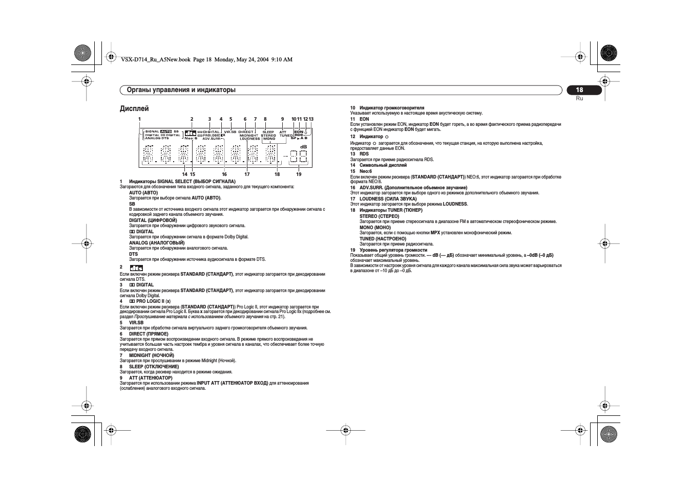
Дисплей
1
Индикаторы SIGNAL SELECT (ВЫБОР СИГНАЛА)
Загораются для обозначения типа входного сигнала, заданного для текущего компонента:
AUTO (АВТО)
Загорается при выборе сигнала
AUTO (АВТО).
SB
В зависимости от источника входного сигнала этот индикатор загорается при обнаружении сигнала с
кодировкой заднего канала объемного звучания.
DIGITAL (ЦИФРОВОЙ)
Загорается при обнаружении цифрового звукового сигнала.
2 DIGITAL
Загорается при обнаружении сигнала в формате Dolby Digital.
ANALOG (АНАЛОГОВЫЙ)
Загорается при обнаружении аналогового сигнала.
DTS
Загорается при обнаружении источника аудиосигнала в формате DTS.
2
Если включен режим ресивера
STANDARD (СТАНДАРТ), этот индикатор загорается при декодировании
сигнала DTS.
3
2 DIGITAL
Если включен режим ресивера
STANDARD (СТАНДАРТ), этот индикатор загорается при декодировании
сигнала Dolby Digital.
4
2 PRO LOGIC II (x)
Если включен режим ресивера (
STANDARD (СТАНДАРТ)) Pro Logic II, этот индикатор загорается при
декодировании сигнала Pro Logic II. Буква
x загорается при декодировании сигнала Pro Logic IIx (подробнее см.
раздел
Прослушивание материала с использованием объемного звучания на стр. 21).
5
VIR.SB
Загорается при обработке сигнала виртуального заднего громкоговорителя объемного звучания.
6
DIRECT (ПРЯМОЕ)
Загорается при прямом воспроизведении входного сигнала. В режиме прямого воспроизведения не
учитывается большая часть настроек тембра и уровня сигнала в каналах, что обеспечивает более точную
передачу входного сигнала.
7
MIDNIGHT (НОЧНОЙ)
Загорается при прослушивании в режиме Midnight (Ночной).
8
SLEEP (ОТКЛЮЧЕНИЕ)
Загорается, когда ресивер находится в режиме ожидания.
9
ATT (АТТЕНЮАТОР)
Загорается при использовании режима
INPUT ATT (АТТЕНЮАТОР ВХОД) для аттенюирования
(ослабления) аналогового входного сигнала.
10 Индикатор громкоговорителя
Указывает используемую в настоящее время акустическую систему.
11 EON
Если установлен режим EON, индикатор
EON будет гореть, а во время фактического приема радиопередачи
с функцией EON индикатор
EON будет мигать.
12 Индикатор
Индикатор
загорается для обозначения, что текущая станция, на которую выполнена настройка,
предоставляет данные EON.
13 RDS
Загорается при приеме радиосигнала RDS.
14 Символьный дисплей
15 Neo:6
Если включен режим ресивера (
STANDARD (СТАНДАРТ)) NEO:6, этот индикатор загорается при обработке
формата NEO:6.
16 ADV.SURR. (Дополнительное объемное звучание)
Этот индикатор загорается при выборе одного из режимов дополнительного объемного звучания.
17 LOUDNESS (СИЛА ЗВУКА)
Этот индикатор загорается при выборе режима
LOUDNESS.
18 Индикаторы TUNER (ТЮНЕР)
STEREO (СТЕРЕО)
Загорается при приеме стереосигнала в диапазоне FM в автоматическом стереофоническом режиме.
MONO (МОНО)
Загорается, если с помощью кнопки
MPX установлен монофонический режим.
TUNED (НАСТРОЕНО)
Загорается при приеме радиосигнала.
19 Уровень регулятора громкости
Показывает общий уровень громкости.
— dB (— дБ) обозначает минимальный уровень, а –0dB (–0 дБ)
обозначает максимальный уровень.
В зависимости от настроек уровня сигнала для каждого канала максимальная сила звука может варьироваться
в диапазоне от –10 дБ до –0 дБ.
EON
SP
A B
RDS
x
1
2
3
4
5
6
13
7
8
9
11 12
10
14
19
17
16
15
18
VSX-D714_Ru_A5New.book Page 18 Monday, May 24, 2004 9:10 AM
Органы управления и индикаторы
19
Ru
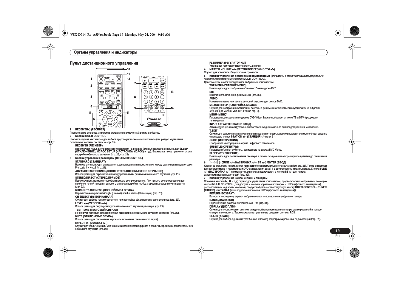
Пульт дистанционного управления
1
RECEIVER (РЕСИВЕР)
Переключение ресивера из режима ожидание во включенный режим и обратно.
2
Кнопки MULTI CONTROL
Нажмите одну из этих кнопок для выбора другого управляемого компонента (см. раздел
Управление
остальными частями системы на стр. 35).
RECEIVER (РЕСИВЕР)
Переключает пульт дистанционного управления на ресивер (для выбора таких режимов, как
SLEEP
(ОТКЛЮЧЕНИЕ), MCACC SETUP (НАСТРОЙКА MCACC) и т.д.). Эта кнопка также применяется для
настройки объемного звучания (стр. 25, стр. 28).
3
Кнопки управления ресивером (RECEIVER CONTROL)
STANDARD (СТАНДАРТ)
Нажмите эту кнопку для стандартного декодирования и переключения между различными параметрами
Pro Logic II и Neo:6 (стр. 21).
ADVANCED SURROUND (ДОПОЛНИТЕЛЬНОЕ ОБЪЕМНОЕ ЗВУЧАНИЕ)
Используется для переключения между различными режимами объемного звучания (стр. 21).
STEREO/DIRECT (СТЕРЕО/ПРЯМОЕ)
Переключатель прямого/стереофонического воспроизведения. При прямом воспроизведении для
наиболее точной передачи входного сигнала настройки тембра и уровня каналов не учитываются
(стр. 22).
MIDNIGHT/LOUDNESS (НОЧНОЙ/СИЛА ЗВУКА)
Переключение в режим Midnight (Ночной) или Loudness (Сила звука) (стр. 23).
CH SELECT (ВЫБОР КАНАЛА)
Служит для выбора громкоговорителя при настройке объемного звучания ресивера (стр. 29).
LEVEL +/– (УРОВЕНЬ +/–)
Используется для регулировки уровней объемного звучания ресивера (стр. 29).
TEST TONE (ТЕСТОВЫЙ СИГНАЛ)
Генерирует тестовый звуковой сигнал при настройке объемного звучания ресивера (стр. 29).
MUTE (ОТКЛЮЧЕНИЕ ЗВУКА)
Используется для отключения звука (или включения отключенного звука).
EFFECT +/– (ЭФФЕКТ +/–)
Служит для увеличения или уменьшения интенсивности эффекта в различных режимах дополнительного
объемного звучания (стр. 21).
FL DIMMER (РЕГУЛЯТОР ФЛ)
Уменьшает или увеличивает яркость дисплея.
4
MASTER VOLUME +/– (РЕГУЛЯТОР ГРОМКОСТИ +/–)
Служит для установки общего уровня громкости.
5
Кнопки управления ресивером и компонентами (для работы с этими кнопками предварительно
нажмите соответствующую кнопку
MULTI CONTROL).
Действие этих кнопок определяется выбранным компонентом.
TOP MENU (ГЛАВНОЕ МЕНЮ)
Используется для отображения “главного” меню диска DVD.
SR+
Включение/выключение режима SR+ (стр. 30).
AUDIO
Изменение языка или канала звуковой дорожки для дисков DVD.
MCACC SETUP (НАСТРОЙКА MCACC)
Служит для настройки акустической системы в режиме многоканальной акустической калибровки
(стр. 28, для модели VSX-D814 также стр. 9).
MENU (МЕНЮ)
Показывает дисковое меню дисков DVD-Video. Также отображается меню ТВ и DTV (цифрового
телевидения).
INPUT ATT (АТТЕНЮАТОР ВХОД)
Аттенюирует (понижает) уровень аналогового входного сигнала для предотвращения искажений.
T.EDIT
Служит для запоминания и присваивания названия станции, которую впоследствии можно будет вызвать
с помощью кнопок
STATION +/– (СТАНЦИЯ +/–) (стр. 31).
GUIDE (ИНСТРУКЦИИ)
Отображает инструкции на экране цифрового телевизора.
SUBTITLE (СУБТИТРЫ)
Показывает/меняет субтитры, записанные на дисках DVD-Video.
SLEEP (ОТКЛЮЧЕНИЕ)
Используется для переключения ресивера в режим ожидания и выбора периода времени до отключения
ресивера.
6
(TUNE +/– (НАСТРОЙКА +/–), ST +/–) /ENTER (ВВОД)
Кнопки со стрелками используются при настройке системы объемного звучания (см. стр. 25). Также они служат
для работы с меню и параметрами DVD и управления декой 1 в двухкассетном проигрывателе. Кнопки
TUNE
+/– (НАСТРОЙКА +/–) применяются для поиска радиочастот, а кнопки ST +/– для поиска
запрограммированных станций (стр. 32).
7
Кнопки управления компонентами и тюнером
Основные кнопки ( , и т.д.) служат для управления компонентом, предварительно выбранным с помощью
кнопок
MULTI CONTROL. Для доступа к кнопкам управления тюнером и DTV (цифрового телевидения),
расположенным над этими кнопками, следует выбрать соответствующую кнопку
MULTI CONTROL — TUNER
(ТЮНЕР) или TV/SAT (если подключен приемник DTV (цифрового телевидения)).
RETURN (ВОЗВРАТ)
Возврат к последнему экрану, выбранному при использовании цифрового тюнера.
BAND (ДИАПАЗОН)
Переключение диапазонов тюнера AM — FM (стр. 31).
DISPLAY (ДИСПЛЕЙ)
Служит для переключения дисплея между отображением названия запрограммированной в тюнере
станции и ее частоты. Также показывает различные сведения системы RDS.
CLASS (КЛАСС)
Служит для выбора одного из трех банков (классов) запрограммированных радиостанций (стр. 31).
SOURCE
MULTI CONTROL
RECEIVER
INPUT SELECT
STEREO/
DIRECT
MIDNIGHT/
LOUDNESS
ADVANCED
SURROUND
LEVEL
EFFECT
RECEIVER CONTROL
CH
SELECT
STANDARD
MUTE
TOP MENU
SR+
MENU
SETUP
AUDIO
INPUT ATT
T.EDIT
GUIDE
SUBTITLE
MCACC
SETUP
SLEEP
TEST
TONE
FL
DIMMER
ST
TUNE
MASTER
VOLUME
ST
TUNE
DVD/LD
ENTER
TV / SAT
C D
VCR/DVR
TV CONT
TUNER
CD-R/TAPE
RECEIVER
1
2
3
4
5
6
10
11
12
5
BAND
RETURN
A
E
D
C
B
DISC
DISPLAY
CLASS
MPX
D.ACCESS
TV CONTROL
SETUP
SLEEP
CHANNEL
VOLUME
INPUT
SELECT
+10
RECEIVER
CHANNEL
ENTER
1
2
3
4
5
6
7
8
9
0
7
8
13
14
9
VSX-D714_Ru_A5New.book Page 19 Monday, May 24, 2004 9:10 AM
Органы управления и индикаторы
20
Ru
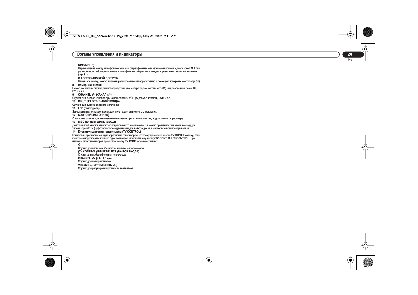
MPX (МОНО)
Переключение между монофоническим или стереофоническим режимами приема в диапазоне FM. Если
радиосигнал слаб, переключение в монофонический режим приведет к улучшению качества звучания
(стр. 31).
D.ACCESS (ПРЯМОЙ ДОСТУП)
Нажав эту кнопку, можно вызвать радиостанцию непосредственно с помощью номерных кнопок (стр. 31).
8
Номерные кнопки
Номерные кнопки служат для непосредственного выбора радиочастоты (стр. 31) или дорожки на диске CD,
DVD, и т.д.
9
CHANNEL +/– (КАНАЛ +/–)
Служат для выбора каналов при использовании VCR (видеомагнитофон), DVR и т.д.
10 INPUT SELECT (ВЫБОР ВХОДА)
Служит для выбора входного источника.
11 LED (светодиод)
Загорается при отправке команды с пульта дистанционного управления.
12 SOURCE (ИСТОЧНИК)
Эта кнопка служит для включения/выключения других компонентов, подключенных к ресиверу.
13 DISC (ENTER) (ДИСК (ВВОД))
Действие этой кнопки зависит от подключенного компонента. Ее можно применять для ввода команд для
телевизора и DTV (цифрового телевидения) или для выбора диска в многодисковом проигрывателе.
14 Кнопки управления телевизором (TV CONTROL)
Эти кнопки предназначены для управления телевизором, которому присвоена кнопка
TV CONT. Поэтому, если
к системе подключается только один телевизор, присвойте ему кнопку
TV CONT MULTI CONTROL. При
наличии двух телевизоров присвойте кнопку
TV CONT основному из них.
Служит для включения/выключения питания телевизора.
(TV CONTROL) INPUT SELECT (ВЫБОР ВХОДА)
Служит для выбора функции телевизора.
CHANNEL +/– (КАНАЛ +/–)
Служит для выбора каналов.
VOLUME +/– (ГРОМКОСТЬ +/–)
Служит для регулировки громкости телевизора.
VSX-D714_Ru_A5New.book Page 20 Monday, May 24, 2004 9:10 AM
08:08
никогда не перегревайте ресивер Pioneer VSX — D514, иначе…
14:25
Ресивер в качестве стереоусилителя: обзор на примере Pioneer VSX-416
05:27
Ремонт pioneer vsx-D714
05:07
Pioneer vsx-d814-s Audio/video multi-channel receiver
02:21
Pioneer VSX-D814-S Próba
06:11
Quick internal view of the Pioneer VSX D814 audo video amplifier
10:49
PIONEER VSX-D814 & SAMSUNG DVD-HD950
Нажмите на кнопку для помощи
Pioneer VSX-D814
AUDIO/VIDEO MULTI-CHANNEL
RECEIVER
VSX-D514
VSX-D714
Operating Instructions
VSX_514-814.fm 1 ページ 2004年3月2日 火曜日 午後8時35分
Manual
View the manual for the Pioneer VSX-D814 here, for free. This manual comes under the category receivers and has been rated by 13 people with an average of a 8.8.
This manual is available in the following languages: English. Do you have a question about the Pioneer VSX-D814 or do you need help?
Ask your question here
Index
- 01 Before you startChecking what’s in the box . . . . . . . . . . . . 5
- Making cable connections . . . . . . . . . . . . . 5
- Loading the batteries . . . . . . . . . . . . . . . . . 5
- Operating range of remote control unit . . . 6
- 02 5 minute guideIntroduction to home theater . . . . . . . . . . . 7
- Listening to Surround Sound . . . . . . . . . . . 8
- Using the Quick Setup . . . . . . . . . . . . . . . 12
- 03 Connecting upAudio/Video cords . . . . . . . . . . . . . . . . . . 14
- S-video cables . . . . . . . . . . . . . . . . . . . . . 14
- Component video cords . . . . . . . . . . . . . . 14
- Digital audio coaxial cords/Opticalcables . . . . . . . . . . . . . . . . . . . . . . . . . . . 14
- Connecting digital components . . . . . . . . 15
- Connecting audio components . . . . . . . . 16
- Connecting DVD 5.1 channelcomponents . . . . . . . . . . . . . . . . . . . . . . . 17
- Connecting video components. . . . . . . . . 18
- Connecting antennas . . . . . . . . . . . . . . . . 19
- Connecting the speakers(VSX-D514/D714) . . . . . . . . . . . . . . . . . . . 20
- Connecting the speakers (VSX-D814) . . . . 21
- Connecting additional amplifiers . . . . . . . 24
- Operating other Pioneer components . . . 25
- Using this receiver with a Pioneerplasma display . . . . . . . . . . . . . . . . . . . . . 26
- 04 Controls and displaysFront panel (VSX-D514) . . . . . . . . . . . . . . . 27
- Front panel (VSX-D714/D814) . . . . . . . . . . 29
- Display . . . . . . . . . . . . . . . . . . . . . . . . . . . 31
- Remote control . . . . . . . . . . . . . . . . . . . . . 32
- 05 Listening to your systemListening in surround sound . . . . . . . . . . . 36
- Listening in stereo . . . . . . . . . . . . . . . . . . . 38
- Choosing the input signal . . . . . . . . . . . . . 38
- Using the Surround Back Channel(SB CH) . . . . . . . . . . . . . . . . . . . . . . . . . . . 39
- Using the Virtual Surround Back mode(VSB) . . . . . . . . . . . . . . . . . . . . . . . . . . . . . 40
- Using Midnight and Loudness listening . .41
- Using the tone controls . . . . . . . . . . . . . . . 41
- Playing other sources . . . . . . . . . . . . . . . . 42
- Selecting the multichannel analoginputs . . . . . . . . . . . . . . . . . . . . . . . . . . . . 42
- Using the sleep timer . . . . . . . . . . . . . . . . 43
- 06 Setting up the receiverChoosing your receiver setup . . . . . . . . . . 44
- Dynamic range control setting. . . . . . . . 50
- Dual mono setting . . . . . . . . . . . . . . . . . 50
- Component video input settings . . . . . . 50
- Digital input settings . . . . . . . . . . . . . . . 50
- SR+ control for Pioneer plasmadisplays . . . . . . . . . . . . . . . . . . . . . . . . . 51
- Using the SR+ mode with a Pioneerplasma display . . . . . . . . . . . . . . . . . . . . . 54
- 07 Using the tunerListening to the radio . . . . . . . . . . . . . . . . 56
- Improving FM stereo sound . . . . . . . . . . 56
- Tuning directly to a station. . . . . . . . . . . 56
- Naming station presets . . . . . . . . . . . . . 58
- Listening to station presets . . . . . . . . . . 58
- Changing the frequency step . . . . . . . . . . 58
- 08 Making recordingsMaking an audio or a video recording . . . 59
- 09 Controlling the rest of yoursystemSetting the remote to control othercomponents . . . . . . . . . . . . . . . . . . . . . . . 60
- Preset Code List (VSX-D514/D714) . . . . . . . 66
- Preset Code List (VSX-D814) . . . . . . . . . . . 68
- 10 Additional informationTroubleshooting . . . . . . . . . . . . . . . . . . . . 70
- Resetting the main unit . . . . . . . . . . . . . . . 72
- Switching the speaker impedance. . . . . . . 72
- Specifications . . . . . . . . . . . . . . . . . . . . . . 73
Product Images (1)
Pioneer VSX-D814 specifications
Below you will find the product specifications and the manual specifications of the Pioneer VSX-D814.
The Pioneer VSX-D814 is a receiver that offers a range of audio features and functionalities. Designed with precision and attention to detail, this receiver is capable of delivering high-quality sound for an immersive audio experience.
Equipped with advanced audio processing technology, the Pioneer VSX-D814 enhances audio signals to provide clear and crisp sound output. It supports various audio formats, ensuring compatibility with a wide range of devices and media sources. The receiver also features multiple audio inputs and outputs, allowing for seamless connectivity with external devices.
With its built-in amplifier, the Pioneer VSX-D814 is capable of driving speakers with sufficient power, ensuring optimal performance. The receiver supports multiple speaker configurations, providing flexibility for creating customized sound setups.
The Pioneer VSX-D814 is designed with user convenience in mind. It features a user-friendly interface and intuitive controls, allowing for easy navigation and operation. The receiver also comes with a remote control, enabling convenient operation from a distance.
In terms of design and build quality, the Pioneer VSX-D814 is crafted using premium materials, ensuring durability and longevity. Its sleek and compact design makes it a suitable addition to any home entertainment setup.
Overall, the Pioneer VSX-D814 is a reliable and versatile receiver that offers high-quality audio performance and user-friendly features. Whether you are a casual listener or an avid audiophile, this receiver is designed to meet your audio needs.
General
| Brand | Pioneer |
| Model | VSX-D814 |
| Product | receiver |
| Language | English |
| Filetype | User manual (PDF) |
Frequently Asked Questions
Can’t find the answer to your question in the manual? You may find the answer to your question in the FAQs about the Pioneer VSX-D814 below.
How can I set up the speakers properly with the Pioneer VSX-D814?
To set up the speakers, first, ensure they are positioned correctly according to the room’s layout and the recommended speaker placement guidelines. Then, access the «Speaker Setup» menu on the receiver, where you can configure the speaker size, distance, and level settings to optimize the audio output for each individual speaker.
How can I connect my devices to the Pioneer VSX-D814 receiver?
To connect your devices, locate the corresponding input jacks on the back of the receiver and use the appropriate cables to establish the connections. Ensure that each device is connected to its respective input to enjoy optimal audio and video performance.
How do I adjust the sound settings on the Pioneer VSX-D814?
To adjust the sound settings, press the «Audio Parameter» button on the front panel or remote control. Navigate through the menu options to customize various aspects such as equalization, surround sound effects, and speaker settings to suit your preference.
How do I program the remote control for multiple devices?
To program your remote control, press and hold the «Receiver» mode button for about three seconds until the corresponding indicator on the remote’s display starts blinking. Then, follow the instructions in the receiver’s manual for entering the appropriate codes or using the auto-programming feature to synchronize the remote with your desired devices.
How can I troubleshoot common issues with the Pioneer VSX-D814?
For common issues like audio distortion, connectivity problems, or error messages, try resetting the receiver by unplugging it from the power source for a few minutes and then plugging it back in. If the problem persists, consult the troubleshooting section of the manual for specific instructions or contact Pioneer customer support for further assistance.
Can bluetooth devices of different brands be connected to each other?
Yes, bluetooth is a universal method that allows different devices equipped with bluetooth to connect to each other.
What is bluetooth?
Bluetooth is a way of exchanging data wirelessly between electronic devices via radio waves. The distance between the two devices that exchange data can in most cases be no more than ten metres.
What is HDMI?
HDMI stands for High-Definition Multimedia Interface. An HDMI cable is used to transport audio and video signals between devices.
When is my volume too loud?
A volume above 80 decibels can be harmful to hearing. When the volume exceeds 120 decibels, direct damage can even occur. The chance of hearing damage depends on the listening frequency and duration.
How can I best clean my receiver?
A slightly damp cleaning cloth or soft, dust-free cloth works best to remove fingerprints. Dust in hard-to-reach places is best removed with compressed air.
Wat is Dolby Atmos?
Dolby Atmos is a technology that ensures that the sound is reflected from the ceiling to where you are listening. This makes it possible to create a 5.1 effect with only 1 speaker.
Is the manual of the Pioneer VSX-D814 available in English?
Yes, the manual of the Pioneer VSX-D814 is available in English .
Is your question not listed? Ask your question here
AUDIO/VIDEO MULTI-CHANNEL
RECEIVER
VSX-D814
VSX-D914
Operating Instructions
Thank you for buying this Pioneer product.
Please read through these operating instructions
so you will know how to operate your model
properly. After you have finished reading the
instructions, put them away in a safe place for future
reference.
CAUTION – PREVENT ELECTRIC SHOCK DO
NOT USE THIS (POLARIZED) PLUG
WITH AN EXTENSION CORD.
RECEPTACLE OR OTHER OUTLET
UNLESS THE BLADES CAN BE
FULLY INSERTED TO PREVENT
BLADE EXPOSURE.
If the socket outlets on the associated equipment
are not suitable for the plug supplied with the
product, the plug must be removed and appropriate
one fitted. Replacement and mounting of an AC plug
on the power supply cord of this unit should be
perfomed only by qualified service personnel. The
cut-off plug must be disposed of as an electrical
shock hazard could exist if connected to a socket
outlet.
D3-4-2-2-1a_En
WARNING – TO PREVENT FIRE OR SHOCK
HAZARD, DO NOT EXPOSE THIS
APPLIANCE TO RAIN OR MOISTURE.
D1-4-2-1_En
ATTENTION –
WARNING: Handling the cord on this product or
cords associated with accessories sold with the
product will expose you to lead, a chemical known to
the State of California and other governmental
entities to cause cancer and birth defects or other
POUR PREVENIR LES CHOCS
ELECTRIQUES NE PAS UTILISER
CETTE FICHE POLARISEE AVEC UN
PROLONGATEUR UNE PRISE DE
COURANT OU UNE AUTRE SORTIE
DE COURANT, SAUF SI LES LAMES
PEUVENT ETRE INSEREES A FOND
SANS EN LAISSER AUCUNE PARTIE
A DECOUVVERT.
D2-4-4-1_EF
reproductive harm.
Wash hands after handling
D36-P4_En
IMPORTANT NOTICE – THE SERIAL NUMBER FOR THIS EQUIPMENT IS LOCATED IN THE REAR.
PLEASE WRITE THIS SERIAL NUMBER ON YOUR ENCLOSED WARRANTY CARD AND
KEEP IN A SECURE AREA. THIS IS FOR YOUR SECURITY.
D1-4-2-6-1_En
NOTE: This equipment has been tested and found to comply with the limits for a Class B digital device, pursuant to
Part 15 of the FCC Rules. These limits are designed to provide reasonable protection against harmful interference in
a residential installation. This equipment generates, uses, and can radiate radio frequency energy and, if not
installed and used in accordance with the instructions, may cause harmful interference to radio communications.
However, there is no guarantee that interference will not occur in a particular installation. If this equipment does
cause harmful interference to radio or television reception, which can be determined by turning the equipment off
and on, the user is encouraged to try to correct the interference by one or more of the following measures:
– Reorient or relocate the receiving antenna.
– Increase the separation between the equipment and receiver.
– Connect the equipment into an outlet on a circuit different from that to which the receiver is connected.
– Consult the dealer or an experienced radio/TV technician for help.
D8-10-1-2_En
This Class B digital apparatus complies with Canadian ICES-003.
Cet appareil numérique de la Classe B est conforme à la norme NMB-003 du Canada.
D8-10-1-3_EF
Information to User
Alteration or modifications carried out without appropriate authorization may invalidate the user’s right to operate
the equipment.
D8-10-2_En
CAUTION: This product satisfies FCC regulations when shielded cables and connectors are used to connect the
unit to other equipment. To prevent electromagnetic interference with electric appliances such as radios and
televisions, use shielded cables and connectors for connections.
Manufactured under license from Dolby
For U.S. and Australia Model
D8-10-3a_En
Laboratories. «Dolby», «Pro Logic»,
«Surround EX», and the double-D symbol
are trademarks of Dolby Laboratories.
«DTS» ,»DTS-ES Extended Surround» and
«Neo:6» are trademarks of Digital Theater
Systems, Inc.
C67-7-3_En
The lightning flash with arrowhead, within
an equilateral triangle, is intended to alert
the user to the presence of uninsulated
«dangerous voltage» within the product’s
enclosure that may be of sufficient
magnitude to constitute a risk of electric
shock to persons.
CAUTION
RISK OF ELECTRIC SHOCK
DO NOT OPEN
CAUTION:
TO PREVENT THE RISK OF ELECTRIC
SHOCK, DO NOT REMOVE COVER (OR
BACK). NO USER-SERVICEABLE PARTS
INSIDE. REFER SERVICING TO QUALIFIED
SERVICE PERSONNEL.
The exclamation point within an equilateral
triangle is intended to alert the user to the
presence of important operating and
maintenance (servicing) instructions in the
literature accompanying the appliance.
D1-4-2-3_En
READ INSTRUCTIONS — All the safety and
operating instructions should be read before the
product is operated.
RETAIN INSTRUCTIONS — The safety and
operating instructions should be retained for
future reference.
HEED WARNINGS — All warnings on the product
and in the operating instructions should be
adhered to.
FOLLOW INSTRUCTIONS — All operating and use
instructions should be followed.
CLEANING — The product should be cleaned only
with a polishing cloth or a soft dry cloth. Never
clean with furniture wax, benzine, insecticides
or other volatile liquids since they may corrode
the cabinet.
ATTA CHMENTS — Do not use attachments not
recommended by the product manufacturer as
they may cause hazards.
WATER AND MOISTURE — Do not use this
product near water — for example, near a
bathtub, wash bowl, kitchen sink, or laundry
tub; in a wet basement; or near a swimming
pool; and the like.
ACCESSORIES — Do not place this product on an
unstable cart, stand, tripod, bracket, or table.
The product may fall, causing serious injury to a
child or adult, and serious damage to the
product. Use only with a cart, stand, tripod,
bracket, or table recommended by the
manufacturer, or sold with the product. Any
mounting of the product should follow the
manufacturer’s instructions, and should use a
mounting accessory recommended by the
manufacturer.
CART — A product and cart combination should be
moved with care. Quick stops, excessive force,
and uneven surfaces may cause the product
and cart combination to overturn.
VENTILATION — Slots and openings in the cabinet
are provided for ventilation and to ensure
reliable operation of the product and to protect
it from overheating, and these openings must
not be blocked or covered. The openings should
never be blocked by placing the product on a
bed, sofa, rug, or other similar surface. This
product should not be placed in a built-in
installation such as a bookcase or rack unless
proper ventilation is provided or the
manufacturer’s instructions have been adhered
to.
POWER SOURCES — This product should be
operated only from the type of power source
indicated on the marking label. If you are not
sure of the type of power supply to your home,
consult your product dealer or local power
company.
LOCATION – The appliance should be installed in a
stable location.
NONUSE PERIODS – The power cord of the
appliance should be unplugged from the outlet
when left un-used for a long period of time.
GROUNDING OR POLARIZATION
• If this product is equipped with a polarized
alternating current line plug (a plug having one
blade wider than the other), it will fit into the
outlet only one way. This is a safety feature. If
you are unable to insert the plug fully into the
outlet, try reversing the plug. If the plug should
still fail to fit, contact your electrician to replace
your obsolete outlet. Do not defeat the safety
purpose of the polarized plug.
• If this product is equipped with a three-wire
grounding type plug, a plug having a third
(grounding) pin, it will only fit into a grounding
type power outlet. This is a safety feature. If you
are unable to insert the plug into the outlet,
contact your electrician to replace your obsolete
outlet. Do not defeat the safety purpose of the
grounding type plug.
POWER-CORD PROTECTION — Power-supply
cords should be routed so that they are not likely
to be walked on or pinched by items placed
upon or against them, paying particular
attention to cords at plugs, convenience
receptacles, and the point where they exit from
the product.
OUTDOOR ANTENNA GROUNDING — If an
outside antenna or cable system is connected to
the product, be sure the antenna or cable
system is grounded so as to provide some
protection against voltage surges and built-up
static charges. Article 810 of the National
Electrical Code, ANSI/NFPA 70, provides
information with regard to proper grounding of
the mast and supporting structure, grounding of
the lead-in wire to an antenna discharge unit,
size of grounding conductors, location of
antenna-discharge unit, connection to
grounding electrodes, and requirements for the
grounding electrode. See Figure A.
LIGHTNING — For added protection for this
product during a lightning storm, or when it is
left unattended and unused for long periods of
time, unplug it from the wall outlet and
disconnect the antenna or cable system. This
will prevent damage to the product due to
lightning and power-line surges.
POWER LINES — An outside antenna system
should not be located in the vicinity of overhead
power lines or other electric light or power
circuits, or where it can fall into such power
lines or circuits. When installing an outside
antenna system, extreme care should be taken
to keep from touching such power lines or
circuits as contact with them might be fatal.
OVERLOADING — Do not overload wall outlets,
extension cords, or integral convenience
receptacles as this can result in a risk of fire or
electric shock.
ELECTRIC
SERVICE
EQUIPMENT
Fig. A
OBJECT AND LIQUID ENTRY — Never push
objects of any kind into this product through
openings as they may touch dangerous voltage
points or short-out parts that could result in a
fire or electric shock. Never spill liquid of any
kind on the product.
SERVICING — Do not attempt to service this
product yourself as opening or removing covers
may expose you to dangerous voltage or other
hazards. Refer all servicing to qualified service
personnel.
DAMAGE REQUIRING SERVICE — Unplug this
product from the wall outlet and refer servicing
to qualified service personnel under the
following conditions:
• When the power-supply cord or plug is
damaged.
• If liquid has been spilled, or objects have fallen
into the product.
• If the product has been exposed to rain or water.
• If the product does not operate normally by
following the operating instructions. Adjust only
those controls that are covered by the operating
instructions as an improper adjustment of other
controls may result in damage and will often
require extensive work by a qualified technician
to restore the product to its normal operation.
• If the product has been dropped or damaged in
any way.
• When the product exhibits a distinct change in
performance — this indicates a need for service.
REPLACEMENT PARTS — When replacement parts
are required, be sure the service technician has
used replacement parts specified by the
manufacturer or have the same characteristics
as the original part. Unauthorized substitutions
may result in fire, electric shock, or other
hazards.
SAFETY CHECK — Upon completion of any service
or repairs to this product, ask the service
technician to perform safety checks to
determine that the product is in proper
operating condition.
WALL OR CEILING MOUNTING — The product
should not be mounted to a wall or ceiling.
HEAT — The product should be situated away from
heat sources such as radiators, heat registers,
stoves, or other products (including amplifiers)
that produce heat.
ANTENNA
LEAD IN
GROUND
CLAMP
WIRE
ANTENNA
DISCHARGE UNIT
(NEC SECTION 810-20)
GROUNDING CONDUCTORS
(NEC SECTION 810-21)
GROUND CLAMPS
POWER SERVICE GROUNDING
ELECTRODE SYSTEM
(NEC ART 250, PART H)
NEC — NATIONAL ELECTRICAL CODE
D1-4-2-2_En

Contents
01 Before you start
Checking what’s in the box. . . . . . . . . . . . . . 6
Installing the receiver . . . . . . . . . . . . . . . . . . 6
Making cable connections . . . . . . . . . . . . . . 6
Loading the batteries. . . . . . . . . . . . . . . . . . . 6
Operating range of remote control unit. . . . 7
02 5 minute guide
Introduction to home theater . . . . . . . . . . . . 8
Listening to Surround Sound . . . . . . . . . . . . 9
Using the Quick Setup . . . . . . . . . . . . . . . . 12
03 Quick surround sound setup
Automatically calibrating your listening
area (MCACC) . . . . . . . . . . . . . . . . . . . . . . . 14
04 Connecting up
Audio/Video cords . . . . . . . . . . . . . . . . . . . . 16
S-video cables . . . . . . . . . . . . . . . . . . . . . . . 16
Component video cords . . . . . . . . . . . . . . . 16
Digital audio coaxial cords/
Optical cables . . . . . . . . . . . . . . . . . . . . . . . 16
Connecting digital components . . . . . . . . . 17
Connecting audio components . . . . . . . . . 18
Connecting DVD 5.1 channel
components . . . . . . . . . . . . . . . . . . . . . . . . . 18
Connecting video components. . . . . . . . . . 19
Connecting to the front panel
video terminal . . . . . . . . . . . . . . . . . . . . . . 19
Connecting antennas . . . . . . . . . . . . . . . . . 20
FM wire antenna . . . . . . . . . . . . . . . . . . . . 20
AM loop antenna. . . . . . . . . . . . . . . . . . . . 20
Using external antennas . . . . . . . . . . . . . 20
Connecting the speakers . . . . . . . . . . . . . . 21
Speaker terminals . . . . . . . . . . . . . . . . . . . 22
A and B speaker systems . . . . . . . . . . . . . 22
Hints on speaker placement . . . . . . . . . . 22
Connecting additional amplifiers . . . . . . . . 24
AC outlet . . . . . . . . . . . . . . . . . . . . . . . . . . . . 25
Operating other Pioneer components . . . . 25
Using this receiver with a Pioneer
plasma display . . . . . . . . . . . . . . . . . . . . . . . 26
05 Controls and displays
Front panel . . . . . . . . . . . . . . . . . . . . . . . . . . 27
Display . . . . . . . . . . . . . . . . . . . . . . . . . . . . . 29
Remote control. . . . . . . . . . . . . . . . . . . . . . . 31
06 Listening to your system
Listening in surround sound. . . . . . . . . . . . 35
Using the Advanced surround effects. . . 35
Listening in stereo . . . . . . . . . . . . . . . . . . . . 36
Choosing the input signal . . . . . . . . . . . . . . 37
Using the Surround Back Channel
(SB CH) . . . . . . . . . . . . . . . . . . . . . . . . . . . . . 38
Using the Virtual Surround Back
mode (VSB). . . . . . . . . . . . . . . . . . . . . . . . . . 39
Using Loudness and Midnight listening . . 40
Using the tone controls . . . . . . . . . . . . . . . . 40
Playing other sources . . . . . . . . . . . . . . . . . 40
Selecting the multi-channel analog
inputs . . . . . . . . . . . . . . . . . . . . . . . . . . . . . . 41
Using the sleep timer . . . . . . . . . . . . . . . . . 41
07 Setting up the receiver
Choosing your receiver setup . . . . . . . . . . . 42
Speaker setting . . . . . . . . . . . . . . . . . . . . . 43
Surround back speaker setting . . . . . . . . 44
Subwoofer setting . . . . . . . . . . . . . . . . . . . 44
Crossover frequency setting. . . . . . . . . . . 44
LFE attenuator setting. . . . . . . . . . . . . . . . 45
Front left speaker distance setting . . . . . 45
Center speaker distance setting . . . . . . . 45
Front right speaker distance setting . . . . 46
Surround right speaker distance
setting. . . . . . . . . . . . . . . . . . . . . . . . . . . . . 46
Surround back speaker distance
setting. . . . . . . . . . . . . . . . . . . . . . . . . . . . . 46

Surround left speaker distance setting . . 46
Subwoofer distance setting . . . . . . . . . . . 46
Dynamic range control setting. . . . . . . . . 47
Dual mono setting . . . . . . . . . . . . . . . . . . . 47
Component video input settings . . . . . . . 47
Digital input settings . . . . . . . . . . . . . . . . . 47
SR+ control for Pioneer plasma
displays. . . . . . . . . . . . . . . . . . . . . . . . . . . . 48
Manually calibrating your listening
area (MCACC). . . . . . . . . . . . . . . . . . . . . . . . 49
Setting separate channel levels for
listening modes . . . . . . . . . . . . . . . . . . . . . . 50
Using the SR+ mode with a Pioneer
plasma display . . . . . . . . . . . . . . . . . . . . . . . 51
08 Using the tuner
Listening to the radio . . . . . . . . . . . . . . . . . . 53
Improving FM stereo sound . . . . . . . . . . . 53
Tuning directly to a station . . . . . . . . . . . . 53
Saving station presets . . . . . . . . . . . . . . . . . 54
Naming station presets. . . . . . . . . . . . . . . 54
Listening to station presets. . . . . . . . . . . . 55
09 Making recordings
Making an audio or a video recording . . . . 56
10 Controlling the rest of your
system
Setting the remote to control other
components . . . . . . . . . . . . . . . . . . . . . . . . . 57
Selecting preset codes directly . . . . . . . . . . 57
Programming signals from other
remote controls. . . . . . . . . . . . . . . . . . . . . . . 58
Erasing one of the remote control
button settings . . . . . . . . . . . . . . . . . . . . . . . 59
Erasing all of the remote control
presets . . . . . . . . . . . . . . . . . . . . . . . . . . . . . . 60
Direct function . . . . . . . . . . . . . . . . . . . . . . . 60
Confirming preset codes . . . . . . . . . . . . . . . 60
Controls for TVs. . . . . . . . . . . . . . . . . . . . . . . 61
Controls for other components . . . . . . . . . . 62
11 Additional information
Troubleshooting . . . . . . . . . . . . . . . . . . . . . . 65
Resetting the main unit . . . . . . . . . . . . . . . . 67
Switching the speaker impedance . . . . . . . 67
Specifications . . . . . . . . . . . . . . . . . . . . . . . . 68
Cleaning the unit . . . . . . . . . . . . . . . . . . . . . 69
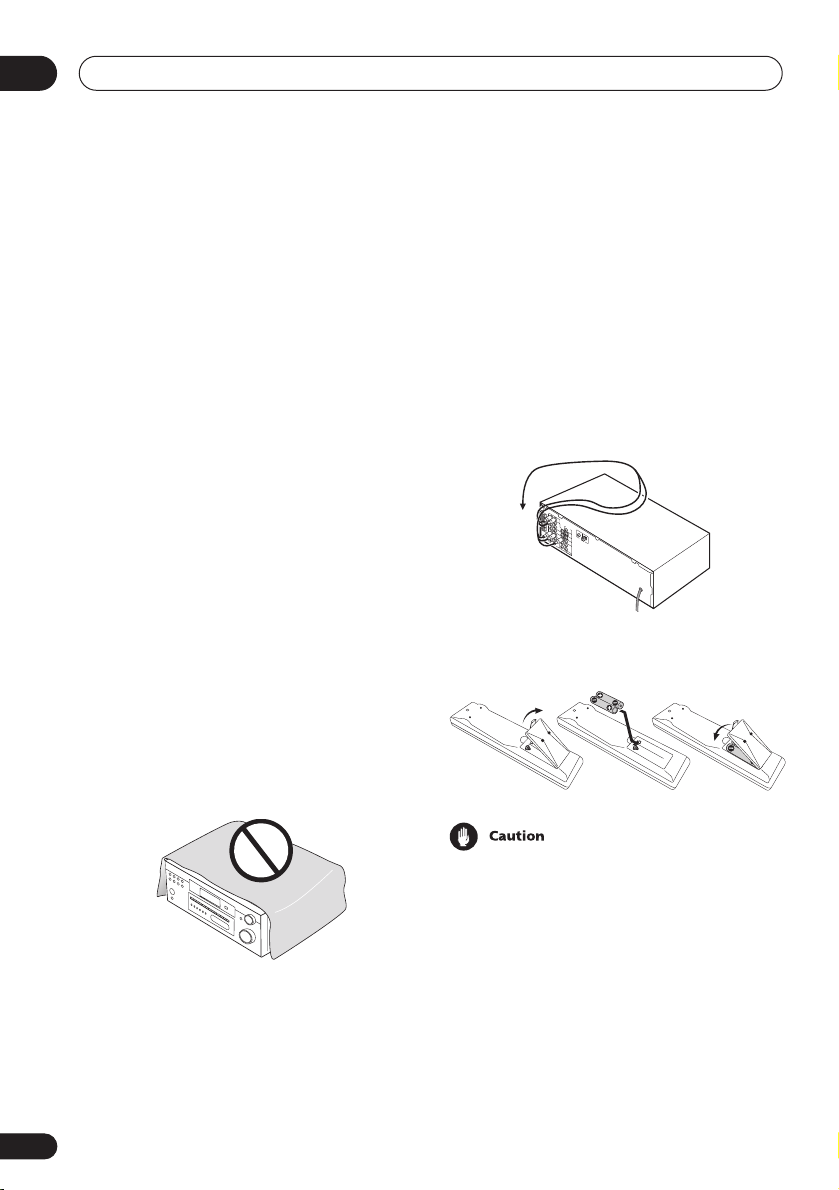
01
Before you start
Chapter 1:
Before you start
Checking what’s in the box
Please check that you’ve received the
following supplied accessories:
• AM loop antenna
• FM wire antenna
• AA/LR6 dry cell batteries x2
• Remote control
• These operating instructions
•
Warranty Card
VSX-D914 model only:
• Microphone
• Microphone stand
Installing the receiver
Please note the following points:
• Do not place objects directly on top of this
unit. This prevents proper heat dispersal.
• When installing on a rack, shelf, etc., be
sure to leave more than 8 inches (20 cm.)
of space above the receiver.
Making cable connections
Make sure not to bend the cables over the top
of this unit (as shown in the illustration). If this
happens, the magnetic field produced by the
transformers in this unit may cause a
humming noise from the speakers.
Loading the batteries
Incorrect use of batteries may result in such
hazards as leakage and bursting. Observe the
following precautions:
• Never use new and old batteries together.
• Insert the plus and minus sides of the
batteries properly according to the marks
in the battery case.
• Batteries with the same shape may have
different voltages. Do not use different
batteries together.
6
En
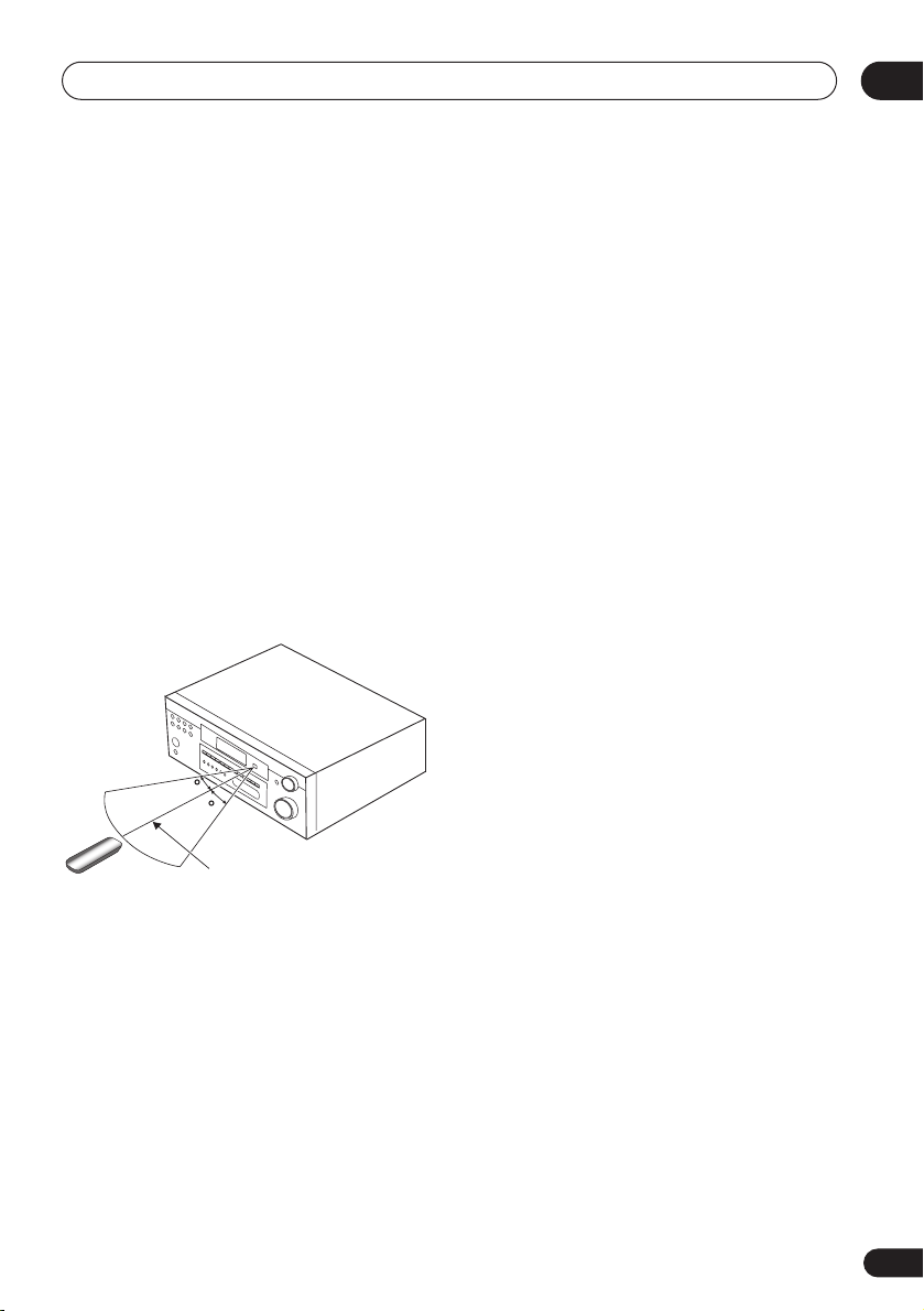
Before you start
• When disposing of used batteries, please
comply with governmental regulations or
environmental public instruction’s rules
that apply in your country or area.
Operating range of remote
control unit
The remote control may not work properly if:
• There are obstacles between the remote
control and the receiver’s remote sensor.
• Direct sunlight or fluorescent light is
shining onto the remote sensor.
• The receiver is located near a device that
is emitting infrared rays.
• The receiver is operated simultaneously
with another infrared remote control unit.
01
30
30
23ft (7m)
7
En

02
5 minute guide
Chapter 2:
5 minute guide
Introduction to home theater
You are probably used to using stereo equipment to listen to music, but may not be used to
home theater systems that give you many more options (such as surround sound) when
listening to soundtracks.
Home theater refers to the use of multiple audio tracks to create a surround sound effect,
making you feel like you’re in the middle of the action or concert. The surround sound you get
from a home theater system depends not only on the speakers you have set up in your room, but
also on the source and the sound settings of the receiver.
DVD-Video has become the basic source material for home theater due to its size, quality, and
ease of use. Depending on the DVD, you can have up to seven different audio tracks coming
from one disc, all of them being sent to different speakers in your system. This is what creates
a surround sound effect and gives you the feeling of ‘being there’.
This receiver will automatically decode Dolby Digital, DTS, or Dolby Surround DVD-Video discs,
according to your speaker setup. In most cases, you won’t have to make changes for realistic
surround sound, but other possibilities (like listening to a CD with multi-channel surround
sound) are explained in
Listening to your system
on page 35.
8
En
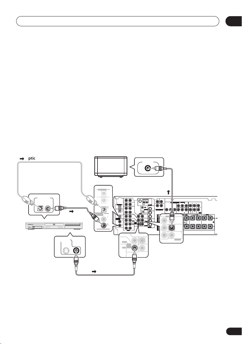
5 minute guide
Listening to Surround Sound
This receiver was designed with the easiest possible setup in mind, so with the following quick
setup guide, you should have your system hooked up for surround sound in no time at all. In
most cases, you can simply leave the receiver in the default settings.
Be sure to complete all connections before connecting this unit to the AC power source.
1 Hook up your DVD player.
For surround sound, you’ll want to hook up using a digital connection from the DVD player to
the receiver. You can do this with either a coaxial, or an optical connection (you don’t need to
connect both). If you hook up using an optical cable, you should refer to
on page 47 to assign the optical input to
DVD
.
Use a video cord to connect the video output on your DVD player to the receiver using the jacks
shown below.
2 Hook up your TV.
Use a video cord to connect your receiver to the TV using the jacks as shown below.
Digital input settings
02
Optical cable
DIGITAL OUT
STANDBY/ON
0
DVD player
TV
VIDEO IN
DIGITAL OUT
OPT
ASSIGNABLE
DIGITAL IN
OPT
2
(DVR/VCR)
OPT
1
(TV /
SA T)
COAX
2
(CD)
COAX
1
(DVD
/LD)
DIGITAL OUT
ASSIGNABLE
DIGITAL IN
(DVR/VCR)
AUX
IN
FM UNBAL
AM
Ω
75
LOOP
ANTENNA
CD
IN
OPT
OPT
OUT
2
IN
OPT
1
(TV/
IN
SAT)
COAX
2
IN
(CD)
COAX
1
OUT
(DVD
/LD)
IN
R
L
AUDIO
IN
DVD
/ LD
FRONT
D V D
5.1CH
INPUT
REC
IN
CD-R
/TAPE
/ MD
MONITOR OUT
OUT
CONTROL
DVR/
VCR
IN
VIDEO
IN
TV/
OUT
SAT
IN
DVD
MONITOR
/LD
OUT
FRONT
D V D
5.1CH
SUB
INPUT
REC
WOOFER
IN
CD-R
PREOUT
/ TAPE
/ MD
S-VIDEO
PLAY
Coaxial
cable
DVD PLAYER
Î
8
¡¢41
7
3
VIDEO OUT
S
Video cord
CEN-
SUB WOOFER
TER
COMPONENT VIDEO
MONITOR OUT
LR
SURROUND
DVD 5.1CH INPUT
BPRYPBPR
YP
OUT
DVR/
FRONT
RL R
VCR
S
VIDEO
IN
P
E
TV/
SAT
A
IN
A
K
DVD
/LD
E
IN
IN
R
S
ASSIGNABLE
LL
(
)
DVD/ LD
IN
¥
RR
(
)
TV / SAT
FRONT
IN
ø
SURROUND BACK
RL
OUT
SINGLE
SEE INSTRUCTION
MANUAL
MONITOR
OUT
SUB
WOOFER
PREOUT
SURROUND
BACK
CENTER
PREOUT
SURROUND
LR L
FRONTCENTER SURROUND
B
Video cord
9
En
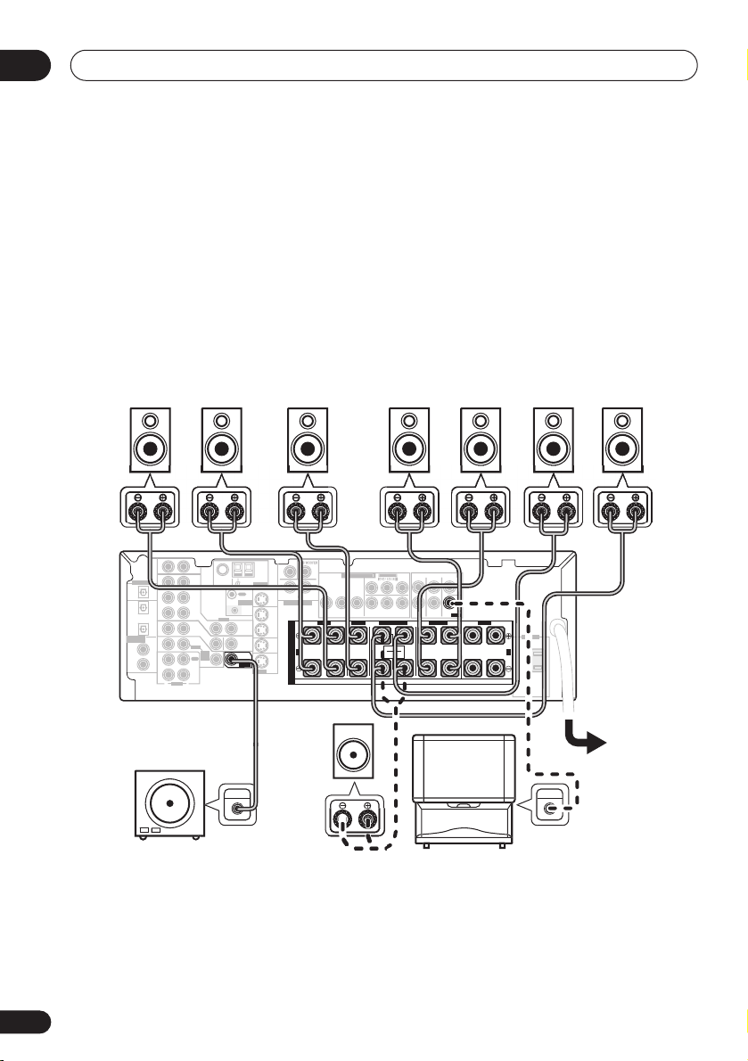
02
5 minute guide
3 Connect your speakers.
A complete setup of eight speakers (including the subwoofer) is shown here but everyone’s
home setup will vary. Simply connect the speakers you have in the manner shown below. The
receiver will work with just two stereo speakers (the front speakers in the diagram) but using at
least three speakers is recommended, and a complete setup is best.
Make sure you connect the speaker on the right to the right terminal and the speaker on the left
to the left terminal. Also make sure the positive and negative (
match those on the speakers. You can use speakers with a nominal impedance between 6–16
(please see
impedance of less than 8
Switching the speaker impedance
Ω
).
on page 67 if you plan to use speakers with an
+/–
) terminals on the receiver
Ω
Front speakers
Center speaker
Surround speakers
LR C LSRS
DIGITAL OUT
IN
OPT
OPT
OUT
2
(DVR/VCR)
IN
OPT
1
(TV/
IN
SAT)
ASSIGNABLE
COAX
DIGITAL IN
2
IN
(CD)
COAX
1
OUT
(DVD
/LD)
IN
Powered
AUX
75
Ω
CD
DVR/
VCR
VIDEO
IN
TV/
SAT
IN
DVD
/LD
FRONT
D V D
5.1CH
INPUT
REC
IN
CD-R
/ TAPE
/ MD
PLAY
R
L
AUDIO
OUT
CONTROL
OUT
MONITOR
OUT
SUB
WOOFER
PREOUT
LOOP
IN
ANTENNA
MONITOR OUT
OUT
DVR/
VCR
TV/
SAT
DVD
/LD
S-VIDEO
Passive
TE
MONITOR OUT
LR
SURROUND
DVD 5.1CH INPUT
IN
IN
IN
BPR
YP
FRONT
RL R
S
P
E
A
A
K
E
R
S
ASSIGNABL
YPBP
R
RR
(
)
TV / SAT
FRONT
SURROUND
IN
ø
SURROUND BACK
RL
SINGLE
SEE INSTRUCTION
MANUAL
CENTER
PREOUT
LR L
Surround back speakers
SBL SBR
FRONTCENTER SURROUND
AC OUTLET
B
subwoofer
or single
k
speake
• If you’re not using a subwoofer, change the front speaker setting (see
TV
UDIO I
Speaker setting
page 43) to large.
• To use the speaker on your TV as the center speaker (
C
), connect the
CENTER PREOUT
on this unit to the audio input jack on your TV. In this case the center speaker shown is
unnecessary.
• If you are using only one surround back speaker, connect the positive wire to the right
channel (
+
) terminal, and the negative wire to the left channel (–) terminal (shown below).
on
jack
10
En
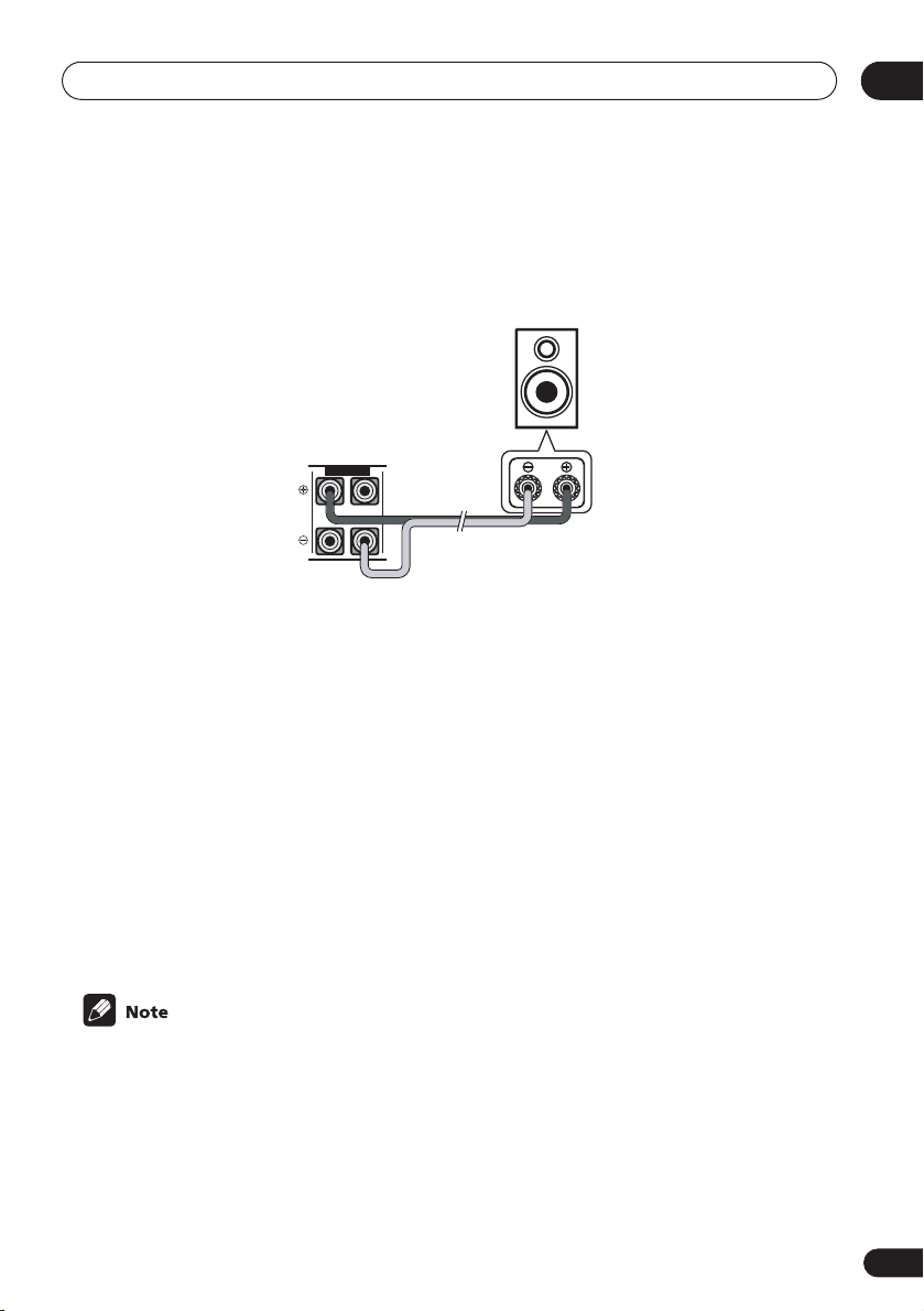
5 minute guide
02
• If you select subwoofer (
SB SW
) in the
Surround back speaker setting
on page 44 you can
hook up a subwoofer instead of speakers to the surround back speaker terminals. Connect
the wires just as above (and as shown below), connecting the positive wire to the right
channel (
+
) terminal, and the negative wire to the left channel (–) terminal.
Surround back
speaker (or
subwoofer)
SURROUND BACK
RL
4 Plug in the receiver and switch it on, followed by your DVD player, your subwoofer
and the TV.
Make sure you’ve set the video input on your TV to this receiver. Check the manual that came
with the TV if you don’t know how to do this.
Also make sure that
is selected. If it isn’t, press
DVD/LD
is showing in the receiver’s display, indicating that the DVD input
DVD
on the remote control to set the receiver to the DVD input.
5 Press QUICK SETUP on the front panel to specify your speaker setup, room size and
listening position.
Use the
Setup
VSX-D914 model only
automatic MCACC setup in the
MULTI JOG
dial to select and
ENTER
to confirm your selection. See
on page 12 if you’re unsure about the settings.
– For a more complete surround sound setup, we recommend using the
Quick surround sound setup
Using the Quick
on page 14.
6 Play a DVD, and adjust the volume to your liking.
There are several other sound options you can select. See
for more on this. See also
Choosing your receiver setup
Listening to your system
on page 35
on page 42 for more setup options.
• Depending on your DVD player or source discs, you may only get digital 2 channel stereo
and analog sound. In this case, the listening mode must be set to
already be set—see
Listening in surround sound
on page 35 if you need to do this) if you
STANDARD
(it should
want multi-channel surround sound.
11
En

02
5 minute guide
Using the Quick Setup
You can use the Quick Setup to get your
system up and running with just a few button
presses. The receiver automatically makes
the necessary settings after you have selected
your speaker setup, room size and listening
position.
If you want to make more specific settings,
refer to
Choosing your receiver setup
page 42.
Use the front panel controls for the steps
below.
VSX-D914 model only
– Note that you don’t
have to make these settings if you use the
automatic MCACC setup instead (in this
case, go straight to the
setup
on page 14).
SB CH
TONE
MODE
SPEAKERS
VIDEO INPUT
S-VIDEO VIDEO
L AUDIO R
Quick surround sound
ENTER
MULTI JOG
QUICK SETUP
MASTER VOLUME
on
MULTI JOG
UPDOWN
3 Use the MULTI JOG dial to choose your
speaker setup.
When a subwoofer was detected in step 2, you
can cycle between the following choices:
2.1ch 3.1ch
7.1ch
4.1ch
6.1ch 5.1ch
If a subwoofer wasn’t detected in step 2, you
can cycle between the following choices:
2.0ch 3.0ch
7.0ch
4.0ch
6.0ch 5.0ch
• Check the table below to find the speaker
setup that corresponds with your system.
12
En
1 If the receiver is off, press
STANDBY/ON to turn the power on.
2 Press QUICK SETUP.
SW DET
flashes in the display while the
receiver checks your setup for a subwoofer.
SW YES
or
SW NO
confirms the subwoofer
check, then the display prompts you to select
your speaker setup.
4 Press ENTER.
5 Use the MULTI JOG dial to choose your
room size.
Depending on the distance of your speakers
from the listening position, choose between
small, medium, or large (
S, M
or L), M being
an average-sized room.

5 minute guide
6 Press ENTER.
7 Use the MULTI JOG dial to choose your
listening position.
You can cycle between the following choices:
FWD
MID
BACK
FWD
– If you are nearer to the front
speakers than the surround speakers
MID
– If you are equal distance from the
front and surround speakers
BACK
– If you are nearer to the surround
speakers than the front speakers
8 Press ENTER to confirm your setup.
The display shows the speaker setup, room
size and listening position that you have
selected.
02
13
En
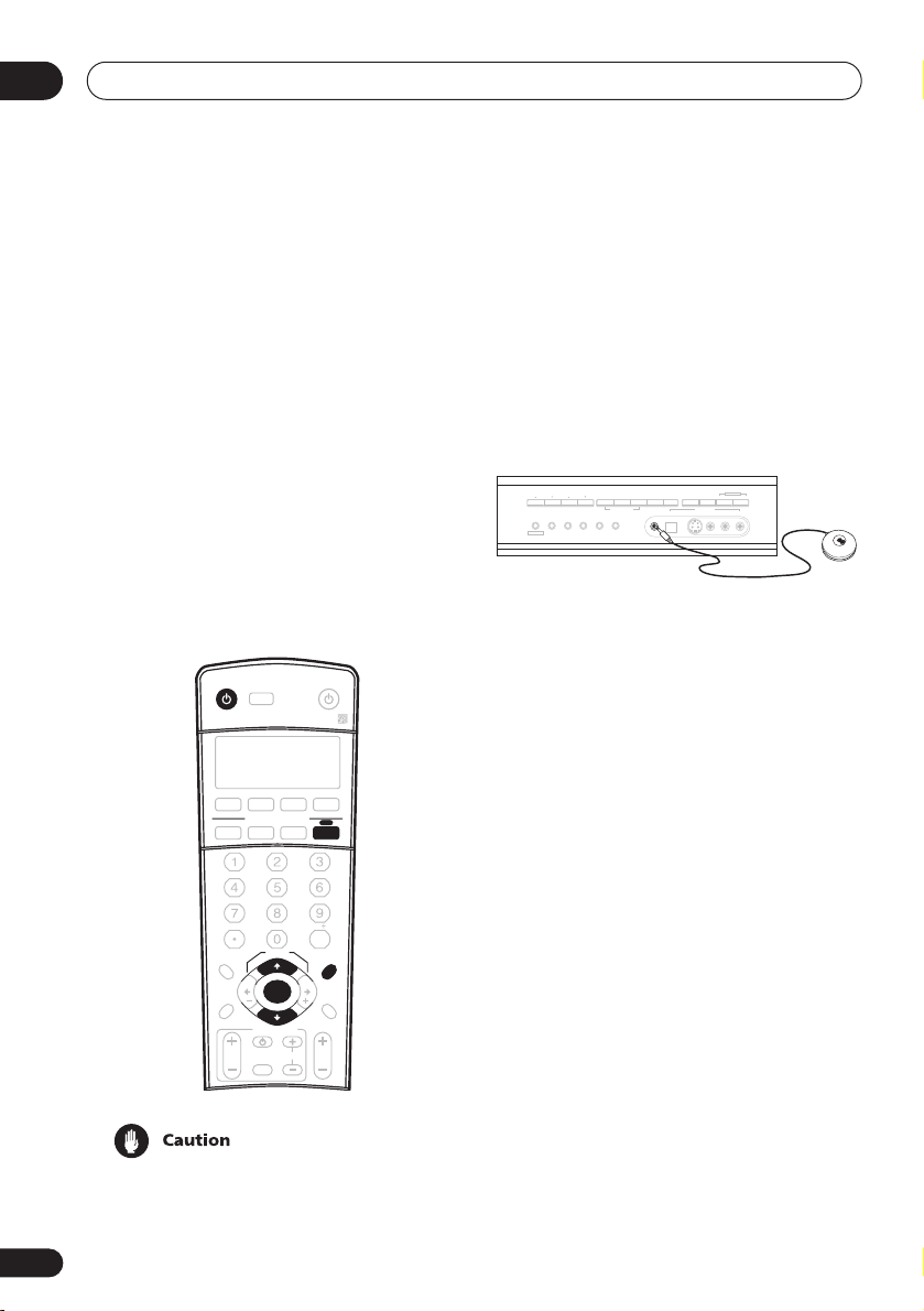
03
Quick surround sound setup
Chapter 3:
Quick surround sound setup
VSX-D914 model only
14
En
Automatically calibrating
your listening area (MCACC)
The Multi-Channel Acoustic Calibration
(MCACC) system measures the acoustic
characteristics of your listening area, taking
into account ambient noise, speaker size and
distance, and tests for both channel delay and
channel level. After you have set up the
microphone provided with your system, the
receiver uses the information from a series of
test tones to optimize the speaker settings
and equalization for your particular room.
INPUT
RECEIVER
DVD/LD TV/SAT DVR/VCR TV CONT
CD
INPUT ATT FL DIMMER SR
+
D.ACCESS
TOP MENU
ST ST
DTV MENU
T.EDIT
GUIDE
TV VOL
• These test tones can be loud, so take care
that there is no one in the room who will
be startled by the noise.
SELECT
MULTI CONTROL
CD-R/TAPE
10
SETUP
TUNE
ENTER
TUNE
TV CONTROL
INPUT
SELECT
SOURCE
TUNER RECEIVER
ENTER
CLASS
MENU
MCACC
BAND
RETURN
TV CH
VOL
DISC
SETUP
• Make sure the mic and speakers are not
moved during the MCACC setup.
1 Connect the microphone to the
MCACC SETUP MIC jack on the front panel.
ADVANCED
STEREO/
TUNING
STATION
MPX
TUNER EDIT
BAND
CLASS
MULTI JOG
SIGNAL
SURROUND
DIRECT
SELECT
STANDARD SPEAKERS
LISTENING MODE
MCACC
FL DIMMER
INPUT ATT
MULTI JOG
MIDNIGHT/
SB CH
LOUDNESS
MODE
TONE
QUICK SETUP
VIDEO INPUT
S-VIDEODIGITAL INSETUP MIC VIDEO
L AUDIO R
2 Place the microphone at your normal
listening position.
Place the mic about ear level at your normal
listening position using the supplied microphone stand on a table or chair.
Make sure there are no obstacles between the
speakers and the microphone.
3 If the receiver is off, press
STANDBY/ON to turn the power on.
4 If you have a subwoofer, turn it on.
5 Press RECEIVER.
6 Press MCACC SETUP.
Try to be as quiet as possible after pressing
MCACC SETUP
. The system outputs a series
of test tones to establish the ambient noise
level.
If the noise level is too high,
NOISY!
blinks in
the display for five seconds. To exit and check
the noise levels again, press
MCACC SETUP
(see the notes regarding ambient noise levels
below) or press
to
GO NEXT?
ENTER
when you’re prompted
The system now checks the microphone and
your speaker setup.
Quick surround sound setup
03
If you see an
there may be a problem with your mic or the
speaker connections.
Turn off the power, and check the problem
indicated by the
then try the auto surround setup again.
•
ERR MIC
connection.
•
ERR Fch
connections.
•
ERR Sch
surround back speaker connections.
•
ERR SW
been switched on and volume on the
subwoofer is turned up.
7 Use and to select the speaker
system that corresponds to your setup.
Cycle between the following choices:
ERR
message in the display,
ERR
message (see below),
– Check the microphone
– Check the front speaker
– Check the surround or
– Make sure the subwoofer has
2.0ch 2.1ch* 3.1ch*3.0ch
7.1ch*
7.0ch
4.0ch
4.1ch*
6.1ch* 6.0ch 5.0ch5.1ch*
* Indicates a subwoofer is included in your
speaker setup
See the table on page 12 if you’re unsure
which speaker system to select.
8 If you selected a speaker system that
includes a subwoofer, press ENTER to
check the subwoofer output level.
If the subwoofer output level is too high/low,
SW.VOL.DWN/SW.VOL.UP
display for five seconds. To exit and check
your subwoofer output level, press
SETUP
(see the notes regarding noise levels
below) or simply press
prompted to
GO NEXT?
blinks in the
ENTER
MCACC
when you’re
9 Press ENTER to finish the auto
surround setup.
The system checks for speaker size, channel
delay and channel level. If you have
connected a subwoofer, it will check for
ambient noise once again.
When the auto surround setup is complete,
the volume level returns to normal and
COMPLETE
display. The MCACC indicator then lights to
show that MCACC setup is complete.
• If the room environment is not optimal for
• Some older TVs may interfere with the
• Using the MCACC system to set up your
• When the
• Depending on the characteristics of your
, then
RESUME
the auto surround setup (too much
ambient noise, echo off the walls, obstacles blocking the speakers from the
microphone) the final settings may be
incorrect. Check for household appliances (air conditioner, fridge, fan, etc.),
that may be affecting the environment
and switch them off if necessary.
operation of the mic. If this seems to be
happening, switch off the TV when doing
the auto surround setup.
speaker system overwrites any previous
settings you had for the
ADVANCED SURROUND
SURROUND
check the settings made with MCACC by
using
levels) or by going through the steps in
Choosing your receiver setup
to check other settings.
room, sometimes identical speakers with
cone sizes of around 5 inches (12cm) will
end up with different size settings. You
can correct the setting manually using
the receiver setup on page 42.
STANDARD
mode is selected, you can
CH SELECT
shows in the
STANDARD
modes.
or
ADVANCED
(to check channel
on page 42
or
15
En
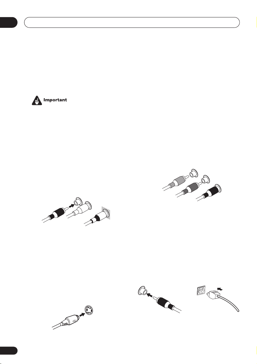
04
Connecting up
Chapter 4:
Connecting up
• Before making or changing any connections, switch off the power and disconnect the power cord from the AC outlet.
Audio/Video cords
Use audio/video cords (not supplied) to
connect the audio/video components and a
video cord to connect the monitor TV.
Connect red plugs to R (right), white plugs to
L (left), and the yellow plugs to
Be sure to insert completely.
R
L
VIDEO
VIDEO
.
Component video cords
Use component video cords to get the best
possible color reproduction of your video
source. The color signal of the TV is divided
into the luminance (
(
PB
and PR) signals and then output. In this
way, interference between the signals is
avoided. Connect from the component video
jacks on the rear of the receiver to the component video jacks on the video component you
are hooking up.
Green
Y
) signal and the color
Y
P
B
Blue
Red
P
R
16
En
S-video cables
Use S-video cables (not supplied) to get
clearer picture reproduction than regular
video cords.
Connect from an S-video jack on the rear of
the receiver to an S-video jack on the video
component you are hooking up.
Be sure to insert completely.
S VIDEO
Digital audio coaxial cords/
Optical cables
Commercially available digital audio coaxial
cords (standard video cords can also be used)
or optical cables (not supplied) are used to
connect digital components to this receiver.
Be sure to insert completely.
Digital audio coaxial cord
(or standard video cord)
Optical cable
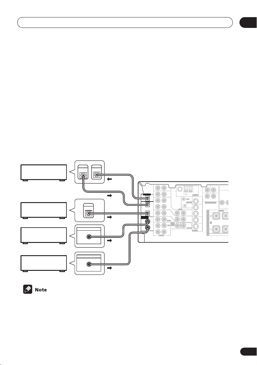
Connecting up
Connecting digital components
The easiest way to hook up this receiver for surround sound is to use a digital input. You can do
this by either coaxial or optical connections (you do not need to do both). The quality of these
two types of connections is the same but since some digital components only have one type of
digital terminal, it is a matter of matching like with like (for example, the coaxial output from the
component to coaxial input on the receiver). This receiver has four digital inputs (two coaxial
inputs and two optical inputs) on the rear panel. Connect your digital components as shown
below.
There is one digital output jack which is marked
input on a digital recorder (for example an MD, DAT or CD-R) you can make direct digital recordings with this unit.
When connecting your equipment, always make sure the power is turned off and the power cord
is disconnected from the AC outlet.
• The arrows indicate the direction of the signal.
DIGITAL
CD recorder
Satellite tuner
CD player
OUT
DIGITAL
OUT
DIGITAL OUT
COAX
DIGITAL
IN
DIGITAL OUT
DIGITAL OUT
OPT
OPT
2
(DVR/VCR)
OPT
1
(TV/
SAT)
ASSIGNABLE
COAX
DIGITAL IN
2
(CD)
COAX
1
(DVD
/LD)
. If you connect this to the optical
CEN-
SUB WOOFER
AUX
IN
IN
OUT
IN
IN
IN
OUT
IN
R
AUDIO
FM UNBAL
Ω
75
CD
DVR/
VCR
TV/
SAT
DVD
/LD
FRONT
REC
CD-R
/ TAPE
/ MD
PLAY
L
OUT
CONTROL
IN
VIDEO
IN
OUT
IN
MONITOR
OUT
D V D
5.1CH
SUB
INPUT
WOOFER
IN
PREOUT
TER
AM
LOOP
ANTENNA
MONITOR OUT
S-VIDEO
OUT
DVR/
VCR
IN
TV/
SAT
IN
DVD
/LD
IN
SURROUND
DVD 5.1CH INPUT
RL
S
P
E
A
A
K
E
R
S
LR
FRONT
MONIT
Y
04
DVD player
DIGITAL OUT
COAX
• If you have an LD player, you need to make special connections to ensure you can play
RF format LDs on your system. If this is the case, hook up your DVD or LD player directly to
an RF demodulator using both the
2
RF output and either a coaxial or optical digital
connection. We also recommend hooking up your digital components to analog audio jacks
as well. Make sure the RF demodulator digital in switch is set correctly (optical or coaxial
depending on the connection). See the component’s instruction manual if you are unsure
about its input and output jacks.
2
17
En
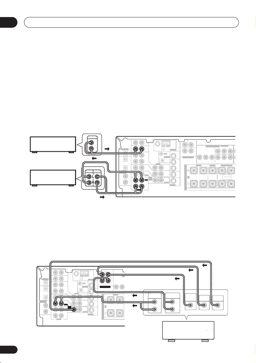
04
Connecting up
Connecting audio components
To begin set up, connect your analog audio components (such as a cassette deck) to the jacks.
For components you want to record with, you need to hook up four plugs to the receiver (a set
of stereo inputs and a set of stereo outputs), but for components that only play, you only need
to hook up one set of stereo plugs. You must also hook up your digital components to analog
audio jacks if you want to record to/from digital components (like an MD) to/from analog components. See page 17 for more on digital connections.
When connecting your equipment, always make sure the power is turned off and the power cord
is disconnected from the AC outlet.
• The arrows indicate the direction of the audio signal.
CEN-
SUB WOOFER
CD player
CD-R/Tape/MD deck
AUX
IN
DIGITAL OUT
IN
OPT
OPT
OUT
2
(DVR/VCR)
IN
OPT
1
(TV/
IN
SAT)
RE
ASSIGNABLE
DIGITAL IN
COAX
2
IN
(CD)
COAX
1
OUT
(DVD
/LD)
IN
R
AUDIO
FM UNBAL
Ω
75
CD
DVR/
VCR
TV/
SAT
DVD
/LD
FRONT
REC
CD-R
/ TAPE
/ MD
PLAY
L
LOOP
OUT
CONTROL
IN
VIDEO
IN
OUT
IN
MONITOR
OUT
D V D
5.1CH
SUB
INPUT
WOOFER
IN
PREOUT
TER
AM
ANTENNA
MONITOR OUT
S-VIDEO
OUT
DVR/
VCR
IN
TV/
SAT
IN
DVD
/LD
IN
DVD 5.1CH INPUT
LR
SURROUND
FRONT
RL
S
P
E
A
A
K
E
R
S
MONITOR OUT
YP
ASSIGNABLE
COMPONENT VIDEO
(
)
DVD/ LD
IN
BPR
YPBP
(
)
TV / SAT
IN
ø
CENTER
SURROUND BACK
RL
SINGLE
SEE INSTRUCTION
MANUAL
¥
R
18
En
Connecting DVD 5.1 channel components
If you prefer to use a seperate component for decoding DVDs, you can connect a decoder or a
DVD player with multi-channel analog outputs to the multi-channel inputs of this receiver. Note
that the multi-channel input can only be used when
When connecting your equipment, always make sure the power is turned off and the power cord
is disconnected from the AC outlet.
• The arrows indicate the direction of the signal.
CEN-
SUB WOOFER
TER
AM
LOOP
ANTENNA
MONITOR OUT
SURROUND
DVD 5.1CH INPUT
IN
OUT
DVR/
VCR
S
IN
P
E
TV/
SAT
A
IN
A
K
DVD
/LD
E
IN
S-VIDEO
R
S
COMPONENT VIDEO
MONITOR OUT
LR
YP
BPR
FRONT
RL R
DIGITAL OUT
(DVR/VCR)
ASSIGNABLE
DIGITAL IN
AUX
IN
IN
OPT
OPT
OUT
2
IN
OPT
1
(TV/
IN
SAT)
COAX
2
IN
(CD)
COAX
1
OUT
(DVD
/LD)
IN
R
AUDIO
FM UNBAL
75
Ω
CD
OUT
DVR/
VCR
TV/
SAT
/ TAPE
PLAY
L
CONTROL
VIDEO
IN
OUT
IN
DVD
MONITOR
/LD
OUT
FRONT
D V D
5.1CH
SUB
INPUT
REC
WOOFER
IN
CD-R
/ MD
PREOUT
DVD 5.1 ch
ASSIGNABLE
(
)
DVD/ LD
IN
¥
YPBP
(
)
TV / SAT
IN
ø
SURROUND BACK
RL
SINGLE
SEE INSTRUCTION
MANUAL
LL
R
RR
FRONT
FRONT
OUTPUT
SURROUND
BACK
CENTER
PREOUT
SURROUND
SURROUND
LR L
L
R
DVD/multi-channel decoder
with multi-channel analog
output jacks
is selected (see page 41).
FRONTCENTER SURROUND
OUTPUT
SUB
CENTER
WOOFER
OUTPUT
AC OUTLET
L
B
R
OUTPUT
VIDEO
OUTPUT
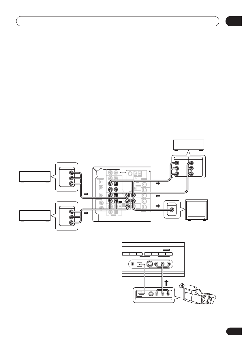
Connecting up
Connecting video components
Connect your video components to the jacks as shown below. With digital video components
(like a DVD player), you must use the connections shown on this page for the video signal, but
in order to hear a digital source (like a DVD) you should hook up the audio to a digital input (see
page 17). It is also a good idea to hook up your digital components with analog audio connections (see page 18).
For better quality video, you can hook up using the component video jacks or the S-video jacks
(quality descends in this order) on the rear of the receiver instead of the regular video jacks.
Make sure they are connected to the video component using the same kind of connection.
When connecting your equipment, always make sure the power is turned off and the power cord
is disconnected from the AC outlet.
• The arrows indicate the direction of the signal
Video deck
INPUT
OUTPUT
VIDEO
VIDEO
L
L
R
R
ASSIGNABLE
LL
(
)
DVD/ LD
IN
¥
YPBP
R
RR
(
)
TV / SAT
FRONT
SURROUND
IN
ø
SURROUND BACK
CENTER SURROUND
RL
SINGLE
SEE INSTRUCTION
MANUAL
TV (monitor)
SURR
TV tuner
(or Satellite tuner)
DVD or LD player
OUTPUT
VIDEO
OUTPUT
VIDEO
CEN-
SUB WOOFER
AUX
IN
L
R
L
DIGITAL OUT
(DVR/VCR)
ASSIGNABLE
DIGITAL IN
IN
OPT
OPT
OUT
2
IN
OPT
1
(TV/
IN
SAT )
COAX
2
IN
(CD)
COAX
1
OUT
(DVD
/LD)
IN
R
FM UNBAL
75
Ω
CD
DVR/
VCR
TV/
SAT
DVD
/LD
FRONT
REC
CD-R
/ TAPE
PLAY
L
AUDIO
OUT
CONTROL
VIDEO
IN
OUT
IN
MONITOR
OUT
D V D
5.1CH
SUB
INPUT
WOOFER
IN
PREOUT
/ MD
TER
AM
LOOP
ANTENNA
MONITOR OUT
SURROUND
DVD 5.1CH INPUT
IN
OUT
DVR/
VCR
S
IN
P
E
TV/
SAT
A
IN
K
DVD
/LD
E
IN
S-VIDEO
R
S
COMPONENT VIDEO
MONITOR OUT
LR
BPR
YP
FRONT
RL R
A
INPUT
VIDEO
R
04
CE
PR
L
Connecting to the front panel video
terminal
Front video connections are accessed via the
front panel using the
standard audio/video jacks as well as an
S-video jack and an optical input. Hook them
up the same way you made the rear panel
connections.
VIDEO
button. There are
STEREO/
SIGNAL
DIRECT
SELECT
DE
MCACC
VSX-D914
MIDNIGHT/
LOUDNESS
DIGITAL OUT
SPEAKERS
S-VIDEODIGITAL INSETUP MIC VIDEO
SB CH
MODE
VIDEO INPUT
VIDEO OUTPUT
TONE
LAUDIOR
LV
MULTI JOG
QUICK SETUP
R
Video
camera
(etc.)
19
En
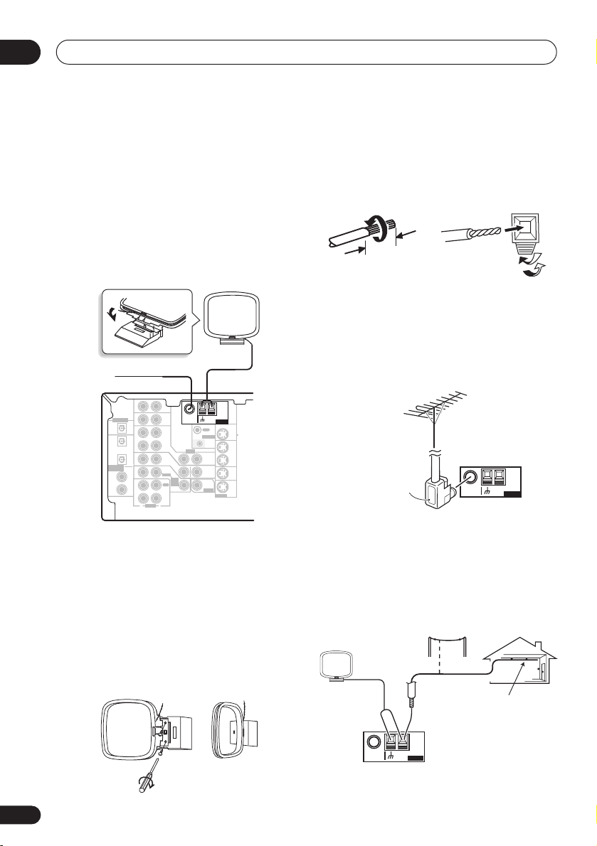
04
Connecting up
Connecting antennas
Connect the AM loop antenna and the FM
wire antenna as shown below. To improve
reception and sound quality, connect external
antennas (see
below). Always make sure that the receiver is
switched off and unplugged from the wall
outlet before making or changing any
connections.
FM wire antenna
Connect the FM wire antenna and fully extend
vertically along a window frame or another
suitable place that gives good reception.
AM loop antenna
Assemble the antenna and connect to the
receiver. Attach (if necessary) and face in the
direction that gives the best reception.
Using external antennas
FM wire antenna
AUX
DIGITAL OUT
ASSIGNABLE
DIGITAL IN
OPT
OPT
(DVR/VCR)
OPT
(TV/
SAT)
COAX
(CD)
COAX
(DVD
/LD)
IN
IN
OUT
2
IN
1
IN
2
IN
1
OUT
IN
FM UNBAL
Ω
75
CD
DVR/
VCR
VIDEO
IN
TV/
SAT
IN
DVD
/LD
FRONT
D V D
5.1CH
INPUT
REC
IN
CD-R
/ TAPE
/ MD
PLAY
R
L
AUDIO
AM loop
antenna
AM
LOOP
ANTENNA
MONITOR OUT
OUT
CONTROL
IN
OUT
MONITOR
OUT
SUB
WOOFER
PREOUT
S-VIDEO
OUT
DVR/
VCR
IN
TV/
SAT
IN
DVD
/LD
IN
Antenna snap connectors
Twist the exposed wire strands together and
insert into the hole, then snap the connector
shut.
3/8 in. (10mm)
Using external antennas
To improve FM reception
Use an F connector to connect an external FM
antenna.
F connector
To improve AM reception
Connect a 15–18 feet length of vinyl-coated
wire to the AM antenna terminal without
disconnecting the supplied AM loop antenna.
For the best possible reception, suspend horizontally outdoors.
Outdoor
antenna
FM UNBAL
75
15–18 ft. (5–6m)
Indoor antenna
(vinyl-coated wire)
AM
Ω
LOOP
ANTENNA
20
En
FM UNBAL
75
AM
Ω
LOOP
ANTENNA
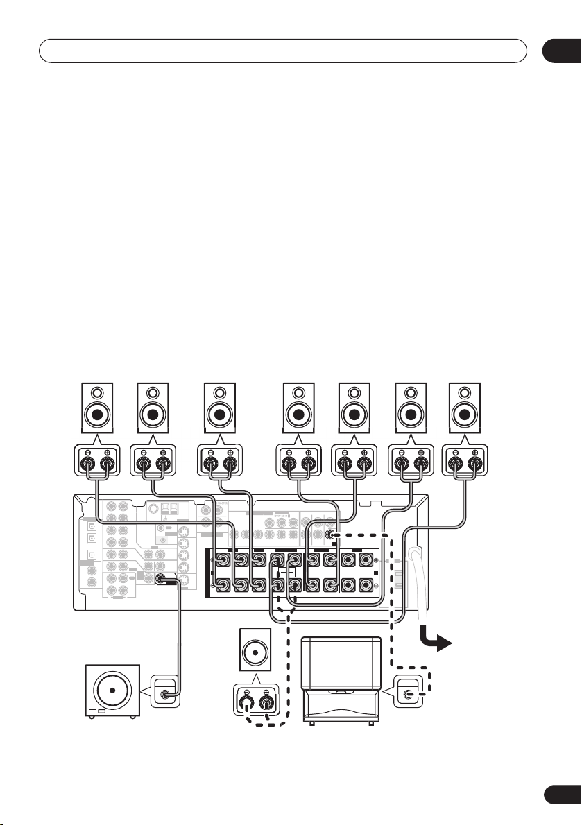
Connecting up
Connecting the speakers
A complete setup of eight speakers (including the subwoofer) is shown below, but everyone’s
home setup will vary. Simply connect the speakers you have in the manner shown below. The
receiver will work with just two stereo speakers (the front speakers in the diagram) but using at
least three speakers is recommended, and a complete setup is best for surround sound. If
you’re not using a subwoofer, change the front speaker setting (see
to large.
Make sure you connect the speaker on the right to the right terminal and the speaker on the left
to the left terminal. Also make sure the positive and negative (
match those on the speakers. You can use speakers with a nominal impedance between 6–16
(please see
impedance of less than 8
Switching the speaker impedance
Ω
).
on page 67 if you plan to use speakers with an
Be sure to complete all connections before connecting this unit to the AC power source.
Speaker setting
+/–
) terminals on the receiver
on page 43)
04
Ω
Front speakers
Center speaker
Surround speakers
LR C LSRS
DIGITAL OUT
IN
OPT
OPT
OUT
2
(DVR/VCR)
IN
OPT
1
(TV/
IN
SAT)
ASSIGNABLE
COAX
DIGITAL IN
2
IN
(CD)
COAX
1
OUT
(DVD
/LD)
IN
Powered
AUX
75
Ω
CD
DVR/
VCR
VIDEO
IN
TV/
SAT
IN
DVD
/LD
FRONT
D V D
5.1CH
INPUT
REC
IN
CD-R
/ TAPE
/ MD
PLAY
R
L
AUDIO
OUT
CONTROL
OUT
MONITOR
OUT
SUB
WOOFER
PREOUT
LOOP
IN
ANTENNA
MONITOR OUT
OUT
DVR/
VCR
TV/
SAT
DVD
/LD
S-VIDEO
Passive
TE
MONITOR OUT
LR
SURROUND
DVD 5.1CH INPUT
IN
IN
IN
BPR
YP
FRONT
RL R
S
P
E
A
A
K
E
R
S
ASSIGNABL
R
RR
FRONT
CENTER
PREOUT
SURROUND
LR L
YPBP
(
)
TV / SAT
IN
ø
SURROUND BACK
RL
SINGLE
SEE INSTRUCTION
MANUAL
FRONTCENTER SURROUND
subwoofer
or single
k
eake
s
TV
Surround back speakers
SBL SBR
AC OUTLET
B
UDIO I
21
En
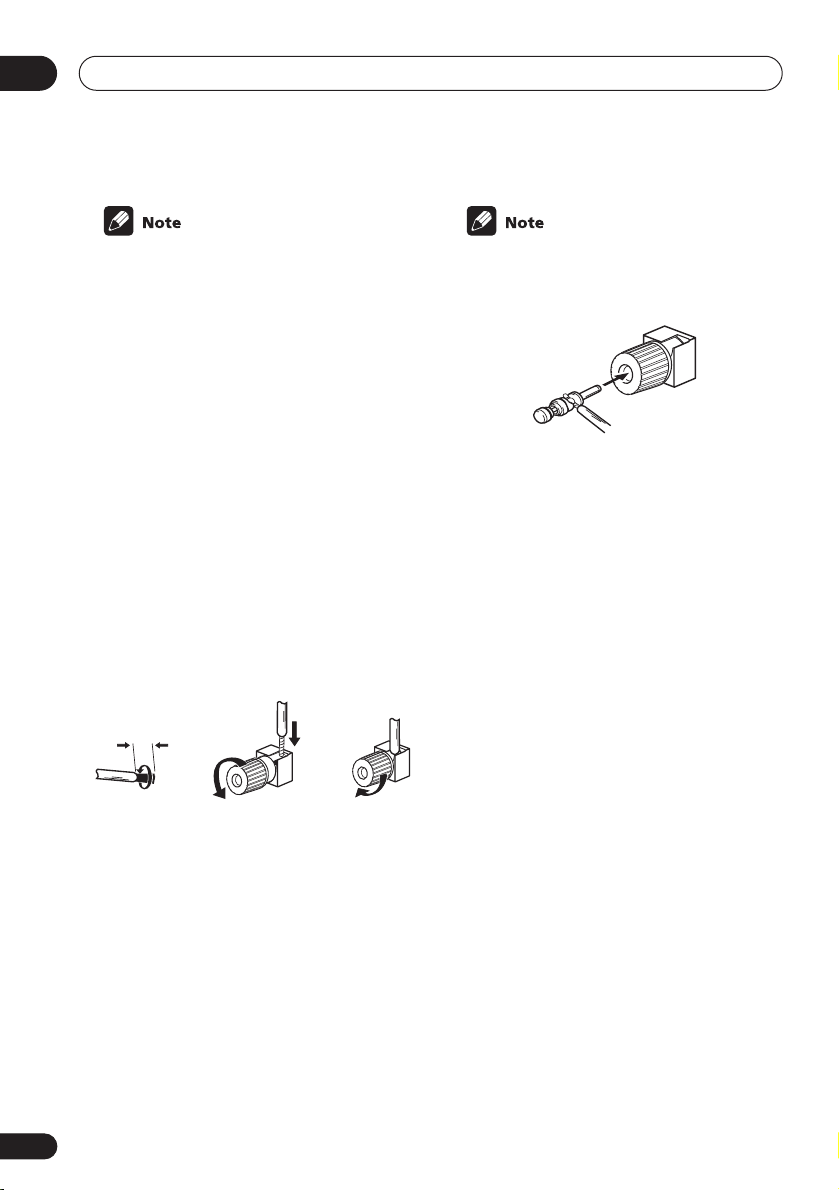
04
Connecting up
• When using the speaker on your TV as the
center speaker (
PREOUT
input jack on your TV. In this case the
center speaker shown is unnecessary.
• If you are using only one surround back
speaker, connect the positive wire to the
right channel (
tive wire to the left channel (
(see illustration on page 10).
• If you select subwoofer (
Surround back speaker setting
you can hook up a subwoofer instead of
speakers to the surround back speaker
terminals. Connect the positive wire to the
right channel (
tive wire to the left channel (
(see illustration on page 11).
C
), connect the
jack on this unit to the audio
+
) terminal, and the nega-
+
) terminal, and the nega-
–
) terminal
SB SW
on page 44
–
) terminal
CENTER
) in the
Speaker terminals
12 3
3/8 in. (10mm)
1 Twist exposed wire strands together.
2 Loosen speaker terminal and insert
exposed wire.
Make sure that all the bare speaker wire is
twisted together and inserted fully into the
speaker terminal. If any of the bare speaker
wire is touching the back panel when you
switch the unit on, the power may cut off as a
safety measure. Use good quality speaker
wire to connect the speakers to the receiver.
3 Tighten terminal.
• The speaker terminals also accept single
banana plugs. (Refer to speaker manual
for details.)
A and B speaker systems
The receiver has two speaker systems: A and
B. A is the main system supporting the full
speaker setup. If you switch on both A and B
speaker systems, only the front speakers and
the (active) subwoofer will be audible. No
sound will come from the center, surround, or
surround back speakers, but multi-channel
sources will be down-mixed to the active
speakers so no sound will be lost. Similarly, if
you choose just the B system you‘ll only hear
the front speakers connected to the B system
and multi channel sources will be downmixed to these two speakers.
• Press the SPEAKERS button on the
front panel to switch between speaker
systems (A, B or both).
Hints on speaker placement
Speakers are usually designed with a particular placement in mind. Some are designed
to be floorstanding, while others should be
placed on stands to sound their best. Some
should be placed near a wall; others should
be placed away from walls. We have provided
a few tips on getting the best sound from your
speakers (following), but you should also
follow the guidelines on placement that the
speaker manufacturer provided with your
particular speakers to get the most out of
them.
22
En
Loading…
Pioneer VSX-D814 Receiver PDF User Guides and Manuals for Free Download: Found (2) Manuals for Pioneer VSX-D814 Device Model (Operating Instructions Manual)
The Pioneer VSX-D814 is a standout receiver that has garnered a solid reputation among audio enthusiasts and home theater aficionados alike. Known for its versatile features and reliable performance, this model exemplifies Pioneer’s commitment to quality and innovation in the audio industry. Whether you’re setting up a home theater system or simply want to enjoy your favorite music with exceptional sound clarity, the VSX-D814 delivers an impressive auditory experience. Let’s dive deeper into what makes this receiver a worthy investment.
One of the most notable features of the Pioneer VSX-D814 is its multi-channel amplification. With 7 channels of amplification, users can enjoy a surround sound experience that truly immerses them in the action, whether they are watching movies or listening to music. The power output is commendable, boasting 100 watts per channel, which is more than sufficient for most home setups. This allows the receiver to handle higher volumes without distortion, ensuring that you can enjoy your entertainment at the levels you desire.
Additionally, the VSX-D814 supports a wide range of audio formats, making it highly compatible with various media devices. It includes support for Dolby Digital and DTS, providing options for superior audio processing. The built-in audio decoder enhances the audio clarity, making it a reliable choice for both small and large rooms. Moreover, thanks to its multiple audio inputs and outputs, you can connect numerous devices, enhancing its functionality in a typical home setup.
Another advantage of the Pioneer VSX-D814 is its user-friendly interface and convenient remote control. Navigating through the settings and adjustments is straightforward, making it accessible for users of varying experience levels. Whether you are a novice or a seasoned audiophile, setting up the receiver to suit your specific needs is a hassle-free endeavor. The graphical user interface further enhances the experience, allowing for easy adjustments during playback.
Moreover, the build quality of the VSX-D814 is impressive, with a durable construction that reflects its high performance. The overall design is sleek and modern, blending seamlessly with other home theater components. Its compact size means that it does not take up excessive space, making it suitable for different environments, whether it’s a dedicated home theater room or a cozy living room.
However, like any product, the Pioneer VSX-D814 is not without its drawbacks. Some users have noted that the receiver’s fan can be a bit noisy during operation, which may be distracting, especially in quieter environments. Additionally, while it does support various audio formats, some advanced users might feel limited by its lack of some of the latest codec support found in more modern receivers.
In conclusion, the Pioneer VSX-D814 is a powerful, reliable, and versatile receiver that offers excellent value for money. Its range of features, from multi-channel amplification to various format support, prepares it well for the demands of modern home entertainment. Although it has minor shortcomings, its strengths far outweigh these issues, making it a solid choice for those looking to enhance their audio experience.
In summary, those considering an upgrade to their audio system should strongly consider the following points about the Pioneer VSX-D814:
- Impressive 7-channel surround sound.
- Powerful audio performance with 100 watts per channel.
- Supports various audio formats, including Dolby Digital and DTS.
- User-friendly interface and remote control.
- Durable build quality with a sleek design.
Ultimately, the Pioneer VSX-D814 stands as a tribute to what makes Pioneer a respected name in the audio industry. It combines performance, usability, and style, ensuring that users can enjoy their audio without compromise.
Connecting up
Connecting the speakers (VSX-D814)
A complete setup of eight speakers (including the subwoofer) is shown below, but everyone’s home setup will vary. Simply connect the speakers you have in the manner shown below. The receiver will work with just two stereo speakers (the front speakers in the diagram) but using at least three speakers is recommended, and a complete setup is best for surround sound. If you’re not using a subwoofer, change the front speaker setting (see Speaker setting on page 46) to large.
Make sure you connect the speaker on the right to the right terminal and the speaker on the left to the left terminal. Also make sure the positive and negative (+/–) terminals on the receiver match those on the speakers. You can use speakers with a nominal impedance between 6–16Ω(please see Switching the speaker impedance on page 72 if you plan to use speakers with an impedance of less than 8Ω).
Be sure to complete all connections before connecting this unit to the AC power source.
Front speakers |
Center speaker |
Surround speakers |
Surround back speakers |
|||||||||||
|
L |
R |
C |
LS |
RS |
SBL |
SBR |
||||||||
03
English Italiano Français Deutsch
|
IN |
AUX |
|||||||
|
DIGITAL OUT |
FM UNBAL |
AM |
||||||
|
IN |
CD |
75 Ω |
LOOP |
ANTENNA |
||||
|
OPT |
MONITOR |
OUT |
||||||
|
OUT |
||||||||
|
OPT |
OUT |
DVR/ |
CONTROL |
|||||
|
2 |
VCR |
IN |
||||||
|
(DVR/VCR) |
IN |
VIDEO |
OUT |
|||||
|
OPT |
DVR/ |
|||||||
|
1 |
TV / |
IN |
OUT |
VCR |
||||
|
(TV / |
IN |
SAT |
IN |
|||||
|
ASSIGNABLE |
SAT) |
IN |
||||||
|
COAX |
DVD |
|||||||
|
DIGITAL IN |
MONITOR |
TV/ |
||||||
|
2 |
/LD |
OUT |
SAT |
|||||
|
(CD) |
IN |
FRONT |
IN |
|||||
|
D V D |
||||||||
|
COAX |
REC |
5.1CH |
SUB |
DVD |
||||
|
1 |
INPUT |
WOOFER |
||||||
|
OUT |
CD-R |
IN |
PREOUT |
/LD |
||||
|
(DVD |
||||||||
|
/ TAPE |
IN |
|||||||
|
/LD) |
/ MD |
S-VIDEO |
||||||
|
IN |
PLAY |
|||||||
|
R |
AUDIO |
L |
|
TERCEN- |
SUB WOOFER |
|||||||||
|
COMPONENT VIDEO |
ASSIGNABLE |
L |
L |
SURROUND |
||||||
|
( DVD / LD) IN ¥ |
BACK |
|||||||||
|
R |
L |
MONITOR OUT |
||||||||
|
SURROUND |
||||||||||
|
DVD 5.1CH INPUT |
||||||||||
|
Y |
PB |
PR |
Y |
PB |
PR |
R |
R |
CENTER |
||
|
(T V / SAT) IN ø |
FRONT |
SURROUND |
PREOUT |
|||||||
|
S |
R FRONT |
L |
CENTER |
R SURROUND BACK L |
R |
SURROUND |
L |
R FRONT L |
||
|
P |
||||||||||
|
E |
||||||||||
|
A |
A |
SINGLE |
B |
|||||||
|
K |
SEE INSTRUCTION |
|||||||||
|
MANUAL |
E
R
S
Nederlands
VSX-D814
|
Passive |
||
|
Powered subwoofer |
subwoofer |
|
|
or single |
||
|
SW |
||
|
surround |
||
back |
||
|
INPUT |
speaker |
En