
Данное руководство содержит подробные инструкции и сведения о функционировании и использовании принтера Ricoh SP 150 / SP 150w / SP 150SU / SP 150 SUw. Перед использованием устройства внимательно ознакомьтесь с данным руководством для получения информации о его возможностях и мерах безопасности.
Содержание руководства:
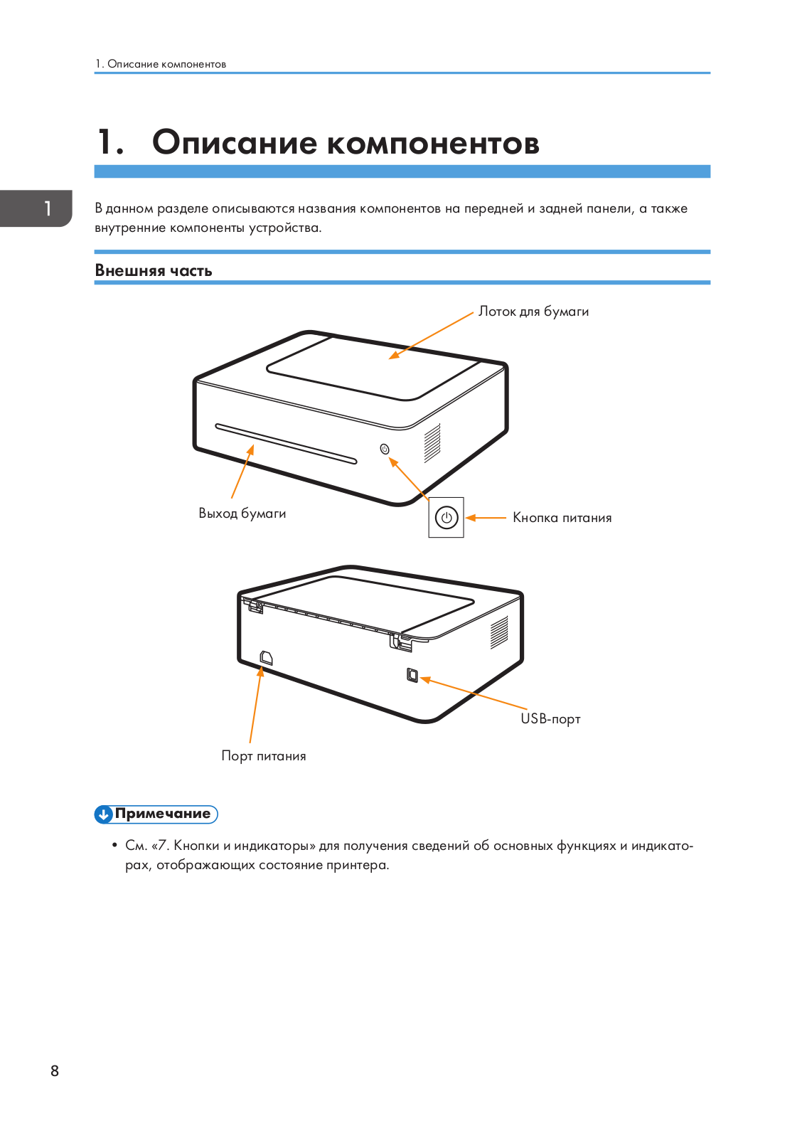
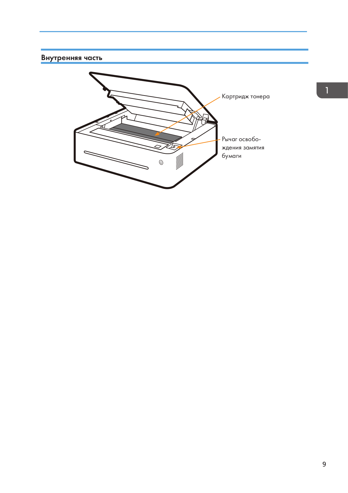
1. Описание компонентов;
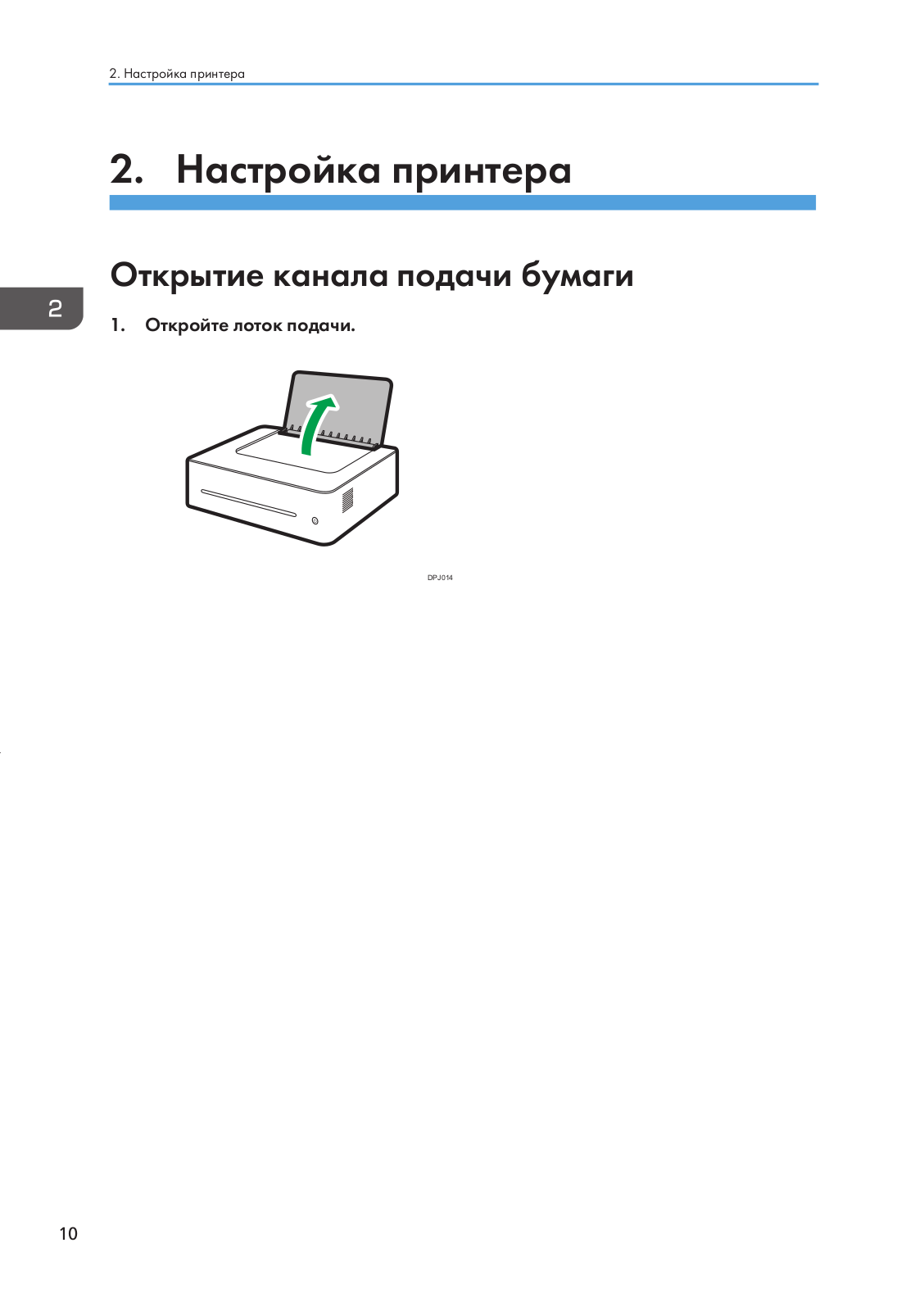
2. Настройка принтера;
3. Материалы для печати;
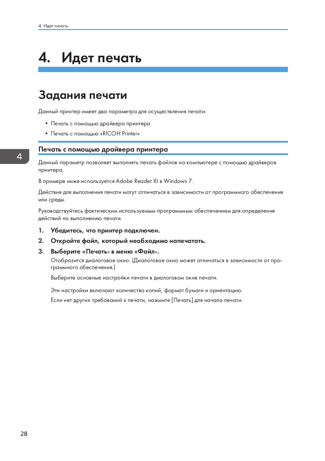
4. Идет печать;
5. Драйверы;
6. Печать по Wi-Fi;
7. Кнопки и индикаторы;
8. Обслуживание устройства;
9. Устранение неисправностей;
10. Конфигурации принтера (ВЕБ-страница);
11. Приложение.
Скачать руководство
Все материалы на сайте представлены исключительно для ознакомления. Все торговые марки и права на публикуемые материалы принадлежат их владельцам.
All materials on the site are presented solely for information. All trademarks and copyrights in the published materials belong to their respective owners.
Ricoh
Loading…
S
- sft2702
- SG 2100N
- SG 3100SNw2
- SG 3110DN7
- SG 3110DNW
- SG 3110SFNw2
- sg3500
- SG 7100DN2
- SGC 15064
- SGC 1506 GS
- SGC 1808
- SG K3100DN2
- SG Series2
- SH3070
- SH-P1 M020
- SH-P1 M021
- silver7
- Singlex
- SINGLEX TLS
- siubli-trans XPRES GXe7700N
- SLP26
- SLP26n
- Smart Operation Panel
- SMFC210M
- SMFC210M SecureFax
- SP 1002
- SP 1000S4
- SP 1000SF3
- SP 100 e5
- SP 100SF3
- SP 100SF e4
- SP 100SU3
- SP 100SU e3
- SP 1109
- SP 1100S4
- SP 1100SF3
- SP 110Q
- SP 110SF2
- SP 110SU3
- SP 110suq
- SP 11110
- SP 111SF3
- SP 111 SU4
- SP 1129
- SP 112SF2
- SP 112su3
- SP 12002
- SP 1200S2
- SP 1200SF6
- SP 1210N7
- SP 1504
- SP 150SU3
- SP 150SUW2
- SP 150w4
- SP 2008
- SP 200n6
- SP 200nw2
- SP 200s7
- SP 200SF3
- SP 201N8
- SP 201Nw6
- SP 201S2
- SP 201SF3
- SP 202S2
- SP 202SF3
- SP 202SN3
- SP 203S2
- SP 203SF4
- SP 203SFN4
- SP 203SFNw2
- SP 204SF10
- SP 204SFN11
- SP 204SFNw8
- SP 204SN12
- SP 21010
- SP 210S
- SP 210 SF7
- SP 210SU7
- SP 21112
- SP 211SF4
- SP 211SU5
- SP 2126
- SP 212NW7
- SP 212 SFNw7
- SP 212SFw5
- SP 212 SNw6
- SP 212SUw5
- SP 212W6
- SP 2136
- sp 213FNw
- SP 213NW7
- SP 213SFNW4
- SP 213SFw4
- SP 213SNw4
- SP 213SUW4
- SP 213w6
- SP 220NW3
- SP 220 SFNW2
- SP 220SNW3
- SP 221
Loading…
Loading…
Nothing found
SP 150
User Guide
102 pgs4.59 Mb0
User Manual
50 pgs9.96 Mb0
User Manual
103 pgs4.6 Mb0
User Manual [ru]
103 pgs4.58 Mb0
Table of contents
Loading…
…
Ricoh User Manual [ru]
Download
Specifications and Main Features
Frequently Asked Questions
User Manual


Loading…
+ 73 hidden pages
You need points to download manuals.
1 point = 1 manual.
You can buy points or you can get point for every manual you upload.
Buy points
Upload your manuals
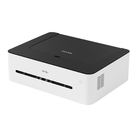
Принтер – это устройство, которое является техническим чудом современности и помогает нам в повседневной жизни. Одним из надежных и многофункциональных принтеров является Ricoh SP 150. В данной статье мы рассмотрим основные особенности и функции данной модели, а также предоставим подробную инструкцию по ее эксплуатации.
Основные характеристики Ricoh SP 150
Ricoh SP 150 – это лазерный принтер, который отличается высокой скоростью печати и качественными результатами. Этот принтер идеально подходит как для домашнего использования, так и для офисной работы.
- Скорость печати: до 22 страниц в минуту.
- Разрешение печати: 1200 x 600 точек на дюйм.
- Время разогрева: менее 25 секунд.
- Месячный ресурс: до 20 000 страниц.

Благодаря своим компактным размерам и небольшому весу, принтер легко поместится на рабочем столе или в уголке комнаты. Однако, несмотря на свои небольшие размеры, Ricoh SP 150 обладает высокой производительностью.
Инструкция по эксплуатации Ricoh SP 150
Для начала использования принтера Ricoh SP 150 следуйте следующим рекомендациям:
- Шаг 1: Распакуйте принтер. Убедитесь, что все комплектующие находятся внутри.
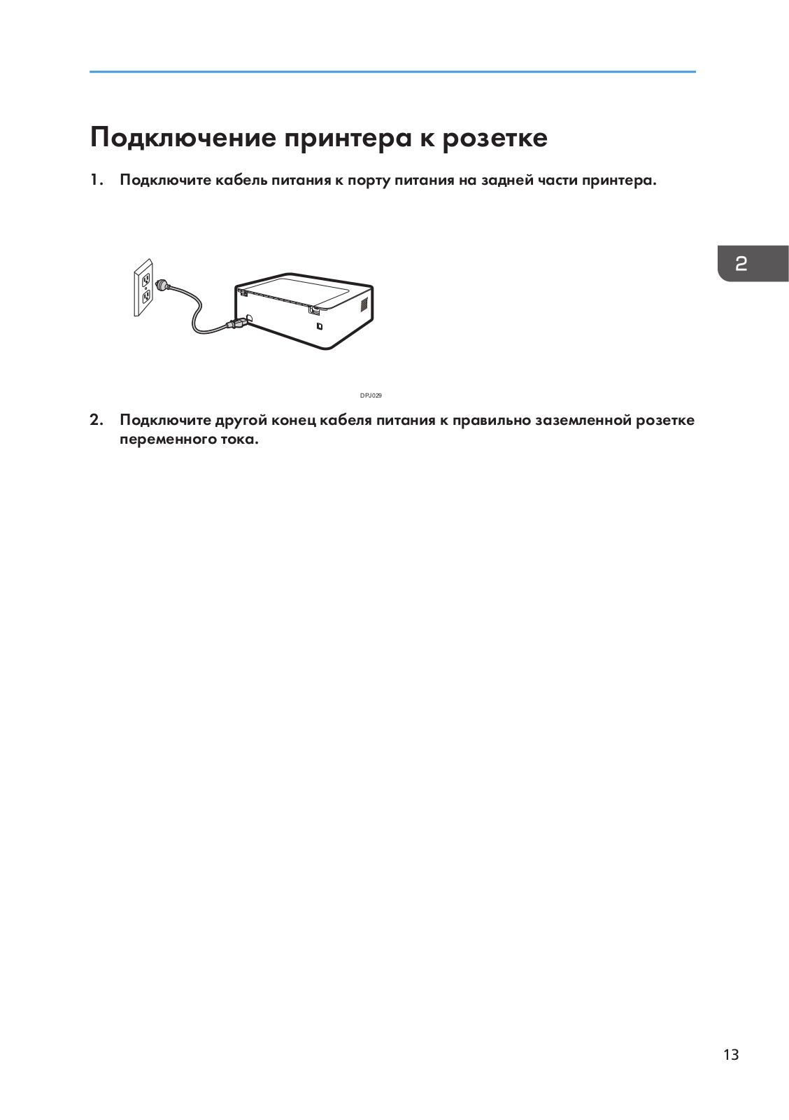
- Шаг 2: Подключите принтер к источнику питания и компьютеру при помощи соответствующих кабелей.
- Шаг 3: Включите принтер и дождитесь его разогрева. Это занимает всего несколько секунд.
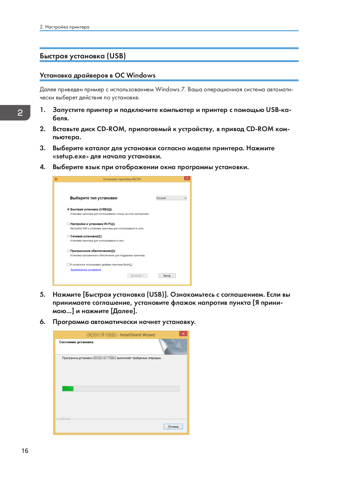
- Шаг 4: Установите необходимые драйверы и программное обеспечение для принтера с помощью прилагаемого диска или загрузите их с официального сайта производителя.
- Шаг 5: Откройте программу для печати и выберите принтер Ricoh SP 150 в качестве устройства вывода.
- Шаг 6: Загрузите бумагу в лоток для печати.
- Шаг 7: Настройте необходимые параметры печати, такие как формат бумаги, тип материала и качество печати.
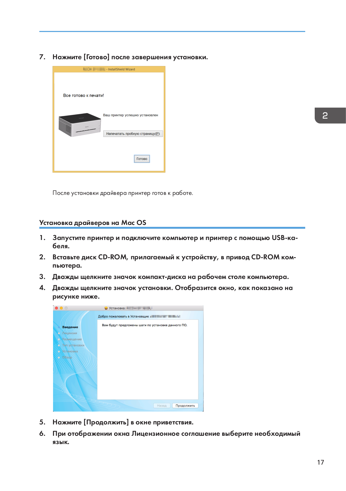
- Шаг 8: Нажмите кнопку «Печать» и дождитесь окончания процесса.
- Шаг 9: После завершения печати выключите принтер и отсоедините его от источника питания.
Следуя вышеуказанным шагам, вы сможете настроить принтер Ricoh SP 150 и начать использовать его в своих целях. Рекомендуется ознакомиться с дополнительной информацией по настройке принтера в инструкции, которая прилагается к нему при покупке.
Итог

Принтер Ricoh SP 150 – надежное и производительное устройство, которое без проблем справляется с любыми печатными задачами. Он не только выдает высококачественные отпечатки, но и обладает удобной системой эксплуатации. Благодаря своим компактным размерам, он может быть установлен в любом удобном месте, и сэкономит пространство на вашем рабочем столе.
Принтер Ricoh SP 150 – это надежный помощник в выполнении любых печатных задач!
Принтер Ricoh SP 150: инструкция по эксплуатации
В наше время принтеры являются неотъемлемой частью нашей повседневной жизни. Они позволяют нам быстро и качественно печатать документы, изображения и другие материалы. Один из надежных и функциональных принтеров на рынке — это модель Ricoh SP 150. В этой статье мы рассмотрим основные возможности данного устройства и подробную инструкцию по его эксплуатации.
Основные характеристики принтера Ricoh SP 150
- Тип печати: лазерная
- Формат бумаги: A4
- Скорость печати: до 22 страниц в минуту
- Разрешение печати: 1200×600 точек на дюйм
- Подключение: USB 2.0

Принтер Ricoh SP 150 — это надежное устройство, которое отлично подходит как для домашнего использования, так и для малого офиса. Он обладает высокой скоростью печати, что позволяет сэкономить время и сделать больше работы за короткий промежуток времени. Благодаря лазерной технологии печати, печатные материалы имеют четкий и контрастный вид.
Инструкция по эксплуатации принтера Ricoh SP 150
- Шаг 1: Распаковка
Перед использованием принтера необходимо осуществить его распаковку. Внимательно извлеките принтер из упаковки, проверьте наличие всех комплектующих и убедитесь, что ничего не повреждено.
- Шаг 2: Подключение к компьютеру

Соедините принтер с компьютером с помощью USB-кабеля. Убедитесь в правильности подключения и кабеля, и входов на принтере и компьютере.
- Шаг 3: Установка драйверов
Перед началом работы с принтером убедитесь, что у вас установлены все необходимые драйверы. Если нет, скачайте их с официального сайта Ricoh, установите на компьютер и следуйте указаниям программы установки.
- Шаг 4: Загрузка бумаги
Откройте лоток для бумаги, установите нужное количество листов и правильно его закройте. Убедитесь, что бумага находится правильно, чтобы избежать замятий и заторов.
- Шаг 5: Печать
Теперь, когда все готово, вы можете приступить к печати документов. Откройте документ на компьютере, выберите «Печать» и укажите нужные настройки — кол-во копий, ориентацию бумаги и т.д. Затем нажмите «Печать» и дождитесь окончания процесса печати.

Итог
Принтер Ricoh SP 150 — это надежное и производительное устройство, которое отлично подходит для домашнего использования и малых офисов. Благодаря его функциональности и высокой скорости печати, вы сможете оперативно и качественно печатать нужные документы. При эксплуатации принтера рекомендуется следовать инструкции, чтобы избежать возможных проблем. Надеемся, что данная статья помогла вам разобраться с основными возможностями и принципами работы принтера Ricoh SP 150.
Принтер Ricoh SP 150: инструкция по эксплуатации
Добро пожаловать в мир высококачественной печати с принтером Ricoh SP 150! В этой статье мы расскажем вам о всех особенностях и функциях данной модели, а также предоставим подробную инструкцию по ее эксплуатации. Уже сейчас готовьтесь к новым возможностям и превосходным результатам печати!
Основные преимущества принтера Ricoh SP 150
- Высокое качество печати. Благодаря разрешению 1200 x 600 точек на дюйм, принтер Ricoh SP 150 способен выводить на печать детали и текст с невероятной четкостью и детализацией.
- Быстрая скорость печати. Скорость печати до 22 страниц в минуту позволяет справляться с большими объемами работы без перерывов и ожидания.
- Надежность и долговечность. Принтер Ricoh SP 150 создан с использованием высококачественных материалов, что обеспечивает его долгую и надежную работу.
- Экономичность. Принтер оснащен технологией энергосбережения, благодаря которой потребление электроэнергии минимизируется, что положительно влияет на экологию и ваши расходы.
Подготовка к работе
Перед началом работы с принтером Ricoh SP 150 необходимо убедиться в следующем:
- Проверьте наличие всех компонентов: сам принтер, кабель питания, кабель USB и при необходимости, картридж с чернилами.
- Разместите принтер на ровной и устойчивой поверхности вблизи розетки. Убедитесь, что принтер не перегревается и вентиляционные отверстия не заблокированы.
- Подключите принтер к источнику питания и компьютеру с помощью кабеля USB.
Установка драйвера и программного обеспечения

Прежде чем использовать принтер Ricoh SP 150, необходимо установить драйвер и программное обеспечение. Следуйте этим шагам:
- Вставьте прилагаемый диск с драйвером и программным обеспечением в CD/DVD-привод компьютера.
- Следуйте инструкциям на экране, чтобы установить необходимые драйверы и программы. Если диск отсутствует или у вас нет доступа к CD/DVD-приводу, посетите официальный сайт Ricoh и загрузите последнюю версию драйвера и программного обеспечения.
- Перезагрузите компьютер после установки.
Использование принтера

Как только вы завершили установку драйвера и программного обеспечения, вы готовы начать использовать принтер Ricoh SP 150. Ниже приведена инструкция по основным функциям устройства:
- Откройте документ, который вы хотите напечатать.
- Нажмите на команду «Печать» в программе, которая используется для открытия документа.
- В окне печати выберите принтер Ricoh SP 150.
- Настройте необходимые параметры печати, такие как формат бумаги, ориентацию и качество печати.
- Нажмите кнопку «Печать» для начала печати.
Обслуживание и замена расходных материалов
Чтобы долго наслаждаться безупречным качеством печати принтера Ricoh SP 150, регулярно выполняйте следующее обслуживание:
- Очищайте принтер от пыли и грязи с помощью мягкой сухой ткани.
- Заменяйте картридж с чернилами при необходимости согласно инструкциям, указанным в руководстве пользователя.
- Не допускайте перегрузки бумаги в лотке для подачи. Проверяйте, чтобы бумага была правильно уложена и не застревала.
Принтер Ricoh SP 150 — это сочетание качественной печати, надежности и удобства эксплуатации. Благодаря своим многофункциональным возможностям и простой инструкции, принтер станет незаменимым помощником в вашей работе или доме. Насладитесь беспроблемной печатью и получите профессиональные результаты прямо у себя!
Итог
В данной статье мы рассмотрели ключевые особенности принтера Ricoh SP 150, а также предоставили подробную инструкцию по его эксплуатации. Отличающиеся высоким качеством печати, быстрой скоростью и экономичностью, этот принтер является идеальным выбором для тех, кто ценит комфорт и надежность. Помните, что регулярное обслуживание и замена расходных материалов помогут сохранить принтер в отличном состоянии и продлить его срок службы. Не сомневайтесь в своем выборе и наслаждайтесь качественной печатью!
- Manuals
- Brands
- Ricoh Manuals
- All in One Printer
- SP 150
- Field service manual
-
Contents
-
Table of Contents
-
Troubleshooting
-
Bookmarks
Quick Links
Model Rev-P1/MF1
Machine Codes:
SFP: M290/M0AF
MFP: M291/M0AE
Field Service Manual
January, 2016
Need help?
Do you have a question about the SP 150 and is the answer not in the manual?
Questions and answers
Related Manuals for Ricoh SP 150
Summary of Contents for Ricoh SP 150
-
Page 1
Model Rev-P1/MF1 Machine Codes: SFP: M290/M0AF MFP: M291/M0AE Field Service Manual January, 2016… -
Page 3: Important Safety Notices
Important Safety Notices Warnings, Cautions, Notes In this manual, the following important symbols and notations are used. • A Warning indicates a potentially hazardous situation. Failure to obey a Warning could result in death or serious injury. • A Caution indicates a potentially hazardous situation. Failure to obey a Caution could result in minor or moderate injury or damage to the machine or other property.
-
Page 4: Responsibilities Of The Customer Engineer
Where symbols are used on or near switches on machines for Europe and other areas, the meaning of each symbol conforms with IEC60417. Responsibilities of the Customer Engineer Customer Engineer Replacement shall be done only by trained customer engineers who have completed service training for the machine and all optional devices designed for use with the machine.
-
Page 5: Installation, Replacement, And Adjustments
• After turning the machine on with any cover removed, keep your hands away from electrical components and moving parts. Never touch the cover of the fusing unit, gears, timing belts, etc. Installation, Replacement, and Adjustments • After installation, replacement, or adjustment, always check the operation of the machine to make sure that it is operating normally.
-
Page 6: Organic Cleaners
operation of the machine to ensure that it is operating normally and safely after removal and replacement of any safety device. • For replacements use only the correct fuses or circuit breakers rated for use with the machine. Using replacement devices not designed for use with the machine could lead to a fire and personal injuries.
-
Page 7: After Maintenance
• Connect the power cord directly into the power source. Never use an extension cord. • When you disconnect the power plug from the power source, always pull on the plug, not the cable. After Maintenance Disposal of Used Items •…
-
Page 8: Special Safety Instructions For Toner
• Caution operators about removing paper fasteners around the machine. They should never allow paper clips, staples, or any other small metallic objects to fall into the machine. Special Safety Instructions for Toner Accidental Physical Exposure • Work carefully when removing paper jams or replacing toner bottles or cartridges to avoid spilling toner on clothing or the hands.
-
Page 9: Toner Disposal
• Always store fresh toner supplies or empty bottles or cartridges in a cool, dry location that is not exposed to direct sunlight. Toner Disposal • Never attempt to incinerate toner, used toner, or empty toner containers (bottles or cartridges). Burning toner can explode and scatter, causing serious burns.
-
Page 10: Observance Of Electrical Safety Standards
2. To avoid possible accumulation of ozone in the work area, locate the machine in a large well ventilated room that has an air turnover rate of more than 30m /hr/person. 3. Toner and developer are non-toxic, but if you get either of them in your eyes by accident, it may cause temporary eye discomfort.
-
Page 11: Rohs Compliance
• Use of controls, or adjustment, or performance of procedures other than those specified in this manual may result in hazardous radiation exposure. • Turn off the main switch before attempting any of the procedures in the Laser Unit section. Laser beams can seriously damage your eyes.
-
Page 12: Symbols, Abbreviations And Trademarks
Symbols, Abbreviations and Trademarks Symbols and Abbreviations Commonly Used Icons for Replacements and Adjustments This manual uses several symbols and abbreviations. The meaning of those symbols and abbreviations are as follows: Clip ring Screw Connector Clamp E-ring C-ring Spring Timing Belt Paper Feed: SEF/LEF The notations «SEF»…
-
Page 13: Key Presses
In this manual «Main Scan» means «Horizontal» and «Sub Scan» means «Vertical», both relative to the direction of paper feed. Key Presses Symbol What It Means [Key] The names of machine keys and PC keyboard keys are enclosed in square brackets. >…
-
Page 14: Table Of Contents
TABLE OF CONTENTS Important Safety Notices……………………… 1 Warnings, Cautions, Notes………………………1 General Safety Instructions……………………..1 Responsibilities of the Customer Engineer………………..2 Customer Engineer……………………..2 Reference Material for Maintenance………………..2 Before Installation, Maintenance……………………2 Shipping and Moving the Machine………………… 2 Power…………………………2 Installation, Replacement, and Adjustments………………3 Special Tools……………………….3 During Maintenance……………………….
-
Page 15
Paper Feed: SEF/LEF…………………….. 10 Key Presses……………………….11 Trademarks…………………………11 1. Product Information Specifications…………………………17 Specifications of the Machine……………………17 Software Specifications……………………..17 New Product Information……………………..18 Series Comparison……………………….18 Machine Names and Host Interface………………..18 Feature Summary……………………..18 Important Points to Remember………………….19 General Configuration……………………..19 Product Overview………………………. -
Page 16
After Replacing the Laser Unit………………….31 Paper Feed…………………………..32 Paper Feed Roller……………………….32 Friction Pad…………………………33 Registration Roller……………………….34 Image Transfer Roller………………………34 Paper Feed Clutch……………………….36 Bottom Plate Lift Clutch……………………..36 Drive……………………………. 38 Main Motor…………………………38 Fan…………………………….41 Fan…………………………..41 Fusing Unit……………………………42 Fusing Unit…………………………42 Electrical Components……………………….. -
Page 17
Adjust Registration……………………..55 Adjust Temperature……………………..56 Adjust Other Settings………………………57 Get Input Status……………………… 59 Output Check……………………….60 Data Upload……………………….61 CIS Calibration……………………….61 Firmware Update……………………….. 62 5. Troubleshooting Service Calls…………………………63 LED Indicators and Error Status……………………63 Points to Note……………………….63 Fatal SC Codes/Fusing Related Errors…………………. 64 Executing Fusing SC Reset……………………64 SC Tables…………………………65 SC Table Key……………………….65… -
Page 19: Product Information
1. Product Information Specifications Specifications of the Machine For details about machine specifications, see the user guide. Software Specifications For details about system requirements for drivers, see the user guide. For details about system requirements for the Virtual Operation Panel, see the manual for the Virtual Operation Panel.
-
Page 20: New Product Information
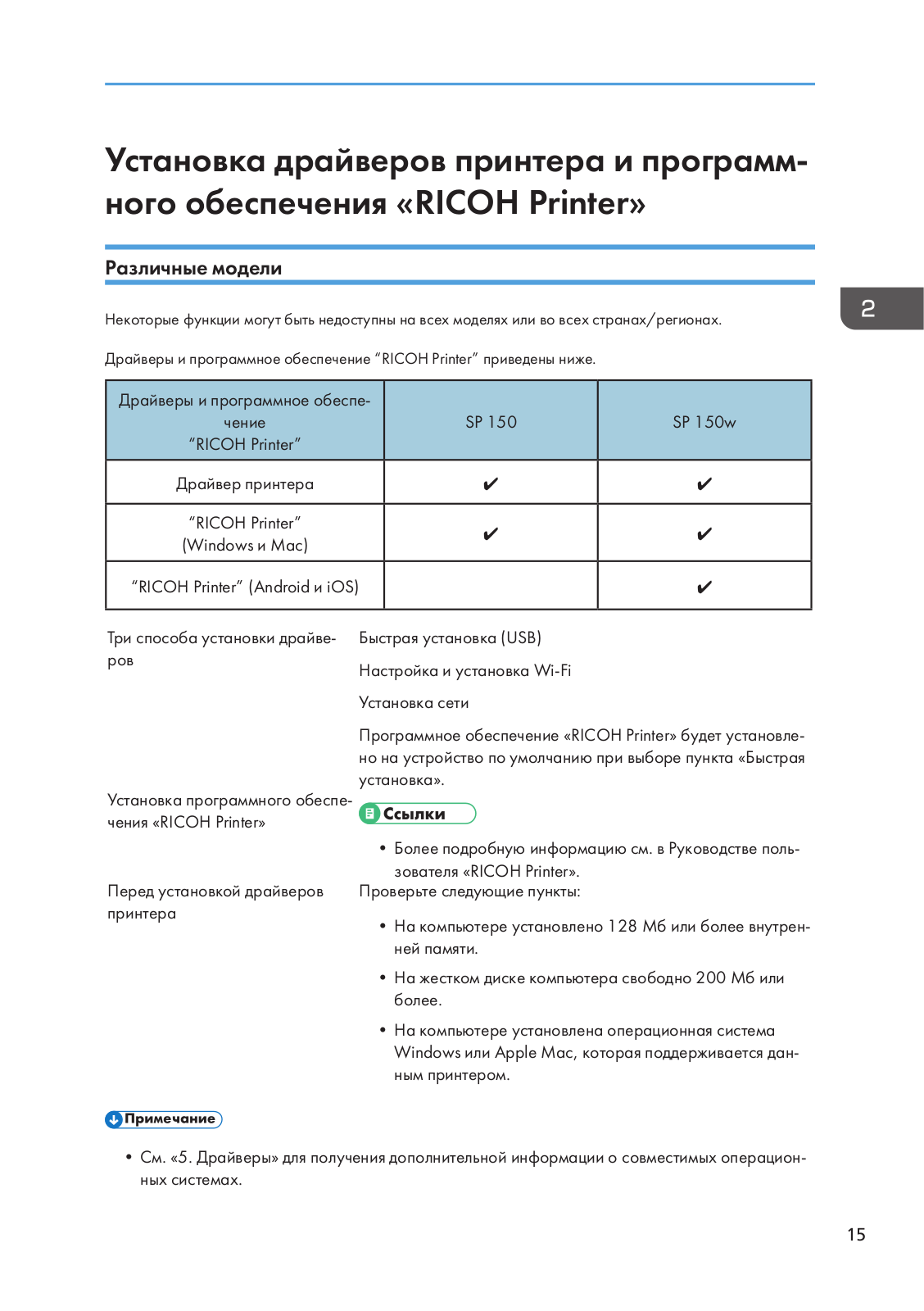
1. Product Information New Product Information Series Comparison Machine Names and Host Interface Abbrev. Model No. Product Name Host Interface M290-27/29 SP 150 USB2.0 USB2.0 M0AF-17/27/2 SP 150w Wi-Fi 802.11b/g/n M291-27/29 SP 150SU USB2.0 USB2.0 M0AE-17/27/2 SP 150SUw Wi-Fi 802.11b/g/n Comparison of SFP and MFP Models Abbrev.
-
Page 21: Important Points To Remember
New Product Information Feature Virtual Operation Panel Available Available Firmware update tool Available (English and Simplified Chinese) CE Tools Available Available Toner End Detection • Toner Near End A Toner Near End message is displayed on the Virtual Operation Panel. Printing can be continued.
-
Page 22: Product Overview
1. Product Information Product Overview Paper Path and Image Writing Name Name Lenses, Mirrors Registration Sensor Polygon Mirror Drum Paper Size Sensor Image Transfer Roller Paper Tray Hot Roller Bottom Plate Position Sensor Pressure Roller Paper Feed Roller Paper Exit Roller Registration Roller Exit Sensor Paper Transport Roller…
-
Page 23: Drive Layout
New Product Information Drive Layout Name Name Paper Feed Clutch Drum (inside the AIO) Main Motor Paper Transport Roller Paper Exit Roller Paper Feed Roller Pressure Roller Bottom Plate Lift Clutch Hot Roller…
-
Page 24
1. Product Information… -
Page 25: Installation And Preventive Maintenance
2. Installation and Preventive Maintenance Installation and Preventive Maintenance This product can be installed and maintained by the user. Installation For details about the installation requirements and installation procedures, see the user guide. Preventive Maintenance For details about how to maintain the machine, see the user guide.
-
Page 26
2. Installation and Preventive Maintenance… -
Page 27: Replacement And Adjustment
3. Replacement and Adjustment Before You Begin Before You Begin • Before you begin a maintenance procedure: 1) Switch the machine off, 2) Disconnect the power plug from the power source, 3) Allow the machine to cool for at least 10 minutes. •…
-
Page 28: Exterior Covers
3. Replacement and Adjustment Exterior Covers Open the top cover. Remove the AIO [A]. Bottom Cover Open the top cover. Remove the small cover [A]. (…
-
Page 29
Exterior Covers Disconnect the connector. ( Turn the machine upside down. Remove the small cover [A]. ( Remove the screws on the bottom cover. ( Remove the bottom cover. The bottom cover has hooks on the inside. Gently loosen the cover from the hooks by using the tip of a small screwdriver. -
Page 30: Top Cover
3. Replacement and Adjustment • After removing the bottom cover, place a mat underneath the machine to prevent damage to the HVP and PCB [A] when placing the machine with its bottom side down. Top Cover Open the top cover [A].
-
Page 31
Exterior Covers Remove the guide rail [B]. ( Disconnect the laser unit [A] from the top cover. ( Remove the top cover [A]. -
Page 32: Mfp
3. Replacement and Adjustment Remove the paper feed guide [A]. The MFP does not have a top cover. For details on how to remove the scanner unit, see page 48 «Scanner Unit».
-
Page 33: Laser Unit
Laser Unit Laser Unit Laser Unit For details on how to remove the laser unit, refer to page 26 «Bottom Cover», page 28 «Top Cover», and page 43 «Electrical Components». After Replacing the Laser Unit After replacing the laser unit, check the position of the image area on the page, and adjust the registration value if necessary.
-
Page 34: Paper Feed
3. Replacement and Adjustment Paper Feed Paper Feed Roller Remove the bottom cover. (page Remove the main motor. (page Remove the feed guide [A]. ( x 4) Slide the paper feed roller [A] to the right and remove it. ( x 2, bushing x 2)
-
Page 35: Friction Pad
Paper Feed Release the hook and remove the paper feed roller [A] from the shaft. Friction Pad Remove the bottom cover. (page Remove the gear [A]. ( x 1) Remove the friction pad unit [B]. ( Release the 2 hooks. Remove the friction pad [A].
-
Page 36: Registration Roller
3. Replacement and Adjustment Registration Roller Remove the AIO. (page Push down the rear end of the bushing [A] on the right end of the registration roller [B] to unlock the roller. Remove the registration roller [B]. Image Transfer Roller Remove the AIO.
-
Page 37
Paper Feed Remove the image transfer roller with the bushing [A]. Remove the gear x 1, bushing x 2, spring x 2 from the image transfer roller [A]. -
Page 38: Paper Feed Clutch
3. Replacement and Adjustment Paper Feed Clutch Remove the bottom cover. (page Remove the main motor. (page Remove the gear [A]. Remove the paper feed clutch [A] and the gear [B]. ( x1) Bottom Plate Lift Clutch Remove the bottom cover. (page…
-
Page 39
Paper Feed Disconnect the harness. Remove the friction pad unit [A]. ( x3) Remove the bottom plate lift clutch [B]. ( x1) -
Page 40: Drive
3. Replacement and Adjustment Drive Main Motor Remove the bottom cover. (page Open the top cover. Remove the gear [A]. ( Remember the position of the gear [A]. Put the gear back in the correct position after replacing the motor. Remove the gear [A].
-
Page 41
Drive Remove the T-shaped stopper [A]. Remember the position of the T-shaped stopper [A]. Put the stopper back in the correct position after replacing the motor. Remove the bracket [A]. ( ×2, ×2) -
Page 42
3. Replacement and Adjustment Remove the main motor [A] with its bracket. ( ×3) Remove the gears [A], [B], and [C]. ( ×1) Remove the bracket [A] from the main motor [B]. ( ×3) -
Page 43: Fan
Remove the bottom cover. (page Remove the Wi-Fi PCB (Wi-Fi models only). (page Remove the bracket [A] ( ×1). Remove the fan [A]. ( ×1, ×1 ). • When replacing the fan, make sure that the decal on the fan faces the outside.
-
Page 44: Fusing Unit
3. Replacement and Adjustment Fusing Unit Fusing Unit Remove the bottom cover. (page Remove the Wi-Fi PCB (Wi-Fi Models only). (page Remove the fan. (page Remove the PSU. (page Remove the main motor with its bracket. (page Disconnect the harness [A] on the PCB. Remove the fusing unit [A].
-
Page 45: Electrical Components
Electrical Components Electrical Components Main Board • Do not throw away the transparent sheet covering the main board. This sheet protects the harness from being scratched by the hooks on the inside of the bottom cover. After replacing the main board, re-attach the sheet.
-
Page 46: Main Board Of Mfp Models
3. Replacement and Adjustment Main Board of MFP Models Remove the bottom cover. (page Remove the main board [A]. ( x14,…
-
Page 47: Wi-Fi Pcb (Wi-Fi Models Only)
Electrical Components Wi-Fi PCB (Wi-Fi Models Only) Remove the bottom cover. (page Remove the Wi-Fi PCB [A]. ( x1, hook x1) Remove the bottom cover. (page Remove the bracket [A]. ( ×3)
-
Page 48: Hvp
3. Replacement and Adjustment Remove the PSU [A] with the bracket. ( ×3) • When removing the PSU, keep the harness [B] away from the heat sink [C]. Otherwise, the cover of the harness may melt because of the heat. Remove the PSU [B] from the bracket [A].
-
Page 49
Electrical Components Remove the HVP [A]. (… -
Page 50: Scanner
3. Replacement and Adjustment Scanner RTB 4 This section was revised Scanner Unit Remove the AIO. (page Remove the bottom cover. (page Remove the main board. (page Release the guides of the paper feed tray [A]. Remove the paper feed guide [A].
-
Page 51
Scanner • To remove the paper feed guide [A], release the right linkage first. Remove the rear cover from the right-hand side [A]. Open the scanner unit [A] and remove the guide rail [B]. ( Remove the scanner unit [A]. Remove the laser unit from the scanner unit [A]. -
Page 52: Scanner Open/Close Switch
3. Replacement and Adjustment Scanner Open/Close Switch Remove the bottom cover. (page Remove the sheet [A]. Remove the bracket [B]. ( Remove the scanner open/close switch [A]. (…
-
Page 53: Sensors
Sensors Sensors Registration Sensor Remove the bottom cover. (page Remove the registration sensor [A]. ( Exit Sensor Remove the fusing unit. (page Remove the exit sensor [A]. ( Thermistor Remove the AIO. (page Remove the bottom cover. (page…
-
Page 54: Bottom Plate Position Sensor
3. Replacement and Adjustment Remove the screw [A]. ( Remove the thermistor [A]. ( Bottom Plate Position Sensor Remove the friction pad unit. (page Remove the bottom plate position sensor [A]. ( Paper Size Sensor Remove the AIO. (page…
-
Page 55
Sensors Remove the top cover. (page Remove the main board. (page Remove the bracket [A] on the feed guide. ( Remove the paper size sensor. -
Page 56
3. Replacement and Adjustment… -
Page 57: System Maintenance
4. System Maintenance Utilities Using CE Tools • Before using CE Tools, make sure that the PC is connected to the machine. To start CE Tools, click on the CE Tools icon. • To return to the default values, click [Set Default] on each screen. •…
-
Page 58: Adjust Temperature
4. System Maintenance Item Details Values Adjust the leading edge registration. • Plain Paper -40 to 40 (0.1 mm steps) • Thick Paper Leading Edge • Thin Paper Adjust the leading edge registration. -2 to 2 (1 mm steps) • For User Adjust the side to side registration.
-
Page 59: Adjust Other Settings
Utilities Item Details Values Plain Paper Adjust the fusing temperature 160 to 190 (1°C steps) according to the paper type. Thick Paper 167 to 197 (1°C steps) Thin Paper 147 to 177 (1°C steps) Recycled Paper 155 to 185 (1°C steps) Adjust Other Settings Item Details…
-
Page 60
4. System Maintenance Item Details Values Specify the area where the machine is sold and used. This setting is important. It determines the following: • Default paper size. LT for NA, and A4 for all other areas. • Units of measure: inches for NA, Destination Code 0 to 255 and millimeters for all other areas. -
Page 61: Get Input Status
Utilities Item Details Values AC power unstable times are AC Power Unstable Times 0 to 99999999 displayed. The serial number of the engine is displayed. Normally, do not change the serial Serial No_Engine number. After replacing the main board, return the serial number to its original value.
-
Page 62: Output Check
4. System Maintenance Items Values • Front Cover • Main Motor Lock • Polygon Motor Lock • Fan Lock • LD XDETP Check 0: Off 1: On • LD Error • HVP Error • Fuser High Temp • Register Sens. •…
-
Page 63: Data Upload
Utilities Select the following items from the Output Check Items list, and switch them on or off. Items Values • Main Motor • Feed Clutch • Plate Clutch • Fan High Speed • Fan Low Speed • LD Heater On (LD1 & LD2) •…
-
Page 64: Firmware Update
4. System Maintenance Firmware Update For details on how to update the machine firmware, refer to the firmware update guide.
-
Page 65: Troubleshooting
5. Troubleshooting Service Calls LED Indicators and Error Status • For details about the LEDs indicators and status descriptions, refer to the user guide. To find out the SC code, see the message area on the Status screen of the Virtual Operation Panel. Status Screen 1.
-
Page 66: Fatal Sc Codes/Fusing Related Errors
5. Troubleshooting • Before deciding to replace electrical components (PCB/PSU/HVP), always check the harnesses to make sure that the problem was not caused by a loose connection. • Before deciding to replace a motor or a sensor, always check around the motor or sensor feelers to make sure that there is no physical obstruction such as paper scraps or things that have fallen into the machine (for example, paper clips or pins).
-
Page 67: Sc Tables
Service Calls From the Output Check Items list, select [FusingSCReset]. Click [On]. SC Tables SC Table Key SC codes are assigned a level of severity (A, B, C, D) based on the table below. These letters appear in the 3rd column of the SC tables below. Level Definition/ Reset Procedure This is a fatal error.
-
Page 68: Sc2Xx: Polygon Motor Errors
5. Troubleshooting Level Definition/ Reset Procedure These SC codes are not shown. They are logged internally. • Check the SC error log. The SC code is shown in the message on the Status Panel. • Cycle the power OFF/ON. • The SC code will be shown again if the error repeats. •…
-
Page 69
Service Calls Code Level Details Polygon Motor Off Timeout Error The lock signal did not go inactive within 20 sec. after the polygon motor was turned off. • The polygon motor I/F harness is loose, broken, or defective. • The motor driver board is defective. •… -
Page 70: Sc4Xx: Bias Leak
5. Troubleshooting Code Level Details Beam Synchronization Error The top cover is closed and locked, and the polygon motor is locked, but laser synchronization could not be achieved within 400 ms. • The I/F harness of the LDB is loose, broken, or defective. •…
-
Page 71: Sc5Xx: Main Motor Errors, Fusing Errors
Service Calls SC5xx: Main Motor Errors, Fusing Errors Code Level Details Plate Action Error The status of the bottom plate position sensor does not change even though 2 secs or more have lapsed after the bottom plate lift clutch is turned ON. This SC is displayed if the error is detected 3 times.
-
Page 72
5. Troubleshooting Code Level Details Main Fan Motor Error When the fan motor is ON, a lock signal is sampled every 100 ms. If an incorrect lock signal is detected 100 times (10 sec), the fan is not rotating properly. •… -
Page 73
Service Calls Code Level Details Fusing Reload Temperature Error After starting up or during operation, the reload (operating) temperature cannot be reached. • The fusing thermistor is deformed or out of position. • The fusing lamp harness is loose, broken, or defective. •… -
Page 74
5. Troubleshooting Code Level Details High Temperature Error (Hardware) The machine checks the CPU port at 50 ms intervals. This SC is displayed if the CPU port was detected to be LOW for 4 consecutive times. • The PSU is defective (triac has short-circuited). •… -
Page 75
Service Calls Code Level Details Motor Thermistor Error After starting up, the temperature inside the machine is checked every 100ms. A temperature of -30°C is detected for 4 sec., or 105°C is detected for 1 sec. • Cycle the power OFF/ON. •… -
Page 76: Sc6Xx: Communication Errors
5. Troubleshooting SC6xx: Communication Errors Code Level Details No CTL_PRREQ_N Signal Paper failed to feed after the machine has reached the reload temperature, because the main board did not issue a PRREQ signal. • The main board harness connector is loose, broken, or defective. •…
-
Page 77: Image Problems
Image Problems Image Problems Overview Image problems can occur at regular intervals [A] due to the different circumferences of rollers in the machine and inside the AIO. Diameter (mm) Interval (mm) Component Charge Roller (AIO) Development roller (AIO) 14.6 Relay roller 14.2 44.6 Exit Roller…
-
Page 78: Dark Lines In Halftone Areas
5. Troubleshooting Diameter (mm) Interval (mm) Component Paper feed roller Dark Lines in Halftone Areas Dark lines in halftone fill areas can appear at 75 mm intervals when the machine is operating in a room where the humidity is very low. (The low humidity causes variation in light sensitivity across the surface of the drum.) To prevent this problem, perform the following procedure.
-
Page 79: Energy Saving
6. Energy Saving Energy Save Energy Saving Modes…
-
Page 80
MEMO… -
Page 81
MEMO… -
Page 82
MEMO…