


VTS оставляет за собой право вносить изменения без дополнительного уведомления
Артикул: 1-2-1207-0007
PGD1VT0WWK Расширенный интерфейс пользователя HMI Advanced
Функции основного пульта управления HMI Advanced
- Дистанционное программирование преобразователя частоты
- Установка расширенных параметров работы вентиляционной установки
- Информация об ошибках с полным текстом
- Снятие операционных ошибок вент установки
- Обслуживание главного календаря контроллера
Покупая у нас расширенный пульт управления HMI Advanced с жидкокристаллическим дисплеем Вы получаете оригинальный пульт управления для вентиляционного оборудования ВТС ( VTSgroup )
Все элементы поставляемые нашей компанией являются оригинальными и официально ввезенными на территорию РФ компанией ВТС
На все элементы автоматики ВТС предоставляется гарантия 1 год
При наступлении гарантийного случая Вы можете обратиться непосредственно в нашу компанию или создать сервисную заявку на сайте производителя vtsgroup.ru
Пульт управления HMI Advanced предназначен для считывания и настройки показателей эксплуатации вентиляционных и прочих систем. Данный прибор дает возможность корректировки значений вентиляторов: режимов функционирования, воздушной производительностью и аварийными настройками системы. Пульт управления HMI Advanced – это опционный компонент автоматизированной системы, имеющий малую приоритетную функцию при эксплуатации комплекса.
Данные управляющие пульты могут работать в нескольких регламентных порядках. Переключение между различными режимами осуществляет непосредственно оператор.
- Регламент максимальной экономии. Данный режим необходим для поддержания малых скоростных режимов оборота крыльчатки вентиляционного оборудования и дает реакцию лишь на существенные изменения температурных показателей.

- Экономичный режим. При таком регламенте вентиляционное устройство функционирует на достаточно значительном вращении, а чувствительность при управлении температурным режимом мала.
- Комфортный регламент. При данном режиме прибор наиболее чувствителен, а вентиляционное устройство функционирует на больших мощностях;
- Автоматический режим. При таком регламенте управляющий дистанционный пульт сам определяет необходимый порядок функционирования, что обуславливается значениями специальных датчиков вентиляционного комплекса.
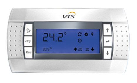
Управляющий пульт HMI Advanced имеет максимально благоприятное соотношение стоимости и функционала. Дистанционный пульт оснащен контрастным дисплеем, который отображает данные от температурных показателях воздуха внутри зданий, а также на основном датчике контроля, о подобранных регламентах функционирования, скоростных режимах вентиляционного комплекса. Кроме того, управляющий пульт показывает текущую дату и время.

Прибор снабжен функцией сигнализирования об аварийных ситуациях с помощью кода, состоящего из букв и цифр. Регулирования вентиляционным комплексом осуществляется специальной кнопкой на основном корпусе. В самой корпусной части, состоящей из крепких полимерных материалов, имеется электронное модульное устройство, оснащенное резистором. Дистанционный пульт управления HMI Advanced VTS имеет защиту, соответствующую требованиям стандартов IР 30 и предназначен работать в интервалах температур -10 — +60 градусов по Цельсию. Электрическое снабжение управляющего пульта совершается прямым образом от щитового устройства постоянного или переменного токов. Обмен информацией с программным логическим контроллером происходит по шине Modbus RTU.
Купить управляющий дистанционный пульт HMI Advanced можно на сайте интернет-магазина FGR. Тут же Вы можете заказать бесплатную доставку по территории России, позвонив по бесплатному номеру телефона 8 (812) 385-56-15.
VTS HMI BASIC 2 HY VENTUS Compact with Heater User Manual

HMI Basic 2 HY is a basic control panel, designed to operate VTS air handling
units equipped with the uPC3 controller.
Panel functions
- AHU starting and stopping
- operating mode selection
- the ability to view and change the parameters of individual operating modes (temperature, humidity, CO2 level, speed of supply and exhaust fans)
- reading of leading, outside and room temperatures (built-in room temperature sensor)
- setting the AHU operation according to the schedule
- alarm handling (viewing, deleting)
Activating the panel in the settings of the AHU controller
The panel is designed for air handling units equipped with the uPC3 controller
with software version 1.0.019 or higher. To enable its support, from the level
of HMI Advanced (physical, connected to the PLAN port of the controller or
virtual, which is part of the visualization application), go to the service
menu and change the last digit of the application code on the I01 screen to 7.
After that, on the J03 screen, set the appropriate Modbus address on the HMI
Basic line (the default HMI Basic 2 HY address is 16) and activate it by
selecting YES.
Connections

Keyboard

Display

The visual indication of the fan operation level (point 22 on the display) is
based on the current control point of the supply fans and is defined as
follows:
If there is no communication with the controller, HMI Basic 2 HY will only
display the current room temperature.
Turning the panel on and off
To turn off the panel screen, hold down the button. Switching on is done by
briefly pressing the same button. Turning off the HMI panel does not mean
turning off the AHU – to turn off the unit, select the Off operating mode.
The display backlight is turned off automatically after a user-defined time.
The backlight is activated by pressing any key. After activating the
backlight, it is possible to perform further operations with the use of the
panel.
Selecting the operating mode
On the main screen, press the button to select the operating mode from among
those visible in the upper part of the screen (Off / StandBy / Eco / Opti /
Comfort / Auto).
Preview of parameters set for the current operating mode
It is possible to check the chosen values for the selected operating mode:
- set temperature
- humidity
- CO2 level
- supply fan speed (S)
- exhaust fan speed (E)
To do this, press ▲▼ on the main screen.
Changing the parameters of individual operating modes
On the main screen, hold down the button, and then by pressing again, select
the mode you are interested in (StandBy / Eco / Opti / Comfort) and confirm
your selection with . We now have the option to set the parameters values
associated with a given mode:
- set temperature
- humidity
- CO2 level
- supply fan speed (S)
- exhaust fan speed (E)
Access to individual settings depends on the AHU configuration and its actual
components.
Changes are done by means of , approval – the button. Exit to the main screen
occurs automatically after a moment of inactivity or after pressing .
Change of the temperature displayed on the main screen
HMI Basic 2 HY enables displaying the current value of one of the three
temperatures on the main screen: · leading, on the basis of which the AHU
operation is carried out (Main)
- external (Ext)
- room (Room)
Switching between them is done by pressing successively on the main screen.
Setting the AHU work schedule
The HMI Basic 2 HY panel is equipped with the possibility of setting and
modifying the AHU work schedule. Changes made from the panel level also affect
the schedule available in HMI Advanced and the visualization – it does not
constitute a separate schedule, but allows full access to the existing one.
On the main screen, hold down the button, and then with successive presses
select the Auto submenu and confirm the selection with button.
- Timer – daily schedule that allows you to program up to 4 mode changes each day at a selected time, separately for each day of the week. We select respectively: the day of the week, activation (On / Off) of individual actions, the time at which the action is to be performed and the mode to be set. By confirming the next parameters, we proceed to the parameterization of the next action (digits 1-4 displayed on the right side of the screen determine which of them are currently being set).
- P – periodic schedule, enabling the selection of up to 3 periods of the year in which the AHU is to operate in the selected mode (this type of schedule has higher priority than the daily schedule). We select respectively: activation (On / Off) of individual periods, date of their end and beginning and the mode to be set. By confirming the next parameters, we proceed to the parameterization of the next period (digits 1-3 displayed on the right side of the screen determine which of them are currently being set).
- S – special schedule that allows to select up to 6 special days a year in which the AHU is to operate in the selected mode (this type of schedule has priority higher than the daily and periodic schedule). We select respectively: activation (On / Off) of a particular special day, its date and mode to be set. By confirming the next parameters, we proceed to the parameterization of the next special day (digits 1-6 displayed on the right side of the screen determine which of them are currently being set).
- T – unused Changes are done by means of , approval – button. Return to the previous menu – . Exit to the main screen occurs automatically after a moment of inactivity or after pressing .
Alarm handling
HMI Basic 2 HY allows to view and delete active alarms. When an alarm is
present, the bell symbol is displayed on the screen and the alarm number is
displayed in place of the current time.
Deleting an alarm, after removing its causes, is done by holding down the
button.
Setting the clock and calendar of the uPC3 controller
On the main screen, hold down the button, and then confirm entering the Set
Day submenu with . This way we will go to the setting of, respectively:
current time, day of the week, month, day and year.
Changes are done by means of , approval – the button. Exit to the main screen
occurs automatically after a moment of inactivity or after pressing .
Programming mode
When the display is turned off by holding down the button, hold down the
button to enter the programming mode (change of advanced parameters).
Successive presses of the button switch between parameters, and use of set
their value. Exit from the menu occurs automatically after a moment of
inactivity or by pressing .

Assembly diagram

Specification

Read User Manual Online (PDF format)
Read User Manual Online (PDF format) >>
Download This Manual (PDF format)
Download this manual >>