
Поскольку в большинстве применений нагрузки постоянно колеблются и непредсказуемы, автоматический регулятор напряжения отвечает за обеспечение гибкости и отзывчивости необходимых вашему генератору, что позволяет ему быстро реагировать и адаптироваться к воздействию нагрузки на всех этапах его работы.
Плохое, нестабильное или ненадежное напряжение от генератора могут привести к простою, потере производительности, потере в комфорте, угрозе безопасности и повреждению оборудования. Покупка оригинального SX460 AVR обеспечит надежную защиту вашего персонала, вашего электронного чувствительного оборудования и, в конечном счете, вашего бизнеса.
ТЕХНИЧЕСКИЕ ХАРАКТЕРИСТИКИ:
Вход
Напряжение выбирается перемычкой: 95-132 В переменного тока или 190-264В переменного тока
Частота: 50-60Гц
Фаза: 1
Выход
Максимальное напряжение: 90 В постоянного тока, при 207 В переменного тока на входе
Постоянный ток: 4 А постоянного тока
Максимальный ток: 6 А в течение 10 секунд
Сопротивление: не менее 15 Ом
Регулирование
+/- 1,0 % (см. примечание 1)
ТЕПЛОВОЙ ДРЕЙФ
0,05% на град. C изменение окружающей среды AVR
ТИПИЧНЫЙ ОТВЕТ СИСТЕМЫ
Отклик AVR 20 мс
Поданный ток до 90% 80 мс
Машинные вольты до 97% 300 мс
ВНЕШНЯЯ РЕГУЛИРОВКА НАПРЯЖЕНИЯ
+/-10% с триммером 1 к Ом 1 Вт
ЗАЩИТА ПО ЧАСТОТЕ
Заданное значение 95 % Гц (см. примечание 4)
Наклон 170% до 30 Гц
РАССЕИВАЕМАЯ МОЩНОСТЬ БЛОКА
Максимум 10 Вт
ОСТАТОЧНОЕ НАПРЯЖЕНИЕ
4 Вольта @ клеммы AVR
Общие
-
Название для сайта
SX460 AVR Регулятор напряжения
Адрес склада и офиса
Режим работы
Наличие
Свердловская область, Белоярский район, поселок Прохладный, Весовая ул., д. 4 (Склад Екатеринбург)
с 9:00 до 17:00 (Пн-Пт)
Москва, 1-я Фрезерная улица, 2/1с1
с 09:00 до 18:00 (Пн-Пт)
Казань, ул Хади Такташа, 131к2
По согласованию
Регулятор напряжения для генератора (SX460) Вес=0,31 кг,размеры в упаковке 15х11,5х5,0 см. маркировка E000-24600, Размеры платы-136х102 мм
Данный регулятор напряжения входит в стандартную комплектацию следующих моделей генераторов:
Генераторы производства Stamford:
BCA162 и BCI162, одноподшипниковые, двухполюсные;
BCA162 и BCI162, двухподшипниковые, двухполюсные;
BCA164 и BCI164, одноподшипниковые четырехполюсные;
BCA164 и BCI164 (модификации от А до Е), двухподшипниковые, четырехполюсные;
BCL164 и BCL184A (модификации от A до F), одноподшипниковые, четырехполюсные;
BCA182 и BCI182 (модификации от Н до К), одноподшипниковые, двухполюсные;
BCA182 и BCI182 (модификации от Н до К), двухподшипниковые, двухполюсные;
BCI184, одноподшипниковые, четырехполюсные;
BCI184, двухподшипниковые, четырехполюсные;
UCD22-27, одноподшипниковые, четырехполюсные;
UC122-1, одноподшипниковые;
UCI224 (модификации от C до G) двухподшипниковые, четырехполюсные;
UCI274 (модификации от C до H), двухподшипниковые, четырехполюсные.
Генераторы производства Fuan Longkai Power Co. Ltd.:
ZC164A, ZC164B, ZC164C, ZC164D, ZC184E, ZC184F, ZC184G, ZC184H, ZC184J, ZC224C, ZC224D, ZC224E, ZC224F, ZC224G, ZC274C, ZC274D, ZC274E, ZC274F, ZC274G, ZC274H, ZC274J, ZC274K.
Генераторы производства Fujian Bobig Electric Machinery Co.,Ltd.:
BW-164A, BW-164B, BW-164C, BW-164D, BW-184E, BW-184F, BW-184G, BW-184H, BW-224C, BW-224D, BW-224E, BW-224F, BW-224G, BW-274C, BW-274DS, BW-274D, BW-274E, BW-274FS, BW-274F, BW-274G, BW-274H, BW-274J, BW-274K.
Важно — Производитель оставляет за собой право без предварительного уведомления покупателя вносить изменения в конструкцию, комплектацию или технологию изготовления изделия. Обязательно уточняйте при оформлении заказа соответствие характеристик приобретаемого оборудования, т.к. данные на нашем сайте могут обновляться с задержкой относительно выпускаемой продукции.
|
Дополнительное оборудование |

TD_SX460.GB_04.05_05_GB
SX460 AUTOMATIC VOLTAGE
REGULATOR (AVR)
SPECIFICATION, INSTALLATION AND ADJUSTMENTS
General description
Technical specification
SX460 is a half-wave phase-controlled thyristor type
Automatic Voltage Regulator (AVR) and forms part of the
excitation system for a brush-less generator.
In addition to regulating the generator voltage, the AVR
circuitry includes under-speed and sensing loss protection
features. Excitation power is derived directly from the
generator terminals.
Positive voltage build up from residual levels is ensured by
the use of efficient semiconductors in the power circuitry of
the AVR.
The AVR is linked with the main stator windings and the
exciter field windings to provide closed loop control of the
output voltage with load regulation of +/- 1.0%.
In addition to being powered from the main stator, the AVR
also derives a sample voltage from the output windings for
voltage control purposes. In response to this sample
voltage, the AVR controls the power fed to the exciter field,
and hence the main field, to maintain the machine output
voltage within the specified limits, compensating for load,
speed, temperature and power factor of the generator.
A frequency measuring circuit continually monitors the
generator output and provides output under-speed
protection of the excitation system, by reducing the output
voltage proportionally with speed below a pre-settable
threshold. A manual adjustment is provided for factory
setting of the under frequency roll off point, (UFRO). This
can easily be changed to 50 or 60 Hz in the field by push-
on link selection.
Provision is made for the connection of a remote voltage
trimmer, allowing the user fine control of the generator’s
output.
INPUT
Voltage
Jumper selectable
95-132V ac or
190-264V
ac
Frequency
50-60 Hz nominal
Voltage
max 90V dc at 207V ac input
Current
continuous 4 A dc
Intermittent 6 A for 10 secs
Resistance
15 ohms minimum
REGULATION
+/- 1.0% (see note 1)
THERMAL DRIFT
0.05% per deg. C change in AVR ambient (note 2)
TYPICAL SYSTEM RESPONSE
AVR response
20 ms
Filed current to 90%
80 ms
Machine Volts to 97%
300 ms
EXTERNAL VOLTAGE ADJUSTMENT
+/-10% with 1 k ohm 1 watt trimmer (see note 3)
UNDER FREQUENCY PROTECTION
Set point
95% Hz (see note 4)
Slope
170% down to 30 Hz
UNIT POWER DISSIPATION
10 watts maximum
BUILD UP VOLTAGE
4 Volts @ AVR terminals
ENVIRONMENTAL
Vibration 20-100
Hz 50mm/sec
100Hz – 2kHz
3.3g
Operating temperature
-40 to +70°C
Relative Humidity 0-70°C
95% (see note 5)
Storage temperature
-55 to +80°C
NOTES
1.
With 4% engine governing
2.
After 10 minutes.
3.
Applies to Mod status F onwards. Generator de-rate may
apply. Check with factory.
4.
Factory set, semi-sealed, jumper selectable
5. Non
condensing.

SX460 AUTOMATIC VOLTAGE
REGULATOR (AVR)
SPECIFICATION, INSTALLATION AND ADJUSTMENTS
General description
SX460 is a half-wave phase-controlled thyristor type
Automatic Voltage Regulator (AVR) and forms part of the
excitation system for a brush-less generator.
In addition to regulating the generator voltage, the AVR
circuitry includes under-speed and sensing loss protection
features. Excitation power is derived directly from the
generator terminals.
Positive voltage build up from residual levels is ensured by
the use of efficient semiconductors in the power circuitry of
the AVR.
The AVR is linked with the main stator windings and the
exciter field windings to provide closed loop control of the
output voltage with load regulation of +/- 1.0%.
In addition to being powered from the main stator, the AVR
also derives a sample voltage from the output windings for
voltage control purposes. In response to this sample
voltage, the AVR controls the power fed to the exciter field,
and hence the main field, to maintain the machine output
voltage within the specified limits, compensating for load,
speed, temperature and power factor of the generator.
A frequency measuring circuit continually monitors the
generator output and provides output under-speed
protection of the excitation system, by reducing the output
voltage proportionally with speed below a pre-settable
threshold. A manual adjustment is provided for factory
setting of the under frequency roll off point, (UFRO). This
can easily be changed to 50 or 60 Hz in the field by pushon link selection.
Provision is made for the connection of a remote voltage
trimmer, allowing the user fine control of the generator’s
output.
Technical specification
INPUT
Voltage Jumper selectable
95-132V ac or
190-264V ac
Frequency 50-60 Hz nominal
Phase 1
OUTPUT
Voltage max 90V dc at 207V ac input
Current continuous 4 A dc
Intermittent 6 A for 10 secs
Resistance 15 ohms minimum
REGULATION
+/- 1.0% (see note 1)
THERMAL DRIFT
0.05% per deg. C change in AVR ambient (note 2)
TYPICAL SYSTEM RESPONSE
AVR response 20 ms
Filed current to 90% 80 ms
Machine Volts to 97% 300 ms
EXTERNAL VOLTAGE ADJUSTMENT
+/-10% with 1 k ohm 1 watt trimmer (see note 3)
UNDER FREQUENCY PROTECTION
Set point 95% Hz (see note 4)
Slope 170% down to 30 Hz
UNIT POWER DISSIPATION
10 watts maximum
BUILD UP VOLTAGE
4 Volts @ AVR terminals
ENVIRONMENTAL
Vibration 20-100 Hz 50mm/sec
100Hz – 2kHz 3.3g
Operating temperature -40 to +70°C
Relative Humidity 0-70°C 95% (see note 5)
Storage temperature -55 to +80°C
NOTES
1. With 4% engine governing
2. After 10 minutes.
3. Applies to Mod status F onwards. Generator de-rate may
apply. Check with factory.
4. Factory set, semi-sealed, jumper selectable
5. Non condensing.
TD_SX460.GB_04.05_05_GB
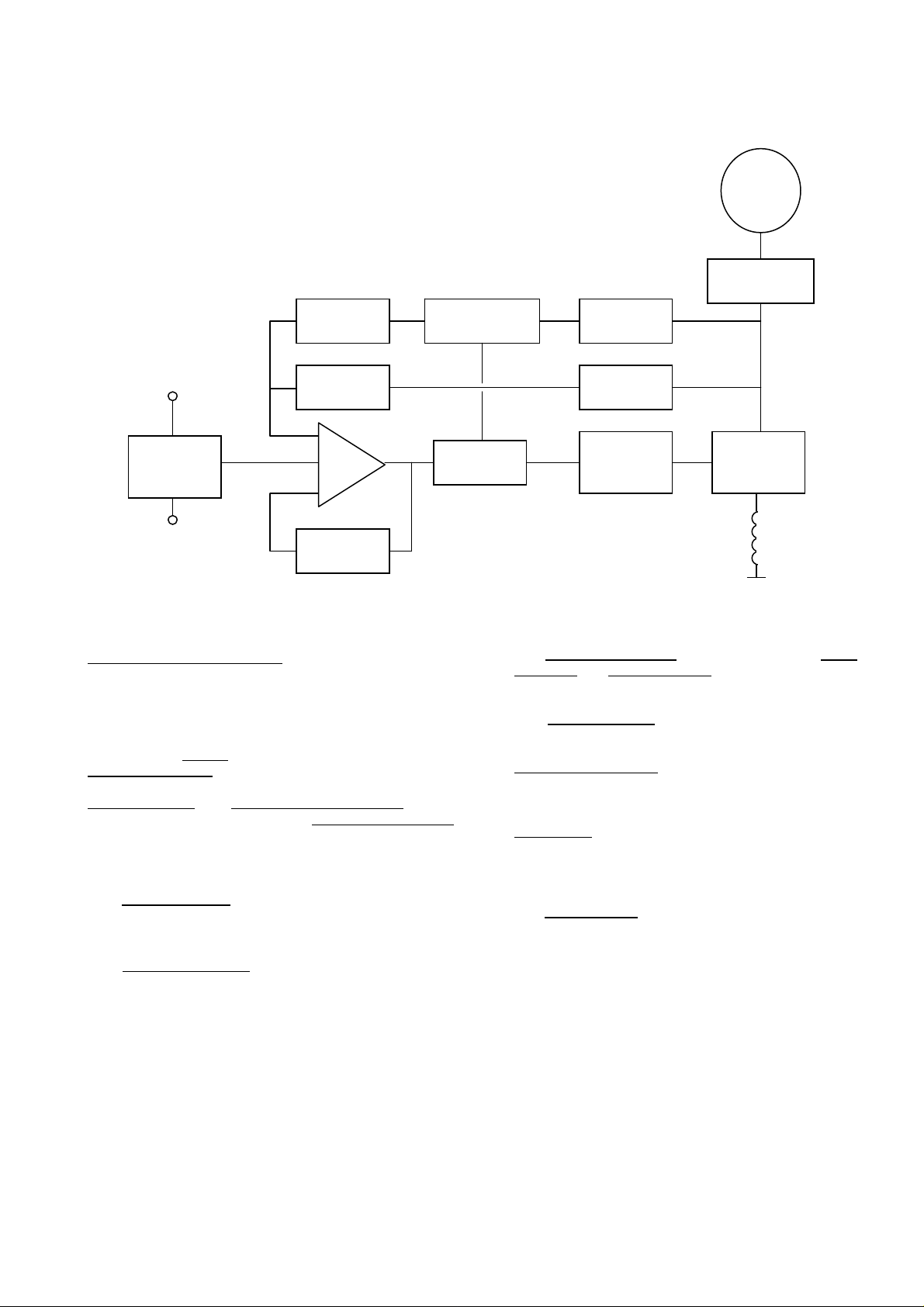
DESIGN DETAIL
Generator
Suppression
Low Hz
Detection
Voltage
Sensing
Potential
Divider &
Rectifier
Hand
Trimmer
The main functions of the AVR are:
Potential Divider and Rectifier
generator output voltage and attenuates it. This input chain
of resistors includes the range potentiometer and hand
trimmer which adjust the generator voltage. A rectifier
converts the a.c. into d.c. for further processing.
The Amplifier (Amp) c
Reference Voltage
provide a controlling signal for the power devices. The
Ramp Generator
control the conduction period of the Power Control Devices
and hence provides the excitation system with the required
power to maintain the generator voltage within specified
limits.
The Stability Circuit
feedback to ensure good steady state and transient
performance of the control system.
ompares the sensing voltage to the
and amplifies the difference (error) to
and Level Detector and Driver infinitely
provides adjustable negative ac
Reference
Volta
Stability
Circuit
takes a proportion of the
e
Amp
Synchronising
Generato
The Low Hz Detector measures the period of each
electrical cycle and causes the reference voltage to be
reduced approximately linearly with speed below a
presettable threshold. A Light Emitting Diode gives
indication of underspeed running.
Ciruit
Ramp
Low Pass
The Synchronising circuit is used to keep the Ramp
Generator and Low Hz Detector locked to the generator
waveform period.
The Low Pass Filter
affecting the operation of the AVR.
Power Control Devices
current in response to the error signal produced by the
Amplifier.
Suppression
cycle voltage spikes damaging the AVR components
and also to reduce the amount of conducted noise on
the generator terminals.
The Power Supply
the AVR circuitry.
Filte
Power
suppl
Level
Detector &
Driver
prevents distorted waveforms
Power
Control
Devices
Exciter
Field
vary the amount of exciter field
components are included to prevent sub
provides the required voltages for
TD_SX460.GB_04.05_05_GB