

HTR-5930
AV Receive r
U
OWNER’S MANUAL
IMPORTANT SAFETY INSTRUCTIONS
IMPORTANT SAFETY INSTRUCTIONS
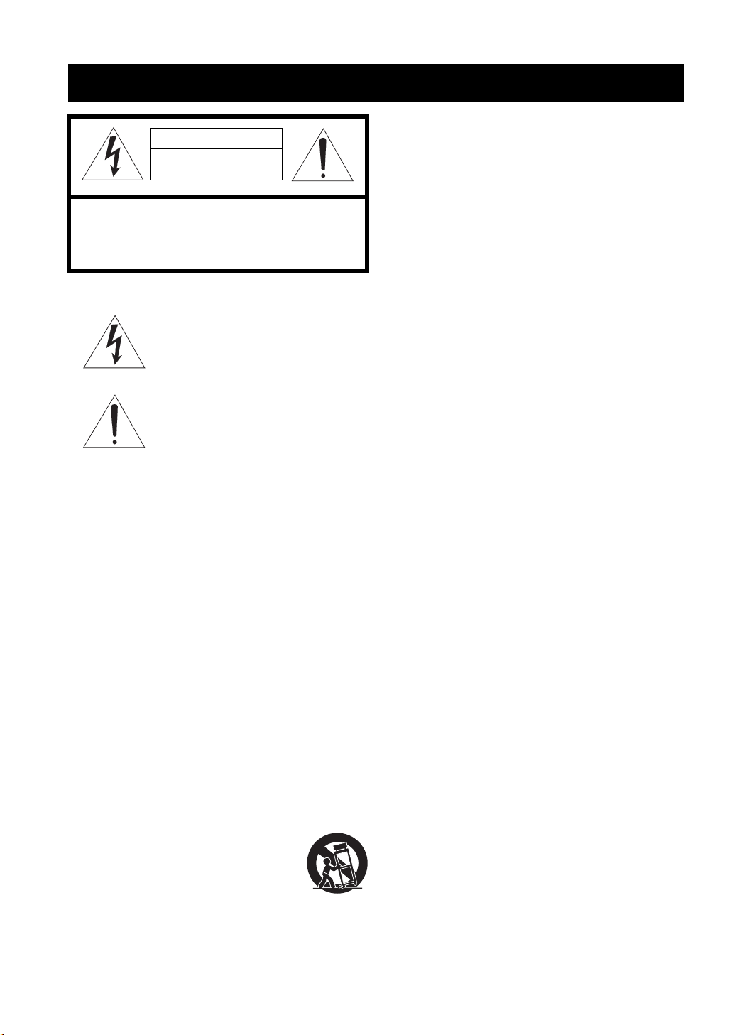
CAUTION
RISK OF ELECTRIC SHOCK
DO NOT OPEN
CAUTION: TO REDUCE THE RISK OF
ELECTRIC SHOCK, DO NOT REMOVE
COVER (OR BACK). NO USER-SERVICEABLE
PARTS INSIDE. REFER SERVICING TO
QUALIFIED SERVICE PERSONNEL.
• Explanation of Graphical Symbols
The lightning flash with arrowhead symbol, within an
equilateral triangle, is intended to alert you to the
presence of uninsulated “dangerous voltage” within
the product’s enclosure that may be of sufficient
magnitude to constitute a risk of electric shock to
persons.
The exclamation point within an equilateral triangle
is intended to alert you to the presence of important
operating and maintenance (servicing) instructions in
the literature accompanying the appliance.
1 Read Instructions – All the safety and operating instructions
should be read before the product is operated.
2 Retain Instructions – The safety and operating instructions
should be retained for future reference.
3 Heed Warnings – All warnings on the product and in the
operating instructions should be adhered to.
4 Follow Instructions – All operating and use instructions
should be followed.
5 Cleaning – Unplug this product from the wall outlet before
cleaning. Do not use liquid cleaners or aerosol cleaners.
6 Attachments – Do not use attachments not recommended by
the product manufacturer as they may cause hazards.
7 Water and Moisture – Do not use this product near water –
for example, near a bath tub, wash bowl, kitchen sink, or
laundry tub; in a wet basement; or near a swimming pool;
and the like.
8 Accessories – Do not place this product on an unstable cart,
stand, tripod, bracket, or table. The product may fall,
causing serious injury to a child or adult, and serious
damage to the product. Use only with a cart, stand, tripod,
bracket, or table recommended by the manufacturer, or sold
with the product. Any mounting of the product should
follow the manufacturer’s instructions, and should use a
mounting accessory recommended by the manufacturer.
9 A product and cart combination should be moved with care.
Quick stops, excessive force, and uneven surfaces may
cause the product and cart combination to
overturn.
10 Ventilation – Slots and openings in the cabinet are provided
for ventilation and to ensure reliable operation of the
product and to protect it from overheating, and these
openings must not be blocked or covered. The openings
should never be blocked by placing the product on a bed,
sofa, rug, or other similar surface. This product should not
be placed in a built-in installation such as a bookcase or rack
unless proper ventilation is provided or the manufacturer’s
instructions have been adhered to.
11 Power Sources – This product should be operated only from
the type of power source indicated on the marking label. If
you are not sure of the type of power supply to your home,
consult your product dealer or local power company. For
products intended to operate from battery power, or other
sources, refer to the operating instructions.
12 Grounding or Polarization – This product may be equipped
with a polarized alternating current line plug (a plug having
one blade wider than the other). This plug will fit into the
power outlet only one way. This is a safety feature. If you
are unable to insert the plug fully into the outlet, try
reversing the plug. If the plug should still fail to fit, contact
your electrician to replace your obsolete outlet. Do not
defeat the safety purpose of the polarized plug.
13 Power-Cord Protection – Power-supply cords should be
routed so that they are not likely to be walked on or pinched
by items placed upon or against them, paying particular
attention to cords at plugs, convenience receptacles, and the
point where they exit from the product.
14 Lightning – For added protection for this product during a
lightning storm, or when it is left unattended and unused for
long periods of time, unplug it from the wall outlet and
disconnect the antenna or cable system. This will prevent
damage to the product due to lightning and power-line
surges.
15 Power Lines – An outside antenna system should not be
located in the vicinity of overhead power lines or other
electric light or power circuits, or where it can fall into such
power lines or circuits. When installing an outside antenna
system, extreme care should be taken to keep from touching
such power lines or circuits as contact with them might be
fatal.
16 Overloading – Do not overload wall outlets, extension
cords, or integral convenience receptacles as this can result
in a risk of fire or electric shock.
17 Object and Liquid Entry – Never push objects of any kind
into this product through openings as they may touch
dangerous voltage points or short-out parts that could result
in a fire or electric shock. Never spill liquid of any kind on
the product.
18 Servicing – Do not attempt to service this product yourself
as opening or removing covers may expose you to
dangerous voltage or other hazards. Refer all servicing to
qualified service personnel.
19 Damage Requiring Service – Unplug this product from the
wall outlet and refer servicing to qualified service personnel
under the following conditions:
a) When the power-supply cord or plug is damaged,
b) If liquid has been spilled, or objects have fallen into the
product,
c) If the product has been exposed to rain or water,
i
IMPORTANT SAFETY INSTRUCTIONS
d) If the product does not operate normally by following
the operating instructions. Adjust only those controls
that are covered by the operating instructions as an
improper adjustment of other controls may result in
damage and will often require extensive work by a
qualified technician to restore the product to its normal
operation,
e) If the product has been dropped or damaged in any
way, and
f) When the product exhibits a distinct change in perfor-
mance — this indicates a need for service.
20 Replacement Parts – When replacement parts are required,
be sure the service technician has used replacement parts
specified by the manufacturer or have the same
characteristics as the original part. Unauthorized
substitutions may result in fire, electric shock, or other
hazards.
21 Safety Check – Upon completion of any service or repairs to
this product, ask the service technician to perform safety
checks to determine that the product is in proper operating
condition.
22 Wall or Ceiling Mounting – The unit should be mounted
to a wall or ceiling only as recommended by the
manufacturer.
23 Heat – The product should be situated away from heat
sources such as radiators, heat registers, stoves, or other
products (including amplifiers) that produce heat.
Note to CATV system installer:
This reminder is provided to call the CATV system installer’s
attention to Article 820-40 of the NEC that provides
guidelines for proper grounding and, in particular, specifies
that the cable ground shall be connected to the grounding
system of the building, as close to the point of cable entry as
practical.
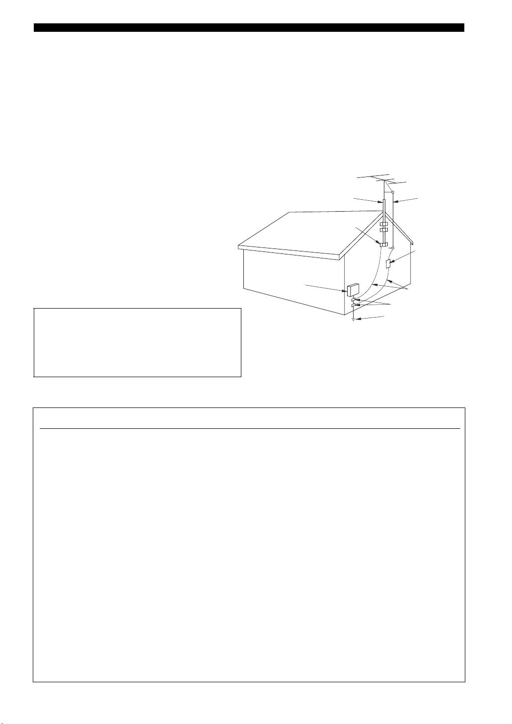
24 Outdoor Antenna Grounding – If an outside antenna or
cable system is connected to the product, be sure the antenna
or cable system is grounded so as to provide some
protection against voltage surges and built-up static charges.
Article 810 of the National Electrical Code, ANSI/NFPA 70,
provides information with regard to proper grounding of the
mast and supporting structure, grounding of the lead-in wire
to an antenna discharge unit, size of grounding conductors,
location of antenna discharge unit, connection to grounding
electrodes, and requirements for the grounding electrode.
EXAMPLE OF ANTENNA GROUNDING
ANTENNA
LEAD IN
WIRE
ANTENNA
DISCHARGE UNIT
(NEC SECTION 810–20)
GROUNDING CONDUCTORS
(NEC SECTION 810–21)
GROUND CLAMPS
ELECTRIC
SERVICE
EQUIPMENT
NEC – NATIONAL ELECTRICAL CODE
MAST
GROUND
CLAMP
POWER SERVICE GROUNDING
ELECTRODE SYSTEM
(NEC ART 250. PART H)
FCC INFORMATION (for US customers)
1 IMPORTANT NOTICE: DO NOT MODIFY THIS
UNIT!
This product, when installed as indicated in the
instructions contained in this manual, meets FCC
requirements. Modifications not expressly approved by
Yamaha may void your authority, granted by the FCC, to
use the product.
2 IMPORTANT: When connecting this product to
accessories and/or another product use only high quality
shielded cables. Cable/s supplied with this product MUST
be used. Follow all installation instructions. Failure to
follow instructions could void your FCC authorization to
use this product in the USA.
3 NOTE: This product has been tested and found to comply
with the requirements listed in FCC Regulations, Part 15
for Class “B” digital devices. Compliance with these
requirements provides a reasonable level of assurance that
your use of this product in a residential environment will
not result in harmful interference with other electronic
devices.
This equipment generates/uses radio frequencies and, if
not installed and used according to the instructions found
in the users manual, may cause interference harmful to the
operation of other electronic devices.
Compliance with FCC regulations does not guarantee that
interference will not occur in all installations. If this
product is found to be the source of interference, which
can be determined by turning the unit “OFF” and “ON”,
please try to eliminate the problem by using one of the
following measures:
Relocate either this product or the device that is being
affected by the interference.
Utilize power outlets that are on different branch (circuit
breaker or fuse) circuits or install AC line filter/s.
In the case of radio or TV interference, relocate/reorient
the antenna. If the antenna lead-in is 300 ohm ribbon lead,
change the lead-in to coaxial type cable.
If these corrective measures do not produce satisfactory
results, please contact the local retailer authorized to
distribute this type of product. If you can not locate the
appropriate retailer, please contact Yamaha Electronics
Corp., U.S.A. 6660 Orangethorpe Ave, Buena Park, CA
90620.
The above statements apply ONLY to those products
distributed by Yamaha Corporation of America or its
subsidiaries.
ii
CAUTION: READ THIS BEFORE OPERATING YOUR UNIT.
CAUTION: READ THIS BEFORE OPERATING YOUR UNIT.
1 To assure the finest performance, please read this
manual carefully. Keep it in a safe place for future
reference.
2 Install this sound system in a well ventilated, cool,
dry, clean place – away from direct sunlight, heat
sources, vibration, dust, moisture, and/or cold.
Allow ventilation space of at least 30 cm on the top,
20 cm on the left and right, and 20 cm on the back of
this unit.
3 Locate this unit away from other electrical
appliances, motors, or transformers to avoid
humming sounds.
4 Do not expose this unit to sudden temperature
changes from cold to hot, and do not locate this unit
in a environment with high humidity (i.e. a room with
a humidifier) to prevent condensation inside this
unit, which may cause an electrical shock, fire,
damage to this unit, and/or personal injury.
5 Avoid installing this unit where foreign object may
fall onto this unit and/or this unit may be exposed to
liquid dripping or splashing. On the top of this unit,
do not place:
– Other components, as they may cause damage
and/or discoloration on the surface of this unit.
– Burning objects (i.e. candles), as they may cause
fire, damage to this unit, and/or personal injury.
– Containers with liquid in them, as they may fall
and liquid may cause electrical shock to the user
and/or damage to this unit.
6 Do not cover this unit with a newspaper, tablecloth,
curtain, etc. in order not to obstruct heat radiation. If
the temperature inside this unit rises, it may cause
fire, damage to this unit, and/or personal injury.
7 Do not plug in this unit to a wall outlet until all
connections are complete.
8 Do not operate this unit upside-down. It may
overheat, possibly causing damage.
9 Do not use force on switches, knobs and/or cords.
10 When disconnecting the power cable from the wall
outlet, grasp the plug; do not pull the cord.
11 Do not clean this unit with chemical solvents; this
might damage the finish. Use a clean, dry cloth.
12 Only voltage specified on this unit must be used.
Using this unit with a higher voltage than specified
is dangerous and may cause fire, damage to this
unit, and/or personal injury. YAMAHA will not be
held responsible for any damage resulting from use
of this unit with a voltage other than specified.
13 To prevent damage by lightning, keep the power
cord and outdoor antennas disconnected from a
wall outlet or the unit during a lightning storm.
14 Do not attempt to modify or fix this unit. Contact
qualified YAMAHA service personnel when any
service is needed. The cabinet should never be
opened for any reasons.
15 When not planning to use this unit for long periods
of time (i.e. vacation), disconnect the AC power plug
from the wall outlet.
16 Install this unit near the AC outlet and where the AC
power plug can be reached easily.
17 Be sure to read the “TROUBLESHOOTING” section
on common operating errors before concluding that
this unit is faulty.
18 Before moving this unit, press STANDBY/ON to set
this unit in the standby mode, and disconnect the
AC power plug from the wall outlet.
19 VOLTAGE SELECTOR (Asia and General models
only)
The VOLTAGE SELECTOR on the rear panel of this
unit must be set for your local main voltage BEFORE
plugging into the AC wall outlet.
Voltages are 110–120/220–240 V AC, 50/60 Hz.
WARNING
TO REDUCE THE RISK OF FIRE OR ELECTRIC
SHOCK, DO NOT EXPOSE THIS UNIT TO RAIN
OR MOISTURE.
This unit is not disconnected from the AC power
source as long as it is connected to the wall outlet, even
if this unit itself is turned off by STANDBY/ON. This
state is called the standby mode. In this state, this unit
is designed to consume a very small quantity of power.
FOR CANADIAN CUSTOMERS
To prevent electric shock, match wide blade of plug to
wide slot and fully insert.
This Class B digital apparatus complies with Canadian
ICES-003.
IMPORTANT
Please record the serial number of this unit in the space
below.
MODEL:
Serial No.:
The serial number is located on the rear of the unit.
Retain this Owner’s Manual in a safe place for future
reference.
We Want You Listening For A Lifetime
YAMAHA and the Electronic Industries Association’s Consumer
Electronics Group want you to get the most out of your
equipment by playing it at a safe level. One that lets the sound
come through loud and clear without annoying blaring or
distortion – and, most importantly, without affecting your
sensitive hearing.
iii
Since hearing damage from loud sounds is often
undetectable until it is too late, YA M A H A and the
Electronic Industries Association’s Consumer
Electronics Group recommend you to avoid
prolonged exposure from excessive volume levels.

CONTENTS
INTRODUCTION
FEATURES……………………………………………………. 2
GETTING STARTED…………………………………….. 3
Supplied accessories ………………………………………….. 3
Installing batteries in the remote control ………………. 3
CONTROLS AND FUNCTIONS ……………………. 4
Front panel ……………………………………………………….. 4
Remote control………………………………………………….. 6
Front panel display ……………………………………………. 8
Rear panel ………………………………………………………… 9
PREPARATION
CONNECTIONS ………………………………………….. 10
Placing speakers………………………………………………. 10
Connecting speakers ………………………………………… 11
Information on jacks and cable plugs …………………. 13
Connecting video components…………………………… 14
Connecting audio components…………………………… 17
Connecting the FM and AM antennas ………………… 18
Connecting the power cable………………………………. 19
Turning on the power……………………………………….. 19
SETUP …………………………………………………………. 20
Using BASIC MENU ………………………………………. 20
BASIC OPERATION
PLAYBACK…………………………………………………. 23
Basic operations………………………………………………. 23
Additional operations……………………………………….. 25
SOUND FIELD PROGRAMS……………………….. 30
Sound field program descriptions ………………………. 31
RECORDING ………………………………………………. 34
FM/AM TUNING …………………………………………. 35
Automatic tuning …………………………………………….. 35
Manual tuning…………………………………………………. 36
Automatic preset tuning……………………………………. 37
Manual preset tuning ……………………………………….. 38
Selecting preset stations……………………………………. 39
Exchanging preset stations ……………………………….. 40
XM® SATELLITE RADIO TUNING …………… 41
What is XM Satellite Radio? …………………………….. 41
Connecting the XM Connect-and-Play
digital antenna …………………………………………….. 41
XM Satellite Radio controls and functions………….. 42
Activating XM Satellite Radio ………………………….. 43
Basic XM Satellite Radio operations………………….. 44
Selecting the XM Satellite Radio search mode …….45
Setting XM Satellite Radio preset channels ………… 49
Displaying the XM Satellite Radio information…… 50
ADVANCED OPERATION
SET MENU ……………………………………………………52
Using SET MENU…………………………………………… 53
SOUND MENU………………………………………………. 53
INPUT MENU………………………………………………… 55
OPTION MENU……………………………………………… 56
REMOTE CONTROL FEATURES ……………….57
Controlling this unit, a TV, or other components…. 57
Setting remote control codes …………………………….. 59
ADDITIONAL INFORMATION
TROUBLESHOOTING …………………………………60
RESETTING THE SYSTEM………………………….65
GLOSSARY…………………………………………………..66
Audio information …………………………………………… 66
Sound field program information ………………………. 67
Video information……………………………………………. 67
SPECIFICATIONS………………………………………..68
PREPARATIONINTRODUCTION
OPERATION
BASIC
OPERATION
ADVANCED
INFORMATION
ADDITIONAL
1
FEATURES
FEATURES
Built-in 5-channel power amplifier
◆ Minimum RMS output power
[U.S.A. and Canada models]
(0.9% THD, 1 kHz, 8 Ω/6 Ω)
Front: 110 W + 110 W
Center: 110 W
Surround: 110 W + 110 W
Sophisticated AM/FM tuner
◆ 40-station random and direct preset tuning
◆ Automatic preset tuning
◆ Preset station shifting capability (preset editing)
XM Satellite Radio (U.S.A. model only)
◆ XM Satellite Radio tuning capability (Using the “XM
Connect-and-Play digital antenna” sold separately)
[Other models]
(0.9% THD, 1 kHz, 6 Ω)
Front: 100 W + 100 W
Center: 100 W
Surround: 100 W + 100 W
Other features
◆ 192-kHz/24-bit D/A converter
◆ 6 additional input jacks for discrete multi-channel input
◆ A SET MENU that allows you to optimize this unit to
suit your individual audiovisual system
Decoders and DSP circuits
◆ Proprietary YAMAHA technology for the creation of
multi-channel surround sound
◆ Dolby Digital decoder
◆ Dolby Pro Logic/Dolby Pro Logic II decoder
◆ DTS decoder
◆ Virtual CINEMA DSP
◆ SILENT CINEMA
• y indicates a tip for your operation.
• Some operations can be performed by using either the buttons on the front panel or the ones on the remote control. In case the button
names differ between the front panel and the remote control, the button name on the remote control is given in parentheses.
• This manual is printed prior to production. Design and specifications are subject to change in part as a result of improvements, etc. In
case of differences between the manual and product, the product has priority.
™
◆ Component video input/output capability
(3 COMPONENT VIDEO INs and 1 MONITOR
OUT)
◆ Optical and coaxial digital audio signal jacks
◆ Sleep timer
◆ Night listening mode
◆ Remote control with preset remote control codes
Manufactured under license from Dolby Laboratories.
“Dolby”, “Pro Logic”, and the double-D symbol are trademarks
of Dolby Laboratories.
“SILENT CINEMA” is a trademark of YAMAHA
CORPORATION.
2
“DTS” and “DTS Digital Surround” are registered trademarks of
Digital Theater Systems, Inc.
The XM name and related logos are registered trademarks of XM
Satellite Radio Inc.
GETTING STARTED
GETTING STARTED
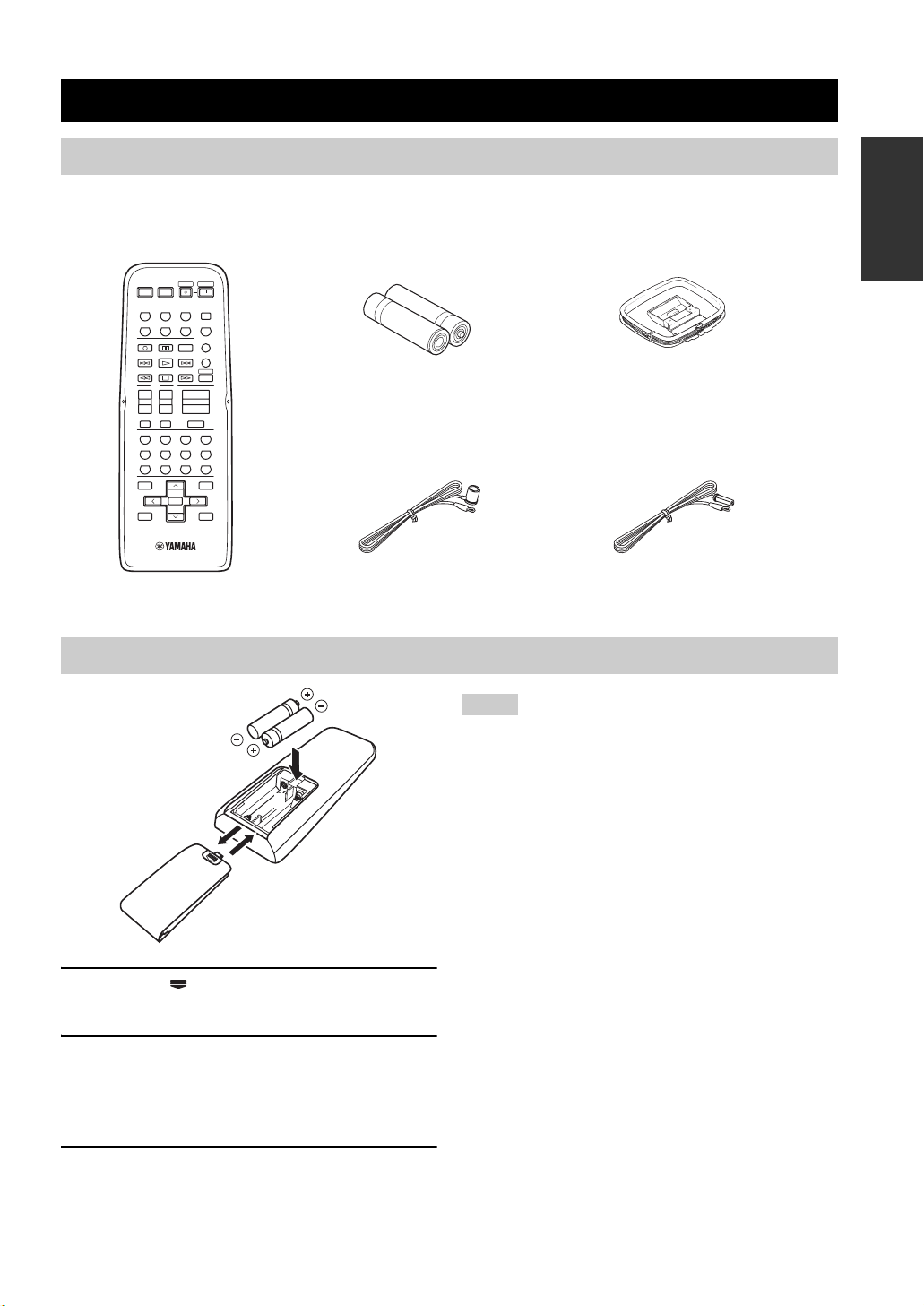
Supplied accessories
Check that you received all of the following parts.
Remote control
POWER
STANDBY
POWERAVPOWERTVPOWER
TV
REC
DISC SKIP
+
–
2CH STEREO
1
A
LEVEL
TITLE
–
TEST
RETURN
MEMORY
TV
SPEAKERS
+–+
CHVOL
INPUTMUTE
B
09
ENTER
PRESET/CH
SLEEP
TUNERMD/CD-RCD
V-AUXVCRDTV/CBLDVD
MULTI CH IN
AUDIO
CODE SET
AMP
VOLUME
–
MUTE
MOVIEENTERTAINMUSIC
432
5CH STEREOSTANDARD
8765
STRAIGHT
NIGHT
ENT.
+10
SET MENU
MENU
SRCH MODEBAND
+
A-E/CAT.
DISPLAY
Batteries (2)
(AA, R06, UM-3)
Indoor FM antenna
(U.S.A., Canada, China, Asia
and General models)
Installing batteries in the remote control
INTRODUCTION
AM loop antenna
Indoor FM antenna
(U.K., Europe, Australia
and Korea models)
2
1
3
1 Press the part and slide the battery
compartment cover off.
2 Insert the two supplied batteries (AA, R06,
UM-3) according to the polarity markings
(+ and –) on the inside of the battery
compartment.
3 Slide the cover back until it snaps into place.
Notes
• Change all of the batteries if you notice a decrease in the
operation range of the remote control.
• Do not use an old battery together with a new one.
• Do not use different types of batteries (such as alkaline and
manganese batteries) together. Read the packaging carefully as
these different types of batteries may have the same shape and
color.
• If the batteries have leaked, dispose of them immediately. Avoid
touching the leaked material or letting it come into contact with
clothing, etc. Clean the battery compartment thoroughly before
installing new batteries.
• Do not throw away batteries with general house waste; dispose
of them correctly in accordance with your local regulations.
• If the remote control is without batteries for more than
2 minutes, or if exhausted batteries remain in the remote
control, the contents of the memory may be cleared. When the
memory is cleared, insert new batteries, set up the remote
control code and program any acquired functions that may have
been cleared.
3
CONTROLS AND FUNCTIONS
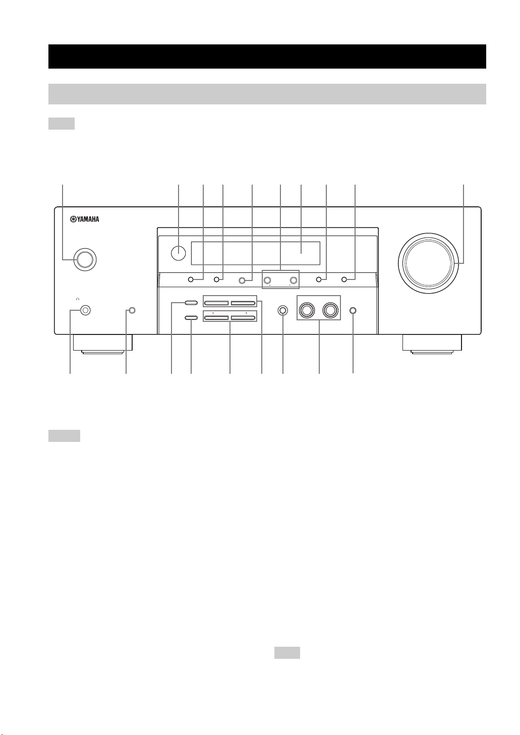
CONTROLS AND FUNCTIONS
Front panel
Note
The XM Satellite Radio controlling functions in the following buttons (SEARCH MODE, XM, CATEGORY, PRESET/TUNING/CH
l / h, MEMORY, and DISPLAY) are only applicable to the U.S.A. model and are operational only when “XM” is selected as the
input source. For details, see “XM Satellite Radio controls and functions” on page 42.
1
STANDBY
/ON
PHONES
SILENT CINEMA
SPEAKERS
A/B/OFF
234 5 67 8 9 0
SEARCH MODE
EDIT
STRAIGHT
EFFECT
TONE CONTROL
FM/AMPRESET/TUNING
A/B/C/D/E
XM
CATEGORY
l PROGRAM h
BASS/TREBLE
NEXT
lh
PRESET/TUNING/CH
SET MENU
INPUT MODE
l INPUT h
MEMORY
TUNING MODE
DISPLAY
AUTO/MAN’LMAN’L/AUTO FM
MULTI CH INPUT
ABCD FEGHI
1 STANDBY/ON
Turns on this unit or sets it to the standby mode.
Notes
• In the standby mode, this unit consumes a small amount of
power in order to receive infrared-signals from the remote
control.
• When you turn on this unit, there will be a 4 to 5-second delay
before this unit can reproduce sound.
2 Remote control sensor
Receives signals from the remote control.
3 PRESET/TUNING
• Switches the function of PRESET/TUNING/CH l / h
between selecting preset station numbers and selecting
the tuning frequency.
• Edits the assignments of present stations.
4 FM/AM
Switches the reception band between FM and AM.
5 A/B/C/D/E
Selects one of the 5 preset station groups (A to E) when
“FM” or “AM” is selected as the input source.
6 PRESET/TUNING/CH l / h
• Selects one of the 8 preset station numbers (1 to 
when “FM” or “AM” is selected as the input source.
The colon (:) is displayed in the front panel display.
• Selects the tuning frequency when “FM” or “AM” is
selected as the input source. The colon (:) is not
displayed in the front panel display.
7 Front panel display
Shows information about the operational status of this unit.
8 MEMORY
Stores a preset station in the memory. Hold down this
button for more than 3 seconds to start automatic preset
tuning.
9 TUNING MODE
Switches between automatic tuning (the AUTO indicator
is turned on) and manual tuning (the AUTO indicator is
turned off).
0 VOLUME
Controls the output level of all audio channels.
Note
This does not affect the AUDIO OUT (REC) level.
VOLUME
(U.S.A. model)
4

A PHONES jack
Outputs audio signals for private listening with
headphones.
Notes
• When you connect headphones, no signals are output at the
SUBWOOFER OUTPUT jack or at the SPEAKERS terminals.
• All Dolby Digital and DTS audio signals are mixed down to the
left and right headphone channels.
B SPEAKERS
Turns on or off the set of front speakers connected to the A
and/or B terminals on the rear panel.
C STRAIGHT
Turns the sound field programs off or on. When this unit is
in the “STRAIGHT” mode, 2-channel or multi-channel
input signals are output directly from their respective
speakers without effect processing.
D TONE CONTROL
Adjusts the bass/treble balance of the front left and right
speakers in conjunction with BASS/TREBLE +/–.
E BASS/TREBLE +/–
Adjusts the bass/treble balance of the front left and right
speakers in conjunction with TONE CONTROL.
F PROGRAM l / h
Selects sound field programs.
G INPUT MODE
Selects either digital or analog input signals exclusively or
sets this unit to automatically detect the type of input
signals and select the corresponding input signals when
one component is connected via both digital and analog
connections.
H INPUT l / h
Selects the desired input source.
I MULTI CH INPUT
Selects the component connected to the MULTI CH
INPUT jacks as the input source.
CONTROLS AND FUNCTIONS
INTRODUCTION
Note
The input source connected to the MULTI CH INPUT jacks takes
priority over the source selected with INPUT l / h on the front
panel (or the input selector buttons on the remote control).
5
CONTROLS AND FUNCTIONS
Remote control
This section describes the function of each control on the
remote control used to control this unit. To operate other
components, see “REMOTE CONTROL FEATURES” on
page 57.
Note
The XM Satellite Radio controlling functions in the following
buttons (BAND, MEMORY, SRCH MODE, DISPLAY, cursor
buttons u / d / j / i, numeric buttons and ENT.) are only
applicable to the U.S.A. model and are operational only when
“XM” is selected as the input source. For details, see “XM
Satellite Radio controls and functions” on page 42.
18
■ Controlling this unit
Press AMP to control this unit.
1 Infrared signal transmitter
Outputs infrared control signals. Aim the transmitter at the
component you want to operate.
2 Input selector buttons
Select the input source you want to control.
3 Sound field program selector buttons
Select sound field programs.
4 SPEAKERS A/B
Turn on or off the set of front speakers connected to the A
and/or B terminals on the rear panel.
5 LEVEL
Selects the speaker channel to be adjusted.
6 Cursor buttons u / d / j / i
Select and adjust sound field program parameters or SET
MENU items.
7 TEST
Outputs the test tone to adjust the speaker levels.
8 STANDBY
Sets this unit to the standby mode.
9 POWER
Turns on this unit.
0 SLEEP
Sets the sleep timer.
A MULTI CH IN
Selects the component connected to the MULTI CH
INPUT jacks as the input source when using an external
decoder, etc.
B CODE SET
Use to set up remote control codes.
C AMP
Sets the remote control to the operation mode of this unit.
D VOLUME +/–
Controls the output level of all audio channels.
2
3
4
5
6
7
POWERTVPOWER
TV
REC
DISC SKIP
TV
+
–
2CH STEREO
1
SPEAKERS
A
LEVEL
TITLE
–
TEST
RETURN
MEMORY
POWER
AV
+
CHVO L
–
INPUTMUTE
B
09
STANDBY
TUNERMD/CD-RCD
5CH STEREOSTANDARD
NIGHT
ENTER
PRESET/CH
AUDIO
VOLU ME
+10
MULTI CH IN
+
–
MUTE
STRAIGHT
SRCH MODEBAND
A-E/CAT.
POWER
SLEEP
V-AU XVCRDTV/CBLDVD
CODE SET
AMP
MOVIEENTERTAINMUSIC
432
8765
ENT.
SET MENU
MENU
+
DISPLAY
9
0
A
B
C
D
E
F
G
H
Note
This does not affect the AUDIO OUT (REC) level.
(U.S.A. model)
6
CONTROLS AND FUNCTIONS
E MUTE
Mutes the audio output. Press again to restore the audio
output to the previous volume level.
F STRAIGHT
Turns the sound field programs off or on. When this unit is
in the “STRAIGHT” mode, 2-channel or multi-channel
input signals are output directly from their respective
speakers without effect processing.
G NIGHT
Turns on or off the night listening mode.
H SET MENU
Enters “SET MENU”.
■ Controlling the TUNER functions
To control the TUNER function, press TUNER and then
BAND repeatedly to select “FM” or “AM” as the input
source.
3 Numeric buttons
Select preset stations.
5 BAND
Switches the reception band between “FM” and “AM”.
6 A-E/CAT. j / i, PRESET/CH u / d
Press A-E/CAT. j / i to select a preset station group (A to
E) and PRESET/CH u / d to select a preset station
number (1 to 8).
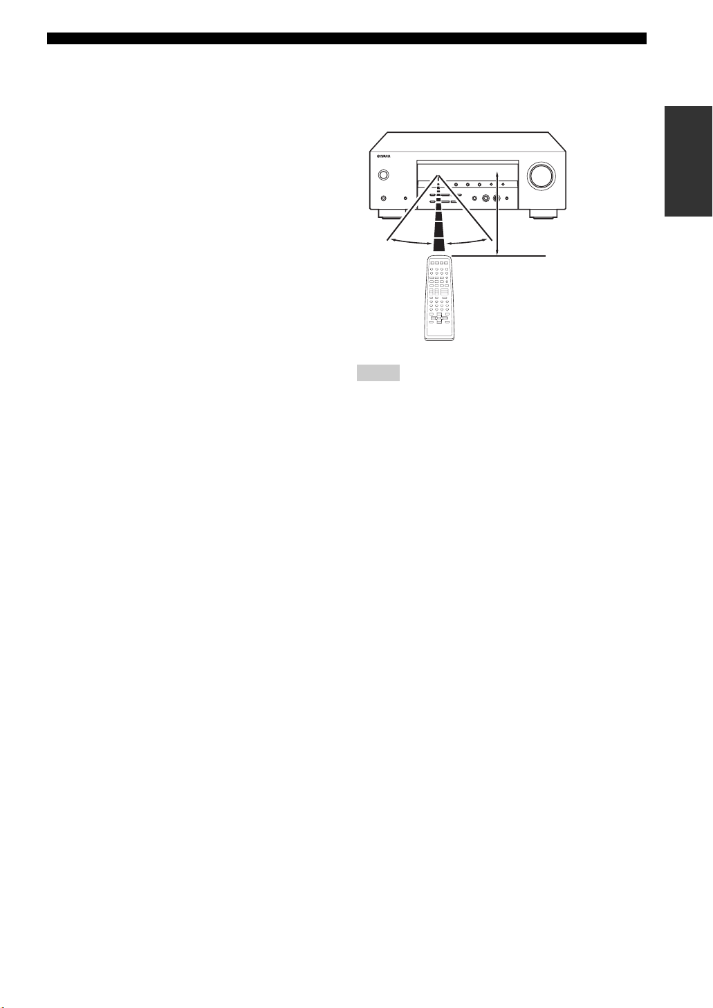
■ Using the remote control
The remote control transmits a directional infrared ray.
Be sure to aim the remote control directly at the remote
control sensor on this unit during operation.
30º 30º
Notes
• Do not spill water or other liquids on the remote control.
• Do not drop the remote control.
• Do not leave or store the remote control in the following types
of conditions:
– places of high humidity, such as near a bath
– places of high temperature, such as near a heater or stove
– places of extremely low temperatures
– dusty places
Approximately 6 m (20 ft)
INTRODUCTION
7
CONTROLS AND FUNCTIONS
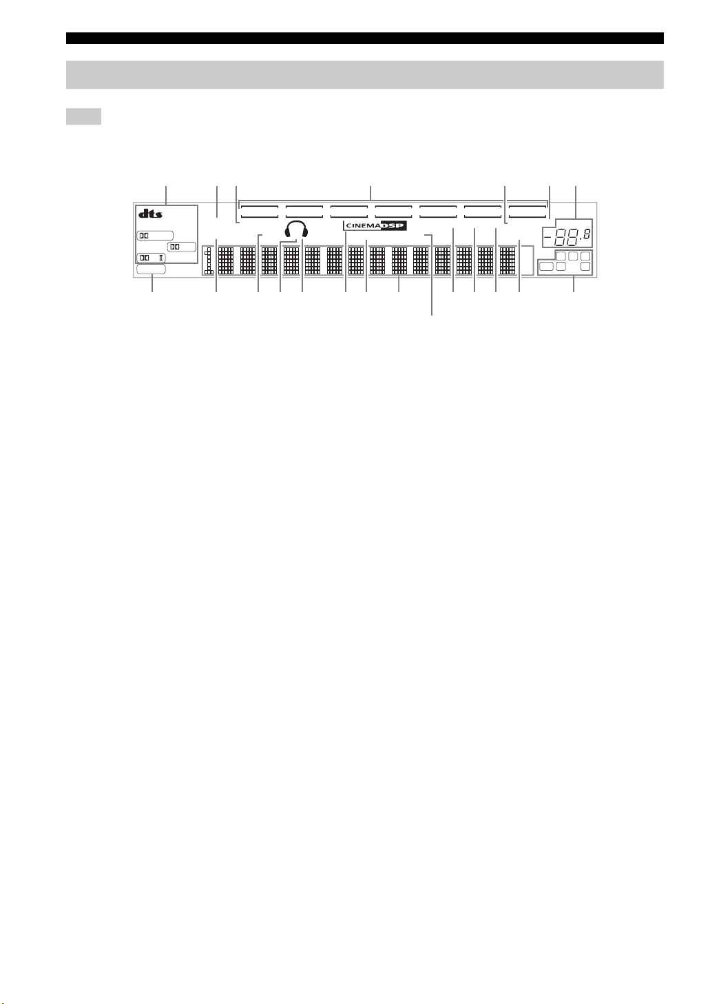
Front panel display
Note
The XM indicator is only applicable to the U.S.A. model and lights up only when “XM” is selected as the input source. For details, see
“Basic XM Satellite Radio operations” on page 44.
312 4 5 76
VCR
PCM
DIGITAL
PL
VIRTUAL
STANDARD NIGHT
PL
SILENT CINEMA
V-A UX
SP
AB
DTV/CBL
HiFi DSP
DVD
MD/CD-R
XM
TUNER CD
AUTO
TUNED
STEREO
MEMORY
SLEEP
dB
MUTE
ft
LFE SL SR
VOLUME
dB
LCR
890ACBDKFGHI J
1 Decoder indicators
The respective indicator lights up when any of the
decoders of this unit function.
2 VIRTUAL indicator
Lights up when Virtual CINEMA DSP is active.
3 SILENT CINEMA indicator
Lights up when headphones are connected and a sound
field program is selected.
4 Input source indicators
A corresponding cursor lights up to show the currently
selected input source.
5 MEMORY indicator
Flashes to show that a station can be stored.
6 MUTE indicator
Flashes while the MUTE function is on.
7 VOLUME level indicator
Indicates the current volume level.
8 PCM indicator
Lights up when this unit is reproducing PCM (Pulse Code
Modulation) digital audio signals.
9 STANDARD indicator
Lights up when the “STANDARD” program is selected.
E
(U.S.A. model only)
C CINEMA DSP indicator
Lights up when you select a CINEMA DSP program.
D HiFi DSP indicator
Lights up when you select a HiFi DSP program.
E Multi-information display
Shows the name of the current program and other
information when adjusting or changing settings.
F AUTO indicator
Lights up when this unit is in the automatic tuning mode.
G TUNED indicator
Lights up when this unit is tuned into a station.
H STEREO indicator
Lights up when this unit is receiving a strong signal for an
FM stereo broadcast while the AUTO indicator is lit.
I SLEEP indicator
Lights up while the sleep timer is on.
J Input channel indicators
Indicate the channel components of the current digital
input signal.
K XM indicator
Lights up when “XM” is selected as the input source.
0 NIGHT indicator
Lights up when you select a night listening mode.
A Speaker indicators
Light up according to the set of front speakers selected.
B Headphones indicator
Lights up when headphones are connected.
8
Loading…
Скачать
HTR-5930
AV Receiver
OWNER’S MANUAL
U
01EN_HTR-5930_U_cv-1.fm Page 1 Monday, December 12, 2005 8:55 AM
На этой странице вы можете совершенно бесплатно скачать Руководство по эксплуатации Yamaha HTR-5930.
У документа PDF Руководство по эксплуатации 74 страниц, а его размер составляет 1.51 Mb.
Читать онлайн Стереоресиверы Yamaha HTR-5930 Руководство по эксплуатации
Скачать файл PDF «Yamaha HTR-5930 Руководство по эксплуатации» (1.51 Mb)
Популярность:
15956 просмотры
Подсчет страниц:
74 страницы
Тип файла:
Размер файла:
1.51 Mb
Прочие инструкции Yamaha HTR-5930
Прочие инструкции Yamaha Стереоресиверы
Прочие инструкции Yamaha
Yamaha HTR-5930
2006 All rights reserved.
Printed in China CQX1A1074Z
HTR-5920
AV Receiver
Ampli-tuner audio-vidéo
OWNER’S MANUAL
MODE D’EMPLOI
U
View the manual for the Yamaha HTR-5930 here, for free. This user manual comes under the category receivers and has been rated by 13 people with an average of a 8.8. This manual is available in the following languages: English. Do you have a question about the Yamaha HTR-5930?
Ask your question here
Product Images (2)

Yamaha HTR-5930 specifications
Below you will find the product specifications and the manual specifications of the Yamaha HTR-5930.
The Yamaha HTR-5930 is a receiver used for audio and video devices. It is designed to provide a range of features and functionality for use in home entertainment systems. The receiver is built with high-quality materials, ensuring durability and long-lasting performance.
With its multiple audio inputs, the Yamaha HTR-5930 allows for easy connection of various audio sources, such as CD players, DVD players, and digital audio devices. It supports Dolby Digital and DTS audio formats to deliver a rich and immersive sound experience.
The receiver offers a range of advanced audio processing technologies, including surround sound and virtual cinema DSP, which enhance the quality and depth of the audio output. It also features multiple sound modes, giving users the flexibility to optimize the audio settings based on their personal preferences.
In terms of video capabilities, the Yamaha HTR-5930 supports high-resolution formats, ensuring sharp and vibrant visuals. It offers multiple HDMI inputs, allowing for easy connectivity of HDMI-enabled devices, such as Blu-ray players and gaming consoles. The receiver also includes video upscaling functionality, which enhances the picture quality of standard-definition content.
The Yamaha HTR-5930 comes with a user-friendly interface and remote control, making it easy to navigate and control the various settings and functions. Its compact and sleek design allows for easy placement in any home entertainment setup.
Overall, the Yamaha HTR-5930 is a reliable and versatile receiver that enhances audio and video performance in home entertainment systems.
General
| Brand | Yamaha |
| Model | HTR-5930 |
| Product | receiver |
| Language | English |
| Filetype | User manual (PDF) |
Frequently asked questions
Can’t find the answer to your question in the manual? You may find the answer to your question in the FAQs about the Yamaha HTR-5930 below.
Can bluetooth devices of different brands be connected to each other?
Yes, bluetooth is a universal method that allows different devices equipped with bluetooth to connect to each other.
What is bluetooth?
Bluetooth is a way of exchanging data wirelessly between electronic devices via radio waves. The distance between the two devices that exchange data can in most cases be no more than ten metres.
What is HDMI?
HDMI stands for High-Definition Multimedia Interface. An HDMI cable is used to transport audio and video signals between devices.
When is my volume too loud?
A volume above 80 decibels can be harmful to hearing. When the volume exceeds 120 decibels, direct damage can even occur. The chance of hearing damage depends on the listening frequency and duration.
How can I best clean my receiver?
A slightly damp cleaning cloth or soft, dust-free cloth works best to remove fingerprints. Dust in hard-to-reach places is best removed with compressed air.
Wat is Dolby Atmos?
Dolby Atmos is a technology that ensures that the sound is reflected from the ceiling to where you are listening. This makes it possible to create a 5.1 effect with only 1 speaker.
Is the manual of the Yamaha HTR-5930 available in English?
Yes, the manual of the Yamaha HTR-5930 is available in English .
Is your question not listed? Ask your question here
- Topics
- manualsbase, manuals,
- Collection
- yamaha_bike_manuals; manuals; additional_collections
- Language
- English
- Item Size
- 28.0M
- Addeddate
- 2020-08-16 04:36:35
- Identifier
- manualsbase-id-429729
- Identifier-ark
- ark:/13960/t1jj2r05t
- Ocr
- ABBYY FineReader 11.0 (Extended OCR)
- Page_number_confidence
- 93.15
- Ppi
- 300
- Scanner
- Internet Archive Python library 1.9.4
plus-circle Add Review
plus-circle Add Review
comment
Reviews
There are no reviews yet. Be the first one to
write a review.
74
Views
DOWNLOAD OPTIONS
download 1 file
ABBYY GZ download
Temporarily Unavailable
DAISY
For users with print-disabilities
Temporarily Unavailable
EPUB
download 1 file
FULL TEXT download
download 1 file
ITEM TILE download
download 1 file
PAGE NUMBERS JSON download
download 1 file
PDF download
download 1 file
SINGLE PAGE PROCESSED JP2 ZIP download
download 1 file
TORRENT download
download 12 Files
download 6 Original
SHOW ALL
IN COLLECTIONS
Manuals: Yamaha Manuals
The Manual Library
Additional Collections
Uploaded by
chris85
on