
-
Страница 1
201a Before using this unit, carefully read the sections entitled: “USING THE UNIT SAFELY” (p. 2) and “IMPORTANT NOTES” (p. 4). These sections provide important information concerning the proper operation of the unit. Additionally, in order to feel assured that you have gained a good grasp of every feature provided by your new unit, Owner?[…]
-
Страница 2
2 USING THE UNIT SAFELY 001 • Before using this unit, make sure to read the instructions below, and the Owner’s Manual. …………………………………………………………….. 002c • Do not open (or modify in any way) the unit or its AC adaptor. …………………………………………………………….. 003 • Do[…]
-
Страница 3
3 For EU Countries GR SI LV LT SK CZ EE PL HU FI SE NO DK NL PT ES IT DE FR UK 101b • The unit and the AC adaptor should be located so their location or position does not interfere with their proper venti- lation. …………………………………………………………….. 102d • Always grasp only the output plug or the body of the […]
-
Страница 4
4 IMPORTANT NOTES 291a In addition to the items listed under “USING THE UNIT SAFELY” on page 2, please read and observe the following: Power Supply: Use of Batteries 301 • Do not connect this unit to same electrical outlet that is being used by an electrical appliance that is controlled by an inverter (such as a refrigerator, washing machine,[…]
-
Страница 5
5 Table of Contents Introduction ………………………………………………………………………………… 7 Main Features ……………………………………………………………………………………………………………………………. 7 Panel Descriptions …………………………………….[…]
-
Страница 6
6 How to Copy MIDI Streams …………………………………………………………………………………………. .3 9 How to Delete MIDI Streams ……………………………………………………………………………………….. .4 0 Setting the Timing for Transmission of OFF MIDI Streams ……………………[…]
-
Страница 7
7 Introduction • Features four modes (Standard Mode, Control Change Mode, System Exclusive Mode, Patch Mode) • Unit comes equipped with two expression pedals and two control pedals. You can also expand control even further with up to three external expression pedals or six external control pedals. • Includes 16-character x 2-line LCD • Equi[…]
-
Страница 8
8 Introduction 1 PARAMETER button [ ] [ ] Press these to select parameters. 2 UTILITY button / INS (insert) button Press this when changing system settings. In the Edit screen, this is used to insert MIDI messages and blank spaces. 3 MODE button / DEL (delete) button Press this to change the FC-300’s operating mode. In the Edit screen, this is us[…]
-
Страница 9
9 Introduction 1 [ ] [ ] (down / up) pedals Use these pedals to switch banks and select numbers. Additionally, you can switch modes by pressing the pedals simultaneously. 2 CTL (Control) pedals (1, 2) You can assign the desired functions to these pedals, then use them for control over those functions. 3 Number pedals (1/6 – 5/10) These switch the[…]
-
Страница 10
10 Introduction 1 Security Slot http://www.kensington.com/ 2 MODE jack Connect an optional footswitch (such as the BOSS FS-5U) here. The function is the same as that when the [ ] and [ ] pedals are held down simultaneously. 3 EXP PEDAL/CTL jack Connect an optional expression pedal (such as the Roland EV-5, BOSS FV-500L/FV- 500H) or footswitch (such[…]
-
Страница 11
11 Introduction When making connections to other equipment, be sure that all equipment is switched off. If you try to make connections while the power is turned on, the settings for the FC-300 may be changed. fig. If you want to use a footswitch for changing the mode, be sure to connect a BOSS FS- 5U/FS-6 footswitch (Optional) to the MODE jack. Whe[…]
-
Страница 12
12 Introduction Connecting an AC Adaptor If you’re using a BOSS PSA series AC adaptor, here’s how to connect the cord and secure it on the cord hook. fig.CordHook.j.eps fig. * Power is supplied from the RRC2 IN device, so no batteries or AC adaptor is necessary. * If using commercially available ethernet cable as the RRC2 connecting cable, be s[…]
-
Страница 13
13 Introduction Once the connections have been completed (p. 11), turn on power to your various devices in the order specified. Turning on devices in the wrong order may cause malfunction or damage to the speakers (or other components) of connected devices. Turning On the Power fig.power-on.eps First, check that you are connected properly with the […]
-
Страница 14
14 Introduction The FC-300 features the following four modes. The pedals function differently depending on the mode that’s selected. This manual describes each mode separately, while explaining the items available in a particular mode. This mode is for sending Program Change messages and Control Change messages. You can use the pedals to send any[…]
-
Страница 15
15 Introduction You can switch modes using one of the following methods. • Press [MODE] • Press a footswitch (BOSS FS-5U/FS-6; sold separately) connected to the MODE jack • Simultaneously press the [ ] and [ ] pedals fig. The current mode is indicated with the MODE indicators. You can switch modes only from the top screen of any mode. Switchi[…]
-
Страница 16
16 Standard Mode This is the mode for sending Program Change messages and Control Change messages. Pressing [ ] and [ ] pedals and the number pedals (1/6 – 5/10) transmits the Program Change messages and Bank select messages for the corresponding number pedals. 1 Press the [ ] pedal, and the numbers decrease by five; press the [ ] pedal, and the […]
-
Страница 17
17 Standard Mode You can transmit Control Change messages with expression pedals and control pedals. In keeping with the movement of the expression pedal, Control Change messages with the controller numbers set for each pedal are transmitted consecutively. Each pedal is set at the factory as shown below. When you use control pedals, you can use the[…]
-
Страница 18
18 Standard Mode You can connect separately available footswitches and expression pedals and use the external pedals just like the FC-300’s pedals to transmit Control Change messages, Realtime messages, and other such data. When a BOSS FS-5U, FS-6 Footswitch is Connected, Assigned to CTL Pedal: These function in the same way as the FC-300’s bui[…]
-
Страница 19
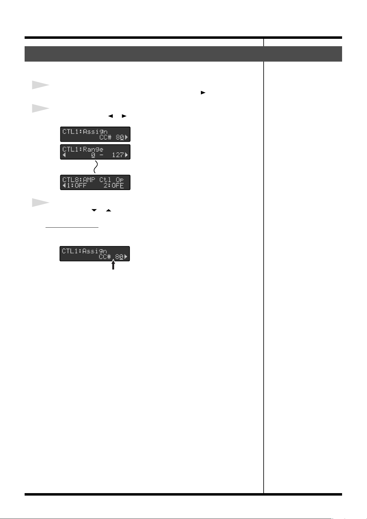
19 Standard Mode You can freely change the settings for each pedal. 1 In the Standard Mode’s top screen, press PARAMETER [ ]. 2 Press PARAMETER [ ] [ ] to display the pedal setting screens. 3 Press VALUE [ ] [ ] to change the value. MIDI Messages This selects the MIDI messages to be transmitted. fig.05-009 • OFF These do not output MIDI message[…]
-
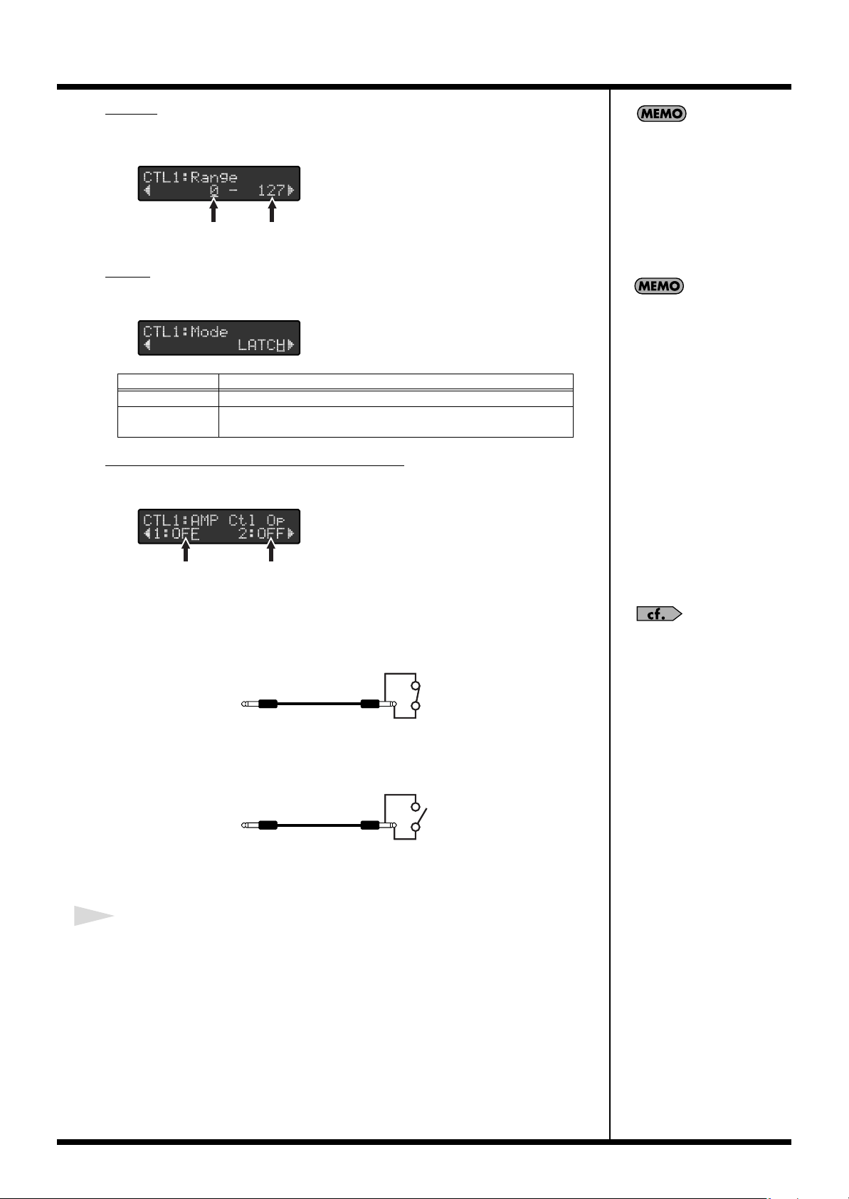
Страница 20
20 Standard Mode Range This sets the range for values that are transmitted. fig.05-009 Mode This sets the switch mode. fig.05-009 AMP Ctl Op (Amp Control Operation) This selects whether or not the AMP CONTROL jack is to be controlled. fig.05-009 When the AMP Ctl Op parameter is set to ON and the AMP Polarity parameter is set to Normal, control of A[…]
-
Страница 21
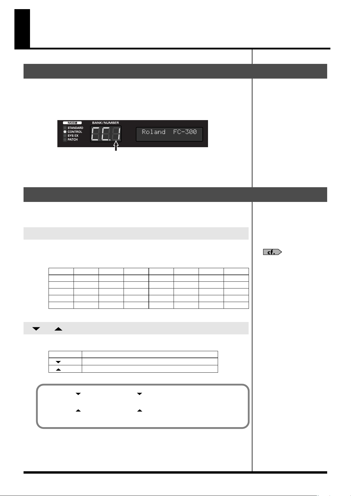
21 Control Change Mode This is the mode for sending Control Change messages. In this mode, all the pedals can be used to send Control Change messages. You should use this mode at times when you want to send a lot of Control Change messages. You can also store up to five sets, or configurations, of settings for all of the pedals within the FC-300’[…]
-
Страница 22
22 Control Change Mode In keeping with the movement of the expression pedal, Control Change messages with the controller numbers set for each pedal are transmitted consecutively. Each pedal is set at the factory as shown below. Control Change messages with the controller numbers set for each pedal are transmitted. Each pedal is set at the factory a[…]
-
Страница 23
23 Control Change Mode You can connect separately available footswitches and expression pedals and use the external pedals just like the FC-300’s pedals to transmit Control Change messages, Realtime messages, and other such data. When a BOSS FS-5U, FS-6 Footswitch is Connected, Assigned to CTL Pedal: These function in the same way as the FC-300?[…]
-
Страница 24
24 Control Change Mode You can freely change the settings for each pedal. 1 In the Control Change Mode’s top screen, press PARAMETER [ ]. 2 Pressing PARAMETER [ ] [ ] to show the pedal setting screens. 3 Press VALUE [ ] [ ] to change the value. MIDI Messages This selects the MIDI messages to be transmitted. fig.05-009 • OFF These do not output […]
-
Страница 25
25 Control Change Mode Range This sets the range for values that are transmitted. fig.05-009 Mode This sets the switch mode. fig.05-009 AMP Ctl Op (Amp Control Operation) This selects whether or not the AMP CONTROL jack is to be controlled. fig.05-009 When the AMP Ctl Op parameter is set to ON and the AMP Polarity parameter is set to Normal, contro[…]
-
Страница 26
26 Control Change Mode The FC-300 can store up to five different configurations of settings made for all of the pedals ( “Change the Pedal Settings” (p. 24)) in Control Change mode. These configurations are called pedal settings, and you can switch them as needed. 1 After completing the pedal settings (p. 24), press [WRITE] in the top screen of[…]
-
Страница 27
27 Control Change Mode 1 Press [WRITE] in the top screen of the Control Change Mode. 2 Pressing PARAMETER [ ] [ ] to show the “Delete” screen. 3 Select the number (1–5) for the pedal settings you want to delete with VALUE [] [ ] . 4 Press [WRITE]. “Sure?” appears in the display. 5 If you want to delete the setting, press [WRITE]; if you w[…]
-
Страница 28
28 System Exclusive Mode This mode is for transmitting and receiving System Exclusive messages. Pressing the FC-300’s pedals and pedals connected to the EXP PEDAL/CTL jacks transmits the pedal status via System Exclusive messages. In addition, display content and pedal indicators can be switched with System Exclusive messages received by the FC-3[…]
-
Страница 29
29 Patch Mode This mode is used for storing combinations of multiple MIDI messages that you can combine freely and transmitting these messages together in groups. This mode allows you to control the settings for multiple devices, all just with the FC-300. A “patch” is a group of multiple MIDI messages (MIDI stream) and other settings that are c[…]
-
Страница 30
30 Patch Mode You can transmit Control Change messages through operation of the expression pedals, control pedals, and other controllers. In keeping with the movement of the expression pedal, Control Change messages with the controller numbers set for each pedal are transmitted consecutively. Each pedal is set at the factory as shown below. All Ass[…]
-
Страница 31
31 Patch Mode You can connect separately available footswitches and expression pedals and use the external pedals just like the FC-300’s pedals to transmit Control Change messages, Realtime messages, and other such data. When a BOSS FS-5U, FS-6 Footswitch is Connected, Assigned to CTL Pedal: These function in the same way as the FC-300’s built-[…]
-
Страница 32
32 Patch Mode When a patch is selected with the [ ] and [ ] pedals and number pedals, the MIDI messages saved to the patch are transmitted. 1 Press the [ ] pedal, and the numbers decrease by five; press the [ ] pedal, and the numbers increase by five. The BANK/NUMBER display and Number pedal indicators flash. 2 The numbers are selected by pressing […]
-
Страница 33
33 Patch Mode In the Patch Mode’s top screen, when press PARAMETER [ ], the various pedal setting screens appear in the display. Press PARAMETER [ ] [ ] to select the parameter you want to change. The patch can set the following parameters. • Patch’s ON Stream • Patch’s OFF Stream • The Transmit timing of the patch’s Off Stream • ON[…]
-
Страница 34
34 Patch Mode 1 In the Patch Mode’s top screen, press PARAMETER [ ]. 2 Use the PARAMETER [ ] and [ ] buttons to select the MIDI stream you want to edit, then press [WRITE]. 3 “Edit MIDI” appears in the screen; press [WRITE]. The screen for selecting the MIDI stream editing function appears. The following display appears when the message is no[…]
-
Страница 35
35 Patch Mode When Setting Channel Messages and Realtime Messages 1 Press PARAMETER [ ] [ ] to move the cursor to the MIDI message. 2 Press VALUE [ ] [ ] to select the MIDI message to be edited. 3 Press PARAMETER [ ] [ ] to move the cursor to the parameter you want to change. 4 Press VALUE [ ] [ ] to change the value. If there is any other message […]
-
Страница 36
36 Patch Mode When Setting System Exclusive Messages 1 Press PARAMETER [ ] [ ] to move the cursor to the MIDI message. 2 Press VALUE [ ] [ ] to select the “SYSEX.” 3 Press [WRITE] to display the advanced editing screen. 4 Press PARAMETER [ ] [ ] to move the cursor to the data you want to change. 5 Press VALUE [ ] [ ] to change the value. 6 If y[…]
-
Страница 37
37 Patch Mode When Setting System Exclusive Messages Using the Template When assigning the following System Exclusive messages, use the template. 1 Press PARAMETER [ ] [ ] to move the cursor to the MIDI message. 2 Press VALUE [ ] [ ] to select the “SYSEX.” 3 Press PARAMETER [ ] to move the cursor to the “Template.” 4 Press [WRITE] to displa[…]
-
Страница 38
38 Patch Mode Copying and Moving MIDI Messages Within a Stream You can copy MIDI messages saved within a MIDI stream. Use this function when you want to program a number of similar messages in a stream. Messages in MIDI streams are output in the same order they are programmed. To change the sequence of the messages in a stream, use the Move functio[…]
-
Страница 39
39 Patch Mode You can copy an edited stream to a different patch or different stream. 1 In the Patch Mode’s top screen, press PARAMETER [ ]. 2 Press PARAMETER [ ] [ ] to select the stream to be used as the copy source, then press [WRITE]. 3 Press PARAMETER [ ] [ ] to select “Copy MIDI,” then press [WRITE]. 4 Press VALUE [ ] [ ] to select the […]
-
Страница 40
40 Patch Mode You can delete content in streams. 1 In the Patch Mode’s top screen, press PARAMETER [ ]. 2 Press PARAMETER [ ] [ ] to select the stream from which you want to delete data, then press [WRITE]. 3 Press PARAMETER [ ] [ ] to select “Delete MIDI,” then press [WRITE]. 4 “Sure?” appears in the display; press [WRITE] once more. 5 A[…]
-
Страница 41
41 Patch Mode You can set the status of the AMP CONTROL jacks when patches are selected. 1 In the Patch Mode’s top screen, press PARAMETER [ ]. 2 Press PARAMETER [ ] [ ] to select “AMP Ctl.” 3 Press PARAMETER [ ] [ ] to select “1” or “2” of the AMP Ctl. 4 Press VALUE [ ] [ ] to change the value. Control of AMP CONTROL when the AMP Pol[…]
-
Страница 42
42 Patch Mode You can freely change the settings for each pedal. 1 In the Patch Mode’s top screen, press PARAMETER [ ]. 2 Press PARAMETER [ ] [ ] to select the each pedal settings screen. The pedals being set appear at the left and upper of the screen. You can set the following parameters: • ON Stream • OFF Stream • Control Change Message ([…]
-
Страница 43
43 Patch Mode MMC REC EXIT / MMC REC PAUSE / MMC PAUSE This transmits MIDI Realtime messages and MMC messages. When assigned to an expression pedal, messages are output once the pedal is pressed downward past the halfway point; when assigned to a control pedal or other switch, the messages are output when the switch is on. • P.BEND/CH.PRS These t[…]
-
Страница 44
44 Patch Mode 4 When you have finished with the editing, press [EXIT]. The top screen appears. 5 After making the changes, follow the instructions in “Storing (Saving) Patches” (p. 44) to save the setting to a patch. 1 In the Patch mode’s top screen, press PARAMETER [ ]. 2 Press PARAMETER [ ] [ ] to select “Patch Name.” 3 Press PARAMETER […]
-
Страница 45
45 Patch Mode You can delete entire patches. 1 Select the patch you want to delete in the Patch mode’s top screen, then press [WRITE]. 2 Press PARAMETER [ ] to select “Delete.” 3 Press [WRITE]. 4 “Sure?” appears in the display; press [WRITE] once more. The selected patch is deleted, and the FC-300 returns to the top screen. Deleting Patch[…]
-
Страница 46
46 Other Features Set the system parameters with the following procedure. 1 Press [UTILITY]. The [UTILITY] indicator lights, and the Utility screen appears in the display. 2 Press PARAMETER [ ] [ ] to call up the parameter you want to set. Parameters that can be set and their screens are described in the next section. 3 Press VALUE [ ] [ ] to set t[…]
-
Страница 47
47 Other Features You can change the method used for transmitting program changes to match the device connected to the FC-300. 1 Press PARAMETER [ ] [ ] to select “SYS:PC Mode.” 2 Press VALUE [ ] [ ] to make the setting. When PC Mode parameter sets to “EFFECTS” and SYS:Bank Display parameter sets to “LINEAR,” the FC-300’s BANK/NUMBER […]
-
Страница 48
48 Other Features 1 Press PARAMETER [ ] [ ] to select “SYS:Bnk Chg Mode.” 2 Press the VALUE [ ] [ ] to program the settings. Here are some examples of operation in Standard Mode. 3 When you’ve finished making the settings, press [UTILITY] or [EXIT]. You can set an upper limit on the banks that can be switched, thus limiting the range of banks[…]
-
Страница 49
49 Other Features You can set the size of the step made when the [ ] [ ] pedals are pressed. 1 Press PARAMETER [ ] [ ] to select “SYS:Bank Step.” 2 Press VALUE [ ] [ ] to make the setting. 3 When you’ve finished making the settings, press [UTILITY] or [EXIT]. You can select the way numbers are indicated in Standard Mode to match that of the c[…]
-
Страница 50
50 Other Features Change this parameter if the indicator on an amp connected to an AMP CONTROL jack (1 or 2) does not correspond to the ON indicator (indicator lit) on the FC-300. 1 Press PARAMETER [ ] [ ] to select “SYS:AMP 1 Pol.” or “SYS:AMP 2 Pol.” 2 Press VALUE [ ] [ ] to make the setting. 3 When you’ve finished making the settings, […]
-
Страница 51
51 Other Features This sets the modes that can be selected when the mode is switched with a pedal. This setting allows you to toggle only between the modes you need when using the pedal. 1 Press PARAMETER [ ] [ ] to select “SYS:MODE Pdl Seq.” 2 Press PARAMETER [ ] [ ] to select the mode you want to set, then press VALUE [ ] [ ] to make the sett[…]
-
Страница 52
52 Other Features This sets the Transmit Channel of the MIDI messages. 1 Press PARAMETER [ ] [ ] to select “MIDI:Tx Channel.” 2 Press VALUE [ ] [ ] to set the transmit channel. 3 When you’ve finished making the settings, press [UTILITY] or [EXIT]. This sets the Device ID used for transmitting and receiving system exclusive messages. 1 Press P[…]
-
Страница 53
53 Other Features You can change the values of the Bank Select messages output in Standard Mode to match the connected device. Values from the [ ] [ ] pedals are added to the base values set here and then output. For details, refer to “Setting the Method Used for Transmitting Program Change messages in Standard Mode (PC Mode)” (p. 47). 1 Press […]
-
Страница 54
54 Other Features 2 Press VALUE [ ] [ ] to make the setting. 3 Press [WRITE]. The “Now Sending…” message appears in the display when the FC-300 sends the data. The top screen appears in the display when the FC-300 finishes sending the data. If either ALL, CONTROL, or PATCH is selected in Step 2, the message “Erase Tmp Data Sure?” is displ[…]
-
Страница 55
55 Appendices You can restore all of the FC-300’s settings to their original factory settings. This is referred to as “Factory Reset.” Use the following procedure when carrying out Factory Reset. 1 Switch off the power. 2 Hold down VALUE [ ] [ ] and switch on the power. The message “Factory Reset Are you sure?” appears in the display. 3 P[…]
-
Страница 56
56 Appendices Although the FC-300’s EXP pedals are adjusted for optimal performance when shipped from the factory, extended use over time and under certain usage conditions may result in the pedals going out of adjustment. If you find the pedals exhibiting problems, such as “a failure to completely shut off the volume when used as volume pedals[…]
-
Страница 57
57 Appendices [Cause] The batteries are depleted (6 x AA size). [Solution] Replace the batteries as soon as possible. (p. 11) [Cause 1] The internal memory became full at the time the patch was saved. [Solution 1] Delete any unnecessary patches. (p. 45) [Cause 2] The area of memory for the FC-300’s internal operations became full while the patch […]
-
Страница 58
58 Appendices If other operational problems occur, first check by using the following solutions: If this does not resolve the problem, then contact your dealer or a nearby Roland service station. The power doesn’t come on • Is the specified AC adaptor (PSA series; sold separately) properly connected? Check connections again. Never use any AC ad[…]
-
Страница 59
59 MIDI FOOT CONTROLLER Model FC-300 Apr. 1, 2007 Version 1.00 MIDI Implementation Roland’s MIDI implementation uses the following data format for all Exclusive messages (type IV): MIDI status: F0H, F7H An Exclusive message must be flanked by a pair of status codes, starting with a Manufacturer ID immediately after F0H (MIDI version 1.0). Manufac[…]
-
Страница 60
60 MIDI Implementation Handshake-transfer procedure (This device does not use this procedure) This procedure initiates a predetermined transfer sequence (handshaking) across the interface before data transfer takes place. Handshaking ensures that reliability and transfer speed are high enough to handle a large amount of data. fig.Connection-Diagram[…]
-
Страница 61
61 MIDI Implementation address, size, and that checksum are summed. Data set 1: DT1 (12H) This message corresponds to the actual data transfer process. Because every byte in the data is assigned a unique address, a DT1 message can convey the starting address of one or more bits of data as well as a series of data formatted in an address-dependent o[…]
-
Страница 62
62 MIDI Implementation System Realtime Message Active Sensing When FC-300 receives Active Sensing, it measures time intervals between incoming messages. If the subsequent message will not come within 400 msec after the previous one, FC-300 turns off Active Sensing for a period and stops measuring message intervals. System Exclusive Message System E[…]
-
Страница 63
63 MIDI Implementation Program Change * Specifically when Standard Mode and Patch Mode are selected. Channel Pressure * Does not transmit while in System Exclusive Mode. Pitch Bend Change * Does not transmit while in System Exclusive Mode. System Realtime Message Start * Does not transmit while in System Exclusive Mode. Continue * Does not transmit[…]
-
Страница 64
64 MIDI Implementation Using Roland’s one-way System Exclusive message you can transfer data between FC-300 and another device. You can use the following Model ID for the FC-300. • 00H 00H 1EH (FC-300) You can use System Exclusive messages to transmit and receive the FC-300’s internal parameters in the form of bulk data. • 00H 00H 20H (Foot[…]
-
Страница 65
65 MIDI Implementation Pedal Status (Individual area) • Outputs when pedal is operated while in the System Exclusive Mode. • Also outputs Data Set (DT1) when Data Request (RQ1) is received. • Data Set (DT1) is ignored. LED Status (Individual area) • Receives Data Set (DT1) in all mode, changes the LED status of each pedal only in the System[…]
-
Страница 66
66 MIDI Implementation Controller Status (Individual area) • Receives Data Set (DT1) in all mode. • Changes status of AMP CONTROL jack when Data Set (DT1) is received. • Outputs when Data Request (RQ1) is received. Message Display Status (Individual area) • Receives Data Set (DT1) in all mode. • Outputs when Data Request (RQ1) is received[…]
-
Страница 67
67 MIDI Implementation Function… Basic Channel Mode Note Number Velocity After Touch Pitch Bend Control Change Program Change System Exclusive Common System Realtime AUX Messages Notes Transmitted Recognized Remarks Default Changed Default Messages Altered True Voice Note ON Note OFF Key’s Ch’s 0, 32 1 – 31 33 – 95 True # Song Posit[…]
-
Страница 68
68 Specifications * In the interest of product development, the specifications and/or appearance of this unit are subject to change without prior notice. FC-300 : MIDI FOOT CONTROLLER Connectors MIDI connectors (IN, OUT) MODE jack EXP PEDAL/CTL jack (3/3,4 4/5,6 5/7,8) AMP CONTROL jack (1, 2) RRC2 OUT connector DC IN jack Controls Number pedals 1/6[…]
-
Страница 69
69 Index Numerics 1/6 – 5/10 pedals …………………………………………………… 9 1/6–5/10 ………………………………………………………………. 21 A AMP 1 Pol. ……………………………………………………………. 50 AMP 2 Pol. ………………………………………………………[…]
-
Страница 70
70 Index System Exclusive Messages ………………………………….. 59 System Exclusive Mode ………………………………………… 14 System Parameters ……………………………………………….. 46 T Threshold ……………………………………………………………… 56 Troubleshooting …………..[…]
-
Страница 71
IMPORTANT: THE WIRES IN THIS MAINS LEAD ARE COLOURED IN ACCORDANCE WITH THE FOLLOWING CODE. BLUE: BROWN: As the colours of the wires in the mains lead of this apparatus may not correspond with the coloured markings identifying the terminals in your plug, proceed as follows: The wire which is coloured BLUE must be connected to the terminal which is […]
-
Страница 72
04564278 07-04-1N As of November 1, 2006 (ROLAND) Information When you need repair service, call your nearest Roland Service Center or authorized Roland distributor in your country as shown below. EGYPT Al Fanny Trading Office 9, EBN Hagar A1 Askalany Street, ARD E1 Golf, Heliopolis, Cairo 11341, EGYPT TEL: 20-2-417-1828 REUNION Maison FO — YAM Mar[…]
- Главная
-
Roland
-
Педали музыкальных эффектов
-
FC-300
На этой странице вы найдёте полный список документов на Педали музыкальных эффектов Roland FC-300.
Выберите необходимый PDF файл.
-
Педали музыкальных эффектов
Roland FC-300 Инструкция по эксплуатацииТип файла
PDFРазмер
3.91 MbКол-во страниц
72Просмотров
4413Download / Read online
- 1
Другие Roland Педали музыкальных эффектов
-
Roland VG-99 Инструкция по эксплуатации
PDF файлов
1Просмотров
8926 -
Roland Bass Pedals PK-9 Инструкция по эксплуатации
PDF файлов
1Просмотров
6658 -
Roland PC-300 Инструкция по эксплуатации
PDF файлов
1Просмотров
6098 -
Roland FC-300 Инструкция по эксплуатации
PDF файлов
1Просмотров
5546 -
Roland FC-200 Инструкция по эксплуатации
PDF файлов
1Просмотров
3568 -
Roland Guitar Multiple Effects ME-70 Инструкция по эксплуатации
PDF файлов
1Просмотров
2497
Другие устройства Roland
-
Музыкальные инструменты
Roland SC-88 Pro Инструкция по эксплуатацииPDF файлов
1Просмотров
23875 -
Принтеры
Roland SC-545EX Инструкция по эксплуатацииPDF файлов
1Просмотров
20737 -
Принтеры
Roland SJ-745EX Инструкция по эксплуатацииPDF файлов
1Просмотров
17860 -
Принтеры
Roland SJ-645EX Инструкция по эксплуатацииPDF файлов
1Просмотров
17289 -
Барабаны
Roland TD-10 Инструкция по эксплуатацииPDF файлов
1Просмотров
15980 -
Электронная клавиатура
Roland DP-990 Инструкция по эксплуатацииPDF файлов
1Просмотров
14997
Ранее вы смотрели
Производители
BBE
Cadco
Ditch Witch
Fitbit
Mantis
MTD
Superchips
System Sensor
Vicks
Wherify Wireless
Типы устройств
Радио-антенны
Компактные экскаваторы
Штамп-часы
Автомобильные аксессуары
Комплекты угловых и накидных ключей
Brad нейлеры и аксессуары
Трансиверы
Медицинские устройства с дисплеем
Пищевая добавка Nutri Ninja
Газовые котлы
Устройства
Continental Electric CE11125
JVC AV-32MF47
Lexmark 4098-001
Motorola cellular phone
Philips QG3040/10
Pioneer DV-F07
QSC BASIS 722az
Toshiba TEC MA-186
freeuserguide.ru
About Us
Contacts
Disclamers
Privacy Policy
Эта страница полезна для вас? Поделитесь ссылкой:
Owner’s Manual
201a
Before using this unit, carefully read the sections entitled: “USING THE UNIT SAFELY” (p. 2)
and “IMPORTANT NOTES” (p. 4). These sections provide important information concerning
the proper operation of the unit. Additionally, in order to feel assured that you have gained a
good grasp of every feature provided by your new unit, Owner’s Manual should be read in its
entirety. The manual should be saved and kept on hand as a convenient reference.
202
Copyright © 2007 ROLAND CORPORATION
All rights reserved. No part of this publication may be reproduced in any form without the
written permission of ROLAND CORPORATION.
USING THE UNIT SAFELY
Used for instructions intended to alert
the user to the risk of death or severe
injury should the unit be used
improperly.
Used for instructions intended to alert
the user to the risk of injury or material
damage should the unit be used
improperly.
* Material damage refers to damage or
other adverse effects caused with
respect to the home and all its
furnishings, as well to domestic
animals or pets.
001
• Before using this unit, make sure
to read the instructions below,
and the Owner’s Manual.
……………………………………………………………..
002c
• Do not open (or modify in any
way) the unit or its AC adaptor.
……………………………………………………………..
003
• Do not attempt to repair the unit,
or replace parts within it (except
when this manual provides
specific instructions directing
you to do so). Refer all servicing
to your retailer, the nearest
Roland Service Center, or an
authorized Roland distributor, as
listed on the “Information” page.
……………………………………………………………..
004
• Never use or store the unit in
places that are:
• Subject to temperature
extremes (e.g., direct sunlight
in an enclosed vehicle, near a
heating duct, on top of heatgenerating equipment); or are
• Damp (e.g., baths, washrooms, on wet
floors); or are
• Humid; or are
• Exposed to rain; or are
• Dusty; or are
• Subject to high levels of vibration.
……………………………………………………………..
007
• Make sure you always have the
unit placed so it is level and sure
to remain stable. Never place it
on stands that could wobble, or
on inclined surfaces.
……………………………………………………………..
The symbol alerts the user to important instructions
or warnings.The specific meaning of the symbol is
determined by the design contained within the
triangle. In the case of the symbol at left, it is used for
general cautions, warnings, or alerts to danger.
The symbol alerts the user to items that must never
be carried out (are forbidden). The specific thing that
must not be done is indicated by the design contained
within the circle. In the case of the symbol at left, it
means that the unit must never be disassembled.
The ● symbol alerts the user to things that must be
carried out. The specific thing that must be done is
indicated by the design contained within the circle. In
the case of the symbol at left, it means that the powercord plug must be unplugged from the outlet.
008b
• Use only the specified AC
adaptor (PSA series), and make
sure the line voltage at the installation matches the input voltage
specified on the AC adaptor’s
body. Other AC adaptors may
use a different polarity, or be
designed for a different voltage,
so their use could result in
damage, malfunction, or electric
shock.
…………………………………………………………….
009
• Do not excessively twist or bend
the power cord, nor place heavy
objects on it. Doing so can
damage the cord, producing
severed elements and short
circuits. Damaged cords are fire
and shock hazards!
…………………………………………………………….
011
• Do not allow any objects (e.g.,
flammable material, coins, pins);
or liquids of any kind (water, soft
drinks, etc.) to penetrate the unit.
…………………………………………………………….
013
• In households with small
children, an adult should
provide supervision until the
child is capable of following all
the rules essential for the safe
operation of the unit.
…………………………………………………………….
014
• Protect the unit from strong
impact.
(Do not drop it!)
…………………………………………………………….
016
• Before using the unit in a foreign
country, consult with your
retailer, the nearest Roland
Service Center, or an authorized
Roland distributor, as listed on
the “Information” page.
…………………………………………………………….
012c
• Immediately turn the power off,
remove the AC adaptor from the
outlet, and request servicing by
your retailer, the nearest Roland
Service Center, or an authorized
Roland distributor, as listed on
the “Information” page when:
• The AC adaptor or the power-
supply cord has been
damaged; or
• If smoke or unusual odor occurs
• Objects have fallen into, or liquid has
been spilled onto the unit; or
• The unit has been exposed to rain (or
otherwise has become wet); or
• The unit does not appear to operate
normally or exhibits a marked change
in performance.
……………………………………………………………..
015
• Do not force the unit’s powersupply cord to share an outlet
with an unreasonable number of
other devices. Be especially
careful when using extension
cords—the total power used by
all devices you have connected to
the extension cord’s outlet must
never exceed the power rating
(watts/amperes) for the
extension cord. Excessive loads
can cause the insulation on the
cord to heat up and eventually
melt through.
……………………………………………………………..
019
• Batteries must never be
recharged, heated, taken apart, or
thrown into fire or water.
……………………………………………………………..
2
101b
• The unit and the AC adaptor
should be located so their
location or position does not
interfere with their proper ventilation.
……………………………………………………………..
102d
• Always grasp only the output
plug or the body of the AC
adaptor when plugging into, or
unplugging from, this unit or an
outlet.
……………………………………………………………..
103b
• At regular intervals, you should
unplug the AC adaptor and clean
it by using a dry cloth to wipe all
dust and other accumulations
away from its prongs. Also,
disconnect the power plug from
the power outlet whenever the
unit is to remain unused for an
extended period of time. Any
accumulation of dust between
the power plug and the power
outlet can result in poor
insulation and lead to fire.
……………………………………………………………..
104
• Try to prevent cords and cables
from becoming entangled. Also,
all cords and cables should be
placed so they are out of the
reach of children.
……………………………………………………………..
106
• Never climb on top of, nor place
heavy objects on the unit.
……………………………………………………………..
107d
• Never handle the AC adaptor
body, or its output plugs, with
wet hands when plugging into,
or unplugging from, an outlet or
this unit.
…………………………………………………………….
108b
• Before moving the unit,
disconnect the AC adaptor and
all cords coming from external
devices.
…………………………………………………………….
109b
• Before cleaning the unit, turn off
the power and unplug the AC
adaptor from the outlet (p. 13).
…………………………………………………………….
110b
• Whenever you suspect the possibility of lightning in your area,
disconnect the AC adaptor from
the outlet.
…………………………………………………………….
112
• Used batteries must be disposed
of in compliance with whatever
regulations for their safe disposal
that may be observed in the region in
which you live.
…………………………………………………………….
111: Selection
• If used improperly, batteries
may explode or leak and cause
damage or injury. In the interest
of safety, please read and
observe the following precautions (p. 11).
1
• Carefully follow the instal-
lation instructions for
batteries, and make sure you
observe the correct polarity.
2
• Avoid using new batteries
together with used ones. In addition,
avoid mixing different types of
batteries.
3
• Remove the batteries whenever the
unit is to remain unused for an
extended period of time.
5
• If a battery has leaked, use a soft piece
of cloth or paper towel to wipe all
remnants of the discharge from the
battery compartment. Then install new
batteries. To avoid inflammation of the
skin, make sure that none of the
battery discharge gets onto your hands
or skin. Exercise the utmost caution so
that none of the discharge gets near
your eyes. Immediately rinse the
affected area with running water if any
of the discharge has entered the eyes.
6
• Never keep batteries together with
metallic objects such as ballpoint pens,
necklaces, hairpins, etc.
……………………………………………………………..
UK
DE
FR
IT
ES
PT
NL
DK
For EU Countries
SE
FI
HU
PL
CZ
SK
EE
LT
LV
SI
NO
GR
3

IMPORTANT NOTES
291a
In addition to the items listed under “USING THE UNIT
SAFELY” on page 2, please read and observe the following:
Power Supply: Use of
Batteries
301
• Do not connect this unit to same electrical outlet that is
being used by an electrical appliance that is controlled by
an inverter (such as a refrigerator, washing machine,
microwave oven, or air conditioner), or that contains a
motor. Depending on the way in which the electrical
appliance is used, power supply noise may cause this unit
to malfunction or may produce audible noise. If it is not
practical to use a separate electrical outlet, connect a
power supply noise filter between this unit and the
electrical outlet.
302
• The AC adaptor will begin to generate heat after long
hours of consecutive use. This is normal, and is not a
cause for concern.
303a
• The use of an AC adaptor is recommended as the unit’s
power consumption is relatively high.
304a
• When installing or replacing batteries, always turn off the
power on this unit and disconnect any other devices you
may have connected. This way, you can prevent
malfunction and/or damage to speakers or other devices.
306b
• Batteries are supplied with the unit. The life of these
batteries may be limited, however, since their primary
purpose was to enable testing.
307
• Before connecting this unit to other devices, turn off the
power to all units. This will help prevent malfunctions
and/or damage to speakers or other devices.
Placement
352a
• This device may interfere with radio and television
reception. Do not use this device in the vicinity of such
receivers.
354a
• Do not expose the unit to direct sunlight, place it near
devices that radiate heat, leave it inside an enclosed
vehicle, or otherwise subject it to temperature extremes.
Excessive heat can deform or discolor the unit.
355b
• When moved from one location to another where the
temperature and/or humidity is very different, water
droplets (condensation) may form inside the unit. Damage
or malfunction may result if you attempt to use the unit in
this condition. Therefore, before using the unit, you must
allow it to stand for several hours, until the condensation
has completely evaporated.
360
• Depending on the material and temperature of the surface
on which you place the unit, its rubber feet may discolor
or mar the surface.
Maintenance
401a
• For everyday cleaning wipe the unit with a soft, dry cloth
or one that has been slightly dampened with water. To
remove stubborn dirt, use a cloth impregnated with a
mild, non-abrasive detergent. Afterwards, be sure to wipe
the unit thoroughly with a soft, dry cloth.
402
• Never use benzine, thinners, alcohol or solvents of any
kind, to avoid the possibility of discoloration and/or
deformation.
Repairs and Data
452
• Please be aware that all data contained in the unit’s
memory may be lost when the unit is sent for repairs.
Important data should always be backed up in another
MIDI device (e.g., a sequencer), or written down on paper
(when possible). During repairs, due care is taken to avoid
the loss of data. However, in certain cases (such as when
circuitry related to memory itself is out of order), we
regret that it may not be possible to restore the data, and
Roland assumes no liability concerning such loss of data.
Additional Precautions
551
• Please be aware that the contents of memory can be
irretrievably lost as a result of a malfunction, or the
improper operation of the unit. To protect yourself against
the risk of loosing important data, we recommend that
you periodically save a backup copy of important data
you have stored in the unit’s memory in another MIDI
device (e.g., a sequencer).
552
• Unfortunately, it may be impossible to restore the contents
of data that was stored in another MIDI device (e.g., a
sequencer) once it has been lost. Roland Corporation
assumes no liability concerning such loss of data.
553
• Use a reasonable amount of care when using the unit’s
buttons, sliders, or other controls; and when using its jacks
and connectors. Rough handling can lead to malfunctions.
554
• Never strike or apply strong pressure to the display.
556
• When connecting / disconnecting all cables, grasp the
connector itself—never pull on the cable. This way you
will avoid causing shorts, or damage to the cable’s
internal elements.
558b
• To avoid disturbing your neighbors, try to keep the unit’s
volume at reasonable levels (especially when it is late at
night).
558c
• Since sound vibrations can be transmitted through floors
and walls to a greater degree than expected, take care not
to allow such sound to become a nuisance to neighbors,
especially at night and when using headphones.
559a
• When you need to transport the unit, package it in the box
(including padding) that it came in, if possible. Otherwise,
you will need to use equivalent packaging materials.
561
• Use only the specified expression pedal (Roland EV-5,
BOSS FV-500L or FV-500H; sold separately). By
connecting any other expression pedals, you risk causing
malfunction and/or damage to the unit.
4

Table of Contents
Introduction …………………………………………………………………………………7
Main Features……………………………………………………………………………………………………………………………. 7
Panel Descriptions…………………………………………………………………………………………………………………….. 7
Display……………………………………………………………………………………………………………………………. 7
Top Panel (Buttons) ………………………………………………………………………………………………………… 8
Top Panel (Pedals) ………………………………………………………………………………………………………….. 9
Rear Panel……………………………………………………………………………………………………………………… 10
Making the Connections………………………………………………………………………………………………………….. 11
Connections To Make When Using the FC-300 as a MIDI Foot Controller…………………….. 11
Connections To Make When Using the FC-300 as a Dedicated Foot Controller
for an RRC2 IN Device (e.g., the VG-99)………………………………………………………………………… 12
Turning the Power On and Off ……………………………………………………………………………………………….. 13
When Using the FC-300 as a MIDI Foot Controller ……………………………………………………….. 13
When Using the FC-300 as a Dedicated Foot Controller for an RRC2 IN Device
(e.g., the VG-99)…………………………………………………………………………………………………………….. 13
About the MODES…………………………………………………………………………………………………………………… 14
Standard Mode (p. 16) …………………………………………………………………………………………………… 14
Control Change Mode (p. 21) ………………………………………………………………………………………… 14
System Exclusive Mode (p. 28)………………………………………………………………………………………. 14
Patch Mode (p. 29) ………………………………………………………………………………………………………… 14
Switching Modes …………………………………………………………………………………………………………………….. 15
About the Mode Indicators……………………………………………………………………………………………. 15
Standard Mode …………………………………………………………………………..16
Transmitting Program Change Messages………………………………………………………………………………… 16
Setting How Tones are Switched…………………………………………………………………………………… 16
Transmitting Control Change Messages………………………………………………………………………………….. 17
Using the Expression Pedals …………………………………………………………………………………………. 17
Using the Control Pedal and Expression Pedal Switch………………………………………………….. 17
Using the External Control Pedals and Expression Pedals…………………………………………….. 18
Controller Numbers for Each Pedal ………………………………………………………………………………. 18
Change the Pedal Settings……………………………………………………………………………………………………….. 19
Control Change Mode…………………………………………………………………21
About the Control Change Mode…………………………………………………………………………………………….. 21
Transmitting Control Change Messages………………………………………………………………………………….. 21
Number Pedal (1/6–5/10) …………………………………………………………………………………………….. 21
[ ] [ ] Pedal ……………………………………………………………………………………………………………. 21
Using the Expression Pedals …………………………………………………………………………………………. 22
Using the Control Pedal and Expression Pedal Switch………………………………………………….. 22
Using Additional Footswitches and Expression Pedals…………………………………………………. 23
Controller Numbers of the Pedals …………………………………………………………………………………. 23
Change the Pedal Settings……………………………………………………………………………………………………….. 24
Storing Controller Numbers Assigned to the Pedals (Pedal Settings) ………………………………………26
Switching Control Numbers Assigned to the Pedals Simultaneously ……………………………………… 26
Deleting a Pedal Setting…………………………………………………………………………………………………………… 27
System Exclusive Mode ……………………………………………………………..28
Patch Mode………………………………………………………………………………..29
About the Patch Mode …………………………………………………………………………………………………………….. 29
About the Patch …………………………………………………………………………………………………………….. 29
Transmitting Control Change Messages………………………………………………………………………………….. 30
Using the Expression Pedals …………………………………………………………………………………………. 30
Using the Control Pedals and Expression Pedal Switches……………………………………………… 30
Using the External Control Pedals and Expression Pedals…………………………………………….. 31
The Controller Number of Each Pedal…………………………………………………………………………… 31
Transmitting Patch Data………………………………………………………………………………………………………….. 32
Creating Patches ……………………………………………………………………………………………………………………… 33
Editing MIDI Streams……………………………………………………………………………………………………. 34
5

How to Copy MIDI Streams…………………………………………………………………………………………..39
How to Delete MIDI Streams …………………………………………………………………………………………40
Setting the Timing for Transmission of OFF MIDI Streams …………………………………………… 40
Setting the Amp Control ……………………………………………………………………………………………….. 41
Change the Pedal Settings……………………………………………………………………………………………………….. 42
Set the Patch Name …………………………………………………………………………………………………………………. 44
Storing (Saving) Patches………………………………………………………………………………………………………….. 44
Deleting Patches ……………………………………………………………………………………………………………………… 45
Other Features …………………………………………………………………………..46
Setting the System Parameters …………………………………………………………………………………………………46
Adjusting the LCD Contrast………………………………………………………………………………………….. 46
Reducing Battery Consumption (Economy Mode)………………………………………………………… 46
Setting the Method Used for Transmitting Program Change messages
in Standard Mode (PC Mode) ………………………………………………………………………………………..47
Using the [ ] [ ] Pedals to Make the Settings …………………………………………………………. 48
Limiting the Range of Banks That Can Be Switched (Bank Extent) ……………………………….. 48
Setting the [ ] [ ] Pedal Step Size …………………………………………………………………………… 49
Setting How Numbers are Indicated……………………………………………………………………………… 49
Setting the Polarity of the AMP CONTROL Jacks ………………………………………………………….50
Determining the Role of an EXP PEDAL/CTL Jack ………………………………………………………. 50
Switching the Function of the MODE Pedal Jack…………………………………………………………… 51
Switching How the Pedal Indicators Light …………………………………………………………………….51
Setting the MIDI Transmit Channel ………………………………………………………………………………. 52
Setting the Device ID …………………………………………………………………………………………………….. 52
Setting the Bank Select Output………………………………………………………………………………………. 52
Setting the Bank Select Value ………………………………………………………………………………………… 53
Transmitting Data to an External MIDI Device (Bulk Dump) ……………………………………….. 53
Receiving Data from an External MIDI Device (Bulk Load) ………………………………………….. 54
Appendices………………………………………………………………………………..55
Restoring the Factory Settings (Factory Reset)…………………………………………………………………………. 55
Adjusting the Expression Pedal ………………………………………………………………………………………………. 56
Error Messages………………………………………………………………………………………………………………………… 57
Battery Low!………………………………………………………………………………………………………………….. 57
Memory Full! …………………………………………………………………………………………………………………57
MIDI Buffer Full!…………………………………………………………………………………………………………… 57
MIDI Offline!…………………………………………………………………………………………………………………. 57
RRC2 Buffer Full! …………………………………………………………………………………………………………..57
RRC2 Offline!………………………………………………………………………………………………………………… 57
Troubleshooting………………………………………………………………………………………………………………………. 58
MIDI Implementation…………………………………………………………………..59
Roland System Exclusive Messages…………………………………………………………………………………………. 59
1. Data Format for Exclusive Messages …………………………………………………………………………. 59
2. Address-mapped Data Transfer ………………………………………………………………………………… 59
3. One-way Transfer Procedure ……………………………………………………………………………………..60
1. Recognized Receive Data ……………………………………………………………………………………………………..62
2. Transmitted Data…………………………………………………………………………………………………………………. 62
Transmitted Messages…………………………………………………………………………………………………… 62
3. Exclusive Communications………………………………………………………………………………………………….. 64
4. Parameter Address Map (Model ID = 00H 00H 20H)…………………………………………………………… 64
Specifications…………………………………………………………………………….68
FC-300 : MIDI FOOT CONTROLLER ………………………………………………………………………………………68
Index………………………………………………………………………………………….69
6

Introduction
Main Features
• Features four modes (Standard Mode, Control Change Mode, System Exclusive
Mode, Patch Mode)
• Unit comes equipped with two expression pedals and two control pedals.
You can also expand control even further with up to three external expression
pedals or six external control pedals.
• Includes 16-character x 2-line LCD
• Equipped with RRC2 OUT connector; enables connection with RRC2 IN
compatible devices with a single cable
• Includes two separate amp control channels
• Features three-way power supply (AC Adaptor, Dry battery, RRC2)
Panel Descriptions
Display
1
MODE indicator
The current mode is indicated here. (p. 15)
2
BANK/NUMBER display
The currently selected bank and number are indicated here.
3
Liquid Crystal display (LCD)
A variety of information is shown in this display.
7
Introduction
• By continuing to hold down
VALUE for a number of
seconds, the value of the
setting can be increased/
decreased continuously.
• The value will increase
rapidly if you hold down
VALUE [ ], then press
and hold VALUE [ ].
• The value will decrease
rapidly if you hold down
VALUE [ ], then press
and hold [ ].
Top Panel (Buttons)
1
4
2
5
3
6
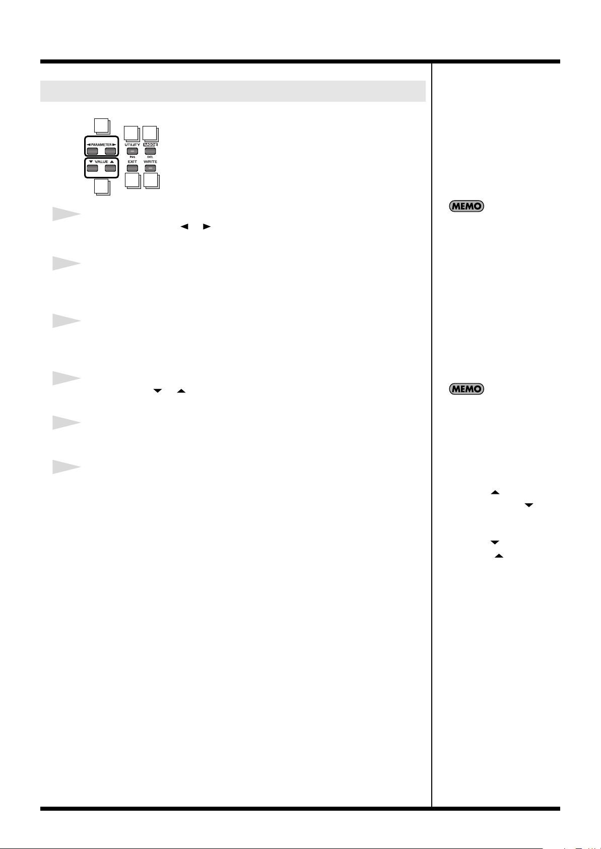
1
PARAMETER button [ ] [ ]
Press these to select parameters.
2
UTILITY button / INS (insert) button
Press this when changing system settings. In the Edit screen, this is used to insert
MIDI messages and blank spaces.
3
MODE button / DEL (delete) button
Press this to change the FC-300’s operating mode. In the Edit screen, this is used to
delete a MIDI message or a character at the cursor location.
4
VALUE button [ ] [ ]
Use this when changing the values of settings.
To jump to the main
parameters, hold down one of
these buttons while you press
the other. With items for which
there aren’t that many
parameters, the FC-300 jumps
to the last (or initial)
parameter.
5
EXIT button
Press this to undo an operation and return to the previous screen.
6
WRITE button
Press this to store settings and execute procedures.
8
Top Panel (Pedals)
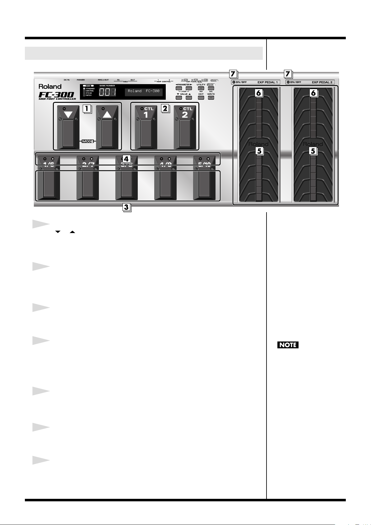
Introduction
1
[ ] [ ] (down / up) pedals
Use these pedals to switch banks and select numbers.
Additionally, you can switch modes by pressing the pedals simultaneously.
2
CTL (Control) pedals (1, 2)
You can assign the desired functions to these pedals, then use them for control over
those functions.
3
Number pedals (1/6 – 5/10)
These switch the patch numbers.
4
Number pedal indicators (1/6 – 5/10)
The indicator for the currently selected number lights.
A red indicator lights when a number from 1 through 5 is selected; a green indicator
lights when a number from 6 through 10 is selected.
5
EXP PEDAL (expression pedal) (1, 2)
These control the volume, wah, or other aspects of connected devices.
6
EXP PEDAL SW (expression pedal switch) (1, 2)
Firmly press down at the front of the pedal to switch the effect on and off.
When you operate the
expression pedal, please be
careful not to get your fingers
pinched between the movable
part and the panel. In
households with small
children, an adult should
provide supervision until the
child is capable of following all
the rules essential for the safe
operation of the unit.
7
EXP PEDAL SW indicators (expression pedal switch indicators) (1, 2)
Lights when the effect being controlled with the EXP PEDAL SW is on, and goes out
when the effect is turned off.
9
Introduction
Rear Panel
2
3
4
1
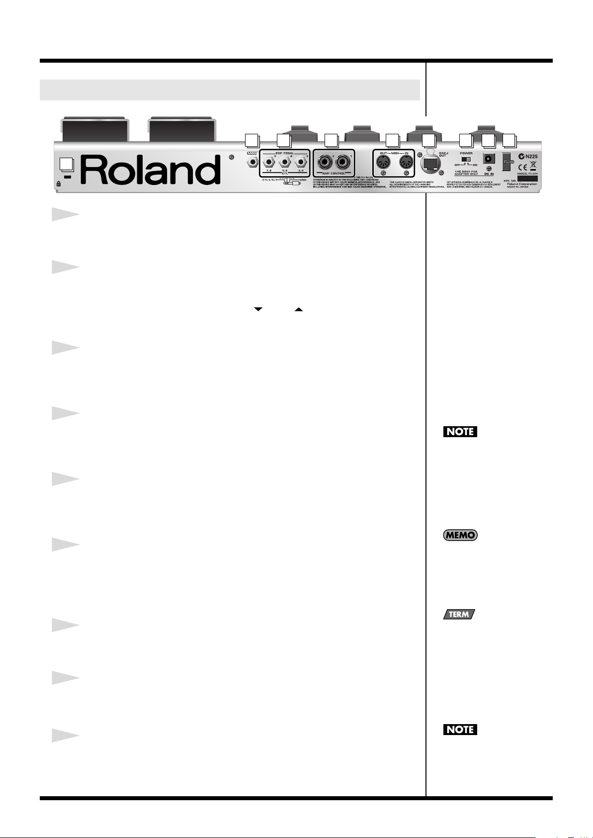
1
Security Slot
http://www.kensington.com/
2
MODE jack
Connect an optional footswitch (such as the BOSS FS-5U) here.
The function is the same as that when the [ ] and [ ] pedals are held down
simultaneously.
3
EXP PEDAL/CTL jack
Connect an optional expression pedal (such as the Roland EV-5, BOSS FV-500L/FV500H) or footswitch (such as the BOSS FS-5U/FS-6) here.
4
AMP CONTROL 1, 2 jack
When using the AMP CONTROL function, connect to the jack used for switching
guitar amp channels.
5
MIDI connectors (OUT, IN)
Connect an external MIDI device to these connectors to transmit and receive MIDI
messages.
5
6
Be sure to connect the RRC2
OUT connector to a device
with an RRC2 IN connector.
Use of the connection with
other devices may cause
generation of heat and damage
to the equipment.
8
7
9
10
6
RRC2 OUT connector
You can connect an external RRC2 IN device here to transmit and receive
performance data between the devices.
At the same time, the FC-300 can be powered by the external RRC2 IN device.
7
POWER switch
Turns the power on and off.
8
DC IN (AC Adaptor) jack
Connect the AC adaptor (PSA series; sold separately) here.
9
Cord Hook
Hook the AC adaptor cord here to prevent the adaptor plug from being
disconnected. Refer to
“Connecting an AC Adaptor”
(p. 12).
When running on power
supplied by an RRC2 IN
device, the power is switched
on regardless of the position of
the POWER switch.
RRC2 is a Roland standard
developed to enable two-way
communications between
RRC2 IN devices and RRC2
OUT devices, while supplying
power to the RRC2 OUT
device from the RRC2 IN
device, all with a single cable.
You must use only the PSA
series AC adaptor. Use of any
other adaptor may cause
overheating or malfunctions.
Making the Connections
When making connections to other equipment, be sure that all equipment is
switched off. If you try to make connections while the power is turned on, the
settings for the FC-300 may be changed.
Connections To Make When Using the FC-300 as a
MIDI Foot Controller
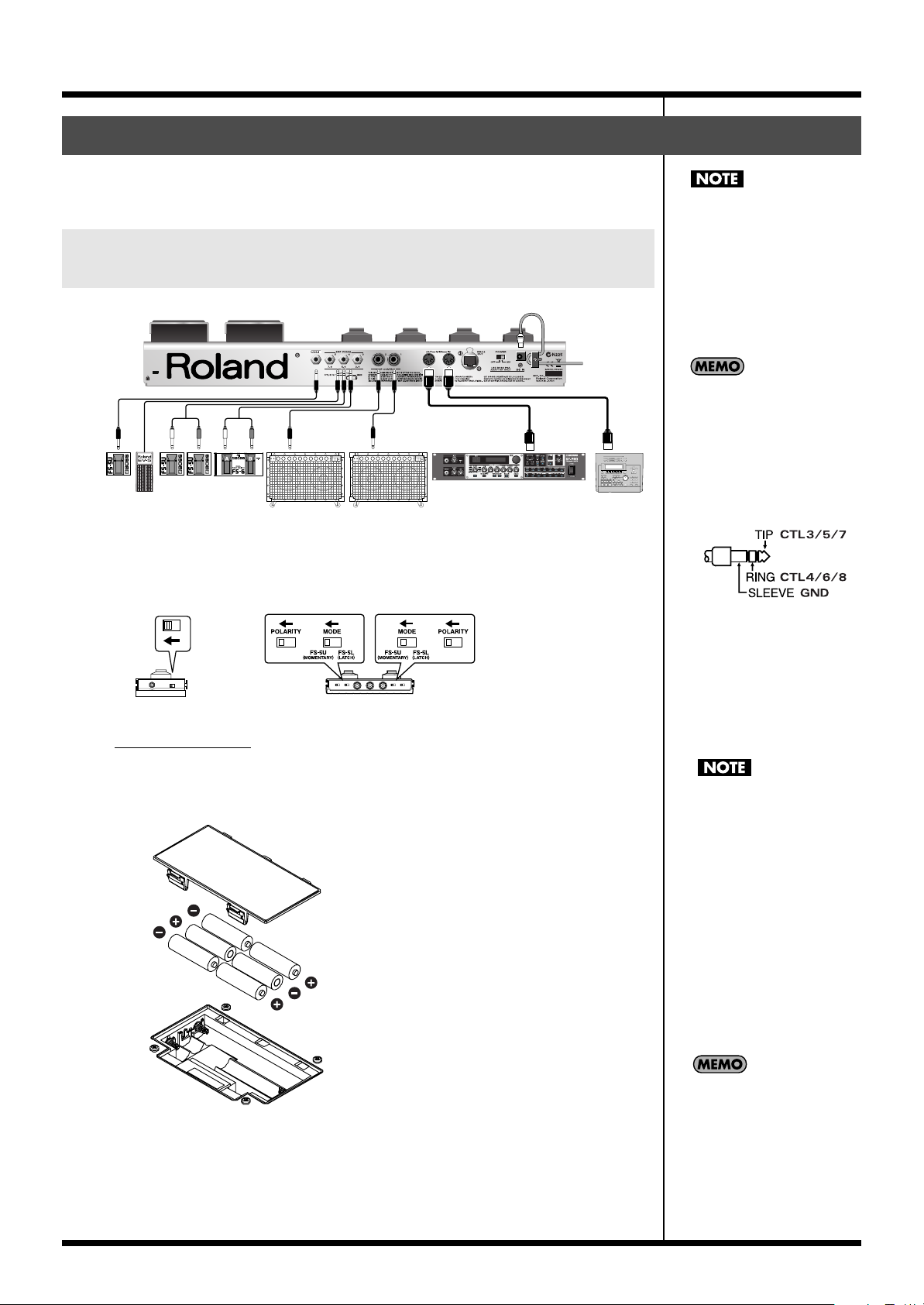
fig.
AC Adaptor
BOSS PSA series
PCS-31PCS-31
White RedWhite Red
BOSS
FS-5U
EV-5 etc.
BOSS
FS-5U
BOSS
FS-5U
BOSS
FS-6
If you want to use a footswitch for changing the mode, be sure to connect a BOSS FS5U/FS-6 footswitch (Optional) to the MODE jack.
When using the FS-5U or FS-6, set the polarity switch as shown below.
fig.FS-5U.eps
Connect to footswitch jack
Guitar Amp etc.
External Sound Module
MIDI IN
MIDI OUT
MIDI Sequencer etc.
Introduction
921
Before connecting other
devices, always be sure to turn
down the volume on all
devices and turn off their
power to prevent malfunction
and damage to the speakers (or
other components) of
connected devices.
922
This instrument is equipped
with 1/4 inch TRS phone type
acks. Wiring diagrams for
these jacks are shown below.
Make connections after first
checking the wiring diagrams
of other equipment you intend
to connect.
fig.XLR/TRSJack.eps
Install batteries
The FC-300 is not loaded with batteries when purchased.
When running the FC-300 on battery power, install the batteries using the following figure.
fig.change-battery.eps
• When turning the unit
upside-down, get a bunch of
newspapers or magazines,
and place them under the
four corners or at both ends
to prevent damage to the
buttons and controls. Also,
you should try to orient the
unit so no buttons or
controls get damaged.
929
• When turning the unit
upside-down, handle with
care to avoid dropping it, or
allowing it to fall or tip over.
When the battery power
egins to run low, “Battery
Low!” appears in the display.
When this occurs, replace with
new batteries as soon as
possible.
Pressing [EXIT] clears the
message from the display.
11
Introduction
925
Use only the specified
expression pedal (Roland EV-
5, BOSS FV-500L/FV-500H;
each sold separately). By
connecting any other
expression pedals, you risk
causing malfunction and/or
damage to the unit.
Carefully connect the RRC2
cable or Ether cable all the way
in—until it is firmly to the
RRC2 connector.
Ethernet cables designed for
crossover connections cannot
be used.
Do not subject the RRC2 cable
and the Ether cable to stress or
physical shock.
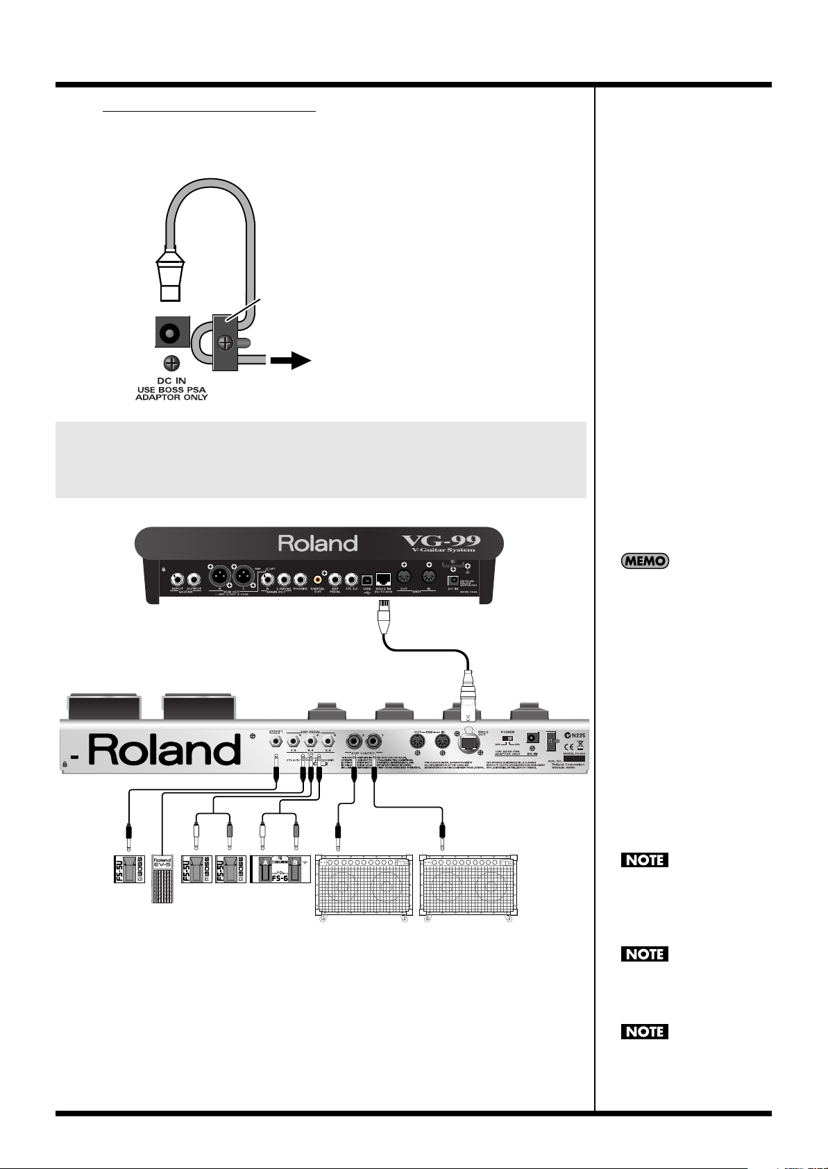
PCS-31PCS-31
Connect to footswitch jack
RRC2 cable
RRC2 IN device
EV-5 etc.
Guitar Amp etc.
BOSS
FS-6
BOSS
FS-5U
BOSS
FS-5U
BOSS
FS-5U
White RedWhite Red
Connecting an AC Adaptor
If you’re using a BOSS PSA series AC adaptor, here’s how to connect the cord and
secure it on the cord hook.
fig.CordHook.j.eps
The cord of
the supplied AC Adaptor
Cord Hook
To the Power Outlet
Connections To Make When Using the FC-300 as a
Dedicated Foot Controller for an RRC2 IN Device
(e.g., the VG-99)
fig.
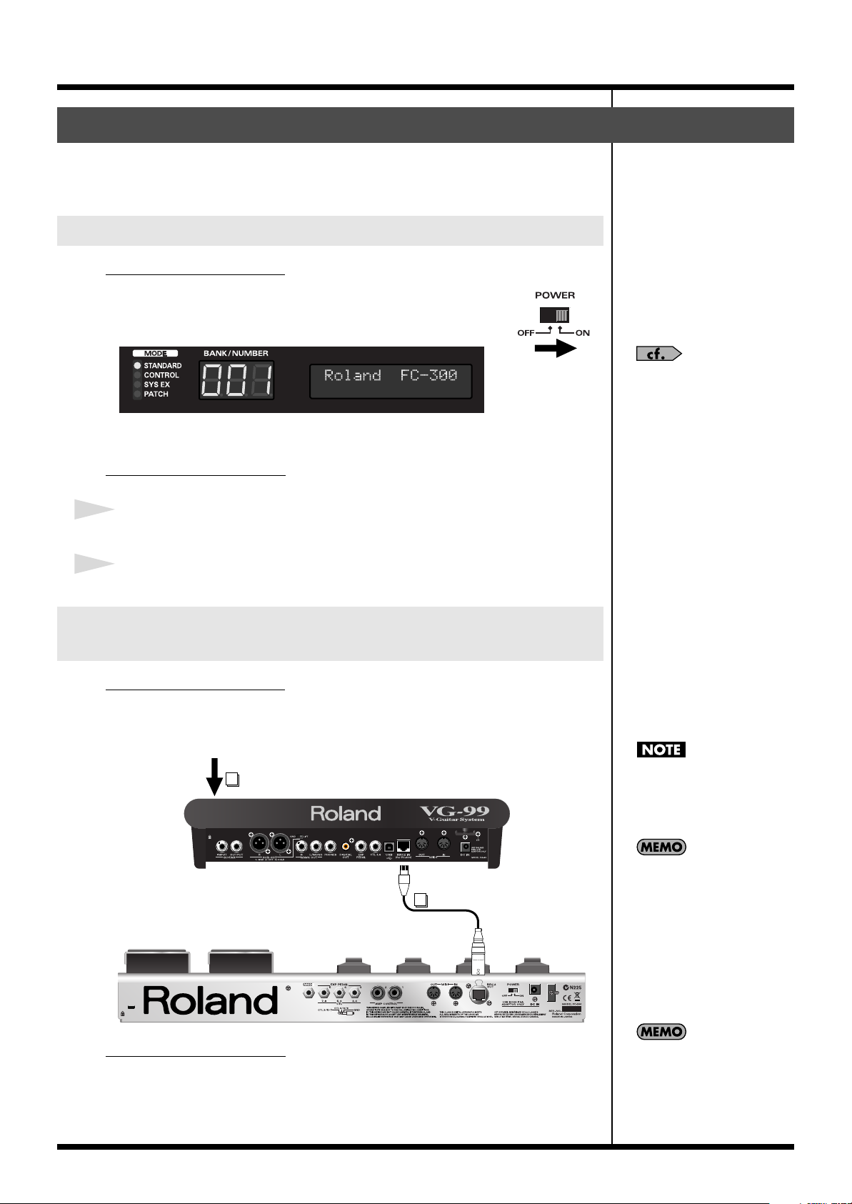
* Power is supplied from the RRC2 IN device, so no batteries or AC adaptor is necessary.
* If using commercially available ethernet cable as the RRC2 connecting cable, be sure that
the cable meets the following specifications.
• Category 5 (Cat5) or above
• Maximum length of 15 meters
12
• Cable designed for straight-through connections
Turning the Power On and Off
Once the connections have been completed (p. 11), turn on power to your various
devices in the order specified. Turning on devices in the wrong order may cause
malfunction or damage to the speakers (or other components) of connected devices.
When Using the FC-300 as a MIDI Foot Controller
Turning On the Power
fig.power-on.eps
First, check that you are connected properly with the external MIDI
instrument. Then set the power switch on the FC-300 to “ON.”
fig.
When the power is turned on, the FC-300 starts up in Standard Mode.
Turning Off the Power
Introduction
In addition, it starts up with
the MIDI channel set to “1,”
ut you can change the startup
MIDI channel if you want.
Refer to “Setting the MIDI
Transmit Channel”
(p. 52).
1
Switch off the power to the device connected to the FC-300.
2
Set the FC-300’s POWER switch to OFF.
When Using the FC-300 as a Dedicated Foot
Controller for an RRC2 IN Device (e.g., the VG-99)
Turning On the Power
First, check that you are connected properly with the RRC2 IN device. Then set the
power switch on the RRC2 IN device to “ON.”
fig.
2
Turn on the power of RRC2 IN device.
1
Connect the RRC2 cable.
Carefully connect the RRC2
cable or Ether cable all the way
in—until it is firmly to the
RRC2 connector.
When the RRC2 IN device’s
POWER switch is set to ON,
the FC-300’s power switches
on automatically, regardless of
the position of the FC-300’s
POWER switch.
Turning Off the Power
Switch off the power to the RRC2 IN device connected to the FC-300.
Although the FC-300 starts up
in Standard Mode, it may be
switched to a different mode
y means of settings received
from an RRC2 IN device.
13

Introduction
About the MODES
The FC-300 features the following four modes. The pedals function differently
depending on the mode that’s selected.
This manual describes each mode separately, while explaining the items available in
a particular mode.
Standard Mode (p. 16)
This mode is for sending Program Change messages and Control Change messages.
You can use the pedals to send any Program Change messages.
Control Change Mode (p. 21)
This mode is for sending Control Change messages.
You can use this mode to send the Control Change messages assigned to the pedals,
and enhance the expressiveness of a performance.
You can also store up to five sets, or configurations, of settings for all of the pedals
(Pedal Setting function).
See “Switching Modes” (p.
15) for an explanation of how
to choose a mode.
System Exclusive Mode (p. 28)
This mode is for sending System Exclusive messages.
You can use this mode to operate other equipment that accepts SysEx messages sent
from the FC-300.
Patch Mode (p. 29)
This mode is for transmitting multiple MIDI messages (MIDI streams) already saved
to patches.
Patches are areas of memory in which MIDI streams are stored; you can save up to
100 patches.
An individual patch can hold MIDI messages containing up to a maximum of
approximately 500 bytes.
Using Patch Mode, you can transmit groups of MIDI messages through one patch,
which allows you to switch the settings of multiple devices all at once.
14
Switching Modes
You can change the way the
mode is switched when using
[ ] and [ ] pedal or
footswitch. See
“Switching
the Function of the MODE
Pedal Jack” (p. 51) for the
details on how to do this.
Standard Mode
Control Change Mode
System Exclusive Mode
Patch Mode
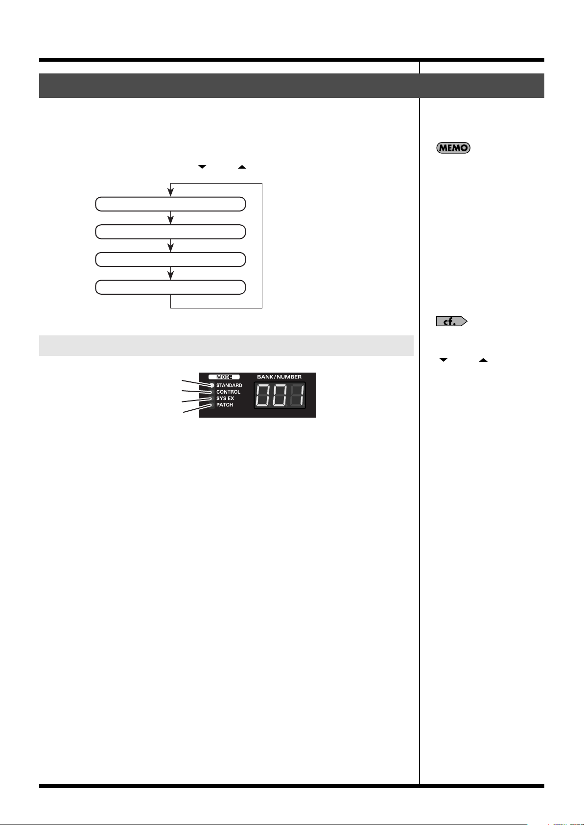
You can switch modes using one of the following methods.
• Press [MODE]
• Press a footswitch (BOSS FS-5U/FS-6; sold separately) connected to the MODE
jack
• Simultaneously press the [ ] and [ ] pedals
fig.
Standard Mode
Control Change Mode
System Exclusive Mode
Patch Mode
Introduction
The explanations in this
manual include illustrations
that depict what should
typically be shown by the
display. Note, however, that
your unit may incorporate a
newer, enhanced version of the
system, so what you actually
see in the display may not
always match what appears in
the manual.
About the Mode Indicators
The current mode is indicated with the MODE indicators. You can switch modes
only from the top screen of any mode.
15
Standard Mode
• With the factory settings,
Program Change messages
are not transmitted just by
pressing the [ ] and
[ ] pedals. To transmit
Program Change messages
just by pressing the [ ]
and [ ] pedals, read
“Using the [ ] [ ]
Pedals to Make the
Settings” (p. 48).
• You can press the [ ] or
[ ] pedal to change
patch numbers ten at a
time. For more detailed
information, see
“Setting
the [ ] [ ] Pedal
Step Size”
(p. 49).
• You can limit the range of
numbers switched. For
more detailed information,
see
“Limiting the Range of
Banks That Can Be
Switched (Bank Extent)”
(p. 48).
• You can indicate the pedal
bank and number
separately in the BANK/
NUMBER display. For
details, refer to
This is the mode for sending Program Change messages and Control Change
messages.
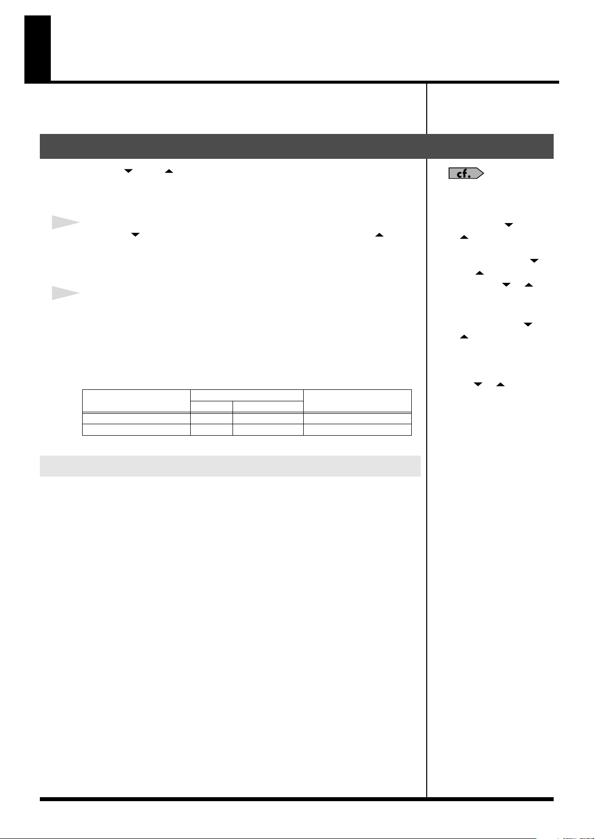
Transmitting Program Change Messages
Pressing [ ] and [ ] pedals and the number pedals (1/6 – 5/10) transmits the
Program Change messages and Bank select messages for the corresponding number
pedals.
1
Press the [ ] pedal, and the numbers decrease by five; press the [ ]
pedal, and the numbers increase by five.
The BANK/NUMBER display and Number pedal indicators flash.
Setting How Tones are Switched
Press the number pedal (1/6–5/10) to select the number.
The indicator for the number pedal pressed lights, and the Program Change message
is transmitted.
With the factory settings, transmission of Bank Select messages and Program
Change messages is in accordance with what is indicated in the BANK/NUMBER
display, as shown below.
BANK/NUMBER Display
001–128
129–130 1 0 29–30
You can set the way the FC-300 switches tones with the pedals and displays tone
numbers.
Make the settings to match the specifications of the external MIDI devices you are
using (p. 47).
2
Bank Select Message
(MSB) (LSB)
0 0 1–128
Program Change Message
“Setting
How Numbers are
Indicated” (p. 49).
• You can stop output of
Bank Select messages. For
details, refer to “Setting
the Bank Select Output”
(p. 52).
• You can change the Bank
Select messages. For details,
refer to “Setting the Bank
Select Value” (p. 53).
16
Transmitting Control Change Messages
The Control pedal is a
momentary type pedal that
sends an ON message when
depressed and an OFF
message when released. You
can change this to latch type
operation, which sends an ON
or OFF message each time you
depress it – see
“Mode” (p. 20).
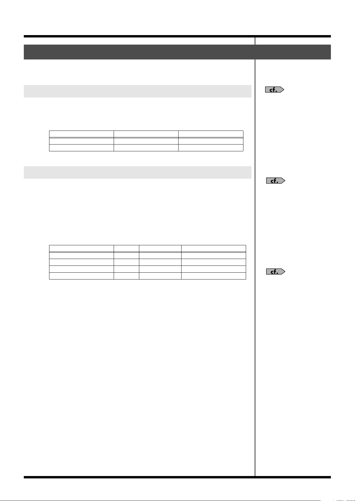
You can transmit Control Change messages with expression pedals and control
pedals.
Standard Mode
Using the Expression Pedals
In keeping with the movement of the expression pedal, Control Change messages
with the controller numbers set for each pedal are transmitted consecutively.
Each pedal is set at the factory as shown below.
Expression Pedal
EXP PEDAL 1
EXP PEDAL 2 1 0–127
CC# Range
7 0–127
Using the Control Pedal and Expression Pedal Switch
When you use control pedals, you can use the control pedals to send the Control
Change messages for the controller numbers assigned to each of the pedals.
In addition, you can activate the expression pedal switch by strongly pressing down
on the toe end of the pedal.
Control Change messages with the controller numbers set for each pedal are
transmitted.
Each pedal is set at the factory as shown below.
Pedal
CTL PEDAL 1
CTL PEDAL 2 81 0–127 LATCH
EXP PEDAL SW 1 82 0–127 LATCH
EXP PEDAL SW 2 83 0–127 LATCH
CC# Range Mode
80 0–127 LATCH
For details about the all
parameters and changes the
setting, refer to “Change the
Pedal Settings” (p. 19).
You can use the control pedal
and expression pedal switch to
switch the AMP CONTROL
acks – see “Change the Pedal
Settings” (p. 19).
17
Standard Mode
Using the External Control Pedals and Expression Pedals
You can connect separately available footswitches and expression pedals and use the
external pedals just like the FC-300’s pedals to transmit Control Change messages,
Realtime messages, and other such data.
For details about the all
parameters and changes the
setting, refer to “Change the
Pedal Settings” (p. 19).
When a BOSS FS-5U, FS-6 Footswitch is Connected,
Assigned to CTL Pedal:
These function in the same way as the FC-300’s built-in control pedals.
Connect a control pedal to the EXP PEDAL/CTL jack and set the FC-300 to enable
use of the pedal. (p. 50)
* If you have two FS-5U pedals or an FS-6 pedal connected to the CTL3,4 jack with a special
PCS-31 connecting cable (from Roland; available separately), the footswitch connected to
the plug with the white ring controls the setting of CONTROL 3, and the footswitch
connected to the plug with the red ring controls the setting of CONTROL 4.
* When only one footswitch is connected to the CTL3,4 jack, the CONTROL 3 settings are
enabled.
* When an FS-6 is connected to the CTL3,4 jack with an optional connection cable
(stereo 1/4” phone ←→ stereo 1/4” phone), pedal switch B operates according to the
CONTROL 3 settings, and pedal switch A operates according to the CONTROL 4
settings.
See “Making the
Connections” (p. 11) for
instructions on setting the
polarity switch and mode
switch for the connected pedal.
When a Roland EV-5, BOSS FV-500L or FV-500H is
Connected, Assigned to Expression Pedal:
These function in the same way as the FC-300’s built-in expression pedals.
Connect a expression pedal to the EXP PEDAL/CTL jack and set the FC-300 to
enable use of the pedal. (p. 50)
* These do not operate as expression pedal switches.
* If you are connecting a BOSS FV-500L/FV-500H, connect the pedal with an optional
←→
connection cable (stereo 1/4” phone
stereo 1/4” phone).
Controller Numbers for Each Pedal
Each pedal is set at the factory as shown below.
Pedal
CTL3
CTL4 75 0–127 LATCH
CTL5 10 0–127 LATCH
CTL6 91 0–127 LATCH
CTL7 11 0–127 LATCH
CTL8 64 0–127 LATCH
EXP PEDAL 3 76 0–127 EXP PEDAL 4 10 0–127 EXP PEDAL 5 11 0–127 —
CC# Range Mode
76 0–127 LATCH
For details about the all
parameters and changes the
setting, refer to “Change the
Pedal Settings” (p. 19).
18
Change the Pedal Settings
You can freely change the settings for each pedal.
1
In the Standard Mode’s top screen, press PARAMETER [ ].
2
Press PARAMETER [ ] [ ] to display the pedal setting screens.
3
Press VALUE [ ] [ ] to change the value.
Standard Mode
MIDI Messages
This selects the MIDI messages to be transmitted.
fig.05-009
• OFF
These do not output MIDI messages.
• CC#1–CC#31, CC#33–CC#95
These output Control Change messages.
When the pedal is used as an expression pedal, consecutive values are output within
the range set with the Range setting. When the pedal is used as a control pedal or
other type of switch, the maximum value is output when the switch is on, and the
minimum value is output when the switch is off.
• MIDI START / MIDI STOP / MIDI CONTINUE / MMC STOP / MMC PLAY /
MMC DEF PLAY / MMC FAST FWD / MMC REWIND / MMC REC STROBE /
MMC REC EXIT / MMC REC PAUSE / MMC PAUSE
This transmits MIDI Realtime messages and MMC messages.
When assigned to an expression pedal, messages are output once the pedal is
pressed downward past the halfway point; when assigned to a control pedal or other
switch, the messages are output when the switch is on.
• P.BEND / CH.PRS
These transmit various Pitch Bend messages and Channel Pressure messages.
When assigned to an expression pedal, consecutive values are output within the
range set with the Range parameter. When assigned to a control pedal, the
maximum value is output when the switch is on, and the minimum value is output
when the switch is off.
19
Standard Mode
Range
This sets the range for values that are transmitted.
fig.05-009
Minimum Maximum
Mode
This sets the switch mode.
fig.05-009
Value
LATCH
MOMENTARY The value will be ON while you press the pedal, and OFF when you
Explanation
The ON and OFF will alternate each time you press the pedal.
release the pedal.
AMP Ctl Op (Amp Control Operation)
This selects whether or not the AMP CONTROL jack is to be controlled.
fig.05-009
The Range parameter is
enabled when CC#, P.BEND,
or CH.PRS is selected.
The Mode parameter and AMP
Ctl Op parameter are enabled
when a control pedal or other
switch function is selected.
This parameter is ignored
when the pedal is used as a
expression pedal.
AMP CONTROL
1 jack
AMP CONTROL
2 jack
When the AMP Ctl Op parameter is set to ON and the AMP Polarity parameter is set
to Normal, control of AMP CONTROL with the pedal functions as shown below.
fig.05-009
When the pedal is OFF
Guitar Amp
(amps channel switching jack)
When the pedal is ON
Guitar Amp
(amps channel switching jack)
Closed
FC-300
(AMP CONTROL jack)
Open
FC-300
(AMP CONTROL jack)
4
When you have finished making the settings, press [EXIT] to return to the
initial screen.
The settings are saved, and the FC-300 returns to the initial screen.
You can change the polarity of
the AMP CONTROL jacks. For
more detailed information, see
“Setting the Polarity of the
AMP CONTROL Jacks” (p.
50).
20
Control Change Mode
For details about the all
parameters and changes the
setting, refer to “Change the
Pedal Settings” (p. 24).
About the Control Change Mode
This is the mode for sending Control Change messages.
In this mode, all the pedals can be used to send Control Change messages. You
should use this mode at times when you want to send a lot of Control Change
messages.
Pedal Setting Number
You can also store up to five sets, or configurations, of settings for all of the pedals
within the FC-300’s memory. Called pedal settings, these configurations can be
switched as needed (p. 26).
Transmitting Control Change Messages
Pressing the various pedals transmits the Control Change messages set for the
respective pedal over the selected MIDI channel.
Number Pedal (1/6–5/10)
Control Change messages with the controller numbers set for each pedal are
transmitted.
Each pedal is set at the factory as shown below.
Pedal
1
2 66 0–127 LATCH 7 71 0–127 LATCH
3 67 0–127 LATCH 8 72 0–127 LATCH
4 68 0–127 LATCH 9 73 0–127 LATCH
5 69 0–127 LATCH 10 74 0–127 LATCH
CC# Range Mode Pedal CC# Range Mode
65 0–127 LATCH 6 70 0–127 LATCH
[ ] [ ] Pedal
These switch the number pedal functions.
Pedal
[]
[] This sets the number pedals to function as pedals 6–10.
Explanation
This sets the number pedals to function as pedals 1–5.
When the [ ] pedal is pressed, the [ ] pedal’s indicator lights, and the functions
for number pedals 1–5 become operable.
When the [ ] pedal is pressed, the [ ] pedal’s indicator lights, and the functions
for number pedals 6–10 become operable.
21
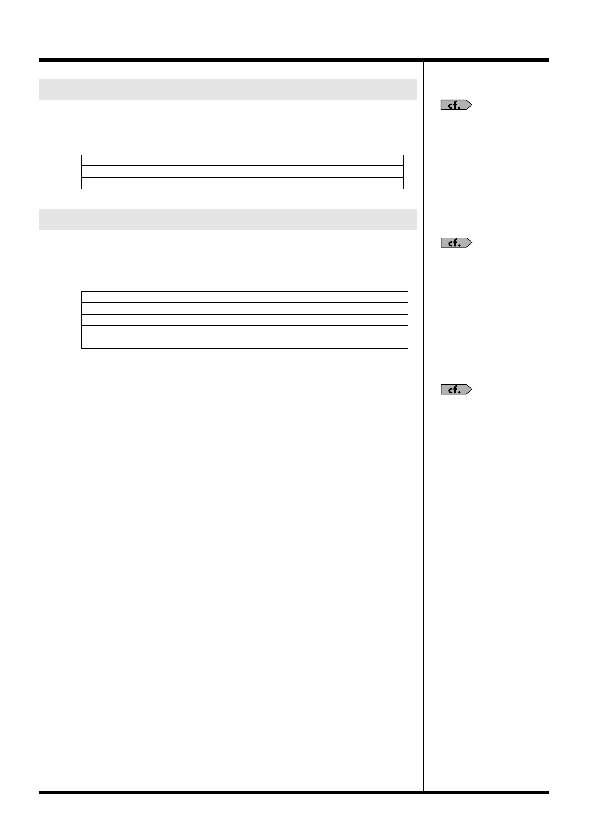
Control Change Mode
You can use the control pedal
and expression pedal switch to
switch the AMP CONTROL
jacks – see
“Change the Pedal
Settings” (p. 24).
Using the Expression Pedals
In keeping with the movement of the expression pedal, Control Change messages
with the controller numbers set for each pedal are transmitted consecutively.
Each pedal is set at the factory as shown below.
Expression Pedal
EXP PEDAL 1
EXP PEDAL 2 1 0–127
CC# Range
7 0–127
Using the Control Pedal and Expression Pedal Switch
Control Change messages with the controller numbers set for each pedal are
transmitted.
Each pedal is set at the factory as shown below.
Pedal
CTL PEDAL 1
CTL PEDAL 2 81 0–127 LATCH
EXP PEDAL SW 1 82 0–127 LATCH
EXP PEDAL SW 2 83 0–127 LATCH
CC# Range Mode
80 0–127 LATCH
For details about the all
parameters and changes the
setting, refer to “Change the
Pedal Settings” (p. 24).
The Control pedal is a
momentary type pedal that
sends an ON message when
depressed and an OFF
message when released. You
can change this to latch type
operation, which sends an ON
or OFF message each time you
depress it – see “Mode” (p. 25).
22
Loading…
Напольный MIDI контроллер FC-300 установил новый стандарт универсальности и мощных возможностей напольного педального управления MIDI-устройствами. Благодаря таким функциям, как двунаправленная передача MIDI данных на Roland VG-99 через недавно принятый стандарт RRС2*, вызов патчей из памяти, а также наличию двойной педали экспрессии и девяти педалей управлении и эта продвинутая станция управления идеально подходит для гитарной системы VG-99. Конечно же, ее можно использовать и с любыми другими MIDI инструментами или устройствами.
- Продвинутый напольный MIDI контроллер с двумя назначаемыми педалями экспрессии, двумя педалями управления, девятью ножными переключателями и возможностью расширения
- Новый режим Patch Mode, позволяющий сохранять до 100 MIDI установок
- В дополнение к стандартным MIDI соединениям принят новый разработанный протокол RRC2 для двунаправленной передачи данных между FC-300 и продукцией Roland, оснащенной RRC2
- Три варианта подачи питания (от батарей: 6 х АА, через АС адаптер, по RRC2) и прочная металлическая конструкция для использования в туровой работе
- Два переключателя Amp Control для управления каналами усилителя или эффектами
- Идеально подходит для использования с гитарной системой VG-99
* RRC2 – недавно принятый протокол для продукции Roland, позволяющий осуществлять двунаправленную передачу MIDI данных и подачу электропитания через кабель Lan (СAT5).
Управление и выразительность
FC-300 оснащен девятью ножными переключателями повышенной надежности и двумя программируемыми педалями экспрессии для быстрого и простого управления любыми параметрами. Эти возможности могут быть еще дальше расширены подключением дополнительных педалей (приобретаются отдельно).
Подсвечивающийся ЖК-дисплей обеспечивает высокую четкость при отображении названий патчей (при использовании с VG-99), а также других важных данных даже в условиях самого плохого освещения на сцене.
Энергия патчей
На FC-300 можно одновременно сохранять до 100 установок MIDI сообщений/параметров в виде патчей. Комплексная MIDI передача стала очень простой благодаря способности FC-300 запаковывать пакеты данных в один патч и передавать каждую очередную порцию данных при нажатии педали.
Широкие возможности коммутации
Принятый новый протокол RRC2 обеспечивает двунаправленную MIDI передачу данных и подачу питания с помощью соединения VG-99 и FC-300 всего одним проводом (Ethernet-кабель продается в любом компьютерном магазине).
Программируемое переключение
FC-300 содержит два гнезда для дополнительных многоцелевых педалей-переключателей. Педали, подключенные к этим выходам, позволяют удобно переключать каналы усилителя с clean на lead, синхронно с изменениям патча на FC-300.
СПЕЦИФИКАЦИЯ
Органы управления: Педаль х 5 (1/6, 2/7, 3/8, 4/9, 5/10), педали DOWN/UP, педали управления (CTL 1, CTL 2), педали экспрессии (EXP PEDAL 1, EXP PEDAL 2), кнопки PARAMETER (левая, правая), кнопки VALUE (вверх, вниз), кнопка UTILITY, кнопка MODE, кнопка EXIT, кнопка WRITE, кнопка сетевого выключателя POWER.
Дисплей: 3-цифры, и 2-строчный по 16 символов в строке (ЖК с подсветкой)
Индикаторы: Индикатор MODE (STANDARD, CONTROL, SYS EX, PATCH), индикатор UTYLITY, индикатор WRITE, цифровые индикаторы (1 – 10), индикаторы DOWN/UP, индикаторы Control (1, 2), индикаторы педалей экспрессии ON/OFF (1, 2)
Коммутация: гнездо подключения АС адаптера (DC IN), разъемы MIDI IN, MIDI OUT, разъем RRC2 OUT, разъем AMP CONTROL 1, разъем AMP CONTROL 2, разъем подключения педали экспрессии 3/CTL4, 4; разъем подключения педали экспрессии 4/CTL5, 6; разъем подключения педали экспрессии 5/CTL 7, 8; разъем MODE
Питание: 9 В постоянного тока: от адаптера (серии PSA), от батареек типа AA (угольные) х 6 или LRS (AA) типа (щелочные) х 6, RRC2 (подключение от RRC2)
Габариты Ширина: 55,0 см Глубина: 25,0 см Высота: 7,6 см Вес: 5.2 кг (без АС адаптера и батарей)
В комплекте Руководство пользователя, сухие батареи RS (AA) типа (угольные) х 6 Дополнительно поставляется АС адаптер серии PSA (BOSS), ножной переключатель: FS-5L (BOSS), FS-6 (BOSS), педаль экспрессии: EV-5, FV-500H (BOSS), FV-500L (BOSS)
* Технические данные могут изменяться без предупреждения.
Страница на сайте производителя