
716808
В этой статье мы подробно рассмотрим процесс подключения и настройки двух отличных моделей роутеров от компании TP-LINK. Это модель TL-WR940N и TL-WR941ND. Я не вижу смысла писать для каждой модели отдельную статью, так как TL-WR941ND и TL-WR940N практически одинаковые по внешнему виду и по разъемам. Так же, у них одинаковые панели управления. Отличие только в том, что у роутера TL-WR940N не съемные антенны, ну и скорее всего есть отличие в железе. Для нас это не очень важно.

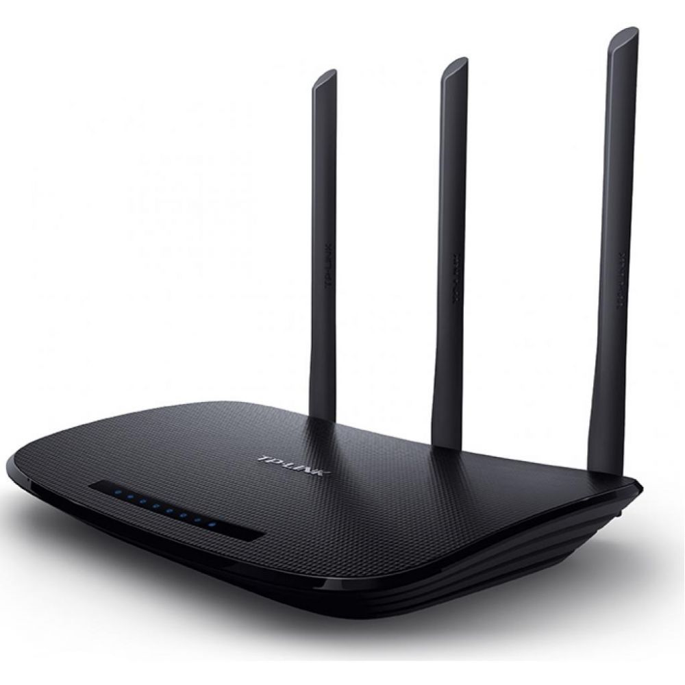
Кстати, недавно появилась обновленная модель роутера, в черном корпусе. Не важно, какая у вас модель, вы сможете настроить ее по этой инструкции. Я постараюсь максимально подробно и понятно все расписать. Настраивать мы будем через панель управления. Поэтому, диск, который вы скорее всего нашли в комплекте, можете оставить. Он нам не пригодится. На нем есть только утилита для настройки, и руководство. Можете попробовать настроить маршрутизатор с помощью утилит, но я бы советовал делать это через WEB-интерфейс.
Несколько советов перед настройкой:
Я рекомендую подключать роутер к компьютеру, или ноутбуку по сетевому кабелю, который вы найдете в комплекте. Только для настройки. Проводить настройку лучше по кабелю. После настройки, вы сможете отключить сетевой кабель.
Если нет возможности подключится по LAN, то можно настроить и по Wi-Fi. Просто подключитесь к незащищенной сети, которая должна появится сразу после включения маршрутизатора. Не прошивайте роутер по Wi-Fi! Только по кабелю.
Возможно, что роутер уже пробовали настроить. Либо вы, либо в магазине. Те настройки, которые уже возможно там указаны, могут нам помешать. Я советую сделать сброс настроек на вашем TL-WR940N, или TL-WR941ND перед там, как приступать к настройке.
Включите роутер в розетку. Убедитесь, что индикаторы на устройстве загорелись. Если нет, то включите питание специальной кнопкой на задней панели.
Нажмите, и секунд 10 подержите кнопку RESET на задней панели роутера.
Если там кнопка утоплена в корпус, то нажмите на нее чем то острым. Например, скрепкой.
Все индикаторы на передней панели должны мигнуть. Это значит, что произошел сброс настроек.
Подробнее о восстановлении заводских настроек на маршрутизаторах TP-LINK, вы можете почитать в этой статье.
Все, можно преступать к настройке.
Как подключить TL-WR940N/TL-WR941ND?
Для начала, нам нужно все соединить.
Подсоедините антенны (если они съемные).
Подключите к роутеру кабель питания и включите его в розетку.
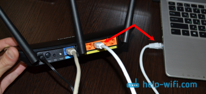
В один из желтых разъемов подключите сетевой кабель, который был в комплекте. Второй конец кабеля подключите к компьютеру в сетевой разъем. Если вы будете настраивать по Wi-Fi, то подключите свой ноутбук к открытой сети, которая по умолчанию называется примерно так: «TP-LINK_37DE50». Можете отключить питание на маршрутизаторе, если сеть пропадет, значит ваша.
Если заводская беспроводная сеть закрыта паролем (в обновленной модели), то сам стандартный пароль от Wi-Fi указан снизу роутера на наклейке.
В синий разъем (WAN) подсоедините кабель от вашего интернет-провайдера (или, например, от ADSL модема).
Вот картинка для наглядности:

B фото подключения обновленной модели TP-LINK TL-WR940N (в черном корпусе):
Подключили? Продолжаем.
Настройка TP-LINK TL-WR940N (TL-WR941ND)
Откройте на компьютере (к которому вы подключили наш TP-LINK TL-WR940N, или 941ND) любой браузер. Opera, Chrome, Internet Explorer – не важно.
В адресной строек браузера наберите адрес http://192.168.1.1 и перейдите по нему.
В обновленной версии (которая в черном корпусе), для доступа к настройкам используйте адрес tplinkwifi.net, или 192.168.0.1.
Должен появится запрос логина и пароля. По умолчанию, это admin и admin (эту информацию можно посмотреть на наклейке снизу маршрутизатора).
Введите их, и войдите в панель управления. Или смотрите подробную инструкцию по входу в настройки на Tp-Link.

Должна открыться панель управления роутером TP-LINK.
Советуем вам перед настройкой проверить прошивку на которой работает роутер. И, если есть новая, то прошить роутер. Как найти и скачать прошивку для TP-LINK, читайте в этой статье. Инструкция по прошивке находится здесь. Если не желаете обновлять ПО, то продолжайте настройку по инструкции.
Настройка WAN
Это самый важный этап настройки. Нам нужно настроить роутер, что бы он смог подключатся к провайдеру и раздавать интернет на ваши устройства. Если мы укажем неправильные настройки на вкладке WAN, то интернет через роутер работать не будет.
Ваши устройства будут просто подключаться к Wi-Fi сети от TL-WR940N, или TL-WR941ND, но интернет работать не будет. Поэтому, здесь нужно все сделать очень внимательно.
Главное, вам нужно узнать технологию соединения, которую использует ваш интернет-провайдер. Скорее всего, это: Динамический IP, Статический IP, PPPoE, L2TP, PPTP и т. д. Так же, вам нужно узнать, делает ли провайдер привязку к интернету по MAC адресу.
Всю это информацию вы можете узнать у поддержки вашего интернет-провайдера, на их сайте, или в договоре, который вам должны были дать при подключении.
Давайте на всякий случай клонируем MAC адрес с компьютера, к которому был привязан интернет. Если вы точно знаете, что ваш провайдер не делает привязку по MAС, то можете пропустить этот пункт. Инструкция под спойлером:
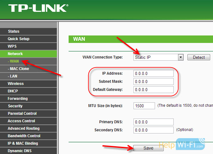
Перейдите на вкладку Network — WAN, и напротив пункта WAN Connection Type выберите технологию соединения, которую использует ваш провайдер.
Динамический IP
Если ваш интернет-провайдер использует технологию соединения Динамический IP (скорее всего так и есть, это очень популярная технология), то выберите ее «Dynamic IP«, и интернет сразу должен заработать. Но лучше все сохранить, нажав на кнопку Save и перезагрузить роутер.

Настройки для других технологий соединения:
Статический IP
Выбираем Static IP, указываем IP, который нам выдал провайдер и нажимаем кнопку Save для сохранения настроек.
PPPoE
Выберите PPPoE, и ниже укажите нужные параметры, которые вам выдал провайдер: логин, пароль, возможно еще IP адрес.

L2TP или PPTP
Выбираем одну из технологий, и задаем нужные параметры. Для сохранения настроек не забудьте нажать кнопку Save.

Если вы правильно укажите тип соединения, то интернет должен сразу заработать. Сохраните настройки, и перезагрузите роутер. Перезагрузить можно из панели управления System Tools — Reboot, кнопка Reboot. После перезагрузки, интернет на компьютере уже должен работать.
Возле значка сети, уже должен пропасть желтый треугольник, и статус соединения должен быть «Доступ к интернету«. Если интернет через TL-WR941ND так и не заработал, то проверяйте настройки на вкладке WAN, скорее всего, вы там допустили ошибку. Проверьте, правильно ли клонировали MAC адрес (если нужно).
Если вы раньше на компьютере запускали какое-то соединение (высокоскоростное соединение), то его можно удалить.
Настройка Wi-Fi, установка защиты на сеть
Перейдите на вкладку Wireless — Wireless Settings.
Укажите имя для вашей Wi-Fi сети, и выберите в списке свой регион.

Дальше перейдите на вкладку Wireless — Wireless Security. Установим пароль на Wi-Fi, что бы к нашей сети никто не смог подключится.
Выделяем пункт WPA/WPA2 — Personal(Recommended). В поле Wireless Password, указываем пароль. Я рекомендую указать ровно 8 символов. Английские буквы и цифры.

Нажмите снизу на кнопку Save, что бы сохранить настройки.
Сменить пароль на Wi-Fi вы сможете в любой момент. Но, устанавливать его я советую стразу в процессе настройки роутера.
Настройка даты, установка защиты на панель управления
На вкладке System Tools — Time Settings укажите правильный часовой пояс, дату и время. Не забудьте сохранить настройки.
Дальше перейдите на вкладку System Tools — Password.
Здесь мы изменим стандартные логин/пароль, которые используются для входа в настройки роутера.
В поле Old User Name и Old Password укажите данные по умолчанию admin и admin. А в полях ниже, укажите новый логин (можете оставить admin), и пароль, придумайте свой. Обязательно запишите пароль на бумажку.
Подробнее о настройке защиты панели управления написано в этой статье.

Вот и все, осталось только перезагрузить TP-LINK TL-WR940N, или TL-WR941ND, если вы настраивали его, и можно подключать к интернету свои устройства: ноутбуки, компьютеры, планшеты, телефоны, телевизор и т. д.
Если у вас в процессе настройки роутера возникли проблемы, то напишите о них в комментариях, постараемся помочь разобраться в вашей проблеме.
Специалист техподдержки, PHP-программист, разработчик WordPress
Задать вопрос
Флагман сетевого оборудования – компания Tp-Link – обычно не беспокоится по поводу названий своих новых разработок. Она выпустила уже шесть реинкарнаций популярной модели Tp-Link TL-WR940N 450m, по настройке которой у пользователей возникает много вопросов. Масла в огонь подливает ещё линейка WR940ND, которая тоже недавно отметила своё шестое перерождение. Итак, что же такое WR940N в шестом исполнении и с чем её едят?
Содержание
- Особенности и технические характеристики
- Индикаторы и разъёмы
- Подключение
- Вход в настройки роутера
- Автоматическая настройка
- Ручная настройка
- Настройка через мобильное приложение
- Подключение и параметры Wi-Fi
- Режим повторителя
- Настройка IPTV
- Смена пароля
- Обновление прошивки
- Сброс настроек
- Отзывы
Особенности и технические характеристики
Обзор версии начнём с её отличий от старших «однофамильцев». Их не очень много. Основные изменения WR940N v6 касаются внешнего оформления, небольшой экономии на деталях, а также (в последних прошивках) интерфейса настроек, выполненного в нежно-голубых тонах.

Но есть и две ключевые особенности:
- Первая – режим репитера (повторителя сигнала). Эту особенность оценят те, кому часто приходилось докупать отдельные девайсы для усиления или расширения зоны действия сети основного беспроводного маршрутизатора. Раньше Tp-Link предпочитал для этих целей выпускать отдельные устройства.
- Вторую включили в само название устройства. Маршрутизатор Tp-Link WR940N имеет символы 450m, что по заявлениям разработчиков указывает, что скорость связи у нового прибора должна достигать 450 Мбит/с.
На фоне этого довольно архаично смотрятся порты для проводного подключения со скоростью всего в 100 Мбит/c, их у модели пять (4 для домашних устройств, 1 для провайдера).
Вопросы вызывает также то, что модель по-прежнему не поддерживает стандарт 802.11ас, хотя у компании есть разработки с его поддержкой.
Основные характеристики:
- Стандарт Wi-Fi: 802.11 b, a, g, n;
- Частотный диапазон Wi-Fi: 2.4 ГГц;
- Мощность передатчика – 20 дБм;
- Размеры 230x35x144 мм;
- Поддержка 3 режимов работы: роутер, усилитель сигнала, точка доступа.
Новый аппарат выполнен в чёрных тонах, верхняя крышка слегка вогнута и, по традиции, имеет три несъемные антенны, которые для работы нужно отогнуть и повернуть в вертикальное положение.
По отзывам пользователей, пластик верхней панели маркий, собирает «пальчики».
Другая особенность, которой может «похвастаться» wi-fi роутер шестого поколения, – отсутствие ушек на нижней крышке (то есть маршрутизатор нельзя крепить на стену) и экономия на резине. Лапки для установки на стол у девайса есть, но выполнены они из пластика.
Удобство и простота настройки
10
Индикаторы и разъёмы
Традиционно на верхней крышке расположен ряд индикаторов, а также большие буквы названия бренда. И хоть количество и расположение индикаторов осталось неизменным, создавая новую версию, разработчики переделали схему их работы. Режим мигания больше не поддерживается, индикаторы горят голубым цветом (если подключённые к портам устройства работают и режимы не отключены в веб-интерфейсе), а индикатор WAN получил две возможности:
- в нормальном режиме работы он, как «соседи», горит синим цветом;
- если кабель подключен, но связи с провайдером нет, цвет становится оранжевым.
Естественно, если с кабелем проблемы или он не подключен, не горит вовсе.

Роутер TL-WR940N имеет 8 индикаторов:
- Питание;
- Wi-Fi;
- 4 индикатора по количеству портов для проводного соединения;
- подключение к интернету;
- WPS.
Задняя панель модели тоже стандартна:

После первой антенны:
- Разъем для блока питания;
- Кнопка включения;
- Сброс на заводские установки;
- WPS;
- Синий порт для соединения с провайдером.
После центральной антенны – 4 порта для подсоединения проводных устройств.
Подключение
Особых проблем подключение роутера не вызывает.

Как правило, процесс стандартен:
- Поставляемым в комплекте кабелем соедините одно их жёлтых гнёзд (LAN) с гнездом компьютера;
- Подсоедините кабель провайдера к синему гнезду (WAN);
- Подключите ТВ-приставку (если есть);
- Включите питание роутера.
Если всё верно, то после загрузки роутер покажет синим индикатором, что он работает, что компьютер подключен и что кабель провайдера включен. Но выйти в сеть роутер пока не может.
Вход в настройки роутера
Для того, чтобы настроить роутер, понадобится любой веб-браузер, имеющийся на компьютере пользователя.
Tp-Link продвигают также своё приложение для настройки, но, по отзывам пользователей, у шестой ревизии оно позволяет управлять уже настроенным роутером. Первоначальную настройку при его помощи сделать не получится.
Далее в адресной строке вводится хорошо известный адрес 192.168.0.1 и подтверждается нажатием «Ввод». В предыдущих ревизиях адрес был 192.168.1.1. Можно также воспользоваться специальным адресом, который Tp-Link предлагает всем владельцам своих роутеров — tplinkwifi.net.
Роутер предлагает ввести пароль для входа в настройки (заводской вариант — admin в оба поля).

Указав нужные данные, подтверждают действие нажатием ввода.
Автоматическая настройка
Первый вход в систему активизирует мастера, который предлагает настроить роутер Tp-Link TL-WR940N, подключиться к интернету и даже поднять беспроводную сеть.

Здесь же указывается, что можно либо согласиться с предложением, нажав «Далее», либо отказаться и перейти к ручной настройке нажатием «Выход».
Так как вернуться к быстрой настройке можно в любой момент, нажав кнопку в левом меню, нажимают «Выход». Роутер показывает сводную страницу настроек по умолчанию.

Справа можно почитать, что на странице отображается и за что отвечает каждая настройка. Возврат в меню быстрой настройки — вторая кнопка сверху в левом блоке.
Ручная настройка
Если пользователь решил делать все вручную, для этого надо переходить в блок «Сеть» левого меню. Здесь сразу открывается настройка WAN — соединения с провайдером.

Из списка в верхней части открывшейся страницы выбирают PPPoE/PPPoE Россия. Если провайдер использует другую схему, нужно выбрать соответствующую. Уточнить это можно в договоре или в ТП поставщика. Чуть ниже вводят имя и пароль подключения. Последний при этом нужно ввести дважды — для контроля. Дальнейшие настройки можно не трогать, выставив, как указано на картинке выше.
Проверяют правильность нажатием кнопки «Подключить». Если все настроено правильно, то роутер попробует соединиться с провайдером. На этом настройка интернета на роутере Tp-Link TL-WR940N завершается.
Настройка через мобильное приложение
Для настройки TL-WR940N через мобильный гаджет понадобится установить на него специальное приложение TP-Link Tether. Получить его можно в магазинах App Store или Google Play Market (выбор версии роутера особой роли не играет, так как, по заявлениям инженеров компании, приложение работает со всеми их современными устройствами).
После установки, активации, авторизации в приложении пользователь попадает в интерфейс настройки. Экран достаточно продуман — ничего лишнего.
Подключение и параметры Wi-Fi
Настройка беспроводной сети Wi-Fi на Tp-Link TL-WR940N довольно проста. При выборе блока «Беспроводной режим» в настройках открывается страница, на которой нужно указать имя сети (под этим именем роутер будет показываться всем устройствам).

Остальные настройки на странице можно не трогать или установить, как на картинке. Обратите внимание, что галочка «Включить беспроводное вещание» должна быть включена. Её отключение блокирует доступ всем беспроводным устройствам.
В варианте «из коробки» защиты сети нет. Поэтому нужно перейти на страницу «Защита беспроводного режима» и провести тут несколько настроек.

В большинстве случаев все уже настроено правильно — защиту нужно только включить. При этом обратить внимание на «Пароль беспроводной сети». Введённые тут символы нужно будет повторять при первом подключении нового беспроводного устройства.
Режим повторителя
По умолчанию роутер стартует в режиме «Стандартный Wi-Fi роутер». Проверить и настроить это можно в блоке «Рабочий режим».

После перезагрузки роутера вид веб-интерфейса немного изменится, но настраивать нужно будет тот же блок, что и выше, – «Беспроводная сеть».
Вместо домашней сети нужно будет указать сеть, которую надо расширить.

Её нужно будет найти посредством кнопки «Поиск».

После выбора сети в списке найденных нажать кнопку «Connect» в правой части окна. Роутер попытается подсоединиться к выбранной сети, но не сможет. После этого, ещё раз открыв окно поиска, нужно скопировать настройки защиты основной сети и повторить их в своих настройках.
Естественно, пароль нужно установить идентичный паролю основной сети. Сохранив настройки, нужно перейти в блок «Сеть». Там нужно установить переключатель «Тип» в положение «Smart IP», это позволит основному роутеру назначать адреса всем устройствам расширенной сетки.
Настройка IPTV
IPTV на роутере настраивается в несколько щелчков, но положение пары переключателей будет зависеть от решения пользователя, как смотреть передачи. Общая настройка находится в блоке «Сеть» на странице «IPTV».
Если для просмотра планируется использовать ПК, настройки нужно оставлять по умолчанию.

Такое положение переключателей позволит смотреть ТВ на любом устройстве, подключенном к роутеру.
Если же есть приставка и ТВ планируется смотреть только на ней, нужно указать порт, к которому подключена приставка.

После указания порта весь ТВ-трафик, посылаемый провайдером, будет переадресован на выбранный порт. Компьютер, подключенный к другому порту, сможет работать в интернете, не ощущая никаких неудобств, поскольку после настройки роутера трафик разных типов будет строго направляться к потребителю. Роутер позволяет использовать 1, 2 или 3 приставки одновременно. Нужно выбрать, сколько портов помечать для ТВ-трафика, и после перезагрузки роутера можно настраивать приставку.
Смена пароля
Как это принято у Tp-Link, модель WR940N позволяет менять не только пароль для входа в веб-интерфейс, но и имя пользователя. Изменить их можно в блоке «Системные инструменты» на странице «Пароль». Нужно указать старые данные, новые данные и нажать кнопку «Сохранить».

После нажатия роутер перегрузится, предложив войти уже с обновлёнными данными. В отличие от устройств других производителей, пароль беспроводной сети и пароль входа в веб-интерфейс между собой не связаны.
Обновление прошивки
Когда на сайте производителя появляется новая прошивка, иногда имеет смысл её скачать и обновить девайс. Делается это в блоке «Системные инструменты», но на этот раз на странице «Обновление встроенного ПО».

С помощью кнопки «Обзор» найти файл прошивки на компьютере, выбрать его, нажать кнопку «Обновить». Tp-Link перегрузится, попытавшись использовать для работы уже новое ПО.
О том, что во время операции роутер нельзя выключать из розетки, напоминать излишне.
Сброс настроек
Прошивкой предусмотрена и возможность программным образом сбросить все настройки, восстановив заводские параметры.

Для этого в блоке «Системные инструменты» нужно найти страницу «Заводские параметры» и нажать единственную кнопку на ней. Роутер, выдав диалоговое окно, поинтересуется, действительно ли пользователь этого хочет. Получив подтверждение, начнёт перезагрузку. Новая загрузка будет использовать все параметры по умолчанию. Обо всех настройках пользователя будет забыто.
Отзывы
Как это ни парадоксально, отрицательных отзывов у гаджета практически нет.
Цена;
Простота настройки;
Хороший сильный сигнал;
Стабильность работы;
Скорость;
Большой радиус сети.
Нет USB;
Нет гнезд для крепления на стену.
Некоторые роутеры отличаются своей конструкцией и этим пугают пользователей, но это не страшно, ведь, к примеру, для TP Link TL WR940N настройка не более сложна, чем для других маршрутизаторов этой марки более старых версий и поколений.
Она не занимает слишком много времени, а ее интерфейс будет знаком тем, кто уже сталкивался с роутерами, выпущенными под этой торговой маркой.
Тем, для кого знакомство с этой моделью будет первым, стоит отметить несколько технических особенностей конструкции.
Этот роутер сравнительно большой и имеет несъемные антенны для раздачи сигнала Wi-Fi. Их всего три и они дополняют раздачу сигнала через стандартную четверку портов LAN.
В зависимости от модификации корпус модели может несколько отличаться от оригинальной версии, однако на настройку роутера он совершенно не влияет.
Что касается спецификаций устройства, то стоит особо выделить скорость подключения по LAN-портам, которая составляет 100 Мбит/с, и скорость подключения по беспроводному каналу, что составляет 450 Мбит/с.
Содержание:
Первое включение и подключение
Важно, что комплектация маршрутизатора включает все необходимое для начала работы устройства.
Это существенно упрощает процесс настройки и подключения, ведь наличие комплектного блока питания на 12 В/1 А и сетевого патч-корда избавляет пользователя от необходимости искать подходящие аксессуары.
Чтобы начать первичную настройку роутера, его стоит достать из упаковки и при желании удалить с него защитные пленки.
Далее к устройству потребуется в отдельный порт WAN подключить входящий кабель провайдера, а по обычаю в порт LAN1, находящийся в группе из четырех портов, подключить патч-корд.
Другой его конец потребуется установить в разъем на сетевой плате компьютера.
Чтобы маршрутизатор заработал, всего этого недостаточно.
На следующем этапе подключения требуется в соответствующий порт в задней части корпуса установить штекер комплектного блока питания, и только после этого можно будет включать сам блок питания в электрическую розетку.
А на последнем этапе понадобится включить кнопку «ON», расположенную также на задней части корпуса, после чего роутер будет готов к работе.
Если же настройка устройства будет осуществляться не посредством ПК или ноутбука, а к примеру, через беспроводное устройство – смартфон или планшет, этап с подключением патч-корда потребуется пропустить.
Вместо этого потребуется подключиться к беспроводной сети, параметры которой (название и пароль) будут указаны на стикере, приклеенном на донной части корпуса.
Важно: для настройки роутера можно использовать и iOS, и Android-гаджеты, но далеко не все специалисты являются приверженцами такого способа настройки.
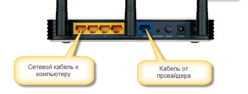
Рис. 2 – Места подключения кабелей
к содержанию ↑
Первичная наладка
Учитывая тот факт, что на данный момент модель не является самой свежей, она может попасть к вам в руки уже с некоторыми предварительными настройками.
Чаще всего они сделаны либо предыдущим пользователем, либо оператором/провайдером для оптимизации параметров работы, которые вряд ли соответствуют требуемым вам.
Соответственно, чтобы убрать эти негативные моменты, потребуется обнуление параметров устройства до заводских настроек.
Делается это достаточно просто. Маршрутизатор подключается к сети электропитания и после того, как загорится вся индикация, потребуется на задней части корпуса нажать кнопку RESET.
Ее потребуется несколько секунд удержать и после того, как все светодиодные индикаторы мигнут – отпустить.
Важно: производитель прячет кнопку внутри корпуса в целях безопасности. Поэтому чтобы ее нажать, потребуется особое приспособление вроде скрепки, которая входит в комплектацию некоторых смартфонов для замены SIM-карт.
Запуск WEB-интерфейса с помощью ПК
После того как установлена физическая связь компьютера с маршрутизатором, а роутер подключен к сети, можно приступать к настройке связи.
Для этого требуется запустить WEB-интерфейс, который обеспечит необходимое взаимодействие. Для его запуска понадобится любой браузер, к которому вы привыкли.
В адресной строке интернет-браузера следует набрать адрес, указанный на стикере, расположенном в донной части корпуса.
Обычно срабатывает комбинация символов 192.168.1.1, но производитель ее может изменить на буквенный эквивалент в зависимости от сборки. Поэтому стоит еще раз обратиться к данным на стикере.
Важно: не удаляйте стикер с корпуса, даже если вы уже настроили роутер. Данные, находящиеся на нем, могут понадобиться в будущем, когда по какой-либо причине настройки маршрутизатора будут сброшены до заводских.
После ввода адреса загрузится форма ввода, где потребуется указать логин с паролем в соответствующих ячейках.
Обычно в обе ячейки заносится слово admin, если на стикере производитель не указал иное. В результате данных действий будет загружен WEB-интерфейс настроек.
Если этого не произошло, проверьте соединение, сделанное с помощью патч-корда, и наличие электропитания.
А также на этом этапе можно проверить версию прошивки и при необходимости обновить ее. В противном случае все далее внесенные настройки будут потеряны при обновлении прошивки.
к содержанию ↑
Настройка подключения к Интернету
Без подключения к сети Интернет роутер будет способен обеспечить только локальную сеть.
Поэтому, чтобы обеспечить подключение устройства к глобальной сети, понадобится перейти в раздел меню «WAN».
Для этого требуется выбрать соответствующий раздел в горизонтальном меню, расположенном сверху.
Далее станет доступным меню, расположенное слева, в котором понадобится правильно выбрать технологию, которой провайдер обеспечивает соединение.
Эти данные следует уточнить именно у него, если они не указаны в договоре. Этот роутер дает возможность настраивать подключение по таким технологиям:
- Динамический IP;
- Статический IP;
- PPPoE;
- L2TP;
Этого набора достаточно для того, чтобы обеспечить подключение к сетям преимущественного большинства провайдеров.
Кроме того, из договора на подключение к интернету следует почерпнуть данные о том, использует ли ваш провайдер привязку по MAC-адресу.
Если это так, его следует клонировать, используя WEB-интерфейс.
Для этого следует перейти в подраздел Network.
В нем следует на пункте «WAN Connection Type» задать в списке соответствующую провайдеру технологию подключения, а после этого нажать кнопку «Клонировать».
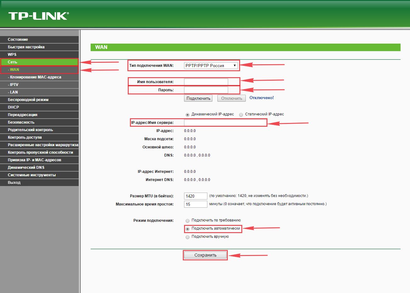
Рис. 3 – Раздел интерфейса «Сеть»
к содержанию ↑
Ваш провайдер использует динамический IP
Если провайдер использует технологию подключения «Динамический IP», достаточно выбрать в списке «Dynamic IP», чтобы появился доступ к глобальной сети.
Это можно проверить, открыв еще одну вкладку в браузере и запустив любимый сайт.
Если все работает, нужно вернуться на вкладку WEB-интерфейса и завершить настройку, нажав на кнопку «Save» (Сохранить).
Чтобы примененные параметры сохранились, требуется провести перезапуск устройства. Сделать это можно несколькими путями. Первый способ – использовать WEB-интерфейс.
Для этого требуется зайти в раздел «System Tools» и подраздел «Reboot», и нажать элемент Reboot (Перезагрузка).
После этого в разделе появится прогресс-бар, указывающий на выполнение перезагрузки.
Если такой вариант не устраивает, можно нажать на кнопку «ON», расположенную на задней части корпуса, чтобы произвести перезагрузку, или выключить и включить в сеть снова блок электропитания.
После этого можно переходить к активному использованию Интернета, а при необходимости еще и настроить раздачу другим пользователям и устройствам посредством Wi-Fi.
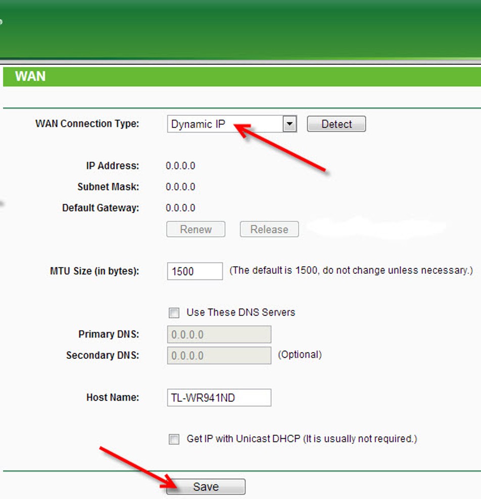
Рис. 4 – Настройка подключения по типу «Динамический IP»
к содержанию ↑
Статический IP в подключении
В том случае, если провайдер предоставляет вам возможность использования статического IP-адреса, преимущества использования которого известны большинству коммерческих организаций, список устанавливаемых настроек несколько расширяется.
Так, в разделе «WAN» (Сеть) независимо от технологии подключения требуется внести кроме стандартного имени пользователя, пароля и ip-адреса сервера еще дополнительные данные.
Чтобы поля для их ввода стали доступными, требуется необходимо установить маркер напротив элемента «Статический IP-адрес». В результате этого станут доступны для редактирования поля:
- «IP-адрес/Имя сервера»;
- «IP-адрес»;
- «Маска подсети»;
- «Основной шлюз»;
- «DNS».
Данные для них будут прописаны в договоре на оказание услуг связи провайдером.
Их после ввода потребуется зафиксировать, и чтобы это сделать, необходимо нажать элемент «Save» (Сохранить).
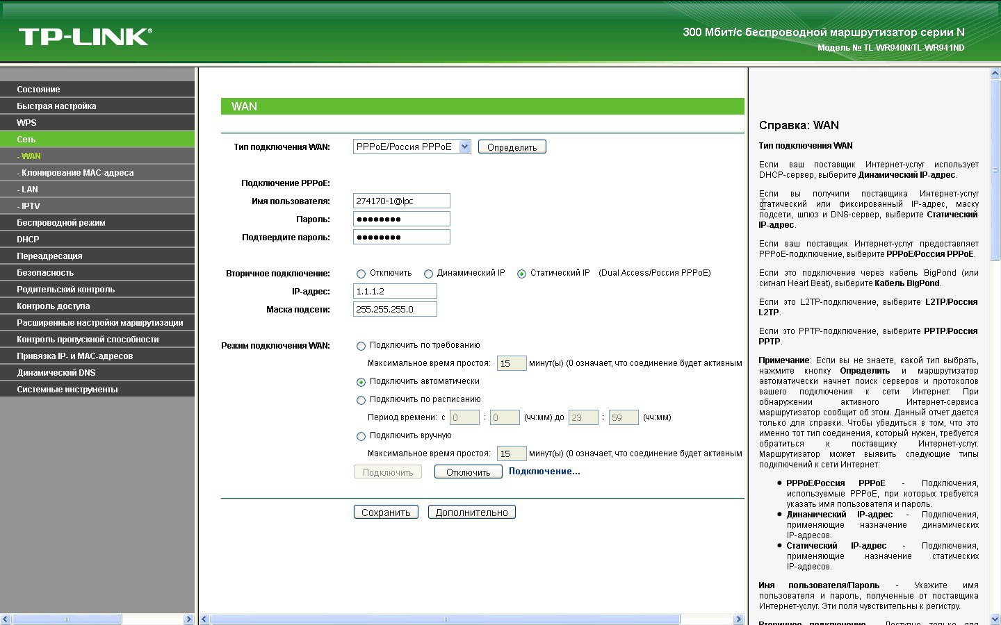
Рис. 5 – Подраздел «WAN», заполненный для PPPoE
к содержанию ↑
Параметры настройки Wi-Fi
Чтобы настроить параметры беспроводной связи, требуется перейти на раздел WEB-интерфейса «Wireless» (Беспроводная сеть). В нем нужно найти раздел «Wireless Settings».
Далее потребуется внести название сети, которое вам по душе, в поле SSID, а в соответствующем списке выбрать регион, чтобы обеспечить соответствующие региональные параметры беспроводной связи.
В подразделе «Wireless Security» в целях безопасности можно установить пароль, по которому будет открываться доступ к сети.
Для этого в пункте «WPA/WPA2» нужно выбрать значение «Personal», а в ячейке «Wireless Password» задать пароль. Право выбора пароля остается за вами.
Чтобы данные параметры беспроводной сети вступили в силу, нужно их обновить, нажав элемент «Save» (Сохранить).
Пароль можно будет позже удалить или заменить, при этом он может отличаться от того, который установлен на вход в WEB-интерфейс.
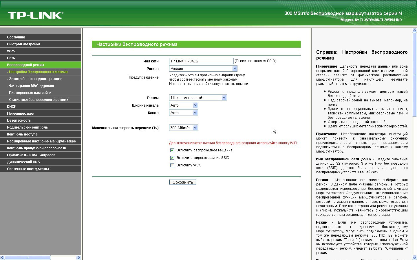
Рис. 6 – Подраздел «Настройки беспроводного режима»
к содержанию ↑
Региональные стандартные и прочие настройки
Чтобы избежать проблем с подключением к сети, стоит сразу настроить региональные стандарты. Это касается не только языка интерфейса, но и таких параметров, как дата и время.
Они связаны и с часовым поясом, который также требуется задавать вручную.
Все эти настройки устанавливаются в разделе «System Tools». Для этого используется подраздел «Time Settings».
Процедура эта проста и не занимает много времени, но по ее окончании важно не забыть сохранить параметры настройки, нажав элемент «Save» (Сохранить), иначе они так и не будут применены, а работа такого функционала, как, например, «Родительский контроль» будет нарушена.
В этом же разделе можно поменять стандартный пароль и логин доступа в WEB-интерфейс в целях защиты от взлома. Для этого служит специальный подраздел «Password».
В нем потребуется для смены указать в поле «Old User Name» и «Old Password» текущие логин и пароль, а в ячейках, указанных ниже – один раз новый логин и дважды пароль для подтверждения.
Совет: Чтобы новые данные для входа не потерялись, их стоит переписать или сохранить на другом устройстве.
При возникновении проблем с подключением можно дополнительно использовать специальный подраздел «Диагностика».
Он обеспечивает такие вспомогательные функции доступа к утилитам ping и traceroute, которые будут полезны в первую очередь представителям провайдера.
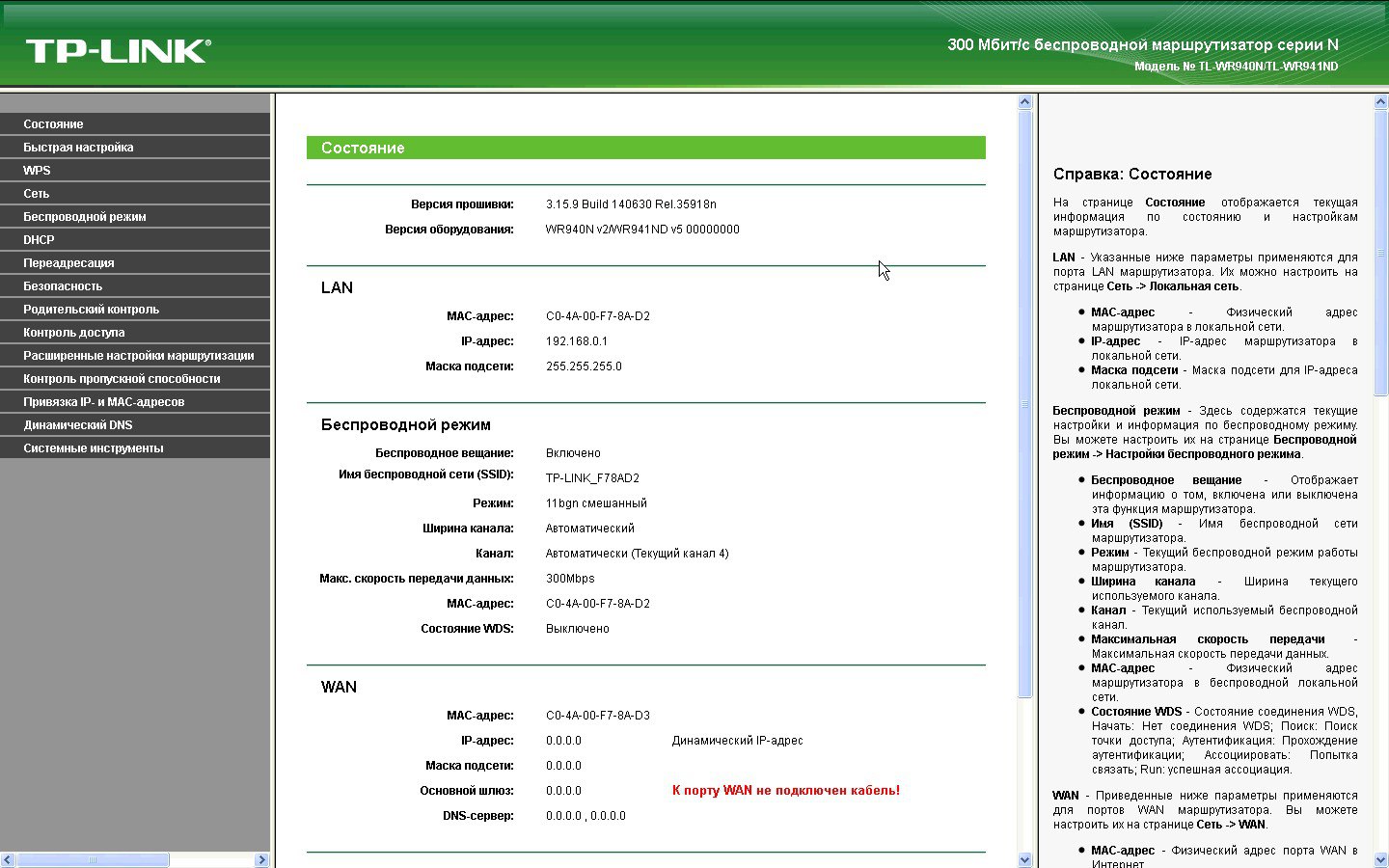
Рис. 7 – Базовая информация о настройках
к содержанию ↑
Мобильный клиент
Как уже отмечалось выше, для настройки могут использоваться не только стационарные, но и мобильные устройства. Для них имеется фирменное приложение, скачиваемое в Play Market или AppStore.
Оно позволяет не только настраивать сеть, используя подраздел «Управление», но и просматривать статистику.
К примеру, можно узнать:
- статус роутера;
- версию прошивки;
- количество трафика;
- количество и имена подключенных клиентов.
Здесь же можно заблокировать доступ нежелательных к подключению устройств.
Что касается раздела «Управление», он позволяет изменять такие параметры как:
- настройки подключения;
- беспроводные подключения;
- родительский контроль;
- системные и региональные настройки.
к содержанию ↑
Выводы и напутствие
Как видите, для модели TP Link TL WR940N настройка практически не отличается от процесса настройки других маршрутизаторов.
Доступно это благодаря простому унифицированному интерфейсу, который дополнен полноценной справочной системой, дающей подсказки к любой выполняемой операции.
При этом плюс в том, что прошивки имеют полностью русифицированную справку.
Стоит также отметить широкий функционал, который обеспечивает устройство. Выше была рассмотрена лишь основная часть настроек – именно тех, что будут полезны всем пользователям.
Но есть еще несколько функций, которые обеспечиваются не всеми провайдерами, к примеру, IPTV.
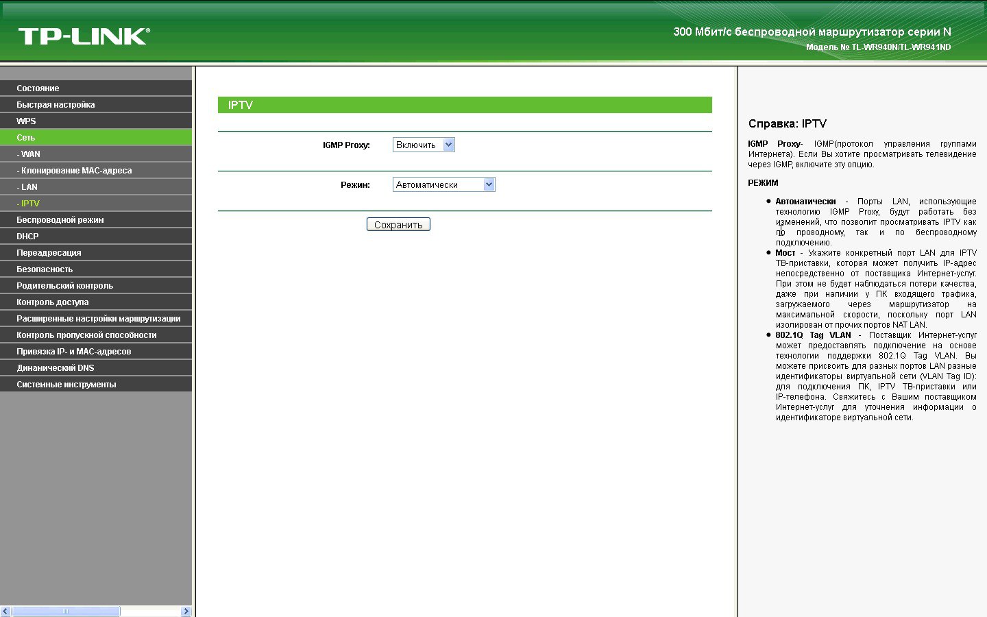
Рис. 8 – Подраздел «IPTV» с подсказками

1910011859 REV4.0.0
TL-WR940N
User Guide
450Mbps Wireless N Router

Contents
About This Guide …………………………………………………………………………………..1
Chapter 1. Get to Know About Your Router . . . . . . . . . . . . . . . . . . . . . . . . . 2
1. 1. Product Overview . . . . . . . . . . . . . . . . . . . . . . . . . . . . . . . . . . . . . . . . . . . . . . . . . . . . . . . . . . 3
1. 2. Panel Layout . . . . . . . . . . . . . . . . . . . . . . . . . . . . . . . . . . . . . . . . . . . . . . . . . . . . . . . . . . . . . . . 3
Chapter 2. Connect the Hardware. . . . . . . . . . . . . . . . . . . . . . . . . . . . . . . . . . 6
2. 1. Position Your Router. . . . . . . . . . . . . . . . . . . . . . . . . . . . . . . . . . . . . . . . . . . . . . . . . . . . . . . . 7
2. 2. Connect Your Router . . . . . . . . . . . . . . . . . . . . . . . . . . . . . . . . . . . . . . . . . . . . . . . . . . . . . . . 7
Chapter 3. Set Up Internet Connection Via Quick Setup Wizard . . . . . 10
3. 1. Log into the Router. . . . . . . . . . . . . . . . . . . . . . . . . . . . . . . . . . . . . . . . . . . . . . . . . . . . . . . . 11
3. 2. Configure the Router . . . . . . . . . . . . . . . . . . . . . . . . . . . . . . . . . . . . . . . . . . . . . . . . . . . . . . 11
Chapter 4. Configure . . . . . . . . . . . . . . . . . . . . . . . . . . . . . . . . . . . . . . . . . . . . . 14
4. 1. Status. . . . . . . . . . . . . . . . . . . . . . . . . . . . . . . . . . . . . . . . . . . . . . . . . . . . . . . . . . . . . . . . . . . . . 15
4. 2. WPS . . . . . . . . . . . . . . . . . . . . . . . . . . . . . . . . . . . . . . . . . . . . . . . . . . . . . . . . . . . . . . . . . . . . . . 16
4. 3. Network . . . . . . . . . . . . . . . . . . . . . . . . . . . . . . . . . . . . . . . . . . . . . . . . . . . . . . . . . . . . . . . . . . 18
4. 4. Wireless. . . . . . . . . . . . . . . . . . . . . . . . . . . . . . . . . . . . . . . . . . . . . . . . . . . . . . . . . . . . . . . . . . . 26
4. 5. DHCP . . . . . . . . . . . . . . . . . . . . . . . . . . . . . . . . . . . . . . . . . . . . . . . . . . . . . . . . . . . . . . . . . . . . . 33
4. 6. Forwarding . . . . . . . . . . . . . . . . . . . . . . . . . . . . . . . . . . . . . . . . . . . . . . . . . . . . . . . . . . . . . . . 35
4. 7. Security . . . . . . . . . . . . . . . . . . . . . . . . . . . . . . . . . . . . . . . . . . . . . . . . . . . . . . . . . . . . . . . . . . . 39
4. 8. Parental Controls . . . . . . . . . . . . . . . . . . . . . . . . . . . . . . . . . . . . . . . . . . . . . . . . . . . . . . . . . . 44
4. 9. Access Control . . . . . . . . . . . . . . . . . . . . . . . . . . . . . . . . . . . . . . . . . . . . . . . . . . . . . . . . . . . . 46
4. 10. Advanced Routing . . . . . . . . . . . . . . . . . . . . . . . . . . . . . . . . . . . . . . . . . . . . . . . . . . . . . . . . 48
4. 11. Bandwidth Control . . . . . . . . . . . . . . . . . . . . . . . . . . . . . . . . . . . . . . . . . . . . . . . . . . . . . . . . 50
4. 12. IP&MAC Binding. . . . . . . . . . . . . . . . . . . . . . . . . . . . . . . . . . . . . . . . . . . . . . . . . . . . . . . . . . . 52
4. 13. Dynamic DNS . . . . . . . . . . . . . . . . . . . . . . . . . . . . . . . . . . . . . . . . . . . . . . . . . . . . . . . . . . . . . 54
4. 14. IPv6 Support . . . . . . . . . . . . . . . . . . . . . . . . . . . . . . . . . . . . . . . . . . . . . . . . . . . . . . . . . . . . . . 56
4. 15. System Tools . . . . . . . . . . . . . . . . . . . . . . . . . . . . . . . . . . . . . . . . . . . . . . . . . . . . . . . . . . . . . . 63
4. 16. Logout. . . . . . . . . . . . . . . . . . . . . . . . . . . . . . . . . . . . . . . . . . . . . . . . . . . . . . . . . . . . . . . . . . . . 71
FAQ ………………………………………………………………………………………………………72
1
About This Guide
This guide is a complementation of Quick Installation Guide. The Quick Installation
Guide instructs you on quick Internet setup, and this guide provides details of each
function and shows you the way to configure these functions appropriate to your
needs.
When using this guide, please notice that features of the router may vary slightly
depending on the model and software version you have, and on your location, language,
and Internet service provider. All screenshots, images, parameters and descriptions
documented in this guide are used for demonstration only.
Conventions
In this guide the following conventions are used:
Convention Description
Blue Italic Hyperlinks are in blue italic. You can click to redirect to a website or a specific section.
Blue Contents to be emphasized and texts on the web page are in blue, including the
menus, items, buttons, etc.
>
The menu structures to show the path to load the corresponding page. For example,
Advanced > Wireless > MAC Filtering means the MAC Filtering function page is under
the Wireless menu that is located in the Advanced tab.
Note: Ignoring this type of note might result in a malfunction or damage to the device.
Tips: Indicates important information that helps you make better use of your device.
More Info
The latest software, management app and utility can be found at Download Center at
www.tp-link.com/support.
The Quick Installation Guide can be found where you find this guide or inside the
package of the router.
Specifications can be found on the product page at http://www.tp-link.com.
A Technical Support Forum is provided for you to discuss our products at
http://forum.tp-link.com.
Our Technical Support contact information can be found at the Contact Technical
Support page at www.tp-link.com/support.

Chapter 1
Get to Know About Your
Router
This chapter introduces what the router can do and shows its appearance.
This chapter contains the following sections:
• Product Overview
• Panel Layout

3
Chapter 1 Get to Know About Your Router
1. 1. Product Overview
The TP-LINK router is designed to fully meet the need of Small Office/Home Office
(SOHO) networks and users demanding higher networking performance. The powerful
antennas ensure continuous Wi-Fi signal to all your devices while boosting widespread
coverage throughout your home, and the built-in Ethernet ports supply high-speed
connection to your wired devices.
Moreover, it is simple and convenient to set up and use the TP-LINK router due to its
intuitive web interface and the powerful Tether app.
1. 2. Panel Layout
1. 2. 1. Top View
The router’s LEDs (view from left to right) are located on the front panel. You can check
the router’s working status by following the LED Explanation table.
LED Explanation
Name Status Indication
(Power)
On System initialization completes.
Flashing System initialization or firmware upgrade is in process. Do not
disconnect or power off the router.
Off Power is off.

4
Chapter 1 Get to Know About Your Router
LED Explanation
Name Status Indication
(Wireless)
On The wireless function is working properly.
Off The wireless function is disabled.
(Ethernet)
On At least one Ethernet port is connected.
Off No Ethernet port is connected.
(Internet)
Blue On The Internet is available.
Orange On The router’s Internet port is connected, but the Internet
is not available.
Off The router’s Internet port is not connected.
(WPS)
On/Off Turns on when WPS connection is established, and goes off about 5
minutes later.
Flashing A wireless device is trying to connect to the network via WPS. This
process may take up to 2 minutes.
1. 2. 2. The Back Panel
The following parts (view from left to right) are located on the rear panel.
Item Description
Power Port For connecting the router to a power socket via the provided power
adapter.
Power On/Off Button Press this button to power on or off the router.
Reset Button Use a pin to press and hold this button until all the LED turn on momentarily
to reset the router to its factory default settings.

5
Chapter 1 Get to Know About Your Router
Item Description
WPS/Wi-Fi Button
Press and hold this button until the LED is on/off to turn on/off the Wi-Fi
function.
To enable the WPS function, press this button about 2 seconds. If you have
a WPS-supported device, you can press this button to quickly establish
connection between the router and the client device and automatically
configure wireless security for your wireless network.
Internet Port For connecting to a DSL/Cable modem, or an Ethernet port.
Ethernet Ports (1/2/3/4) For connecting your PCs or other wired network devices to the router.
Antennas Used for wireless operation and data transmitting. Upright them for the
best Wi-Fi performance.

Chapter 2
Connect the Hardware
This chapter contains the following sections:
• Position Your Router
• Connect Your Router

7
Chapter 2 Connect the Hardware
2. 1. Position Your Router
• The product should not be located where it will be exposed to moisture or excessive
heat.
• Place the router in a location where it can be connected to the various devices as well
as to a power source.
• Make sure the cables and power cord are safely placed out of the way so they do not
create a tripping hazard.
• The router can be placed on a shelf or desktop.
• Keep the router away from strong electromagnetic radiation and devices of
electromagnetic sensitive.
2. 2. Connect Your Router
1. Follow the steps below to connect your router.
If your Internet connection is through an Ethernet cable from the wall instead of
through a DSL / Cable / Satellite modem, connect the Ethernet cable directly to the
router’s Internet port, then follow Step 4 and 5 to complete the hardware connection.
Internet
1
3
2
Router
Modem
Power adapter
Power adapter 4
1 ) Turn off the modem, and remove the backup battery if it has one.
2 ) Connect the modem to the Internet port on your router with an Ethernet cable.
3 ) Turn on the modem, and then wait about 2 minutes for it to restart.
4 ) Turn on the router.

8
Chapter 2 Connect the Hardware
5 ) Verify that the hardware connection is correct by checking these LEDs.
On
Internet
Power
On
Wireless
On
Tips: If wireless LED is off, press and hold the WPS/Wi-Fi button until it is on.
2. Connect your computer to the router.
• Method 1: Wired
Turn off the Wi-Fi on your computer and connect the devices as shown below.
Ethernet cable
• Method 2: Wirelessly
1 ) Find the SSID (Network Name) and Wireless Password printed on the label at
the bottom of the router.
2 ) Click the network icon of your computer or go to Wi-Fi Setting of your smart
device, and then select the SSID to join the network.
or
Connections are available
Wireless Network Connection
Connect automatically Connect
√
TP-LINK_XXXX
TP-LINK_123456
Wi-Fi
Wi-Fi
TP-LINK_XXXX
TP-LINK_123456
CHOOSE A NETWORK…
Other…
< Settings
Smart DeviceComputer
• Method 3: Use the WPS button
Wireless devices that support WPS, including Android phones, tablets, most USB
network cards, can be connected to your router through this method. (WPS is not
supported by iOS devices).
Note:
The WPS function cannot be configured if the wireless function of the router is disabled. Also, the WPS function will
be disabled if your wireless encryption is WEP. Please make sure the wireless function is enabled and is configured
with the appropriate encryption before configuring the WPS.
1. Tab the WPS icon on the device’s screen.
2. Immediately press the WPS button on your router.

9
Chapter 2 Connect the Hardware
Close to

Chapter 3
Set Up Internet Connection
Via Quick Setup Wizard
This chapter introduces how to connect your router to the Internet via the web-based
Quick Setup Wizard.
This chapter contains the following sections:
• Log into the Router
• Configure the Router

11
Chapter 3 Set Up Internet Connection Via Quick Setup Wizard
3. 1. Log into the Router
With the web-based utility, it is easy to configure and manage the router. The web-
based utility can be used on any Windows, Macintosh or UNIX OS with a Web browser,
such as Microsoft the Internet Explorer, Mozilla Firefox or Apple Safari.
Follow the steps below to log into your router.
1. Set up the TCP/IP Protocol in Obtain an IP address automatically mode on your
computer.
2. Visit http://tplinkwifi.net, and log in with the username and password you set for the
router. The default one is admin (all lowercase) for both username and password.
Note:
If the login window does not appear, please refer to the FAQ section.
3. 2. Configure the Router
The Quick Setup Wizard will guide you through the process to set up your router.
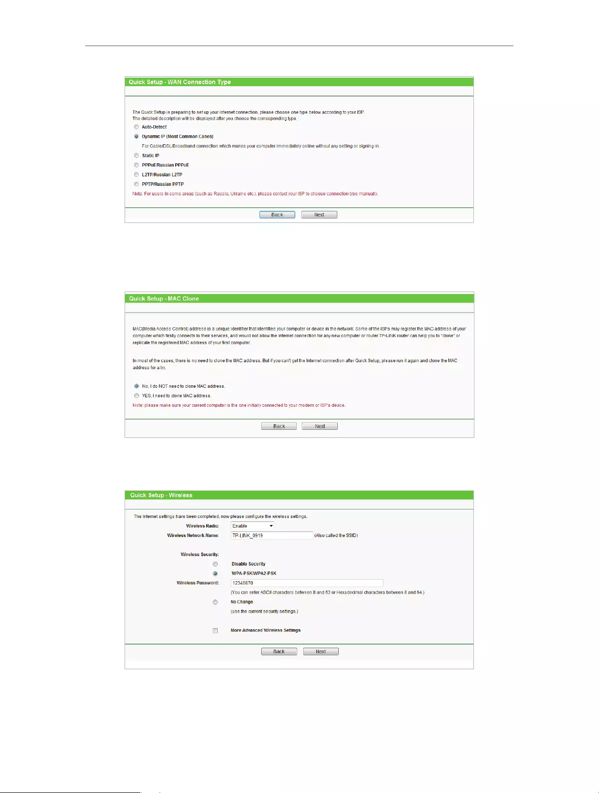
1. Go to Quick Setup and click Next to start.
2. Click Auto Detect and the router will detect your connection type automatically.
Note:
• You can also choose the connection type manually. Contact your ISP if you are not sure about the Internet
connection information.
• If you use DSL line and you are only provided with an account name and a password by your ISP, choose PPPoE.
• If you use cable TV or fiber cable, choose Dynamic IP.
• If you are provided with more information such as IP address, Subnet Mask and Default Gateway, choose Static IP.
12
Chapter 3 Set Up Internet Connection Via Quick Setup Wizard
3. In this case, we take dynamic IP for instance. Please select to clone the mac address
or not and click Next. For other connection types, please enter the parameters
provided by your ISP, and then click Next.
4. Either customize your Wireless Network Name and Wireless Password or keep the
default ones , and then click Next.
5. Click Finish to complete the configuration. Now your computers and Wi-Fi devices
can connect to the Internet!

13
Chapter 3 Set Up Internet Connection Via Quick Setup Wizard

Chapter 4
Configure
This chapter presents how to configure the various features of the router.
This chapter contains the following sections:
• Status
• WPS
• Network
• Wireless
• DHCP
• Forwarding
• Security
• Parental Controls
• Access Control
• Advanced Routing
• Bandwidth Control
• IP&MAC Binding
• Dynamic DNS
• IPv6 Support
• System Tools
• Logout
15
Chapter 4 Congure
4. 1. Status
1. Visit http://tplinkwifi.net, and log in with the username and password you set for
the router.
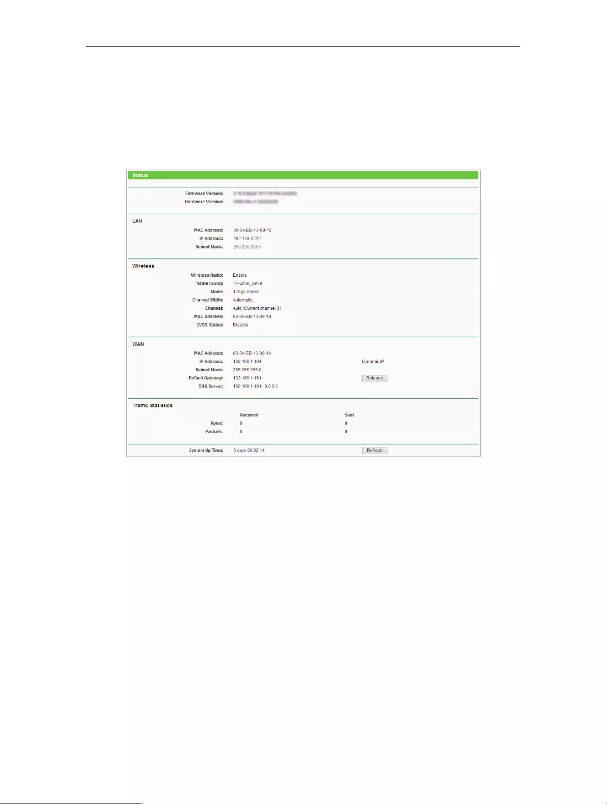
2. Go to Status. You can view the current status information of the router.
• Firmware Version — The version information of the router’s firmware.
• Hardware Version — The version information of the router’s hardware.
• LAN — This field displays the current settings of the LAN, and you can configure them
on the Network > LAN page.
• MAC address — The physical address of the router.
• IP address — The LAN IP address of the router.
• Subnet Mask — The subnet mask associated with the LAN IP address.
• Wireless — This field displays the basic information or status of the wireless function,
and you can configure them on the Wireless > Wireless Settings page.
• Wireless Radio — Indicates whether the wireless feature is enabled or not.
• Name (SSID) — The SSID of the router.
• Mode — The current wireless working mode in use.
• Channel Width — The current wireless channel width in use.
• Channel — The current wireless channel in use.

16
Chapter 4 Congure
• MAC Address — The physical address of the router.
• WDS Status — The status of WDS connection.
• WAN — This field displays the current settings of the WAN, and you can configure them
on the Network > WAN page.
• MAC Address — The physical address of the WAN port.
• IP Address — The current WAN (Internet) IP Address. This field will be blank
or 0.0.0.0 if the IP Address is assigned dynamically and there is no Internet
connection.
• Subnet Mask — The subnet mask associated with the WAN IP Address.
• Default Gateway — The Gateway currently used is shown here. When you use
Dynamic IP as the Internet connection type, click Renew or Release here to
obtain new IP parameters dynamically from the ISP or release them.
• DNS Server — The IP addresses of DNS (Domain Name System) server.
• Traffic Statistics — The router’s traffic statistics.
• Received (Bytes) — Traffic in bytes received from the WAN port.
• Received (Packets) — Traffic in packets received from the WAN port.
• Sent (Bytes) — Traffic in bytes sent out from the WAN port.
• Sent (Packets) — Traffic in packets sent out from the WAN port.
• System Up Time — The length of the time since the router was last powered on or reset.
Click Refresh to get the latest status and settings of the router.
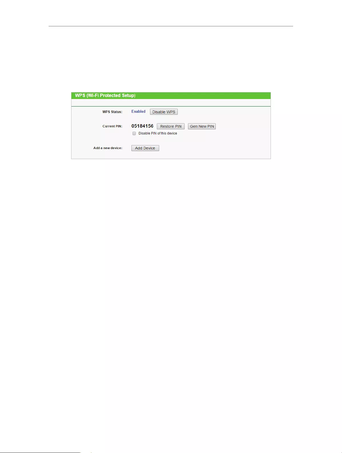
4. 2. WPS
WPS (Wi-Fi Protected Setup) can help you to quickly and securely connect to a network.
This section will guide you to add a new wireless device to your router’s network quickly
via WPS.
Note:
The WPS function cannot be configured if the wireless function of the router is disabled. Please make sure the
wireless function is enabled before configuration.
1. Visit http://tplinkwifi.net, and log in with the username and password you set for
the router.
2. Go to WPS.
3. Follow one of the following three methods to connect your client device to the
router’s Wi-Fi network.
Method ONE: Press the WPS Button on Your Client Device
1. Keep the WPS Status as Enabled and click Add Device.

17
Chapter 4 Congure
2. Select Press the button of the new device in two minutes and click Connect.
3. Within two minutes, press the WPS button on your client device.
4. A success message will appear on the WPS page if the client device has been
successfully added to the router’s network.
Method TWO: Enter the Client’s PIN
1. Keep the WPS Status as Enabled and click Add Device.
2. Select Enter the new device’s PIN, enter your client device’s current PIN in the PIN
filed and click Connect.
18
Chapter 4 Congure
3. A success message will appear on the WPS page if the client device has been
successfully added to the router’s network.
Method Three: Enter the Router’s PIN
1. Keep the WPS Status as Enabled and get the Current PIN of the router.
2. Enter the router’s current PIN on your client device to join the router’s Wi-Fi network.
4. 3. Network
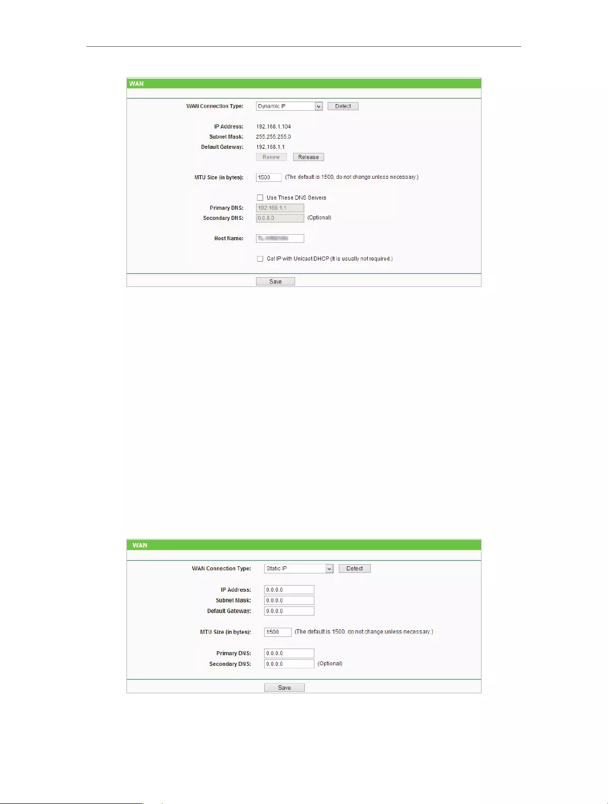
4. 3. 1. WAN
1. Visit http://tplinkwifi.net, and log in with the username and password you set for
the router.
2. Go to Network > WAN.
3. Configure the IP parameters of the LAN and click Save.
Dynamic IP
If your ISP provides the DHCP service, please select Dynamic IP, and the router will
automatically get IP parameters from your ISP.
Click Renew to renew the IP parameters from your ISP.
Click Release to release the IP parameters.
19
Chapter 4 Congure
• MTU Size — The normal MTU (Maximum Transmission Unit) value for most Ethernet
networks is 1500 Bytes. It is not recommended that you change the default MTU Size
unless required by your ISP.
• Use These DNS Servers — If your ISP providess you one or two DNS addresses, select
Use These DNS Servers and enter the primary and secondary addresses. Otherwise,
the DNS servers will be assigned dynamically from your ISP.
• Host Name — This option specifies the name of the router.
• Get IP with Unicast DHCP — A few ISPs’ DHCP servers do not support the broadcast
applications. If you cannot get the IP address normally, you can choose this option. (It
is rarely required.)
Static IP
If your ISP provides a static or fixed IP address, subnet mask, default gateway and DNS
setting, please select Static IP.
• IP Address — Enter the IP address in dotted-decimal notation provided by your ISP.
20
Chapter 4 Congure
• Subnet Mask — Enter the subnet mask in dotted-decimal notation provided by your
ISP. Normally 255.255.255.0 is used as the subnet mask..
• Default Gateway — Enter the gateway IP address in dotted-decimal notation provided
by your ISP.
• MTU Size — The normal MTU (Maximum Transmission Unit) value for most Ethernet
networks is 1500 Bytes. It is not recommended that you change the default MTU size
unless required by your ISP.
• Primary/Secondary DNS — (Optional) Enter one or two DNS addresses in dotted-
decimal notation provided by your ISP.
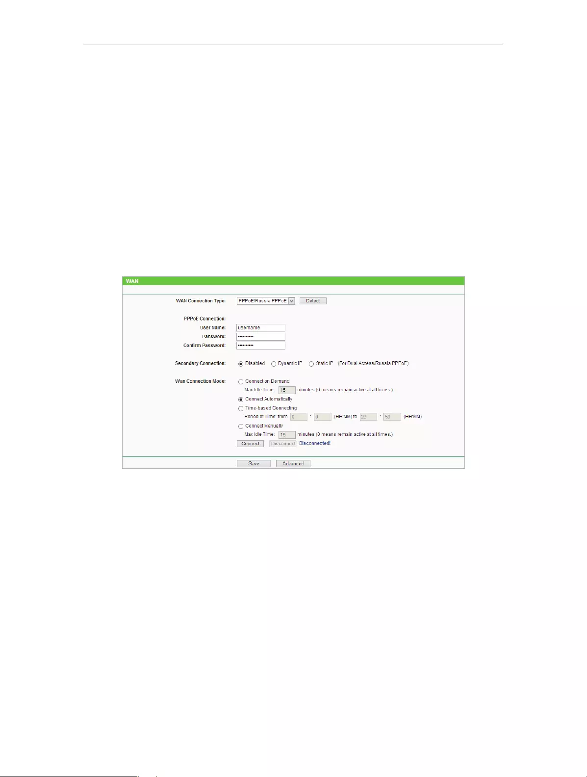
PPPoE/Russia PPPoE
If your ISP provides PPPoE connection, select PPPoE/Russia PPPoE.
• User Name/Password — Enter the user name and password provided by your ISP. These
fields are case-sensitive.
• Confirm Password — Enter the Password provided by your ISP again to ensure the
password you entered is correct.
• Secondary Connection — It’s available only for PPPoE connection. If your ISP provides
an extra connection type, select Dynamic IP or Static IP to activate the secondary
connection.
• WAN Connection Mode
• Connect on Demand — In this mode, the Internet connection can be terminated
automatically after a specified inactivity period (Max Idle Time) and be re—
established when you attempt to access the Internet again. If you want to keep
your Internet connection active all the time, please enter 0 in the Max Idle Time
field. Otherwise, enter the number of minutes you want to have elapsed before
your Internet access disconnects.

21
Chapter 4 Congure
• Connect Automatically — The connection can be re-established automatically
when it is down.
• Time-based Connecting — The connection will only be established in the period
from the start time to the end time (both are in HH:MM format).
• Connect Manually — You can click Connect/Disconnect to connect/disconnect
immediately. This mode also supports the Max Idle Time function as Connect
on Demand mode. The Internet connection can be disconnected automatically
after a specified inactivity period (Max Idle Time) and not be able to re-establish
when you attempt to access the Internet again.
Note:
• Only when you have configured the system time on the System Tools > Time Settings page, will the time-based
connecting function take effect.
• Sometimes the connection cannot be terminated although you have specified the Max Idle Time because some
applications are visiting the Internet continually in the background.
If you want to do some advanced configurations, please click Advanced.
• MTU Size — The default MTU size is 1480 bytes. It is not recommended that you change
the default MTU size unless required by your ISP.
• Service Name/AC Name — The service name and AC (Access Concentrator) name
should not be configured unless you are sure it is necessary for your ISP. In most cases,
leaving these fields blank will work.
• ISP Specified IP Address — If your ISP does not automatically assign IP addresses to the
router, please select Use IP address specified by ISP and enter the IP address provided
by your ISP in dotted-decimal notation.
• Detect Online Interval — The router will detect Access Concentrator online at every
interval. The default value is 0. You can input the value between 0 and 120. The value
0 means no detect.
• Primary DNS/Secondary DNS — If your ISP does not automatically assign DNS addresses
to the router, please select Use the following DNS servers and enter the IP address in

22
Chapter 4 Congure
dotted-decimal notation of your ISP’s primary DNS server. If a secondary DNS server
address is available, enter it as well.
BigPond Cable
If your ISP provides BigPond cable connection, please select BigPond Cable.
• User Name/Password — Enter the user name and password provided by your ISP. These
fields are case-sensitive.
• Auth Server — Enter the authenticating server IP address or host name.
• Auth Domain — Type in the domain suffix server name based on your location.
• MTU Size — The default MTU size is 1480 bytes. It is not recommended that you change
the default MTU Size unless required by your ISP.
• Connection Mode
• Connect on Demand — In this mode, the Internet connection can be terminated
automatically after a specified inactivity period (Max Idle Time) and be re—
established when you attempt to access the Internet again. If you want to keep
your Internet connection active all the time, please enter 0 in the Max Idle Time
field. Otherwise, enter the number of minutes you want to have elapsed before
your Internet access disconnects.
• Connect Automatically — The connection can be re-established automatically
when it is down.
• Connect Manually — You can click Connect/Disconnect to connect/disconnect
immediately. This mode also supports the Max Idle Time function as Connect
on Demand mode. The Internet connection can be disconnected automatically
after a specified inactivity period (Max Idle Time) and not be able to re-establish
when you attempt to access the Internet again.
23
Chapter 4 Congure
Note:
Sometimes the connection cannot be terminated although you have specified the Max Idle Time because some
applications are visiting the Internet continually in the background.
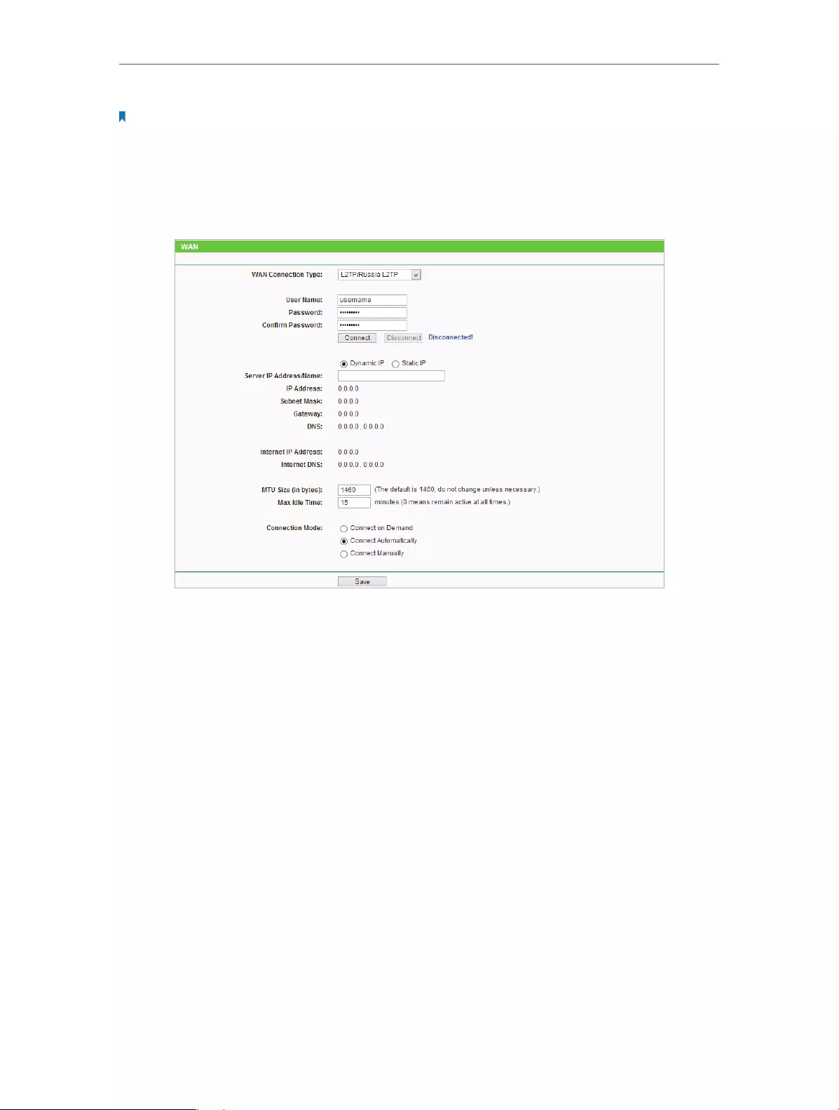
L2TP/Russia L2TP
If your ISP provides L2TP connection, please select L2TP/Russia L2TP.
• User Name/Password — Enter the user name and password provided by your ISP. These
fields are case-sensitive.
• Confirm Password — Enter the Password provided by your ISP again to ensure the
password you entered is correct.
• Connect/Disconnect — Click this button to connect or disconnect immediately.
• Dynamic IP/ Static IP — Select either as required by your ISP. If Static IP is selected,
please enter the IP address, subnet marsk, gateway and DNS also provided by your
ISP.
• Internet IP Address/ Internet DNS — The Internet IP address and DNS server address
assigned by L2TP server.
• Connection Mode
• Connect on Demand — In this mode, the Internet connection can be terminated
automatically after a specified inactivity period (Max Idle Time) and be re—
established when you attempt to access the Internet again. If you want to keep
your Internet connection active all the time, please enter 0 in the Max Idle Time
field. Otherwise, enter the number of minutes you want to have elapsed before
your Internet access disconnects.

24
Chapter 4 Congure
• Connect Automatically — The connection can be re-established automatically
when it is down.
• Connect Manually — You can click Connect/Disconnect to connect/disconnect
immediately. This mode also supports the Max Idle Time function as Connect
on Demand mode. The Internet connection can be disconnected automatically
after a specified inactivity period (Max Idle Time) and not be able to re-establish
when you attempt to access the Internet again.
Note:
Sometimes the connection cannot be terminated although you have specified the Max Idle Time because some
applications are visiting the Internet continually in the background.
PPTP/Russia PPTP
If your ISP provides PPTP connection, please select PPTP/Russia PPTP.
• User Name/Password — Enter the user name and password provided by your ISP. These
fields are case-sensitive.
• Confirm Password — Enter the Password provided by your ISP again to ensure the
password you entered is correct.
• Connect/Disconnect — Click this button to connect or disconnect immediately.
• Dynamic IP/ Static IP — Select either as required by your ISP. If Static IP is selected,
please enter the IP address, subnet marsk, gateway and DNS also provided by your
ISP.
• Internet IP Address/ Internet DNS — The Internet IP address and DNS server address
assigned by L2TP server.

25
Chapter 4 Congure
• Connection Mode
• Connect on Demand — In this mode, the Internet connection can be terminated
automatically after a specified inactivity period (Max Idle Time) and be re—
established when you attempt to access the Internet again. If you want to keep
your Internet connection active all the time, please enter 0 in the Max Idle Time
field. Otherwise, enter the number of minutes you want to have elapsed before
your Internet access disconnects.
• Connect Automatically — The connection can be re-established automatically
when it is down.
• Connect Manually — You can click Connect/Disconnect to connect/disconnect
immediately. This mode also supports the Max Idle Time function as Connect
on Demand mode. The Internet connection can be disconnected automatically
after a specified inactivity period (Max Idle Time) and not be able to re-establish
when you attempt to access the Internet again.
Note:
Sometimes the connection cannot be terminated although you have specified the Max Idle Time because some
applications are visiting the Internet continually in the background.
4. 3. 2. MAC Clone
1. Visit http://tplinkwifi.net, and log in with the username and password you set for
the router.
2. Go to Network > MAC Clone.
3. Configure the WAN MAC address and click Save.
• WAN MAC Address — This field displays the current MAC address of the WAN port.
If your ISP requires you to register the MAC address, please enter the correct MAC
address in this field. Click Restore Factory MAC to restore the MAC address of WAN
port to the factory default value.
• Your PC’s MAC Address — This field displays the MAC address of the PC that is managing
the router. If the MAC address is required, you can click Clone MAC Address and this
MAC address will be filled in the WAN MAC Address field.
Note:
• You can only use the MAC Address Clone function for PCs on the LAN.
• If you have changed the WAN MAC address when the WAN connection is PPPoE, it will not take effect until the
connection is re-established.

26
Chapter 4 Congure
4. 3. 3. LAN
1. Visit http://tplinkwifi.net, and log in with the username and password you set for
the router.
2. Go to Network > LAN.
3. Configure the IP parameters of the LAN and click Save.
• MAC Address — The physical address of the LAN ports. The value can not be changed.
• IP Address — Enter the IP address in dotted-decimal notation of your router (factory
default — 192.168.0.254).
• Subnet Mask — An address code that determines the size of the network. Normally
255.255.255.0 is used as the subnet mask.
• IGMP Proxy — The Internet Group Management Protocol (IGMP) feature allow you to
watch TV on IPTV-supported devices in the LAN .
Note:
• If you have changed the IP address, you must use the new IP address to login.
• If the new IP address you set is not in the same subnet as the old one, the IP address pool in the DHCP Server will
be configured automatically, but the Virtual Server and DMZ Host will not take effect until they are re-configured.
4. 4. Wireless
4. 4. 1. Wireless Settings
1. Visit http://tplinkwifi.net, and log in with the username and password you set for
the router.
2. Go to Wireless > Wireless Settings.
3. Configure the basic settings for the wireless network and click Save.

27
Chapter 4 Congure
• Wireless Network Name — Enter a string of up to 32 characters. The default SSID is
TP-LINK_XXXX (XXXX indicates the last unique four numbers of each Router’s MAC
address). It is strongly recommended that you change your network name (SSID). This
value is case-sensitive. For example, TEST is NOT the same as test.
• Mode — Select the desired mode. It is strongly recommended that you keep the
default setting 11bgn mixed, so that all 802.11b/g/n wireless devices can connect to
the router.
Note:
If 11bg mixed mode is selected, the Channel Width field will turn grey and the value will become 20M, and cannot
be changed.
• Channel Width — Select any channel width from the drop-down list. The default setting
is Auto, which can automatically adjust the channel width for your clients.
• Channel — This field determines which operating frequency will be used. The default
channel is set to Auto. It is not necessary to change the wireless channel unless you
notice interference problems with another nearby access point.
• Enable Wireless Router Radio — The wireless radio of the router can be enabled or
disabled to allow or deny wireless access. If enabled, the wireless clients will be able
to access the router.
• Enable SSID Broadcast — If enabled, the router will broadcast the wireless network
name (SSID).
• Enable WDS Bridging — You can select this to enable WDS Bridging, with this function,
the Router can bridge two or more WLANs.
Note:
If this checkbox is selected, you had better make sure the following settings are correct.

28
Chapter 4 Congure
• SSID (to be bridged) — The SSID of the AP your Router is going to connect to as a client.
You can also use the survey function to select the SSID to join.
• BSSID (to be bridged) — The BSSID of the AP your Router is going to connect to as a
client. You can also use the survey function to select the BSSID to join.
• Survey — Click this button, you can search the AP which runs in the current channel.
• WDS Mode — This field determines which WDS Mode will be used. It is not necessary
to change the WDS Mode unless you notice network communication problems
with root AP. If you select Auto, then Router will choose the appropriate WDS Mode
automatically.
• Key type — This option should be chosen according to the AP’s security configuration.
It is recommended that the security type is the same as your AP’s security type
• WEP Index — This option should be chosen if the key type is WEP (ASCII) or WEP (HEX).
It indicates the index of the WEP key.
• Auth Type — This option should be chosen if the key type is WEP (ASCII) or WEP (HEX).
It indicates the authorization type of the Root AP.
• Password — If the AP your Router is going to connect needs password, you need to fill
the password in this blank.
4. 4. 2. Wireless Security
1. Visit http://tplinkwifi.net, and log in with the username and password you set for
the router.
2. Go to Wireless > Wireless Security.
3. Configure the the security settings of your wireless network and click Save.

29
Chapter 4 Congure
• Disable Security — The wireless security function can be enabled or disabled. If
disabled, wireless clients can connect to the router without a password. It’s strongly
recommended to choose one of the following modes to enable security.
• WPA-PSK/WPA2-Personal — It’s the WPA/WPA2 authentication type based on pre-
shared passphrase.
• Version — Select Automatic, WPA-PSK or WPA2-PSK.
• Encryption — Select Automatic, TKIP or AES.
• Wireless Password — Enter ASCII or Hexadecimal characters. For Hexadecimal,
the length should be between 8 and 64 characters; for ASCII, the length should
be between 8 and 63 characters.
• Group Key Update Period — Specify the group key update interval in seconds.
The value can be 0 or at least 30. Enter 0 to disable the update.
• WPA /WPA2-Enterprise — It’s based on Radius Server.
• Version — Select Automatic, WPA or WPA2.
• Encryption — Select Automatic, TKIP or AES.
• Radius Server IP — Enter the IP address of the Radius server.
• Radius Port — Enter the port that Radius server used.
• Radius Password — Enter the password for the Radius server.
• Group Key Update Period — Specify the group key update interval in seconds.
The value should be 30 or above. Enter 0 to disable the update.
• WEP — It is based on the IEEE 802.11 standard.

30
Chapter 4 Congure
• Type — The default setting is Automatic, which can select Shared Key or Open
System authentication type automatically based on the wireless client’s
capability and request.
• WEP Key Format — Hexadecimal and ASCII formats are provided here.
Hexadecimal format stands for any combination of hexadecimal digits (0-9,
a-f, A-F) in the specified length. ASCII format stands for any combination of
keyboard characters in the specified length.
• WEP Key (Password) — Select which of the four keys will be used and enter the
matching WEP key. Make sure these values are identical on all wireless clients
in your network.
• Key Type — Select the WEP key length (64-bit, 128-bit or 152-bit) for encryption.
Disabled means this WEP key entry is invalid.
• 64-bit — Enter 10 hexadecimal digits (any combination of 0-9, a-f and A-F. Null
key is not permitted) or 5 ASCII characters.
• 128-bit — Enter 26 hexadecimal digits (any combination of 0-9, a-f and A-F. Null
key is not permitted) or 13 ASCII characters.
• 152-bit — Enter 32 hexadecimal digits (any combination of 0-9, a-f and A-F. Null
key is not permitted) or 16 ASCII characters.
4. 4. 3. Wireless MAC Filtering
Wireless MAC Filtering is used to deny or allow specific wireless client devices to access
your network by their MAC addresses.
Deny or allow specific wireless client devices to access my
network by their MAC addresses.
For example, you want the wireless client A with the MAC
address 00-0A-EB-B0-00-0B and the wireless client B with the
MAC address 00-0A-EB-00-07-5F to access the router, but other
wireless clients cannot access the router.
1. Visit http://tplinkwifi.net, and log in with the username and
password you set for the router.
2. Go to Wireless > Wireless MAC Filtering.
3. Click Enable to enable the Wireless MAC Filtering function.
4. Select Allow the stations specified by any enabled entries in
the list to access as the filtering rule.
5. Delete or disable all entries if there are any entries already.
6. Click Add New and fill in the blank.
I want to:
How can I
do that?

31
Chapter 4 Congure
1 ) Enter the MAC address 00-0A-EB-B0-00-0B/00-0A-EB-00-
07-5F in the MAC Address field.
2 ) Enter wireless client A/B in the Description field.
3 ) Leave the status as Enabled.
4 ) Click Save and click Back.
7. The configured filtering rules should be listed as the picture
shows below.
Now only client A and client B can access your network.
4. 4. 4. Wireless Advanced
1. Visit http://tplinkwifi.net, and log in with the username and password you set for
the router.
2. Go to Wireless > Wireless Advanced.
3. Configure the advanced settings of your wireless network and click Save.
Note:
If you are not familiar with the setting items on this page, it’s strongly recommended to keep the provided default
values; otherwise it may result in lower wireless network performance.
• Transmit Power — Select High, Middle or Low which you would like to specify for the
router. High is the default setting and recommended.
Done!

32
Chapter 4 Congure
• Beacon Interval — Enter a value between 40-1000 milliseconds for Beacon Interval
here. Beacon Interval value determines the time interval of the beacons. The beacons
are the packets sent by the Router to synchronize a wireless network. The default
value is 100.
• RTS Threshold — Here you can specify the RTS (Request to Send) Threshold. If the packet
is larger than the specified RTS Threshold size, the Router will send RTS frames to a
particular receiving station and negotiate the sending of a data frame. The default
value is 2346.
• Fragmentation Threshold — This value is the maximum size determining whether
packets will be fragmented. Setting a low value for the Fragmentation Threshold may
result in poor network performance because of excessive packets. 2346 is the default
setting and is recommended.
• DTIM Interval — This value determines the interval of the Delivery Traffic Indication
Message (DTIM). A DTIM field is a countdown field informing clients of the next window
for listening to broadcast and multicast messages. When the Router has buffered
broadcast or multicast messages for associated clients, it sends the next DTIM with a
DTIM Interval value. You can specify the value between 1-255 Beacon Intervals. The
default value is 1, which indicates the DTIM Interval is the same as Beacon Interval.
• Enable WMM — WMM function can guarantee the packets with high-priority messages
being transmitted preferentially. It is strongly recommended to enable this function.
• Enable Short GI — It is recommended to enable this function, for it will increase the
data capacity by reducing the guard interval time.
• Enable AP Isolation — This function isolates all connected wireless stations so that
wireless stations cannot access each other through WLAN. This function will be
disabled if WDS/Bridge is enabled.
4. 4. 5. Wireless Statistics
1. Visit http://tplinkwifi.net, and log in with the username and password you set for
the router.
2. Go to Wireless > Wireless Statistics to check the data packets sent and received by
each client device connected to the router.

33
Chapter 4 Congure
• MAC Address — The MAC address of the connected wireless client.
• Current Status — The running status of the connected wireless client.
• Received Packets — Packets received by the wireless client.
• Sent Packets — Packets sent by the wireless client.
• Configure — The button is used for loading the item to the Wireless MAC Filtering list.
• Allow — If the Wireless MAC Filtering function is enabled, click this button to
allow the client to access your network.
• Deny — If the Wireless MAC Filtering function is enabled, click this button to
deny the client to access your network.
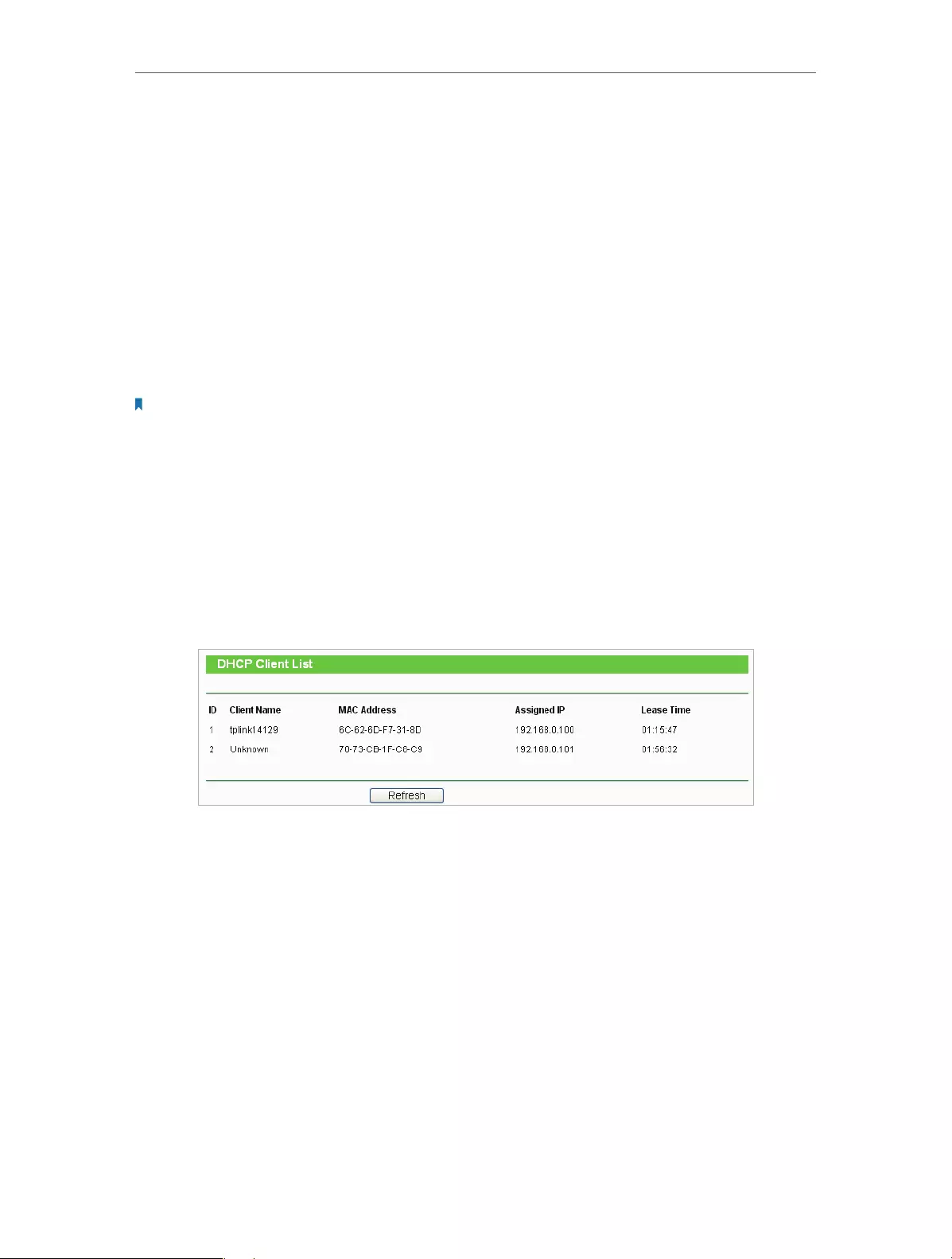
4. 5. DHCP
By default, the DHCP (Dynamic Host Configuration Protocol) Server is enabled and the
router acts as a DHCP server; it dynamically assigns TCP/IP parameters to client devices
from the IP Address Pool. You can change the settings of DHCP Server if necessary, and
you can reserve LAN IP addresses for specified client devices.
4. 5. 1. DHCP Settings
1. Visit http://tplinkwifi.net, and log in with the username and password you set for
the router.
2. Go to DHCP > DHCP Settings.
3. Specify DHCP server settings and click Save.
• DHCP Server — Enable or disable the DHCP server. If disabled, you must have another
DHCP server within your network or else you must configure the computer manually.
• Start IP Address — Specify an IP address for the DHCP Server to start with when
assigning IP addresses. 192.168.0.100 is the default start address.
• End IP Address — Specify an IP address for the DHCP Server to end with when assigning
IP addresses. 192.168.0.199 is the default end address.
34
Chapter 4 Congure
• Address Lease Time — The Address Lease Time is the amount of time a network user
will be allowed to connect to the Router with the current dynamic IP Address. When
time is up, the user will be automatically assigned a new dynamic IP address. The
range of the time is 1 ~ 2880 minutes. The default value is 120.
• Default Gateway (Optional) — It is suggested to input the IP address of the LAN port of
the Router. The default value is 192.168.0.254.
• Default Domain (Optional) — Input the domain name of your network.
• Primary DNS (Optional) — Input the DNS IP address provided by your ISP.
• Secondary DNS (Optional) — Input the IP address of another DNS server if your ISP
provides two DNS servers.
Note:
To use the DHCP server function of the router, you must configure all computers on the LAN as Obtain an IP Address
automatically.
4. 5. 2. DHCP Client List
1. Visit http://tplinkwifi.net, and log in with the username and password you set for
the router.
2. Go to DHCP > DHCP Client List to view the information of the clients connected to
the router.
• Client Name — The name of the DHCP client.
• MAC Address — The MAC address of the DHCP client.
• Assigned IP — The IP address that the router has allocated to the DHCP client.
• Lease Time — The time of the DHCP client leased. After the dynamic IP address has
expired, a new dynamic IP address will be automatically assigned to the user.
You cannot change any of the values on this page. To update this page and show the
current attached devices, click Refresh.
4. 5. 3. Address Reservation
You can reserve an IP address for a specific client. When you have specified a reserved
IP address for a PC on the LAN, this PC will always receive the same IP address each time
when it accesses the DHCP server.
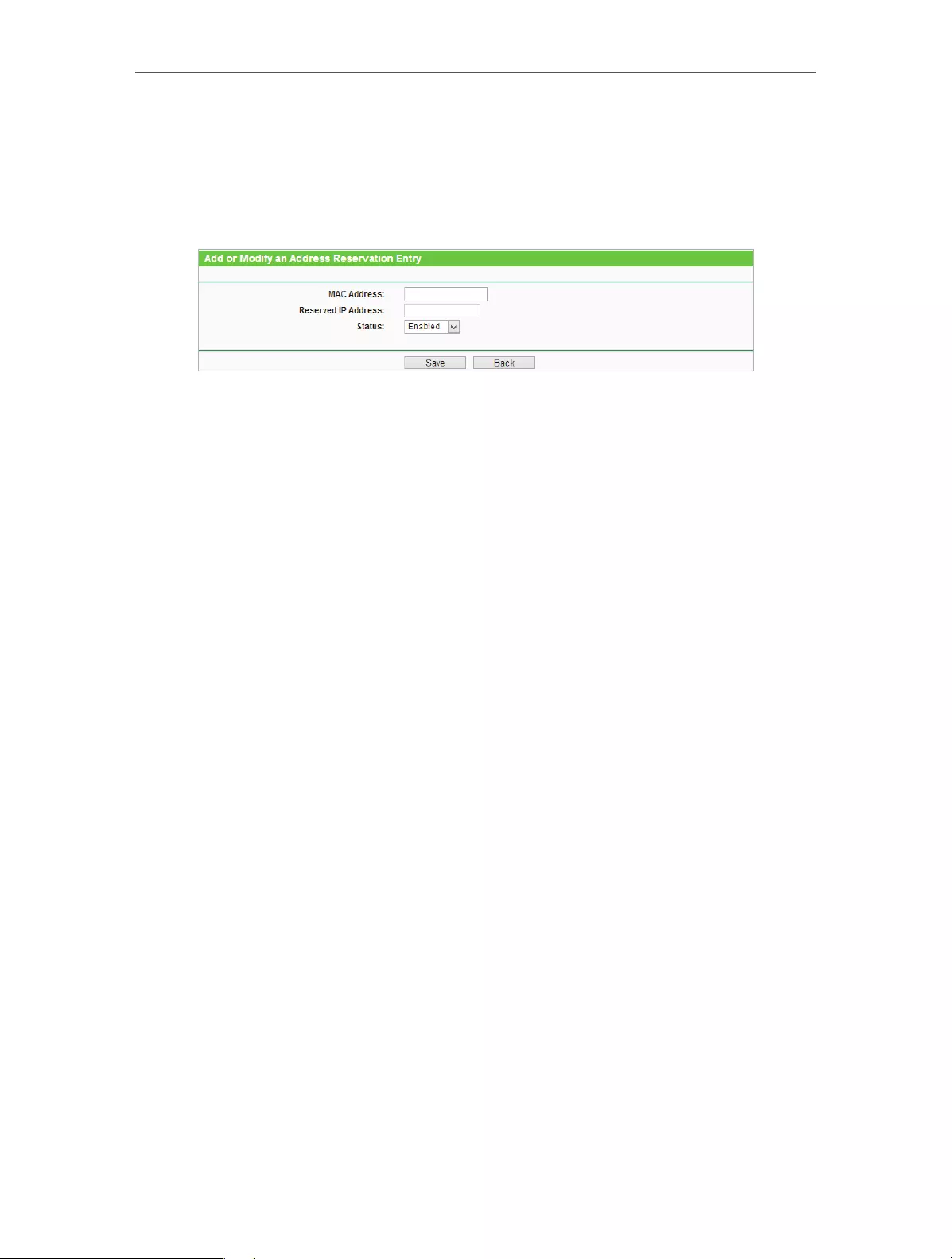
35
Chapter 4 Congure
1. Visit http://tplinkwifi.net, and log in with the username and password you set for
the router.
2. Go to DHCP > Address Reservation.
3. Click Add New and fill in the blank.
1 ) Enter the MAC address (in XX-XX-XX-XX-XX-XX format) of the client for which
you want to reserve an IP address.
2 ) Enter the IP address (in dotted-decimal notation) which you want to reserve for
the client.
3 ) Leave the status as Enabled.
4 ) Click Save.
4. 6. Forwarding
The router’s NAT (Network Address Translation) feature makes the devices in the LAN
use the same public IP address to communicate in the Internet, which protects the
local network by hiding IP addresses of the devices. However, it also brings about the
problem that external hosts cannot initiatively communicate with the specified devices
in the local network.
With the forwarding feature, the router can traverse the isolation of NAT so that clients
on the Internet can reach devices in the LAN and realize some specific functions.
The TP-LINK router includes four forwarding rules. If two or more rules are set, the
priority of implementation from high to low is Virtual Servers, Port Triggering, UPNP
and DMZ.
4. 6. 1. Virtual Servers
When you build up a server in the local network and want to share it on the Internet,
Virtual Servers can realize the service and provide it to Internet users. At the same time
virtual servers can keep the local network safe as other services are still invisible from
the Internet.
Virtual Servers can be used to set up public services in your local network, such as HTTP,
FTP, DNS, POP3/SMTP and Telnet. Different service uses different service port. Port 80

36
Chapter 4 Congure
is used in HTTP service, port 21 in FTP service, port 25 in SMTP service and port 110 in
POP3 service. Please verify the service port number before the configuration.
Share my personal website I’ve built in local network with my
friends through the Internet.
For example, the personal website has been built in my home
PC (192.168.0.100). I hope that my friends in the Internet can
visit my website in some way. My PC is connected to the router
with the WAN IP address 218.18.232.154.
Router
WAN: 218.18.232.154
LAN
Home
Personal Website
1. Set your PC to a static IP address, for example 192.168.0.100.
2. Visit http://tplinkwifi.net, and log in with the username and
password you set for the router.
3. Go to Forwarding > Virtual Servers.
4. Click Add New. Select HTTP from the Common Service
Port list. The service port, internal port and protocol will be
automatically filled with contents. Enter the PC’s IP address
192.168.0.100 in the IP Address field.
5. Leave the status as Enabled and click Save.
Note:
• It is recommended to keep the default settings of Internal Port and Protocol if
you are not clear about which port and protocol to use.
• If the service you want to use is not in the Common Service Port list, you can enter
the corresponding parameters manually. You should verify the port number that
the service needs.
• You can add multiple virtual server rules if you want to provide several services in
a router. Please note that the Service Port should not be overlapped.
Users in the Internet can enter http:// WAN IP (in this example:
I want to:
Done!
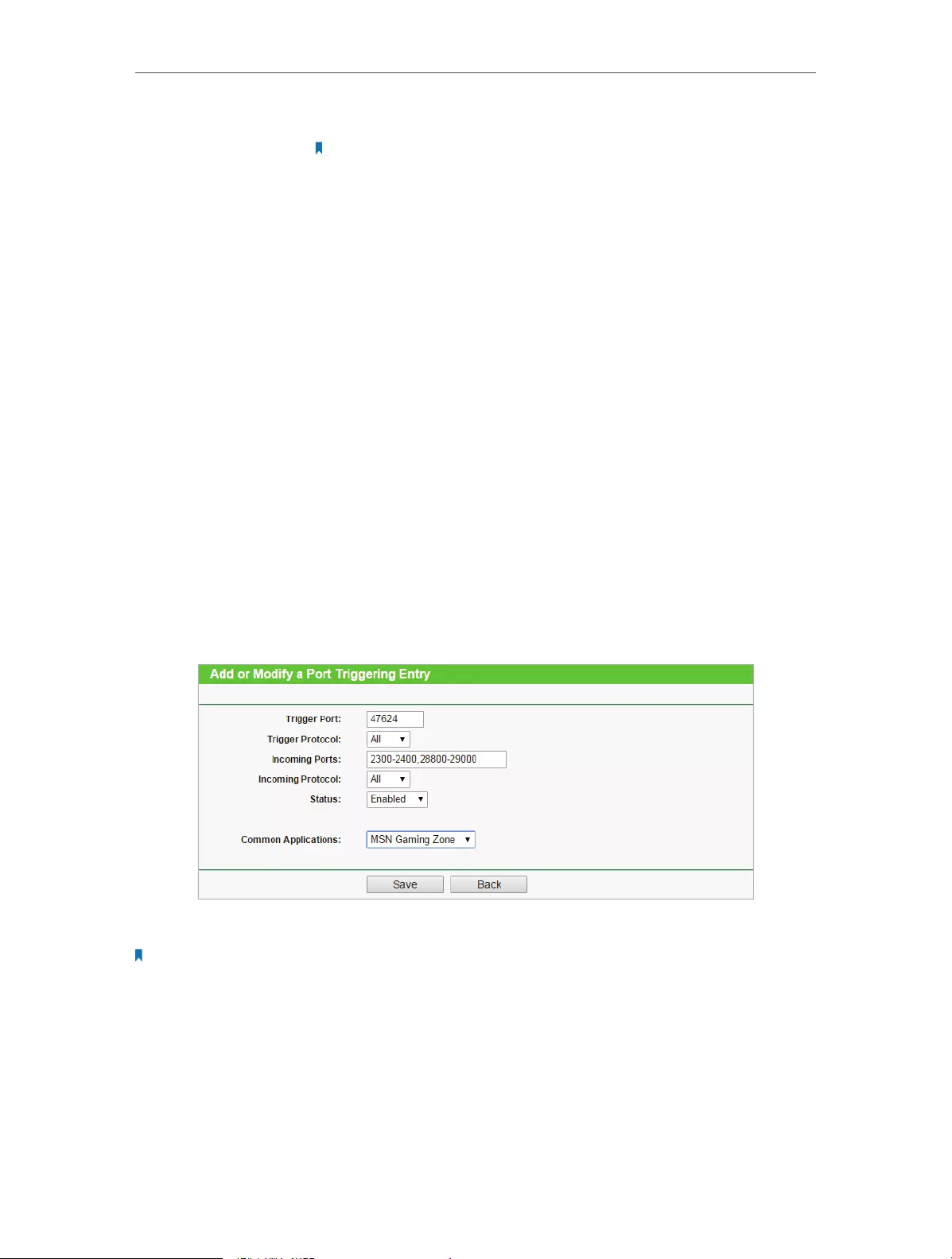
37
Chapter 4 Congure
http:// 218.18.232.154) to visit your personal website.
Note:
If you have changed the default Service Port, you should use http:// WAN IP: Service
Port to visit the website.
4. 6. 2. Port Triggering
Port triggering can specify a triggering port and its corresponding external ports.
When a host in the local network initiates a connection to the triggering port, all the
external ports will be opened for subsequent connections. The router can record the IP
address of the host. When the data from the Internet return to the external ports, the
router can forward them to the corresponding host. Port triggering is mainly applied
to online games, VoIPs and video players. Common applications include MSN Gaming
Zone, Dialpad and Quick Time 4 players, etc.
Follow the steps below to configure the port triggering rules:
1. Visit http://tplinkwifi.net, and log in with the username and password you set for
the router.
2. Go to Forwarding > Port Triggering.
3. Click Add New. Select the desired application from the Common Applications list.
The trigger port amd incoming ports will be automatically filled with contents. The
following picture takes application MSN Gaming Zone as an example.
4. Leave the status as Enabled and click Save.
Note:
• You can add multiple port triggering rules according to your network need.
• The triggering ports can not be overlapped.
• If the application you need is not listed in the Common Applications list, please enter the parameters manually.
You should verify the incoming ports the application uses first and enter them in Incoming Ports field. You can
input at most 5 groups of ports (or port sections). Every group of ports must be set apart with “,”. For example,
2000-2038, 2050-2051, 2085, 3010-3030.

38
Chapter 4 Congure
4. 6. 3. DMZ
When a PC is set to be a DMZ (Demilitarized Zone) host in the local network, it is totally
exposed to the Internet, which can realize the unlimited bidirectional communication
between internal hosts and external hosts. The DMZ host becomes a virtual server with
all ports opened. When you are not clear about which ports to open in some special
applications, such as IP camera and database software, you can set the PC to be a DMZ
host.
Note:
DMZ is more applicable in the situation that users are not clear about which ports to open. When it is enabled, the
DMZ host is totally exposed to the Internet, which may bring some potential safety hazard. If DMZ is not in use,
please disable it in time.
Make the home PC join the Internet online game without port
restriction.
For example, due to some port restriction, when playing the
online games, you can login normally but cannot join a team
with other players. To solve this problem, set your PC as a DMZ
with all ports opened.
1. Assign a static IP address to your PC, for example
192.168.0.100.
2. Visit http://tplinkwifi.net, and log in with the username and
password you set for the router.
3. Go to Forwarding > DMZ.
4. Select Enable and enter the IP address 192.168.0.100 in the
DMZ Host IP Address filed.
5. Click Save.
You’ve set your PC to a DMZ host and now you can make a team
to game with other players.
4. 6. 4. UPnP
The UPnP (Universal Plug and Play) protocol allows the applications or host devices
to automatically find the front-end NAT device and send request to it to open the
corresponding ports. With UPnP enabled, the applications or host devices in the
both sides of the NAT device can freely communicate with each other realizing the
I want to:
How can I
do that?
Done!

39
Chapter 4 Congure
seamless connection of the network. You may need to enable the UPnP if you want
to use applications for multiplayer gaming, peer-to-peer connections, real-time
communication (such as VoIP or telephone conference) or remote assistance, etc.
Tips:
• UPnP is enabled by default in this router.
• Only the application supporting UPnP protocol can use this feature.
• UPnP feature needs the support of operating system (e.g. Windows Vista/ Windows 7/ Windows 8, etc. Some of
operating system need to install the UPnP components).
For example, when you connect your Xbox to the router which is connected to the
Internet to play online games, UPnP will send request to the router to open the
corresponding ports allowing the following data penetrating the NAT to transmit.
Therefore, you can play Xbox online games without a hitch.
RouterXbox
LAN WAN
If necessary, you can follow the steps to change the status of UPnP.
1. Visit http://tplinkwifi.net, and log in with the username and password you set for
the router.
2. Go to Forwarding > UPnP.
3. Click Disable or Enable according to your needs.
4. 7. Security
This function allows you to protect your home network from cyber attacks and
unauthorized users by implementing these network security functions.

40
Chapter 4 Congure
4. 7. 1. Basic Security
1. Visit http://tplinkwifi.net, and log in with the username and password you set for
the router.
2. Go to Security > Basic Security, and you can enable or disable the security functions.
• Firewall — A firewall protects your network from Internet attacks.
• SPI Firewall — SPI (Stateful Packet Inspection, also known as dynamic packet
filtering) helps to prevent cyber attacks by tracking more state per session. It
validates that the traffic passing through the session conforms to the protocol.
SPI Firewall is enabled by default.
• VPN — VPN Passthrough must be enabled if you want to allow VPN tunnels using IPSec,
PPTP or L2TP protocols to pass through the router’s firewall.
• PPTP Passthrough — Point-to-Point Tunneling Protocol (PPTP) allows the Point-
to-Point Protocol (PPP) to be tunneled through an IP network. If you want
to allow PPTP tunnels to pass through the router, you can keep the default
(Enabled).
• L2TP Passthrough — Layer 2 Tunneling Protocol (L2TP) is the method used to
enable Point-to-Point sessions via the Internet on the Layer 2 level. If you want
to allow L2TP tunnels to pass through the router, you can keep the default
(Enabled).

41
Chapter 4 Congure
• IPSec Passthrough — Internet Protocol Security (IPSec) is a suite of protocols for
ensuring private, secure communications over Internet Protocol (IP) networks,
through the use of cryptographic security services. If you want to allow IPSec
tunnels to pass through the router, you can keep the default (Enabled).
• ALG — It is recommended to enable Application Layer Gateway (ALG) because ALG
allows customized Network Address Translation (NAT) traversal filters to be plugged
into the gateway to support address and port translation for certain application layer
“control/data” protocols such as FTP, TFTP, H323 etc.
• FTP ALG — To allow FTP clients and servers to transfer data across NAT, keep the
default Enable.
• TFTP ALG — To allow TFTP clients and servers to transfer data across NAT, keep
the default Enable.
• H323 ALG — To allow Microsoft NetMeeting clients to communicate across NAT,
keep the default Enable.
• RTSP ALG — To allow some media player clients to communicate with some
streaming media servers across NAT, click Enable.
• SIP ALG — To allow some multimedia clients to communicate across NAT, click
Enable.
3. Click Save.
4. 7. 2. Advanced Security
1. Visit http://tplinkwifi.net, and log in with the username and password you set for
the router.
2. Go to Security > Advanced Security, and you can protect the router from being
attacked by ICMP-Flood, UDP Flood and TCP-SYN Flood.

42
Chapter 4 Congure
• Packets Statistics Interval (5~60) — The default value is 10. Select a value between 5 and
60 seconds from the drop-down list. The Packets Statistics Interval value indicates the
time section of the packets statistics. The result of the statistics is used for analysis by
SYN Flood, UDP Flood and ICMP-Flood.
• DoS Protection — Denial of Service protection. Select Enable or Disable to enable or
disable the DoS protection function. Only when it is enabled, will the flood filters be
enabled.
Note:
Dos Protection will take effect only when the Statistics in System Tool > Statistics is enabled.
• Enable ICMP-FLOOD Attack Filtering -Check the box to enable or disable this function.
• ICMP-FLOOD Packets Threshold (5~3600) — The default value is 50. Enter a value
between 5 ~ 3600. When the number of the current ICMP-FLOOD packets is beyond
the set value, the router will startup the blocking function immediately.
• Enable UDP-FLOOD Filtering — Check the box to enable or disable this function.
• UDP-FLOOD Packets Threshold (5~3600) — The default value is 500. Enter a value
between 5 ~ 3600. When the number of the current UPD-FLOOD packets is beyond
the set value, the router will startup the blocking function immediately.
• Enable TCP-SYN-FLOOD Attack Filtering —Check the box to enable or disable this
function.
• TCP-SYN-FLOOD Packets Threshold (5~3600) — The default value is 50. Enter a value
between 5 ~ 3600. When the number of the current TCP-SYN-FLOOD packets is
beyond the set value, the router will startup the blocking function immediately.
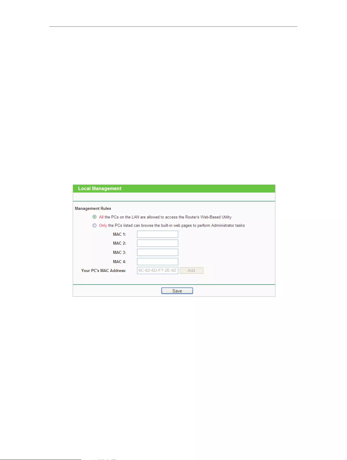
43
Chapter 4 Congure
• Ignore Ping Packet From WAN Port — The default setting is disabled. If enabled, the
ping packet from the Internet cannot access the router.
• Forbid Ping Packet From LAN Port — The default setting is disabled. If enabled, the
ping packet from LAN cannot access the router. This function can be used to defend
against some viruses.
3. Click Save.
4. Click Blocked DoS Host List to display the DoS host table by blocking.
4. 7. 3. Local Management
1. Visit http://tplinkwifi.net, and log in with the username and password you set for
the router.
2. Go to Security > Local Management, and you can block computers in LAN from
accessing the router.
For example, if you want to allow PCs with specific MAC addresses to access the router’s
web management page locally from inside the network, please follow the instructions
below:
1 ) Select Only the PCs listed can browse the built-in web pages to perform
Administrator tasks.
2 ) Enter the MAC address of each PC separately. The format of the MAC address
is XX—XX—XX—XX—XX-XX (X is any hexadecimal digit). Only the PCs with the listed
MAC addresses can use the password to browse the built-in web pages to
perform administrator tasks.
3 ) Click Add, and your PC’s MAC address will also be listed.
4 ) Click Save.

44
Chapter 4 Congure
Note:
If your PC is blocked but you want to access the router again, press and hold the Reset button to reset the router to
the factory defaults.
4. 7. 4. Remote Management
1. Visit http://tplinkwifi.net, and log in with the username and password you set for
the router.
2. Go to Security > Remote Management, and you can manage your router from a
remote device via the Internet.
• Web Management Port — Web browser access normally uses the standard HTTP
service port 80. This router’s default remote management web port number is 80.
For higher security, you can change the remote management web port to a custom
port by entering a number between 1 and 65534 but do not use the number of any
common service port.
• Remote Management IP Address — This is the address you will use when accessing
your router via a remote device. This function is disabled when the IP address is set
to the default value of 0.0.0.0. To enable this function, change 0.0.0.0 to a valid IP
address. If it is set to 255.255.255.255, then all the remote devices can access the
router from the Internet.
Note:
• To access the router, enter your router’s WAN IP address in your browser’s address bar, followed by a colon and the
custom port number. For example, if your router’s WAN address is 202.96.12.8, and the port number used is 8080,
please enter http://202.96.12.8:8080 in your browser. Later, you may be asked for the router’s password. After
successfully entering the username and password, you will be able to access the router’s web management page.
• Be sure to change the router’s default password for security purposes.
4. 8. Parental Controls
Parental Controls allows you to block inappropriate and malicious websites, and control
access to specific websites at specific time for your children’s devices.
For example, you want the children’s PC with the MAC address 00-11-22-33-44-AA can
access www.tp-link.com on Saturday only while the parent PC with the MAC address
00-11-22-33-44-BB is without any restriction.

45
Chapter 4 Congure
1. Visit http://tplinkwifi.net, and log in with the username and password you set for
the router.
2. Go to Access Control > Schedule.
3. Click Add New to create a new schedule entry with Schedule Description as
Schedule_1, Day as Sat and Time as all day-24 hours.
4. Go to Parental Control.
5. Select Enable and enter the MAC address 00-11-22-33-44-BB in the MAC Address of
Parental PC field.
6. Click Add New.
7. Enter appropriate parameters in corresponding fields.
• Enter 00-11-22-33-44-AA in the MAC Address of Children’s PC field.
• Enter Allow TP-LINK in the Website Description field.
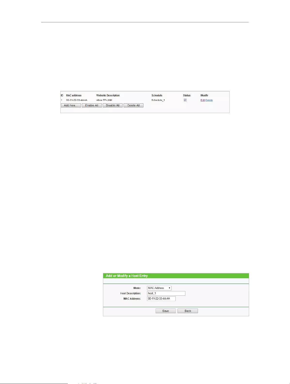
46
Chapter 4 Congure
• Enter www.tp-link.com in the Allowed Website Name field.
• Select Schedule_1 you created just now from the Effective Time drop-down
list.
• In the Status field, select Enable.
8. Click Save.
Then you can go back to the Parental Control Settings page to check the following list.
4. 9. Access Control
Access Control is used to deny or allow specific client devices to access your network
with access time and content restrictions.
Deny or allow specific client devices to access my network with
access tiem and content restrictions.
For example, If you want to restrict the internet activities of
host with MAC address 00-11-22-33-44-AA in the LAN to access
www.tp-link.com only, please follow the steps below:
1. Visit http://tplinkwifi.net, and log in with the username and
password you set for the router.
2. Go to Access Control > Host and configure the host settings:
1 ) Click Add New.
2 ) Select MAC Address as the mode type. Create a unique
description (e.g. host_1) for the host in the Host
Description field and enter 00-11-22-33-44-AA in the
MAC Address filed.
3 ) Click Save.
3. Go to Access Control > Target and configure the target
settings:
1 ) Click Add New.
I want to:
How can I
do that?
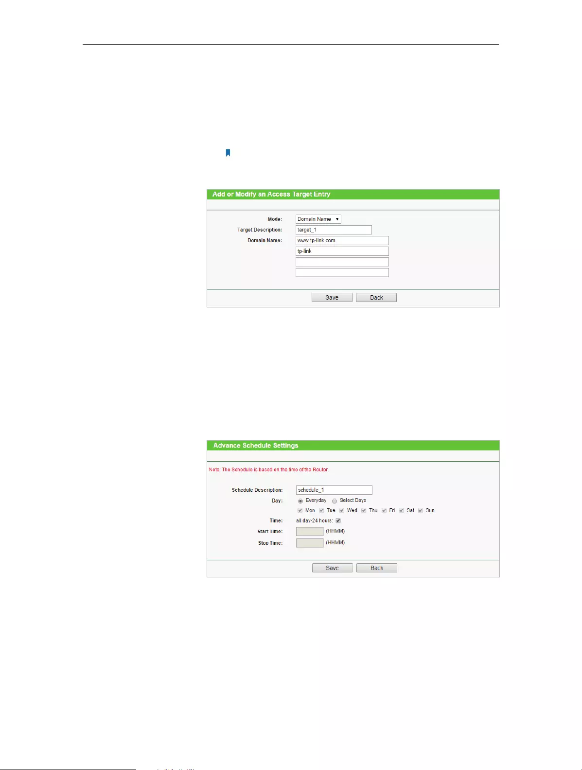
47
Chapter 4 Congure
2 ) Select Domain Name as the mode type. Create a unique
description (e.g. target_1) for the target in the Target
Description field and enter the domain name, either the
full name or the keywords (for example TP-LINK) in the
Domain Name field.
Note:
Any domain name with keywords in it (e.g. www.tp-link.com) will be blocked
or allowed.
3 ) Click Save.
4. Go to Access Control > Schedule and configure the schedule
settings:
1 ) Click Add New.
2 ) Create a unique description (e.g. schedule_1) for the
schedule in the Schedule Description field and set the
day(s) and time period.
3 ) Click Save.
5. Go to Access Control > Rule and add a new access control
rule.
1 ) Click Add New.
2 ) Give a name for the rule in the Rule Name field. Select
host_1 from the host drop-down list; select target_1

48
Chapter 4 Congure
from the target drop-down list; select schedule_1 from
the schedule drop-down list.
3 ) Leave the status as Enabled as click Save.
6. Select Enable Internet Access Control to enable Access
Control function.
7. Select Allow the packets specified by any enabled access
control policy to pass through the Router as the default filter
policy and click Save.
Now only the specific host(s) can visit the target(s) within the
scheduled time period.
4. 10. Advanced Routing
Static Routing is a form of routing that is configured manually by a network administrator
or a user by adding entries into a routing table. The manually-configured routing
information guides the router in forwarding data packets to the specific destination.
4. 10. 1. Static Routing List
1. Visit http://tplinkwifi.net, and log in with the username and password you set for
the router.
2. Go to Advanced Routing > Static Routing.
¾To add static routing entries:
1. Click Add New.
Done!

49
Chapter 4 Congure
2. Enter the following information.
• Destination Network — The Destination Network is the address of the network
or host that you want to assign to a static route.
• Subnet Mask — The Subnet Mask determines which portion of an IP Address is
the network portion, and which portion is the host portion.
• Default Gateway — This is the IP Address of the default gateway device that
allows for the contact between the router and the network or host.
3. Select Enabled or Disabled for this entry on the Status drop-down list.
4. Click Save.
You can also do the following operations to modify the current settings.
• Click Delete to delete the entry.
• Click Enable All to enable all the entries.
• Click Disable All to disable all the entries.
• Click Delete All to delete all the entries.
• Click Previous to view the information on the previous screen and Next to view the
information on the next screen.
4. 10. 2. System Routing Table
1. Visit http://tplinkwifi.net, and log in with the username and password you set for
the router.
2. Go to Advanced Routing > System Routing Table, and you can view all the valid
route entries in use.

50
Chapter 4 Congure
• Destination Network — The Destination Network is the address of the network or host
to which the static route is assigned.
• Subnet Mask — The Subnet Mask determines which portion of an IP address is the
network portion, and which portion is the host portion.
• Gateway — This is the IP address of the gateway device that allows for contact between
the Router and the network or host.
• Interface — This interface tells you whether the Destination IP Address is on the LAN &
WLAN (internal wired and wireless networks), or the WAN(Internet).
• Click Refresh to refresh the data displayed.
4. 11. Bandwidth Control
4. 11. 1. Control Settings
1. Visit http://tplinkwifi.net, and log in with the username and password you set for
the router.
2. Go to Bandwidth Control > Control Settings.
The values you configure for the Egress Bandwidth and Ingress Bandwidth should be
less than 100,000Kbps. For optimal control of the bandwidth, please select the right
Line Type and consult your ISP for the total egress and ingress bandwidth.
• Enable Bandwidth Control — Check this box so that the Bandwidth Control settings
can take effect.
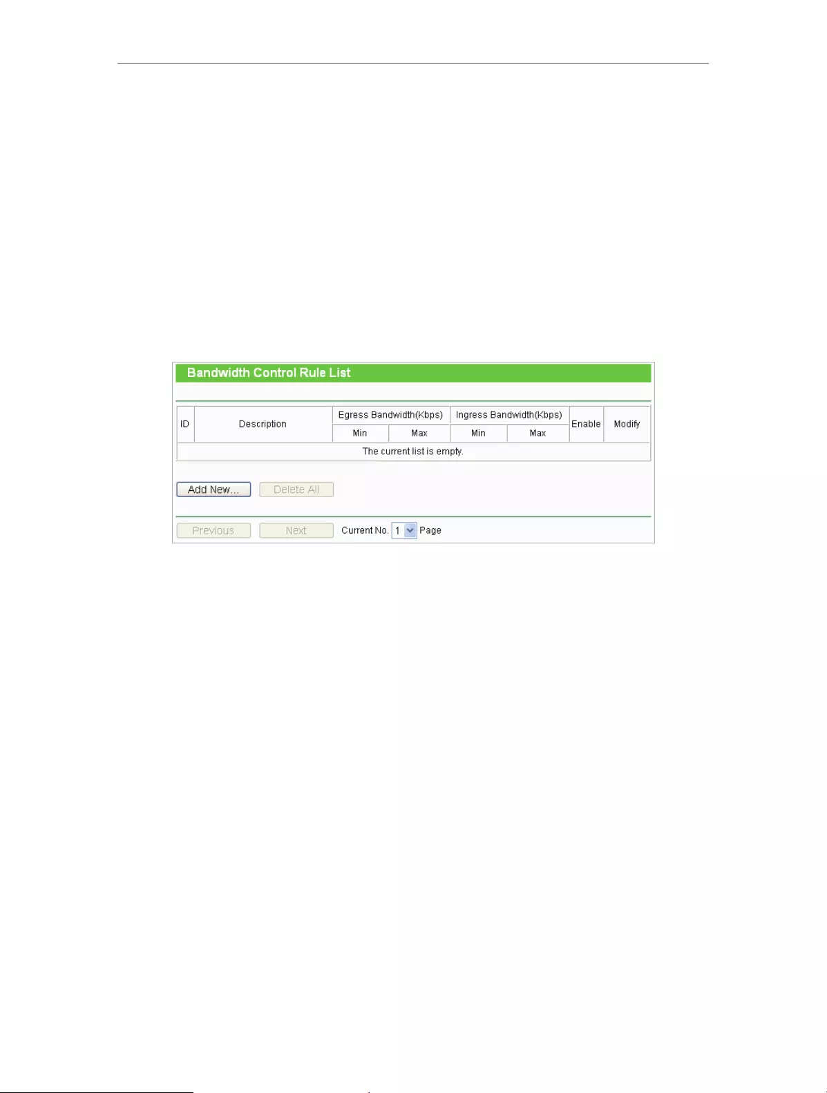
51
Chapter 4 Congure
• Line Type — Select the right type for you network connection. If you are not sure,
please consult your ISP.
• Egress Bandwidth — The upload speed through the WAN port.
• Ingress Bandwidth — The download speed through the WAN port.
4. 11. 2. Rules List
1. Visit http://tplinkwifi.net, and log in with the username and password you set for
the router.
2. Go to Bandwidth Control > Rules List, and you can view and configure the Bandwidth
Control rules.
• Description — This is the information about the rules such as address range.
• Egress Bandwidth — This field displays the max and min upload bandwidth through
the WAN port. The default is 0.
• Ingress Bandwidth — This field displays the max and min download bandwidth through
the WAN port. The default is 0.
• Enable — This field displays the status of the rule.
• Modify — Click Modify/Delete to edit/delete the rule.
¾To add a Bandwidth control rule:
1. Click Add New.
2. Enter the information like the figure shown below.

52
Chapter 4 Congure
3. Click Save.
4. 12. IP&MAC Binding
IP & MAC Binding, namely, ARP (Address Resolution Protocol) Binding, is used to bind
a network device’s IP address to its MAC address. This will prevent ARP spoofing and
other ARP attacks by denying network access to a device with a matching IP address in
the ARP list, but with an unrecognized MAC address.
4. 12. 1. Binding Settings
1. Visit http://tplinkwifi.net, and log in with the username and password you set for
the router.
2. Go to IP & MAC Binding > Binding Settings.
3. Select Enable for ARP Binding.
4. Click Save.
¾To add IP & MAC Binding entries:
1. Click Add New.
2. Select the Bind checkbox.

53
Chapter 4 Congure
3. Enter the MAC address and IP address.
4. Click Save.
¾To modify or delete an existing entry:
1. Find the desired entry in the table.
2. Click Modify or Delete in the Modify column.
¾To find an existing entry:
1. Click Find.
2. Enter the MAC address or IP address in the corresponding field.
3. Click Find on this page as shown below.
4. 12. 2. ARP List
To manage a device, you can observe the device in the LAN by checking its MAC address
and IP address on the ARP list, and you can also configure the items. This page displays
the ARP List which shows all the existing IP & MAC Binding entries.
• MAC Address — The MAC address of the listed computer in the LAN.

54
Chapter 4 Congure
• IP Address — The assigned IP address of the listed computer in the LAN.
• Status — Indicates whether or not the MAC and IP addresses are bound.
• Configure — Load or delete an item.
• Load — Load the item to the IP & MAC Binding list.
• Delete — Delete the item.
• Click Bind All to bind all the current items.
• Click Load All to load all items to the IP & MAC Binding list.
• Click Refresh to refresh all items.
Note:
An item can not be loaded to the IP & MAC Binding list if the IP address of the item has been loaded before. Error
warning will prompt as well. Likewise, Load All only loads the items without interference to the IP & MAC Binding list.
4. 13. Dynamic DNS
The router offers the DDNS (Dynamic Domain Name System) feature, which allows the
hosting of a website, FTP server, or e-mail server with a fixed domain name (named
by yourself) and a dynamic IP address. Thus your friends can connect to your server
by entering your domain name no matter what your IP address is. Before using this
feature, you need to sign up for DDNS service providers such as www.comexe.cn, www.
dyndns.org, or www.no-ip.com. The Dynamic DNS client service provider will give you
a password or key.
1. Visit http://tplinkwifi.net, and log in with the username and password you set for
the router.
2. Go to Dynamic DNS.
Comexe.cn DDNS
If the dynamic DNS Service Provider you select is www.comexe.cn, the following page
will appear.
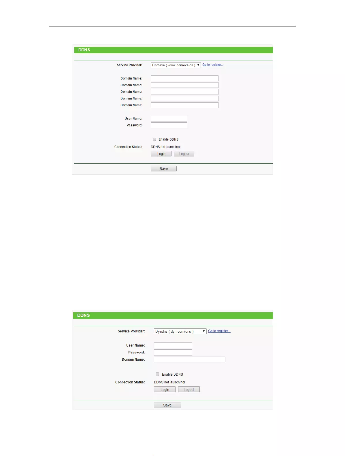
55
Chapter 4 Congure
To set up for DDNS, follow these instructions:
1. Enter the Domain Name received from your dynamic DNS service provider.
2. Enter the User Name for your DDNS account.
3. Enter the Password for your DDNS account.
4. Click Login.
5. Click Save.
• Connection Status — The status of the DDNS service connection is displayed here.
• Logout — Click Logout to log out of the DDNS service.
Dyndns.org DDNS
If the dynamic DNS Service Provider you select is www.dyn.com, the following page
will appear.
To set up for DDNS, follow these instructions:
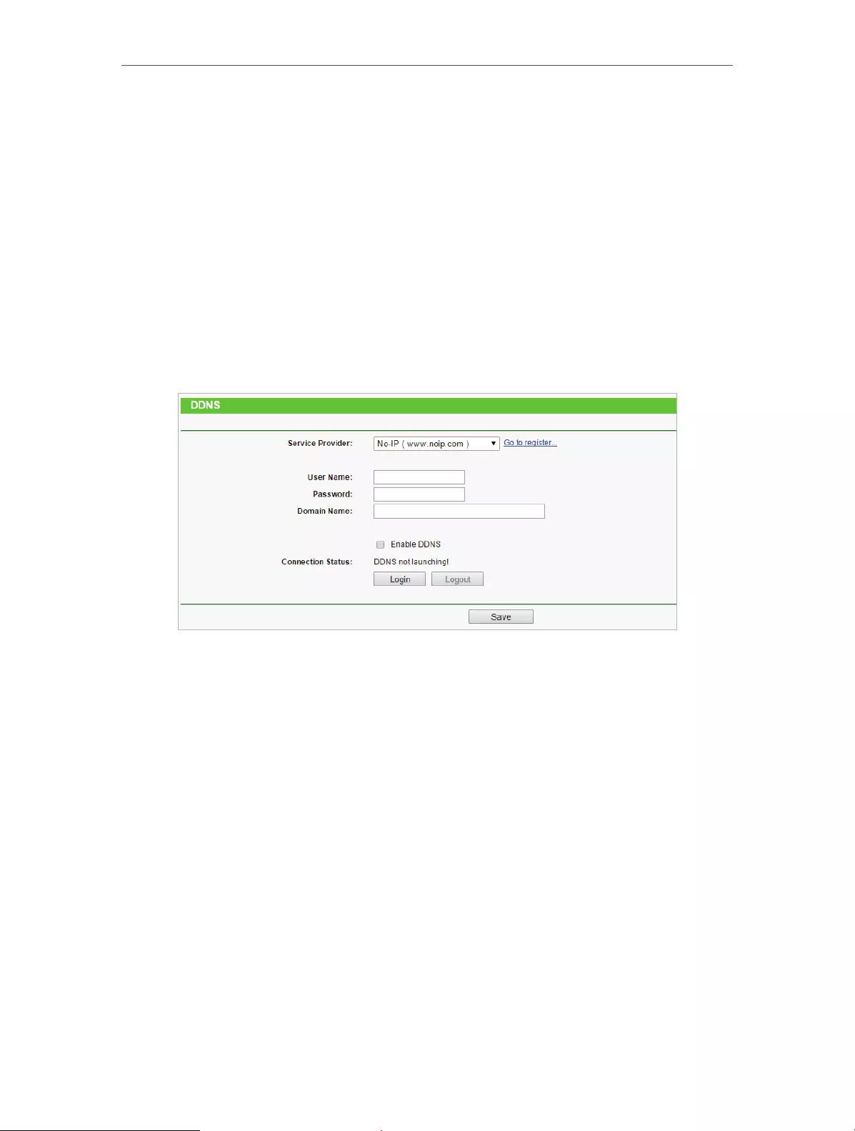
56
Chapter 4 Congure
1. Enter the User Name for your DDNS account.
2. Enter the Password for your DDNS account.
3. Enter the Domain Name you received from dynamic DNS service provider here.
4. Click Login.
5. Click Save.
• Connection Status — The status of the DDNS service connection is displayed here.
• Logout — Click Logout to log out of the DDNS service.
No-ip.com DDNS
If the dynamic DNS Service Provider you select is www.noip.com, the following page
will appear.
To set up for DDNS, follow these instructions:
1. Enter the User Name for your DDNS account.
2. Enter the Password for your DDNS account.
3. Enter the Domain Name you received from dynamic DNS service provider.
4. Click Login.
5. Click Save.
• Connection Status — The status of the DDNS service connection is displayed here.
• Logout — Click Logout to log out of the DDNS service.
4. 14. IPv6 Support
This function allows you to enable IPv6 function and set up the parameters of the
router’s Wide Area Network (WAN) and Local Area Network (LAN).
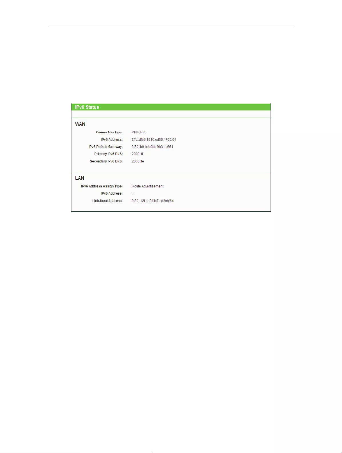
57
Chapter 4 Congure
4. 14. 1. IPv6 Status
1. Visit http://tplinkwifi.net, and log in with the username and password you set for
the router.
2. Go to IPv6 Support > IPv6 Status, and you can view the current IPv6 status
information of the router.
• WAN — This section shows the current IPv6 information of the router’s WAN port,
including Connection Type, IPv6 Address information, IPv6 Default Gateway, Primary
IPv6 DNS and Secondary IPv6 DNS.
• LAN — This section shows the current IPv6 information of the router’s LAN port,
including IPv6 Address Assign Type, IPv6 Address and Link-local Address.
4. 14. 2. IPv6 Setup
1. Visit http://tplinkwifi.net, and log in with the username and password you set for
the router.
2. Go to IPv6 Support > IPv6 Setup.

58
Chapter 4 Congure
3. Select the WAN Connection Type according to your ISP network topolopy:
• SLAAC — Connections which use RADVD IPv6 address assignment.
• DHCPv6 — Connections which use dynamic IPv6 address assignment.
• Static IPv6 — Connections which use static IPv6 address assignment.
• PPPoEv6 — Connections which use PPPoEV6 that requires a username and
password.
• Tunnel 6to4 — Connections which use 6to4 address assignment.
SLAAC
• IPv6 Address — The IPv6 address assigned by your ISP dynamically.
• IPv6 Address Prefix — Display the IPv6 prefix length in dotted-decimal notation
provided by your ISP.
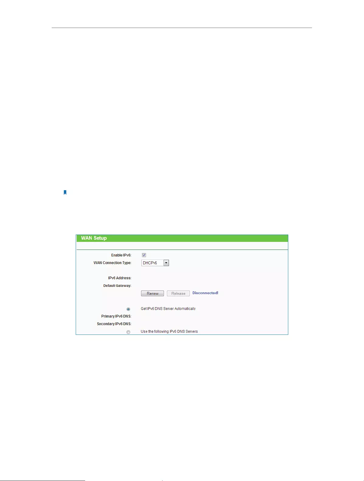
59
Chapter 4 Congure
• Default Gateway — Display the default gateway in colon-hexadecimal notation
provided by your ISP.
• Connect — Click Connect to connect immediately.
• Disconnect — Click Disconnect to disconnect immediately.
• Get IPv6 DNS Server Automatically — If your ISP does not give you any DNS IPv6
address, keep the default selection Get IPv6 DNS Server Automatically, and the
DNS servers will be assigned from ISP dynamically.
• Primary IPv6 DNS — Enter the DNS IPv6 address in dotted-decimal notation
provided by your ISP.
• Secondary IPv6 DNS — Enter another DNS IPv6 address in dotted-decimal
notation provided by your ISP.
• Use the following IPv6 DNS Servers — If your ISP gives you one or two DNS IPv6
addresses, select Use the following IPv6 DNS Servers and enter the Primary
IPv6 DNS and Secondary IPv6 DNS in the corresponding fields.
Note:
If you get “Address not found error” when you access a web site, it is likely that your DNS servers are set up
improperly. You should contact your ISP to get DNS server addresses.
DHCPv6
• IPv6 Address — The IPv6 address assigned by your ISP dynamically.
• Default Gateway — Display the default gateway in colon-hexadecimal notation
provided by your ISP.
• Renew — Click Renew to renew the IPv6 parameters from your ISP.
• Release — Click Release to release the IPv6 parameters from your ISP.
• Get IPv6 DNS Server Automatically — If your ISP does not give you any DNS IPv6
address, keep the default selection Get IPv6 DNS Server Automatically, and the
DNS servers will be assigned from ISP dynamically.
• Primary IPv6 DNS — Enter the DNS IPv6 address in dotted-decimal notation
provided by your ISP.
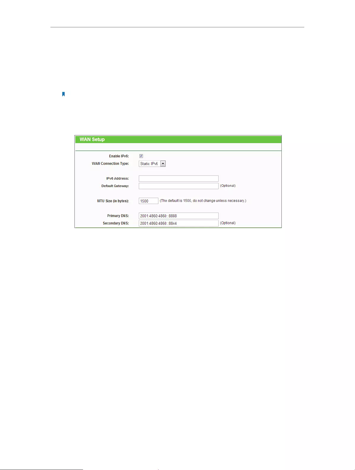
60
Chapter 4 Congure
• Secondary IPv6 DNS — Enter another DNS IPv6 address in dotted-decimal
notation provided by your ISP.
• Use the following IPv6 DNS Servers — If your ISP gives you one or two DNS IPv6
addresses, select Use the following IPv6 DNS Servers and enter the Primary
IPv6 DNS and Secondary IPv6 DNS in the corresponding fields.
Note:
If you get “Address not found error” when you access a web site, it is likely that your DNS servers are set up
improperly. You should contact your ISP to get DNS server addresses.
Static IPv6
• IPv6 Address — Enter the IPv6 address in dotted-decimal notation provided by
your ISP.
• Default Gateway — Enter the default gateway in dotted-decimal notation
provided by your ISP.
• MTU Size (in bytes) — The normal MTU (Maximum Transmission Unit) value for
most Ethernet networks is 1500 Bytes. For some ISPs, you may need to modify
the MTU. But this is rarely required, and should not be done unless you are sure
it is necessary for your ISP connection.
• Primary DNS — Enter the DNS IPv6 address in dotted-decimal notation provided
by your ISP.
• Secondary DNS — Enter another DNS IPv6 address in dotted-decimal notation
provided by your ISP.

61
Chapter 4 Congure
PPPoEv6
• PPPoE Session — The PPP session type for IPv6 connection. There are two types:
• Share with PPPoEv4 — The PPPoEv6 and PPPoEv4 use the same PPP session.
• Create a new Session — The PPPoEv6 and PPPoEv4 use different PPP
sessions. It is default to select this option.
• Username/Password — Enter the username and password provided by your ISP.
These fields are case-sensitive.
• Address Mode — The way to get the IPv6 address and prefix.
• SLAAC — Get the IPv6 address and prefix by router advertisement.
• DHCPv6 — Get the IPv6 address and prefix by DHCPv6.
• IPv6 Address — The IPv6 address assigned by your ISP dynamically.
• Default Gateway — Display the default gateway in colon-hexadecimal notation
provided by your ISP.
• MTU (in bytes) — The normal MTU (Maximum Transmission Unit) value is 1492
Bytes. For some ISPs, you may need to modify the MTU. But this is rarely
required, and should not be done unless you are sure it is necessary for your
ISP connection.
• Get IPv6 DNS Server Automatically — If your ISP does not give you any DNS IPv6
address, keep the default selection Get IPv6 DNS Server Automatically, and the
DNS servers will be assigned from ISP dynamically.
• Primary IPv6 DNS — Enter the DNS IPv6 address in dotted-decimal notation
provided by your ISP.

62
Chapter 4 Congure
• Secondary IPv6 DNS — Enter another DNS IPv6 address in dotted-decimal
notation provided by your ISP.
• Use the following IPv6 DNS Servers — If your ISP gives you one or two DNS IPv6
addresses, select Use the following IPv6 DNS Servers and enter the Primary
IPv6 DNS and Secondary IPv6 DNS in the corresponding fields.
• Connection Mode — The way to connect the ISP.
• Alway On — Connect automatically.
• Connect Manual — Connect by the user manually.
• Connect — Click Connect to connect immediately.
• Disconnect — Click Disconnect to disconnect immediately.
Tunnel 6to4
• Address/Subnet Mask/Default Gateway — The IPv4 address/ subnet mask/
default gateway assigned, in dotted-decimal notation.
• Tunnel Address — The 6to4 tunnel address created by the device to access the
IPv6 network.
• MTU Size — The normal MTU (Maximum Transmission Unit) value for most
Ethernet networks is 1480 Bytes. For some ISPs, you may need to modify the
MTU. But this is rarely required, and should not be done unless you are sure it is
necessary for your ISP connection.
• Use the following IPv6 DNS Servers — If your ISP gives you one or two DNS IPv6
addresses, select Use the following IPv6 DNS Servers and enter the Primary
IPv6 DNS and Secondary IPv6 DNS into the correct fields. Otherwise, the DNS
servers will be assigned from ISP dynamically.
• Primary IPv6 DNS — Enter the DNS IPv6 address in dotted-decimal notation
provided by your ISP.

63
Chapter 4 Congure
• Secondary IPv6 DNS — Enter another DNS IPv6 address in dotted-decimal
notation provided by your ISP.
4. Select the Address Autoconfiguration Type which determines the way how the
router assigns IPv6 address for PCs in the LAN:
• Address Autoconfiguration Type — RADVD (Router Advertisement Daemon)
and DHCPv6 (Dynamic Host Configuration Protocol for IPv6) Server.
• Site Prefix Configuration Type — The type of IPv6 address prefix.
• Delegated — Get the IPv6 address prefix from the ISP automatically, and the
device will delegate it to the LAN.
• Static — Configure the Site Prefix and Site Prefix Length manually. Please
contact your ISP to get more information before you configure them.
• LAN IPv6 Address — Display the LAN IPv6 address created by the device.
5. Click Save.
4. 15. System Tools
4. 15. 1. Time Settings
1. Visit http://tplinkwifi.net, and log in with the username and password you set for
the router.
2. Go to System Tools > Time Settings and configure the system time as needed.

64
Chapter 4 Congure
¾To set time manually:
1. Select your local time zone.
2. Enter the Date in Month/Day/Year format.
3. Enter the Time in Hour/Minute/Second format.
4. Click Save.
¾To set time automatically:
1. Select your local time zone.
2. Enter the address or domain of the NTP Server I or NTP Server II.
3. Click Get GMT to get time from the Internet if you have connected to the Internet.
¾To set Daylight Saving Time:
1. Select Enable DaylightSaving.
2. Select the start time from the drop-down list in the Start field.
3. Select the end time from the drop-down list in the End field.
4. Click Save.
Note:
This setting will be used for some time-based functions such as firewall. You must specify your time zone once you
login to the router successfully; otherwise, time-based functions will not take effect.
4. 15. 2. Diagnostic
Diagnostic is used to test the connectivity between the router and the host or other
network devices.
1. Visit http://tplinkwifi.net, and log in with the username and password you set for
the router.
2. Go to System Tools > Diagnostic.

65
Chapter 4 Congure
• Diagnostic Tool — Select one diagnostic tool.
• Ping — This diagnostic tool troubleshoots connectivity, reachability, and name
resolution to a given host or gateway.
• Tracerouter — This diagnostic tool tests the performance of a connection.
Note:
You can use ping/traceroute to test both numeric IP address or domain name. If pinging/tracerouting the IP address
is successful, but pinging/tracerouting the domain name is not, you might have a name resolution problem. In this
case, ensure that the domain name you are specifying can be resolved by using Domain Name System (DNS) queries.
• IP Address/Domain Name — Enter the destination IP address (such as 192.168.0.1) or
Domain name (such as www.tp-link.com).
• Pings Count — The number of Ping packets for a Ping connection.
• Ping Packet Size — The size of Ping packet.
• Ping Timeout — Set the waiting time for the reply of each Ping packet. If there is no
reply in the specified time, the connection is overtime.
• Traceroute Max TTL — The max number of hops for a Traceroute connection.
3. Click Start to check the connectivity of the Internet.
4. The Diagnostic Results page displays the diagnosis result. If the result is similar to
the following figure, the connectivity of the Internet is fine.
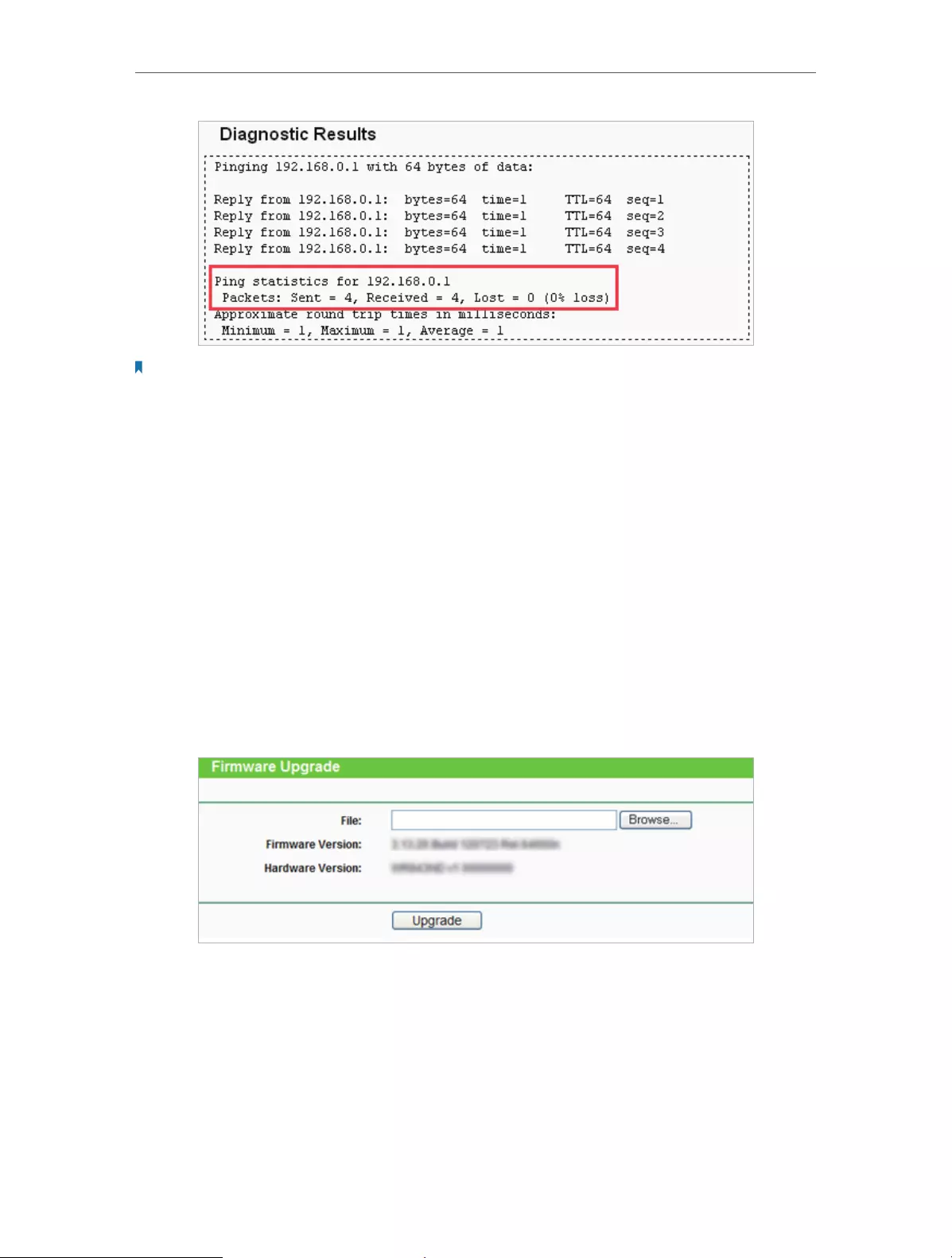
66
Chapter 4 Congure
Note:
Only one user can use this tool at one time. Options “Number of Pings”, “Ping Size” and “Ping Timeout” are used for
the Ping function. Option “Tracert Hops” is used for the Tracert function.
4. 15. 3. Firmware Upgrade
TP-LINK is dedicated to improving and richening the product features, giving users
a better network experience. We will release the latest firmware at TP-LINK official
website. You can download the latest firmware file from the Support page of our website
www.tp-link.com and upgrade the firmware to the latest version.
1. Download the latest firmware file for the router from our website www.tp-link.com.
2. Visit http://tplinkwifi.net, and log in with the username and password you set for
the router.
3. Go to System Tools > Firmware Upgrade.
4. Click Browse to locate the downloaded firmware file, and click Upgrade.
4. 15. 4. Factory Defaults
1. Visit http://tplinkwifi.net, and log in with the username and password you set for
the router.
2. Go to System Tools > Factory Defaults. Click Restore to reset all settings to the
default values.

67
Chapter 4 Congure
• The default Username: admin
• The default Password: admin
• The default IP Address: 192.168.0.254
• The default Subnet Mask: 255.255.255.0
4. 15. 5. Backup & Restore
The configuration settings are stored as a configuration file in the router. You can
backup the configuration file in your computer for future use and restore the router to
the previous settings from the backup file when needed.
1. Visit http://tplinkwifi.net, and log in with the username and password you set for
the router.
2. Go to System Tools > Backup & Restore.
¾To backup configuration settings:
Click Backup to save a copy of the current settings in your local computer. A “.bin“ file of
the current settings will be stored in your computer.
¾To restore configuration settings:
1. Click Browse… to locate the backup configuration file stored in your computer, and
click Restore.
2. Wait a few minutes for the restoring and rebooting.
Note:
During the restoring process, do not power off or reset the router.
4. 15. 6. Reboot
1. Visit http://tplinkwifi.net, and log in with the username and password you set for
the router.
2. Go to System Tools > Reboot, and you can restart your router.

68
Chapter 4 Congure
Some settings of the router will take effect only after rebooting, including:
• Change the LAN IP Address (system will reboot automatically).
• Change the DHCP Settings.
• Change the Working Modes.
• Change the Web Management Port.
• Upgrade the firmware of the router (system will reboot automatically).
• Restore the router to its factory defaults (system will reboot automatically).
• Update the configuration with the file (system will reboot automatically).
4. 15. 7. Password
1. Visit http://tplinkwifi.net, and log in with the username and password you set for
the router.
2. Go to System Tools > Password, and you can change the factory default username
and password of the router.
It is strongly recommended that you change the default username and password of
the router, for all users that try to access the router’s web-based utility or Quick Setup
will be prompted for the router’s username and password.
Note:
The new username and password must not exceed 15 characters and not include any spacing.
3. Click Save.

69
Chapter 4 Congure
4. 15. 8. System Log
1. Visit http://tplinkwifi.net, and log in with the username and password you set for
the router.
2. Go to System Tools > System Log, and you can view the logs of the router.
• Auto Mail Feature — Indicates whether the auto mail feature is enabled or not.
• Mail Settings — Set the receiving and sending mailbox address, server address,
validation information as well as the timetable for Auto Mail Feature.
• From — Your mail box address. The router will connect it to send logs.
• To — Recipient’s mail address. The destination mailbox which will receive logs.

70
Chapter 4 Congure
• SMTP Server — Your smtp server. It corresponds with the mailbox filled in the
From field. You can log on the relevant website for help if you are not clear with
the address.
• Authentication — Most SMTP Server requires Authentication. It is required by
most mailboxes that need user name and password to log in.
Note:
Only when you select Authentication, do you have to enter the user name and password in the following fields.
• User Name — Your mail account name filled in the From field. The part behind @
is included.
• Password — Your mail account password.
• Confirm The Password — Enter the password again to confirm.
• Enable Auto Mail Feature — Select it to mail logs automatically. You could mail
the current logs either at a specified time everyday or by intervals, but only one
could be the current effective rule. Enter the desired time or intervals in the
corresponding field.
Click Save to apply your settings.
Click Back to return to the previous page.
• Log Type — By selecting the log type, only logs of this type will be shown.
• Log Level — By selecting the log level, only logs of this level will be shown.
• Refresh — Refresh the page to show the latest log list.
• Save Log — Click to save all the logs in a txt file.
• Mail Log — Click to send an email of current logs manually according to the address
and validation information set in Mail Settings.
• Clear Log — All the logs will be deleted from the router permanently, not just from the
page.
Click Next to go to the next page, or click Previous to return to the previous page.
4. 15. 9. Statistics
1. Visit http://tplinkwifi.net, and log in with the username and password you set for
the router.
2. Go to System Tools > Statistics, and you can view the statistics of the router, including
total traffic and the value of the last Packet Statistic Interval in seconds.
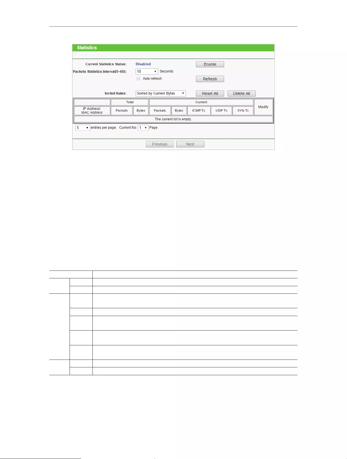
71
Chapter 4 Congure
• Current Statistics Status — Enable or Disable. The default value is disabled. To enable,
click the Enable button. If disabled, the function of DoS protection in Security settings
will disabled.
• Packets Statistics Interval (5-60) — The default value is 10. Select a value between 5 and
60 in the drop-down list. The Packets Statistic Interval indicates the time section of
the packets statistic.
• Sorted Rules – Choose how displayed statistics are sorted.
• Select Auto-refresh to refresh automatically. Click Refresh to refresh immediately.
• Click Reset All to reset the values of all the entries to zero.
• Click Delete All to delete all entries in the table.
Statistics Table
IP/MAC Address The IP and MAC address are displayed with related statistics.
Total Packets The total number of packets received and transmitted by the router.
Bytes The total number of bytes received and transmitted by the router.
Current
Packets The total number of packets received and transmitted in the last Packets Statistic interval
seconds.
Bytes The total number of bytes received and transmitted in the last Packets Statistic interval seconds.
ICMP Tx The number of the ICMP packets transmitted to WAN per second at the specified Packets
Statistics interval. It is shown like “current transmitting rate / Max transmitting rate”.
UDP Tx The number of UDP packets transmitted to the WAN per second at the specified Packets
Statistics interval. It is shown like “current transmitting rate / Max transmitting rate”.
TCP
SYN Tx
The number of TCP SYN packets transmitted to the WAN per second at the specified Packets
Statistics interval. It is shown like “current transmitting rate / Max transmitting rate”.
Modify Reset Reset the value of the entry to zero.
Delete Delete the existing entry in the table.
4. 16. Logout
Click Logout at the bottom of the main menu, and you will log out of the web page and
return to the login window.

72
FAQ
Q1. What can I do if I forgot my wireless password?
The default wireless password is printed on the label of the router. If the password has
been altered, please connect your computer to the router using a cable and follow the
steps below:
1. Visit http://tplinkwifi.net, and log in with the username and password you set for the
router.
2. Go to Wireless > Wireless Security to retrieve or reset your wireless password.
Q2. What can I do if I forgot my login password of the web management
page?
The default username and password of the web management page are admin (in
lowercase).
If you have altered the username and password but Password Recovery is disabled:
1. Reset the router to factory default settings: press and hold the Reset button for about
7 seconds and then release;
2. Visit http://tplinkwifi.net, and enter admin (in lowercase) as both username and
password to login.
Note: You’ll need to reconfigure the router to surf the Internet once the router is reset, and please mark down your
new password for future use.
Q3. I cannot log into the router’s web management page, what can I do?
This can happen for a variety of reasons. Please try the methods below to login again.
• Make sure the router connect to the computer correctly and the corresponding LED
indicator(s) light up.
• Make sure the IP address of your computer is configured as Obtain an IP address
automatically and Obtain DNS server address automatically.
3. Make sure you enter the correct IP address to login: http://tplinkwifi.net.
• Check your computer’s settings:
4. Go to Start > Control Panel > Network and Internet, and click View network status
and tasks.
1 ) Click Internet Options on the bottom left.
2 ) Click Connections and select Never dial a connection.
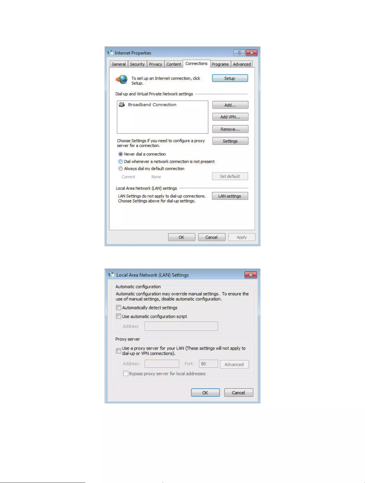
73
3 ) Click LAN settings and deselect the following three options, and click OK.
4 ) Go to Advanced > Restore advanced settings, and click OK to save the settings.

74
• Use another web browser or computer to login again.
• Reset the router to factory default settings and try again. If the login still fails, please
contact the technical support.
Note: You’ll need to reconfigure the router to surf the Internet once the router is reset.
Q4. How to use the WDS Bridging function to extend my wireless
network?
For example, my house covers a large area. The wireless coverage of the router I’m using
(the root router) is limited. I want to use an extended router to extend the wireless
network of the root router.
Note:
• WDS bridging only requires configuration on the extended router.
1. Visit http://tplinkwifi.net, and log into with the username and password you set for
the router.
2. Configure the IP address of the router:
1 ) Go to Network > LAN, configure the IP address of the extended router to
be in the same subnet with the root router; (For example, the IP address of
the root router is 192.168.0.1, the IP address of the extended router can be
192.168.0.2~192.168.0.254. We take 192.168.0.2 as example.)
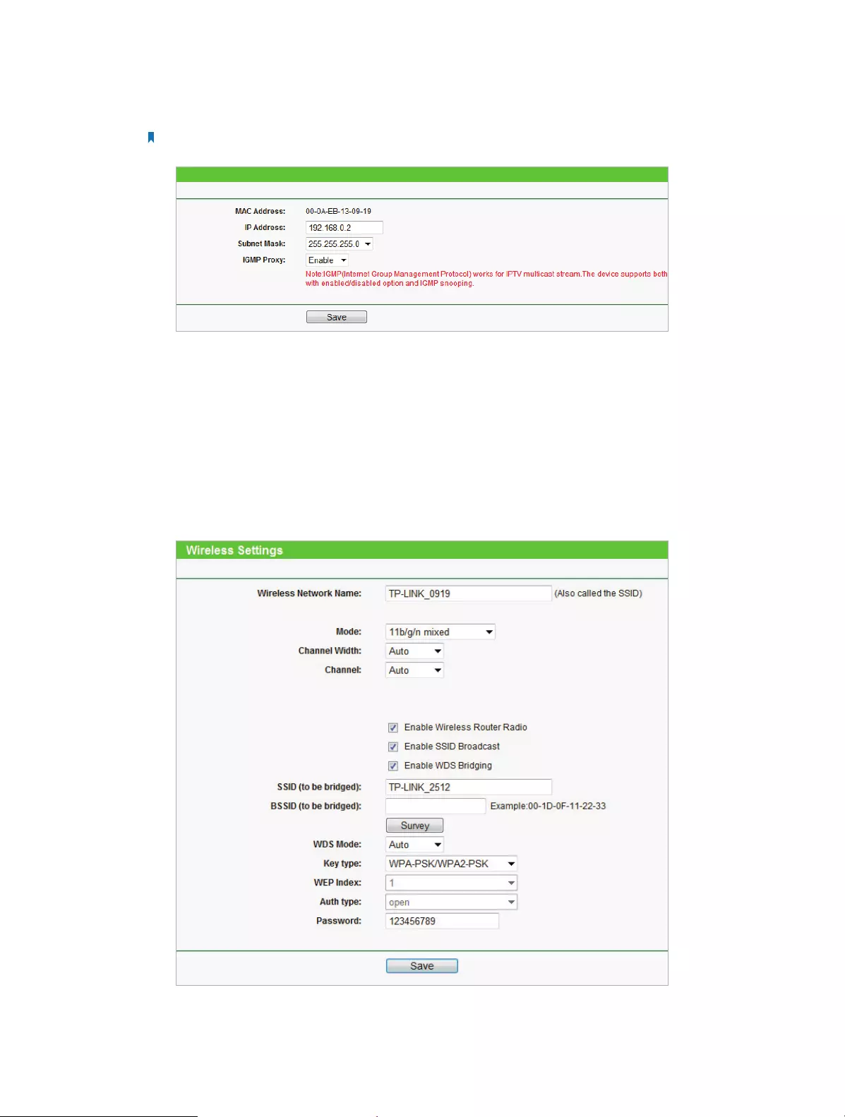
75
2 ) Click Save.
Note: Log into the web management page again if the IP address of the router is altered.
3. Survey the SSID to be bridged:
1 ) Go to Wireless > Wireless Settings and click Enable WDS Bridging.
2 ) Click Survey, locate the root router’s SSID and click Choose (Here we take
TP-LINK_2512 as example).
3 ) If the root router is set with a wireless password, you should enter the wireless
password of the root router.
4 ) Click Save.
4. Disable DHCP:

76
1 ) Go to DHCP, select Disable, and click Save.
Now you can go to Status to check the WDS status. When the WDS status is Run, it
means WDS bridging is successfully built.
Q5. What can I do if I cannot access the Internet even though the
configuration is finished?
1. Visit http://tplinkwifi.net, and log into with the username and password you set for
the router.
2. Go to Advanced > Status to check Internet status:
If IP Address is a valid one, please try the methods below and try again:
• Your computer might not recognize any DNS server addresses, please manually
configure DNS server.
1 ) Go to DHCP.
2 ) Enter 8.8.8.8 as Primary DNS, and click Save.
Tips: 8.8.8.8 is a safe and public DNS server operated by Google.
• Restart the modem and the TP-LINK router.
1 ) Power off your modem and the TP-LINK router, and leave them off for 1 minute.
2 ) Power on your modem first, and wait about 2 minutes.
3 ) Power on the TP-LINK router, and wait another 1 or 2 minutes and check the
Internet access.
• Reset the router to factory default settings and reconfigure the router.
• Upgrade the firmware of the router.
• Check the TCP/IP settings on the particular device if all other devices can get Internet
from the router.
If the IP Address is 0.0.0.0, please try the methods below and try again:

77
• Make sure the physical connection between the router and the modem is proper.
• Clone the MAC address of your computer.
4 ) Visit http://tplinkwifi.net, and log in with the username and password you set
for the router.
5 ) Go to Network > MAC Clone, and select Clone MAC Address.
Tips:
• Some ISP will register the MAC address of your computer when you access the Internet for the first time
through their Cable modem, if you add a router into your network to share your Internet connection, the
ISP will not accept it as the MAC address is changed, so we need to clone your computer’s MAC address to
the router.
• The MAC addresses of a computer in wired connection and wireless connection are different.
• Modify the LAN IP address of the router.
Note:
Most TP-LINK routers use 192.168.0.1/192.168.1.1 as their default LAN IP address, it may conflict with the IP
range of your existent ADSL modem/router. If so, the router is not able to communicate with your modem
and cause you can’t access the Internet. To resolve this problem, we need to change the LAN IP address of the
router to avoid such conflict, for example, 192.168.2.1.
1 ) Visit http://tplinkwifi.net, and log in with the username and password you set
for the router.
2 ) Go to Network > LAN.
3 ) Modify the LAN IP address as the follow picture shows. Here we take 192.168.2.1
as an example.
4 ) Click Save.
• Restart the modem and the TP-LINK router.
1 ) Power off your modem and the TP-LINK router, and leave them off for 1 minute.
2 ) Power on your modem first, and wait about 2 minutes.
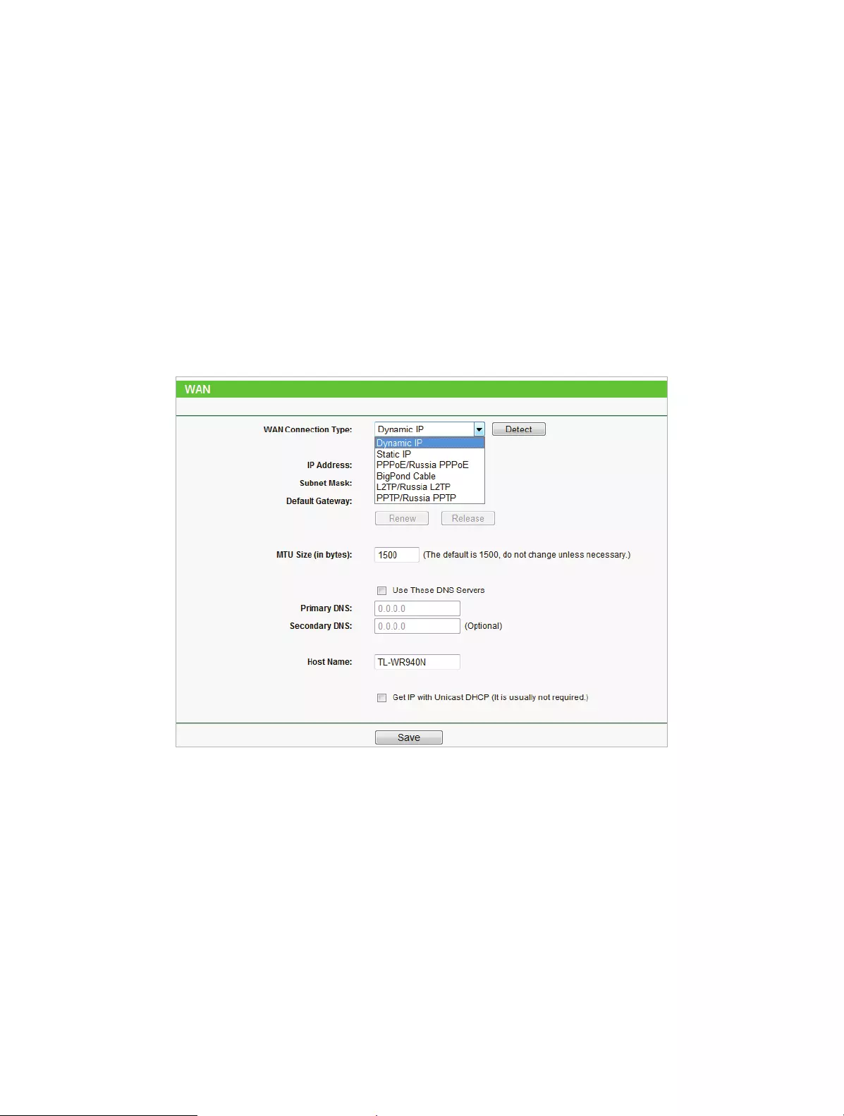
78
3 ) Power on the TP-LINK router, and wait another 1 or 2 minutes and check the
Internet access.
• Double check the Internet Connection Type.
1 ) Confirm your Internet Connection Type, which can be learned from the ISP.
2 ) Visit http://tplinkwifi.net, and log in with the username and password you set
for the router.
3 ) Go to Network > WAN.
4 ) Select your WAN Connection Type and fill in other parameters with the help of
page tips.
5 ) Click Save.
6 ) Restart the modem and the TP-LINK router.
• Please upgrade the firmware of the router.
If you’ve tried every method above but cannot access the Internet, please contact the
technical support.
Q6. What can I do if I cannot find my wireless network or I cannot connect
the wireless network?
If you fail to find any wireless network, please follow the steps below:
• Make sure the wireless function of your device is enabled if you’re using a laptop
with a built-in wireless adapter. You can refer to the relevant document or contact the
laptop manufacturer.

79
• Make sure the wireless adapter driver is installed successfully and the wireless adapter
is enabled.
• On Windows 7
1 ) If you see the message No connections are available, it is usually because the
wireless function is disabled or blocked somehow.
2 ) Clicking Troubleshoot and windows might be able to fix the problem by itself.
• On Windows XP
1 ) If you see the message Windows cannot configure this wireless connection, this
is usually because windows configuration utility is disabled or you are running
another wireless configuration tool to connect the wireless.
2 ) Exit the wireless configuration tool (the TP-LINK Utility, for example).
3 ) Select and right click My Computer on Desktop, and select Manage to open
Computer Management window.
4 ) Expand Services and Applications > Services, and find and locate Wireless Zero
Configuration in the Services list on the right side.
5 ) Right click Wireless Zero Configuration, and then select Properties.
6 ) Change Startup type to Automatic, click Start and make sure the Service status
is Started. And then click OK.
If you can find other wireless network except your own, please follow the steps
below:
• Check the WLAN LED indicator on your wireless router/modem.
• Make sure your computer/device is still in the range of your router/modem. Move
closer if it is currently too far away.
If you can find your wireless network but fail to connect, please follow the steps
below:
• Authenticating problem/password mismatch:
1 ) Sometimes you will be asked to type in a PIN number when you connect to
the wireless network for the first time. This PIN number is different from the
Wireless Password/Network Security Key. Usually you can only find it on the
label of your router.
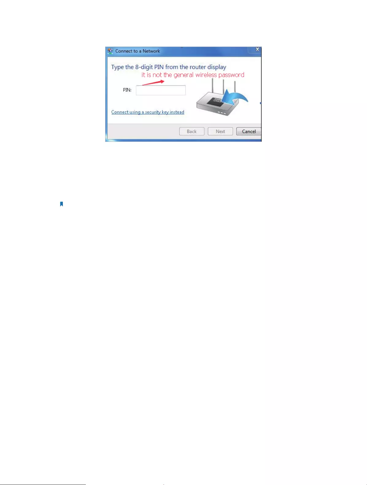
80
2 ) If you cannot find the PIN or PIN failed, you may choose Connecting using a
security key instead, and then type in the Wireless Password/Network Security
Key.
3 ) If it continues to show note of Network Security Key Mismatch, it is suggested
to confirm the wireless password of your wireless router.
Note: Wireless Password/Network Security Key is case sensitive.
• Windows unable to connect to XXXX / Can not join this network / Taking longer
than usual to connect to this network:
• Check the wireless signal strength of your network, if it is weak (1~3 bars),
please move the router closer and try again.
• Change the wireless Channel of the router to 1,6,or 11 to reduce interference
from other networks.
• Re-install or update the driver for your wireless adapter of the computer.

81
COPYRIGHT & TRADEMARKS
Specifications are subject to change without notice. is a registered trademark
of TP-LINK TECHNOLOGIES CO., LTD. Other brands and product names are trademarks
or registered trademarks of their respective holders.
No part of the specifications may be reproduced in any form or by any means or
used to make any derivative such as translation, transformation, or adaptation
without permission from TP-LINK TECHNOLOGIES CO., LTD. Copyright © 2016 TP-LINK
TECHNOLOGIES CO., LTD. All rights reserved.

82
FCC STATEMENT
This equipment has been tested and found to comply with the limits for a Class B
digital device, pursuant to part 15 of the FCC Rules. These limits are designed to provide
reasonable protection against harmful interference in a residential installation. This
equipment generates, uses and can radiate radio frequency energy and, if not installed
and used in accordance with the instructions, may cause harmful interference to radio
communications. However, there is no guarantee that interference will not occur in a
particular installation. If this equipment does cause harmful interference to radio or
television reception, which can be determined by turning the equipment off and on,
the user is encouraged to try to correct the interference by one or more of the following
measures:
• Reorient or relocate the receiving antenna.
• Increase the separation between the equipment and receiver.
• Connect the equipment into an outlet on a circuit different from that to which the
receiver is connected.
• Consult the dealer or an experienced radio/ TV technician for help.
This device complies with part 15 of the FCC Rules. Operation is subject to the following
two conditions:
1. This device may not cause harmful interference.
2. This device must accept any interference received, including interference that may
cause undesired operation.
Any changes or modifications not expressly approved by the party responsible for
compliance could void the user’s authority to operate the equipment.
Note: The manufacturer is not responsible for any radio or TV interference caused by
unauthorized modifications to this equipment. Such modifications could void the
user’s authority to operate the equipment.
FCC RF Radiation Exposure Statement
This equipment complies with FCC RF radiation exposure limits set forth for an
uncontrolled environment. This device and its antenna must not be co-located or
operating in conjunction with any other antenna or transmitter.
“To comply with FCC RF exposure compliance requirements, this grant is applicable to
only Mobile Configurations. The antennas used for this transmitter must be installed to
provide a separation distance of at least 20 cm from all persons and must not be co—
located or operating in conjunction with any other antenna or transmitter.”

83
CE Mark Warning
This is a class B product. In a domestic environment, this product may cause radio
interference, in which case the user may be required to take adequate measures.
RF Exposure Information
This device meets the EU requirements (1999/5/EC Article 3.1a) on the limitation of
exposure of the general public to electromagnetic fields by way of health protection.
The device complies with RF specifications when the device used at 20 cm from your
body.
Canadian Compliance Statement
This device complies with Industry Canada license-exempt RSS standard(s). Operation
is subject to the following two conditions:
1. This device may not cause interference, and
2. This device must accept any interference, including interference that may cause
undesired operation of the device.
Cet appareil est conforme aux norms CNR exemptes de licence d’Industrie Canada. Le
fonctionnement est soumis aux deux conditions suivantes:
1. cet appareil ne doit pas provoquer d’interférences et
2. cet appareil doit accepter toute interférence, y compris celles susceptibles de
provoquer un fonctionnement non souhaité de l’appareil.
Radiation Exposure Statement:
This equipment complies with IC radiation exposure limits set forth for an uncontrolled
environment. This equipment should be installed and operated with minimum distance
20cm between the radiator & your body.
Déclaration d’exposition aux radiations:
Cet équipement est conforme aux limites d’exposition aux rayonnements IC établies
pour un environnement non contrôlé. Cet équipement doit être installé et utilisé avec
un minimum de 20 cm de distance entre la source de rayonnement et votre corps.
Industry Canada Statement
CAN ICES-3 (B)/NMB-3(B)
Korea Warning Statements:
당해 무선설비는 운용중 전파혼신 가능성이 있음.

84
NCC Notice & BSMI Notice:
注意!
依據 低功率電波輻射性電機管理辦法
第十二條 經型式認證合格之低功率射頻電機,非經許可,公司、商號或使用者均
不得擅自變更頻率、加大功率或變更原設計之特性或功能。
第十四條 低功率射頻電機之使用不得影響飛航安全及干擾合法通行;經發現有干
擾現象時,應立即停用,並改善至無干擾時方得繼續使用。前項合法通信,指依
電信規定作業之無線電信。低功率射頻電機需忍受合法通信或工業、科學以及醫
療用電波輻射性電機設備之干擾。
安全諮詢及注意事項
• 請使用原裝電源供應器或只能按照本產品注明的電源類型使用本產品。
• 清潔本產品之前請先拔掉電源線。請勿使用液體、噴霧清潔劑或濕布進行
清潔。
• 注意防潮,請勿將水或其他液體潑灑到本產品上。
• 插槽與開口供通風使用,以確保本產品的操作可靠並防止過熱,請勿堵塞
或覆蓋開口。
• 請勿將本產品置放於靠近熱源的地方。除非有正常的通風,否則不可放在
密閉位置中。
• 請不要私自打開機殼,不要嘗試自行維修本產品,請由授權的專業人士進
行此項工作。
Продукт сертифіковано згідно с правилами системи УкрСЕПРО на відповідність
вимогам нормативних документів та вимогам, що передбачені чинними
законодавчими актами України.
Safety Information
• When product has power button, the power button is one of the way to shut off the
product; when there is no power button, the only way to completely shut off power
is to disconnect the product or the power adapter from the power source.
• Don’t disassemble the product, or make repairs yourself. You run the risk of electric
shock and voiding the limited warranty. If you need service, please contact us.
• Avoid water and wet locations.

85
• Adapter shall be installed near the equipment and shall be easily accessible.
• The plug considered as disconnect device of adapter.
• Use only power supplies which are provided by manufacturer and in the original
packing of this product. If you have any questions, please don’t hesitate to contact us.
Explanations of the symbols on the product label
Symbol Explanation
DC voltage
RECYCLING
This product bears the selective sorting symbol for Waste electrical and electronic equipment
(WEEE). This means that this product must be handled pursuant to European directive 2012/19/
EU in order to be recycled or dismantled to minimize its impact on the environment.
User has the choice to give his product to a competent recycling organization or to the retailer
when he buys a new electrical or electronic equipment.