
Комментарии
11
Войдите или зарегистрируйтесь, чтобы писать комментарии, задавать вопросы и участвовать в обсуждении.
Отличная книга. Когда купил Ланс в 2008 году, очень выручала. Сейчас лежит такая книга, почти новая,  а суть внутрянка та же, что у asx, что у других машин. Полезная книга на все времена.
Спасибо! Удачи в делах и на дороге!
Спасибо, бро! Чтоб дороги у тебя всегда были ровные и баки полные!
От души! И тебе того же 😉
спасибо, а на гугл нет возможности залить? на укр хлопатно скачать
🙏
ох спс тебе! я как раз свою посеял.
Mitsubishi Lancer X: Руководства по эксплуатации
Материал из MMC Manuals
Перейти к навигации
Перейти к поиску
Руководства по эксплуатации Mitsubishi Lancer X. Брошюры, каталоги, спецификации, карты технического обслуживания.
↑ Mitsubishi Lancer X
| Язык/Language: | Русский • English |
|---|
Брошюры, каталоги, спецификации
Руководства по эксплуатации
- Руководство по эксплуатации Mitsubishi Lancer MY 2008 (Россия), рус., постранично || одним файлом, pdf, 58,2 МБ
- Руководство по эксплуатации Mitsubishi Lancer MY 2014 (Россия), pdf, рус., 28,8 МБ
- Руководство по эксплуатации Mitsubishi Lancer MY 2015 (Россия), pdf, рус., 22,5 МБ
- Руководство по эксплуатации Mitsubishi Lancer и Mitsubishi Lancer Ralliart (Россия), pdf, рус., 56,9 МБ
- Краткое руководство Mitsubishi Lancer MY 2011 (North America), pdf, eng., 1,57 МБ
- Краткое руководство Mitsubishi Lancer MY 2012 (North America), pdf, eng., 1,73 МБ
- Краткое руководство Mitsubishi Lancer MY 2014 (North America), pdf, eng., 892 кБ
- Краткое руководство Mitsubishi Lancer MY 2015 (North America), pdf, eng., 1,26 МБ
- Краткое руководство Mitsubishi Lancer MY 2016 (North America), pdf, eng., 9,76 МБ
- Краткое руководство Mitsubishi Lancer MY 2017 (North America), pdf, eng., 11,1 МБ
- Быстрое знакомство с Mitsubishi Lancer, pdf, eng., 948 кБ
- Руководство по эксплуатации Mitsubishi Lancer MY 2011 (Europe), pdf, eng., 19,1 МБ
- Руководство по эксплуатации Mitsubishi Lancer MY 2012 (Europe), pdf, eng., 22,9 МБ
- Руководство по эксплуатации Mitsubishi Lancer Sportback MY 2011 (Europe), pdf, eng., 20,4 МБ
- Руководство по эксплуатации Mitsubishi Lancer Sportback MY 2012 (Europe), pdf, eng., 21,8 МБ
- Руководство по эксплуатации Mitsubishi Lancer MY 2010 (North America), pdf, eng., 25,1 МБ
- Руководство по эксплуатации Mitsubishi Lancer MY 2011 (North America), pdf, eng., 42,3 МБ
- Руководство по эксплуатации Mitsubishi Lancer MY 2012 (North America), pdf, eng., 22,3 МБ
- Руководство по эксплуатации Mitsubishi Lancer MY 2013 (North America), pdf, eng., 23,8 МБ
- Руководство по эксплуатации Mitsubishi Lancer MY 2014 (North America), pdf, eng., 57,5 МБ
- Руководство по эксплуатации Mitsubishi Lancer MY 2015 (North America), pdf, eng., 16,6 МБ
- Руководство по эксплуатации Mitsubishi Lancer MY 2016 (North America), pdf, eng., 13,1 МБ
- Руководство по эксплуатации Mitsubishi Lancer MY 2017 (North America), pdf, eng., 14,3 МБ
- Руководство по эксплуатации Mitsubishi Lancer Sportback MY 2010 (North America), pdf, eng., 20,6 МБ
- Руководство по эксплуатации Mitsubishi Lancer Sportback MY 2011 (North America), pdf, eng., 22,2 МБ
- Руководство по эксплуатации Mitsubishi Lancer Sportback MY 2012 (North America), pdf, eng., 22,1 МБ
- Руководство по эксплуатации Mitsubishi Lancer Sportback MY 2013 (North America), pdf, eng., 22,0 МБ
- Руководство по эксплуатации Mitsubishi Lancer Sportback MY 2014 (North America), pdf, eng., 55,1 МБ
Руководства по эксплуатации аудио-системы
- См. раздел Аудиооборудование: Руководства по эксплуатации
Карты технического обслуживания
- Периодическое техническое обслуживание (карта ТО), pdf, 301 кБ
- Периодическое техническое обслуживание при тяжелых условиях эксплуатации, pdf, 392 кБ
- Перечень запчастей и расходников для технического обслуживания Lancer X
Разное
- Активация противотуманных фар без специального оборудования
Руководство на английском языке по кузовному ремонту автомобилей Mitsubishi Lancer/Lancer Station Wagon 1993 года выпуска.
- Автор: —
- Издательство: Mitsubishi Motors Corp.
- Год издания: 1992
- Страниц: —
- Формат: PDF
- Размер: 25,2 Mb
- Автор: —
- Издательство: Mitsubishi Motors Corp.
- Год издания: 1993-2000
- Страниц: —
- Формат: PDF
- Размер: 33,9 Mb
Сборник схем на английском языке электрооборудования автомобиля Mitsubishi Lancer 1997-2000 годов выпуска.
- Автор: —
- Издательство: Mitsubishi Motors Corp.
- Год издания: 1996-1999
- Страниц: —
- Формат: PDF
- Размер: 5,3 Mb
Сборник схем на английском языке электрооборудования автомобиля Mitsubishi Lancer 2007 года выпуска.
- Автор: —
- Издательство: Mitsubishi Motors Corp.
- Год издания: —
- Страниц: —
- Формат: PDF
- Размер: 99,3 Mb
Мультимедийное руководство на английском языке по техническому обслуживанию и ремонту автомобилей Mitsubishi Lancer/Lancer SportBack/Lancer Evolution 2004 года выпуска.
- Автор: —
- Издательство: Mitsubishi Motors
- Год издания: 2003
- Страниц: —
- Формат: —
- Размер: 191,5 Mb
Сборник руководств на английском языке по техническому обслуживанию и ремонту автомобилей Mitsubishi Colt и Mitsubishi Lancer 1992-1996 годов выпуска.
- Автор: —
- Издательство: Mitsubishi Motors Corp.
- Год издания: —
- Страниц: —
- Формат: PDF
- Размер: 41,2 Mb
Сборник руководств на английском языке по техническому обслуживанию и ремонту автомобилей Mitsubishi Colt и Mitsubishi Lancer 1996-2001 годов выпуска.
- Автор: —
- Издательство: Mitsubishi Motors Corp.
- Год издания: 1995-2000
- Страниц: —
- Формат: PDF
- Размер: 26,5 Mb
Руководство на английском языке по техническому обслуживанию и ремонту автомобилей Mitsubishi Lancer/Lancer Wagon 2005 года выпуска. .
- Автор: —
- Издательство: Mitsubishi Motors Corp.
- Год издания: 2004
- Страниц: —
- Формат: PDF
- Размер: 46,3 Mb
Сборник руководств на английском языке по техническому обслуживанию и ремонту автомобиля Mitsubishi Lancer 2006 года выпуска.
- Автор: —
- Издательство: Mitsubishi Motors Corp.
- Год издания: —
- Страниц: —
- Формат: PDF
- Размер: 66,2 Mb
Сборник мультимедийных руководств на английском языке по техническому обслуживанию и ремонту автомобилей Mitsubishi Lancer/Lancer Sportback 2009-2011 годов выпуска
- Автор: —
- Издательство: Mitsubishi Motors
- Год издания: —
- Страниц: —
- Формат: —
- Размер: 4,0 Gb
уководство на английском языке по техническому обслуживанию и ремонту автомобиля Mitsubishi Lancer 2012 года выпуска.
- Автор: —
- Издательство: Mitsubishi Motors Corp.
- Год издания: —
- Страниц: 1253
- Формат: PDF
- Размер: 40,6 Mb
Руководство на английском языке по техническому обслуживанию и ремонту автомобиля Mitsubishi Lancer серий CE/CG. .
- Автор: —
- Издательство: Mitsubishi Motors Corp.
- Год издания: 2001-2002
- Страниц: —
- Формат: PDF
- Размер: 61,5 Mb
Руководство на английском и испанском языках по техническому обслуживанию и ремонту (включая руководство по кузовному ремонту) автомобиля Mitsubishi Lancer 2004 года выпуска.
- Автор: —
- Издательство: Mitsubishi Motors Corp.
- Год издания: 2003
- Страниц: —
- Формат: PDF
- Размер: 418,6 Mb
Руководство по ремонту автомобилей Mitsubishi Colt и Mitsubishi Lancer 1991-1995 годов выпуска с бензиновыми и дизельными двигателями.
- Автор: —
- Издательство: СверчокЪ
- Год издания: 2005
- Страниц: 279
- Формат: PDF
- Размер: 38,2 Mb
Руководство по ремонту автомобилей Mitsubishi Colt и Mitsubishi Lancer 1991-2004 годов выпуска с бензиновыми и дизельными двигателями
- Автор: В. Покрышкин
- Издательство: СверчокЪ
- Год издания: 2005
- Страниц: 279
- Формат: DjVu
- Размер: 19,9 Mb
Руководство по эксплуатации, техническому обслуживанию и ремонту автомобиля Mitsubishi Lancer 2001-2007 годов выпуска с бензиновыми двигателями объемом 1,3/1,6/2,0 л.
- Автор: —
- Издательство: Третий Рим
- Год издания: —
- Страниц: 304
- Формат: PDF
- Размер: 165,2 Mb
Мультимедийное руководство по эксплуатации и ремонту автомобилей Mitsubishi Colt/Lancer/Mirage/Cordia/Tredia/Precis 1983-1993 годов выпуска.
- Автор: —
- Издательство: —
- Год издания: —
- Страниц: —
- Формат: ISO
- Размер: 196,8 Mb
Сборник руководств по техническому обслуживанию и ремонту автомобиля Mitsubishi Lancer 2008 года выпуска.
- Автор: —
- Издательство: Mitsubishi Motors Corp.
- Год издания: 2007
- Страниц: —
- Формат: PDF
- Размер: 186,7 Mb
Сборник руководств по техническому обслуживанию и ремонту автомобилей Mitsubishi Colt и Mitsubishi Lancer 1996-2001 годов выпуска.
- Автор: —
- Издательство: Mitsubishi Motors Corp.
- Год издания: 1995-2000
- Страниц: —
- Формат: PDF
- Размер: 54,0 Mb
Руководство по техническому обслуживанию и ремонту автомобилей Mitsubishi Lancer/Lancer Wagon 2005 года выпуска.
- Автор: —
- Издательство: Mitsubishi Motors Corp.
- Год издания: 2004
- Страниц: —
- Формат: PDF
- Размер: 159,7 Mb
Руководство по эксплуатации, техническому обслуживанию и ремонту автомобилей Mitsubishi Colt/Lancer/Mirage 1991-1996 и Mitsubishi Libero 1992-2002 годов выпуска с бензиновыми и дизельными двигателями.
- Автор: —
- Издательство: Легион-Автодата
- Год издания: —
- Страниц: 448
- Формат: —
- Размер: —
Руководство по эксплуатации, техническому обслуживанию и ремонту автомобиля Mitsubishi Lancer X 2006-2016 годов выпуска с бензиновыми двигателями.
- Автор: —
- Издательство: Легион-Автодата
- Год издания: —
- Страниц: 500
- Формат: —
- Размер: —
Руководство по эксплуатации и ремонту автомобиля Mitsubishi Lancer Cedia 2000-2003 года выпуска.
- Автор: —
- Издательство: Монолит
- Год издания: —
- Страниц: 567
- Формат: PDF
- Размер: 47,0 Mb
уководство по эксплуатации и ремонту автомобилей Mitsubishi Lancer X и Mitsubishi Galant Fortis с 2006 года выпуска с бензиновыми и дизельными двигателями.
- Автор: —
- Издательство: Монолит
- Год издания: —
- Страниц: 384
- Формат: —
- Размер: —
Руководство по эксплуатации и ремонту автомобилей Mitsubishi Colt и Mitsubishi Lancer/Lancer Wagon с 1992 года выпуска с бензиновыми и дизельными двигателями.
- Автор: —
- Издательство: Монолит
- Год издания: —
- Страниц: 326
- Формат: —
- Размер: —
Руководство по эксплуатации, техническому обслуживанию и ремонту автомобилей Mitsubishi Colt/Lancer/Mirage/Cordia/Tredia/Precis/Galant/Sigma/Eterna/Magna/Sapporo 1983-1993 годов выпуска с бензиновыми и дизельными двигателями.
- Автор: —
- Издательство: Техно-BOOK
- Год издания: 2005
- Страниц: 273
- Формат: PDF
- Размер: 34,7 Mb
Руководство по эксплуатации и техническому обслуживанию автомобиля Mitsubishi Lancer 2008 года выпуска.
- Автор: —
- Издательство: Mitsubishi Motors Corp.
- Год издания: 2007
- Страниц: 487
- Формат: PDF
- Размер: 48,9 Mb
Руководство по эксплуатации, техническому обслуживанию и ремонту автомобилей Mitsubishi Lancer/Lancer Wagon с 2003 года выпуска с бензиновыми двигателями объемом 1,3/1,6/2,0 л
- Автор: —
- Издательство: Арго-Авто
- Год издания: —
- Страниц: 406
- Формат: —
- Размер: —
Руководство по эксплуатации, техническому обслуживанию и ремонту автомобиля Mitsubishi Lancer с 2007 года выпуска с бензиновыми двигателями объемом 1,5/1,8/2,0 л.
- Автор: —
- Издательство: Арго-Авто
- Год издания: —
- Страниц: 600
- Формат: —
- Размер: —
Руководство по эксплуатации, техническому обслуживанию и ремонту автомобилей Mitsubishi Colt и Mitsubishi Lancer 1993-2003 годов выпуска с бензиновыми и дизельными двигателями.
- Автор: —
- Издательство: Автомастер
- Год издания: 2003
- Страниц: 281
- Формат: PDF
- Размер: 16,4 Mb
Руководство по эксплуатации, техническому обслуживанию и ремонту автомобиля Mitsubishi Lancer 2003-2010 годов выпуска с бензиновыми двигателями объемом 1,3/1,6 л.
- Автор: —
- Издательство: Автонавигатор
- Год издания: —
- Страниц: 304
- Формат: —
- Размер: —
Руководство по техническому обслуживанию и ремонту автомобилей Mitsubishi Mirage/Lancer/Colt/Galant/Eterna/Sapporo/Sigma/Cordia/Tredia/Precis 1983-1993 годов выпуска.
- Автор: —
- Издательство: MoToR
- Год издания: 1996
- Страниц: 183
- Формат: —
- Размер: —
Руководство по техническому обслуживанию и ремонту автомобилей Mitsubishi Colt и Mitsubishi Lancer 1984-1992 годов выпуска.
- Автор: Г.Р. Этцольд
- Издательство: Arinas
- Год издания: 1994
- Страниц: 339
- Формат: DjVu
- Размер: 10,4 Mb
Руководство по техническому обслуживанию и ремонту автомобиля Mitsubishi Lancer с правым рулем 2003-2007 годов выпуска с бензиновыми двигателями объемом 1,5/1,8 л.
- Автор: —
- Издательство: Легион-Автодата
- Год издания: —
- Страниц: 544
- Формат: —
- Размер: —
Руководство по техническому обслуживанию и ремонту автомобиля Mitsubishi Lancer Cedia 2000-2003 годов выпуска с бензиновыми двигателями объемом 1,5/1,8 л.
- Автор: —
- Издательство: Легион-Автодата
- Год издания: —
- Страниц: 584
- Формат: —
- Размер: —
-
ysh
- Любопытный Лансеровод
- Сообщения: 108
- Зарегистрирован: Вс май 04, 2008 8:21 am
- Город: Надым
- Зодиак:
#2
Непрочитанное сообщение
ysh » Вт май 20, 2008 11:56 am
Руководство по эксплуатации Mitsubishi Lancer X одним файлом.
http://kingly.ifolder.ru/6639933
Мой авто: LancerX (2008) CVT 2.0 (150л.с.) Invite+ (S25) «Серый мика» (Р) А39
-
soudakov
- Начинающий Лансеровод
- Сообщения: 11
- Зарегистрирован: Вт окт 21, 2008 1:18 pm
-
Alexey56
- Вероятный Лансеровод
- Сообщения: 3
- Зарегистрирован: Пн май 28, 2012 8:42 pm
- Зодиак:
#7
Непрочитанное сообщение
Alexey56 » Сб июн 02, 2012 9:13 am
Подскажите где можно скачать руководство по ремонту двигатель 4А91 1.5?
GROUP INDEX
LANCER /
LANCER WAGON
WORKSHOP MANUAL
FOREWORD
This Workshop manual contains procedures for
service mechanics, including removal, disassembly,
inspection, adjustment, reassembly and installation.
Use the following manuals in combination with this
manual as required.
General . . . . . . . . . . . . . . . . . . . . . . . .
Engine. . . . . . . . . . . . . . . . . . . . . . . . .
Engine Lubrication . . . . . . . . . . . . . .
Fuel . . . . . . . . . . . . . . . . . . . . . . . . . . .
Engine Cooling . . . . . . . . . . . . . . . . .
Intake and Exhaust . . . . . . . . . . . . . .
Engine Electrical . . . . . . . . . . . . . . . .
Engine and Emission Control . . . . .
Clutch . . . . . . . . . . . . . . . . . . . . . . . . .
Manual Transmission . . . . . . . . . . . .
Automatic Transmission. . . . . . . . . .
Front Axle. . . . . . . . . . . . . . . . . . . . . .
00
11
12
13
14
15
16
17
21
22
23
26
TECHNICAL INFORMATION MANUAL
PYME0302
PYME0302-A
WORKSHOP MANUAL
CHASSIS GROUP PWME0302
BODY REPAIR MANUAL
PBME0302
PBME0302-A
PARTS CATALOGUE
B606K005A_
All information, illustrations and product descriptions
contained in this manual are current as at the time of
publication. We, however, reserve the right to make
changes at any time without prior notice or obligation.
Rear Axle . . . . . . . . . . . . . . . . . . . . . .
Wheel and Tyre . . . . . . . . . . . . . . . . .
Power Plant Mount . . . . . . . . . . . . . .
Front Suspension . . . . . . . . . . . . . . .
Rear Suspension . . . . . . . . . . . . . . . .
Service Brakes. . . . . . . . . . . . . . . . . .
Parking Brakes . . . . . . . . . . . . . . . . .
Power Steering . . . . . . . . . . . . . . . . .
Body . . . . . . . . . . . . . . . . . . . . . . . . . .
Exterior . . . . . . . . . . . . . . . . . . . . . . . .
Interior and Supplemental
. . . . . . . . . .
Restraint System (SRS)
Chassis Electrical . . . . . . . . . . . . . . .
Heater, Air Conditioner and
. . . . . . .
Ventilation
Component Locations. . . . . . . . . . . .
27
31
32
33
34
35
36
37
42
51
52
54
55
70
Mitsubishi Motors Corporation May 2004
Configration Diagrams . . . . . . . . . . .
Circuit Diagrams . . . . . . . . . . . . . . . .
80
90

WARNINGS REGARDING SERVICING OF SUPPLEMENTAL
RESTRAINT SYSTEM (SRS) EQUIPPED VEHICLES
(1) Improper service or maintenance of any component of the SRS or any SRS-related component,
can lead to personal injury or death to service personnel (from inadvertent firing of the air bag)
or to the driver and passenger (from rendering the SRS inoperative).
(2) The SRS components and seat belt with pretensioner should not be subjected to heat, so
remove the SRS-ECU, driverís and front passengerís air bag modules, clock spring, side air bag
modules, and seat belt -pre-tensioner before drying or baking the vehicle after painting.
ï SRS-ECU, air bag module and clock spring 93°C or more
ï Seat belt with pre-tensioner: 90°C or more
(3) Service or maintenance of any SRS component or SRS-related component must be performed
only at an authorized MITSUBISHI dealer.
(4) MITSUBISHI dealer personnel must thoroughly review this Manual, and especially its GROUP
52B — Supplemental Restraint System (SRS), before beginning any service or maintenance of
any component of the SRS or any SRS-related component.
NOTE
Section titles with asterisks (*) in the table of contents in each group indicate operations requiring warnings.

GROUP 17
ENGINE AND
EMISSION
CONTROL
CONTENTS
17-1
ENGINE CONTROL. . . . . . . . . .
GENERAL INFORMATION . . . . . . 17-2
SERVICE SPECIFICATIONS. . . . . 17-2
ON-VEHICLE SERVICE. . . . . . . . . 17-2
ACCEL CABLE CHECK AND
ADJUSTMENT. . . . . . . . . . . . . . . . . . . . 17-2
ACCELERATOR CABLE AND
PEDAL . . . . . . . . . . . . . . . . . . . . . .
REMOVAL AND INSTALLATION . . . . . 17-3
17-2
17-3
EMISSION CONTROL MPI . . . . 17-5
GENERAL INFORMATION . . . . . .
EMISSION CONTROL DEVICE
REFERENCE TABLE . . . . . . . . . .
SERVICE SPECIFICATION(S) . . . 17-5
VACUUM HOSE. . . . . . . . . . . . . . . 17-6
VACUUM HOSE PIPING DIAGRAM . . . 17-6
VACUUM CIRCUIT DIAGRAM . . . . . . . 17-7
VACUUM HOSE CHECK. . . . . . . . . . . . 17-8
VACUUM HOSE INSTALLATION . . . . . 17-8
CRANKCASE EMISSION CONTROL
SYSTEM. . . . . . . . . . . . . . . . . . . . .
GENERAL INFORMATION (CRANKCASE
EMISSION CONTROL SYSTEM) . . . . . 17-8
17-5
17-5
17-8
COMPONENT LOCATION (CRANKCASE
EMISSION CONTROL SYSTEM) . . . . . 17-9
POSITIVE CRANKCASE VENTILATION
SYSTEM CHECK . . . . . . . . . . . . . . . . . . 17-9
POSITIVE CRANKCASE VENTILATION
(PCV) VALVE CHECK . . . . . . . . . . . . . . 17-9
EVAPORATIVE EMISSION CONTROL
SYSTEM . . . . . . . . . . . . . . . . . . . . . 17-9
GENERAL INFORMATION (EVAPORATIVE
EMISSION CONTROL SYSTEM) . . . . . 17-9
COMPONENT LOCATION (EVAPORATIVE
EMISSION CONTROL SYSTEM) . . . . . 17-10
PURGE CONTROL SYSTEM CHECK. . 17-10
PURGE PORT VACUUM CHECK . . . . . 17-11
PURGE CONTROL SOLENOID VALVE
CHECK . . . . . . . . . . . . . . . . . . . . . . . . . . 17-11
FUEL VAPOUR CANISTER REMOVAL
AND INSTALLATION . . . . . . . . . . . . . . . 17-12
EXHAUST GAS RECIRCULATION
(EGR) SYSTEM . . . . . . . . . . . . . . .
GENERAL INFORMATION
(EGR SYSTEM) . . . . . . . . . . . . . . . . . . . 17-13
COMPONENT LOCATION
(EGR SYSTEM) . . . . . . . . . . . . . . . . . . . 17-14
EGR SYSTEM CHECK . . . . . . . . . . . . . 17-15
EGR VALVE CHECK . . . . . . . . . . . . . . . 17-15
EGR PORT VACUUM CHECK <4G1>. . 17-16
EGR CONTROL SOLENOID VALVE
CHECK <4G1> . . . . . . . . . . . . . . . . . . . . 17-16
EGR CONTROL SOLENOID VALVE
CHECK <4G6> . . . . . . . . . . . . . . . . . . . . 17-17
EXHAUST GAS RECIRCULATION (EGR)
VALVE REMOVAL AND
INSTALLATION . . . . . . . . . . . . . . . . . . . 17-18
CATALYTIC CONVERTER . . . . . . 17-18
REMOVAL AND INSTALLATION . . . . . . 17-18
17-13
17-2
ENGINE AND EMISSION CONTROL
ENGINE CONTROL
ENGINE CONTROL
GENERAL INFORMATION
M1171000100277
A cable-type accelerator mechanical
suspended-type pedal has been adopted.
SERVICE SPECIFICATIONS
M1171000300088
Item Standard value
Accel cable play mm 1.0 − 2.0
Engine idle speed r/min 4G1 750 ± 50
4G6 750 ± 100
ON-VEHICLE SERVICE
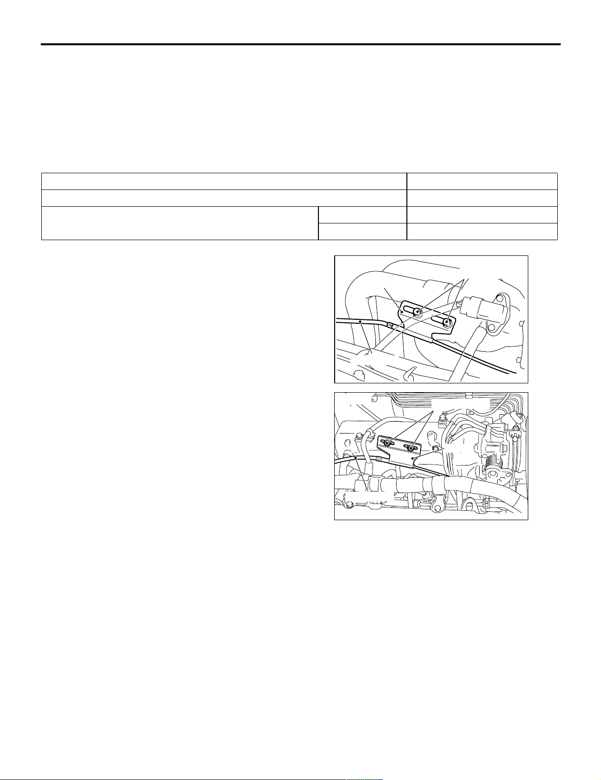
ACCEL CABLE CHECK AND
<4G1>
Adjusting bolts
Plate
ADJUSTMENT
M1171000900314
1. Turn A/C and lights OFF. Inspect and adjust at no
load.
2. Warm engine until stabilized at idle.
3. Confirm idle speed is at standard value.
Standard value:
750 ± 50 r/min <4G1>
750 ± 100 r/min <4G6>
Accel cable
<4G6>
Adjusting bolts
AC207966
AC
4. Stop engine. [ignition switch: LOCK (OFF)
position].
5. Confirm there are no sharp bends in the
accelerator cable.
6. Check the inner cable for correct slack.
Standard value: 1.0 − 2.0 mm
7. If there is too much slack or no slack, adjust play
by the following procedures.
Plate
Accel cable
AC301055
AC
(1) Loosen the adjusting bolts to release the
cable.
(2) Move the plate until the inner cable play is at
the standard value, and then tighten the
adjusting bolts.
(3) After adjusting, check that the throttle lever is
touching the stopper.

ENGINE AND EMISSION CONTROL
ENGINE CONTROL
ACCELERATOR CABLE AND PEDAL
17-3
REMOVAL AND INSTALLATION
Post-installation Operation
Adjusting the Accelerator Cable (Refer to P.17-2).
<L.H. drive vehicles>
3
M1171001200341
2
5.0 ± 1.0 N·m
12 ± 2 N·m
10
1
7
9
7
N
5
4
<R.H. drive vehicles>
5.0 ± 1.0 N·m
2
Accelerator cable assembly
removal steps
1. Inner cable connection (Accelerator
pedal side)
2. Inner cable connection (Throttle body
side)
3. Accelerator cable assembly
8
13
N
12
6
Y1060AU
11
3
1
12 ± 2 N·m
9
7
13
11
12
6
N
Y1059AU
AC304070
AB
10
N
5
4
7
8
Accelerator pedal assembly
removal steps
1. Inner cable connection (Accelerator
pedal side)
4. Accelerator pedal assembly
5. Accelerator control equip nut
6. Accelerator pedal arm and
accelerator pedal pad assembly
17-4
ENGINE AND EMISSION CONTROL
ENGINE CONTROL
Accelerator pedal assembly
removal steps (Continued)
7. Accelerator control equip bushing
8. Accelerator pedal arm return spring
9. Accelerator pedal arm stopper
INSTALLATION SERVICE POINT
>>A<< ACCEL PEDAL PAD
INSTALLATION
CAUTION
To p reve nt damag es to the ac c eler ator pe dal pad,
warm the thumb area of the accelerator pedal
pad with a dryer, etc. prior to assembling it.
NOTE: If it is difficult to assemble, apply soapy water
to the thumb area to enhance the assembling
process.
>>A<<
Accelerator pedal assembly
removal steps (Continued)
10. Accelerator pedal arm bracket
11. Ac c e l erator p edal a rm
12. Accelerator pedal pad
13. Accelerator pedal arm stopper
ENGINE AND EMISSION CONTROL
EMISSION CONTROL <MPI>
EMISSION CONTROL <MPI>
17-5
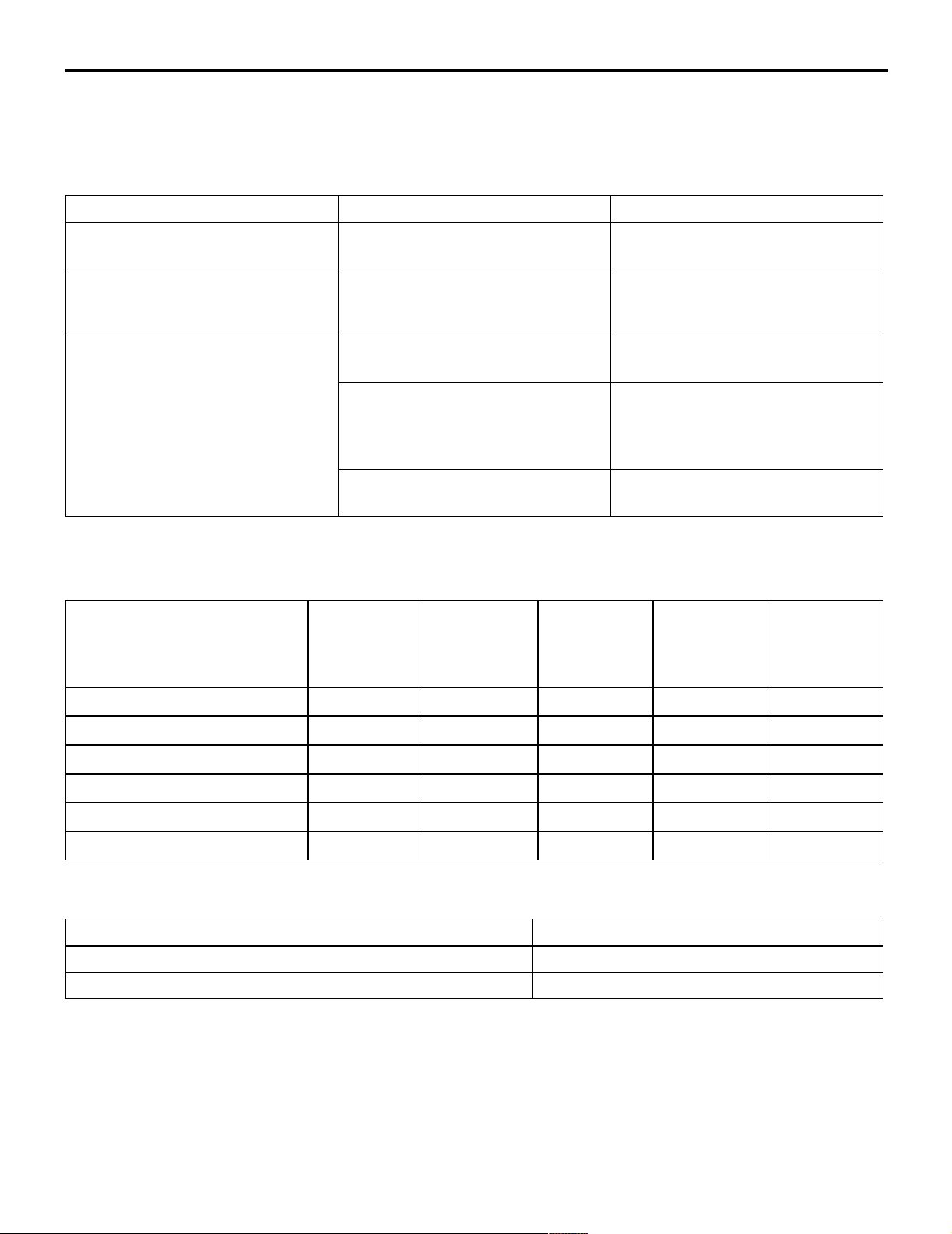
GENERAL INFORMATION
M1173000100370
The emission control system consists of the following
subsystems:
Items Name Specification
Crankcase emission control
system
Evaporative emission control
system
Exhaust emission control system Air-fuel ratio control device — MPI
Positive crankcase ventilation
(PCV) valve
Canister
Purge control solenoid valve
system
Exhaust gas recirculation system
• EGR valve
• EGR control solenoid valve
Catalytic converter Monolith type
• Crankcase emission control system
• Evaporative emission control system
• Exhaust emission control system
Varia b le flo w t yp e
(Purpose: HC reduction)
Equipped
Duty cycle type solenoid valve
(Purpose: HC reduction)
Oxygen sensor feedback type
(Purpose: CO, HC, NOx reduction)
Equipped
Single type
Duty cycle type solenoid valve
(Purpose: NOx reduction)
(Purpose: CO, HC, NOx reduction)
EMISSION CONTROL DEVICE
REFERENCE TABLE
M1173006600135
Related parts Crankcase
emission
control
system
Evaporative
emission
control
system
Air/fuel ratio
control
system
Catalytic
converter
Exhaust gas
recirculation
system
PCV valve
Purge control solenoid valve
MPI system component
Catalytic converter
EGR valve
EGR control solenoid valve
×
×
××
SERVICE SPECIFICATION(S)
M1173000300288
Items Standard value
Purge control solenoid valve coil resistance (at 20°C) Ω 30 − 34
EGR control solenoid valve coil resistance (at 20°C) Ω 29 − 35
×
×
×
17-6
VACUUM HOSE
ENGINE AND EMISSION CONTROL
EMISSION CONTROL <MPI>
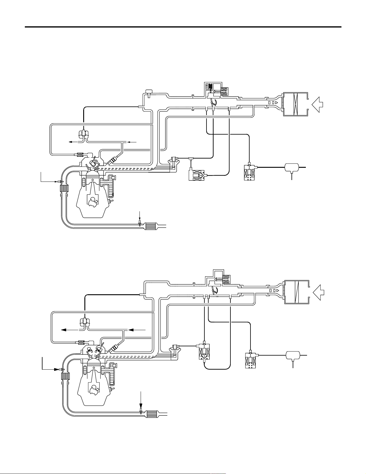
VACUUM HOSE PIPING DIAGRAM
M1173000900417
<4G1>
To
fuel tank
Oxygen sensor
(front)
Catalytic
converter
Fuel pressure
regulator
Oxygen sensor (rear)
From
fuel pump
EGR valve
EGR control
solenoid valve
Air cleaner
Air
Canister
Purge control
solenoid valve
<4G6>
To
fuel tank
Oxygen sensor
(front)
Catalytic
converter
PCV valve
Fuel pressure
regulator
Catalytic
converter
From
fuel pump
EGR valve
Oxygen sensor (rear)
Catalytic
converter
EGR control
solenoid valve
Purge control
solenoid valve
Air cleaner
Canister
AK300964
AB
Air
AK204364
AC
ENGINE AND EMISSION CONTROL
EMISSION CONTROL <MPI>
17-7
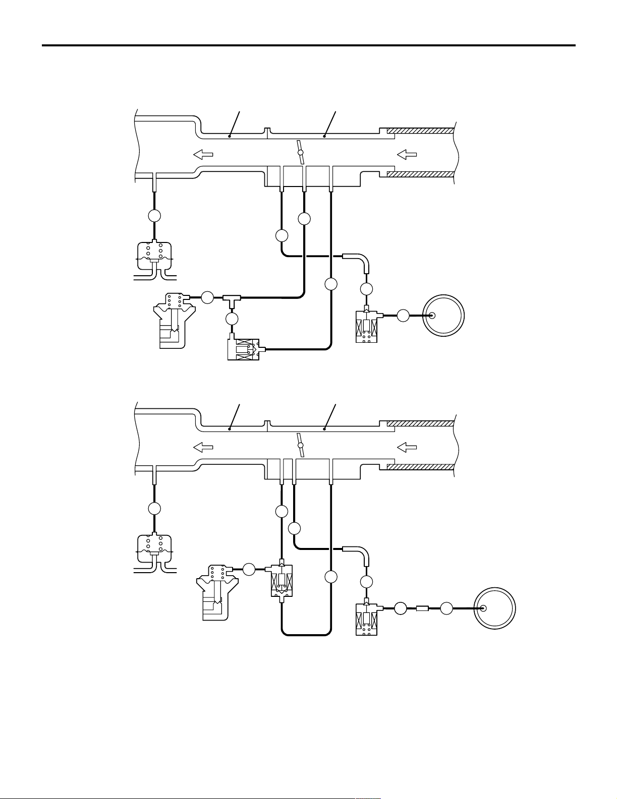
VACUUM CIRC UIT DIA GRAM
<4G1>
To
combustion
chamber
L
Fuel
pressure
regulator
Vacuum hose colour
B: Black
G: Green
R: Red
Y: Yellow
L: Blue
EGR
valve
G
M1173007100263
Intake manifold
G
EGR
control
solenoid
valve
Throttle body
From
air
cleaner
G
R
Y
R
Purge
control
solenoid
valve
Canister
B
AK300765
AB
<4G6>
To
combustion
chamber
Fuel
pressure
regulator
Vacuum hose colour
B: Black
G: Green
R: Red
W: White
Y: Yellow
L: Blue
Intake manifold
L
G
EGR
control
solenoid
EGR
valve
valve
W
R
Throttle body
Y
B
B
Purge
control
solenoid
valve
From
air
cleaner
Canister
B
AK300766
AB

17-8
ENGINE AND EMISSION CONTROL
EMISSION CONTROL <MPI>
VACUUM HOSE CHECK
M1173007300159
1. Using the piping diagram as a guide, check to be
sure that the vacuum hoses are correctly
connected.
2. Check the connection condition of the vacuum
hoses, (removed, loose, etc.) and check to be
sure that there are no bends or damage.
VACUUM HOSE INSTALLATION
M1173007200107
1. When connecting the vacuum hoses, they should
be securely inserted onto the nipples.
2. Connect the hoses correctly, using the vacuum
hose piping diagram as a guide.
CRANKCASE EMISSION CONTROL
SYSTEM
GENERAL INFORMATION (CRANKCASE
EMISSION CONTROL SYSTEM)
M1173005000237
The crankcase emission control system prevents
blow-by gases from escaping inside the crankcase
into the atmosphere.
Fresh air is sent from the air cleaner into the
crankcase through the breather hose.
The air becomes mixed with the blow-by gases
inside the crankcase.
The blow-by gas inside the crankcase is drawn into
the intake manifold through the positive crankcase
ventilation (PCV) valve.
The PCV valve lifts the plunger according to the
intake manifold vacuum so as to regulate the flow of
blow-by gas properly.
In other words, the blow-by gas flow is regulated
during low load engine operation to maintain engine
stability, while the flow is increased during high load
operation to improve the ventilation performance.
SYSTEM DIAGRAM
Ventilation hose
PCV valve
Breather hose
Air cleaner
AK204365
Air
AB

ENGINE AND EMISSION CONTROL
EMISSION CONTROL <MPI>
17-9
COMPONENT LOCATION (CRANKCASE
EMISSION CONTROL SYSTEM)
M1173007400208
<4G1>
PCV valve
AK300767
<4G6>
PCV valve
AK204366
AB
AC
POSITIVE CRANKCASE VENTILATION
(PCV) VALVE CHECK
M1173001200187
PCV valve
AK100010
AC
1. Insert a thin rod into the PCV valve from the side
shown in the illustration (rocker cover installation
side), and move the rod back and forth to check
that the plunger moves.
2. If the plunger does not move, there is a clogging
in the PCV valve. In this case, clean or replace
the PCV valve.
EVAPORATIVE EMISSION CONTROL
SYSTEM
POSITIVE CRANKCASE VENTILATION
SYSTEM CHECK
M1173001100179
1. Remove the ventilation hose from the PCV valve.
2. Remove the PCV valve from the rocker cover.
3. Reinstall the PCV valve at the ventilation hose.
4. Start the engine and run at idle.
PCV valve
AKX00336
5. Place a finger at the opening of the PCV valve
and check that vacuum of the intake manifold is
felt.
NOTE: At this moment, the plunger in the PCV
valve moves back and forth.
6. If vacuum is not felt, clean the PCV valve or
replace it.
AD
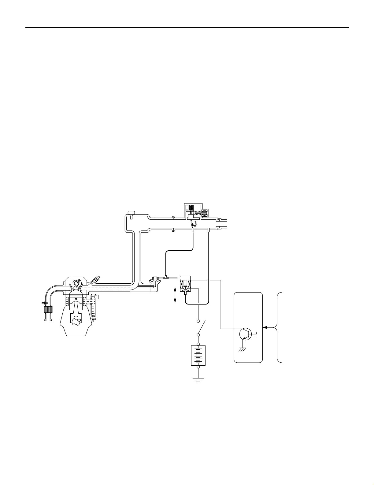
GENERAL INFORMATION (EVAPORATIVE
EMISSION CONTROL SYSTEM)
M1173005100405
The evaporative emission control system prevents
fuel vapours generated in the fuel tank from escaping
into the atmosphere.
Fuel vapours from the fuel tank flow through the fuel
tank pressure control valve and vapour pipe/hose to
be stored temporarily in the canister.
When driving the vehicle, fuel vapours stored in the
canister flow through the purge solenoid and purge
port and go into the intake manifold to be sent to the
combustion chamber.
When the engine coolant temperature is low or when
the intake air quantity is small (when the engine is at
idle, for example), the engine control unit turns the
purge solenoid off to shut off the fuel vapour flow to
the intake manifold.
This does not only insure the driveability when the
engine is cold or running under low load but also
stabilize the emission level.
17-10
SYSTEM DIAGRAM
From
fuel
tank
Canister
ENGINE AND EMISSION CONTROL
EMISSION CONTROL <MPI>
Throttle body
Engine-ECU <4G1-M/T, 4G6>,
Engine-A/T-ECU <4G1-A/T>
OFF
Purge
control
ON
solenoid
valve
Battery
Control
relay
Manifold absolute pressure
(MAP) sensor <4G1>
Air flow sensor <4G6>
Engine coolant
temperature sensor
Intake air
temperature sensor
Barometric pressure
sensor <4G6>
COMPONENT LOCATION (EVAPORATIVE
EMISSION CONTROL SYSTEM)
M1173007500216
<4G1>
Purge control
solenoid valve
<4G6>
AK300769
AB
AK204367
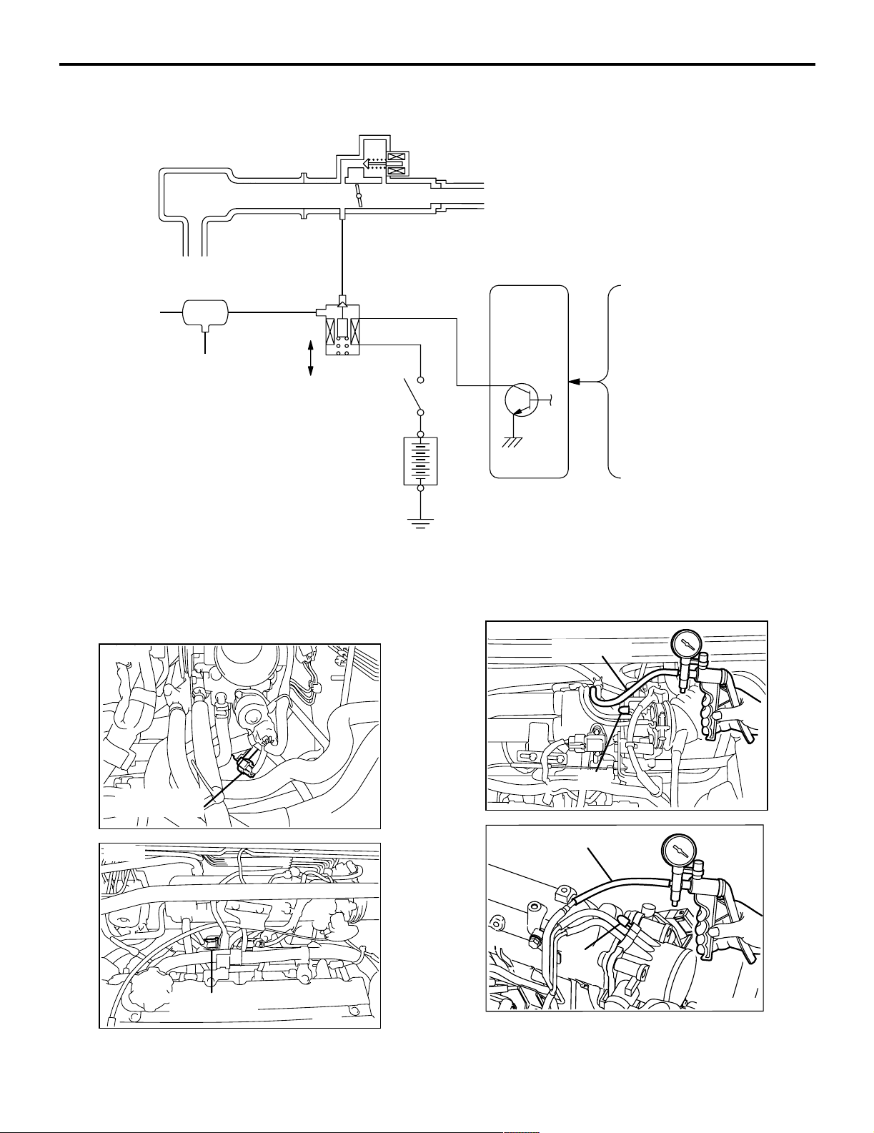
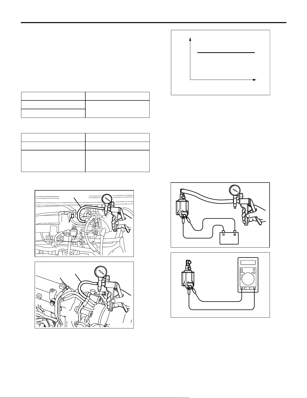
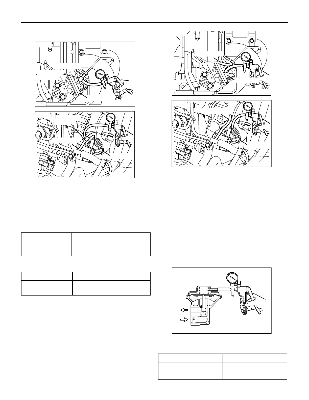
PURGE CONTROL SYSTEM CHECK
M1173001400299
<4G1>
Vacuum hose
Plug
<4G6>
AK300771
Vacuum hose
Plug
AB
AC
Purge control
solenoid valve
AK300770
AB
AK300772
AB
ENGINE AND EMISSION CONTROL
EMISSION CONTROL <MPI>
1. Disconnect the vacuum hose (red stripe) from
throttle body and connect it to a hand vacuum
pump.
2. Plug the nipple from which the vacuum hose was
removed.
3. When the engine is cold or hot, apply a vacuum of
53 kPa, and check the condition of the vacuum.
17-11
Vacuum
When engine is cold
(Engine coolant temperature: 40°C or less)
Engine condition Normal condition
At idle Vacuum is maintained.
3,000 r/min
When engine is hot
(Engine coolant temperature: 80°C or higher)
Engine condition Normal condition
At idle Vacuum is maintained.
3,000 r/min (within 3
Vacuum will leak.
minutes after engine
starts)
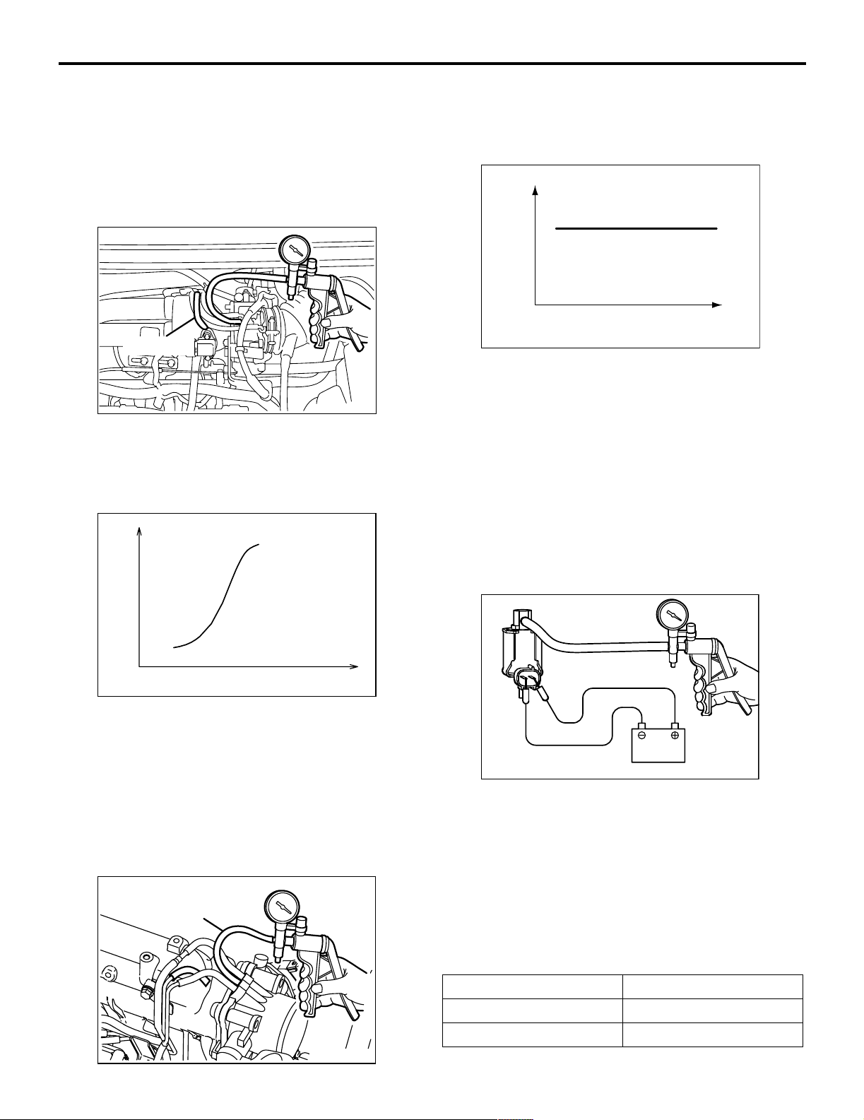
PURGE PORT VACUUM CHECK
M1173001500177
<4G1>
Vacuum hose
Plug
Engine speed (r/min)
AK100011
AC
3. Start the engine.
4. Check that a fairly constant negative pressure is
generated regardless of the engine speed.
5. If no negative pressure is generated, the port is
probably blocked and should be cleaned.
PURGE CONTROL SOLENOID VALVE
CHECK
M1173001700193
NOTE: When disconnecting the vacuum hose,
always make a mark so that it can be reconnected at
original position.
A
AK300773
<4G6>
Vacuum hose
Plug
AK300774
AB
AB
1. Disconnect the vacuum hose (red stripe) from the
throttle body and connect a hand vacuum pump to
the nipple.
2. Plug the vacuum hose (red stripe).
Battery
AK100012
AC
AK100013
1. Disconnect the vacuum hose from the solenoid
valve.
2. Disconnect the harness connector.
3. Connect a hand vacuum pump to nipple (A) of the
solenoid valve (refer to the illustration at left).
17-12
ENGINE AND EMISSION CONTROL
EMISSION CONTROL <MPI>
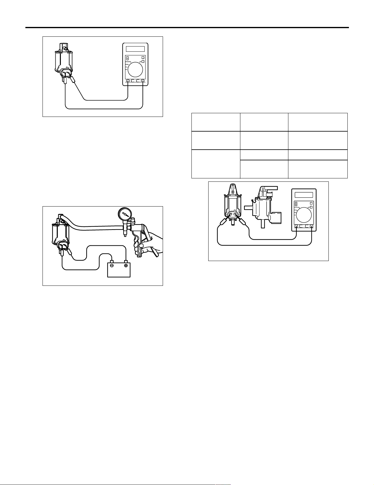
4. Check airtightness by applying a vacuum with
voltage applied directly from the battery to the
purge control solenoid valve and without applying
voltage.
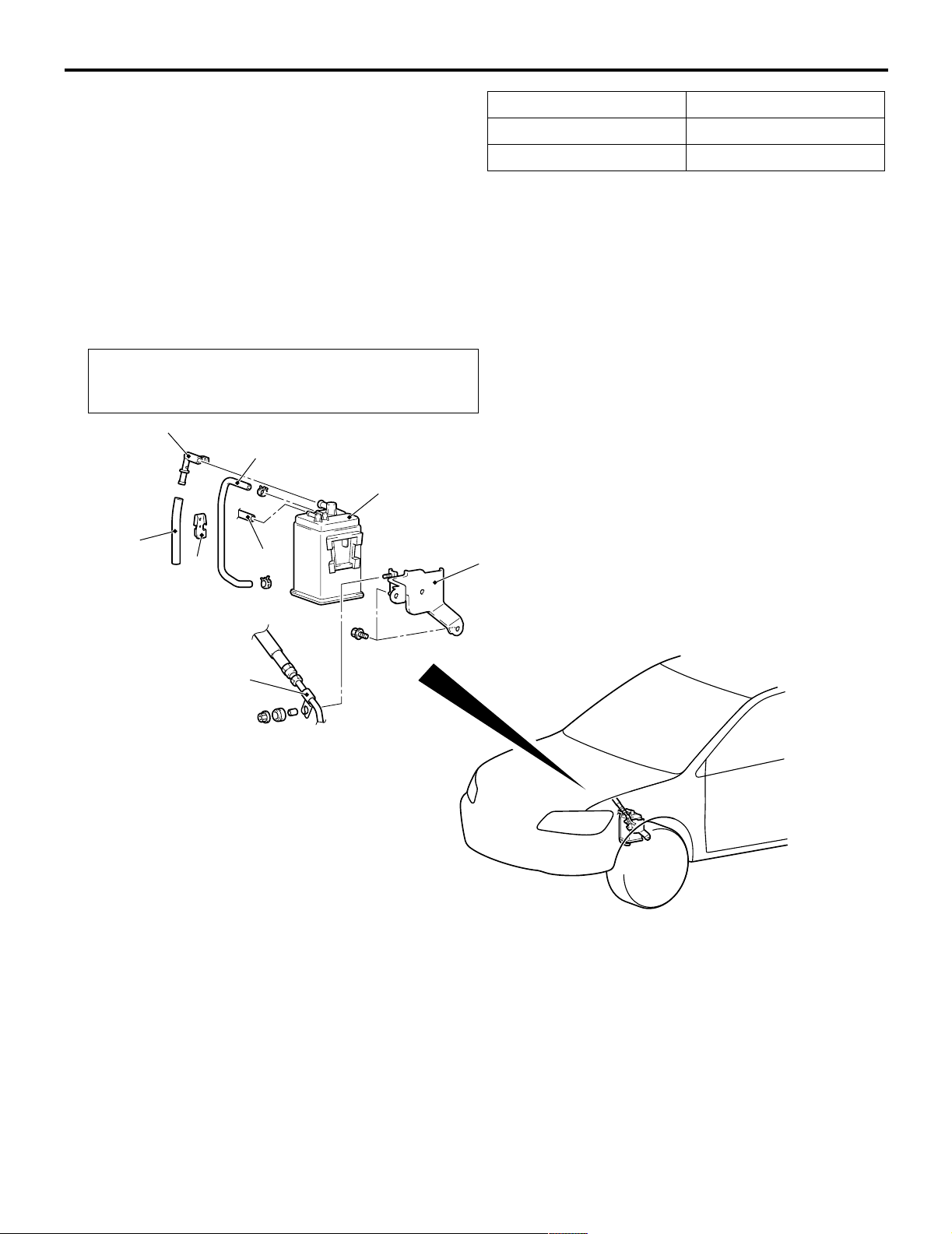
FUEL VAPOUR CANISTER REMOVAL
AND INSTALLATION
M1173004200153
Pre-removal and Post-installation Operation
Air Cleaner Assembly Removal and Installation (Refer to
GROUP 15 P.15-3).
3
2
6
4
5
1
Battery voltage Normal condition
Applied Vacuum leaks
Not applied Vacuum maintained
5. Measure the resistance between the terminals of
the solenoid valve.
Standard value: 30 − 34 Ω (at 20°C)
8
7
Removal steps
1. Emission vacuum hose connection
2. Fuel vapour control line hose
3. Fuel vapour control check valve
4. Fuel vapour control line hose
AC208253
Removal steps (Continued)
5. Fuel vapour control line clamp
6. Fuel vapour canister
7. Fuel high-pressure hose clamp
8. Fuel vapour canister bracket
AD
ENGINE AND EMISSION CONTROL
EMISSION CONTROL <MPI>
17-13
EXHAUST GAS RECIRCULATION
(EGR) SYSTEM
GENERAL INFORMATION (EGR SYSTEM)
M1173005200327
The exhaust gas recirculation (EGR) system lowers
the nitrogen oxide (NOx) emission level.
When the air/fuel mixture combustion temperature is
high, a large quantity of nitrogen oxides (NOx) is
generated in the combustion chamber.
Therefore, this system recirculates part of emission
gas from the exhaust port of the cylinder head to the
combustion chamber through the intake manifold to
decrease the air/fuel mixture combustion
temperature, resulting in reduction of NOx.
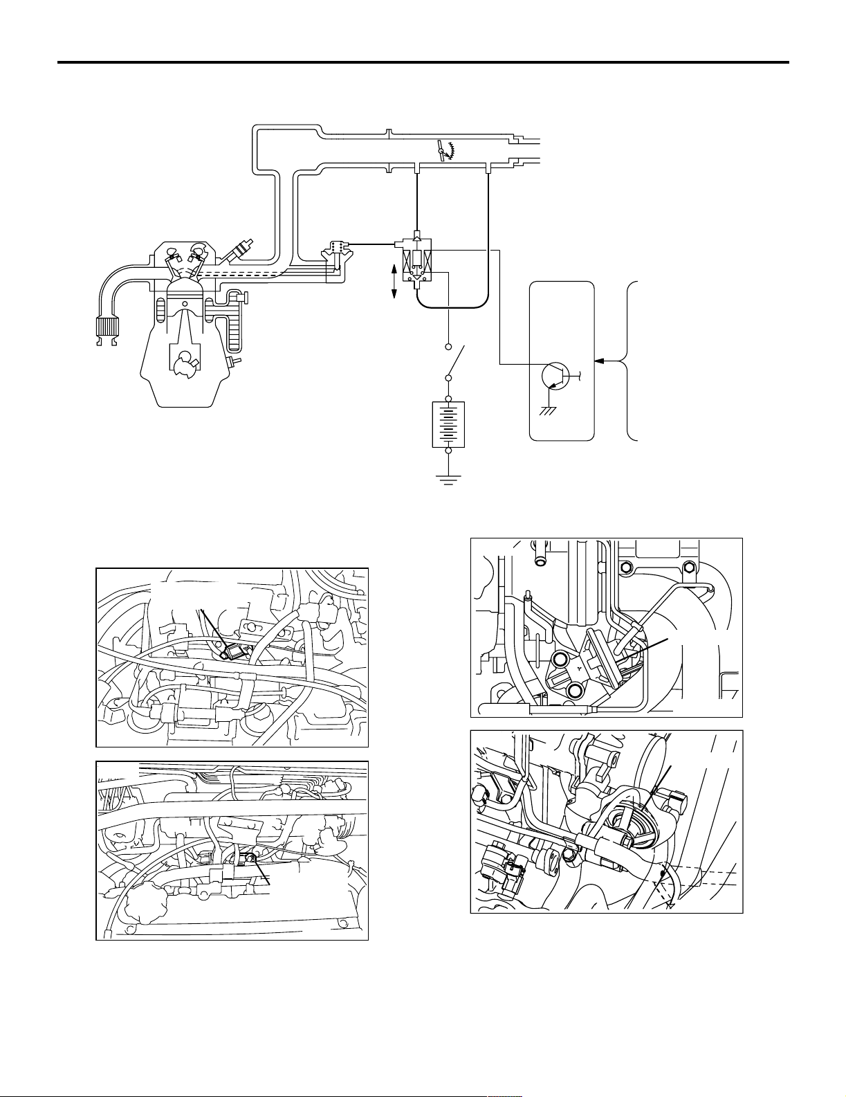
SYSTEM DIAGRAM
<4G1>
The EGR flow rate is controlled by the EGR valve so
as not to decrease the driveability.
OPERATION
The EGR valve is being closed and does not
recirculate exhaust gases under one of the following
conditions.
Otherwise, the EGR valve is opened and recirculates
exhaust gases.
• The engine coolant temperature is low.
• The engine is at idle.
• The throttle valve is widely opened.
EGR valve
OFF
ON
Battery
EGR
control
solenoid
valve
Control
relay
Engine-ECU <M/T>,
Engine-A/T-ECU <A/T>
Manifold absolute
pressure (MAP) sensor
Engine coolant
temperature sensor
Crank angle sensor
AK300775
AB
17-14
<4G6>
ENGINE AND EMISSION CONTROL
EMISSION CONTROL <MPI>
EGR
control
Solenoid
valve
OFF
EGR valve
ON
Battery
COMPONENT LOCATION (EGR SYSTEM)
M1173007600224
<4G1>
EGR control
solenoid valve
Control
relay
<4G1>
Engine-ECU
Barometric pressure
sensor
Air flow sensor
Engine coolant
temperature sensor
Crank angle sensor
AK302349
EGR valve
AB
<4G6>
AK300776
EGR control
solenoid valve
AK300778
AB
AB
<4G6>
AK300777
EGR valve
AK300779
AB
AB
ENGINE AND EMISSION CONTROL
EMISSION CONTROL <MPI>
17-15
EGR SYSTEM CHECK
M1173002600348
<4G1>
Green stripe
Three-way
terminal
<4G6>
EGR valve
Three-way
terminal
Green stripe
AK300780
EGR valve
AK300781
1. Disconnect the vacuum hose (Green stripe) from
the EGR valve, and then connect a hand vacuum
pump via the three-way terminal.
2. When the engine is hot or cold, check the
condition of vacuum by racing the engine.
When engine is cold
(Engine coolant temperature: 20°C or less)
Throttle valve Normal vacuum condition
Open quickly No vacuum will generate (the
same as barometric pressure.)
When engine is hot
(Engine coolant temperature: 80°C or higher)
Throttle valve Normal vacuum condition
AB
AB
<4G1>
Green stripe
EGR valve
AK300782
<4G6>
Green stripe
EGR valve
AK300783
AB
AB
4. Connect the hand vacuum pump to the EGR
valve nipple.
5. Check whether the engine stalls or the idling is
unstable when a vacuum of 30 kPa or higher is
applied during idling.
EGR VALVE CHECK
M1173002800223
1. Remove the EGR valve and inspect for sticking,
carbon deposits, etc. If found, clean with a
suitable solvent so that the valve seats correctly.
2. Connect a hand vacuum pump to the EGR valve.
3. Apply 67 kPa of vacuum, and check that the
vacuum is maintained.
Open quickly It will momentarily rise over 13
kPa
3. Disconnect the three-way terminal.
AKX00348
4. Apply a vacuum and check the passage of air by
blowing through one side of the EGR passage.
Vacuum Passage of air
5.3 kPa or less Air is not blown out
27 kPa or more Air is blown out
17-16
ENGINE AND EMISSION CONTROL
EMISSION CONTROL <MPI>
5. Replace the gasket, and tighten to the specified
torque.
Tightening torque:
<4G1> 21 ± 4 N⋅m
<4G6> 20 ± 2 N⋅m
EGR PORT VACUUM CHECK <4G1>
M1173002900167
Green strip
AK300784
1. Disconnect the vacuum hose (Green stripe) from
the throttle body EGR vacuum nipple and connect
a hand vacuum pump to the nipple.
2. Plug the vacuum hose (Green stripe).
Vacuum
AB
1. Disconnect the vacuum hose (White stripe) from
the throttle body EGR vacuum nipple and connect
a hand vacuum pump to the nipple.
2. Plug the vacuum hose (White stripe).
Vacuum
Engine speed (r/min)
AK100011
AC
3. Start the engine.
4. Check that a fairly constant negative is generated
regardless of the engine speed.
5. If no negative pressure is generated, the port is
probably blocked and should be cleaned.
EGR CONTROL SOLENOID VALVE
CHECK <4G1>
M1173003100238
NOTE: When disconnecting the vacuum hose,
always make a mark so that it can be reconnected at
original position.
A
Engine speed (r/min)
AK201224AB
3. Start the engine and check that, after raising the
engine speed by racing the engine, purge vacuum
raises according to engine speed.
NOTE: If there is a problem with change in
vacuum, the throttle body purge port may be
clogged and require cleaning.
EGR PORT VACUUM CHECK <4G6>
M1173002900156
White stripe
AK300786
AB
B
Battery
AKX00351
AE
1. Disconnect the vacuum hose from the solenoid
valve.
2. Disconnect the harness connector.
3. Connect a hand vacuum pump to nipple (A) of the
solenoid valve (refer to the illustration at left).
4. Check air tightness by applying a vacuum with
voltage applied directly from the battery to the
EGR control solenoid valve and without applying
voltage.
Battery voltage Normal condition
Applied Vacuum leaks
Not applied Vacuum maintained
ENGINE AND EMISSION CONTROL
EMISSION CONTROL <MPI>
AKX00352
5. Measure the resistance between the terminals of
the solenoid valve.
Standard value: 29 − 35 Ω (at 20°C)
EGR CONTROL SOLENOID VALVE
CHECK <4G6>
M1173003100249
NOTE: When disconnecting the vacuum hose,
always make a mark so that it can be reconnected at
original position.
17-17
1. Disconnect the vacuum hose from the solenoid
valve.
2. Disconnect the harness connector.
3. Connect a hand vacuum pump to nipple (A) of the
solenoid valve (refer to the illustration at left).
4. Check air tightness by applying a vacuum with
voltage applied directly from the battery to the
EGR control solenoid valve and without applying
voltage.
Battery
voltage
Not applied Open Vacuum
Applied Open Vacuum leaks
B nipple
Normal condition
condition
maintained
Closed Vacuum
maintained
A
B
C
Battery
AK201251AB
5. Measure the resistance between the terminals of
the solenoid valve.
AK100016
Standard value: 29 − 35 Ω (at 20°C)
17-18
ENGINE AND EMISSION CONTROL
EMISSION CONTROL <MPI>
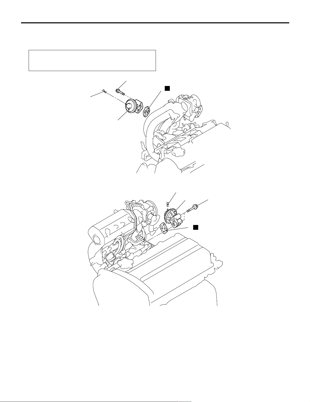
EXHAUST GAS RECIRCULATION (EGR)
VALVE REMOVAL AND INSTALLATION
M1173010500175
Pre-removal and Post-installation Operation
Air Cleaner Assembly Removal and Installation (Refer to
GROUP 15 P.15-3).
<4G1>
<4G6>
21 ± 4 N·m
N
3
1
2
AC208130
AC
1
2
19 ± 3 N·m
Removal steps
1. Emission vacuum hose connection
CATALYTIC CONVERTER
REMOVAL AND INSTALLATION
M1173003900386
Refer to GROUP 15 — Exhaust Pipe and Main Muffler P.15-11.
N
3
Removal steps (Continued)
2. EGR valve
3. EGR valve gasket
AC301219
AC

GROUP 13
FUEL
CONTENTS
MULTIPORT FUEL INJECTION (MPI) <4G1> . . . . . . . . . . . . . . 13A
MULTIPORT FUEL INJECTION (MPI) <4G6> . . . . . . . . . . . . . . 13B
13-1
FUEL SUPPLY . . . . . . . . . . . . . . . . . . . . . . . . . . . . . . . . . . . . . . 13C

NOTES

GROUP 32
POWER PLANT
MOUNT
CONTENTS
32-1
GENERAL INFORMATION . . . . . . . . 32-2
SERVICE SPECIFICATION . . . . . . . . 32-3
SPECIAL TOOL . . . . . . . . . . . . . . . . . 32-3
ENGINE MOUNTING . . . . . . . . . . . . . 32-4
REMOVAL AND INSTALLATION . . . . . . . . 32-4
TRANSMISSION MOUNTING . . . . . . 32-5
REMOVAL AND INSTALLATION . . . . . . . . 32-5
ENGINE ROLL STOPPER,
CENTERMEMBER . . . . . . . . . . . . . . . 32-7
REMOVAL AND INSTALLATION . . . . . . . . 32-7
CROSSMEMBER . . . . . . . . . . . . . . . . 32-8
REMOVAL AND INSTALLATION . . . . . . . . 32-8
32-2
POWER PLANT MOUNT
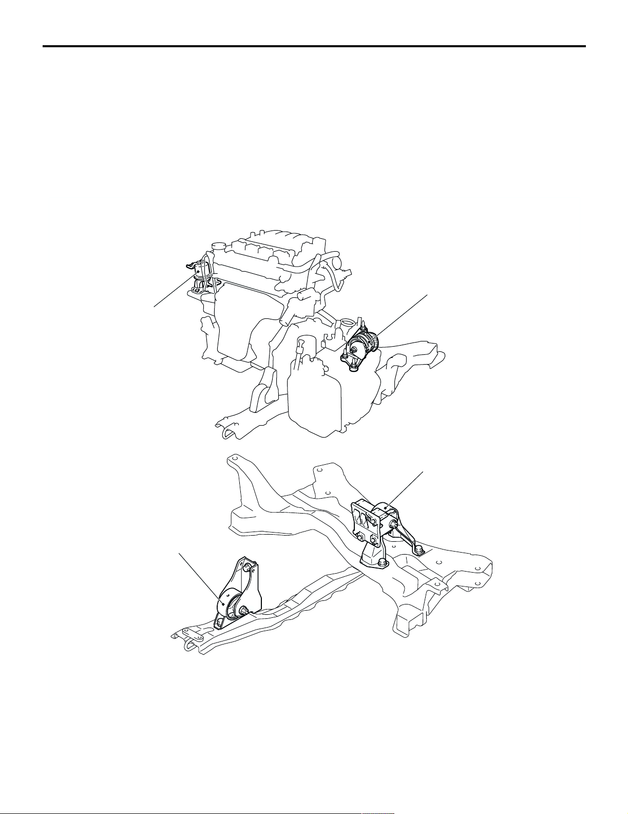
GENERAL INFORMATION
GENERAL INFORMATION
The engine mounting system employs the inertial
axis four-point suspension method, which is field
proven.
• The optimised locations of the front and rear roll
mounts well distribute their loads thereby
reducing engine idling vibrations.
CONSTRUCTION DIAGRAM
Engine front
mounting bracket
• The fore-and-aft, liquid-filled engine mount of
M1321000100340
cylinder type is adopted to reduce engine shake
for improved riding comfort.
Transmission mounting
body side bracket
Engine front roll stopper bracket
Engine rear roll stopper bracket
Y0290AU
AC107318
AC303563
AB
POWER PLANT MOUNT
SERVICE SPECIFICATION
SERVICE SPECIFICATION
Item Standard value
Protruding length of stabilizer link thread part mm 22 ± 1.5
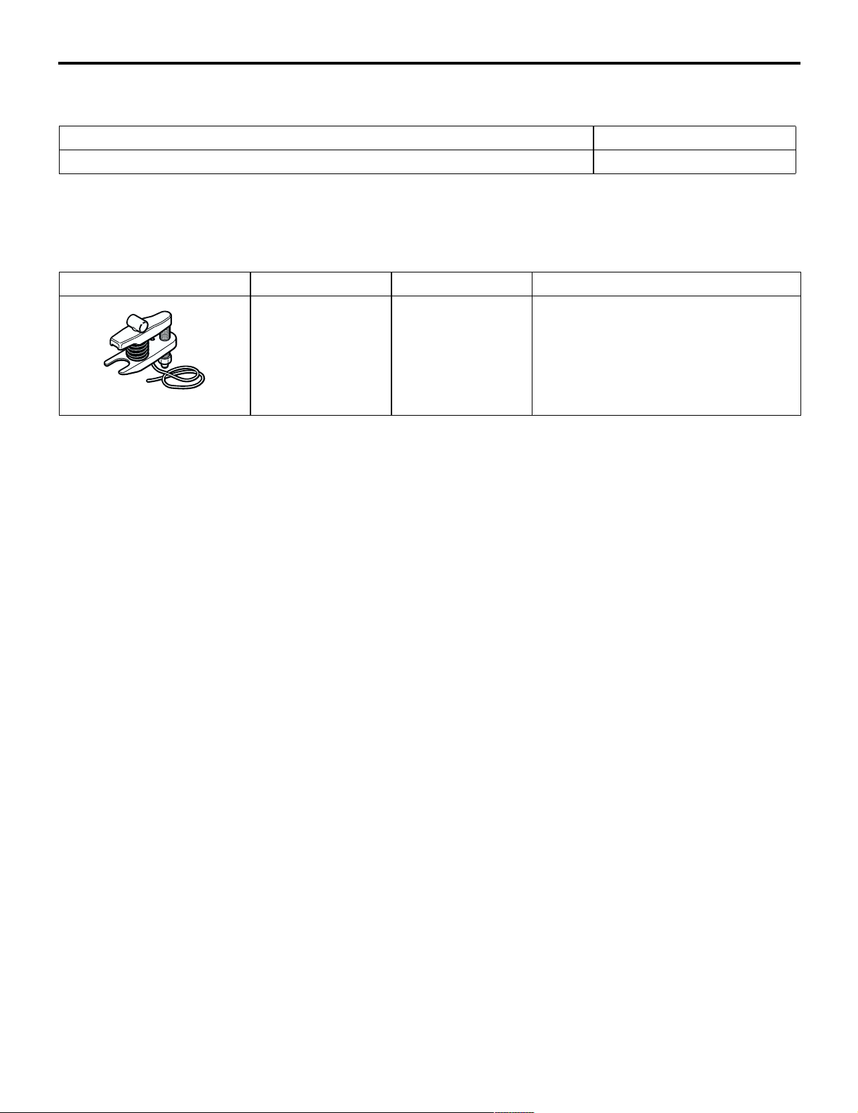
SPECIAL TOOL
Tool Numb er Name Use
MB991897 Ball joint remover Knuckle and tie rod end ball joint
disconnection
NOTE: Steering linkage puller
(MB990635 or MB991113) is also
AC106827
available to disconnect knuckle and
tie rod end ball joint.
32-3
M1321000300333
M1321000600378
32-4
POWER PLANT MOUNT
ENGINE MOUNTING
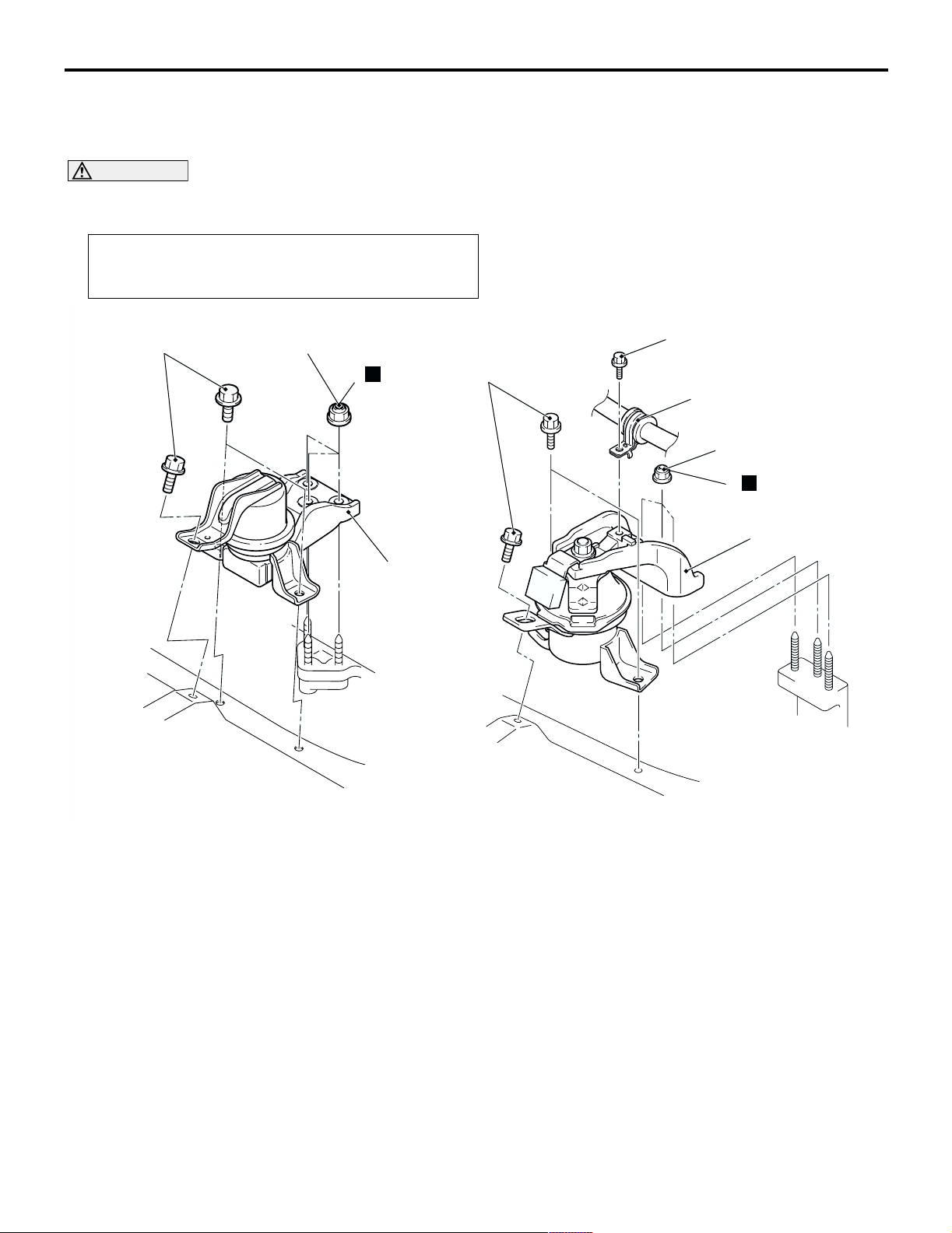
ENGINE MOUNTING
REMOVAL AND INSTALLATION
M1321001100440
CAUTION
*: Indicates parts which should be initially tightened, and then fully tightened after placing the vehicle
horizontally and loading the full weight of the engine on the vehicle body.
Pre-removal Operation
Raise the engine and transmission assembly until its weight
is not applied to the insulator, and support it securely.
<4G1> <4G6>
44 ± 10 N·m*
67 ± 7 N·m*
N
2
44 ± 10 N·m*
3
12 ± 2 N·m
1
67 ± 7 N·m*
N
2
3
AC303999 AC303968
Removal steps
1. Pressure hose clamp <4G6>
AC304304
Removal steps (Continued)
2. Self-locking nuts
3. Engine front mounting bracket
AB
POWER PLANT MOUNT
TRANSMISSION MOUNTING
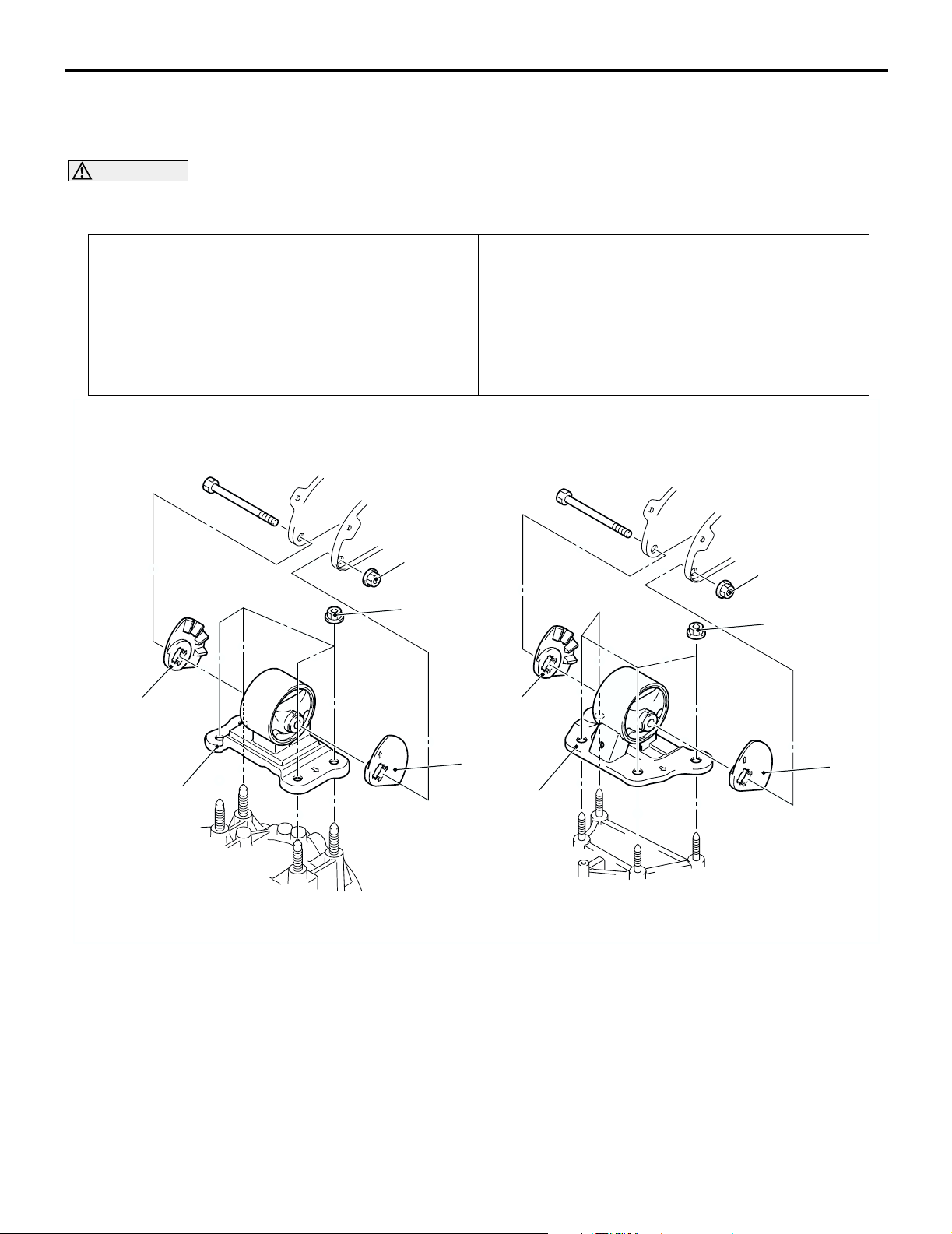
TRANSMISSION MOUNTING
32-5
REMOVAL AND INSTALLATION
M1321001400430
CAUTION
*: Indicates parts which should be initially tightened, and then fully tightened after placing the vehicle
horizontally and loading the full weight of the engine on the vehicle body.
Pre-removal Operation
• Raise the engine and transmission assembly until its
weight is not applied to the insulator, and support it
securely.
• Battery and Battery tray Removal
• Air Cleaner Removal (Refer to GROUP 15, Air Cleaner
P.15-3).
• Engine Rear Roll Stopper Bracket Removal (Refer to
P.32-7).
<M/T> <A/T>
80 ± 7 N·m*
Post-installation Operation
• Engine Rear Roll Stopper Bracket Installation (Refer to
P.32-7).
• Air Cleaner Installation (Refer to GROUP 15, Air Cleaner
P.15-3).
• Battery and Battery tray Installation
80 ± 7 N·m*
2
>>A<<
1
Removal steps
1. Transmission mounting body side
bracket
2. Transmission mounting stopper
47 ± 7 N·m*
2
AC303988
47 ± 7 N·m*
2
2
1
AC303989
AC304258
AB
32-6
POWER PLANT MOUNT
TRANSMISSION MOUNTING
INSTALLATION SERVICE POINT
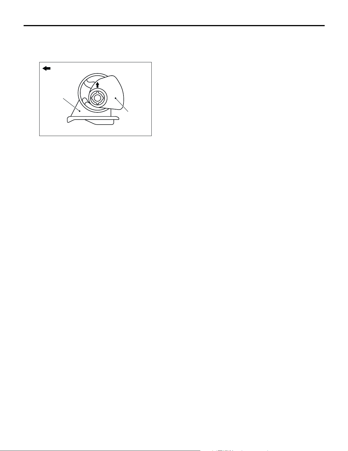
>>A<< TRANSMISSION MOUNTING
STOPPER INSTALLATION
Engine side
Transmission
mounting body
side bracket
Transmission
mounting
stopper
AC200645
AB
Install the transmission mounting stopper so that its
arrow points upward.
POWER PLANT MOUNT
ENGINE ROLL STOPPER, CENTERMEMBER
ENGINE ROLL STOPPER, CENTERMEMBER
32-7
REMOVAL AND INSTALLATION
M1321002300287
CAUTION
*: Indicates parts which should be initially tightened, and then fully tightened after placing the vehicle
horizontally and loading the full weight of the engine on the vehicle body.
Pre-removal and Post-installation Operation
Under Cover Removal and Installation
45 ± 5 N·m*
7
<4G1> <4G6>
45 ± 5 N·m*
1
3
2
45 ± 5 N·m*
5
52 ± 7 N·m*
11 ± 1 N·m
69 ± 10 N·m
6
52 ± 7 N·m*
3
>>B<<
>>A<<
52 ± 7 N·m*
4
69 ± 10 N·m
Engine front roll stopper bracket
and centermember removal
steps
1. Engine front roll stopper bracket
connecting bolt
Centermember and engine front roll
•
stopper bracket assembly
2. Engine mounting cushion stopper
<4G6>
3. Engine front roll stopper bracket
4. Centermember
1
69 ± 10 N·m
5. Engine rear roll stopper bracket
6. Transmission case rear roll stopper
7. Engine rear roll stopper bracket
AC303978
AC304309
Engine rear roll stopper bracket
removal steps
connecting bolt
bracket
AB
32-8
POWER PLANT MOUNT
CROSSMEMBER
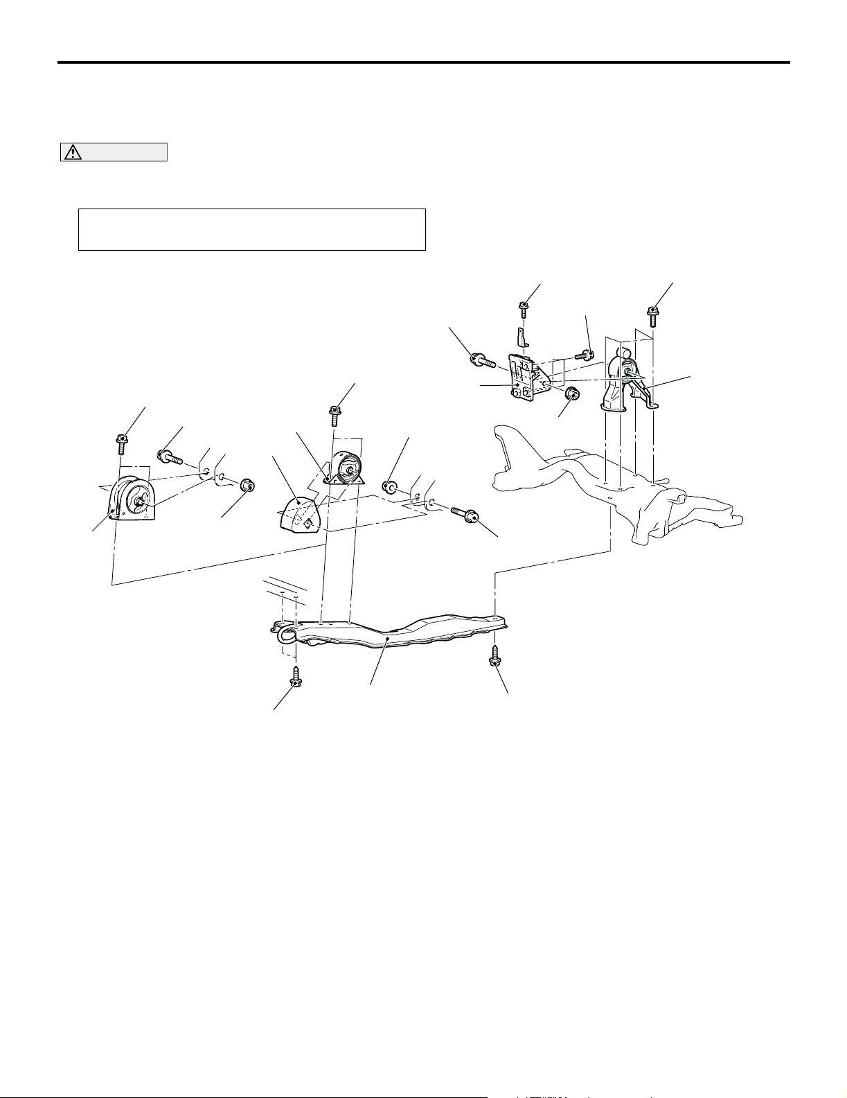
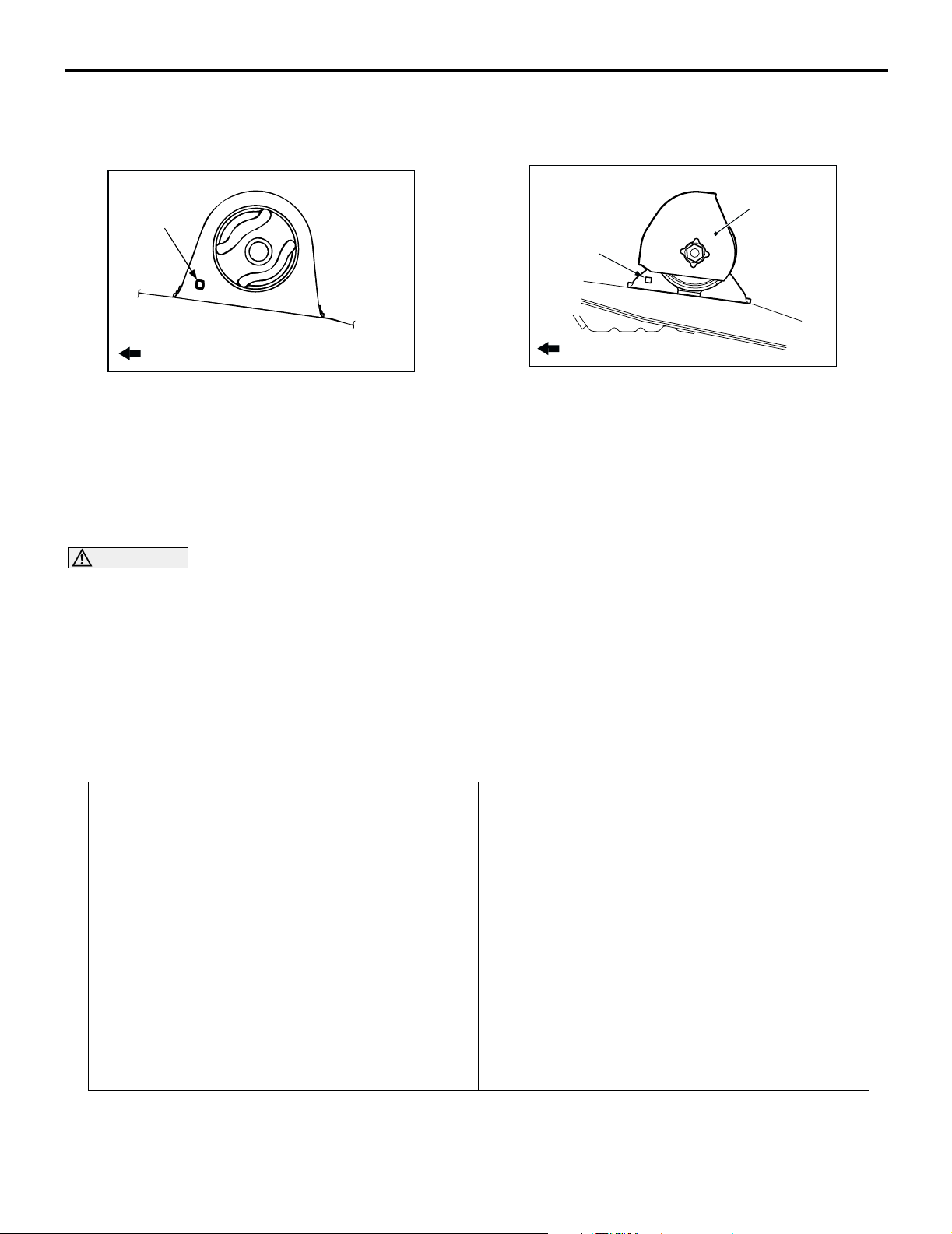
INSTALLATION SERVICE POINTS
>>A<< ENGINE FRONT ROLL STOPPER
BRACKET INSTALLATION
Hole
>>B<< ENGINE MOUNTING CUSHION
STOPPER INSTALLATION <4G6>
Engine mounting
cushion stopper
Hole
Front of vehicle
AC005918
AC
Install the engine front roll stopper bracket so that its
hole points towards the front side of the vehicle.
Install the engine mounting cushion stopper as
shown.
Front of vehicle
AC304315
AB
CROSSMEMBER
REMOVAL AND INSTALLATION
CAUTION
• Before removing the steering wheel and air bag module assembly, always refer to GROUP 52B Service Precautions P.52B-5, Air bag Module and Clock Spring P.52B-210. Also, set the front
wheels so that they are facing straight forward, and remove the ignition key. If you fail to do this,
the SRS clock spring will be damaged, causing the SRS air bag to be inoperative and serious
injury.
1
: Indicates parts which should be initially tightened, and then fully tightened after placing the
• *
vehicle horizontally and loading the full weight of the engine on the vehicle body.
2
: Indicates parts which should be temporarily tightened, and then fully tightened with the vehicle
• *
on the earth in the unladen condition.
Pre-removal Operation
• Centermember Removal (Refer to P.32-7).
• Front Exhaust Pipe Removal (Refer to GROUP 15,
Exhaust Pipe and Main Muffler P.15-11).
• Stee ring Wheel Air Bag Module Assembly Removal
(Refer to GROUP 37, Steering Wheel P.37-17).
• Power Steering Fluid Draining (Refer to GROUP 37,
On-vehicle Service P.37-13).
M1321003200368
Post-installation Operation
• Front Exhaust Pipe Installation (Refer to GROUP 15,
Exhaust Pipe and Main Muffler P.15-11).
• Centermember Installation (Refer to P.32-7).
• Clock Spring Centring (Refer to GROUP 52B, Air Bag
Modules and Clock Spring P.52B-210).
• Steering Wheel Air Bag Module Assembly Installation
(Refer to GROUP 37, Steering Wheel P.37-17).
• Power Steering Fluid Supplying (Refer to GROUP 37,
On-vehicle Service P.37-13).
• Power Steering Fluid Line Bleeding (Refer to GROUP 37,
On-vehicle Service P.37-13).
• Press the dust cover with a finger to check whether the
dust cover cracked or damaged.
• Checking Steering Wheel Position with Wheels Straight
Ahead.
• Front Wheel Alignment Check and Adjustment (Refer to
GROUP 33, On-vehicle Service P.33-5).
Loading…