
twist 200 E
Installation and Operating Instructions 1 — 32
46685V001-292012-0-OCE-Rev.D_GB

Table of contents
General Information ……………………………………………… 3
Symbols ………………………………………………………………………………. 3
Safety instructions …………………………………………………………………. 3
Intended use ………………………………………………………………………… 3
Improper use ………………………………………………………………………… 4
Permitted gate wing dimensions ……………………………………………… 4
Technical data ………………………………………………………………………. 4
Dimensions ………………………………………………………………………….. 4
Functional description ……………………………………………………………. 4
Installation preparations ……………………………………….. 6
Safety instructions …………………………………………………………………. 6
Tools required ……………………………………………………………………….. 6
Personal safety equipment ……………………………………………………… 6
Scope of supply …………………………………………………………………….. 6
Installation ……………………………………………………………. 7
Tips for installation ………………………………………………………………… 7
Drive installation position ……………………………………………………….. 7
A/B dimension table ………………………………………………………………. 8
1. Setting the end position for gate «OPEN» ………………………………. 8
2. Setting the end position for gate «CLOSE» …………………………….. 8
Setting the limit switches ………………………………………………………… 9
Instructions for setting the end positions …………………………………… 9
Emergency unlock for power failure and installation …………………… 9
Removing cover ………………………………………………………………….. 10
Installation of ttings …………………………………………………………….. 10
Examples for A/B dimensions ……………………………………………….. 10
Opening gate outwards ………………………………………………………….11
Post or pillar tting …………………………………………………………………11
Gate wing tting ……………………………………………………………………11
Timber post ttings ………………………………………………………………..11
Installing the control unit ………………………………………………………. 12
Connection to mains power (AC 230 V) ………………………………….. 12
Connecting drive to control unit ……………………………………………… 12
Programming the hand-held remote control …………………………….. 13
Checking the direction of running …………………………………………… 13
Initial operation …………………………………………………… 14
General information ……………………………………………………………… 14
Preparations for continuous operation ……………………………………. 14
Enabling continuous operation ………………………………………………. 14
Adjusting the force tolerance …………………………………………………. 15
Programming the hand-held remote control …………………………….. 15
Potentiometer for force tolerance …………………………………………… 19
Button on control unit …………………………………………………………… 19
Light-emitting diodes (LED) …………………………………………………… 20
DIP switches ………………………………………………………………………. 20
Radio connector ………………………………………………………………….. 21
Automatic closing function ……………………………………………………. 21
Connection to mains power (AC 230 V) ………………………………….. 21
Fuses ………………………………………………………………………………… 21
Transformer terminal ……………………………………………………………. 22
Connecting drives ……………………………………………………………….. 22
Connecting safety device ……………………………………………………… 22
Connecting button ……………………………………………………………….. 22
Connecting warning light ………………………………………………………. 22
Connecting external consumers …………………………………………….. 23
Potential-free relay contact …………………………………………………… 23
Motor PCB ………………………………………………………………………….. 23
TorMinal interface ………………………………………………………………… 23
Accessories ……………………………………………………….. 24
Safety instructions ……………………………………………………………….. 24
Warning light ………………………………………………………………………. 24
Key switch ………………………………………………………………………….. 24
Photo eye …………………………………………………………………………… 24
Connector wiring set ……………………………………………………………. 25
Main switch ………………………………………………………………………… 25
External antenna …………………………………………………………………. 25
Electric lock DC 24 V …………………………………………………………… 26
Maintenance and care …………………………………………. 27
Safety instructions ……………………………………………………………….. 27
Regular testing ……………………………………………………………………. 27
Miscellaneous …………………………………………………….. 28
Disassembly ……………………………………………………………………….. 28
Disposal …………………………………………………………………………….. 28
Troubleshooting …………………………………………………. 29
Tips on troubleshooting ………………………………………………………… 29
Connection diagram ……………………………………………. 31
Wiring diagram …………………………………………………… 32
Operation / Use …………………………………………………… 16
Safety instructions ……………………………………………………………….. 16
Normal mode ………………………………………………………………………. 16
Summer-winter mode …………………………………………………………… 16
Intermediate stop ………………………………………………………………… 16
Obstacle detection ………………………………………………………………. 16
Opening and closing gate …………………………………………………….. 16
Control unit reset …………………………………………………………………. 17
Radio receiver …………………………………………………………………….. 17
Display and button explanation ……………………………………………… 17
Programming the hand-held remote control …………………………….. 17
Deleting a hand-held remote control button from the radio receiver 18
Deleting all radio codes of a channel ……………………………………… 18
Deleting the radio receiver memory ……………………………………….. 18
Connecting external antenna ………………………………………………… 18
Troubleshooting ………………………………………………………………….. 18
Additional functions and connections …………………. 19
Jumper ………………………………………………………………………………. 19
– 2

General Information
Symbols
ATTENTION SYMBOL:
Important safety instructions!
To ensure personal safety, it is important to observe all
instructions. Save these instructions!
NOTE SYMBOL:
Information, useful advice!
Refers to a respective picture in the introduction or main text.
Safety instructions
General
¾ These installation and operating instructions must be read, understood
and complied with by persons who install, use or perform maintenance
on the drive.
¾ The manufacturer does not accept liability for damage or interruptions
to business resulting from non-observance of the installation and
operating manual.
¾ Always ensure compliance with accident prevention regulations and
current standards in each respective country.
¾ All applicable Directives and standards must be observed for
installation and operation, such as: EN 12453, EN 12604, EN 12605
¾ Before working on the gate or the drive always disconnect the control
unit from the power supply and lock to prevent reactivation.
¾ All electrical wiring must be firmly secured to prevent displacement.
¾ There is a risk of persons being crushed or cut by the mechanism
or sharp edges of the door.
¾ Never operate a damaged drive.
¾ After installation and commissioning all users must be instructed in
the function and operation of the swing gate drive.
¾ Only use OEM (Original Equipment Manufacturer) spare parts,
accessories and mounting material.
Storage
¾ The drive must be stored in an enclosed, dry area at a room
temperature of -20 — +70 °C.
¾ The drive should be stored horizontally.
Operation
¾ Do not allow children or persons who have not been instructed to
operate the gate control unit.
¾ Open and close the gate only if there are no children, persons, animals
or objects within its range of motion.
¾ Actuate the gate wirelessly only if you have an unobstructed view.
¾ Never put your hand near the gate when it is moving or near moving
parts.
¾ Regularly check the safety and protection functions and repair faults
when they are detected. See Care and maintenance.
¾ Drive through the gate only when it has opened completely.
¾ Set the force tolerance as low as possible.
¾ For automatic closing the main and auxiliary closing edges must be
secured in accordance with the applicable directives and standards.
¾ Always remove the key to ensure that unauthorized persons cannot
unlock the drive and open the gates.
Radio remote control
¾ The remote control must only be used for devices and systems in which
radio interference will not endanger people, animals or objects or the
risk is reduced by other safety devices.
¾ The user must be made aware that systems that pose an accident risk
should only be operated – if at all – by remote control if the user can
actually see the door.
¾ The radio remote control may only be used if the door’s movement
can be watched and no persons or objects are within the range of
movement.
¾ Store the hand-held transmitter so that unintended operation, e.g., by
children or animals, is impossible.
¾ The operator of the radio system is not protected from faults due to
other telecommunications equipment or devices (e.g. radio-controlled
systems that are licensed to operate in the same frequency range).
If substantial interference occurs, please contact your appropriate
telecommunications office which has radio interference measuring
equipment (radiolocation).
¾ Do not operate the hand-held transmitter in areas with sensitive radio
communications or systems (e.g. airports, hospitals).
Type plate
¾ The type plate is inside the cover of the control unit.
Intended use
NOTE!
After installation of the drive the person responsible for the
installation must complete an EC declaration of conformity
for he gate system in accordance with the Machinery
Directive 2006/42/EC and apply the CE mark and a type
plate. This is also required for private installations and
also if the drive is retrofitted to a manually operated gate.
This documentation and the Installation and Operating
Instructions are retained by the operator.
¾ The drive is intended exclusively to open and close doors. Any other
use does not constitute intended use. The manufacturer accepts no
liability resulting from use other than intended use. The user bears the
sole responsibility for any risk involved. It also voids the warranty.
¾ Doors automated with an operator must comply with the valid standards
and directives: e.g. EN 12453, EN 12604, EN 12605.
¾ Maintain the safety clearances between the gate and surroundings as
specified in EN 12604.
¾ The drive must be in good technical condition, and it must be used for
its intended purpose with awareness of the hazards as described by
the installation and operating manual.
¾ Faults that may affect safety must be repaired without delay.
¾ The gate must have very little play in the hinges.
¾ The gates must be stable and resistant to twisting, i.e. they must not
bend or twist when opening and closing.
¾ The DSTA24 control unit and the twist 200 drive must only be used
together.
¾ The DSTA24 control unit and the twist 200 drives are designed for
private use.
¾ The electric drive is designed exclusively for opening and closing one
or two-wing swing gate installations.
– 3
General Information
Improper use
¾ Opening or closing flaps, e.g. for access to roofs or similar.
¾ Operation with 2x twist200E, EL, on one wing is prohibited.
¾ Mixed operation with 1 x twist 200 E, EL, and 1 x twist XL is permitted
only in combination with the twist XS # 3248V000 conversion kit.
Permitted gate wing dimensions
Length: min. 0.8 m …max. 2.5 m
Height: max. 2.5 m
Weight: max. 200 kg
Open area: min. 50 %, regardless of wing size
Gate inclination: 0 %
With lift gates
NOTE!
Risk of injury with lift gates that are not balanced!
Gates that lift must be optimally balanced to ensure that they
cannot accidentally fall closed when not locked!
NOTE!
The twist 200E must not be operated with a lift gate except
in combination with the 3129V001 (left wing of gate) and
3129V003 (right wing of gate) gate brackets!
• Weight: max. 120 kg
• Length: max. 2.5 m
• Gate inclination: max. 10 %
Technical data
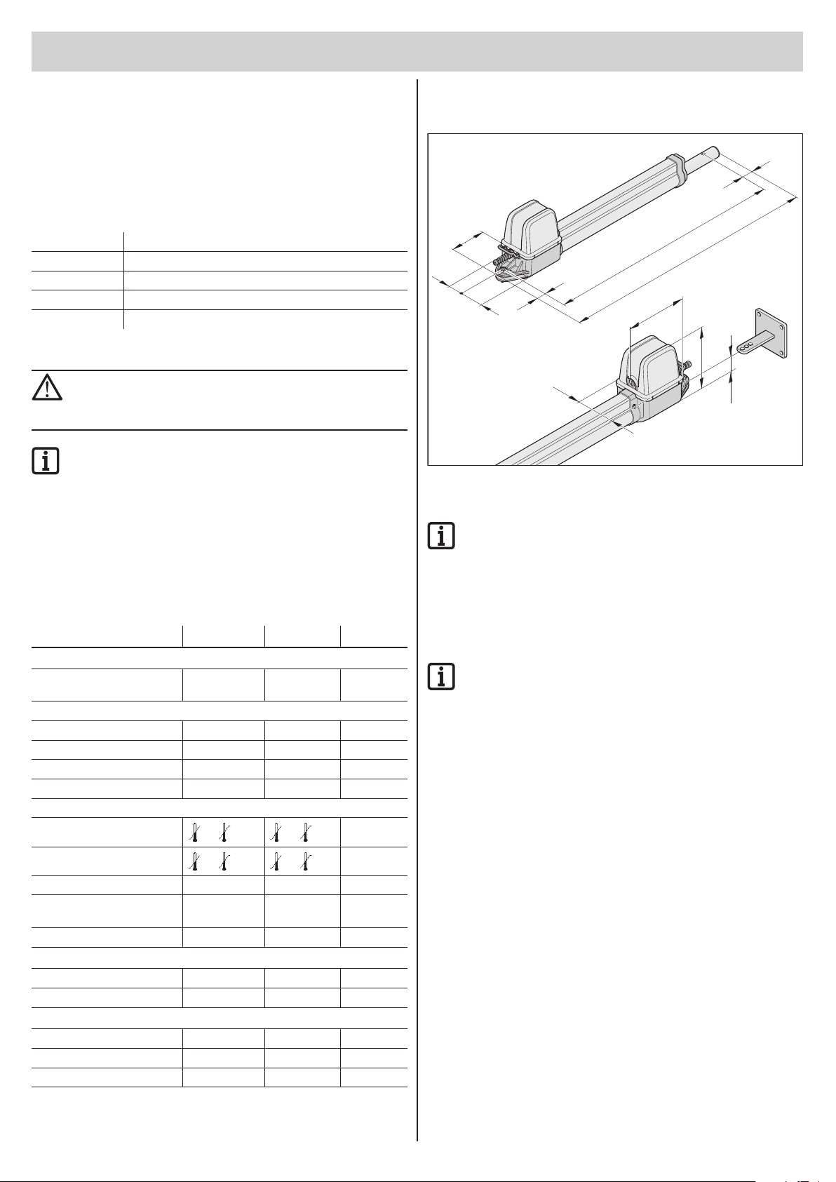
Dimensions
All dimensions are in millimeters.
17
52
710 — max. 1100
min.
177
53
Cmin. 670 — Cmax. 1060
53
23
185
106
40
Functional description
NOTE!
The end positions (gate OPEN + CLOSE) are set by internal
limit switches in the drive and detected during operation.
The gate wing is opened and closed by retracting and extending
the gate operator. When the defined end positions are reached the drive
is automatically switched off by the limit switch.
1-wing 2-wing Unit
General
Runtime depending
on A/B size
Protection type
Drive IP 44 IP 44
Controller housing IP 65 IP 65
Rated voltage 220 …240 220 …240 AC/V
Rated frequency 50 50 Hz
Operating temperature range
Drive
Controller housing
Lift (per drive) 390 390 mm
Max. tension and compress.
force
Duty cycle: 15 15 %
approx.
10 …22
-30 +70 -30 +70
-30 +70 -30 +70
2000 2000 N
approx.
15 …27
seconds
°C
°C
Stand by
Rated current consumption 20 20 mA
Rated wattage 2,2 2,2 W
Rating
Motor voltage: approx. 22 approx. 20 DC/V
Rated current consumption: approx. 3 approx. 6 A
Rated power consumption: approx. 118 approx. 234 W
Workplace-related emission value < 75 dBA – drive only
Closing the gate
NOTE!
An end stop at the «gate CLOSED» end position is absolutely
essential. An electric lock can be installed as an additional
lock.
The gate wing does not require a lock, because the drive is self-locking
(retained by the control unit). The gate cannot be pushed open manually
without damaging the drive or the fittings.
Wireless actuation
The drive can be actuated with the included hand-held transmitter once
the transmitter has been set to the radio receiver.
Safety devices
The control system has an automatic force monitor. If the drive requires
more force for opening or closing than the value saved during the learning
run, the drive stops and reverses (gate «CLOSE» direction) or remains
stationary (gate «OPEN» direction).
Various safety devices can be connected to the control unit (see additional
functions and connections).
e.g.
• Photo eye
• Safety contact strip with additional evaluation unit
– 4

General Information
Responsible for documents
Declaration of Installation
in accordance with the Machinery Directive 2006/42/EC, appendix II, part 1 B
as of the identi cation twist 2 00 E 01/10 complies with the Machinery Directive 200 6/42/EC and is speci ed for instal —
lation in a door system.
• The following fundamental safety requirements in accordanc e with appendix I have been applied and observed:
— General principles no. 1
— 1.2 Safety and reliability of control units
Safety input I terminal 17 + 18: Cat 2 / PL C
Internal force limitation Cat 2 / PL C
Safety categories in accordance with EN 13849 — 1:2008
• Compliant with the regulations of the EC Building Products Guideline 89/106/EC.
For the operating forces part, the respec tive initial testing has been carried out in consultation with recognized
inspecting authorities. In doing so, the harmonized standards EN 13241-1, EN 12453 and EN 12445 have been applied. For the tested combinations, refer to the table «Reference list» on t he Internet under www.sommer.eu.
• Compliant with the Low Voltage Directive 2006/95 /EC.
• Compliant with the Directive on Electromagnetic Compatibilit y 2004/1 08/EC.
• The technical documentation was drawn up in accordanc e with appendix VII B.
The product may only be put into operation after it has been established t hat the door system complies with the regulations of the Machinery Directive.
for the installation of an incomplete machine
SOMMER Antriebs- und Funktechnik GmbH
Hans — Böckler — Straße 21 — 27
73230 Kirchheim unter Teck
Germany
hereby declares that the control unit
twist 200 E
Kirchheim, 29.12.2009
Jochen Lude
EU Declaration of Conformity
SOMMER Antriebs- und Funktechnik GmbH hereby declares that the twist
200 E gate drive and the SOMMER Antriebs- und Funktechnik GmbH
hand-held radio transmitter conform to the basic requirements and the
other applicable regulations of Directive 1999/5/EC.
The Declaration of Conformity is available at the following web site:
www.sommer.eu/mrl
– 5
Installation preparations
Safety instructions
NOTE!
The control unit is supplied with a mains cable for use in
installing the drives only. On completion of installation
disconnect the mains cable and replace it with permanent
wiring. The mains cable is not approved for constant or
outdoor operation.
NOTE! DANGER OF DESTRUCTION BY VOLTAGE
FLUCTUATIONS.
Voltage fluctuations e.g.: caused by welders may destroy
the control unit.
Do not connect the control unit to the mains until all
installation work is completed.
¾ Install all wiring for the drive in ducts approved for the purpose (e.g. for
underground installation).
¾ The control unit must be connected to the power supply by an
electrician only.
¾ Installation must be in accordance with the installation and operating
manual.
¾ Remove or disable locking devices (electric locks, bars etc.) before
installing the drive.
¾ Ensure that the drive is securely fastened to posts, pillars and gate
wing to withstand forces generated when opening and closing the gate.
¾ Cover or remove the drive when welding fittings to posts or gate wing
to prevent damage from sparks or welding beads.
¾ If a button is used for opening or closing, it must be installed at a height
of at least 1.6 m to prevent operation by children.
¾ Use only approved fasteners (e.g. wall plugs) in public areas.
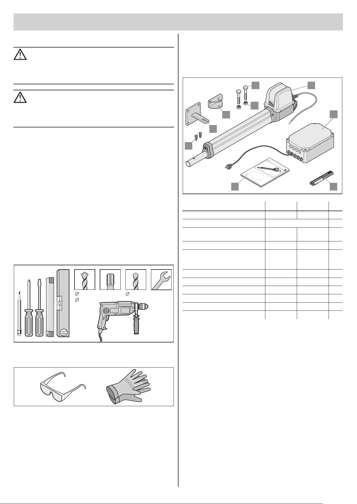
Tools required
14 mm M10 8,2 mm 17 mm2x
8mm
Mit SOMMER sind Sie immer gut ausgerichtet!
Scope of supply
¾ Check the package before installation to avoid unnecessary work and
expense if a part is missing.
¾ The actual scope of supply may vary depending on the design of the
drive.
7
8
5
6
clos
e
9
open
S
O
TO
M
MM
a
RANTRIEBE
de
E
i
n
R
G
e
r
m
a
n
y
c
l
o
twist200
s
e
o
p
e
n
D
M
o
n
t
a
ge-
u
nd
B
ed
ienun
g
s
a
n
l
e
i
t
un
g
D
1
Complete set 1-wing 2-wing
Weight 9,1 13,8 kg
Package (L x W x H): 800 x 200 x 220 mm
1. Installation and Operating
Instructions
2. Drive with cable 1 x 2 x
3. Control unit in housing
(incl. radio receiver, transformer
and power plug)
4. Hand-held transmitter with battery 1 x 1 x
5. Fittings for gate wing 1 x 2 x
6. Fittings for post or pillar 1 x 2 x
7. Stainless steel hex bolt M10x45 2 x 4 x
8. Stainless steel locknut M10 2 x 4 x
9. Plug 2 x 4 x
1 x 1 x
1 x 1 x
2
3
4
Personal safety equipment
¾ Safety glasses (for drilling)
¾ Work gloves
– 6
Installation
10
3
2 x 0,75 mm
8
E
S
S
C
C
P
M
M
1
2 x 0,75 mm
2
6
2
4 x 0,75 mm
3
2
2
2 x 0,75 mm
O
5
3 x 1,5 mm
AC 230V
2
2
E
B
E
I
R
TORANT
ER
M
SOM
4 x 0,75 mm
2
4
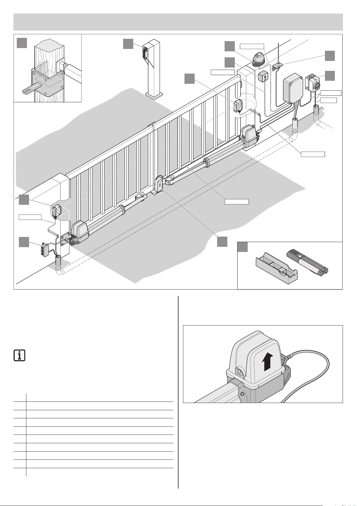
Tips for installation
• Define the installation location together with the operator.
• Do not install the housing where it could be seen from the street,
otherwise the housing and control unit may be damaged by vandalism.
• If the gate wings are larger than 2 m or there are two wings, attach
a threshold or a threshold bar to the gate.
NOTE!
Additional pulse transmitters are: hand-held transmitters,
Telecody, wireless indoor switches and key switches. In the
case of the hand-held transmitter, Telecody or the wireless
indoor switches a connecting line to the drive is not required
(contact your dealer).
1. Warning light DC 24 V
2. Key switch (1 or 2 contact)
3. Photo eye
4. Connector wiring set 7 m
5. Main switch (lockable)
6. rod antenna (with cable)
7. Electric lock DC 24 V
8. Telecody
9. Car/wall holder for hand-held transmitter
10. Timber post ttings
7
9
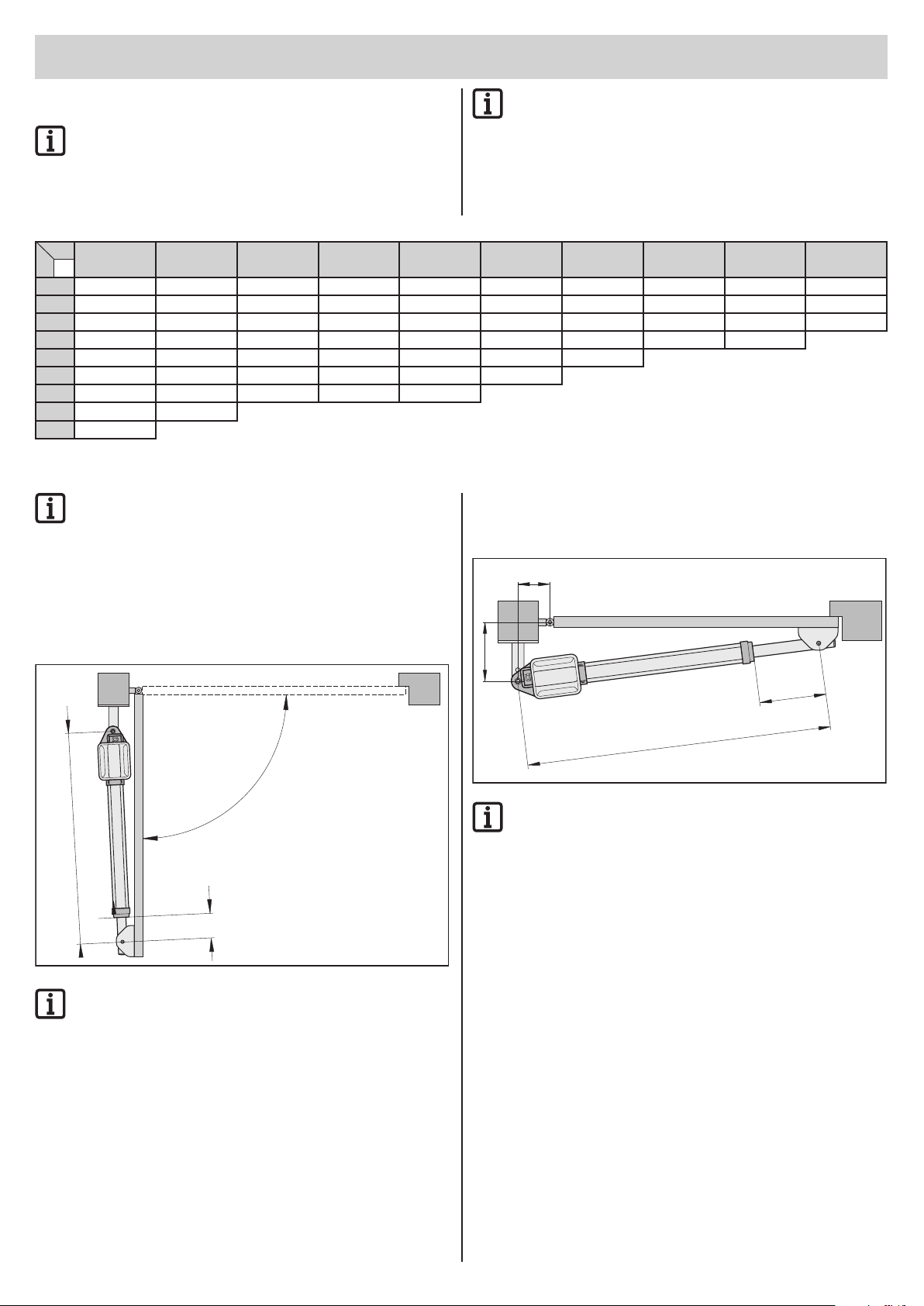
Drive installation position
Install drive horizontally. Note installation position of motor; it must always
point upright.
– 7
Installation
A/B dimension table
NOTE!
Before installation dene the A/B dimensions. Without them
the drive cannot be correctly installed and operated.
• Note different post or pillar dimensions.
A 80 100 120 140 160 180 200 220 240 260
W D
100 90° 100° 110° 115° 125° 130° 120° 110° 105° 100°
120 90° 100° 105° 115° 120° 125° 110° 105° 100° 95°
140 90° 100° 105° 110° 115° 115° 105° 100° 95° 90°
160 90° 95° 105° 110° 115° 110° 100° 95° 90°
180 90° 95° 100° 105° 110° 100° 95°
200 90° 95° 100° 105° 100° 90°
220 90° 95° 100° 95° 90°
240 90° 95°
260 90°
NOTE!
Follow these instructions to set the end positions.
This ensures that:
• the drive is at maximum rigidity in the CLOSED position
• the maximum possible path is fully used
• only one limit switch (CLOSED position) must be set
2. Setting the end position for gate
«CLOSE»
NOTE!
Select A/B dimensions so the desired opening angle is
reached. The specied opening angle (D) is a reference value
for the largest possible angle.
If the gate wings are larger than 1.5 m, the B dimension must
be at least 140 mm.
• Dimensions A, B in mm
• D = largest possible opening angle in degrees
• 1 revolution = 1.25 mm adjustment path when
adjusting the limit switch
A
1. Setting the end position for gate
«OPEN»
D
min
C = 670 mm
C1 = 40 mm
min
NOTE!
Gate «OPEN» end position preset, approx. C1 = 40 mm.
1. Measure A and B dimension and compare with preset values from A/B
dimension table.
2. Install the post tting on post in accordance with the selected A/B
dimensions.
3. Move the gate to the desired OPEN position. Note the maximum
possible opening angle D from the A/B dimension table.
4. Remove drive from package and attach to post tting. The drive at
maximum retraction as delivered.
5. Fasten drive temporarily to gate with gate tting, e.g. with a clamp.
6. Set gate «AUF/open» end position. See «Setting the end switches»
B
C1 =
max
430 mm
C = 1060 mm
max
NOTE!
End position gate “CLOSE” preset, approx. C1 = 430 mm.
This corresponds to the maximum possible value for C1 or
Cmax. Do not exceed maximum values for C1 = 430 mm and
C = 1060 mm.
1. Close the gate manually. Unlock the drive to allow this (see «Unlocking
the drive», page 9).
2. Measure dimension C1 on drive and check that C1 is no greater than
C1max = 430 mm.
3. Set dimension C1. See «Setting the limit switches».
4. Connect the control unit to the preinstalled plug and connect the drive
(see «Connecting drive to control unit»).
– 8
Setting the limit switches
NOTE!
Before setting the limit switches read the «Information on
setting the end positions».
If the information and instructions are not observed the drive
and control unit may be irreparably damaged.
Gate CLOSE
Installation
close
ope
n
close
close
open
close
open
Gate OPEN
close
open
open
Instructions for setting the end
NOTE!
Always reposition the limit switch connector cable after
adjustment to prevent it from being jammed in the gate
operator.
Emergency unlock for power
failure and installation
NOTE!
Actuate the emergency lock only with the control
disconnected from the power and locked to prevent
reactivation.
In case of power failure the gate can be opened or closed manually after
unlocking the drive, regardless of its position.
Unlocking the drive
11
6
7
positions
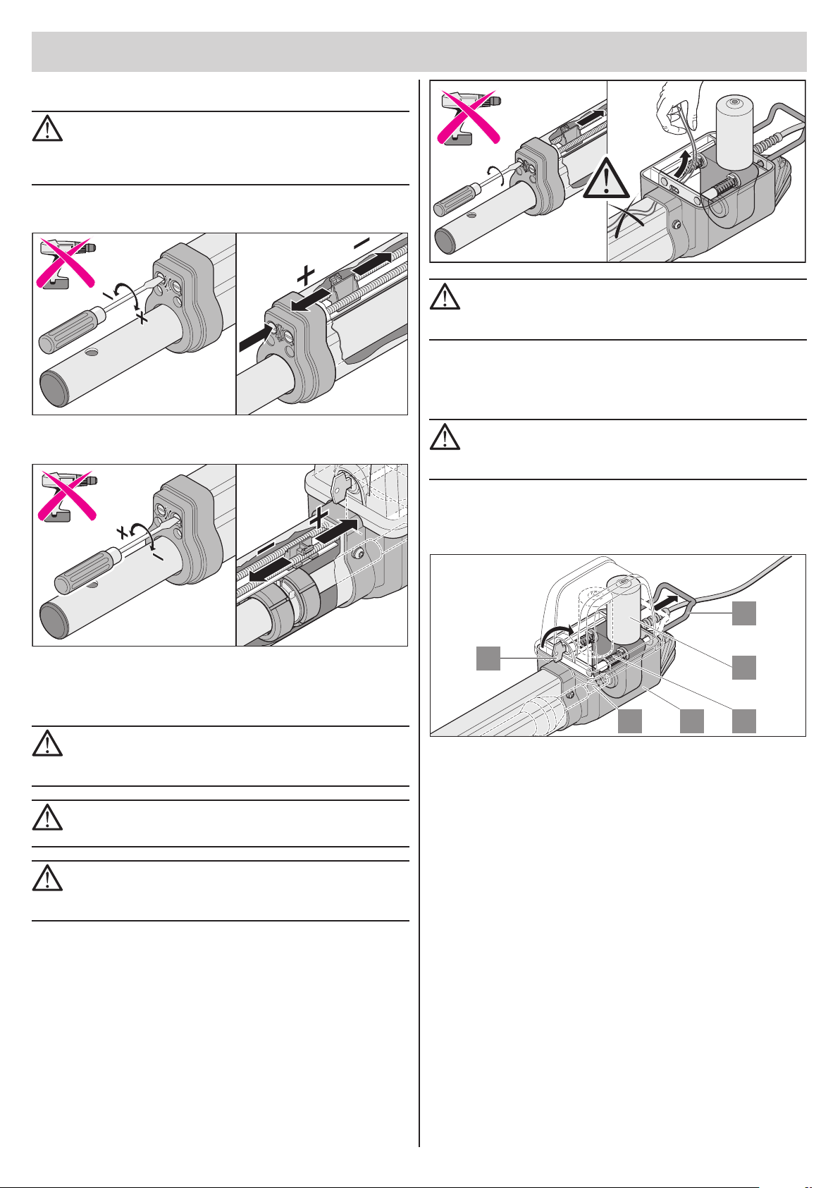
NOTE!
Do not adjust limit switches with a battery-powered
screwdriver or a similar tool. This may destroy the limit
switches.
NOTE!
Never connect drive to 230V. This will destroy the motor
immediately.
NOTE!
Before installation set the limit switches for «gate OPEN» and
«gate CLOSE». The gate wing must not come into contact with
the housing, or it may be damaged.
13 12
1. Turn key (6) 90° clockwise — this unlocks the emergency release
bracket (11).
2. Pull the emergency release bracket (11) away from the housing (12),
the motor (7) is pulled down from the spindle (13). The springs (36)
push the motor (7) down off the spindle (13).
Make unlocking easier: move gate wing manually.
36
– 9
Installation
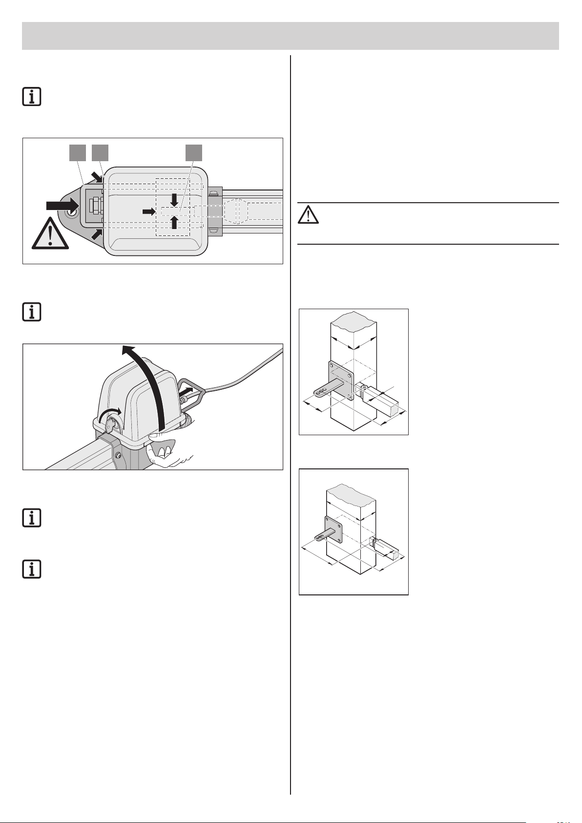
Locking the drive
1. Proceed in reverse order of emergency unlock.
NOTE!
The emergency release bracket (11) must be almost in contact
with the housing (12). If the drive is not completely unlocked,
it will damage the motor (7).
11 12 13
Removing cover
NOTE!
Remove the cover only with the control unit disconnected
from the power and locked to prevent reactivation.
Steel posts
Note the thickness of the post.
The fitting can be welded or bolted directly to steel posts.
Brick or concrete pillars
When attaching the fitting to the brick pillar, ensure that the holes are not
too close to the edge of the pillar. The distance may vary depending on the
type of plug. The plug manufacturer will provide recommended distances.
Timber posts
The included fitting can be used, because the forces are not excessively
large.
If the included fitting cannot be used with your gate, contact your dealer for
special fittings (e.g. wood post fitting).
NOTE!
After installation of fittings do not do any more welding or
grinding. Residues of such work will result in rapid corrosion
of fittings.
Examples for A/B dimensions
1. Small post
Assumed:
Steel post 100 mm x 100 mm
desired opening angle min. 90°
wing length 1.5 m
Measured:
A = 80 mm
B = 110 mm
17
According to table
A = 80 mm
B = 120 mm
B = 110
Opening angle = max. 94°
A = 80
100
100
Installation of ttings
NOTE!
The strength of the included fittings is designed for the drive
(twist 200). If other fittings are used, the warranty will not
apply.
NOTE!
If the B dimension is smaller than the smallest B dimension in
the table, install a spacer plate under the post fitting to ensure
that the B dimension is at least 100 mm (see A/B dimension
table).
¾ Cover or remove the drive when welding fittings to posts or gate wing
to prevent damage from sparks or welding beads.
¾ Attach fitting to thick brick or concrete pillar so the wall plugs cannot
come loose during operation. Adhesive-bonded anchors, with which
a threaded pin is cemented to the brickwork without tension, are more
suitable than steel and plastic expanding plugs.
¾ Clearances between the gate wing and post or gate wing and drive
must be maintained in accordance with the applicable standards.
2. Long post
215
A = 225
100
78
B = 165
Assumed:
Concrete pillar 215 mm x 100 mm
desired opening angle min. 95°
wing length 2.5 m
Measured:
A = 225 mm
B = 165 mm
According to table
A = 220 mm
B = 160 mm
Opening angle = max. 91°
– 10
Loading…
- Главная
- Каталог
- Автоматика
- SOMMER
- Приводы для распашных ворот
-
Комплект Twist 200E
72 779 руб.
Монтаж:
| За комплект | 6435 руб. |
| *В стоимость монтажа не входит установка зубчатой рейки на объекте и подведение питания |
Производитель: SOMMER (Германия)
Комплект для автоматизации распашных ворот до 600 кг шириной до 5 м. В комплект входит блок управления со встроенным приемником, крепёжные кронштейны. В комплект поставки входит 1 пульт дистанционного управления.
Комплект для распашных ворот для проёма шириной до 5 метров.
Состав комплекта:
— Электропривод (2 шт),
— Блок управления выносной,
— Комплект крепежных кронштейнов,
— Встроенный радиоприёмник,
— Пульт дистанционного управления двухканальный.
Отличительные особенности:
— Легкая аварийная разблокировка в любом положении,
— Плавный и бесшумный ход,
— Автоматическое закрытие,
— Реакция на препятствие,
— Работа в условиях низких температур (от -30°С).
Технические характеристики
| Максимальная ширина ворот ( при весе 400 кг) | 5000 мм |
| Максимальный вес ворот (при ширине ворот 3 м) | 600 кг |
| Питание | 230 В / 50 Гц |
| Ход перемещения | 390 мм |
| Скорость максимальная при толкании | 16,5 мм/с |
| Рабочий диапазон температур | -30°С +70°С |
| Степень защиты блока управления | IP65 |
| Степень защиты привода | IP44 |
| Уровень шума | 47 дБ |
| Максимальная потребляемая мощность для одной створки | 140 Вт |
| Потребляемая мощность в режиме экономии энергии | 3 Вт |
| Максимальный потребляемый ток для одной створки | 0,8 А |
| Количество прописываемых пультов в памяти приёмника | 112 |
| Продолжительность включения | S3=40% |
| Номинальный крутящий момент для одной створки | 660 Н |
| Максимальное усилие тяги и нажатия одной створки | 2000 Н |
| Наклон ворот | 10% |
Остались вопросы? Закажите консультацию
Нажмите для связи через WhatsApp
Хорошее руководство по эксплуатации
Законодательство обязывает продавца передать покупателю, вместе с товаром, руководство по эксплуатации Sommer twist 200 E. Отсутствие инструкции либо неправильная информация, переданная потребителю, составляют основание для рекламации в связи с несоответствием устройства с договором. В законодательстве допускается предоставлении руководства в другой, чем бумажная форме, что, в последнее время, часто используется, предоставляя графическую или электронную форму инструкции Sommer twist 200 E или обучающее видео для пользователей. Условием остается четкая и понятная форма.
Что такое руководство?
Слово происходит от латинского «instructio», тоесть привести в порядок. Следовательно в инструкции Sommer twist 200 E можно найти описание этапов поведения. Цель инструкции заключается в облегчении запуска, использования оборудования либо выполнения определенной деятельности. Инструкция является набором информации о предмете/услуге, подсказкой.
К сожалению немного пользователей находит время для чтения инструкций Sommer twist 200 E, и хорошая инструкция позволяет не только узнать ряд дополнительных функций приобретенного устройства, но и позволяет избежать возникновения большинства поломок.
Из чего должно состоять идеальное руководство по эксплуатации?
Прежде всего в инструкции Sommer twist 200 E должна находится:
— информация относительно технических данных устройства Sommer twist 200 E
— название производителя и год производства оборудования Sommer twist 200 E
— правила обслуживания, настройки и ухода за оборудованием Sommer twist 200 E
— знаки безопасности и сертификаты, подтверждающие соответствие стандартам
Почему мы не читаем инструкций?
Как правило из-за нехватки времени и уверенности в отдельных функциональностях приобретенных устройств. К сожалению само подсоединение и запуск Sommer twist 200 E это слишком мало. Инструкция заключает ряд отдельных указаний, касающихся функциональности, принципов безопасности, способов ухода (даже то, какие средства стоит использовать), возможных поломок Sommer twist 200 E и способов решения проблем, возникающих во время использования. И наконец то, в инструкции можно найти адресные данные сайта Sommer, в случае отсутствия эффективности предлагаемых решений. Сейчас очень большой популярностью пользуются инструкции в форме интересных анимаций или видео материалов, которое лучше, чем брошюра воспринимаются пользователем. Такой вид инструкции позволяет пользователю просмотреть весь фильм, не пропуская спецификацию и сложные технические описания Sommer twist 200 E, как это часто бывает в случае бумажной версии.
Почему стоит читать инструкции?
Прежде всего здесь мы найдем ответы касательно конструкции, возможностей устройства Sommer twist 200 E, использования отдельных аксессуаров и ряд информации, позволяющей вполне использовать все функции и упрощения.
После удачной покупки оборудования/устройства стоит посвятить несколько минут для ознакомления с каждой частью инструкции Sommer twist 200 E. Сейчас их старательно готовят или переводят, чтобы они были не только понятными для пользователя, но и чтобы выполняли свою основную информационно-поддерживающую функцию.
- Home
- Инструкции
- Автоматика для ворот
- SOMMER
- TWIST 200 E
| SOMMER TWIST 200 E инструкция | |
|---|---|
| Тип инструкции: | Руководство по установке и использованию |
| Категория: | Автоматика для ворот SOMMER |
| Язык: | Русский |
| Размер: | 1.5 Mb |
| Формат файла: | |
| Дата добавления: | 13.06.2013 |
Похожие записи
SOMMER TWIST 200 — Инструкция по эксплуатации
Автоматика для ворот
SOMMER TWIST 200 EL — Инструкция по эксплуатации и монтажу
Автоматика для ворот
SOMMER TWIST 350 — Инструкция по эксплуатации и монтажу
Автоматика для ворот
SOMMER TWIST XL — Инструкция по эксплуатации и монтажу
Автоматика для ворот
VIPER 200 — Схема подключения
Автосигнализации
FAAC 200 MPS — Инструкция по эксплуатации и монтажу
Автоматика для ворот
A.P.S. 2000 — Инструкция по эксплуатации и монтажу
Автосигнализации
ФАНТОМ 2000 — Инструкция по эксплуатации и монтажу
Автоматика для ворот
Комментарии, вопросы, отзывы
Напишите свои комментарии к материалу, вопросы или отзывы по оборудованию
Кто вы? человек робот