
Ultra-Mini Dome
FD8136
Network Camera
User’s Manual
1MP • Stylish Design • PoE
Rev. 1.0

VIVOTEK
Table of Contents
Overview……………………………………………………………………………………………………………………… 4
Revision History �������������������������������������������������������������������������������������������������������������������������������������� 4
Read Before Use ������������������������������������������������������������������������������������������������������������������������������������� 5
Package Contents ����������������������������������������������������������������������������������������������������������������������������������� 5
Symbols and Statements in this Document ��������������������������������������������������������������������������������������������� 5
Physical Description �������������������������������������������������������������������������������������������������������������������������������� 6
Installation ����������������������������������������������������������������������������������������������������������������������������������������������� 8
Restoring defaults
Network Deployment ����������������������������������������������������������������������������������������������������������������������������� 10
Software Installation ������������������������������������������������������������������������������������������������������������������������������ 12
Ready to Use ����������������������������������������������������������������������������������������������������������������������������������������� 13
Accessing the Network Camera
Using Web Browsers ����������������������������������������������������������������������������������������������������������������������������� 16
Using RTSP Players ������������������������������������������������������������������������������������������������������������������������������ 19
Using 3GPP-compatible Mobile Devices ����������������������������������������������������������������������������������������������� 20
Using VIVOTEK Recording Software ���������������������������������������������������������������������������������������������������� 21
Main Page ………………………………………………………………………………………………………………. 22
Client Settings ……………………………………………………………………………………………………. 26
Configuration ……………………………………………………………………………………………………. 30
System > General settings �������������������������������������������������������������������������������������������������������������������� 31
System > Homepage layout ����������������������������������������������������������������������������������������������������������������� 33
System > Logs �������������������������������������������������������������������������������������������������������������������������������������� 36
System > Parameters ��������������������������������������������������������������������������������������������������������������������������� 38
System > Maintenance �������������������������������������������������������������������������������������������������������������������������� 39
Media > Image ������������������������������������������������������������������������������������������������������������������������������������ 43
Media > Video ��������������������������������������������������������������������������������������������������������������������������������������� 49
Media > Video ��������������������������������������������������������������������������������������������������������������������������������������� 50
Media > Audio���������������������������������������������������������������������������������������������������������������������������������������� 54
Network > General settings ������������������������������������������������������������������������������������������������������������������� 55
Network > Streaming protocols ����������������������������������������������������������������������������������������������������������� 62
Network > SNMP
Security > User Account ������������������������������������������������������������������������������������������������������������������������ 72
Security > HTTPS
Security > Access List ������������������������������������������������������������������������������������������������������������������������� 78
PTZ > PTZ settings ������������������������������������������������������������������������������������������������������������������������������� 83
Event > Event settings��������������������������������������������������������������������������������������������������������������������������� 87
Applications > Motion detection����������������������������������������������������������������������������������������������������������� 100
Applications > Digital Input ������������������������������������������������������������������������������������������������������������������ 103
Applications > Tampering detection ���������������������������������������������������������������������������������������������������� 103
Recording > Recording settings ��������������������������������������������������������������������������������������������������������� 104
Local storage > SD card management ������������������������������������������������������������������������������������������������ 109
Local storage > Content management ������������������������������������������������������������������������������������������������ 11 0
Appendix …………………………………………………………………………………………………………….. 113
URL Commands for the Network Camera ������������������������������������������������������������������������������������������� 113
(Simple Network Management Protocol) ������������������������������������������������������71
(Hypertext Transfer Protocol over SSL)
������������������������������������������������ 73
9
16
2 — User’s Manual

VIVOTEK
Technical Specications ���������������������������������������������������������������������������������������������������������������������������202
Technology License Notice �����������������������������������������������������������������������������������������������������������������������203
Electromagnetic Compatibility (EMC) �������������������������������������������������������������������������������������������������������204
User’s Manual — 3

VIVOTEK
Overview
VIVOTEK FD8136 is the world’s smallest network xed dome camera. With installation as easy
as one-two-three and Power over Ethernet (PoE) functionality, setup time is completed in less
than 120 seconds, making installation quick and easy�
The FD8136 features a megapixel sensor enabling viewing resolution of 1280×800 at 30 fps,
and also supports the industry-standard H�264 compression technology, drastically reducing
le sizes and conserving valuable network bandwidth. With MPEG-4 and MJPEG compatibility
also included, video streams can also be transmitted in any of these formats for versatile
applications�
Designed with selectable focal lengths, FD8136 can be used in various environments, including but not
limited to ofces, elevators, campus, chain stores, boutique stores and health care facilities. At the size of
only 90 mm in diameter, VIVOTEK FD8136 is truly an all-in-one surveillance solution that meets a wide
variety of needs for indoor surveillance� The package also includes VIVOTEK’s 32-channel recording
software� With all this and more, the FD8136 is the ideal solution for your surveillance needs�
Revision History
■ Rev. 1.0: Initial release
4 — User’s Manual
VIVOTEK
Read Before Use
The use of surveillance devices may be prohibited by law in your country� The Network Camera
is not only a high-performance web-ready camera but can also be part of a exible surveillance
system� It is the user’s responsibility to ensure that the operation of such devices is legal before
installing this unit for its intended use�
It is important to first verify that all contents received are complete according to the Package
Contents listed below� Take note of the warnings in the Quick Installation Guide before the Network
Camera is installed; then carefully read and follow the instructions in the Installation chapter to
avoid damage due to faulty assembly and installation� This also ensures the product is used
properly as intended�
The Network Camera is a network device and its use should be straightforward for those who
have basic networking knowledge� It is designed for various applications including video sharing,
general security/surveillance, etc. The Configuration chapter suggests ways to best utilize the
Network Camera and ensure proper operations� For creative and professional developers, the URL
Commands of the Network Camera section serves as a helpful reference to customizing existing
homepages or integrating with the current web server�
Package Contents
■ FD8136
■ Screws / Plastic Anchors
■ Alignment sticker
■ Quick Installation Guide
■ Mount bracket
Symbols and Statements in this Document
INFORMATION: provides important messages or advices that might help prevent
inconvenient or problem situations�
NOTE: Notices provide guidance or advices that are related to the functional integrity of
the machine�
Tips: Tips are useful information that helps enhance or facilitate an installation, function,
or process�
WARNING: or IMPORTANT: These statements indicate situations that can be dangerous
or hazardous to the machine or you.
Electrical Hazard: This statement appears when high voltage electrical hazards might
occur to an operator�
User’s Manual — 5

VIVOTEK
Physical Description
Outer View
Release tab
Leave the slide cover in place if you route cables through the bottom
and then through a hole on the ceiling or wall�
Inner View
Side View
RJ-45 Socket
Slide cover
Lens
Digital input
DI+ DI-
Max� is 40V�
LEDs
MicroSD/SDHC
card slot
Tilt adjustment
screw
Reset button
Screw slot
6 — User’s Manual
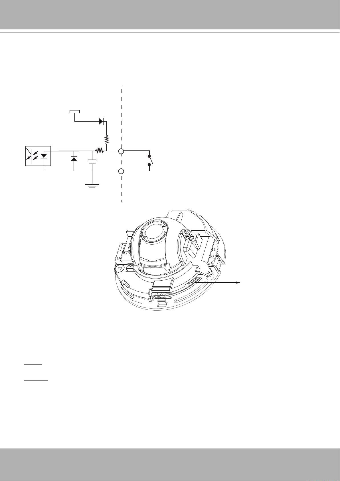
Digital Input Diagram
Please refer to the following illustration for the connection method�
Max. voltage: 40V
3.3V
DI+
Digital input
DI-
DI-: Ground
VIVOTEK
Hardware Reset
Reset Button
The reset button is used to reset the system or restore the factory default settings� Sometimes
resetting the system can return the camera to normal operation� If the system problems remain
after reset, restore the factory settings and install again�
Reset: Press and release the reset button. Wait for the Network Camera to reboot.
Restore: Press and hold the recessed reset button until the status LED rapidly blinks. Note that
all settings will be restored to factory default� Upon successful restore, the status LED will blink
green and red during normal operation�
Micro SD/SDHC Card Capacity
This network camera is compliant with Micro SD/SDHC 16GB / 8GB and other preceding
standard SD cards�
User’s Manual — 7
VIVOTEK
Installation
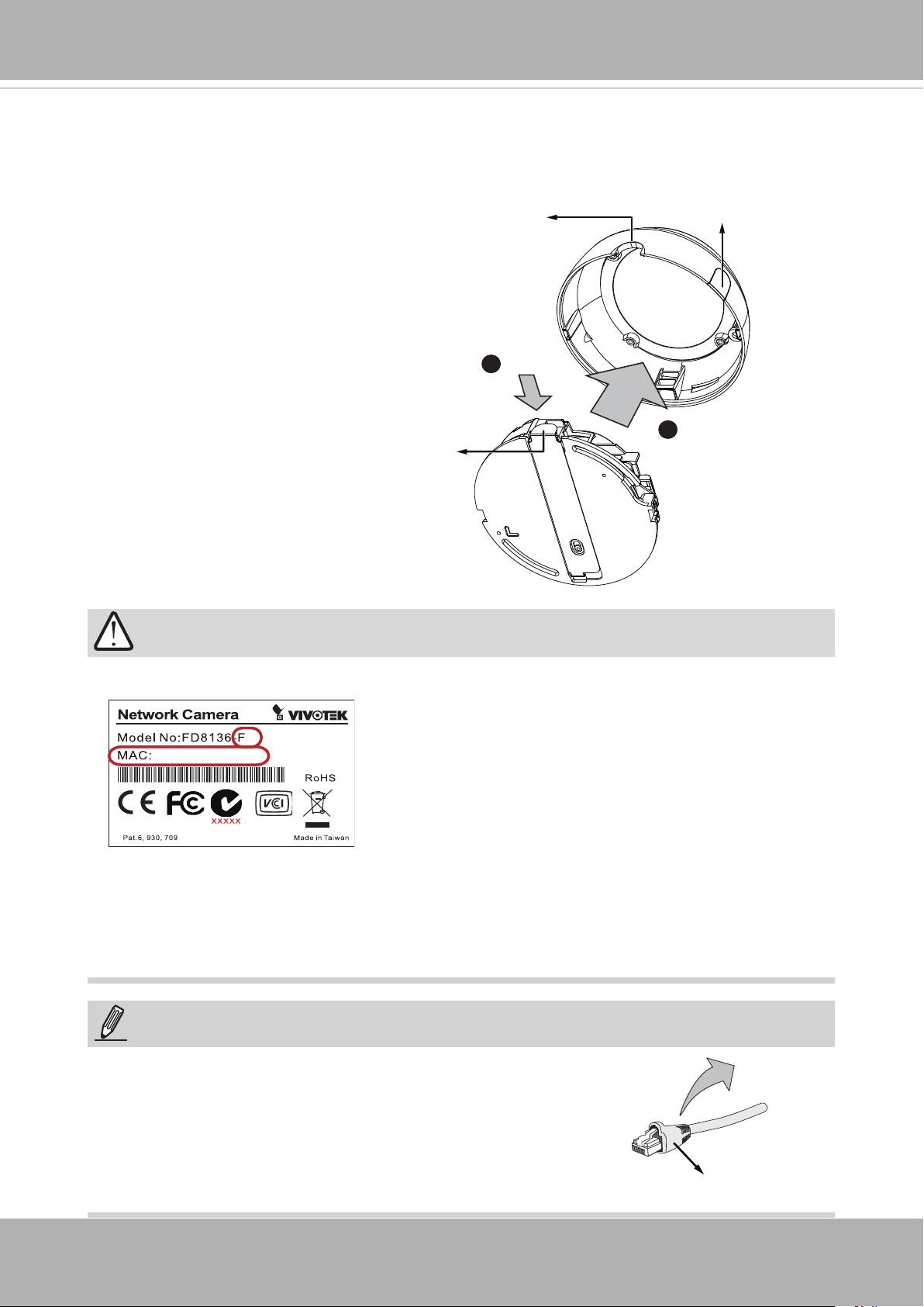
Removing Dome Cover
1� Use one hand to hold the camera
bottom and another hand to hold the
dome cover� Press the release button�
2� Remove the dome cover�
3� Remove the slide cover if you want to
route cables from the side of camera
instead of a hole on the ceiling or wall�
Release tab
IMPORTANT!
Semi-circular
cut-out
1
Slide cover
2
1� Record the MAC address before installing the camera�
2. You can check the model name sufx for the type of lens mounted on your camera. The
applicable lens can be:
F2: 2.5mm; F3: 3.6mm; F6: 6mm; F8: 8mm; F12: 12mm. The shorter the focal length,
the wider the view�
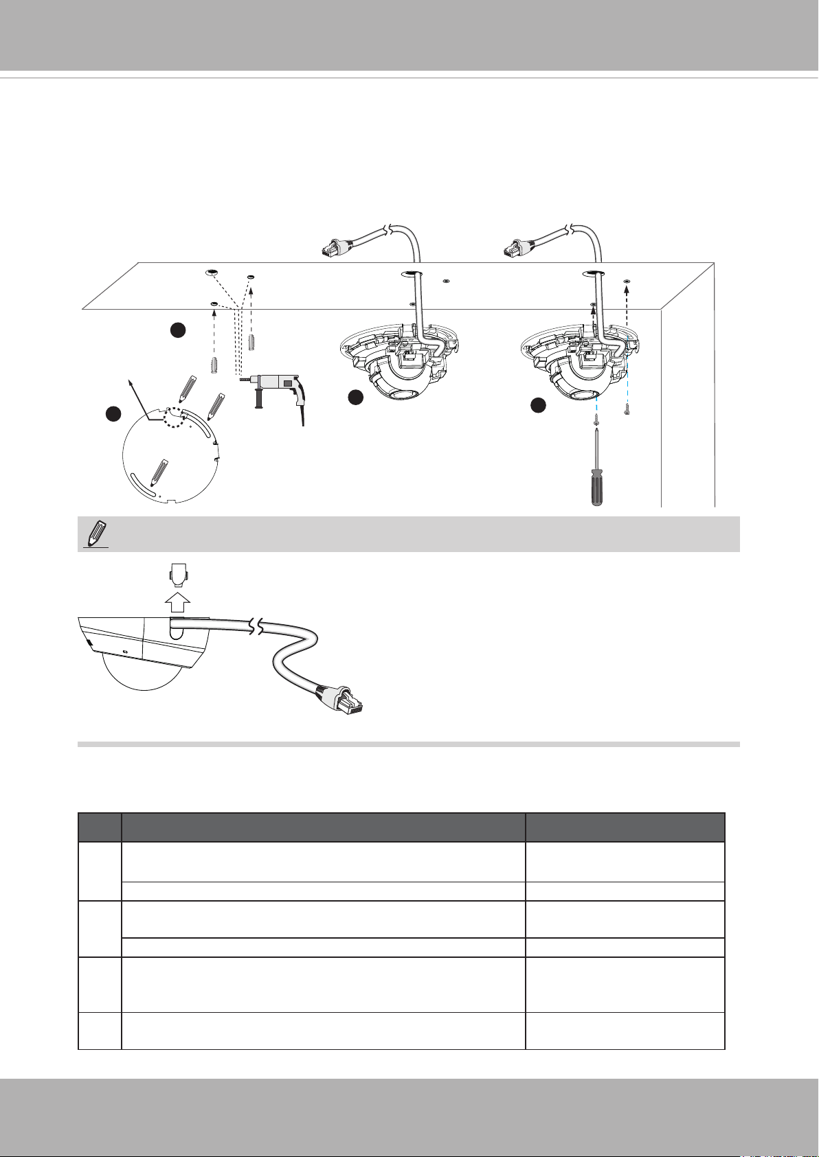
NOTE:
It is recommended to use an Ethernet cable that comes without
the strain relief boot� You can remove the boot if your cable
comes with one�
8 — User’s Manual
Strain relief boot
VIVOTEK
Mounting the Network Camera — Ceiling or Wall Mount
1� Use the curved slots on the camera as a template to mark where holes will be drilled on
the ceiling� Drill two holes into the ceiling; and hammer in the plastic anchors�
2� Drill another hole if you want to route cables through the ceiling or wall�
3� Connect and route an Ethernet cable through the ceiling or wall�
4� Attach the Network Camera to the ceiling using two included screws�
2
Routing hole
position
1
NOTE:
LED Denitions
3
4
1� Do not completely tighten the mounting screws
in the screw slots yet� You may need to turn the
camera left or right for a best shooting direction
later�
2� The camera can only be powered by PoE� There
is no DC or AC input connector�
3� As shown on the left, you may also route cable
from the side�
Item LED Status Description
1 Steady Red Power on and system boot-
ing
Red LED off Power off
2 Steady Red + blinking Green every 1 sec� (Green LED on
for 1 sec and off for another)
Steady Red + Green LED off Network disconnected
3 Blinking Red every 0�15 sec� + Blinking Green every 1 sec�
(Red LED on for 0�15 sec� and Green LED on for 1 sec� and
off for another)
4 Blinking Red every 0�15 sec� + blinking Green every 0�15
sec�
Network heartbeat
Upgrading rmware
Restoring defaults
User’s Manual — 9
VIVOTEK
Network Deployment
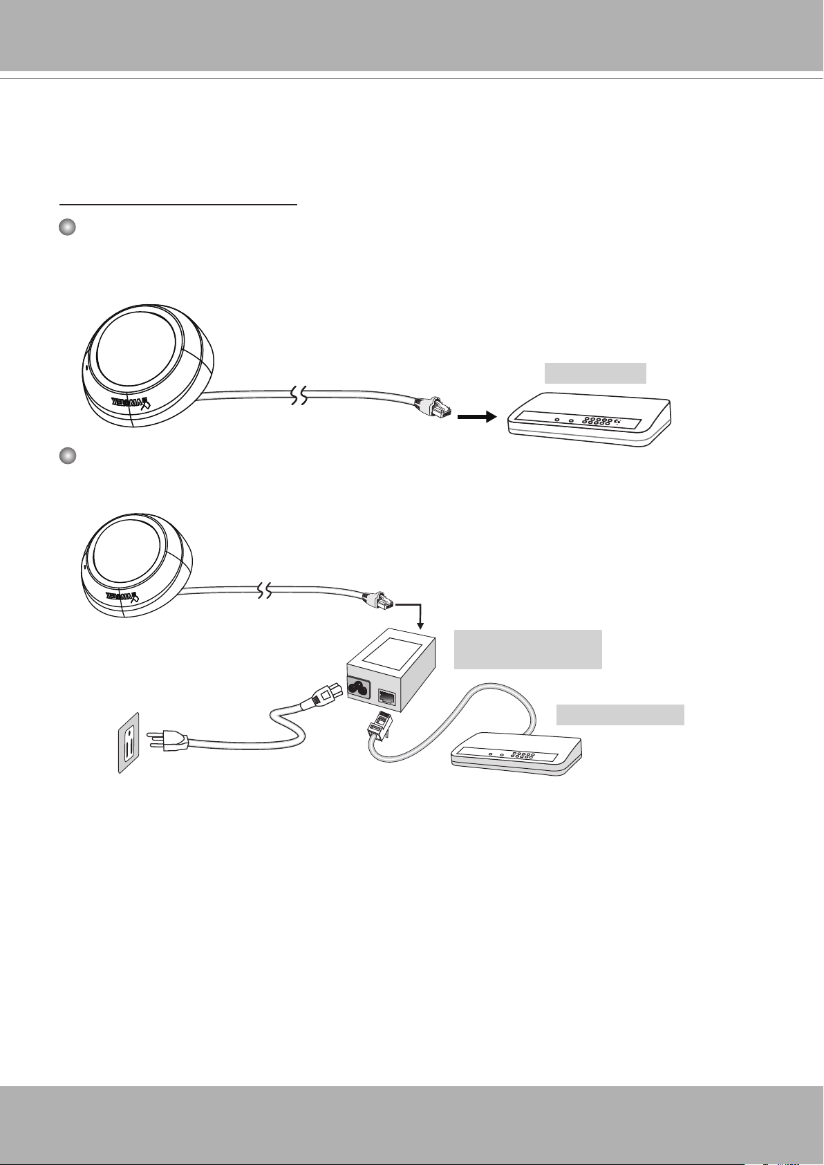
General Connection (without PoE)
Power over Ethernet (PoE)
When using a PoE-enabled switch
This Network Camera is PoE-compliant, allowing transmission of power and data via a single
Ethernet cable� Follow the below illustration to connect the camera to a PoE-enabled switch
via Ethernet cable�
PoE Switch
L
I
N
POW
ER
C
O
LL
I
S
ION
1
K
RE
CEIVE
PARTITIO
2
3
N
4
5
When using a non-PoE switch
Use a PoE power injector (optional) to connect between the Network Camera and a non-PoE
switch�
PoE Power Injector
(optional)
Non-PoE Switch
L
I
N
POW
ER
C
O
LL
I
S
ION
K
RECEIVE
1
PARTITIO
2
N
3
4
5
10 — User’s Manual
VIVOTEK
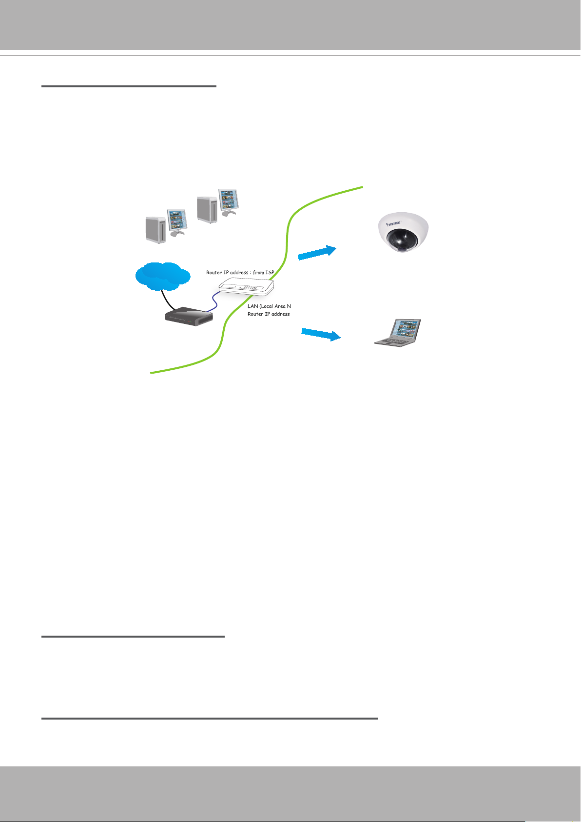
Internet connection via a router
Before setting up the Network Camera over the Internet, make sure you have a router and follow
the steps below�
1� Connect your Network Camera behind a router, the Internet environment is illustrated below�
Regarding how to obtain your IP address, please refer to Software Installation on page 12 for
details�
IP address : 192.168.0.3
Subnet mask : 255.255.255.0
Default router : 192.168.0.1
IP address : 192.168.0.2
Subnet mask : 255.255.255.0
Default router : 192.168.0.1
Internet
Cable or DSL Modem
WAN (Wide Area Network )
Router IP address : from ISP
LINK
POWER
COLLISION
RECEIVE
1
2
PARTITION
3
4
5
LAN (Local Area Network)
Router IP address : 192.168.0.1
2� In this case, if the Local Area Network (LAN) IP address of your Network Camera is
192�168�0�3, please forward the following ports for the Network Camera on the router�
■ HTTP port: default is 80
■ RTSP port: default is 554
■ RTP port for audio: default is 5558
■ RTCP port for audio: default is 5559
■ RTP port for video: default is 5556
■ RTCP port for video: default is 5557
If you have changed the port numbers on the Network page, please open the ports
accordingly on your router� For information on how to forward ports on the router, please refer
to your router’s user’s manual�
3� Find out the public IP address of your router provided by your ISP (Internet Service Provider)�
Use the public IP and the secondary HTTP port to access the Network Camera from the
Internet� Please refer to Network Type on page 55 for details�
Internet connection with static IP
Choose this connection type if you are required to use a static IP for the Network Camera�
Please refer to LAN setting on page 55 for details�
Internet connection via PPPoE (Point-to-Point over Ethernet)
Choose this connection type if you are connected to the Internet via a DSL Line� Please refer to
PPPoE on page 56 for details�
User’s Manual — 11
VIVOTEK
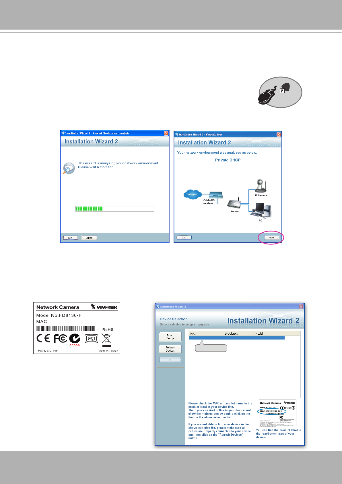
Software Installation
Installation Wizard 2 (IW2), free-bundled software included on the product CD, helps you set up
your Network Camera on the LAN�
IW
1� Install IW2 under the Software Utility directory from the software CD�
Double-click the IW2 shortcut on your desktop to launch the program�
2� The program will conduct an analysis of your network environment�
After your network environment is analyzed, please click Next to continue the program�
2
Installation
Wizard 2
3� The program will search for all VIVOTEK network devices on the same LAN�
4� After a brief search, the installer window will prompt� Click on the MAC and model name
that matches the one printed on the product label� You can then double-click on the address to
open a management session with the Network Camera�
2
0002D10766AD
00-02-D1-73-02-02 192.168.5.151 FD8136
0002D1730202
12 — User’s Manual
VIVOTEK
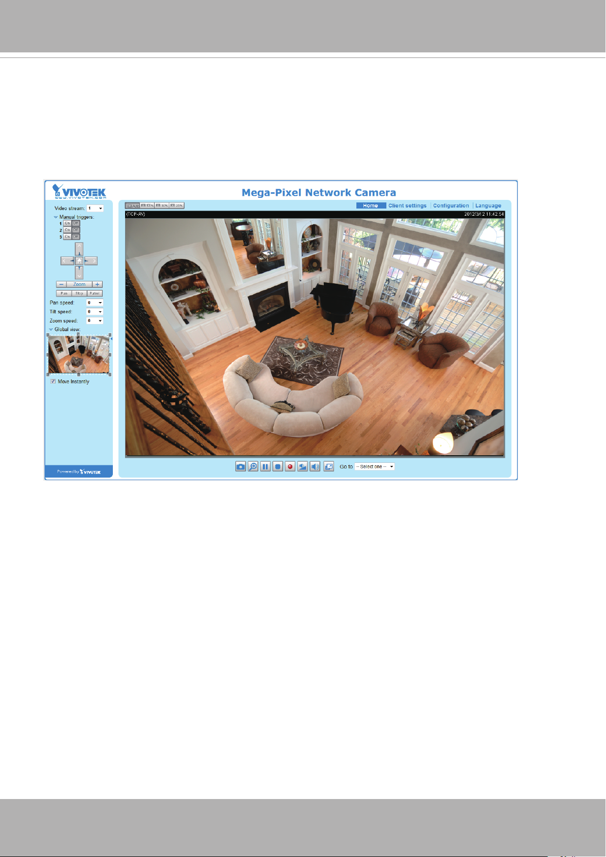
Ready to Use
1� A browser session with the Network Camera should prompt as shown below�
2� You should be able to see live video from your camera� You may also install the 32-channel
recording software from the software CD in a deployment consisting of multiple cameras� For
its installation details, please refer to its related documents�
User’s Manual — 13
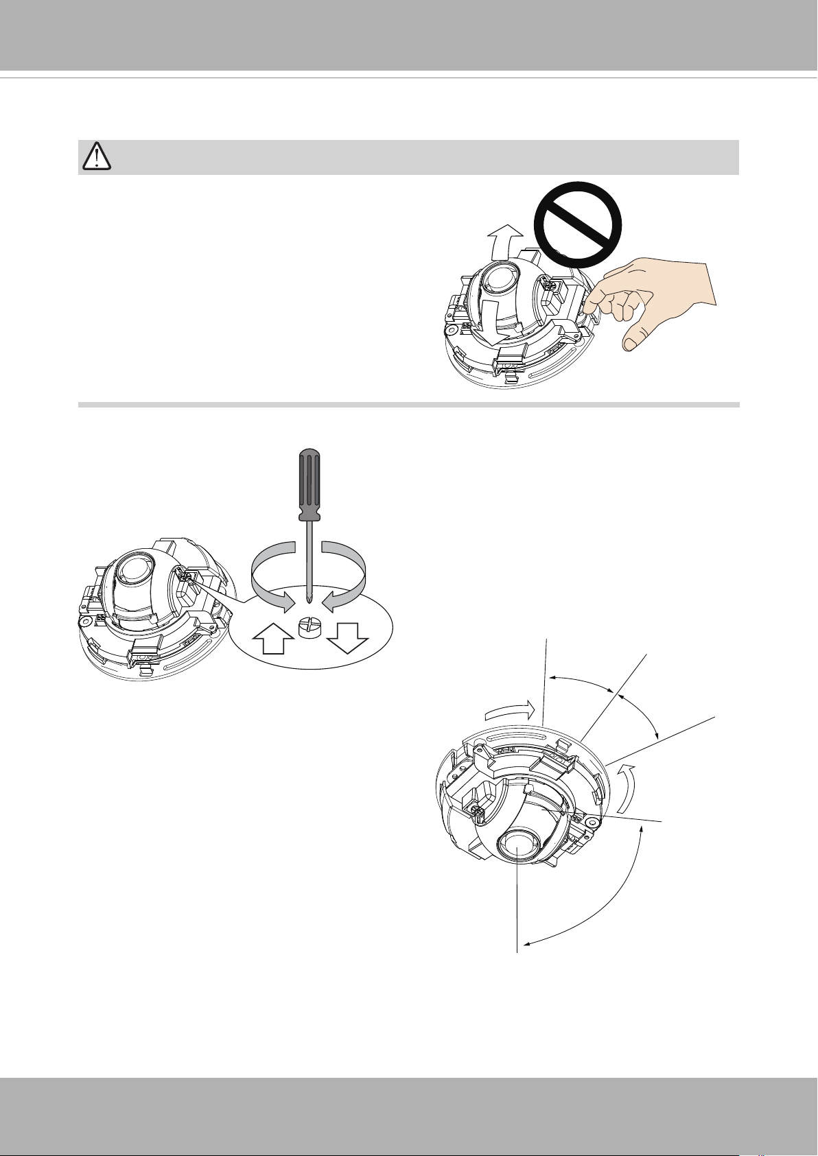
VIVOTEK
Adjusting the Lens
WARNING!
Do not use your hands to tune the lens module’s
tilt angle� Doing so will damage the delicate tilt
mechanism�
Lens UP Lens DOWN
3� Tighten the camera’s mounting screws
after you change the horizontal shooting
direction�
1� There is a tilt adjustment screw near the
lens module� Use a #0, #1, or #2 Phillips
screwdriver to turn the screw and the lens
will move upwards or downwards�
2. You may also tune the camera’s horizontal
orientation by turning it along its curved
screw slots�
25°
25°
14 — User’s Manual
57°
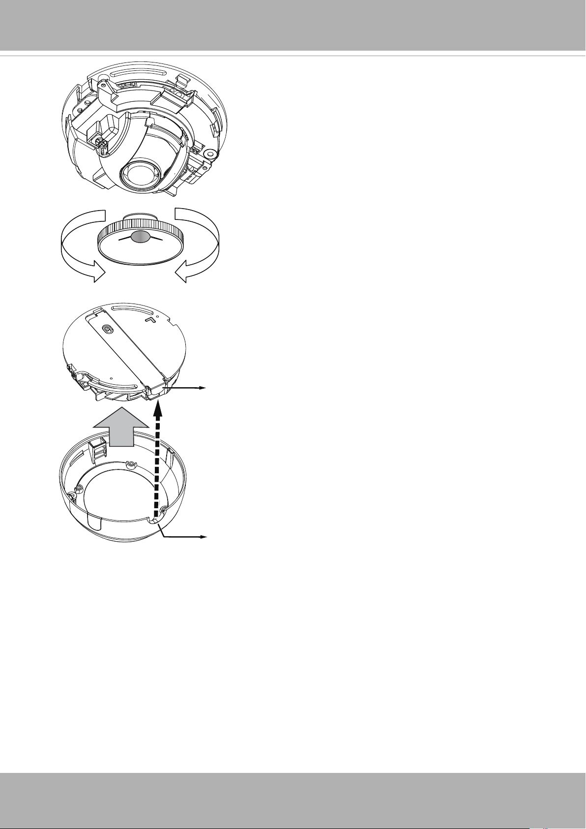
VIVOTEK
4� With a live video feed, you can place the included
focus adjustment tool carefully on the lens, and
use it to turn the lens clockwise or counterclockwise to adjust to the best image focus�
You may try tuning the focus slightly closer due to
the concern that focus might be changed when the
dome cover is installed�
5� Use a piece of clean cotton cloth to hold and and
install the dome cover�
6� Install dome cover by aligning the semi-circular
cut-out with the release tab� Press on both ends
of the dome cover for it to snap into place� A
«Click» sound should be heard when it is properly
installed�
Release
tab
Semi-circular
cut-out
User’s Manual — 15
VIVOTEK
Accessing the Network Camera
This chapter explains how to access the Network Camera through web browsers, RTSP players,
3GPP-compatible mobile devices, and VIVOTEK recording software�
Using Web Browsers
Use Installation Wizard 2 (IW2) to access the Network Cameras on LAN.
If your network environment is not a LAN, follow these steps to access the Netwotk Camera:
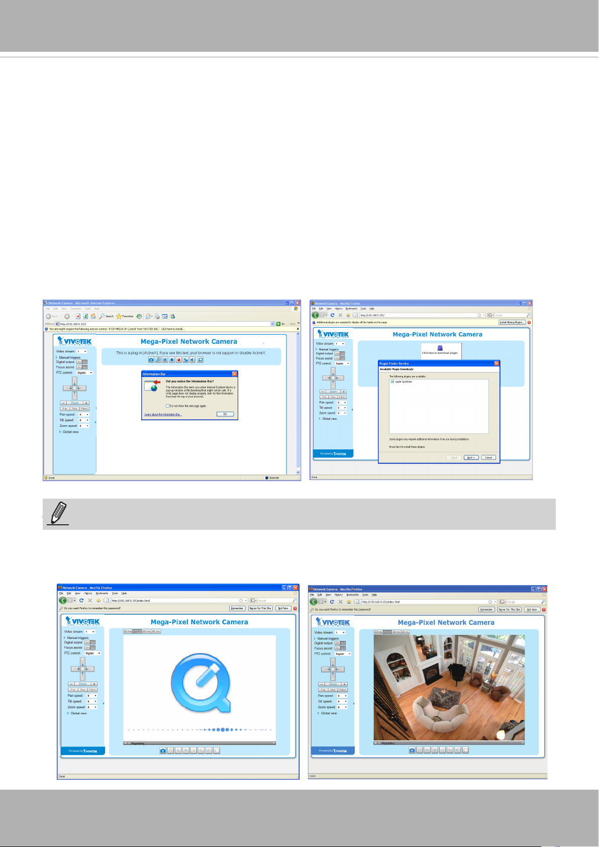
1� Launch your web browser (e�g�, Microsoft® Internet Explorer, Mozilla Firefox, or Netscape).
2. Enter the IP address of the Network Camera in the address eld. Press Enter�
3� The live video will be displayed in your web browser�
4. If it is the rst time installing the VIVOTEK network camera, an information bar will pop up as
shown below� Follow the instructions to install the required plug-in on your computer�
NOTE
► For Mozilla Firefox or Netscape users, your browser will use Quick Time to stream the live
16 — User’s Manual
NOTE:
video. If you don’t have Quick Time on your computer, please download it rst, then launch
the web browser�
VIVOTEK
► By default, the Network Camera is not password-protected. To prevent unauthorized access,
it is highly recommended to set a password for the Network Camera�
For more information about how to enable password protection, please refer to Security on
page 72�
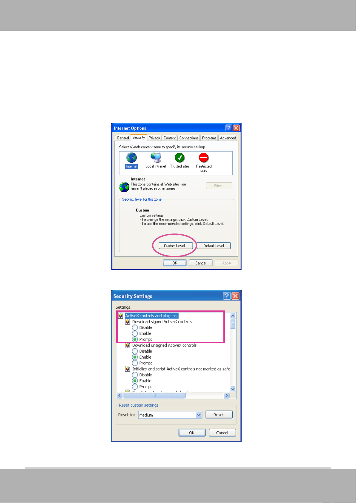
► If you see a dialog box indicating that your security settings prohibit running ActiveX®
Controls, please enable the ActiveX® Controls for your browser�
1� Choose Tools > Internet Options > Security > Custom Level�
2. Look for Download signed ActiveX® controls; select Enable or Prompt� Click OK�
3. Refresh your web browser, then install the ActiveX® control� Follow the instructions to
complete installation�
User’s Manual — 17

VIVOTEK
IMPORTANT!
Currently the Network Camera utilizes 32-bit ActiveX plugin. You CAN NOT open a
•
management/view session with the camera using a 64-bit IE browser�
If you encounter this problem, try execute the Iexplore.exe program from C:\
•
Windows\SysWOW64. A 32-bit version of IE browser will be installed.
On Windows 7, the 32-bit explorer browser can be accessed from here:
•
C:\Program Files (x86)\Internet Explorer\iexplore.exe
18 — User’s Manual
VIVOTEK
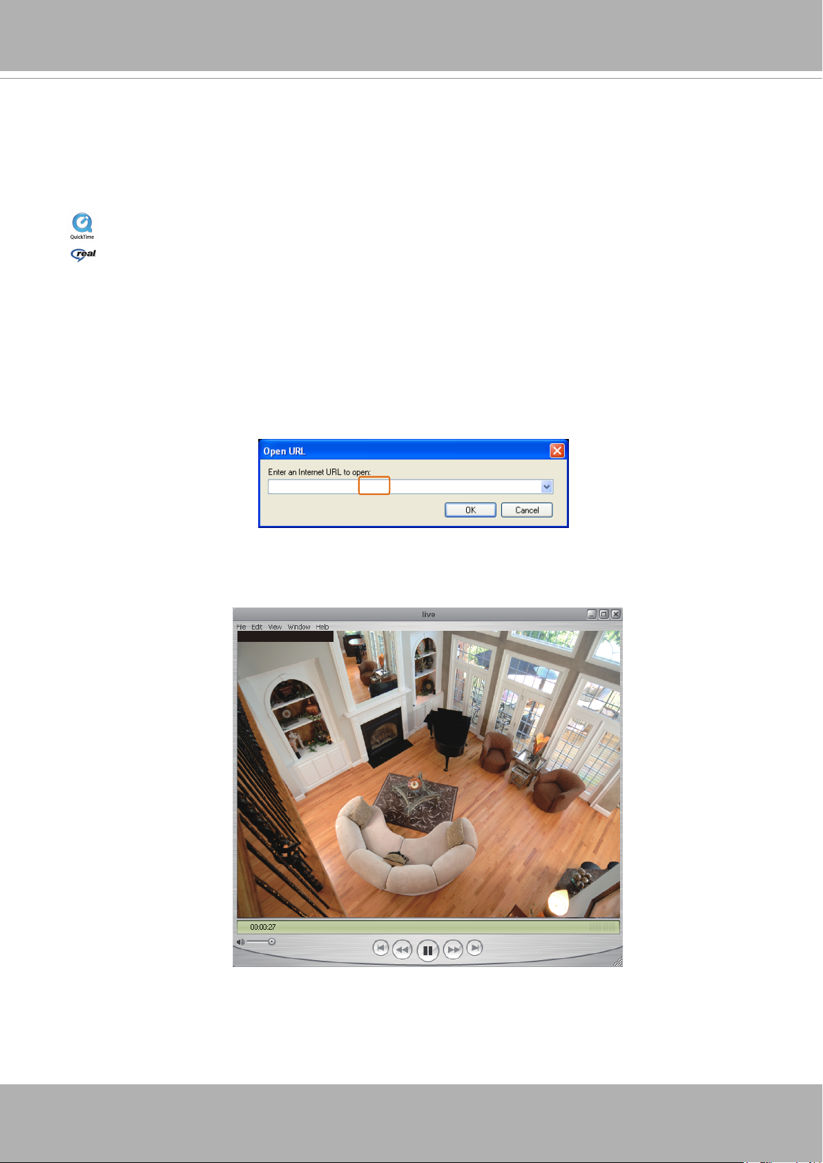
Using RTSP Players
To view the MPEG-4 streaming media using RTSP players, you can use one of the following
players that support RTSP streaming�
Quick Time Player
Real Player
VLC media player
1� Launch the RTSP player�
mpegable Player
2� Choose File > Open URL� A URL dialog box will pop up�
3. The address format is rtsp://<ip address>:<rtsp port>/<RTSP streaming access name for
pvPlayer
stream1 or stream2>
As most ISPs and players only allow RTSP streaming through port number 554, please set the
RTSP port to 554� For more information, please refer to RTSP Streaming on page 63�
For example:
rtsp://192.168.5.151:554/live.sdp
4� The live video will be displayed in your player�
For more information on how to configure the RTSP access name, please refer to RTSP
Streaming on page 63 for details�
Video 16:38:01 2012/01/25
User’s Manual — 19
VIVOTEK
Using 3GPP-compatible Mobile Devices
To view the streaming media through 3GPP-compatible mobile devices, make sure the Network
Camera can be accessed over the Internet� For more information on how to set up the Network
Camera over the Internet, please refer to Setup the Network Camera over the Internet on page
10�
To utilize this feature, please check the following settings on your Network Camera:
1� Because most players on 3GPP mobile phones do not support RTSP authentication, make
sure the authentication mode of RTSP streaming is set to disable�
For more information, please refer to RTSP Streaming on page 63�
2. As the the bandwidth on 3G networks is limited, you will not be able to use a large video size.
Please set the video and audio streaming parameters as listed below�
For more information, please refer to Stream settings on page 49�
Video Mode MPEG-4
Frame size 176 x 144
Maximum frame rate 5 fps
Intra frame period 1S
Video quality (Constant bit rate) 40kbps
Audio type (GSM-AMR) 12.2kbps
3� As most ISPs and players only allow RTSP streaming through port number 554, please set
the RTSP port to 554� For more information, please refer to RTSP Streaming on page 63�
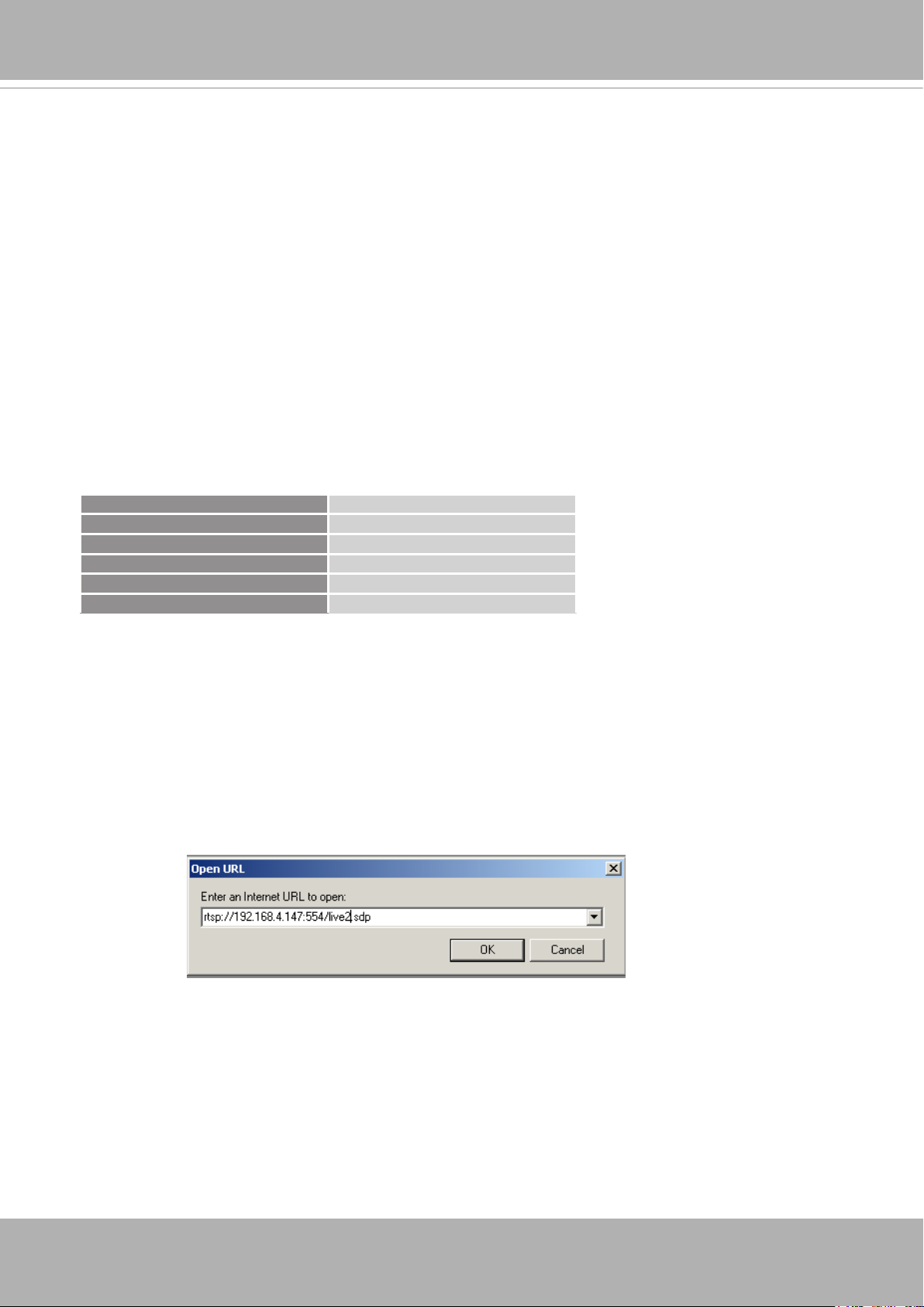
4� Launch the player on the 3GPP-compatible mobile devices (e�g�, Real Player)�
5� Type the following URL commands into the player�
The address format is rtsp://<public ip address of your camera>:<rtsp port>/<RTSP streaming
access name for stream # with small frame size and frame rate>.
For example:
You can configure Stream #2 into the suggested stream settings as listed above for live
viewing on a mobile device�
20 — User’s Manual
VIVOTEK
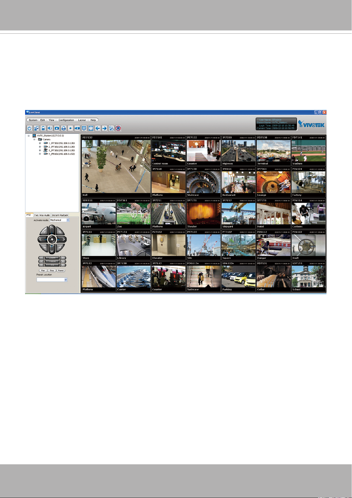
Using VIVOTEK Recording Software
The product software CD also contains an ST7501 recording software, allowing simultaneous
monitoring and video recording for multiple Network Cameras� Please install the recording
software; then launch the program to add the Network Camera to the Channel list� For detailed
information about how to use the recording software, please refer to the user’s manual of the
software or download it from http://www.vivotek.com�
User’s Manual — 21
VIVOTEK
VIVOTEK INC.
Logo
Camera Control
Area
Configuration
Area
Host Name
Resize Buttons
Hide Button
Live View Window
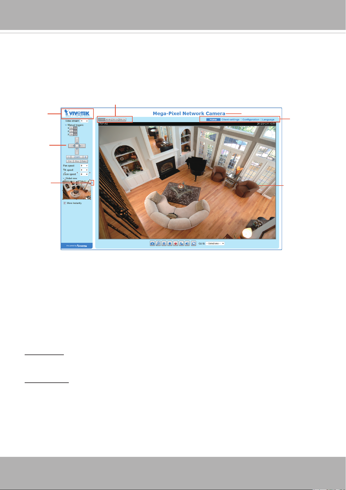
Main Page
This chapter explains the layout of the main page. It is composed of the following sections:
VIVOTEK INC� Logo, Host Name, Camera Control Area, Configuration Area, Menu, and Live
Video Window�
VIVOTEK INC. Logo
Click this logo to visit the VIVOTEK website�
Host Name
The host name can be customized to t your needs. For more information, please refer to System on page 31.
Camera Control Area
Video Stream: This Network Camera supports multiple streams (stream 1 ~ 2) simultaneously. You can
select either one for live viewing� For more information about multiple streams, please refer to page 81
for detailed information�
Manual Trigger: Click to enable/disable an event trigger manually. Please configure an event setting
on Application page before enable this function. A total of 3 event settings can be congured. For more
information about event setting, please refer to page 86� If you want to hide this item on the homepage,
please go to Conguration> System > Homepage Layout > General settings > Customized button
to deselect “show manual trigger button”�
22 — User’s Manual

VIVOTEK
Conguration Area
Client Settings: Click this button to access the client setting page. For more information, please refer to
Client Settings on page 26�
Conguration: Click this button to access the conguration page of the Network Camera. It is suggested
that a password be applied to the Network Camera so that only the administrator can configure the
Network Camera. For more information, please refer to Conguration on page 30.
Language: Click this button to choose a language for the user interface. Language options are available
in: English, Deutsch, Español, Français, Italiano,
日本語
, Português,
簡体中文
, and
繁體中文
� Please
note that you can also change a language on the Conguration page; please refer to page 30.
Hide Button
You can click the hide button to hide the control panel or display the control panel�
Resize Buttons
:
Click the Auto button, the video cell will resize automatically to t the monitor.
Click 100% is to display the original homepage size.
Click 50% is to resize the homepage to 50% of its original size.
Click 25% is to resize the homepage to 25% of its original size.
Live Video Window
■ The following window is displayed when the video mode is set to H.264 / MPEG-4:
H.264 / MPEG-4 Protocol and Media Options
Video Title
Title and Time
Zoom Indicator
Video (TPC-AV)
Video 17:08:56 2011/06/25
x4.0
Video Title: The video title can be congured. For more information, please refer to Video Settings on
page 49�
H�264 / MPEG-4 Protocol and Media Options: The transmission protocol and media options for H.264 /
MPEG-4 video streaming. For further conguration, please refer to Client Settings on page 26.
2011/02/25 17:08:56
Time
Video and Audio Control Buttons
Time: Display the current time. For further conguration, please refer to Media > Image > Genral settings
on page 43�
Title and Time: The video title and time can be stamped on the streaming video. For further conguration,
please refer to Media > Image > General settings on page 43�
User’s Manual — 23
VIVOTEK
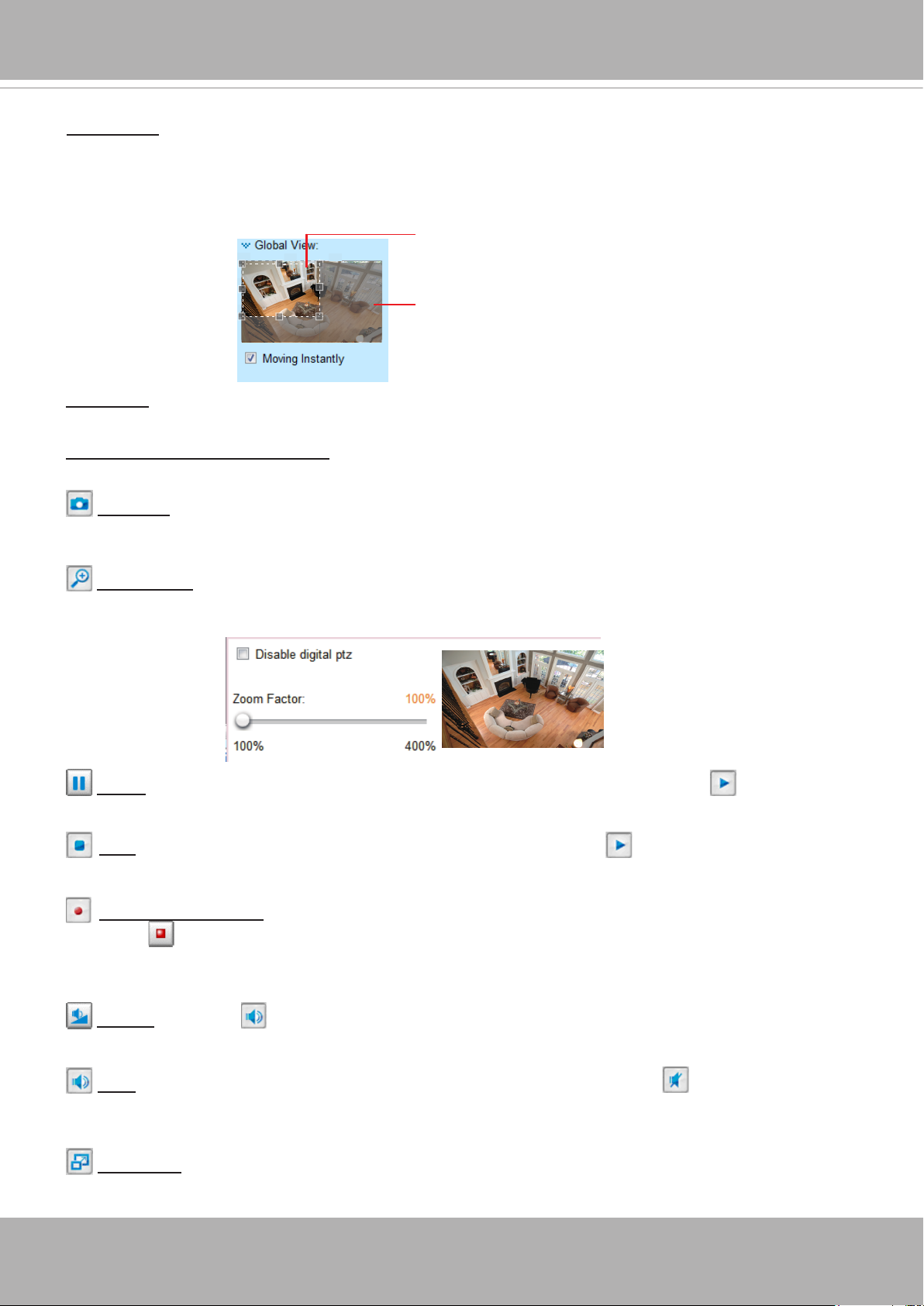
Global View: Click on this item to display the Global View window� The Global View window contains a
full view image (the largest frame size of the captured video) and a oating frame (the viewing region of
the current video stream). The oating frame allows users to control the e-PTZ function (Electronic Pan/
Tilt/Zoom)� For more information about e-PTZ operation, please refer to E-PTZ Operation on page 83�
For more information about how to set up the viewing region of the current video stream, please refer to
page 83�
The viewing region of
the current video
stream
The largest frame size
PTZ Panel: This Network Camera supports both “digital“ (e-PTZ) pan/tilt/zoom control. Please refer to
PTZ settiings on page 83 for detailed information�
Video and Audio Control Buttons: Depending on the Network Camera model and Network Camera
conguration, some buttons may not be available.
Snapshot: Click this button to capture and save still images. The captured images will be displayed
in a pop-up window� Right-click the image and choose Save Picture As to save it in JPEG (*.jpg) or BMP
(*.bmp) format.
Digital Zoom: Click and uncheck “Disable digital zoom” to enable the zoom operation. The navigation
screen indicates the part of the image being magnied. To control the zoom level, drag the slider bar. To
move to a different area you want to magnify, drag the navigation screen�
Pause: Pause the transmission of the streaming media. The button becomes the Resume button
after clicking the Pause button�
Stop: Stop the transmission of the streaming media. Click the Resume button to continue
transmission�
Start MP4 Recording: Click this button to record video clips in MP4 file format to your computer.
Press the Stop MP4 Recording button to end recording� When you exit the web browser, video
recording stops accordingly. To specify the storage destination and le name, please refer to MP4 Saving
Options on page 27 for details�
Volume: When the Mute function is not activated, move the slider bar to adjust the volume on the
local computer�
Mute: Turn off the volume on the local computer� The button becomes the Audio On button after
clicking the Mute button�
Full Screen: Click this button to switch to full screen mode. Press the “Esc” key to switch back to normal
mode�
24 — User’s Manual
VIVOTEK
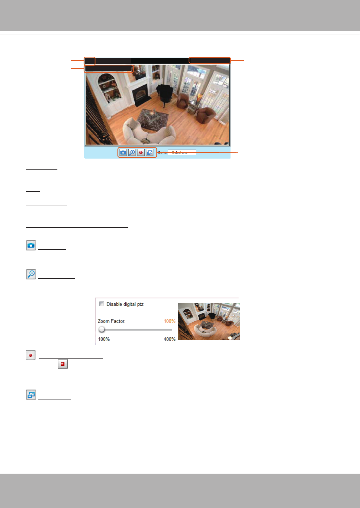
■ The following window is displayed when the video mode is set to MJPEG:
Video Title
Title and Time
Video (HTTP-V)
Video 17:08:56 2011/06/25
Video Title: The video title can be congured. For more information, please refer to Media > Image on
page 43�
Time: Display the current time. For more information, please refer to Media > Image on page 43.
2011/02/25 17:08:56
Time
Video Control Buttons
Title and Time: Video title and time can be stamped on the streaming video. For more information, please
refer to Media > Image on page 43
�
Video and Audio Control Buttons: Depending on the Network Camera model and Network Camera
conguration, some buttons may not be available.
Snapshot: Click this button to capture and save still images. The captured images will be displayed
in a pop-up window� Right-click the image and choose Save Picture As to save it in JPEG (*.jpg) or BMP
(*.bmp) format.
Digital Zoom: Click and uncheck “Disable digital zoom” to enable the zoom operation. The navigation
screen indicates the part of the image being magnied. To control the zoom level, drag the slider bar. To
move to a different area you want to magnify, drag the navigation screen�
Start MP4 Recording: Click this button to record video clips in MP4 file format to your computer.
Press the Stop MP4 Recording button to end recording� When you exit the web browser, video
recording stops accordingly. To specify the storage destination and le name, please refer to MP4 Saving
Options on page 27 for details�
Full Screen: Click this button to switch to full screen mode. Press the “Esc” key to switch back to normal
mode�
User’s Manual — 25
VIVOTEK
Client Settings
This chapter explains how to select the stream transmission mode and saving options on the
local computer� When completed with the settings on this page, click Save on the page bottom
to enable the settings�
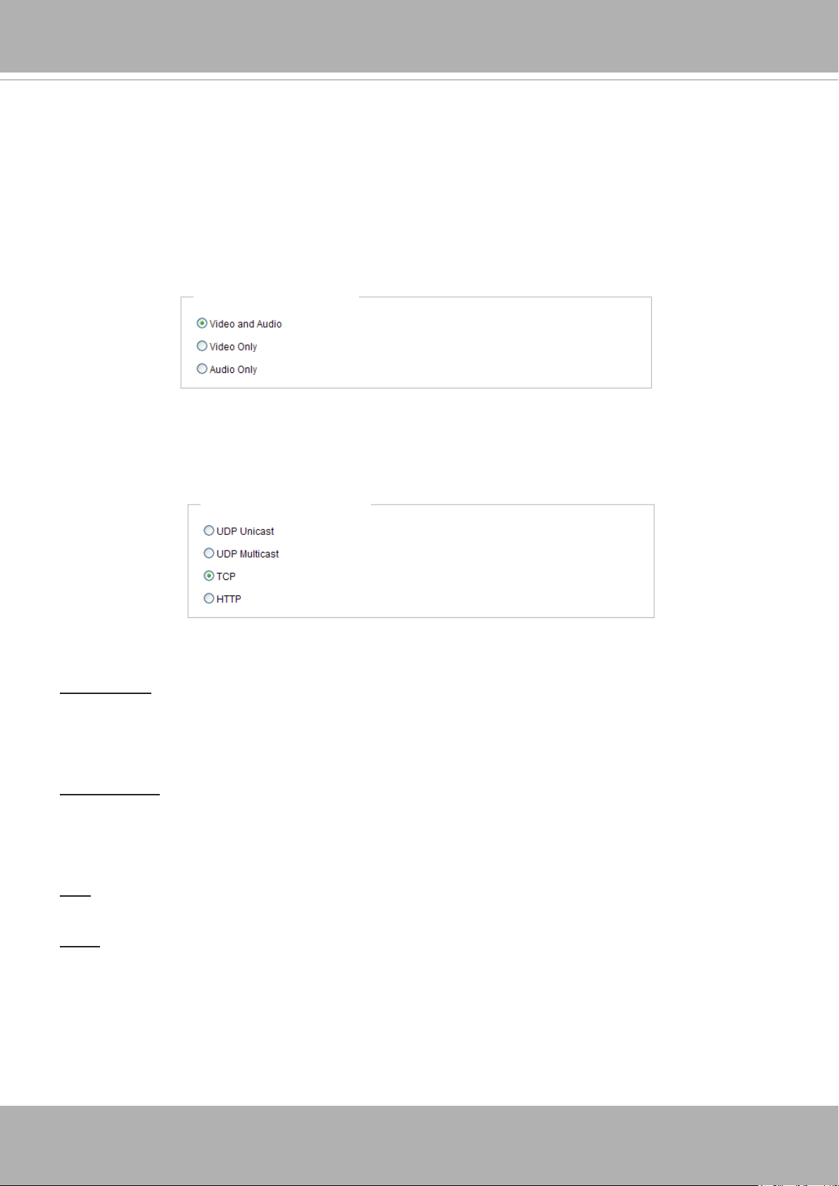
H.264 / MPEG-4 Media Options
H.264/MPEG-4 Media Options
Select to stream video or audio data or both� This is enabled only when the video mode is set to H�264 or
MPEG-4�
H.264 / MPEG-4 Protocol Options
H.264/MPEG-4 Protocol Options
Depending on your network environment, there are four transmission modes of H�264 or MPEG-4
streaming:
UDP unicast: This protocol allows for more real-time audio and video streams. However, network
packets may be lost due to network burst trafc and images may be broken. Activate UDP connection
when occasions require time-sensitive responses and the video quality is less important� Note that each
unicast client connecting to the server takes up additional bandwidth and the Network Camera allows up
to ten simultaneous accesses�
UDP multicast: This protocol allows multicast-enabled routers to forward network packets to all clients
requesting streaming media� This helps to reduce the network transmission load of the Network Camera
while serving multiple clients at the same time. Note that to utilize this feature, the Network Camera must
be configured to enable multicast streaming at the same time� For more information, please refer to
RTSP Streaming on page 63�
TCP: This protocol guarantees the complete delivery of streaming data and thus provides better video
quality� The downside of this protocol is that its real-time effect is not as good as that of the UDP protocol�
HTTP: This protocol allows the same quality as TCP protocol without needing to open specic ports for
streaming under some network environments. Users inside a firewall can utilize this protocol to allow
streaming data through�
26 — User’s Manual
VIVOTEK
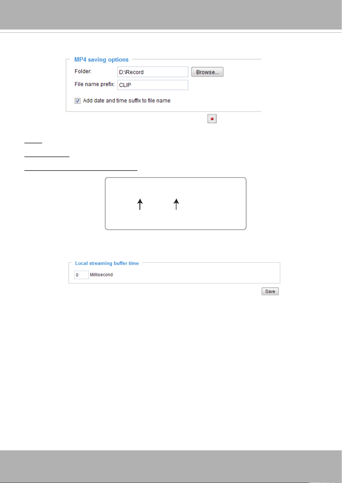
MP4 Saving Options
Users can record live video as they are watching it by clicking Start MP4 Recording on the main
page. Here you can specify the storage destination and le name.
Folder: Specify a storage destination for the recorded video les.
File name prex: Enter the text that will be appended to the front of the video le name.
Add date and time sufx to the le name: Select this option to append the date and time to the end of the
le name.
CLIP_20110628-180853
File name prefix
Date and time suffix
The format is: YYYYMMDD_HHMMSS
Local Streaming Buffer Time
Due to the unsteady bandwidth ow, the live streaming may lag and not be very smoothly. If you enable
this option, the live streaming will be stored on the camera’s buffer area for a few seconds before playing
on the live viewing window� This will help you see the streaming more smoothly� If you enter 3000
Millisecond, the streaming will delay for 3 seconds�
User’s Manual — 27

VIVOTEK
Joystick settings
Enable Joystick
Connect a joystick to a USB port on your management computer� Supported by the plug-in
(Microsoft’s DirectX), once the plug-in for the web console is loaded, it will automatically detect if
there is any joystick on the computer� The joystick should work properly without installing any other
driver or software�
Then you can begin to configure the joystick settings of connected devices� Please follow the
instructions below to enable joystick settings�
1� Select a detected joystick, if there are multiple, from the Selected joystick menu� If your joystick
is not detected, if may be defective�
2� Click Calibrate or Congure buttons to congure the joystick-related settings.
NOTE:
• If you want to assign Preset actions to your joystick, the preset locations should be congured in
advance in the Conguration > PTZ page.
• If your joystick is not working properly, it may need to be calibrated� Click the Calibrate button
to open the Game Controllers window located in Microsoft Windows control panel and follow the
instructions for trouble shooting�
• The joystick will appear in the Game Controllers list in the Windows Control panel� If you want to
check out for your devices, go to the following page: Start -> Control Panel -> Game Controllers.
28 — User’s Manual
VIVOTEK
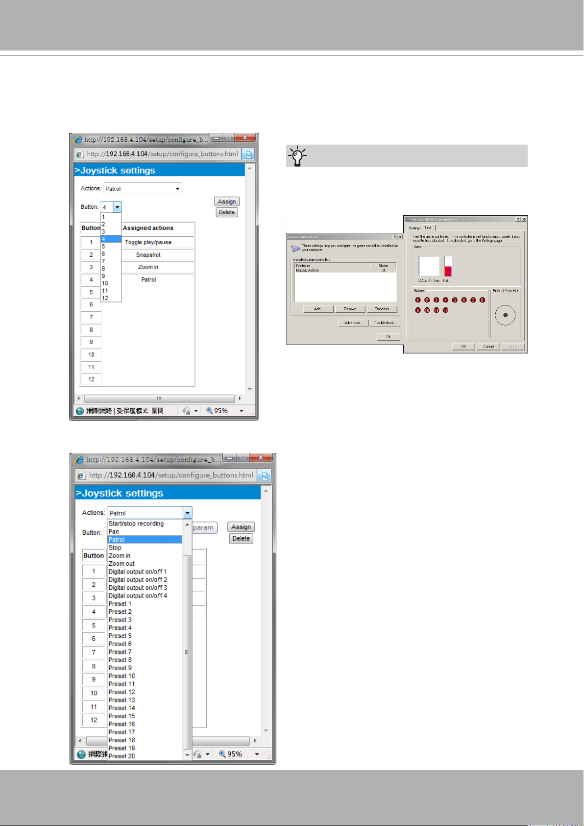
Buttons Conguration
Click the Congure Buttons button, a window will prompt as shown below� Please follow the steps
below to congure your joystick buttons:
1� Select a button number from the Button # pull-down menu�
Tips
If you are not sure of the locations of each
button, use the Properties window in the Game
Controllers utility�
2� Select a corresponding action, such as Patrol or Preset#�
3�
Click the Assign button to assign an
action to the button� You can delete an
association by selecting a button number,
and then click the Delete button�
Repeat the process until you are done
with the configuration of all preferred
actions�
The buttons you dene should appear on
the button list accordingly�
4� Please remember to c
button on the Client settings page to
preserver your settings�
lick the Save
User’s Manual — 29
VIVOTEK
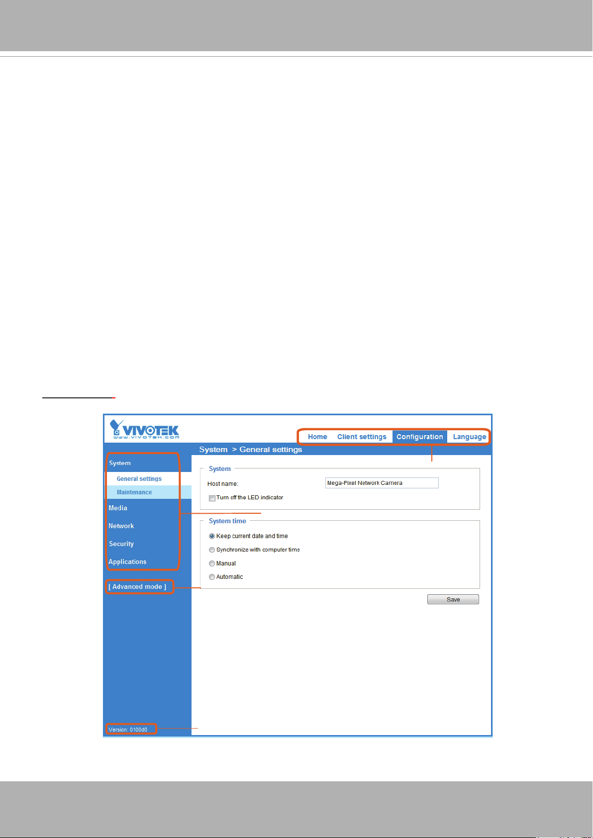
Conguration
Click Configuration on the main page to enter the camera setting pages� Note that only
Administrators can access the conguration page.
VIVOTEK offers an easy-to-use user interface that helps you set up your network camera with
minimal effort. To simplify the setting procedure, two types of user interfaces are available:
Advanced Mode for professional users and Basic Mode for entry-level users� Some advanced
functions (PTZ/ Event/ Recording/ Local storage) are not displayed in Basic Mode�
If you want to set up advanced functions, please click [Advanced Mode] on the bottom of the
conguration list to quickly switch to Advanced Mode.
In order to simplify the user interface, the detailed information will be hidden unless you click to
unfold a functional item. When you click on the rst sub-item, the detailed information for the rst
sub-item will be displayed; when you click on the second sub-item, the detailed information for
the second sub-item will be displayed and that of the rst sub-item will be hidden.
The following is the interface of the Basic Mode and the Advanced Mode:
Basic Mode
Navigation Area
Configuration List
Click to switch to Advanced Mode
30 — User’s Manual
Firmware Version
Loading…
VIVOTEK FD8136 – самая маленькая в мире фиксированная купольная сетевая камера. Питание по Ethernet (PoE), быстрая и легкая установка за 120 секунд.
Камера FD8136 оснащена мегапиксельным сенсором, обеспечивающим съемку с разрешением 1280×800 при скорости 30 кадр/сек в режиме сжатия по уже ставшему стандартным протоколу H.264, который позволяет существенно сократить размер видеофайлов при сохранении пропускной способности сети. Совместимость со стандартами MPEG-4 и MJPEG позволяет передавать видео в любом из этих форматов самым разнообразным приложениям.
Наличие 3х вариантов исполнения с различными фокусными расстояниями позволяет использовать FD8136 в самой различной обстановке – в офисах, лифтах, кампусах, предприятиях розничной торговли, медицинских учреждениях и т.д. Обладая размером всего 90 мм в диаметре, камера VIVOTEK FD8136 является действительно универсальной камерой наблюдения, удовлетворяющей требованиям самых разнообразных задач внутреннего видеонаблюдения. Комплект поставки также включает программу VIVOTEK для 32-канальной записи. Наличие этих и множества других функций делают камеру FD8136 идеальным решением для ваших задач, связанных с видеонаблюдением.
Видео
IP камера Vivotek FD8136 обладает высоким качеством съёмки видео. Это достигается за счёт реализации всех возможностей матрицы CMOS. Максимальное разрешение съёмки составляет 1280×800 точек. При таком значении можно разглядеть на расстоянии не только лица людей, но и относительно небольшие надписи. Наибольшая частота кадров составляет 30 в секунду. Она достигается при любом разрешении, что является важным преимуществом перед продукцией конкурентов или аналогами. Для увеличения заданной области используется шестнадцатикратный цифровой зум.
Компрессия выполняется в одном из доступных форматов: MPEG-4, MJPEG и H.264. Последний вариант предоставляет широкие возможности в плане передачи видео высокого качества при ограниченной полосе частот. Присутствует функция подавления шумов, гарантирующая отсутствие помех. Весьма популярной особенностью является наличие нескольких потоков в процессе съёмки. Для каждого из них клиент может задавать конкретные параметры работы.
Аудио
Эффективная запись аудио с использованием встроенного микрофона подразумевает радиус действия около 5 метров. Для сжатия сигнала применяется формат G.711. Он позволяет добиться минимального показателя шумов при обеспечении высокой эффективности передачи.
Корпус
Данная IP камера обладает корпусом купольного типа, который выполнен из высокопрочного пластика. Изделие не считается защищённым от актов вандализма, но может гарантировать устойчивость к воздействию пыли и ряда других факторов. Объектив находится за специальным пластиковым куполом. Особая технология не позволяет пыли скапливаться на поверхности за счёт электростатических сил.
Сеть
Чтобы получить стабильный и качественный доступ к сети, применяется технология 10/100 Мбит/с Ethernet. Устройство поддерживает одновременную передачу информации до 10 пользователям.
5 причин почему стоит купить Vivotek FD8136-F2(black) в MetraCom
- Компания MetraCom на рынке с 2001 года.
- MetraCom является надежным дилером. (Дипломы)
- Работаем с известными компаниями (Наши партнеры)
- Постоянным клиентам даем хорошие скидки, отсрочки в платежах и другие бонусы (мы всегда сможем договориться :))
- Мы уверенны в качестве каждой камеры Vivotek, т.к. профессионально занимаемся монтажом видеонаблюдения в Москве.
Видеообзор Vivotek FD8136-F2(black)
Хорошее руководство по эксплуатации
Законодательство обязывает продавца передать покупателю, вместе с товаром, руководство по эксплуатации Vivotek FD8136-F2. Отсутствие инструкции либо неправильная информация, переданная потребителю, составляют основание для рекламации в связи с несоответствием устройства с договором. В законодательстве допускается предоставлении руководства в другой, чем бумажная форме, что, в последнее время, часто используется, предоставляя графическую или электронную форму инструкции Vivotek FD8136-F2 или обучающее видео для пользователей. Условием остается четкая и понятная форма.
Что такое руководство?
Слово происходит от латинского «instructio», тоесть привести в порядок. Следовательно в инструкции Vivotek FD8136-F2 можно найти описание этапов поведения. Цель инструкции заключается в облегчении запуска, использования оборудования либо выполнения определенной деятельности. Инструкция является набором информации о предмете/услуге, подсказкой.
К сожалению немного пользователей находит время для чтения инструкций Vivotek FD8136-F2, и хорошая инструкция позволяет не только узнать ряд дополнительных функций приобретенного устройства, но и позволяет избежать возникновения большинства поломок.
Из чего должно состоять идеальное руководство по эксплуатации?
Прежде всего в инструкции Vivotek FD8136-F2 должна находится:
— информация относительно технических данных устройства Vivotek FD8136-F2
— название производителя и год производства оборудования Vivotek FD8136-F2
— правила обслуживания, настройки и ухода за оборудованием Vivotek FD8136-F2
— знаки безопасности и сертификаты, подтверждающие соответствие стандартам
Почему мы не читаем инструкций?
Как правило из-за нехватки времени и уверенности в отдельных функциональностях приобретенных устройств. К сожалению само подсоединение и запуск Vivotek FD8136-F2 это слишком мало. Инструкция заключает ряд отдельных указаний, касающихся функциональности, принципов безопасности, способов ухода (даже то, какие средства стоит использовать), возможных поломок Vivotek FD8136-F2 и способов решения проблем, возникающих во время использования. И наконец то, в инструкции можно найти адресные данные сайта Vivotek, в случае отсутствия эффективности предлагаемых решений. Сейчас очень большой популярностью пользуются инструкции в форме интересных анимаций или видео материалов, которое лучше, чем брошюра воспринимаются пользователем. Такой вид инструкции позволяет пользователю просмотреть весь фильм, не пропуская спецификацию и сложные технические описания Vivotek FD8136-F2, как это часто бывает в случае бумажной версии.
Почему стоит читать инструкции?
Прежде всего здесь мы найдем ответы касательно конструкции, возможностей устройства Vivotek FD8136-F2, использования отдельных аксессуаров и ряд информации, позволяющей вполне использовать все функции и упрощения.
После удачной покупки оборудования/устройства стоит посвятить несколько минут для ознакомления с каждой частью инструкции Vivotek FD8136-F2. Сейчас их старательно готовят или переводят, чтобы они были не только понятными для пользователя, но и чтобы выполняли свою основную информационно-поддерживающую функцию.
English
- Bedienungsanleitung Vivotek FD8136-F2
- Vivotek FD8136-F2 User Manual
- Manual Usuario Vivotek FD8136-F2
- Mode d’emploi Vivotek FD8136-F2
- Istruzioni Vivotek FD8136-F2
- инструкция Vivotek FD8136-F2
- Vivotek FD8136-F2の取扱説明書
- Handleiding Vivotek FD8136-F2
- Manual de uso Vivotek FD8136-F2
Need user manual? We will help you to find it and save your time.
- 1 pages
- 0.05 mb
The Vivotek FD8136-F2 and other products you use every day were certainly offered in the manual set. We know from our users’ experience that most of people do not really attach importance to these manuals. Many instructions, immediately after the purchase, go into the trash along with the box, which is a mistake. Get acquainted with the information concerning the manual for Vivotek FD8136-F2, which will help you to avoid troubles in the future.
Important note — be sure to read the Vivotek FD8136-F2 at least once
If you do not want to read brochures every time concerning a Vivotek FD8136-F2 or other products, it is enough to read them once only — just after buying the device. You will then acquire basic knowledge to maintain Vivotek FD8136-F2 in good operating condition to make it easily reach the intended life cycle. Then you can put away the manual on a shelf and use it again only in a situation where you’re not sure whether you perform maintenance of the product appropriately. Proper maintenance is a necessary part of your satisfaction from Vivotek FD8136-F2.
Once a year, clean the closet where you keep all your devices manuals and throw out the ones that you don’t use. This will help you maintain order in your home base of manuals.
Summary of Contents for Vivotek FD8136-F2
What does the Vivotek FD8136-F2 manual include? Why is it worth reading?
- Warranty and details concerning the maintenance of the product
It is a good idea to attach a document of purchase of the device to this page of the manual. If something bad happens while using a Vivotek FD8136-F2, you will have a set of documents that are required to obtain warranty repairs. It is in this part of the manual that you will also find information about the authorized service points of Vivotek FD8136-F2 as well as how you can properly maintain the device by yourself so as not to lose the warranty for the product. - Assembly guidelines and Setup
Do not lose your nerves and time for trying to assembly the product and launch it on your own. Use the instructions of the Vivotek FD8136-F2 manufacturer to run the product properly, without unnecessary risk of damage to the equipment. - Information concerning additional parts (included in the set and optional)
By looking through this part of the document, you will be able to verify whether your Vivotek FD8136-F2 has been delivered to you with a full set of accessories. You will also be able to find out what optional parts or accessories to Vivotek FD8136-F2 you will be able to find and buy to your device. - Troubleshooting
The most common problems that concern Vivotek FD8136-F2 and how to solve them. This is a very useful part of the manual which will save you a lot of time related to finding a solution. 90% of the problems with a Vivotek FD8136-F2 are common to many users. - Power requirements and energy class
Information concerning the amount of energy used as well as recommendations regarding the installation and supply for Vivotek FD8136-F2. Read to optimally use the Vivotek FD8136-F2 and not to consume more power than is necessary for the proper operation of the product. - Special functions of the Vivotek FD8136-F2
Here you can learn how to customize the product Vivotek FD8136-F2. You will learn what additional features can help you use the product Vivotek FD8136-F2 in a comfortable way and what functions of your device are the best to perform specific tasks.
As you can see, in the manual you will find information that will really help you use your product. It is good to get acquainted with it to avoid disappointments resulting from a shorter exploitation time of the product Vivotek FD8136-F2 than expected. However, if you cannot be convinced to collect manuals at your home, our website will provide you with help. You should find here the manuals for most of your devices, including Vivotek FD8136-F2.
Comments (0)
Ultra-mini Fixed Dome
Network Camera
FD8136
1MP • Stylish Design •
Easy Installation
VIVOTEK FD8136 is the world’s smallest network fixed dome
camera. With installation as easy as one-two-three and Power
over Ethernet (PoE) functionality, setup time is completed in less
than 120 seconds, making installation quick and easy.
The FD8136 features a megapixel sensor enabling viewing
resolution of 1280×800 at 30 fps, and also supports the
industry-standard H.264 compression technology, drastically
reducing file sizes and conserving valuable network bandwidth.
With MPEG-4 and MJPEG compatibility also included, video
streams can also be transmitted in any of these formats for
versatile applications.
Designed with selectable focal lengths, FD8136 can be used in
various environments, including but not limited to offices,
elevators, campus, chain stores, boutique stores and health
care facilities. At the size of only 90 mm in diameter, VIVOTEK
FD8136 is truly an all-in-one surveillance solution that meets a
wide variety of needs for indoor surveillance. The package also
includes VIVOTEK’s 32-channel recording software. With all this
and more, the FD8136 is the ideal solution for your surveillance
needs.
● 1-Megapixel CMOS Sensor
● 30 fps @ 1280×800
● Real-time H.264, MPEG-4 and MJPEG Compression
(Triple Codec)
● Built-in IEEE 802.3af Compliant PoE
● Built-in MicroSD/SDHC Card Slot for On-board Storage
● Compact and Stylish Design
● Easy Installation
Features
Ultra-mini Size
Retail
Office
Elevator