


Version 1.1
Published October 2020
Copyright©2020 ASRock INC. All rights reserved.
Copyright Notice:
No part of this documentation may be reproduced, transcribed, transmitted, or
translated in any language, in any form or by any means, except duplication of
documentation by the purchaser for backup purpose, without written consent of
ASRock Inc.
Products and corporate names appearing in this documentation may or may not
be registered trademarks or copyrights of their respective companies, and are used
only for identication or explanation and to the owners’ benet, without intent to
infringe.
Disclaimer:
Specications and information contained in this documentation are furnished for
informational use only and subject to change without notice, and should not be
constructed as a commitment by ASRock. ASRock assumes no responsibility for
any errors or omissions that may appear in this documentation.
With respect to the contents of this documentation, ASRock does not provide
warranty of any kind, either expressed or implied, including but not limited to
the implied warranties or conditions of merchantability or tness for a particular
purpose.
In no event shall ASRock, its directors, ocers, employees, or agents be liable for
any indirect, special, incidental, or consequential damages (including damages for
loss of prots, loss of business, loss of data, interruption of business and the like),
even if ASRock has been advised of the possibility of such damages arising from any
defect or error in the documentation or product.
is device complies with Part 15 of the FCC Rules. Operation is subject to the following
two conditions:
(1) this device may not cause harmful interference, and
(2) this device must accept any interference received, including interference that
may cause undesired operation.
CALIFORNIA, USA ONLY
e Lithium battery adopted on this motherboard contains Perchlorate, a toxic substance
controlled in Perchlorate Best Management Practices (BMP) regulations passed by the
California Legislature. When you discard the Lithium battery in California, USA, please
follow the related regulations in advance.
“Perchlorate Material-special handling may apply, see ww w.dtsc.ca.gov/hazardouswaste/
perchlorate”
ASRock Website: http://www.asrock.com

AUSTRALIA ONLY
Our goods come with guarantees that cannot be excluded under the Australian Consumer
Law. You are entitled to a replacement or refund for a major failure and compensation for
any other reasonably foreseeable loss or damage caused by our goods. You are also entitled
to have the goods repaired or replaced if the goods fail to be of acceptable quality and the
failure does not amount to a major failure. If you require assistance please call ASRock Tel
: +886-2-28965588 ext.123 (Standard International call charges apply)
e terms HDMI® and HDMI High-Denition Multimedia Interface, and the HDMI
logo are trademarks or registered trademarks of HDMI Licensing LLC in the United
States and other countries.

Contents
Chapter 1 Introduction 1
1.1 Package Contents 1
1.2 Specications 2
1.3 Motherboard Layout 7
1.4 I/O Panel 9
Chapter 2 Installation 10
2.1 Installing the CPU 11
2.2 Installing the CPU Fan and Heatsink 13
2.3 Installing Memory Modules (DIMM) 22
2.4 Expansion Slots (PCI Express Slots) 26
2.5 Jumpers Setup 27
2.6 Onboard Headers and Connectors 28
2.7 M.2_SSD (NGFF) Module Installation Guide (M2_1) 33
2.8 M.2_SSD (NGFF) Module Installation Guide (M2_2) 36
Chapter 3 Software and Utilities Operation 39
3.1 Installing Drivers 39
3.2 ASRock Live Update & APP Shop 40
3.2.1 UI Overview 40
3.2.2 Apps 41
3.2.3 BIOS & Drivers 44
3.2.4 Setting 45
3.3 ASRock RGB LED 46

Chapter 4 UEFI SETUP UTILITY 47
4.1 Introduction 48
4.1.1 UEFI Menu Bar 48
4.1.2 Navigation Keys 49
4.2 Main Screen 50
4.3 OC Tweaker Screen 51
4.4 Advanced Screen 53
4.4.1 CPU Conguration 54
4.4.2 North Bridge Conguration 55
4.4.3 South Bridge Conguration 56
4.4.4 Storage Conguration 57
4.4.5 Super IO Conguration 58
4.4.6 ACPI Conguration 59
4.4.7 Trusted Computing 60
4.5 Tools 61
4.6 Hardware Health Event Monitoring Screen 63
4.7 Security Screen 65
4.8 Boot Screen 66
4.9 Exit Screen 68

Chapter 1 Introduction
ank you for purchasing ASRock X370 Pro4 motherboard, a reliable motherboard
produced under ASRock’s consistently stringent quality control. It delivers excellent
performance with robust design conforming to ASRock ’s commitment to quality
and endurance.
In this manual, Chapter 1 and 2 contains the introduction of the motherboard
and step-by-step installation guides. Chapter 3 contains the operation guide of the
soware and utilities. Chapter 4 contains the conguration guide of the BIOS setup.
Becau se the motherboard specications and the BIOS soware might be updated, the
content of this manual will be subject to change without notice. In ca se any modications of this manual occur, the updated version will be available on ASRock’s website
without further notice. If you require technical suppor t related to this motherboard,
please visit our website for spe cic information about the model you are using. You
may nd the l atest VGA cards and CPU support list on ASRock ’s website a s well.
ASRock website http://www.a srock .com.
1.1 Package Contents
ASRock X370 Pro4 Motherboard (ATX Form Factor)
•
ASRock X370 Pro4 Quick Installation Guide
•
ASRock X370 Pro4 Support CD
•
1 x I/O Panel Shield
•
2 x Serial ATA (SATA) Data Cables (Optional)
•
2 x Screws for M.2 Sockets (Optional)
•
X370 Pro4
English
1

English
1.2 Specications
Platform
CPU
Chipset
Memory
•
•
•
•
•
•
•
•
•
•
•
•
•
•
* For Ryzen Series CPUs (Picasso and Raven Ridge), ECC is only
supported with PRO CPUs.
* Please refer to Memory Support List on ASRock’s website for
more information. (http://www.asrock.com/)
* Please refer to page 22 for the table for AMD non-XMP mem-
ory frequency support. For more details, please refer to the QVL
on ASRock’s website.
•
•
ATX Form Factor
Solid Capacitor design
Supports AMD Socket AM4 A-Series APUs (Bristol Ridge)
and Ryzen Series CPUs (Matisse, Picasso, Summit Ridge,
Raven Ridge and Pinnacle Ridge)
Digi Power design
9 Power Phase design
AMD Promontory X370
Dual Channel DDR4 Memory Technology
4 x DDR4 DIMM Slots
AMD Ryzen series CPUs (Matisse) support DDR4
3200/2933/2667/2400/2133 ECC & non-ECC, un-buered
memory*
AMD Ryzen series CPUs (Pinnacle Ridge) support DDR4
3200+(OC)/2933(OC)/2667/2400/2133 ECC & non-ECC, un-
buered memory*
AMD Ryzen series CPUs (Picasso) support DDR4
2933/2667/2400/2133 non-ECC, un-buered memory*
AMD Ryzen series CPUs (Summit Ridge) support DDR4
3200+(OC)/2933(OC)/2667/2400/2133 ECC & non-ECC, un-
buered memory*
AMD Ryzen series CPUs (Raven Ridge) support DDR4
3200+(OC)/2933/2667/2400/2133 non-ECC, un-buered
memory*
AMD 7th Gen A-Series APUs support DDR4 2400/2133 non-
ECC, un-buered memory*
Max. capacity of system memory: 64GB
15μ Gold Contact in DIMM Slots
2

X370 Pro4
Expansion
Slot
Graphics
AMD Ryzen series CPUs (Matisse, Summit Ridge and Pinnacle
Ridge)
2 x PCI Express 3.0 x16 Slots (single at x16 (PCIE2); dual at
•
x16 (PCIE2) / x4 (PCIE4))*
AMD 7th A-Series APUs
2 x PCI Express 3.0 x16 Slots (single at x8 (PCIE2); dual at x8
•
(PCIE2) / x2 (PCIE4))*
AMD Ryzen series CPUs (Picasso, Raven Ridge)
2 x PCI Express 3.0 x16 Slots (single at x8 (PCIE2); dual at x8
•
(PCIE2) / x4 (PCIE4))*
AMD Athlon series CPUs
2 x PCI Express 3.0 x16 Slots (single at x4 (PCIE2); dual at x4
•
(PCIE2) / x2 (PCIE4))*
* Supports NVMe SSD as boot disks
* If M2_1 is occupied, PCIE4 will be disabled.
4 x PCI Express 2.0 x1 Slots
•
Supports AMD Quad CrossFireXTM and CrossFireXTM**
•
** is feature is only supported with Ryzen Series CPUs
(Matisse, Summit Ridge, Pinnacle Ridge, Picasso and Raven
Ridge).
Integrated AMD RadeonTM Vega Series Graphics in Ryzen
•
Series APU*
Integrated AMD RadeonTM R-Series Graphics in A-series
•
APU*
* Actual support may vary by CPU
DirectX 12, Pixel Shader 5.0
•
Shared memory default 2GB. Max Shared memory supports
•
up to 16GB.
* e Max shared memory 16GB requires 32GB system memory
installed.
ree graphics output options: D-Sub, DVI-D and HDMI
•
Supports Triple Monitor
•
Supports HDMI 1.4 with max. resolution up to 4K x 2K
•
(4096×2160) @ 24Hz / (3840×2160) @ 30Hz
Supports DVI-D with ma x. resolution up to 1920×1200 @
•
60Hz
Supports D-Sub with max. resolution up to 1920×1200 @
•
60Hz
English
3

Audio
LAN
Rear Panel
I/O
Supports Auto Lip Sync, Deep Color (12bpc), xvYCC and
•
HBR (High Bit Rate Audio) with HDMI 1.4 Port (Compliant
HDMI monitor is required)
Supports HDCP 1.4 with DVI-D and HDMI 1.4 Ports
•
Supports Full HD 1080p Blu-ray (BD) playback with DVI-D
•
and HDMI 1.4 Ports
7.1 CH HD Audio with Content Protection (Realtek ALC892
•
Audio Codec)
Premium Blu-ray Audio support
•
Supports Surge Protection
•
ELNA Audio Caps
•
PCIE x1 Gigabit LAN 10/100/1000 Mb/s
•
Realtek RTL8111GR
•
Supports Wake-On-LAN
•
Supports Lightning/ESD Protection
•
Supports LAN Cable Detection
•
Supports Energy Ecient Ethernet 802.3az
•
Supports PXE
•
1 x PS/2 Mouse/Keyboard Port
•
1 x D-Sub Port
•
1 x DVI-D Port
•
1 x HDMI Port
•
2 x USB 2.0 Ports (Supports ESD Protection)
•
1 x USB 3.2 Gen1 Type-C Port (Supports ESD Protection)
•
5 x USB 3.2 Gen1 Ports (Supports ESD Protection (Supports
•
ESD Protection)
1 x RJ-45 LAN Port with LED (ACT/LINK LED and SPEED
•
LED)
HD Audio Jacks: Line in / Front Speaker / Microphone
•
English
4
Storage
4 x SATA3 6.0 Gb/s Connectors, support RAID (RAID 0,
•
RAID 1 and RAID 10), NCQ, AHCI and Hot Plug*
2 x SATA3 6.0 Gb/s Connectors by ASMedia ASM1061, sup-
•
port NCQ, AHCI and Hot Plug
* M2_ 2 and SATA3_3 share lanes. If either one of them is in use,
the other one will be disabled.

Connector
1 x Ultra M.2 Socket (M2_1), supports M Key type
•
2242/2260/2280 M.2 PCI Express module up to Gen3 x4 (32
Gb/s) (with Matisse, Picasso, Summit Ridge, Raven Ridge and
Pinnacle Ridge) or Gen3 x2 (16 Gb/s) (with A-Series APU and
Athlon series APU)**
** If M2_1 is occupied, PCIE4 will be disabled.
** Supports NVMe SSD as boot disks
** Supports ASRock U.2 Kit
1 x M.2 Socket (M2_2), supports M Key type
•
2230/2242/2260/2280/22110 M.2 SATA3 6.0 Gb/s module
1 x COM Port Header
•
1 x TPM Header
•
1 x Power LED and Speaker Header
•
1 x RGB LED Header
•
* Supports up to 12V/3A, 36W LED Strip
1 x AMD Fan LED Header
•
1 x CPU Fan Connector (4-pin)
•
* e CPU Fan Connector supports the CPU fan of ma ximum
1A (12W) fan power.
3 x Chassis Fan Connectors (4-pin) (Smart Fan Speed
•
Control)
* CHA_FAN2 and CHA_FAN3 can auto detect if 3-pin or 4-pin
fan is in use.
1 x 24 pin ATX Power Connector
•
1 x 8 pin 12V Power Connector
•
1 x Front Panel Audio Connector
•
2 x USB 2.0 Headers (Support 4 USB 2.0 ports) (Supports ESD
•
Protection)
1 x USB 3.2 Gen1 Header (Supports 2 USB 3.2 Gen1 ports)
•
(Supports ESD Protection)
X370 Pro4
BIOS
Feature
AMI UEFI Legal BIOS with multilingual GUI support
•
Supports “Plug and Play”
•
ACPI 5.1 compliance wake up events
•
Supports jumperfree
•
SMBIOS 2.3 support
•
DRAM Voltage multi-adjustment
•
English
5

CPU/Chassis temperature sensing
Hardware
Monitor
OS
Certications
* For detailed product information, please visit our website: http://ww w.asrock.com
Please realize that the re is a certain r isk involved with overclo cking, including adju sting the setting in the BIOS, applying Untied Ove rclocking Technology, or using thirdparty o verclocking tools. Overclocking may aect your system’s stability, or even c ause
damage to the components and dev ices of your system. It should be done at your own
risk and expense. We are not responsible for possible damage cau sed by overclocking.
•
CPU/Chassis Fan Tachometer
•
CPU/Chassis Quiet Fan
•
CPU/Chassis Fan multi-speed control
•
Voltage monitoring: +12V, +5V, +3.3V, Vcore
•
Microso® Windows® 10 64-bit
•
FCC, CE
•
ErP/EuP ready (ErP/EuP ready power supply is required)
•
English
6
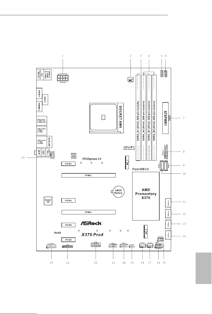
1.3 Motherboard Layout
X370 Pro4
English
7
No. Description
1 ATX 12V Power Connector (ATX12V1)
2 CPU Fan Connector (CPU_FAN1)
3 2 x 288-pin DDR4 DIMM Slots (DDR4_A1, DDR4_B1)
4 2 x 288-pin DDR4 DIMM Slots (DDR4_A2, DDR4_B2)
5 AMD Fan LED Header (AMD_FAN_LED1)
6 RGB LED Header (RGB_HEADER1)
7 ATX Power Connector (ATXPWR1)
8 USB 3.2 Gen1 Header (USB3_ 5_6)
9 SATA3 Connector (SATA3_2)
10 SATA3 Connector (SATA3_1)
11 SATA3 Connector (SATA3_A1)
12 SATA3 Connector (SATA3_A2)
13 SATA3 Connector (SATA3_3)
14 SATA3 Connector (SATA3_4)
15 Power LED and Speaker Header (SPK_PLED1)
16 System Panel Header (PANEL1)
17 Chassis Fan Connector (CHA_FAN2)
18 Chassis Fan Connector (CHA_FAN1)
19 Clear CMOS Jumper (CLRCMOS1)
20 USB 2.0 Header (USB_3_4)
21 USB 2.0 Header (USB_1_2)
22 COM Port Header (COM1)
23 TPM Header (TPMS1)
24 Front Panel Audio Header (HD_ AUDIO1)
25 Chassis Fan Connector (CHA_FAN3)
English
8

1.4 I/O Panel
1
X370 Pro4
4
2
3
5
12
8 791113
6
10
No. Description No. Description
1 USB 2.0 Ports (USB12) 8 USB 3.2 Gen1 Ports (USB3_12)
2 DVI-D Port 9 USB 3.2 Gen1 Port (USB31_TA_1)
3 LAN RJ-45 Port* 10 USB 3.2 Gen1 Type-C Port (USB31_TC_1)
4 Line In (Light Blue)** 11 HDMI Port
5 Front Speaker (Lime)** 12 D-Sub Port
6 Microphone (Pink)** 13 PS/2 Mouse/Keyboard Port
7 USB 3.2 Gen1 Ports (USB3_34)
* ere are two LEDs on each LAN port. Please refer to the table below for the LAN port LED indications .
ACT/LINK L ED
SPEED LE D
LAN Por t
Activity / Link LED Speed LED
Status Description Status Description
O No Link O 10Mbps connection
Blinking Data Activity Orange 100Mbps connection
On Link Green 1Gbps connection
** Function of the Au dio Ports in 7.1-channel Con guration:
Port Function
Light Blue (Rear panel) Rear Speaker Out
Lime (Rear panel) Front Speaker Out
Pink (Rear panel) Central /Subwoofer Speaker Out
Lime (Front panel) Side Speaker Out
English
9

Chapter 2 Installation
is is an ATX form factor motherboard. Before you install the motherboard, study
the conguration of your chassis to ensure that the motherboard ts into it.
Pre-installation Precautions
Take note of the following precautions before you install motherboard components
or change any motherboard settings.
Make sure to unplug the power cord before installing or removing the motherboard.
•
Failure to do so may cause physical injuries to you and damages to motherboard
components.
In order to avoid damage from static electricity to the motherboard’s components,
•
NEVER place your motherboard directly on a carpet. Also remember to use a grounded
wrist strap or touch a safety grounded object before you handle the components.
Hold components by the edges and do not touch the ICs.
•
Whenever you uninstall any components, place them on a grounded anti-static pad or
•
in the bag that comes with the components.
When placing screws to secure the motherboard to the chassis, please do not over-
•
tighten the screws! Doing so may damage the motherboard.
English
10
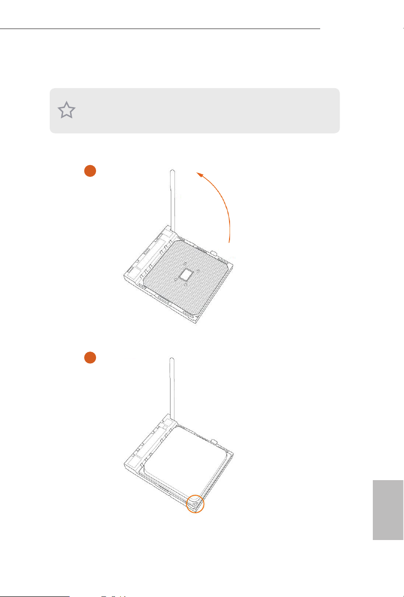
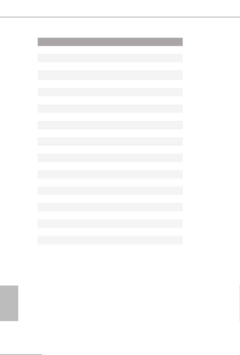
2.1 Installing the CPU
Unplug all power cables be fore installing the CPU.
1
X370 Pro4
2
English
11
3
English
12
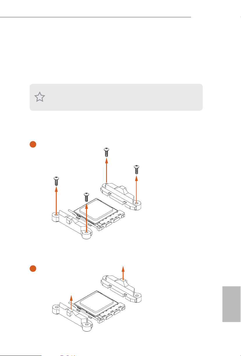
2.2 Installing the CPU Fan and Heatsink
Aer you install the CPU into this motherboard, it is necessary to install a larger
heatsink and cooling fan to dissipate heat. You also need to spray thermal grease
between the CPU and the heatsink to improve heat dissipation. Ma ke sure that the
CPU and the heatsink are securely fastened and in good contact with each other.
Please turn o the power or remove the power cord before changing a CPU or heatsink.
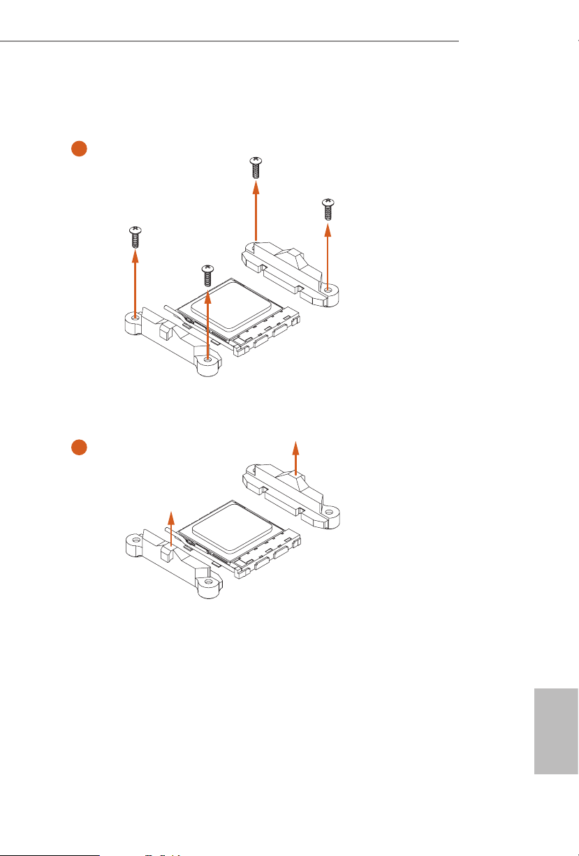
Installing the CPU Box Cooler SR1
1
X370 Pro4
2
English
13

3
English
14
4
1
N
FA
_
U
P
C
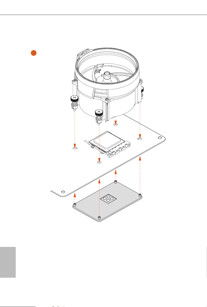
Installing the AM4 Box Cooler SR2
1
X370 Pro4
2
English
15
3
English
16
X370 Pro4
4
1
N
FA
_
U
P
C
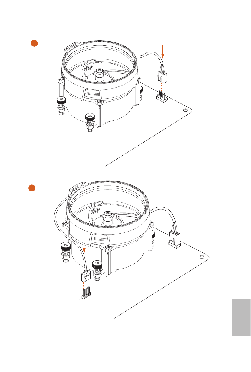
5
4-pin FAN cable
RGB LED Cable
1
N
FA
CPU_
1
D
E
L
_
N
FA
_
D
AM
+12V
*e diagram shown here are for reference only. Please refer to page 32 for the orientation of
AMD Fan LED Header (AMD_FAN_LED1).
English
17

Installing the AM4 Box Cooler SR3
1
English
18
2
Loading…
Version 1.0
Published January 2018
Copyright©2018 ASRock INC. All rights reserved.
Copyright Notice:
No part of this documentation may be reproduced, transcribed, transmitted, or
translated in any language, in any form or by any means, except duplication of
documentation by the purchaser for backup purpose, without written consent of
ASRock Inc.
Products and corporate names appearing in this documentation may or may not
be registered trademarks or copyrights of their respective companies, and are used
only for identication or explanation and to the owners’ benet, without intent to
infringe.
Disclaimer:
Specications and information contained in this documentation are furnished for
informational use only and subject to change without notice, and should not be
constructed as a commitment by ASRock. ASRock assumes no responsibility for
any errors or omissions that may appear in this documentation.
With respect to the contents of this documentation, ASRock does not provide
warranty of any kind, either expressed or implied, including but not limited to
the implied warranties or conditions of merchantability or tness for a particular
purpose.
In no event shall ASRock, its directors, ocers, employees, or agents be liable for
any indirect, special, incidental, or consequential damages (including damages for
loss of prots, loss of business, loss of data, interruption of business and the like),
even if ASRock has been advised of the possibility of such damages arising from any
defect or error in the documentation or product.
is device complies with Part 15 of the FCC Rules. Operation is subject to the following
two conditions:
(1) this device may not cause harmful interference, and
(2) this device must accept any interference received, including interference that
may cause undesired operation.
CALIFORNIA, USA ONLY
e Lithium battery adopted on this motherboard contains Perchlorate, a toxic substance
controlled in Perchlorate Best Management Practices (BMP) regulations passed by the
California Legislature. When you discard the Lithium battery in California, USA, please
follow the related regulations in advance.
“Perchlorate Material-special handling may apply, see www.dtsc.ca.gov/hazardouswaste/
perchlorate”
ASRock Website: http://www.asrock.com
Questo manuale d’istruzione è fornito da trovaprezzi.it. Scopri tutte le offerte per AsRock X370 Pro4 o
Manuals.eu
- Manuals.eu
- ASRock
- Computers & Peripherals
- Mainboards
- X370 Pro4
- User Manual
×
1
2
3
4
5
6
7
8
9
10
11
12
13
14
15
16
17
18
19
20
21
22
23
24
25
26
27
28
29
30
31
32
33
34
35
36
37
38
39
40
41
42
43
44
45
46
47
48
49
50
51
52
53
54
55
56
57
58
59
60
61
62
63
64
65
66
67
68
69
70
71
72
73
74
75
76
⟨
⟩
Copyright © Manuals.eu
Agreement
Privacy Policy
Contact us
Все способы:
- Обновление BIOS на ASRock
- Этап 1: Определение установленной версии БИОС
- Этап 2: Загрузка прошивки с сайта производителя
- Этап 3: Обновление прошивки
- Заключение
- Вопросы и ответы: 19
Продукция компании ASRock пользуется популярностью у пользователей, которые ориентируются на соотношение «цена-качество». Материнские платы этой компании хороши в том числе и легкостью обновления BIOS, если в этой процедуре появится нужда. Сегодня мы хотим познакомить вас с алгоритмом установки обновлений микропрограммы для плат этой компании.
Обновление BIOS на ASRock
Первым делом напомним, что обновлять БИОС следует только в случае необходимости – например, предполагается установка CPU, видеокарты или модулей ОЗУ, которые не поддерживаются текущей версией микропрограммы либо с ней наблюдаются проблемы.
Непосредственно процедура обновления состоит из нескольких этапов: определения версии установленного варианта прошивки, загрузки обновлений с сайта производителя и установки.
Этап 1: Определение установленной версии БИОС
Перед тем как заниматься обновлением, следует узнать, какой вариант микропрограммы в текущий момент используется на материнской плате – это нужно для выбора новейшего варианта. Кроме того, по номеру версии можно найти заметки производителя, в которых указаны возможные неполадки. Определить вариант BIOS можно несколькими методами – подробности процедуры описаны в отдельном руководстве.
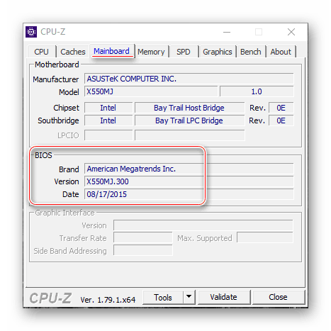
Урок: Как узнать версию BIOS
Этап 2: Загрузка прошивки с сайта производителя
После определения изначальной версии BIOS необходимо загрузить на компьютер новый вариант. Делать это следует с сайта ASRock — только в этом случае гарантируется совместимость и работоспособность микропрограммы.
Внимание! Загрузка файлов BIOS из неофициальных источников и попытка их установки может закончиться поломкой материнской платы!
Перейти на сайт ASRock
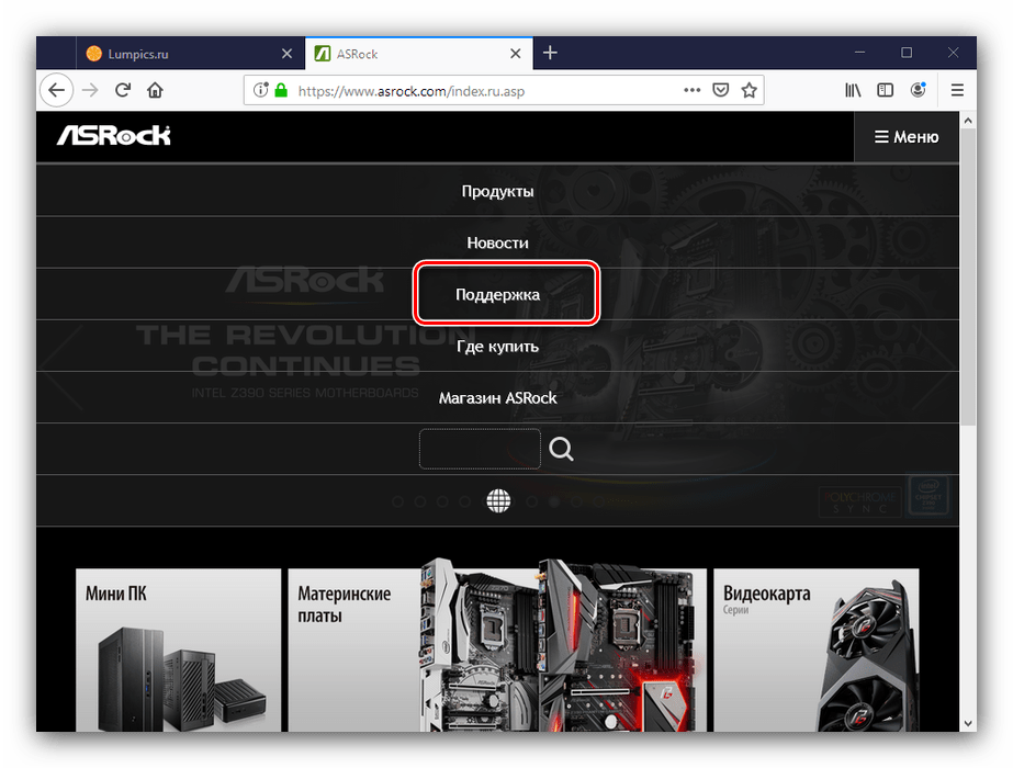
- Воспользуйтесь любым браузером, чтобы перейти к сайту производителя. После открытия страницы задействуйте пункт «Поддержка» в главном меню.
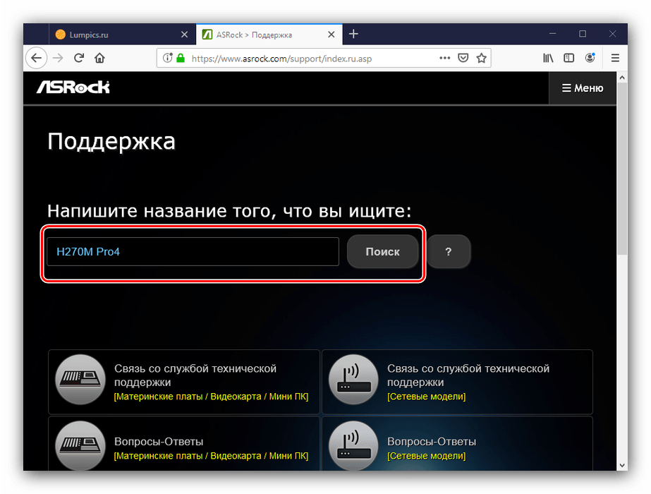
- Введите в поисковой строке название модели вашей «материнки» и нажмите на кнопку поиска. Если вы не знаете точное название модели платы, руководство далее поможет вам в решении этой задачи.

Урок: Как узнать модель материнской платы
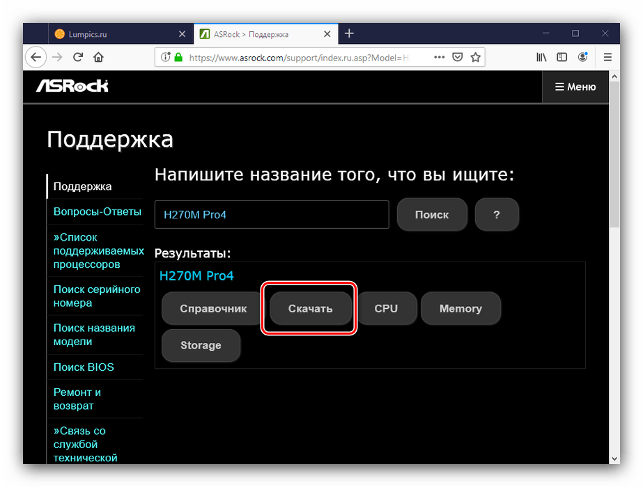
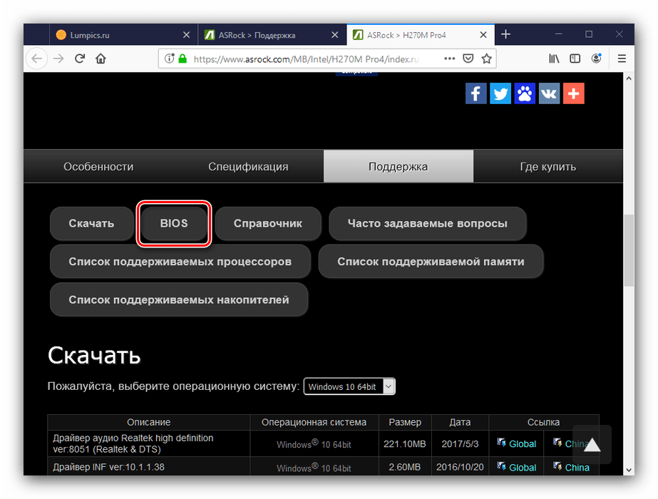
- В результатах поиска используйте кнопку «Скачать».
- Далее кликните по кнопке «BIOS».
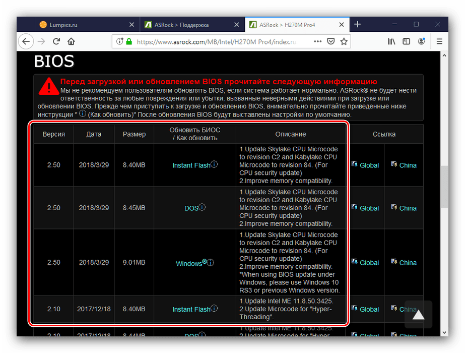
Появится список доступных прошивок. Ориентируйтесь на номер версии и на дату выпуска ПО.
Особое внимание следует обратить на третью колонку таблицы, «Обновить БИОС / Как обновить» – в ней указан метод, которым следует прошивать соответствующий вариант обновления микропрограммы:
Метод обновления Описание Instant Flash Предполагает использование прошивальщика, встроенного в BIOS DOS Прошивать обновления следует из-под специальной DOS-оболочки Windows ® Обновление поставляется в виде файла, который следует запускать в ОС Windows Об особенностях установки каждого из вариантов мы поговорим на третьем этапе.
- Скачать выбранный вариант прошивки можно в столбце «Ссылка», позиция «Global».
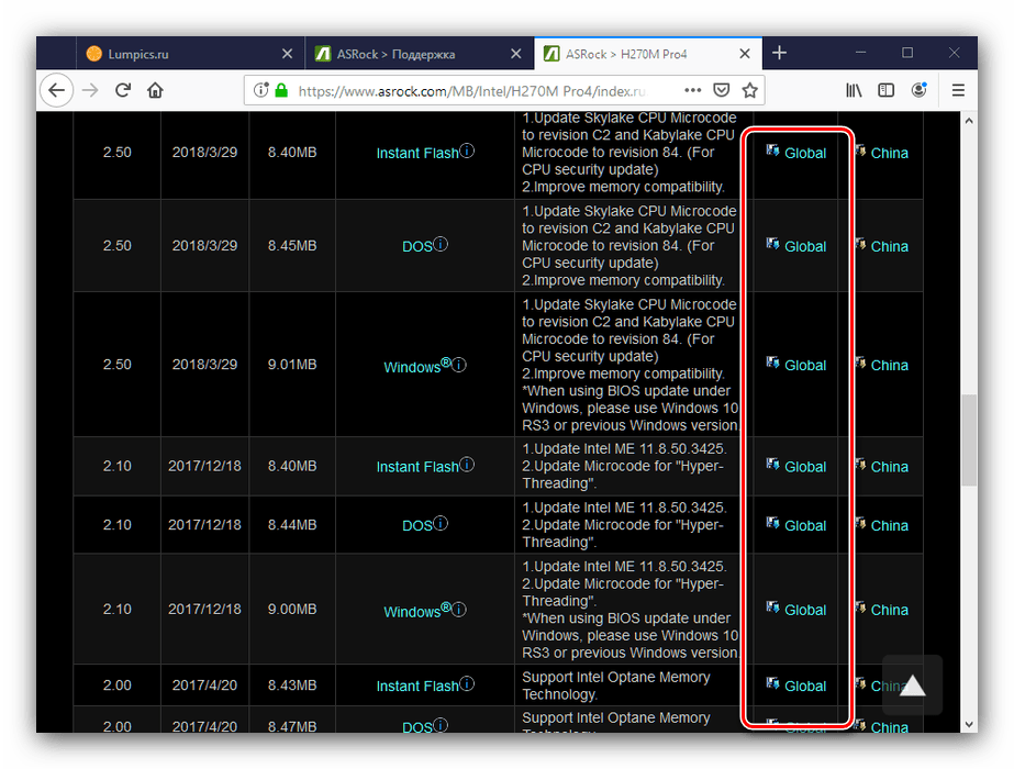
Загрузите прошивку в любое место на жестком диске компьютера и переходите к следующему этапу.
Этап 3: Обновление прошивки
После того как нужные файлы загружены, можно переходить к апдейту встроенного в плату ПО. Процедура может проводиться тремя разными методами, о чём мы упоминали выше. Начнём с самого универсального.
Внимание! Все дальнейшие действия вы совершаете на свой страх и риск!
ASRock Instant Flash
Обновлять БИОС на рассматриваемых платах проще всего через специальную утилиту, встроенную в микропрограмму. Алгоритм следующий:
- Подготовьте флеш-накопитель – объём не более 4 Гб, формат файловой системы FAT32.
Читайте также: Как отформатировать флешку
- Скопируйте файл прошивки в корневую папку используемого накопителя.
- Выключите целевой компьютер, затем подключите подготовленный USB-носитель к одному из портов.
Внимание! Используйте только порты USB 2.0, поскольку с третьей версией протокола процедура может работать нестабильно!
- Включите компьютер, и на этапе первоначальной загрузки нажмите клавиши F2 или Delete для входа в БИОС.
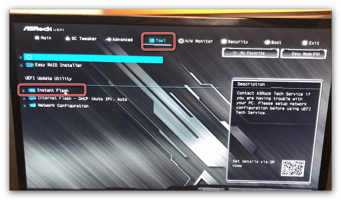
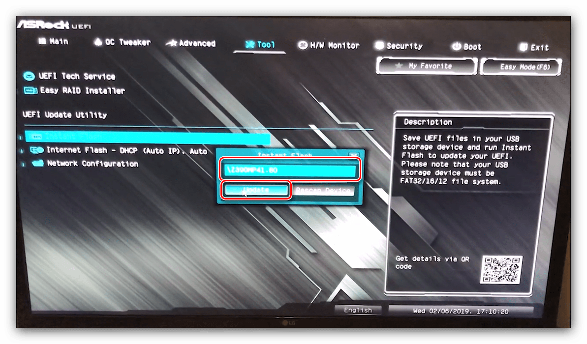
- Перейдите ко вкладке «Smart», на которой выберите «Instant Flash».
- Подождите, пока утилита проверит подключённый накопитель и записанные на нём версии обновлений. Выберите подходящий и кликните по кнопке «Update».
- Дождитесь окончания процедуры обновления, после чего перезагрузите компьютер.
Если всё проделано правильно, у вас будет установлена новейшая версия микропрограммы.
DOS-оболочка
Этот вариант самый сложный из представленных, поэтому использовать его следует только тогда, когда все остальные не подходят.
- Как и в случае с первым методом, сделайте загрузочный накопитель в виде пустой флешки, отформатированной в FAT32.
- Скопируйте в корень накопителя файлы из архива с обновлениями.
- Выключите компьютер и перейдите в BIOS, где настройте загрузку с флешки.
Подробнее: Как настроить БИОС для загрузки с USB
- Выключите компьютер, после чего подсоедините к нему подготовленный накопитель – помните про правило насчёт USB 2.0.
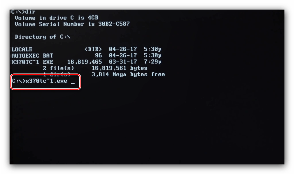
- Включите машину и дождитесь, пока появится интерфейс оболочки. В текстовой строке введите название EXE-файла с прошивкой (формат файла тоже нужно вводить), и нажмите Enter.
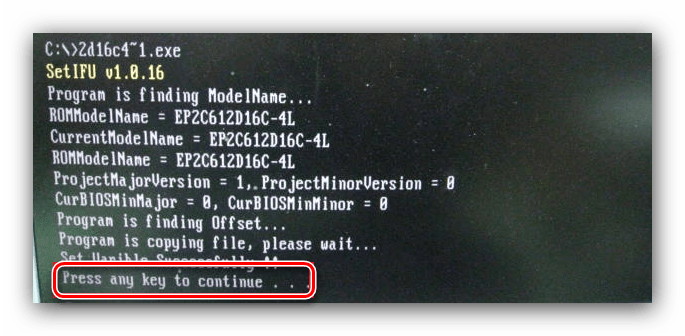
- Подождите, пока система определит совместимость выбранной версии. Если проблем не возникло, интерфейс предложит нажать любую кнопку для перезагрузки.
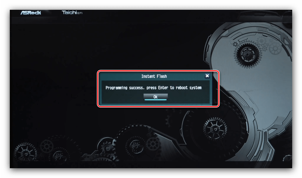
- После перезагрузки начнётся процесс обновления. Дождитесь, пока он завершиться. По окончании получите сообщение с предложением нажать Enter, проделайте это.
- Во время перезагрузки войдите в БИОС. В нём перейдите на вкладку «Exit», в которой задействуйте последовательно опции «Load Defaults» и «Exit Saving Changes».
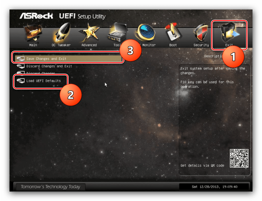
Снова перезагрузите компьютер.
Windows
Вариант с обновлением из-под системы подобен предыдущему, но в некоторых случаях удобнее.
Обратите внимание! Обновление BIOS из-под Виндовс доступно только для версий Windows 10 RS3 и старше – новейшие варианты этой ОС возможность такого метода апдейта не поддерживают!
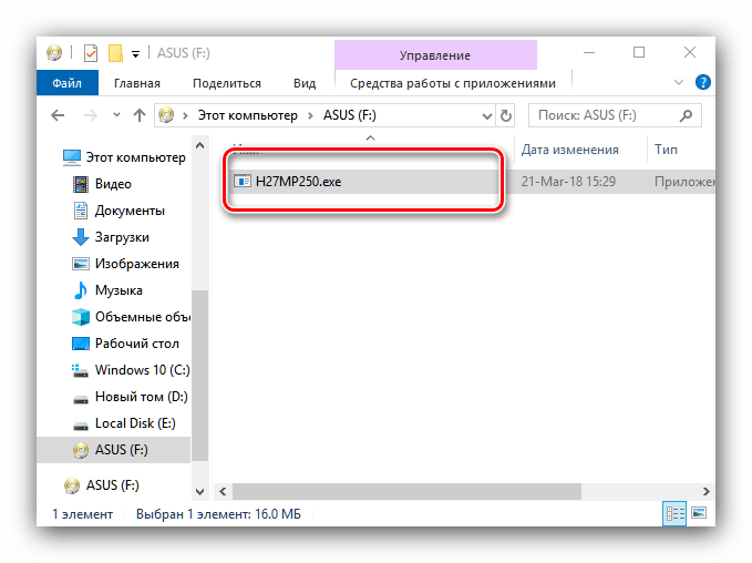
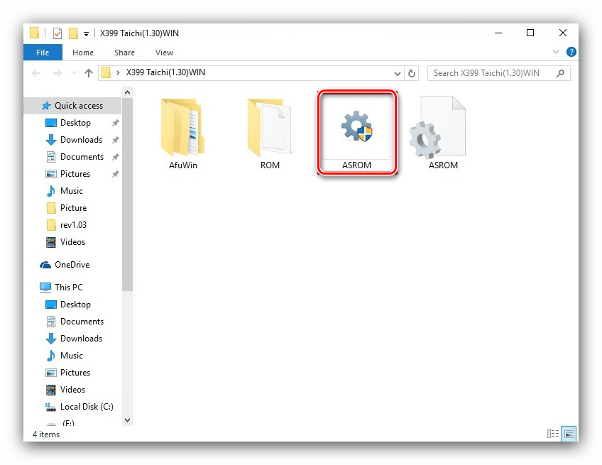
- Распакуйте архив с обновлениями в любую папку хранилища целевого компьютера. Найдите EXE-файл с обновлениями и запустите его от имени администратора.
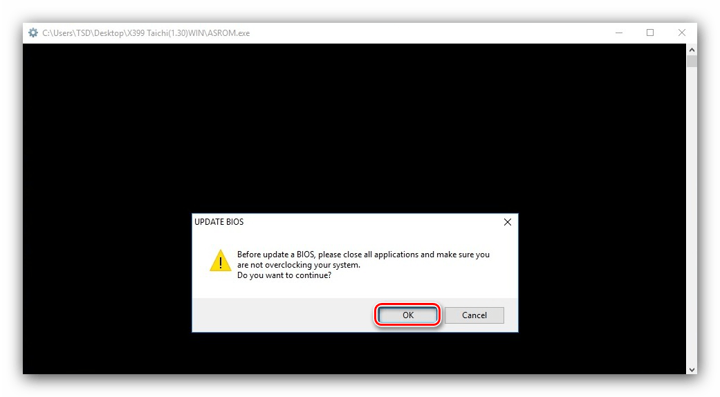
- Подождите, пока файл подготовит обновления. Через некоторое время появится предложение закрыть все программы, нажмите «ОК».
- Далее понадобится сделать рестарт для установки апдейтов, нажмите на клавишу Y на клавиатуре.
- Компьютер перезагрузится и начнётся процедура обновления. По её окончании повторите шаги 6-7 предыдущей инструкции.
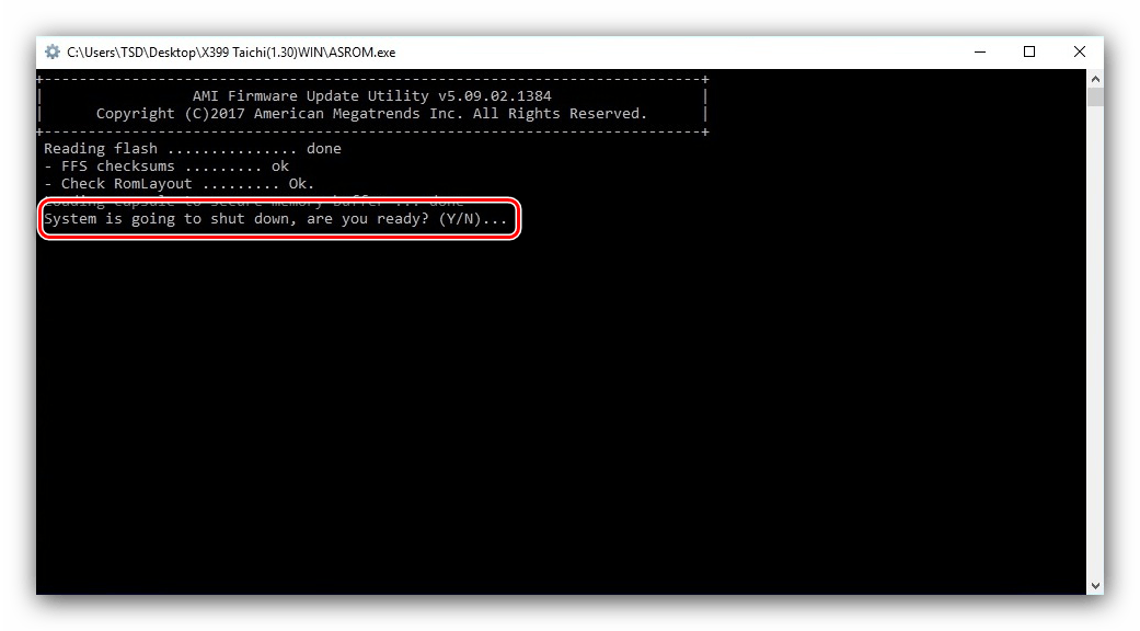
Технически этот метод подобен обновлению через DOS-оболочку, но не требует использования внешнего носителя. С другой стороны, существует ограничение совместимости по операционной системе, поэтому универсальным этот способ не назовёшь.
Заключение
Мы рассмотрели поэтапное выполнение процедуры обновления BIOS на материнских платах ASRock. Эта операция, как и подобные манипуляции с микропрограммой основной платы, требуют внимательности от пользователя и тщательного следования предложенным инструкциям.