
Manual
View the manual for the Yaesu FT5DR here, for free. This user manual comes under the category walkie talkies and has been rated by 1 people with an average of a 7.3. This manual is available in the following languages: English. Do you have a question about the Yaesu FT5DR?
Ask your question here
Yaesu FT5DR specifications
Below you will find the product specifications and the manual specifications of the Yaesu FT5DR.
The walkie talkie Yaesu FT5DR is a handheld communication device used for two-way radio communication. It operates on a specific frequency range and is commonly used by amateur radio operators, emergency response teams, and outdoor enthusiasts for communication over short distances. The Yaesu FT5DR has a compact and durable design, making it suitable for use in various environments and situations. It typically comes with a rechargeable battery that provides an extended operating time.
The walkie talkie Yaesu FT5DR features a push-to-talk button for transmitting messages and a built-in speaker for receiving messages. It also has a display screen that shows information such as the current channel, signal strength, and battery level. The device may also include additional features such as a built-in flashlight, weather channels, and emergency alert capabilities.
Overall, the walkie talkie Yaesu FT5DR is a reliable communication tool that can be used for a variety of purposes. Its portable and robust design, along with its essential features, make it a popular choice among users who require instant and reliable communication in their activities.
General
Frequently asked questions
Can’t find the answer to your question in the manual? You may find the answer to your question in the FAQs about the Yaesu FT5DR below.
Is the manual of the Yaesu FT5DR available in English?
Yes, the manual of the Yaesu FT5DR is available in English .
Is your question not listed? Ask your question here

C4FM/FM 144/430MHz
DUAL BAND DIGITAL TRANSCEIVER
FT5DR
FT5DE
Operating Manual

Contents
Introduction …………………………………………….. 2
Quick Guide ……………………………………………. 3
Controls & Connections ………………………….. 4
Transceiver ……………………………………………. 4
Operation Keys ……………………………………….5
Changing the Transceiver settings ……………. 5
Touch Screen Display …………………………….. 6
Safety Precautions (Be Sure to Read
Supplied Accessories and Options …………15
Supplied Accessories ……………………………. 15
Available Options………………………………….. 15
Preparation……………………………………………. 16
Installing the Antenna ……………………………. 16
Installing the Battery Pack …………………….. 16
Attaching the Quick Release Holster ………. 16
Attaching the Belt Clip …………………………… 16
Charging the Battery Pack……………………… 17
Charging the Batter y Pack using
the Battery Charger (SAD-25) … 17
Charging the Batter y Pack using
the Rapid Charger (CD-41) … 17
External Power Supply…………………………… 18
Connecting an External Power Supply
for Use in a Vehicle … 18
Connecting to an External Power Supply
Using a Power Cable … 18
Using a microSD Memory Card ………………. 18
Usable microSD Memory Cards …………….. 18
Mounting and Dismounting
microSD Memory Card …… 18
Formatting a microSD Memory Card ………. 19
Operation ………………………………………………. 20
Turning the Transceiver ON …………………… 20
Adjusting the Volume Level …………………….20
Adjusting the squelch setting …………………. 21
Toggling the Operating Band …………………. 21
Selecting a Frequency Band …………………..22
Tuning to a Frequency …………………………… 22
Changing the Frequency Step…………………23
Selecting the Communication Mode ……….. 23
Transmission ………………………………………..24
Changing the Transmit Power Level ……….. 25
Locking Keys and DIAL knob …………………. 25
Using the convenient Digital C4FM feature
About the Digital Group ID (DG-ID) feature
Communicating with the DG-ID feature …… 26
Repeater Operation ……………………………….. 29
Communicating Via the Repeater …………… 29
Using the Memory …………………………………. 30
) …….. 12
… 26
… 26
Registering to Memory Channels……………. 30
Recalling a Memory Channel …………………. 31
Recall only memories in the same frequency
band (Band) using the
memory auto grouping (MAG) function ……. 31
Clearing Memories ……………………………….. 32
Restored erased memory ……………………….32
Using Memory Tag ………………………………..32
Recalling the Home Channels…………………33
Changing the Home Channel Frequency ….33
Memory Channel List ……………………………. 33
Split Memory ………………………………………..33
Using Memory Bank ……………………………… 33
Memory Only Mode ………………………………. 33
PMG (Primary Memory Group
Activity Monitor) ………..34
Register the frequency with PMG …………… 34
Touch the bar graph to switch the frequency
Unregister the channel (frequency)
registered in PMG….. 35
Disable the PMG function ……………………… 35
CAM (Channel Activity Monitor) function … 36
Register memory channel to CAM group …. 36
Using the CAM function ………………………… 38
Touch the bar graph to switch the frequency
Change the displayed CAM group ………….. 38
Delete a registered memory channel
from CAM group … 39
Delete all the contents
in the CAM group at once …………… 40
Changing the name (tag) of CAM group ….. 40
Disable the CAM function………………………. 41
Band Scope …………………………………………… 42
Scanning Function ………………………………… 43
VFO Scan ……………………………………………. 43
Memory Channel Scanning ……………………. 43
Setting the Receive Operation
When Scanning Stops ……..44
Weather Alert Scan ………………………………. 44
Skip Memory Channels, and
Specied Memory Channels ……….. 45
Programmable Memory scan (PMS) ………..45
Dual Receive (D.RCV) feature ……………….. 45
Convenient Functions ……………………………. 46
Bluetooth
VOX Operation ……………………………………..50
Convenient Preset Receiver
Memory Channels …………. 52
Using the Voice Recording ……………………..56
Taking Pictures (Snapshot Function) ……….58
®
Operation …………………………….. 46
… 35
… 38

GPS Function ………………………………………. 59
WIRES-X function …………………………………60
APRS (Automatic Packet
Reporting System) function ………60
Tone squelch feature …………………………….. 61
Digital Code squelch (DCS) feature ………… 61
New PAGER (EPCS) feature………………….. 61
Digital Personal ID (DP-ID) feature …………. 61
Using Setup Menu …………………………………. 62
Setup Menu Operation …………………………..62
Tables of Setup Menu Operations ……………63
Restoring to Defaults (Reset) …………………. 69
All Reset ……………………………………………… 69
Setup Menu Reset ………………………………… 69
Text input screen ……………………………………70
……………………………………….. 72
YAESU LIMITED WARRANTY ………………….74
1

Introduction
Features of the Yaesu FT5DR/DE Transceiver.
Digital communication using Yaesu (C4FM (Quaternary FSK) system).
m
Equipped with AMS (Automatic Mode Select) Function.
m
The AMS (Automatic Mode Select) feature automatically selects the analog FM and
C4FM digital modes, according to the signal of the other station.
The DG-ID (Digital Group ID) feature, and the Group Monitor (GM) feature enable au-
m
tomatically locating, and communicating with other stations within contact range, that
have the matching DG-ID number, (Group ID number from 00 to 99).
Full color 320×240 dot LCD, high resolution TFT touch panel display.
m
The communication status and settings of the FT5DR/DE are displayed in a straightforward manner, achieving excellent operability.
Equipped with Bluetooth
m
Supports hands-free communication using the optional Bluetooth
BT10 or a commercially available product.
WIRES-X connection support.
m
Supports WIRES-X portable digital node function.
m
Equipped with GM function.
m
Digital Personal ID (DP-ID) feature.
m
Simultaneous reception of two separate frequencies, on different bands, or within the
m
same band (V+V/U+U).
Wide-band reception (520kHz to 999.995MHz) (USA Cellular Blocked)).
m
Waterproof design equivalent to IPX7, which protects the transceiver from rain and
m
splashes.
Built-in GPS unit permitting display of the current location and heading information.
m
Large-capacity 1256 memory channels.
m
The Memory Auto Grouping (MAG) function allows automatic grouping and recalling
m
only memory channels in the same frequency band.
Register frequently used frequencies into the PMG (Primary Memory Group
m
Activity Monitor), and then pressing the [PMG] key will display the registered frequency status (signal strength) in a bar graph (up to 5 channels). You can instantly
move to that channel by simply touching the bar graph (TOUCH & GO Operation).
Display memory tags comprised of up to 16 alpha/numeric characters.
m
Convenient reception of preset receiver memory channels.
m
A wide variety of scan features.
m
Ready for APRS
m
®
(B-band only).
High-resolution band scope that displays 79 channels.
m
Smart Navigation function.
m
Snapshot function (optional camera/microphone MH-85A11U is required).
m
A variety of individual Selective Calling functions (Tone Squelch (CTCSS) and DCS
m
etc.).
Compatible with microSD memory cards.
m
Thank you for purchasing the FT5DR/DE Transceiver. We urge you to read this manual
in its entirety, and also the Advance Manual (available for download on the Yaesu website), to gain a full understanding of the amazing capability of the exciting new FT5DR/
DE Transceiver.
WIRES-X, GM function and APRS instruction manuals are not included in the product
package. They are available and may be downloaded from the Yaesu.com website.
®
The Bluetooth
wordmark and logo are registered trademarks owned by Bluetooth SIG,
Inc. and are used under license by Yaesu Musen Co., Ltd.
®
function as standard.
®
headset SSM-
communication with world standard 1200 / 9600bps AX25 modem
2

Please enter your
Callsign.
(Max 10 letters)
Quick Guide
① Turning the Power ON
Install the charged battery pack and then
press and hold the Power switch.
② Inputting the Call sign
When turning the power ON for the first
time after purchasing, input the call sign of
your own station.
Input call sign may be changed from Setup
Menu [CALLSIGN] (page 68).
1. When turning the power ON for the first
time after purchasing, the call sign input
screen will be displayed.
2. Press the [F ] key.
3. Input the call sign.
Rotate the DIAL knob to select each
character.
Touch
right.
4. Repeat step 3 to input the remaining
call sign characters.
Touch
Touch
cursor position.
5. Press the PTT switch to conclude inputting.
Normal operation (VFO Mode) screen
will be displayed.
to move the cursor to the
to move the cursor to the left.
to erase the character at the
③ Selecting the Operating Band
Press the [BAND] key.
④ Tuning the frequency
Rotate the DIAL knob.
⑤ Adjusting the volume
Rotate the VOL knob to adjust the volume
to a comfortable level.
⑥ Adjusting the squelch setting
The squelch level may be adjusted to mute
the background noise when no signal is
received.
1. Press the SQL key.
2. Rotate the VOL knob to adjust the
squelch to a level at which the background noise is muted.
* When the squelch level is increased,
the noise is more likely to be silenced,
but it may become more difficult to
receive weak signals.
3. Press the SQL key to save the setting.
⑦ Selecting the
Communication Mode
The communication mode is automatically
selected to correspond to the signal being
received.
Touch [MODE] to manually select the communication mode.
⑧
Transmitting/Receiving Signals
Transmitting
While pressing and holding the PTT
switch, speak into the microphone.
Receiving
Release the PTT to return to receive
mode.
Set the Bluetooth® function
The FT5DR/DE equipped with the Bluetooth function. To use a Bluetooth
set, refer to “Bluetooth
page 46 for setting.
®
Operation” on
®
head-
3

Controls & Connections
Transceiver
Antenna jack (SMA)
TX/BUSY LED
①
PTT Switch
②
MONI/T-CALL
③
key
SQL key
④
Power( )Switch
⑤
TX/BUSY LED
Lights blue (C4FM digital) or green (Analog
FM) during receive and lights red during
transmit. Blinks while receiving a signal that
does not match the DG-ID or similar tones.
PTT Switch
Press and hold the PTT switch to transmit,
and release it to receive.
MONI/T-CALL key
Press to return to the previous screen.
USA/Asian version
European version
SQL key
Press the SQL switch, then rotate the VOL
knob to
Power (Lock) Switch
• When the power is OFF, press and hold
• When the power is ON, press and hold
• When the power is ON, press this button
DIAL knob
Rotate the DIAL Knob to change the frequency or select a memory channel.
VOL knob
Rotate the VOL Knob to adjust the audio
volume level.
Press the MONI/T-CALL key to open the
squelch.
Press the MONI/T-CALL key to activate
the T-CALL (1750 Hz).
adjust the squelch level.
this switch to turn the Power ON.
the switch again to turn the Power OFF.
briefly to engage, or release the key lock.
DIAL knob
⑥
VOL knob
MIC/SP jack
Full Color
Touch screen
display
Operation Keys
Speaker
MIC/SP jack*
Connect the optional speaker microphone
or earpiece microphone to this jack.
When an external microphone or cable is
connected, the dust and splash protection
does not function.
Do not connect any microphone which
is not specified by Yaesu.
DATA Terminal*
• Connect the optional camera-equipped
microphone (MH-85A11U) to this terminal.
• To use the clone function, connect to another FT5DR/DE with an optional clone
cable (CT-168).
• When updating the firmware, connect to a
PC using a USB cable.
* For instructions to update the firmware,
access the Yaesu Website.
• An external GPS may be connected to
this terminal.
microSD memory card slot*
EXT DC IN jack*
• When charging the battery pack, connect
the battery charger (SAD-25) to this jack.
• Connect an external power supply adapter
with a cigarette lighter plug (SDD-13) or an
external power cable (E-DC-6) to this jack.
Do not connect any battery charger
which is not specified by Yaesu.
* When the included antenna and battery pack
are installed and the MIC/SP jack, DATA terminal, microSD card slot and EXT DC IN jack
are securely covered with rubber caps, the
FT5DR/DE meets the waterproofing performance conforming to IPX7.
⑦
DATA Terminal
⑧
⑨
card slot
EXT DC IN jack
⑩
Battery Pack
4

Operation Keys
F key
A/B key
BAND key
key
V/M key
PMG key
BACK key
Pressing each time switches between
function screen and normal screen.
Pressing each time switches between
A-band and B-band.
Pressing each time increases the frequency band.
Press to turn the GM function ON/
OFF.
Pressing each time switches between
VFO mode and memory mode.
Pressing each time switches between
PMG (Primary Memory Group Activity
Monitor) mode and memory or VFO
mode.
Return to the previous screen. —
Press Press and Hold
Press and hold for over one second to
enter Setup Menu.
Press and hold for over one second
to switch between the Dual Band
Receive mode and the Mono Band
Receive mode.
—
In normal mode, press and hold for
over one second to start WIRES-X.
When WIRES-X is activated, press
and hold for over one second to return
to the normal mode.
Press and hold for over one second to
write to memory.
Press and hold for over one second to
writing to PMG memory.
Changing the Transceiver settings
1. Press and hold the [F ] key.
The SETUP MENU screen will be displayed.
2. Touch the desired item in Setup Menu.
The Sub-menu screen will be displayed.
May also be operated by rotating the DIAL knob
to select the desired item in Setup Menu, and then
press the [F ] key.
3. Press the PTT switch to save the settings and return
to normal operation.
Press the [BACK] key to save the settings and return
to the previous screen.
5
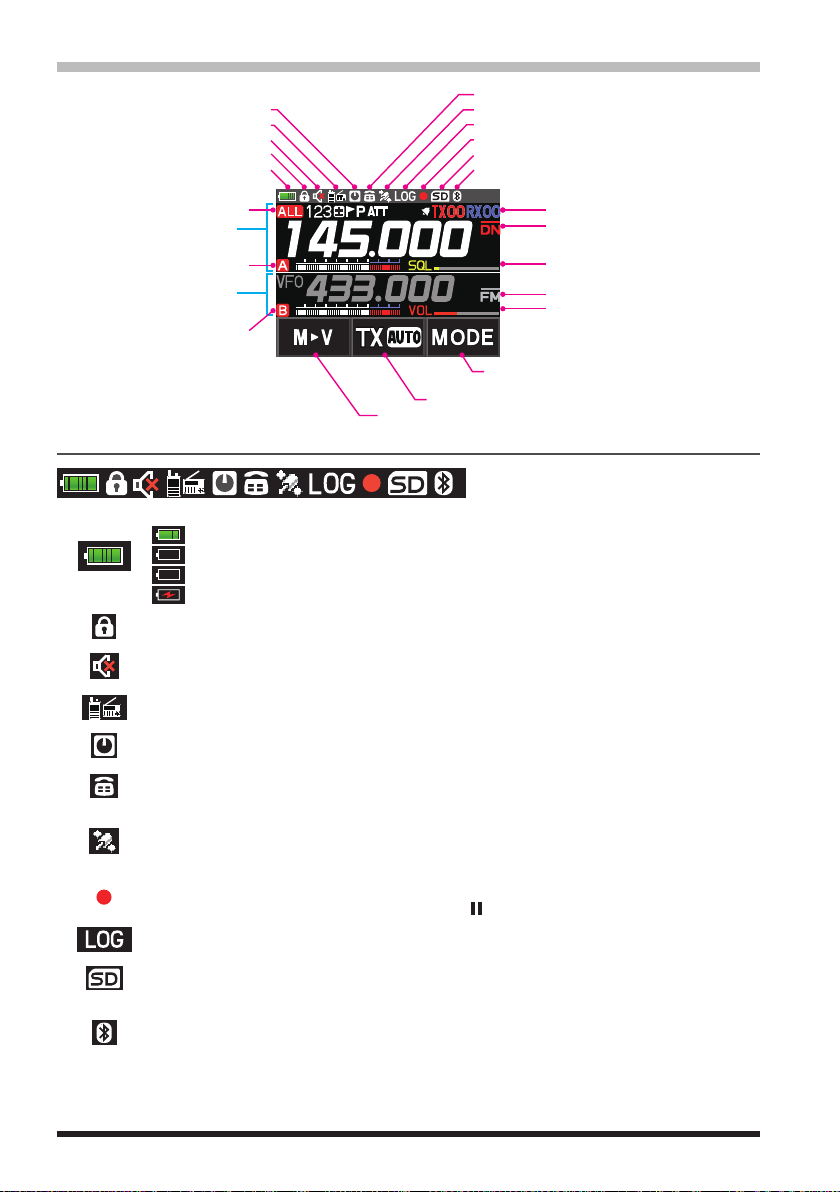
Touch Screen Display
Lights when DTMF function is enabled
Touch and hold: Moving Memory Data to the VFO register
Lights when Auto Power Off is active
Lights when AF DUAL Function is enabled
Lights when the mute Function is active
Displays mode
A-band display area
B-band display area
LOCK
Battery condition
A-band icon
B-band icon
Status Bar
The battery condition is displayed in 8 steps.
: Full battery power
: Battery is depleted. Charge battery.
(When blinking) Charge battery immediately.
:
Charging (displayed when the power is ON).
:
Appears when the lock function is enabled.
Appears when the Mute function for B-band is enabled.
Lights when GPS is acquired
Lights when GPS Log Function is enabled
Lights when the Voice memory function is enabled
Lights when a microSD memory card is inserted
Lights when Bluetooth function is active
Display of settings such as DG-ID/TONE
Communication Mode
Squelch/Volume Bar Graph (A-band)
Displays operation mode
Squelch/Volume Bar Graph (B-band)
Communication mode selection (AMS/DN/VW/FM)
Communication mode selection at AMS (TX AUTO/TX FM/TX DN)
Appears when the AF DUAL function is enabled.
Appears when the APO (Automatic Power-Off) function is enabled.
Appears when the DTMF Autodialer function is activated.
Appears when the Built-in GPS function is activated.
Appears: Satellites are acquired.
Blinks: Satellites cannot be acquired.
Appears when the Voice recording function is activated (About 3 seconds after the
squelch closes, the recording pauses and a “ ” appears.).
Appears when the GPS Log function is enabled.
Appears when a microSD card is inserted.
Appears when the Bluetooth® function is activated.
Appears: Bluetooth® device is connected.
Blinks: Bluetooth® device not connected.
6

A-band / B-band display area
A-band / B-band display modes
: VFO mode
: PMG mode (Recalls only the frequencies registered in PMG)
: Memory mode (The numeric is the memory channel number)
Press the BAND key while in memory mode, the MAG function can automatically recall memory channels in groups for each of the following bands: (For
details, refer to “Using the Memory” on page 30.)
/ / / / / / /
: Home Channel
VDR : VFO Dual Receive (VFO ↔ Priority Memory Channel)
MDR :
Memory Channel Dual Receive (Memory Channel
HDR : HOME Channel Dual Receive (HOME Channel ↔ Priority Memory Channel)
: Repeater minus (-) shift
: Repeater plus (+) shift
: Split operation
Specified Memory Channel (Specify that only designated memory channels are
scanned during memory scanning.)
Skip Memory Channel (Permits designating unwanted channels to be skipped during
scanning.)
Priority Memory Channel (The transceiver checks for signals on the frequency registered to the selected Priority Memory Channel, once every 5 seconds.)
ATT (attenuator) function (When the desired signal is extremely strong, activate the
attenuator to reduce the incoming signal from the antenna.)
↔
Priority Memory Channel)
Bell function is activated.
TX/RX DG-ID is displayed
TXnn (The transmit DG-ID number), RXnn (The receive DG-ID number)
Squelch type is displayed (For additional details, refer to the Advanced Manual.)
: Tone Encoder (tone frequency is displayed)
: Tone Squelch (tone frequency is displayed)
: DCS (Digital Code Squelch) (DCS code is displayed)
: Reverse Tone (tone frequency is displayed)
: Signal Squelch
: Pager (EPCS)
The following can be set when the squelch expansion (see page 64) is on.
: Send the DCS code only during transmission.
: Send the CTCSS tone signal during transmit, and wait for the DCS code in
receive mode. (tone frequency is displayed)
: Send the DCS code during transmit, and wait for the CTCSS tone signal in
receive mode. (tone frequency is displayed)
7
Displays the operating mode (Digital mode is indicated by a red icon)
: FM (Analog) mode
: Normal digital mode (digital mode using C4FM modulation)
: Wide digital mode (digital mode using C4FM modulation)
: Data FR mode (data communication mode using C4FM modulation)
: AMS (Automatic Mode Select) FM (Analog) mode
: AMS (Automatic Mode Select) DN mode
: AMS (Automatic Mode Select) VW mode
: AMS (Automatic Mode Select) DW mode
When AMS (Automatic Mode Select) function is activated, indicator is shown with a
bar appearing above the mode. The transceiver automatically switches to the DW
mode during image transmission.
: A-band icon
: B-band icon
: S meter (Displays received signal strength in 10 levels)
: Volume level
: SQL level
Touch keys display area
MODEMODE
Touch and hold: Moving Memory Data to the VFO register.
Each touch steps the transmit communication mode as follows:
TX (AUTO):
TX (FM):
TX (DN):
Each touch steps the communication mode as follows:
The current communication mode is displayed on the upper right of the frequency.
MODEMODE
*1 The AMS (Automatic Mode Select) function displays one of the
the automatically selected communication mode.
*2 When the Setup Menu item [TX/RX] [2 DIGITAL] [4 DIGITAL VW] is set to “ON”
(factory default is “OFF”), the Voice FR (VW) may be selected.
Automatically selects the transmit mode to correspond to the received signal.
Always transmits in the analog FM mode.
Always transmits in the digital (DN) mode.
/ / )
(
/ /
AMS function operation (A bar is displayed at the top of the communication
mode icon, and the AMS function automatically displays the selected communication mode.)
: V/D Mode (Voice/Data simultaneous transmission mode)
2
*
Wide digital mode (high-quality digital communication)
:
FM (Analog) mode
:
: PO meter (Displays transmit output in 4 levels when transmitting)
TX (AUTO)
1
*
:
1
*
TX (FM)
TX (DN)
*
2
( / / )
TX (AUTO)
• • •
1
*
/ / icons for
• • •
8
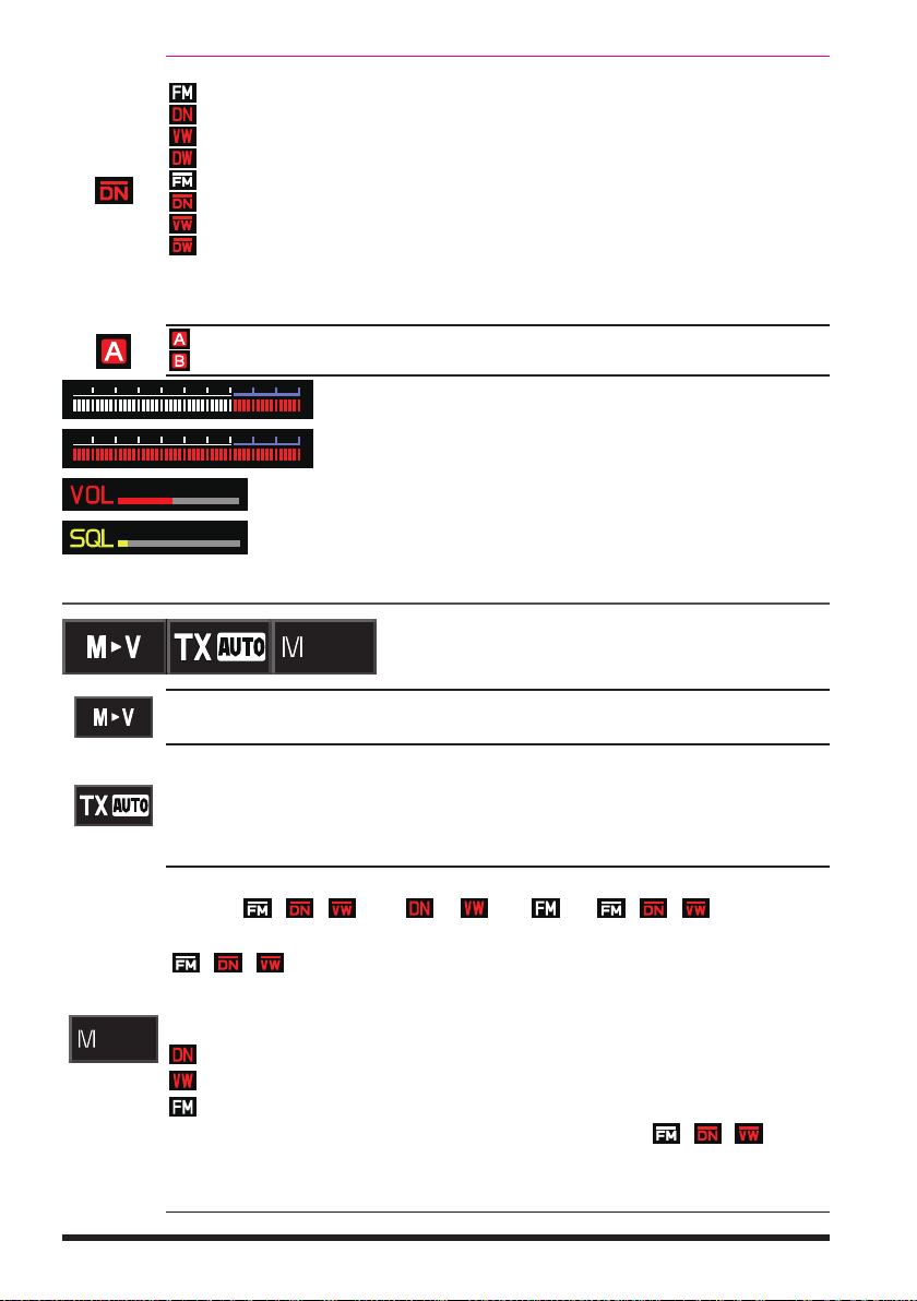
●Dual Band Screen
A-band and B-band are displayed in a top-down fashion.
Both bands are received simultaneously.
Touch and hold the frequency of the operation band
(white display) to display the numeric keypad screen for
frequency input.
Touch the sub-band (gray display) frequency to change
the operation band.
When both the operation band and the sub-band are re-
ceiving signals at the same time, the audio on the subband receiver is automatically muted. Setup Menu: [TX/
RX] [3 AUDIO] [2 MUTE]: Allows setting the
muting level.
Press and hold the [A/B] key.
●Mono Band Screen
A-band or B-band is displayed.
Receives only the displayed band.
Touch and hold the frequency to display the numeric
keypad screen for frequency input.
The memory tag and battery voltage etc. are displayed
on the lower segment.
●Function Menu Screen (Press the [F ] key)
Press the [F ] key to displays the function menu screen.
Press the [BACK] key to return to the previous screen.
There are two function menus. Touch [FWD ] or [BACK
display to switch the screens.
Depending on the communication mode and settings, some functions may not operate
when the Menu item is touched.
Function Menu Screen 1
Touch
Touch
] at the bottom right of the
Function Menu Screen 2
9

●PGM (Primary Memory Group Activity Monitor) Screen (Press the [PMG] key)
Up to 5 frequencies registered in PMG are displayed, and the signal strength received
by each channel is displayed as a bar graph.
Touch the bar graph to instantly switch the receiver to
that frequency.
Information on the selected channel is displayed at the
top of the screen, and you can transmit immediately by
pressing PTT.
●CAM (Channel Activity Monitor) Screen (Press the [F] key
Frequencies that are often used with friends can be registered to the CAM group memory channels, and then displayed on the CAM screen. The signal status and strength of
each channel in the selected group are shown in a bar graph.
Touch the bar graph to instantly switch the receiver to
that frequency.
CAM Group: Up to 10 groups, with up to 5 memory
chan- nels each, can be registered in each group.
●Band Scope Screen (Press the [F ] key
In VFO mode, the Band Scope searches the channels above and below the center receive frequency at high speed. The signal strengths are displayed on a graph, so the
presence or absence of a signal on any channel is easily noted.
The frequency may be changed by turning the DIAL
knob.
Touch [SEARCH] or [STOP] to begin or stop the search.
The number of channels to search in Band Scope may
be set to 19, 39 or 79. (See “Change the number of
channels displayed” page 42).
To end the Band Scope function, press the [BACK] key.
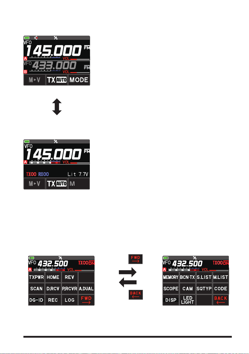
●GM (Group Monitor) Screen (Press the [GM/X] key)
Automatically listens for stations operating with GM function on the same frequency,
that are within the communication range, and displays the call sign, direction, distance,
within / outside. For details, refer to the separate GM Instruction Manual which is available on the Yaesu website.
The call signs of the stations that can communicate is
displayed in white characters.
The call signs of stations outside the sphere of commu-
nications are displayed in gray characters.
Touch [APL], to display the positions of multiple mem-
ber stations on the compass screen, centered on your
own station.
Touch [LOG] to view previously sent or received mes-
sages and photos.
To end the GM function, press the [GM] key.
Touch [SCOPE])
Touch [CAM])
10
●AF DUAL Screen (Press the [F] key Touch [A.DUAL])
While receiving and listening to a radio broadcast, the A-band and B-band may also be
monitored simultaneously for activity.
When a signal is received on A-band or B-band, the
broadcast audio is muted and the A or B band audio is
heard.
To end the AF DUAL function, press the [BACK] key.
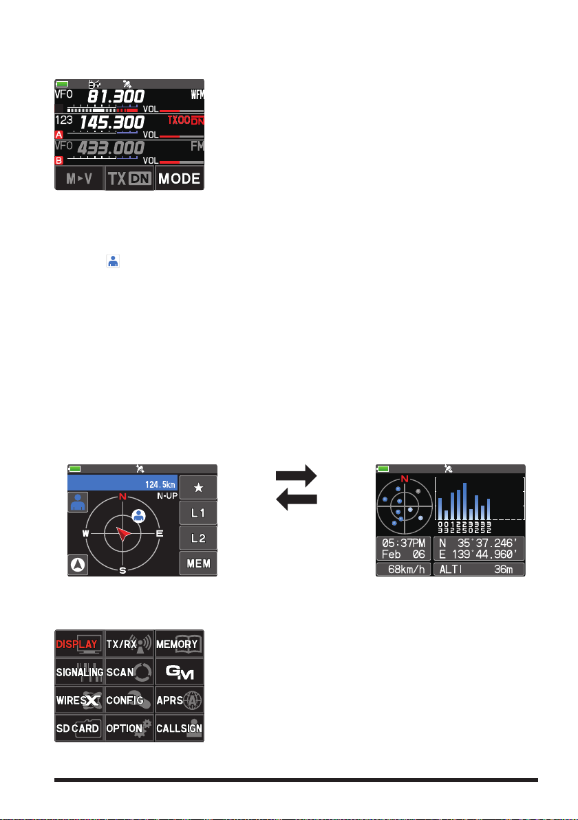
●BACKTRACK Screen (Press the [F ] key
Touch [DISP])
The backtrack screen, or the GPS information screen, whichever was displayed last, will
be displayed.
Real-time navigation function
Touch [
] at the top left of the screen to display the position and direction of the partner station in real time during communication in C4FM digital V/D mode. (The signal
of the partner station must contain location information.)
BACKTRACK function
May register the departure point etc. up to 3 places (“H”, “L1”, “L2”) in advance and
display the distance from the current location to the registered point in real time.
●GPS Information Screen (Press the [F ] key
Touch [DISP])
The backtrack screen, or the GPS information screen, whichever was displayed last, will
be displayed. The GPS satellites status and numbers are shown.
The following information is displayed.
Direction and elevation of satellites, and their signal strengths
Current time and date
Moving Speed
Backtrack Screen
●
Current latitude and longitude
●
Altitude of current location
GPS Information Screen
Touch the screen (other
than the Touch keys).
●SETUP MENU Screen (Press and hold the [F] key)
Setup Menu allows selecting various functions from the displayed list and setting the
parameters of each function according individual preferences.
Press the PTT switch or press the [BACK] key several
times to exit the Setup Menu.
11
Safety Precautions (Be Sure to Read
)
Be sure to read these important precautions, and use this product safely.
Yaesu is not liable for any failures or problems caused by the use or misuse of this product by the purchaser or any third party. Also, Yaesu is not liable for damages caused
through the use of this product by the purchaser or any third party, except in cases
where ordered to pay damages under the laws.
Types and meanings of the marks
DANGER
WARNING
CAUTION
This mark indicates an eminently hazardous situation, which, if not avoided,
could result in death or serious injury.
This mark indicates a potentially hazardous situation, which, if not avoided,
could result in death or serious injury.
This mark indicates a potentially hazardous situation, which, if not avoided,
may result in minor or moderate injury or only property damage.
Types and meanings of symbols
These symbols signify prohibited actions, which must not be done to use this product safely.
For example: indicates that the product should not be disassembled.
These symbols signify required actions, which must be done to use this product safely.
For example:
indicates that the power plug should be disconnected.
DANGER
Do not use this product in an area where RF
transmitters are prohibited, e.g., inside of a
hospital, airplane, or train.
This product can affect electronic or medical devices.
Do not transmit with this device while carrying or using a medical appliance such as a
cardiac pacemaker. When transmitting, use
an external antenna and keep as far as possible away from the external antenna.
The radio wave emitted by the transmitter can
cause the medical device to malfunction and
result in injury or death.
Do not transmit with this device in a crowded
place for the safety of persons using a medical device such as a cardiac pacemaker.
The radio wave emitted from this product can
cause the medical device to malfunction and
result in injury or death.
Do not use this product or the battery charger anywhere inflammable gas is produced.
A fire or explosion can occur.
If thunder and lightening develop nearby
when an external antenna is used, immediate
ly turn this transceiver OFF, and disconnect
the external antenna from it.
A fire, electrical shock, or damage may result.
Do not use this product while riding a bicycle
or driving a car. Accidents can result.
Be sure to stop the bicycle or car at a safe place
before using this product.
Do not touch any material leaking from the
LCD display or the battery pack with bare
hands.
The chemical may adhere to your skin or enter
your eye, and cause chemical burns. In such a
case, consult the doctor immediately.
Do not solder or short-circuit the terminals
of the battery pack.
A fire, leak, overheating, explosion, or ignition
may result.
Do not carry the battery pack together with a
necklace, hairpin, or small metal objects. A short
circuit can result.
—
Do not disassemble or make any alteration
to this product.
An injury, electric shock, or failure may result.
Do not handle the battery pack or charger
with wet hands. Do not insert or remove the
power plug with wet hands.
An injury, leak, fire, or failure may result.
12
WARNING
Do not power this transceiver with a voltage
other than the specified power supply voltage.
A fire, electric shock, or damage may result.
Keep the terminals of the battery pack clean.
If terminal contacts are dirty or corroded, a fire,
leak, overheating, explosion, or ignition can result.

If smoke or a strange odor is emitted from
the main body, battery pack, or battery charger, immediately turn the transceiver off;
remove the battery pack, and remove the
power plug from the outlet.
A fire, chemical leak, overheating, component
damage, ignition, or failure may result. Contact
the dealer from which you purchased this product
or Yaesu.
Do not bend, twist, pull, heat or modify the
power cord and connection cables in an unreasonable manner.
This may cut or damage the cables and result in
fire, electric shock and equipment failure.
Do not pull the cable when plugging and
unplugging the power cord and connection
cables.
Always hold the plug or connector when unplugging; if not, a fire, electric shock and equipment
failure may result.
Do not use the device when the power cord
and connection cables are damaged, or when
the DC power connector cannot be plugged
in tightly.
Contact Yaesu or the retail store where this
transceiver was purchased for assistance, as
this may result in fire, electric shock and equipment failure.
Do not install the transceiver or the wire cables near the automobile air bags.
In case of an accident, the transceiver may
interfere with air bag deployment and result in
extreme injury. The wire cables may also cause
the air bag to malfunction.
Do not make very long transmissions.
The main body of the transceiver may overheat,
resulting in component failure or operator burns.
Do not place the transceiver in wet or damp
areas (e.g. near a humidifier).
This may result in fire, electric shock and equipment failure.
Do not use DC power cords other than the
one enclosed or specified.
This may result in fire, electric shock and equipment malfunctions.
When connecting a DC power cord, be certain the positive and negative polarities are
correct.
Reverse connection will result in equipment
damage.
When transmitting, keep the transceiver at
least 5.0 mm (3/16 inch) away from your body.
Use only the supplied antenna. Do not use
modified or damaged antennas.
Disconnect the power cord and connection
cables before installing separately sold accessory items.
This may result in fire, electric shock and equipment failure.
Follow the instructions provided when installing items sold separately.
This may result in fire, electric shock and equipment failure.
Use only the provided or specified screws.
Using screws of a different size, may result in
fire, electric shock and component damage.
Do not place the transceiver in a confined
space, such as a bookshelf which is not ventilated well.
This may result in overheating and fire, electric
shock and equipment failure.
Do not operate the transceiver on a carpet or
a blanket.
This may result in overheating and fire, electric
shock and equipment failure.
If a foreign substance is spilled into the
transceiver, turn it OFF immediately and remove the power plug from the outlet.
If used as it is, a fire, electrical shock, or damage may result.
CAUTION
Do not place the transceiver on an unsteady
or sloping surface, or in a location with extreme vibration.
The transceiver may fall or drop, resulting in fire,
injury and equipment damage.
Do not place this transceiver in a humid or
dusty place.
A fire or failure may result.
Do not use the transceiver near the radio relay equipment.
Transmissions may affect radio communication.
Do not wipe the case using thinner and benzene etc.
Use only a soft, dry cloth to wipe stains from the
case.
Do not throw the transceiver, or subject it to
strong impact forces.
Physical abuse may result in component damage and equipment failure.
If the transceiver will not be used for an extended period, turn it OFF and remove the battery
pack for safety.
Keep magnetic cards and videotapes away
from the transceiver.
The data recorded on cash cards or videotapes
may be erased.
Do not place this transceiver in direct sunlight or near a heater.
The case may be deformed or discolored.
Do not operate the transceiver near the TV or
radio.
Radio disturbance can occur in the transceiver,
the TV, or the radio.
13

Be sure to check with the manufacturer of
any hybrid or fuel-saving automobile regard
ing use of the transceiver in that car.
Noise generated by an onboard electrical device
(
inverter, etc.) can disrupt the normal operation
of the transceiver.
Do not transmit near the television and radio.
Transmissions may cause electromagnetic interference.
While transmitting, keep the antenna as far
from you as possible.
Long-time exposure to electromagnetic waves
may have a negative impact on your health.
Do not dangle or throw the transceiver by
holding its antenna.
This may injure others and may also result in
damage and failure of the transceiver.
Do not use the transceiver in a crowded
place.
The antenna may strike others and result in an
injury.
Keep this product out of the reach of children.
Injury to the child, or damage to the transceiver
may result.
—
Do not use any products other than the specified options and accessories.
Failure or miss operation may result.
Install the hand strap and belt clip securely.
Improper installation may cause the FT5DR/
FT5DE to fall or drop, resulting in an injury or
damage.
This product has a waterproof structure and
conforms to “IPX7” when the included antenna and battery pack are installed and rubber
caps are securely attached to the MIC/SP
jack, EXT DC IN jack, and DATA terminal. If
this transceiver gets wet, dry it with a soft
cloth, do not leave it exposed to the moisture.
Exposure to excessive moisture may degrade
the transceiver performance, shorten its life, or
cause a failure or electrical shock.
Before discarding a depleted battery pack, affix
tape or insulating covering to its terminals.
Do not use at extremely low atmospheric pressure.
About Waterproofing Feature Conforming to IPX7
When the included antenna and battery pack are installed and the MIC/SP jack, EXT
DC IN jack, DATA terminal, and microSD slot are securely covered with rubber caps,
this product is moisture and splash resistant. To ensure continued waterproofing protection, be sure to check the following points before use.
Check for damages, deterioration, and dirt.
m
Antenna rubber, key switch rubber, MIC/SP jack, EXT DC IN jack, DATA terminal, microSD
slot rubber cap, and battery pack joint.
Cleaning
m
When this product is contaminated with seawater, sand, or dirt, rinse with fresh water, and
then wipe with a dry cloth immediately.
Recommended maintenance interval
m
To ensure continued water resistance and optimal performance, it is recommended that
maintenance be performed annually, or when any damage or deterioration is found. Note that
the maintenance service is subject to fees.
Do not immerse this product in the following liquids:
m
Sea, pool, hot spring, water containing soap, detergent, or bath additive, alcohol, or chemicals.
Do not leave this product for an extended time in the following places:
m
Bathroom, kitchen, or humid place
Other precautions
m
Since this product is not totally waterproof, it cannot be immersed in water.
14

Supplied Accessories and Options
Supplied Accessories
• Rechargeable Li-Ion Battery Pack (7.2V, 2,200mAh) SBR-14LI
• Battery Charger SAD-25
• Antenna
• Belt Clip
• Quick Release Holster SHB-26BK
• USB Cable
• Operating Manual (This Manual)
• SBR-14LI Manual
• Battery Pack protective cap
If any item is missing, contact the dealer from which you purchased the transceiver.
Available Options
• Speaker Microphone with Snapshot camera MH-85A11U
• Speaker / Microphone SSM-17A
• Earpiece Microphone SSM-57A
• VOX Headset SSM-63A
• Bluetooth® Headset SSM-BT10
• Microphone Adapter CT-44
• DC Cable with and Cigarette-Lighter Plug SDD-13
• DC Cable E-DC-6
• Quick Release Holster SHB-26BK
• Soft Case SHC-40
• 3x “AA” Cell Battery Case FBA-39
• Li-Ion Battery Packs (7.2V, 2,200mAh) SBR-14LI
• Li-Ion Battery Packs (7.4V, 1,100mAh) FNB-101LI
• Battery Charger SAD-25
• Rapid Charger CD-41
• PC connection cable SCU-39
• Cloning Cable CT-168
• PC connection cable CT-169
• Data Cable CT-170
• Data cable (2.5) CT-176
• Belt Clip SHB-13
• BNC-to-SMA Adapter (BNCJ-SMAP) CN-3
15

Preparation
Supplied screws (black)
for the Quick release Holster
Supplied screws (silver)
for the Belt Clip
To remove the holster,
press the release knob.
②
Press holster firmly
slots on the bottom of the FT5DR/DE
Installing the Antenna
Turn the antenna clockwise until it is secured.
• Do not hold or twist the upper part of the antenna
when installing or removing it. To do so may break the
conductors inside the antenna.
• Do not key the transmit without installing the antenna. The
transmitter components may be damaged.
Installing the Battery Pack
1. Insert the bottom tabs of the battery pack in the slots on
the back side lower part of the transceiver.
2. Push the battery in until the battery latches click securely.
Charge the battery pack before using the transceiver for the
first time after purchase, or when it has not been used for a
long period time.
Risk of explosion if battery is replaced by an incorrect type.
Dispose of used batteries according to the instructions
●Removing the Battery Pack
While pressing down the latches, remove the battery pack.
Attaching the Quick Release Holster
Attach the quick release holster using the supplied screws (two).
until you hear the
latch click.
of the antenna
Attaching the Belt Clip
Attach the belt clip using the supplied screws (two).
Be sure to use the supplied screws when attaching the belt clip. If any other screws are used, the
belt clip cannot be secured firmly to the battery pack and the transceiver may drop off together
with the battery pack; the transceiver and battery pack may fall off, breakage and other damage.
16
Insert the bottom tabs of the Quick Release Holster in the

Charging the Battery Pack
Charging the Battery Pack using the Battery Charger (SAD-25)
Using the supplied battery charger (SAD-25), it takes about 9 hours* to charge the SBR14LI battery pack fully.
*Depending on the battery status, the charging time might be increased
1. Referring to the figure at the right, connect the
battery charger plugs.
When the battery is being charged, the TX/BUSY
Indicator of the A-band lights red, and “Now
Charging” is displayed. The charge level is indicated by a bar graph.
2. When charging is completed, the display will
change to indicate “CHGFUL” and the TX/BUSY
Indicator will light green.
While the transceiver power is ON, “
” will ap-
pear on the display.
In the USA Version, the TX/BUSY LED is not lit when charging or when charging is complete.
When the charge is complete, the transceiver turns OFF after 3 minutes.
• If “CHGERR” appears on the LCD during the charging and the battery pack is not charged
after a lapse of 10 or more hours, stop charging the battery pack immediately. The battery
pack is presumed to be at the end of its service life, or defective. In this case, replace the
battery pack with a new one.
• Charge the battery pack within the temperature range from +41°F to +95°F (+5°C to
+35°C).
Charging the Battery Pack using the Rapid Charger (CD-41)
The optional Rapid Charger (CD-41) requires about 5 hours to charge the SBR-14LI
battery pack.
1. Insert the DC plug from the SAD-25 into the DC jack on the CD-41 rear panel, then
plug the SAD-25 into the AC line outlet.
2. Place the transceiver with battery pack attached or the battery pack alone into the
CD-41, charging will start and the red LED (CHARGING) of the CD-41 will light up.
3. When charging is complete, the red “CHARGING” indicator turns OFF and then the
green “FULL” indicator will light.
It may take some time for the green LED to turn ON after the red LED turns OFF.
●Approximate Operating Time and Remaining Charge Level Indication
Approximate operating time for the transceiver with the fully charged battery pack or
new AA alkaline batteries is as follows:
Band in Use
Digital: OFF
Amateur Band
144 MHz Band Approx. 9.5 hours Approx. 4.5 hours Approx. 12 hours
430 MHz Band Approx. 8 hours Approx. 4 hours Approx. 11 hours
The battery charge level calculations are based on an operating cycle of: Transmitting
6 seconds (5 W): Receiving 6 seconds (VOL Level 16): Stand By 48 seconds (RX SAVE
1:5)
The actual times the transceiver will operate as indicated in the above table, varies depending on use, conditions, ambient temperature, etc.
Battery pack
SBR-14LI
Battery pack
FNB-101LI
Battery charger
SAD-25 (supplied)
Battery
FBA-39
17

External Power Supply
Connecting an External Power Supply for Use in a Vehicle
The optional DC Cable with Cigarette-Lighter plug (SDD-13) allows power to be supplied
from a motor vehicle type cigarette lighter socket.
Connecting to an External Power Supply Using a Power Cable
The optional DC cable (E-DC-6) allows the transceiver to be connected to an external
DC power supply.
Using a microSD Memory Card
Using a microSD memory card with the transceiver allows the following functions.
Backing up the transceiver data and information
Saving memory information
Voice recording/playback
Saving GPS log data
Saving image data captured with the optional camera-equipped microphone (MH-
85A11U)
Saving messages downloaded with the GM function or WIRES-X function
Usable microSD Memory Cards
This transceiver only supports the following capacity of microSD and microSDHD memory cards.
・
2GB
4GB
・
• microSD memory cards formatted on other devices may not properly save information
when used with this transceiver. Format microSD memory cards again with this transceiver
when reusing memory cards formatted with another device.
• Do not remove the microSD memory card or turn the transceiver OFF, while saving data to
a microSD memory card is in progress.
・
8GB
16GB ・ 32GB
・
Mounting and Dismounting microSD Memory Card
1. Press and hold the Power (Lock) switch to turn
the transceiver OFF.
2. Insert the microSD memory card into the card
slot until a clicking sound is heard (as shown in
the figure at the right).
3. Press and hold the Power (Lock) switch to turn
the transceiver ON.
When the memory card is properly detected,
” lights on the display.
“
●Removing the microSD memory card
To remove the microSD memory card (inserted in step 2 above), push the memory card
in until a clicking sound is heard, then remove the memory card.
18

Formatting a microSD Memory Card
Format a new microSD memory card following the steps below before use.
• Formatting a microSD memory card erases all data saved on it. If you are going to format
the microSD memory card you are using, be sure to check the data saved on it before
formatting.
• The microSD memory cards used in other devices may not be recognized by the FT5DR/
DE, or it may take an abnormally long time to read or write. So normally, they may not
be useable. Reading and writing of the microSD cards may be improved by using the SD
memory card formatter provided by the SD Association. The SD memory card formatter
can be downloaded from this URL (https://www.sdcard.org/downloads/formatter/).
1. Press and hold the [F ] key.
The “SETUP MENU” screen appears.
2. Touch [SD CARD].
3. Touch [4 FORMAT].
“FORMAT?” appears on the LCD.
4. Touch [OK] twice.
Initialization starts and “Waiting” appears.
To cancel formatting, select [CANCEL].
•
5. When formatting is completed, a beep sounds and “COMPLETED” appears on the
LCD.
19

Operation
Turning the Transceiver ON
Press and hold the Power (Lock) switch to turn the transceiver ON.
●Turning the transceiver OFF
Press and hold the Power (Lock) switch again to turn
the transceiver OFF.
●Inputting the call sign
The first time the transceiver is turned ON after it is
purchased; input your own call sign.
1. Press the [F ] key to proceed to the call sign in-
put screen.
When the transceiver is turned ON the second time,
•
and subsequently, the opening screen appears
followed by the frequency screen.
Input call sign may be changed from Setup Menu
•
[CALLSIGN] (page 68).
2. Input the call sign (toggle the alphabet input screen,
and the number input screen when necessary).
3. Save the entered call sign:
4. Press the PTT switch or press and hold the [F ]
key.
• Up to 10 characters (letters, numbers, and symbols)
can be entered.
• Characters that may be inputted for the call sign are
the numbers 0-9, letters A-Z (upper case), the hyphen
and the slash.
Please enter your
Callsign.
(Max 10 letters)
Adjusting the Volume Level
1. Rotate the VOL knob to adjust the volume to a comfortable level.
The transceiver volume levels for the A-band and
•
B-band are adjusted separately.
The transceiver volume levels for the AM broad-
•
cast band and the FM broadcast band are adjusted
separately.
The fidelity (audio pitch) of the received audio in C4FM digital mode can be
emphasized in the high range or the low range. Use Set Mode [TX/RX] [DIGITAL]
[5 AUDIO PITCH] (see page 63)
20

Adjusting the squelch setting
The squelch level may be adjusted to mute the background noise when no signal is
present.
1. Press the SQL key and then rotate the VOL knob to adjust to a level at which the
background noise is muted.
appears on the display.
The transceiver squelch levels for the A-band and B-band are adjusted separately.
•
The transceiver squelch levels for the AM broadcast band and the FM broadcast
•
band are adjusted separately
2. After the adjustment, press the SQL key again, or wait for about 3 seconds to save
the setting.
• The default setting is “1” (setting “2” is for FM broadcast band).
• When the squelch level is increased, the noise is more likely to be silenced, but it may
become more difficult to receive weak signals.
Toggling the Operating Band
Normally, both operating bands are displayed on the top
half and bottom half of the transceiver touch screen. This
is Dual band.
With one of the bands selected, change the frequency and
radio operating mode.
The selected band (displayed in white letters) is called
•
Operating band.
The other band (displayed in gray letters) is called Sub-
•
band.
Each time pressing the [A/B] key toggles the operating
•
band.
The desired operating band may also be selected by
•
touching the frequency display.
In dual receive mode, when receiving a signal in the
operation band, the received audio in the sub-band is
automatically muted. For additional details, refer to the
Advanced Manual which may be downloaded from the
Yaesu website.
●Switching the Mono-band Screen
Pressing and holding the [A/B] key will switch between
Mono-Band and Dual-Band displays. In Mono-Band mode,
only the operating band is shown.
Each time pressing the [A/B] key toggles the operating
•
band.
MODEMODE
To change the font color of the frequency display on the operation band to Blue or Red, use
Set Mode: [DISPLAY] [7 DISPLAY COLOR] (see page 63)
21

Selecting a Frequency Band
137MHz~174MHz 174MHz~222MHz 222MHz~ 420MHz 420MHz~ 470MHz 770MHz~999.995MHz
470MHz~579.995MHz
108MHz~137MHz
137MHz~174MHz 174MHz~222MHz 222MHz~420MHz 420MHz~ 470MHz
Press the [BAND] key to select the desired frequency
band.
1. Press the [F ] key to display the function menu
screen.
2. Press the [BAND] key to switch the frequency bands
in reverse order.
3. Press the [BACK] key to return to the previous
screen.
Unwanted frequency bands can be set in the setup menu so they are not displayed in the
A-band or the B-band. Use Set Mode [CONFIG] [22 BAND SELECT] (see page 66).
The frequency bands that can be selected for each of the A and B bands are as follows:
●Frequency bands on A-band
AM BC Band
520kHz~1710kHz 76 (88*)MHz~ 108MHz
144 MHz Band
VHF (1) VHF (2)
SW Band
1.8MHz~30MHz 30MHz~76 (88*)MHz 108MHz~137MHz
50 MHz BandFM BC Band AIR Band
430 MHz Band
* Europe version
UHF (1) UHF (2)
●Frequency bands on B-band
AIR Band
144 MHz Band
VHF (1)
VHF (2) UHF (1)
430 MHz Band
Tuning to a Frequency
●DIAL knob
1. Press the [F ] key to display the function menu
screen.
2. Rotating the DIAL knob, the frequency will change in
1 MHz steps.
3. Press the [BACK] key to return to the previous
screen.
●The numeric keys
1. Touch and hold the frequency displayed on the LCD.
The numeric keypad appears.
2. Enter the frequency using the numeric keys.
145.000
Example: To input 145.520 MHz
[1]
[4]
[5]
[5]
[2]
Example: To input 430.000 MHz
[
ENT
]
[3]
[4]
When entering a frequency using the numeric keys, it
may be canceled by pressing the PTT switch or any key.
22
Loading…
Yaesu FT5Dr Transceiver PDF User Guides and Manuals for Free Download: Found (5) Manuals for Yaesu FT5Dr Device Model (Operating Manual, Advance Manual, Instruction Manual)
The Yaesu FT5Dr is a dual-band handheld transceiver that has captured the attention of amateur radio enthusiasts around the world. This compact device is packed with features that cater to both new and experienced operators. With its robust performance and user-friendly interface, the FT5Dr stands out as a reliable tool for communication in various environments.
One of the most notable features of the Yaesu FT5Dr is its elegant design. The device is lightweight and features a high-resolution color display, making it easy to read in different lighting conditions. This is particularly advantageous for outdoor use or during long mobile operations. The intuitive layout of buttons and knobs also simplifies navigation and operation, allowing users to quickly access functions without too much hassle.
The FT5Dr operates on both VHF and UHF frequencies, providing versatility for different communication needs. The radio supports wideband reception, enabling users to listen to a range of frequencies, including amateur radio, aviation, and FM broadcasts. Here are some of the key specifications that showcase the capabilities of the FT5Dr:
- Output Power: Up to 5W (high), 2.5W (mid), and 0.5W (low)
- Frequency Coverage: 144 — 148 MHz (VHF) and 430 — 450 MHz (UHF)
- Integrated GPS receiver for APRS support
- Upgraded battery life with 1800 mAh capacity
- Water-resistant and durable construction
Another standout aspect of the Yaesu FT5Dr is its advanced digital capabilities. With the built-in C4FM digital mode, users can seamlessly connect with other C4FM compatible radios for digital voice communications. This feature enhances clarity and reduces background noise, which is especially useful in crowded environments. The FT5Dr also supports various digital modes, including D-STAR and Fusion, which expands its usability in the amateur radio community.
For those keen on emergency communication, the FT5Dr includes APRS support, which allows for real-time location tracking and message sending. The GPS functionality provides a perfect solution for hiking, emergency response, or any outdoor activity where coordinating with other operators is crucial. Coupled with a well-built battery, the FT5Dr ensures reliable performance even in challenging situations.
On the downside, some users have noted that the learning curve associated with the FT5Dr can be a bit steep for beginners. The plethora of features and settings can overwhelm new operators. However, the extensive user manual and online resources are valuable for those willing to invest time in mastering the device.
In conclusion, the Yaesu FT5Dr is a commendable addition to any ham radio enthusiast’s collection. Its combination of advanced functionality, ease of use, and robust construction make it a worthy investment. Whether you are a seasoned operator or just starting, the FT5Dr provides the tools necessary for effective communication. Overall, if you are in the market for a versatile handheld transceiver, the FT5Dr is definitely worth considering.
FAQ: Types of Manuals and Their Contents
Yaesu FT5Dr Manuals come in various types, each serving a specific purpose to help users effectively operate and maintain their devices. Here are the common types of Yaesu FT5Dr User Guides and the information they typically include:
- User Manuals: Provide comprehensive instructions on how to use the device, including setup, features, and operation. They often include troubleshooting tips, safety information, and maintenance guidelines.
- Service Instructions: Designed for technicians and repair professionals, these manuals offer detailed information on diagnosing and repairing issues with the device. They include schematics, parts lists, and step-by-step repair procedures.
- Installation Guides: Focus on the installation process of the device, providing detailed instructions and diagrams for proper setup. They are essential for ensuring the device is installed correctly and safely.
- Maintenance Manuals: Provide guidance on routine maintenance tasks to keep the device in optimal condition. They cover cleaning procedures, part replacements, and regular servicing tips.
- Quick Start Guides: Offer a concise overview of the essential steps needed to get the device up and running quickly. They are ideal for users who need immediate assistance with basic setup and operation.
Each type of Yaesu FT5Dr instruction is designed to address specific needs, ensuring users have the necessary information to use, maintain, and repair their devices effectively.
Related Instructions for Yaesu FT5Dr:
3
FTC-2640
Service manual Yaesu FTC-2640 Guide (Service manual), @AS89PH
85
540
92
4
GS-065 — APRS
Manual Yaesu Other Manual (File: yaesu-gs-065-aprs-other-1, Wednesday 08-01-2025)
1
318
64
7
FT DX 9000
184
1225
184
9
FTDX5000 CAT BOOK
Reference User Manual: Yaesu FTDX5000 CAT BOOK (5B82SY, Upd.14th Feb 2025)
20
1239
261
10
FT-980
Technical supplement Yaesu Transceiver Technical supplement (File: yaesu-ft-980-technical-supplement-202, 13/10/2024)
202
1079
162
Transceiver Devices by Other Brands:
|
Kramer KW-14T Quick Start Manual PDF Guide (@54OV17), Kramer KW-14T Receiver (23rd Oct 2024) KRAMER 23 Oct 2024 | 2 |
|
|
Kenwood TS-440S Serivce Manual PDF User Manual (@V9WV27), Kenwood TS-440S Transceiver (Tue 10.2024) KEN WOOD 08 Oct 2024 | 116 |
|
|
Kenwood NX-5000 series Operation & User’s Manual Portable Radio #D9FJB4 B5A-0868-00 (K) 11 Nov 2024 | 48 |
|
|
Altronix HubSat4WPiV Installation Manual Altronix Transceiver Installation manual (File: altronix-hubsat4wpiv-installation-manual-12, 10/02/2025) Passive UTP Transceiver Hub 10 Feb 2025 | 12 |
Categories:
Microphone
Conference System
Desktop
Cables and connectors
Keyboard
Antenna
Yaesu FT-5DR, новая двухдиапазонная цифровая портативная радиостанция, имеющая высокую выходную мощноть в 5 Вт, модуляции C4FM и FM, с большим количеством стандартных и новых функций.
Радиостанция имеет компактные размеры, высокую мощность аудио (1 Ватт), два независимых приемника с возможностью одновременного приема цифровой модуляции C4FM на обоих.
FT-5DR выполнена в прочном и эргономичном корпусе, обеспечивающем водонепроницаемость по стандарту IPX7.
Дисплей с высоким разрешением имеет настраиваемую подсветку с изменением цвета — белый, синиц или красный. Три (3) клавиши сенсорной панели и семь (7) клавиш управления под дисплеем обеспечивают интуитивно понятное управление фунциями радиостанции.
Новая функция TOUCH& GOудобна для немедленного начала связи на часто используемой частоте. При нажатии и удерживании кнопки «PMG» частота текущего дисплея сохраняется в памяти рации. После сохранения частоты, повторное нажатие кнопки «PMG» отобразит статус приема зарегистрированных частот в виде полосок на графике (монитор активности). Просто прикоснувшись к отображаемой полосе, пользователь может мгновенно перейти к требуемой частоте. (Операция TOUCH & GO)
Функция Band Scope отслеживает в реальном времени до 79 каналов, центрированных вокруг текущей частоты VFO. Центральную частоту можно настроить с помощью поворотной ручки или прикосновением и перемещением частоты отображаемой полосы канала.
В новом FT5DR, доступны функции цифровой связи C4FM, которые уже популярны среди радиолюбителей: автоматический выбор режима (AMS), работа с цифровым идентификатором группы (DG-ID) и функция интеллектуальной навигации.
FT5DR поддерживает WiRES-X (Портативный цифровой узел). Портативный цифровой узел можно легко настроить соединив радиостанцию с портативным компьютером (имеющим подключение к Интернету), с помощью комплекта кабелей SCU-39
Дополнительные возможности нового FT-5DR:
- Функция беспроводной связи спомощью Bluetooth® гарнитуры (SSM-BT10);
- Функция VOX;
- Автоматическая группировка памяти (MAG);
- Функция пропуска диапазона VFO;
- Широкий диапазон приема с непрерывным покрытием от 0,5 до 999,99 МГц (диапазон A) и 108–580 МГц (диапазон B);
- Встроенный высокочувствительный 66-канальный GPS-приемник;
- Модем APRS/Data — 1200/9600 бит/с;
- Литий-ионный аккумулятор большой емкости 2200 мАч (SBR-14LI) в стандартной комплектации;
- Функция записи голоса;
- Одновременный прием AM / FM вещанияс контролем двух частотных каналов;
- Слот для карты Micro SD.
В комплекте с рацией потсавляется:
Чехол-клипса SHB-26, который позволяет защитить рацию не только от воздействия окружающей среды, но и удобно закрепить ее для ношения на поясе. Рация, аккумулятор, антенна, кабель программирования, адаптер питания для зарядки рации, инчтрукция.