
Have a look at the manual Yamaha F50 Service Manual online for free. It’s possible to download the document as PDF or print. UserManuals.tech offer 255 Yamaha manuals and user’s guides for free. Share the user manual or guide on Facebook, Twitter or Google+.
							SERVICE MANUAL
62Y-28197-3A-11290408
F50A
FT50B
FT50C
							NOTICE
This manual has been prepared by Yamaha primarily for use by Yamaha dealers and their trained
mechanics when performing maintenance procedures and repairs to Yamaha equipment. It has
been written to suit the needs of persons who have a basic understanding of the mechanical and
electrical concepts and procedures inherent in the work, for without such knowledge attempted
repairs or service to the equipment could render it unsafe or unfit for use.
Because Yamaha has a policy of continuously improving its products, models may differ in detail
from the descriptions and illustrations given in this publication. Use only the latest edition of this
manual. Authorized Yamaha dealers are notified periodically of modifications and significant
changes in specifications and procedures, and these are incorporated in successive editions of this
manual.
Important information1
Particularly important information is distinguished in this manual by the following notations:
The Safety Alert Symbol means ATTENTION! BECOME ALERT! YOUR SAFETY IS
INVOLVED!
 WARNING
Failure to follow WARNING instructions could result in severe injury or death to the machine
operator, a bystander, or a person inspecting or repairing the outboard motor.
CAUTION:
A CAUTION indicates special precautions that must be taken to avoid damage to the out-
board motor.
NOTE:
A NOTE provides key information to make procedures easier or clearer.
F50A, FT50B, FT50C
SERVICE MANUAL
©2000 by Yamaha Motor Co., Ltd.
1st Edition, November 2000
All rights reserved.
Any reprinting or unauthorized use
without the written permission of
Yamaha Motor Co., Ltd.
is expressly prohibited.
Printed in the Netherlands
							Contents
General information
1GEN
INFO
Specifications
2SPEC
Periodic checks and adjustments
3CHK
ADJ
Fuel system
4FUEL
Power unit
5POWR
Lower unit
6LOWR
Bracket unit
7BRKT
Electrical systems
8ELEC
Index
–+
							62Y3A11
GEN
INFO
1
2
3
4
5
6
7
8
I
General information
How to use this manual ................................................................................. 1-1
Manual format............................................................................................ 1-1
Symbols ..................................................................................................... 1-2
Safety while working...................................................................................... 1-3
Fire prevention........................................................................................... 1-3
Ventilation .................................................................................................. 1-3
Self-protection ........................................................................................... 1-3
Parts, lubricants, and sealants .................................................................. 1-3
Good working practices ............................................................................. 1-4
Disassembly and assembly ....................................................................... 1-4
Identification ................................................................................................... 1-5
Applicable models ..................................................................................... 1-5
Serial number ............................................................................................ 1-5
Features and benefits .................................................................................... 1-6
Newly designed four carburetors ............................................................... 1-6
CDI unit with microcomputer ..................................................................... 1-7
Lower unit .................................................................................................. 1-8
Technical tips ............................................................................................... 1-10
Carburetor ............................................................................................... 1-10
Acceleration pump ................................................................................... 1-15
Ignition system......................................................................................... 1-17
Ignition timing control............................................................................... 1-19
Power trim and tilt .................................................................................... 1-22
Propeller selection ....................................................................................... 1-32
Propeller size ........................................................................................... 1-32
Selection .................................................................................................. 1-32
Predelivery checks ...................................................................................... 1-33
Checking the fuel system ........................................................................ 1-33
Checking the gear oil ............................................................................... 1-33
Checking the engine oil ........................................................................... 1-33
Checking the battery................................................................................ 1-33
Checking the outboard motor mounting position ..................................... 1-34
Checking the remote control cables ........................................................ 1-34
Checking the steering wheel/tiller handle ................................................ 1-34
Checking the gearshift and throttle operation .......................................... 1-34
Checking the tilt system........................................................................... 1-35
Checking the engine start switch and
engine stop switch/engine shut-off switch ............................................. 1-35
Checking the pilot water outlet ................................................................ 1-35
Test run ................................................................................................... 1-35
Break-in ................................................................................................... 1-36
After test run ............................................................................................ 1-36
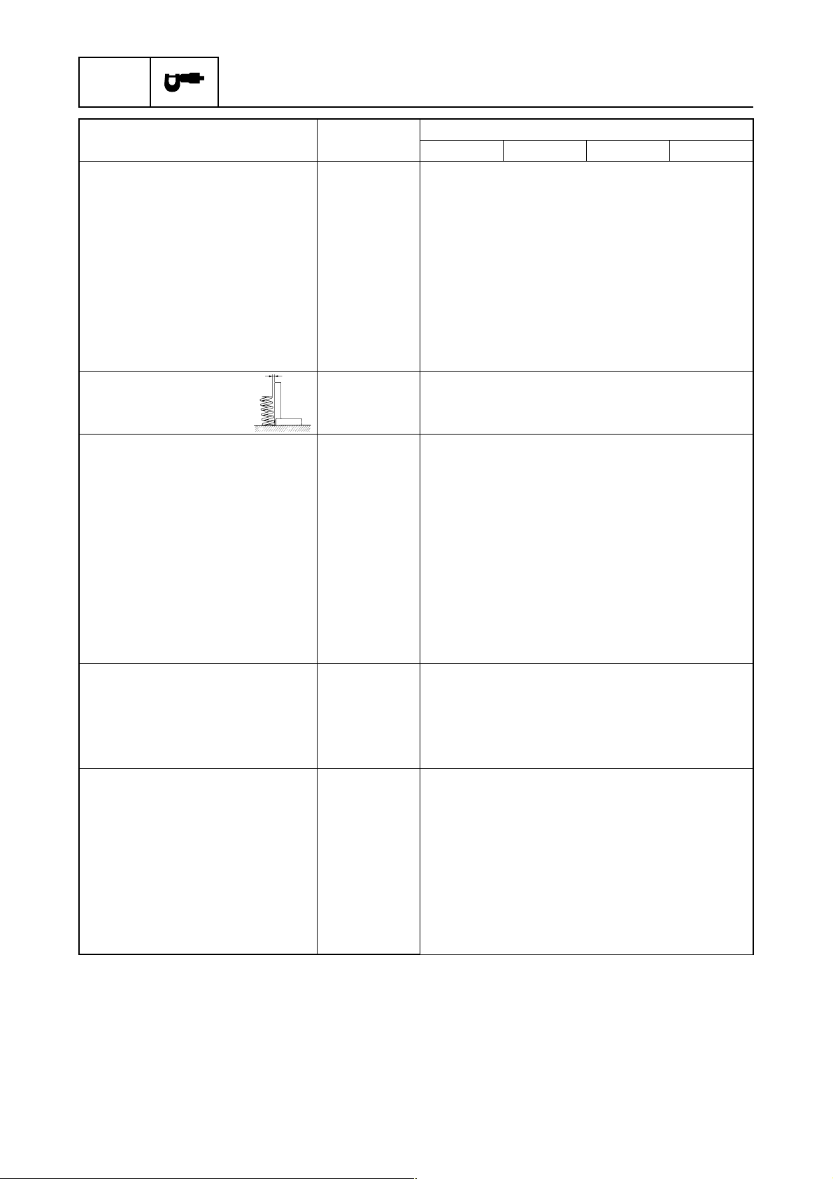
							GEN
INFO
General information
1-162Y3A11
How to use this manual1
Manual format
The format of this manual has been designed to make service procedures clear and easy to under-
stand. Use the information below as a guide for effective and quality service.
1
Parts are shown and detailed in an exploded diagram and are listed in the components list.
2
Tightening torque specifications are provided in the components list at the beginning of each
section and after a numbered step with tightening instructions.
3
Symbols are used to indicate important aspects of a procedure, such as the grade of lubricant
and lubrication point.
4
The components list consist of parts and part quantities, as well as bolt and screw dimensions.
5
Service points regarding removal, checking, and installation are shown in individual illustrations
to explain the relevant procedure.
6
This service manual has two types of special service tools. Use part numbers that start with “J-”,
“YB-”, “YM-”, “YS-”, “YU-”, “YW-”, or “YX-” for USA and Canada. Use parts numbers that start
with “90890-” for all other countries.
POWRPower unit
5-3562Y1A11
Cylinder head
62Y1A115-36
5
È
 Tightening sequence No. Part name Q’ty RemarksTightening torques
Stage N·mkgf·mft·lb
1 Cylinder head 1
2Oil pum p1
3 Cylinder head cover 1
4Bolt 7 M6 ×
 20 mm
5 Cylinder head cover
gasket1
Not reusable
6 Bolt 10 M9 ×
 95 mm 1st
2nd23
472.3
4.717
34
7 Spark plug 4 18 1.8 13
8Bolt 5 M6 ×
 25 mm 1st
2nd6
120.6
1.24.3
8.7
9 Dowel pin 2
10 Cylinder head gasket 1
Not reusable11 Grommet 4
12 Anode 4
13 Cover 4
14 Bolt 4
15 Cover 4
16 Bolt 4
17 O-ring 1
Not reusable18 O-ring 1Not reusable19 O-ring 1Not reusable20 Bolt 4 M6 ×
 40 mm
21 Housing 1
22 Drive shaft 1
23 Pin 1
24 Inner rotor 1
25 Outer rotor 1
26 Gasket 1
Not reusable27 Cover 1
28 Screw 2 M6 ×
 20 mm
Cylinder head
POWRPower unit
5-3162Y1A11
Removing the timing belt and
sprockets
1. Set the cylinder #1 piston position to
TDC of the compression stroke by align-
ing the “1” mark a
 on the driven sprocket
with the “” mark b
 on the cylinder
head.
CAUTION:Do not turn the drive sprocket counter-
clockwise, otherwise the valve system
may be damaged.
2. Remove the breather hose and loosen
the drive sprocket nut 1
.
NOTE:
Use a deep socket 2
 (M42) for this proce-
dure.
Do not turn the camshaft when loosening
the drive sprocket nut.3. Remove the tensioner 4
 and timing belt
5
 from the driven sprocket side.
4. Loosen the driven sprocket bolt 6
 and
remove the driven sprocket  .
ÈFor USA and Canada
ÉFor worldwide
NOTE:
Do not turn the camshaft when loosening the
driven sprocket bolt.
Crankshaft holder 3
: YB-06562
Crankshaft holder 18 3
: 90890-06562
Flywheel magnet holder: YB-06139
Flywheel holder: 90890-06522
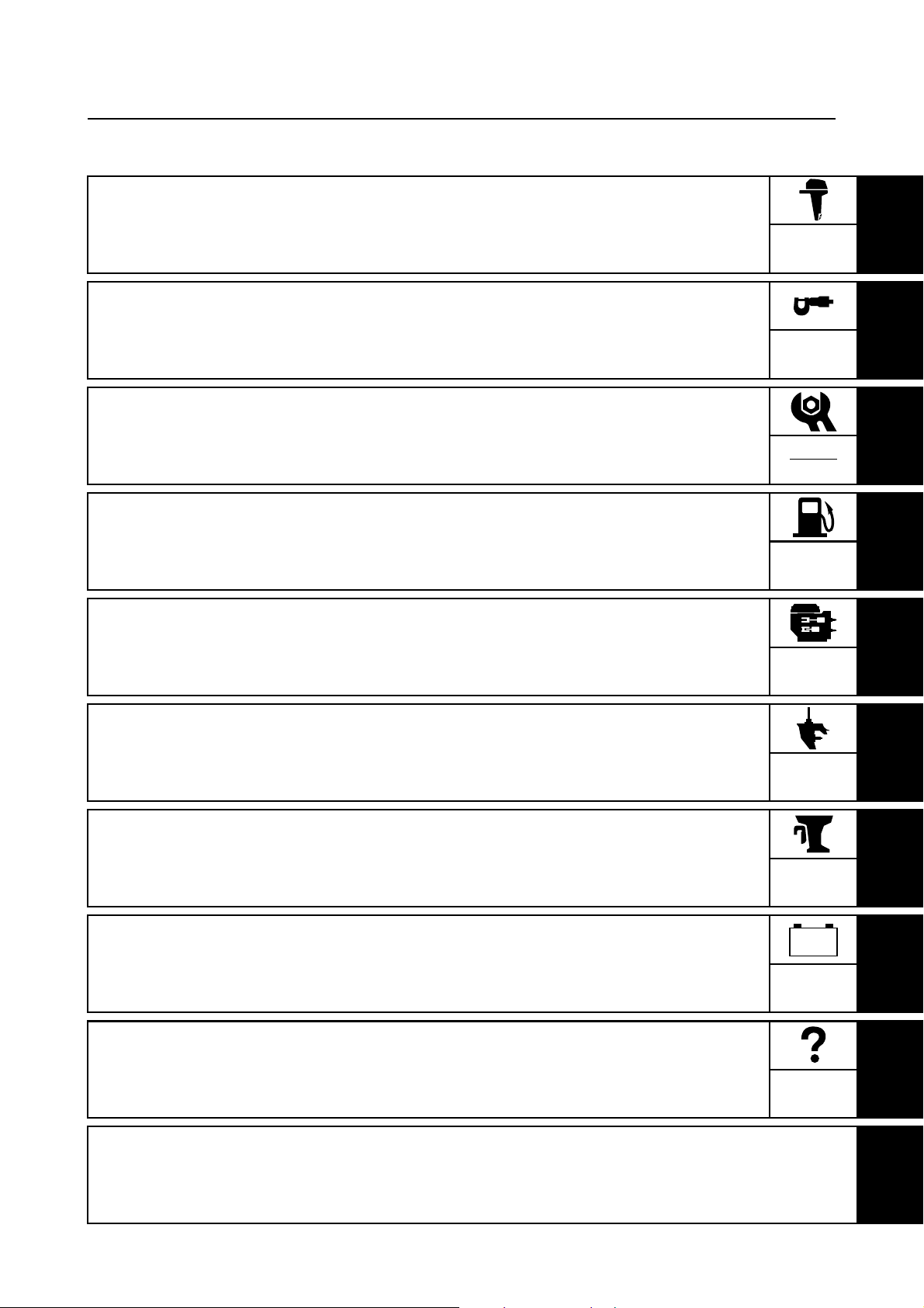
							62Y3A111-2
1
2
3
4
5
6
7
8
I
Symbols
The symbols below are designed to indicate the content of a chapter.
General information
Specifications
Periodic checks and adjustments
Fuel systemPower unit
Lower unit
Bracket unit
Electrical systems
Symbols 1
 to 5
 in an exploded diagram indicate the grade of lubricant and the lubrication point.
1Apply Yamaha 4-stroke motor oil
2Apply water resistant grease (Yamaha grease A, Yamaha marine grease)
3Apply molybdenum disulfide grease
4Apply anti-corrosion grease (Yamaha grease D)
5Apply low temperature resistant grease (Yamaha grease C)
Symbols 6
 to A
 in an exploded diagram indicate the type of sealant or locking agent and the appli-
cation point.
6Apply Gasket Maker®
7Apply Yamabond No. 4
8Apply LOCTITE
® No. 271 (Red LOCTITE)
9Apply LOCTITE® No. 242 (Blue LOCTITE)
0Apply LOCTITE® No. 572
AApply silicon sealant
GEN
INFO
SPEC
CHK

ADJ
FUEL
POWR
LOWR
BRKT
ELEC
–+
12345
67890A
E
AMDC
GM4
271
LT
242
LT
572
LTSS
How to use this manual
							GEN
INFO
General information
1-362Y3A11
Safety while working1
To prevent an accident or injury and to
ensure quality service, follow the safety pro-
cedures provided below.
Fire prevention
Gasoline is highly flammable.
Keep gasoline and all flammable products
away from heat, sparks, and open flames.
Ventilation
Gasoline vapor and exhaust gas are heavier
than air and extremely poisonous. If inhaled
in large quantities they may cause loss of
consciousness and death within a short time.
When test running an engine indoors (e.g., in
a water tank) be sure to do so where ade-
quate ventilation can be maintained.
Self-protection
Protect your eyes by wearing safety glasses
or safety goggles during all operations involv-
ing drilling and grinding, or when using an air
compressor.
Protect your hands and feet by wearing pro-
tective gloves and safety shoes when neces-
sary.
Parts, lubricants, and sealants
Use only genuine Yamaha parts, lubricants,
and sealants or those recommended by
Yamaha, when servicing or repairing the
outboard motor.
Under normal conditions, the lubricants men-
tioned in this manual should not harm or be
hazardous to your skin. However, you should
follow these precautions to minimize any risk
when working with lubricants.
1. Maintain good standards of personal and
industrial hygiene.
2. Change and wash clothing as soon as
possible if soiled with lubricants.
3. Avoid contact with skin. Do not, for
example, place a soiled rag in your
pocket.
4. Wash hands and any other part of the
body thoroughly with soap and hot water
after contact with a lubricant or lubricant
soiled clothing has been made.
5. To protect your skin, apply a protective
cream to your hands before working on
the outboard motor.
							62Y3A111-4
1
2
3
4
5
6
7
8
I
6. Keep a supply of clean, lint-free cloths for
wiping up spills, etc.
Good working practices
Special tools
Use the recommended special tools to pro-
tect parts from damage. Use the right tool in
the right manner—do not improvise.
Tightening torques
Follow the tightening torque specifications
provided throughout the manual. When tight-
ening nuts, bolts, and screws, tighten the
large sizes first, and tighten fasteners starting
in the center and moving outward.
Non-reusable parts
Always use new gaskets, seals, O-rings, cot-
ter pins, circlips, etc., when installing or
assembling parts.
Disassembly and assembly
1. Use compressed air to remove dust and
dirt during disassembly.
2. Apply engine oil to the contact surfaces
of moving parts before assembly.3. Install bearings with a manufacture iden-
tification mark in the direction indicated in
the installation procedure. In addition, be
sure to lubricate the bearings liberally.
4. Apply a thin coat of water-resistant
grease to the lip and out periphery of an
oil seal before installation.
5. Check that moving parts operate nor-
mally after assembly.
Safety while working
							GEN
INFO
General information
1-562Y3A11
Identification1
Applicable models
This manual covers the following models.
Serial number
The outboard motor serial number is
stamped on a label attached to the port
clamp bracket.
1Model name
2Approved model code
3Transom height
4Serial number
Applicable models
USA, Canada Worldwide
—F50AEHD
F50TH F50AEHT
—F50AED
F50TR F50AET
T50TR FT50BET
—FT50CEHD
—FT50CED
—FT50CET
Model nameApproved
model codeStarting
serial No.
USA, Canada
F50TH
62YL: 451812–
F50TR L: 421732–
T50TR 64J L: 406850–
Worldwide
F50AEHD
62YL: 350505–
F50AEHTL: 451812–
X: 750469–
F50AED L: 301090–
F50AETL: 421626–
X: 700700–
FT50BET
64JL: 406850–
FT50CEHD L: 650101–
FT50CED L: 550101–
FT50CET L: 450101–
All Yamaha manuals
Comments (0)
Related Manuals for Yamaha F50 Service Manual

F50F
FT50G
F60C
FT60D
290551
SERVICE MANUAL
6C1-28197-3G-11
NOTICE
This manual has been prepared by Yamaha primarily for use by Yamaha dealers and their trained
mechanics when performing maintenance procedures and repairs to Yamaha equipment. It has
been written to suit the needs of persons who have a basic understanding of the mechanical and
electrical concepts and procedures inherent in the work, for without such knowledge attempted
repairs or service to the equipment could render it unsafe or unfit for use.
Because Yamaha has a policy of continuously improving its products, models may differ in detail
from the descriptions and illustrations given in this publication. Use only the latest edition of this
manual. Authorized Yamaha dealers are notified periodically of modifications and significant
changes in specifications and procedures, and these are incorporated in successive editions of this
manual.
Important information
Particularly important information is distinguished in this manual by the following notations:
The Safety Alert Symbol means ATTENTION! BECOME ALERT! YOUR SAFETY IS
INVOLVED!
WARNING
Failure to follow WARNING instructions could result in severe injury or death to the machine
operator, a bystander, or a person inspecting or repairing the outboard motor.
CAUTION:
A CAUTION indicates special precautions that must be taken to avoid damage to the outboard motor.
NOTE:
A NOTE provides key information to make procedures easier or clearer.
1
F50F, FT50G, F60C, FT60D
SERVICE MANUAL
©2004 by Yamaha Motor Co., Ltd.
1st Edition, July 2004
All rights reserved.
Any reprinting or unauthorized use
without the written permission of
Yamaha Motor Co., Ltd.
is expressly prohibited.
Printed in the Netherlands
Contents
General information
Specifications
Periodic checks and adjustments
Fuel system
Power unit
GEN
INFO
SPEC
CHK
ADJ
FUEL
POWR
1
2
3
4
5
Lower unit
Bracket unit
Electrical systems
Troubleshooting
Index
LOWR
BRKT
–+
ELEC
TRBL
SHTG
6
7
8
9


GEN
INFO
General information
How to use this manual………………………………………………………………………1-1
Manual format………………………………………………………………………………..1-1
Symbols………………………………………………………………………………………..1-2
Safety while working…………………………………………………………………………..1-3
Fire prevention……………………………………………………………………………….1-3
Ventilation……………………………………………………………………………………..1-3
Self-protection ……………………………………………………………………………….1-3
Parts, lubricants, and sealants …………………………………………………………1-3
Good working practices …………………………………………………………………..1-4
Disassembly and assembly ……………………………………………………………..1-4
1
2
Identification………………………………………………………………………………………1-4
Applicable models ………………………………………………………………………….1-4
Serial number ………………………………………………………………………………..1-5
Outline of features ……………………………………………………………………………..1-6
Features and benefits…………………………………………………………………………1-7
Fuel system …………………………………………………………………………………..1-7
Solenoid valve ……………………………………………………………………………….1-8
Electronic control system…………………………………………………………………1-9
ECM (Electric Control Module) ……………………………………………………….1-10
Variable trolling RPM switch (optional)…………………………………………….1-11
Propeller selection……………………………………………………………………………1-12
Propeller size……………………………………………………………………………….1-12
Selection……………………………………………………………………………………..1-12
Predelivery checks …………………………………………………………………………..1-13
Checking the fuel system ………………………………………………………………1-13
Checking the engine oil level………………………………………………………….1-13
Checking the gear oil level …………………………………………………………….1-13
Checking the battery……………………………………………………………………..1-13
Checking the outboard motor mounting height………………………………….1-14
Checking the remote control cables ………………………………………………..1-14
Checking the steering system ………………………………………………………..1-14
Checking the gear shift and throttle operation…………………………………..1-15
Checking the power trim and tilt system…………………………………………..1-15
Checking the hydro tilt system………………………………………………………..1-15
Checking the engine start switch and engine stop lanyard switch ……….1-16
Checking the cooling water pilot hole ………………………………………………1-16
Test run ………………………………………………………………………………………1-17
Break-in ………………………………………………………………………………………1-17
After test run ………………………………………………………………………………..1-17
3
4
5
6
7
8
9
6C13G11
GEN
INFO
General information
How to use this manual
Manual format
The format of this manual has been designed to make service procedures clear and easy to understand. Use the information below as a guide for effective and quality service.
1
Parts are shown and detailed in an exploded diagram and are listed in the components list.
2
Tightening torque specifications are provided in the exploded diagrams and after a numbered
step with tightening instructions.
3
Symbols are used to indicate important aspects of a procedure, such as the grade of lubricant
and lubrication point.
4
The components list consists of part names and part quantities, as well as bolt and screw dimensions.
5
Service points regarding removal, checking, and installation are shown in individual illustrations
to explain the relevant procedure.
NOTE:
For troubleshooting procedures, see Chapter 9, “Troubleshooting.”
1
40 mm
10 45 mm
60 mm
3
LOWR
Lower unit
No. Part name Q’ty Remarks
1 Lower unit 1
2 Plastic tie 1
3Hose 1
4 Check screw 1
5 Gasket 2
6 Dowel pin 2
7 Bolt 4 M10
8 Drain screw 1
9Grommet 1
10 Bolt 1 M
11 Bolt 1 M8
12 Thrust washer 1
13 Propeller 1
14 Washer 1
15 Washer 1
16 Cotter pin 1
17 Propeller nut 1
18 Trim tab 1
6-5
Lower unit
Not reusable
Not reusable
Not reusable
4
2
62Y5A11
1
LOWR
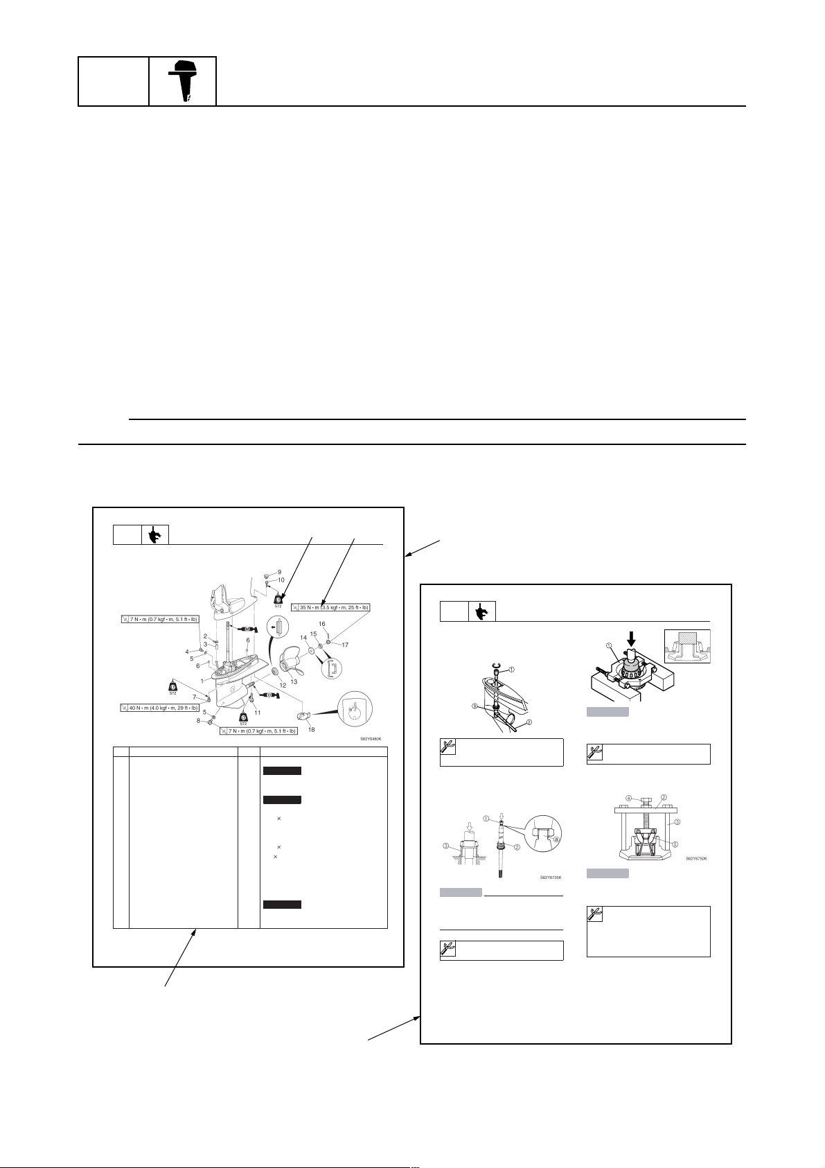
Removing the drive shaft
1. Remove the drive shaft assembly and
pinion, and then pull out the forward
gear.
Disassembling the drive shaft
1. Install the pinion nut 1, tighten it finger
tight, and then remove the drive shaft
bearing 2 using a press.
CAUTION:
• Do not press the drive shaft threads
directly.
• Do not reuse the bearing, always
replace it with a new one.
Disassembling the forward gear
1. Remove the taper roller bearing from the
forward gear using a press.
Lower unit
S62Y6850K
Drive shaft holder 4 1: 90890-06518
Pinion nut holder 2: 90890-06505
Socket adapter 2 3: 90890-06507
Bearing inner race attachment 3:
90890-06639
CAUTION:
Do not reuse the bearing, always replace
it with a new one.
Bearing separator 1: 90890-06534
2. Remove the needle bearing from the forward gear.
CAUTION:
Do not reuse the bearing, always replace
it with a new one.
a
Stopper guide plate 2: 90890-06501
Stopper guide stand 3:
90890-06538
Bearing puller 4: 90890-06535
Bearing puller claw 1 5:
90890-06536
S62Y6740K
1-1
5
6-19
62Y5A11
6C13G11
Symbols
The symbols below are designed to indicate the content of a chapter.
How to use this manual
General information
GEN
INFO
Specifications
SPEC
Periodic checks and adjustments
CHK
ADJ
Symbols 1 to 6 indicate specific data.
123456
Fuel system
FUEL
Power unit
POWR
Lower unit
LOWR
Bracket unit
BRKT
Electrical systems
ELEC
Troubleshooting
–+
TRBL
SHTG
1
2
3
4
Special tool
1
Specified oil or fluid
2
Specified engine speed
3
Specified tightening torque
4
Symbols 7 to C in an exploded diagram indicate the grade of lubricant and the lubrication point.
7890ABC
A M
E G
Apply Yamaha 4-stroke motor oil
7
Apply gear oil
8
Apply water resistant grease (Yamaha grease A)
9
Apply molybdenum disulfide grease
0
Symbols D to H in an exploded diagram indicate the type of sealant or locking agent and the application point.
DEFGH
GM
LT
271
Specified measurement
5
Specified electrical value
6
(resistance, voltage, electric current)
C I
Apply corrosion resistant grease
A
(Yamaha grease D)
Apply low temperature resistant grease
B
(Yamaha grease C)
Apply injector grease
C
LT
242
LT
572
SS
5
6
7
8
9
Apply Gasket Maker
D
Apply LOCTITE 271 (red)
E
Apply LOCTITE 242 (blue)
F
6C13G11
Apply LOCTITE 572
G
Apply silicon sealant
H
1-2
GEN
INFO
General information
Safety while working
To prevent an accident or injury and to
ensure quality service, follow the safety procedures provided below.
Fire prevention
Gasoline is highly flammable.
Keep gasoline and all flammable products
away from heat, sparks, and open flames.
Ventilation
Gasoline vapor and exhaust gas are heavier
than air and extremely poisonous. If inhaled
in large quantities they may cause loss of
consciousness and death within a short time.
When test running an engine indoors (e.g., in
a water tank) be sure to do so where adequate ventilation can be maintained.
1
Parts, lubricants, and sealants
Use only genuine Yamaha parts, lubricants,
and sealants or those recommended by
Yamaha, when servicing or repairing the outboard motor.
Under normal conditions, the lubricants mentioned in this manual should not harm or be
hazardous to your skin. However, you should
follow these precautions to minimize any risk
when working with lubricants.
Self-protection
Protect your eyes by wearing safety glasses
or safety goggles during all operations involving drilling and grinding, or when using an air
compressor.
Protect your hands and feet by wearing protective gloves and safety shoes when necessary.
1-3
1. Maintain good standards of personal and
industrial hygiene.
2. Change and wash clothing as soon as
possible if soiled with lubricants.
3. Avoid contact with skin. Do not, for
example, place a soiled rag in your
pocket.
4. Wash hands and any other part of the
body thoroughly with soap and hot water
after contact with a lubricant or lubricant
soiled clothing has been made.
5. To protect your skin, apply a protective
cream to your hands before working on
the outboard motor.
6C13G11
6. Keep a supply of clean, lint-free cloths for
wiping up spills, etc.
Good working practices
Special service tools
Use the recommended special service tools
to protect parts from damage. Use the right
tool in the right manner—do not improvise.
Tightening torques
Follow the tightening torque specifications
provided throughout the manual. When tightening nuts, bolts, and screws, tighten the
large sizes first, and tighten fasteners starting
in the center and moving outward.
Non-reusable parts
Always use new gaskets, seals, O-rings, cotter pins, circlips, etc., when installing or
assembling parts.
Safety while working / Identification
3. Install bearings with the manufacture
identification mark in the direction indicated in the installation procedure. In
addition, be sure to lubricate the bearings
liberally.
4. Apply a thin coat of water-resistant
grease to the lip and periphery of an oil
seal before installation.
5. Check that moving parts operate normally after assembly.
Identification
Applicable models
This manual covers the following models.
Applicable models
F50FED, F50FEHT, F50FET, FT50GET,
F60CEHT, F60CET, FT60DET
1
2
3
4
1
5
6
Disassembly and assembly
1. Use compressed air to remove dust and
dirt during disassembly.
2. Apply engine oil to the contact surfaces
of moving parts before assembly.
6C13G11
(*)
Hydro tilt model (For Europe)
(*)
Tiller handle model (For Oceania)
7
8
9
1-4
GEN
INFO
Serial number
The outboard motor serial number is
stamped on a label attached to the port
clamp bracket.
General information
S6C11010
Model name
1
Approved model code
2
Transom height
3
Serial number
4
Model name
Approved
model code
Starting
serial No.
F50FED
6C1 1000001–F50FEHT
F50FET
FT50GET 6C2 1000001–
F60CEHT
6C5 1000001–
F60CET
FT60DET 6C6 1000001–
(*)
Hydro tilt model (For Europe)
(*)
Tiller handle model (For Oceania)
1-5
6C13G11
Identification / Outline of features
Outline of features
New electronic fuel injected F50 and F60 outboard motors have a mainly redesigned fuel and intake
system based on the carbureted F60 outboard motor.
Power unit
• Single throttle body, single throttle valve
• Multi-point injection system, group injection
(#1/#4 and #2/#3)
• Group ignition system (#1/#4 and #2/#3)
• Large plastic intake manifold
• Compact plastic fuel rail
• Modularized intake system components
• Vapor separator with built-in pressure regulator
• Solenoid valve
• Fuel cooler
• Aluminum rocker arm
Electrical
• Compact electronic fuel injection system
• Self-diagnosis system and Yamaha Diagnostic
System
• Variable trolling RPM switch (optional for tiller
handle model)
• Throttle position sensor with learning function
(adjustment free)
• Compact charging system at low rpm
• Compact fuel injectors
• Fuel filter with water separator
1
1
2
3
4
5
6
Clamp bracket/upper case
• 2-piece upper case
• Upper portion case with oil sump
• Big capacity water wall structure around muffler
• Idle exhaust labyrinth structure
• Exclusive clamp bracket for permanent mount-
ing
Lower unit
• Same lower drive unit as carbureted F60 model
6C13G11
S6C11120
1-6
7
8
9
GEN
INFO
General information
Features and benefits
Fuel system
A pressure regulator is built into the vapor separator to obtain compact and simple fuel delivery
structure.
A plastic fuel rail is used to prevent it from corrosion and for light weight.
Fuel discharged from the pressure regulator returns to the vapor separator after cooling down
through the fuel cooler.
The fuel joint is used on the high pressure fuel hose to remove and/or install the intake unit easily.
Fuel filter (Optional) Fuel tank
Primer pump
Fuel filter with water separator
Fuel pump (Mechanical)
1
Fuel filter
Vapor separator
Electric fuel pump
Fuel cooler
Pressure regulator
injector
Fuel
#1
Fuel rail
Fuel
injector
#2 #3 #4
Fuel
injector
Fuel
injector
S6C11130
1-7
6C13G11
Features and benefits
Solenoid valve
Just after the engine is stopped, the cooling water supply is also stopped and the heat is conducted
to the vapor separator from the engine, causing birth of many fuel vapor gases.
The vapor gases are fed into the intake silencer to reburn them.
However, many vapor gases are sucked into the combustion chambers, causing a rich air and fuel
mixture, which is difficult to restart the engine.
So the solenoid valve has been used for better restarting engine while the engine is warm.
The solenoid valve stops the vapor gases not to return into the intake silencer.
1
2
3
Fuel tank
1
Fuel filter
2
Fuel pump
3
Fuel cooler
4
Return fuel hose
5
Pressure regulator
6
Solenoid valve
7
To throttle body
8
Fuel injector
9
Electric fuel pump
0
Fuel filter
A
Fuel
È
Vapor gas
É
4
5
6
7
8
6C13G11
9
1-8
GEN
INFO
Electronic control system
The electronic control system is built up by the sensors and the ECM (Electric control Module).
The ECM receives signals from the sensors and determines the air and fuel mixture (A/F), and ignition timing.
Under various condition, the ECM gives the best-suitable engine operation.
In addition, warning control, fail-safe control, a self-diagnosis function, etc., are equipped to
increase reliability.
General information
1
2
5
4
Sensor assembly
1
(intake air temperature and intake air
pressure)
ECM
2
Throttle position sensor
3
Oil pressure switch
4
6
3
Cooling water temperature sensor
5
Pulser coil
6
S6C11150
1-9
6C13G11
Features and benefits
ECM (Electric Control Module)
This engine is controlled by the ECM to obtain precision combustion under various operations, and
can realize high power output, low fuel consumption, and low emission.
The ECM controls the ignition timing, fuel injection timing, and the fuel injection volume, and
ensures that the optimum ignition timing and air and fuel ratio can be achieved in all operating conditions such as engine starting, normal operation, and quick acceleration.
The self-diagnosis function is incorporated into the ECM and can be easily found a malfunction
point by a personal computer with the optional software installed.
1
40
Pulser coil
16
Power source for sensors
36
Throttle position
sensor
17
Intake air pressure
sensor
46
Cooling water pressure sensor
31
Ground for sensors
38
Intake air temperature sensor
48
Cooling water temperature sensor
34
Shift position switch
Fuel injectors #1, #4
Fuel injectors #2, #3
Ignition coil #1, #4
Ignition coil #2, #3
Idle speed control (S1)
Idle speed control (S2)
Idle speed control (S3)
Idle speed control (S4)
Tachometer
Oil pressure warning
indicator
Overheat
warning
indicator
Check engine warning
indicator
Buzzer/DES switch
Solenoid valve
Fuel pump relay
3
4
18
1
23
6
20
21
7
26
8
25
9
DES switch
11
24
OUTPUTINPUT
Main relay
Relay
2
3
4
T
BZ
P
5
6
7
6C13G11
Flywheel
magnet
Rectifier Regulator
– +
Battery
27
Engine stop lanyard switch
10
Oil pressure switch
28
Variable trolling RPM switch (UP)
29
Variable trolling RPM switch
(DOWN)
14
Ground for ECM
5
Ground
15
Battery (+)
Engine start switch
Main relay
Diagnosis
45
13
Power for diagnosis lamp
Self-diagnosis
8
9
S6C11160
1-10
GEN
INFO
Variable trolling RPM switch (optional)
This device is an optional equipment for tiller handle model.
The idling and/or trolling rpm can be controlled in the range of 620 through 900 r/min with 50 r/min
interval.
Especially for 620 through 700 r/min, the engine rpm is controlled with 40 r/min interval.
Pushing and holding the switch changes rpm continuously at 50 r/min interval.
If engine rpm reaches to the ends of specified range, the rpm is no longer changed.
CAUTION:
Do not modify the variable trolling RPM switch.
Modification such as wire extension, disassembly, etc., can malfunction for the system and/
or damage the electrical components.
NOTE:
Variable trolling RPM switch kit P/N: 6C5-W8186-00
General information
Variable trolling RPM switch (optional)
1
1
S6C11170
1-11
6C13G11
Features and benefits / Propeller selection
Propeller selection
The performance of a boat and outboard
motor will be critically affected by the size
and type of propeller you choose. Propellers
greatly affect boat speed, acceleration,
engine life, fuel economy, and even boating
and steering capabilities. An incorrect choice
could adversely affect performance and
could also seriously damage the engine.
Use the following information as a guide for
selecting a propeller that meets the operating
conditions of the boat and the outboard
motor.
Propeller size
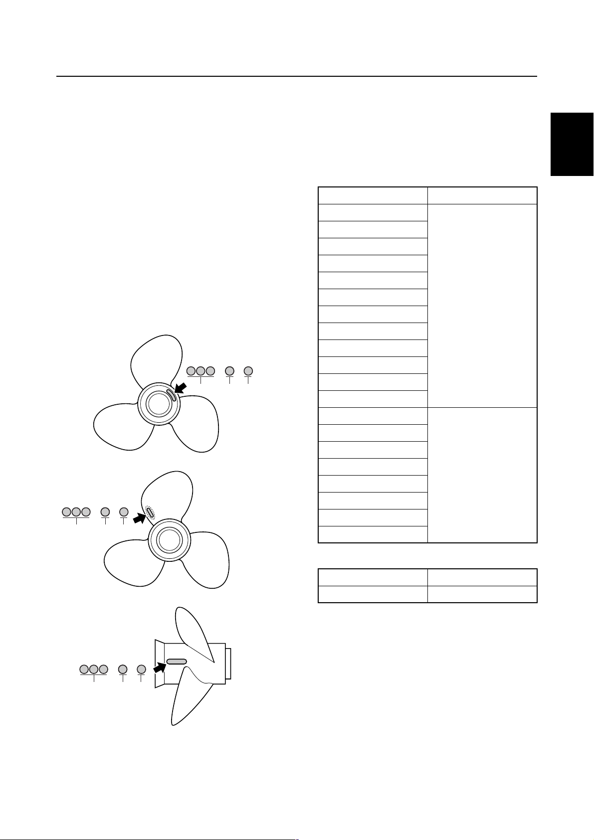
The size of the propeller is indicated on a
propeller blade, on the propeller boss end.
× —
a
bc
1
Selection
When the engine speed is at the full throttle
operating range (5,000–6,000 r/min), the
ideal propeller for the boat is one that provides maximum performance in relation to
boat speed and fuel consumption.
F50, F60
Propeller size (in) Material
10 × 15 — G
10 1/4 × 14 — G
10 3/8 × 13 — G
10 5/8 × 12 — G
10 3/4 × 16 — G
10 3/4 × 17 — G
Aluminum
11 × 15 — G
11 1/8 × 13 — G
11 1/4 × 14 — G
11 3/8 × 12 — G
11 5/8 × 11 — G
12 1/4 × 9 — G
1
2
3
4
× —
a
bc
× —
a
bc
S69W1030
S69W1040
10 1/4 × 14 — G
10 1/4 × 15 — G
10 1/4 × 16 — G
10 5/8 × 13 — G
Stainless
11 1/4 × 14 — G
11 1/2 × 13 — G
11 3/4 × 12 — G
12 × 11 — G
FT50, FT60
Propeller size (in) Material
14 × 11 — K Aluminum
5
6
7
8
9
Propeller diameter (in inches)
a
Propeller pitch (in inches)
b
Propeller type (propeller mark)
c
6C13G11
S69W1050
1-12
GEN
INFO
General information
Predelivery checks
To make the delivery process smooth and
efficient, the predelivery checks should be
completed as explained below.
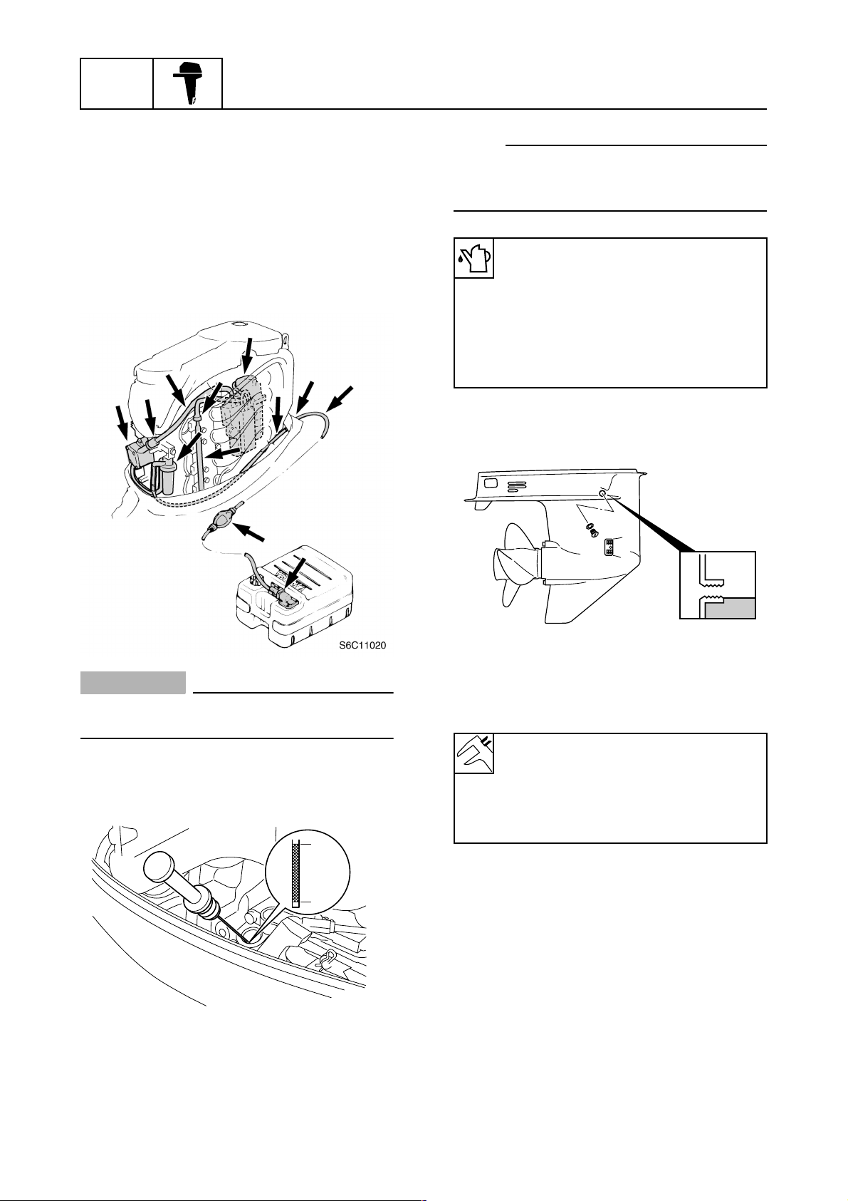
Checking the fuel system
1. Check that the fuel hoses are securely
connected and that the fuel tank is full
with fuel.
1
NOTE:
If the engine oil is below the minimum level
mark b, add sufficient oil until the level is
between a and b.
Recommended engine oil:
4-stroke motor oil
API: SE, SF, SG, SH, or SJ
SAE: 10W-30 or 10W-40
Engine oil quantity:
Without oil filter replacement:
2.5 L (2.64 US qt, 2.20 Imp qt)
Checking the gear oil level
1. Check the gear oil level.
CAUTION:
This is a 4-stroke engine. Never use premixed fuel.
Checking the engine oil level
1. Check the engine oil level.
a
b
S6C11030
S60V1290
Checking the battery
1. Check the capacity, electrolyte level, and
specified gravity of the battery.
Recommended battery capacity:
CCA/EN: 430 A
20HR/IEC: 70 Ah
Electrolyte specified gravity:
1.280 at 20 °C (68 °F)
2. Check that the positive and negative battery leads are securely connected.
1-13
6C13G11
Predelivery checks
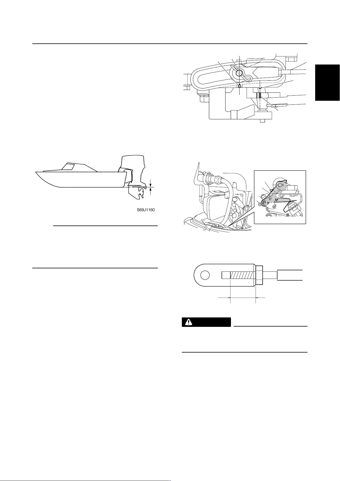
Checking the outboard motor
mounting height
1. Check that the anti-cavitation plate is
aligned with the bottom of the boat. If the
mounting height is too high, cavitation
will occur and propulsion will be reduced.
Also, the engine speed will increase
abnormally and cause the engine to
overheat. If the mounting height is too
low, water resistance will increase and
reduce engine efficiency.
a
b
d
c
S6C11080
4. Check that the edge of a shift rod e is
aligned with the alignment mark f on
the bottom cowling.
f
e
1
2
3
4
NOTE:
The optimum mounting height is affected by
the combination of the boat and the outboard
motor. To determine the optimum mounting
height, test run the outboard motor at different heights.
2. Check that the clamp brackets are
secured with the clamp bolts.
Checking the remote control cables
1. Set the remote control lever or shift lever
to the neutral position and fully close the
throttle lever or throttle grip.
2. Check that the set pin a is aligned with
the alignment mark b.
3. Check that the alignment mark c is
aligned with the mark d.
S6C11090
g
WARNING
The shift/throttle cable joint must be
screwed in a minimum of 8.0 mm (0.31 in)
.
g
Checking the steering system
1. Check the steering friction for proper
adjustment.
S6C11110
5
6
7
8
6C13G11
9
1-14
GEN
INFO
General information
2. Check that the steering operates
smoothly.
È
É
Tiller handle model
È
Remote control model
É
3. Check that there is no interference with
wires or hoses when the outboard motor
is steered.
È
É
N
F
R
a
a
S69J1210
Tiller handle model
È
Remote control model
É
Checking the power trim and tilt
system
1. Check that the outboard motor tilts up
and down smoothly when operating the
power trim and tilt unit.
Checking the gear shift and throttle
operation
1. Check that the gear shift operates
smoothly when the remote control lever
or shift lever is shifted from neutral to forward or reverse.
2. Check that the throttle operates smoothly
when the throttle grip (tiller handle
model) is turned from the fully closed
position to the fully open position a.
Check that the throttle operates smoothly
when the remote control lever (remote
control model) is shifted from forward or
reverse to the fully open position a.
2. Check that there is no abnormal noise
produced when the outboard motor is
tilted up or down.
3. Check that there is no interference with
wires or hoses when the tilted-up outboard motor is steered.
4. Check that the trim meter points down
when the outboard motor is tilted all the
way down.
Checking the hydro tilt system
1. Check that the outboard motor tilts up
and down smoothly.
2. Fully tilt the outboard motor up, and then
lock the tilt stop lever 1 to check the lock
mechanism of the hydro tilt. Replace the
hydro tilt unit if necessary.
1-15
6C13G11
Predelivery checks
1
S6C11100
Checking the engine start switch and
engine stop lanyard switch
1. Check that the engine starts when the
engine start switch is turned to START.
2. Check that the engine turns off when the
engine start switch is turned to OFF.
È
È
É
1
2
3
4
É
Tiller handle model
È
Remote control model
É
3. Check that the engine turns off when the
engine stop lanyard switch is pushed or
engine stop lanyard is pulled from the
engine stop lanyard switch.
OFF
ON
START
S60V1070
Tiller handle model
È
Remote control model
É
Checking the cooling water pilot
hole
1. Check that cooling water is discharged
from the cooling water pilot hole.
5
6
7
8
9
6C13G11
1-16

GEN
INFO
General information
Test run
1. Start the engine, and then check that the
gear shift operates smoothly.
2. Check the engine idle speed after the
engine has been warmed up.
3. Operate at trolling speed.
4. Run the outboard motor for 1 hour at
2,000 r/min or at half throttle, then for
another hour at 3,000 r/min or at 3/4
throttle.
5. Check that the outboard motor does not
tilt up when shifting into reverse and that
water does not flow in over the transom.
NOTE:
The test run is part of the break-in operation.
After test run
1. Check for water in the gear oil.
2. Check for fuel leakage in the cowling.
3. Flush the cooling water passage with
fresh water using the flushing kit and with
the engine running at idle.
Break-in
During the test run, perform the break-in
operation in the following three stages.
1. One hour a at 2,000 r/min or at approximately half throttle
2. One hour b at 3,000 r/min or 3/4 throttle
and 1 minute out of every 10 at full throttle
3. Eight hours c at any speed, however,
avoid running at full speed for more than
5 minutes
È
ab
0
1
210
c
Hour
È
1-17
S69J1240
6C13G11

SPEC
Specifications
General specifications………………………………………………………………………..2-1
Maintenance specification ………………………………………………………………….2-5
Power unit……………………………………………………………………………………..2-5
Lower unit ……………………………………………………………………………………..2-8
Electrical ……………………………………………………………………………………….2-9
Power unit……………………………………………………………………………………2-11
Lower unit ……………………………………………………………………………………2-14
Electrical ……………………………………………………………………………………..2-15
Dimensions………………………………………………………………………………….2-17
Tightening torques……………………………………………………………………………2-21
Specified torques………………………………………………………………………….2-21
General torques……………………………………………………………………………2-24
1
2
3
4
5
6
7
8
9
6C13G11
SPEC
Specifications
General specifications
1,339
(52.7)
114.0
(251)
Tiller
Model
706 (27.8)
110.0
(243)
Remote control
Item Unit
F50FED F50FEHT F50FET FT50GET
Dimension
Overall length mm (in) 706
(27.8)
Overall width mm (in) 384 (15.1)
Overall height
(L) mm (in) 1,415 (55.7) 1,455
(*1)
(X)
mm (in) — 1,569
Boat transom height
(L) mm (in) 508 (20.0)
(*1)
(X)
mm (in) — 635
Weight
(with aluminium propeller)
(L) kg (lb) 107.0
(236)
(*1)
(X)
kg (lb) — 119.0
Performance
Maximum output kW (hp) 36.8 (50.0) at 5,500 r/min
Full throttle operating range r/min 5,000–6,000
Maximum fuel consumption L (US gal,
18.5 (4.89, 4.07) at 6,000 r/min
lmp gal)/hr
Engine idle speed r/min 700–800
Power unit
Type In-line, 4-stroke, SOHC, 8 valves
Cylinder quantity 4
Total displacement cm
3
(cu. in) 996 (60.8)
Bore × stroke mm (in) 65.0 × 75.0 (2.56 × 2.95)
Compression ratio 9.50
Control system Remote
control
handle
Starting system Electric
Fuel system Fuel injection
Ignition system TCI
Advance system Micro computer
Maximum generator output V, A 12, 16
Spark plug DPR6EB-9 (NGK)
Cooling system Water
Exhaust system Propeller boss
Lubrication system Wet sump
(*1)
For Oceania
2
(57.3)
(61.8)
(25.0)
115.0
(254)
(262)
2-1
6C13G11
General specifications
Item Unit
Fuel and oil
Fuel type Regular unleaded gasoline
Fuel minimum rating RON
Engine oil 4-stroke motor oil
Engine oil grade
Engine oil quantity
(without oil filter replacement) L (US qt,
(with oil filter replacement) L (US qt,
Gear oil type Hypoid gear oil
Gear oil grade
Gear oil quantity cm
Bracket unit
Trim angle
(at 12° boat transom)
Tilt-up angle Degree 67 69
Steering angle Degree 40 + 40
Drive unit
Gear shift positions F-N-R
Gear ratio 1.85 (13/24) 2.31
Reduction gear type Spiral bevel gear
Clutch type Dog clutch
Propeller shaft type Spline
Propeller direction (rear view) Clockwise
Propeller identification mark G K
Electrical
Battery minimum capacity
CCA/EN A 430
20HR/IEC Ah 70
(*1)
RON: Research Octane Number
PON: Pump Octane Number = (RON + Motor Octane Number)/2
(*2)
Meeting both API and SAE requirements
(*3)
CCA: Cold Cranking Ampere
EN: European Norm (European standard)
IEC: International Electrotechnical Commission
(*2)
API GL-4
(*3)
(*1)
PON
API
SAE
lmp qt)
lmp qt)
SAE 90
3
(US oz,
lmp oz)
Degree –4 to 20
F50FED F50FEHT F50FET FT50GET
SE, SF, SG, SH, or SJ
10W-30 or 10W-40
430 (14.5, 15.2) 670
Model
90
86
2.5 (2.64, 2.20)
2.7 (2.85, 2.38)
(22.7,
23.6)
(13/30)
1
2
3
4
5
6
7
8
9
6C13G11
2-2
SPEC
Specifications
Item Unit
F60CEHT F60CET FT60DET
Model
Dimension
Overall length mm (in) 1,339 (52.7) 706 (27.8)
Overall width mm (in) 384 (15.1)
Overall height
(L) mm (in) 1,415 (55.7) 1,455 (57.3)
(*1)
(X)
mm (in) — 1,569 (61.8)
Boat transom height
(L) mm (in) 508 (20.0)
(*1)
(X)
mm (in) — 635 (25.0)
Weight
(with aluminium propeller)
(L) kg (lb) 114.0 (251) 110.0 (243) 115.0 (254)
(*1)
(X)
kg (lb) — 119.0 (262)
Performance
Maximum output kW (hp) 44.1 (60.0) at 5,500 r/min
Full throttle operating range r/min 5,000–6,000
Maximum fuel consumption L (US gal,
20.0 (5.28, 4.40) at 6,000 r/min
lmp gal)/hr
Engine idle speed r/min 700–800
Power unit
Type In-line, 4-stroke, SOHC, 8 valves
Cylinder quantity 4
Total displacement cm
3
(cu. in) 996 (60.8)
Bore × stroke mm (in) 65.0 × 75.0 (2.56 × 2.95)
Compression ratio 9.50
Control system Tiller handle Remote control
Starting system Electric
Fuel system Fuel injection
Ignition system TCI
Advance system Micro computer
Maximum generator output V, A 12, 16
Spark plug DPR6EB-9 (NGK)
Cooling system Water
Exhaust system Propeller boss
Lubrication system Wet sump
(*1)
For Oceania
2-3
6C13G11
General specifications
Item Unit
Fuel and oil
Fuel type Regular unleaded gasoline
Fuel minimum rating RON
Engine oil 4-stroke motor oil
Engine oil grade
Engine oil quantity
(without oil filter replacement) L (US qt,
(with oil filter replacement) L (US qt,
Gear oil type Hypoid gear oil
Gear oil grade
Gear oil quantity cm
Bracket unit
Trim angle
(at 12° boat transom)
Tilt-up angle Degree 69
Steering angle Degree 40 + 40
Drive unit
Gear shift positions F-N-R
Gear ratio 1.85 (13/24) 2.31 (13/30)
Reduction gear type Spiral bevel gear
Clutch type Dog clutch
Propeller shaft type Spline
Propeller direction (rear view) Clockwise
Propeller identification mark G K
Electrical
Battery minimum capacity
CCA/EN A 430
20HR/IEC Ah 70
(*1)
RON: Research Octane Number
PON: Pump Octane Number = (RON + Motor Octane Number)/2
(*2)
Meeting both API and SAE requirements
(*3)
CCA: Cold Cranking Ampere
EN: European Norm (European standard)
IEC: International Electrotechnical Commission
(*2)
API GL-4
(*3)
(*1)
PON
API
SAE
lmp qt)
lmp qt)
SAE 90
3
(US oz,
lmp oz)
Degree –4 to 20
F60CEHT F60CET FT60DET
SE, SF, SG, SH, or SJ
10W-30 or 10W-40
430 (14.5, 15.2) 670
Model
90
86
2.5 (2.64, 2.20)
2.7 (2.85, 2.38)
(22.7, 23.6)
1
2
3
4
5
6
7
8
9
6C13G11
2-4
SPEC
Specifications
Maintenance specification
Power unit
Item Unit
F50FED F50FEHT F50FET FT50GET
Power unit
Minimum compression
pressure
Oil pressure
(*1)
(*2)
kPa
kPa
(kgf/cm2, psi)
(kgf/cm
2
, psi)
125 (1.25, 18.1) at engine idle speed
Cylinder head
Warpage limit mm (in) 0.10 (0.0039)
(lines indicate straightedge
position)
Journal inside diameter mm (in) 37.000–37.025 (1.4567–1.4577)
Cylinders
Bore size mm (in) 65.000–65.015 (2.5591–2.5596)
Taper limit mm (in) 0.08 (0.0032)
Out-of-round limit mm (in) 0.05 (0.0020)
Pistons
Piston diameter (D) mm (in) 64.950–64.965 (2.5571–2.5577)
Measuring point (H) mm (in) 5.0 (0.20)
Piston clearance mm (in) 0.035–0.065 (0.0014–0.0026)
Piston pin boss bore mm (in) 15.974–15.985 (0.6289–0.6293)
Oversize piston diameter
1st mm (in) 65.200–65.215 (2.5669–2.5675)
2nd mm (in) 65.450–65.465 (2.5768–2.5774)
Piston pins
Outside diameter mm (in) 15.965–15.970 (0.6285–0.6287)
Piston rings
Top ring
Dimension B mm (in) 1.17–1.19 (0.0461–0.0469)
Dimension T mm (in) 2.30–2.50 (0.0905–0.0984)
End gap mm (in) 0.15–0.30 (0.0059–0.0118)
Side clearance mm (in) 0.02–0.06 (0.0008–0.0024)
(*1)
Measure conditions:
Ambient temperature 20 °C (68 °F), wide open throttle, with spark plugs removed from all cylinders.
The figures are for reference only.
(*2)
The figures are for reference only.
Model
960 (9.6, 139.2)
2
2-5
6C13G11
Maintenance specification
Item Unit
2nd piston ring
Dimension B mm (in) 1.47–1.49 (0.0579–0.0587)
Dimension T mm (in) 2.60–2.80 (0.1024–0.1102)
End gap mm (in) 0.30–0.50 (0.0118–0.0197)
Side clearance mm (in) 0.02–0.06 (0.0008–0.0024)
Oil ring
Dimension B mm (in) 2.36–2.48 (0.0929–0.0976)
Dimension T
End gap mm (in) 0.20–0.70 (0.0079–0.0276)
Side clearance mm (in) 0.04–0.18 (0.0016–0.0071)
Camshaft
Intake (A) mm (in) 30.888–30.988 (1.2161–1.2200)
Exhaust (A) mm (in) 30.824–30.924 (1.2135–1.2175)
Intake and
exhaust (B)
Camshaft journal diameter
#1
Camshaft journal diameter
#2, #3, #4
Camshaft journal oil clearance mm (in) 0.045–0.090 (0.0018–0.0035)
Camshaft runout limit mm (in) 0.03 (0.0012)
Rocker arm shaft
Rocker arm shaft outside
diameter
Rocker arms
Rocker arm inside diameter mm (in) 16.000–16.018 (0.6299–0.6306)
Valves
Valve clearance (cold)
Intake mm (in) 0.20
Exhaust mm (in) 0.30
Head diameter (A)
Intake mm (in) 31.90–32.10 (1.256–1.264)
Exhaust mm (in) 26.60–26.80 (1.047–1.055)
Face width (B)
Intake mm (in) 1.98–2.40 (0.078–0.094)
Exhaust mm (in) 2.16–2.79 (0.085–0.110)
Seat contact width (C)
Intake and exhaust mm (in) 1.3–1.5 (0.051–0.059)
Margin thickness (D)
Intake mm (in) 0.8–1.2 (0.031–0.047)
Exhaust mm (in) 1.0–1.4 (0.039–0.055)
(*1)
mm (in) 2.75 (0.1083)
mm (in) 25.950–26.050 (1.0216–1.0256)
mm (in) 36.925–36.945 (1.4537–1.4545)
mm (in) 36.935–36.955 (1.4541–1.4549)
mm (in) 15.971–15.991 (0.6288–0.6296)
F50FED F50FEHT F50FET FT50GET
Model
±
0.05 (0.008
±
0.05 (0.012
±
±
0.002)
0.002)
1
2
3
4
5
6
7
8
9
(*1)
The figures are for reference only.
6C13G11
2-6
SPEC
Specifications
Item Unit
Stem diameter
Intake mm (in) 5.475–5.490 (0.2156–0.2161)
Exhaust mm (in) 5.460–5.475 (0.2150–0.2156)
Guide inside diameter
Intake and exhaust mm (in) 5.500–5.512 (0.2165–0.2170)
Stem-to-guide clearance
Intake and exhaust mm (in) 0.025–0.052 (0.0010–0.0020)
Stem runout limit
Intake mm (in) 0.05 (0.0020)
Exhaust mm (in) 0.03 (0.0012)
Valve springs
Free length mm (in) 39.85 (1.5689)
Tilt limit mm (in) 1.7 (0.07)
Connecting rods
Small end inside diameter mm (in) 15.985–15.998 (0.6293–0.6298)
Big end inside diameter mm (in) 36.000–36.024 (1.4173–1.4183)
Connecting rod big end side
clearance
Crankpin oil clearance mm (in) 0.016–0.040 (0.0006–0.0016)
Big end bearing thickness
Yellow mm (in) 1.500–1.504 (0.0591–0.0592)
Red mm (in) 1.496–1.500 (0.0589–0.0591)
Pink mm (in) 1.492–1.496 (0.0587–0.0589)
Green mm (in) 1.488–1.492 (0.0586–0.0587)
Crankshaft
Crankshaft journal diameter mm (in) 42.984–43.000 (1.6923–1.6929)
Crankpin diameter mm (in) 32.984–33.000 (1.2986–1.2992)
Crankpin width mm (in) 21.000–21.070 (0.8268–0.8295)
Runout limit mm (in) 0.03 (0.0012)
Crankcase
Crankshaft main journal oil
clearance
Crankcase main journal
bearing thickness
Yellow mm (in) 1.502–1.506 (0.0591–0.0592)
Red mm (in) 1.498–1.502 (0.0590–0.0591)
Pink mm (in) 1.494–1.498 (0.0588–0.0590)
Green mm (in) 1.490–1.494 (0.0587–0.0588)
mm (in) 0.05–0.22 (0.0020–0.0087)
mm (in) 0.012–0.036 (0.0005–0.0014)
F50FED F50FEHT F50FET FT50GET
Model
2-7
6C13G11
Loading…
View the manual for the Yamaha F50 here, for free. This user manual comes under the category outboard motors and has been rated by 15 people with an average of a 8.2. This manual is available in the following languages: English. Do you have a question about the Yamaha F50?
Ask your question here
Yamaha F50 specifications
Below you will find the product specifications and the manual specifications of the Yamaha F50.
The Yamaha F50 is an outboard motor that is commonly used for boating. With a displacement of 996cc, it offers a reliable and efficient performance. The motor has a maximum output of 50 horsepower and a range of operating speeds. Its compact and lightweight design make it easy to handle and transport. The F50 is equipped with electronic fuel injection, which optimizes fuel efficiency and provides smooth acceleration. It also has options for propeller pitch and trolling speed, making it versatile for a variety of boating activities. The motor has a corrosion-resistant construction, with a multi-layer coating on all exposed engine surfaces. Additionally, it features an antitheft system that enhances security and protection. The F50 is designed for easy maintenance, with an oil change system that simplifies the process. Its noise reduction technology offers a quiet and comfortable ride while minimizing the impact on the environment. Overall, the Yamaha F50 is a reliable and efficient choice for boaters looking for a quality outboard motor.
General
Frequently asked questions
Can’t find the answer to your question in the manual? You may find the answer to your question in the FAQs about the Yamaha F50 below.
What is the difference between E10 and E5 petrol?
E10 petrol consists of up to ten per cent ethanol while E5 petrol will contain less than five per cent ethanol. As a result, the percentage of E10 petrol is lower than that of E5 petrol, making it less bad for the environment.
Is the manual of the Yamaha F50 available in English?
Yes, the manual of the Yamaha F50 is available in English .
Is your question not listed? Ask your question here
Yamaha F50 (2021)
Read this manual carefully before operating this
outboard motor.
OWNER’S MANUAL
F40H
F40G
F50H
FT50J
F60F
FT60G
F70A
6C1-28199-7K-E0
6C1-9-7K-1E0.book 1 ページ 2020年11月26日 木曜日 午後5時31分
View the manual for the Yamaha F50 (2021) here, for free. This manual comes under the category outboard motors and has been rated by 1 people with an average of a 7.5.
This manual is available in the following languages: English. Do you have a question about the Yamaha F50 (2021) or do you need help?
Ask your question here
Product Images (1)
Yamaha F50 (2021) specifications
Below you will find the product specifications and the manual specifications of the Yamaha F50 (2021).
The Yamaha F50 is an outboard motor released in 2021. It is designed to provide reliable and efficient performance for boats and marine vessels. The motor offers a range of features and specifications that are tailored to meet the needs of boating enthusiasts.
The Yamaha F50 is powered by a four-stroke, 50 horsepower engine, which ensures smooth and quiet operation. This motor is also equipped with Yamaha’s Variable Trolling RPM Switch (VTS) technology, allowing for precise and easy control of trolling speeds.
The F50 features a lightweight and compact design, making it suitable for a variety of boat sizes and types. It is also equipped with Yamaha’s exclusive PrimeStart system, enabling quick and easy starting in any weather conditions.
In terms of fuel efficiency, the Yamaha F50 utilizes a fuel injection system, which optimizes fuel delivery and reduces consumption. This ensures longer trips and fewer fuel stops, enhancing the overall boating experience.
The motor is designed with durability in mind, featuring a high-quality construction and corrosion-resistant materials. It is also equipped with Yamaha’s patented Shift Dampener System (SDS), which reduces noise and vibration for a smoother ride.
Overall, the Yamaha F50 is a reliable and efficient outboard motor that provides boaters with the power and performance they need on the water. Its advanced features and durable construction make it a popular choice among marine enthusiasts.
General
Frequently Asked Questions
Can’t find the answer to your question in the manual? You may find the answer to your question in the FAQs about the Yamaha F50 (2021) below.
Why does my outboard motor Yamaha F50 (2021) not start?
Ensure that the fuel tank is adequately filled with the correct fuel mixture, the ignition switch is turned on, and that the choke is properly set. Additionally, check the spark plug for any signs of damage or fouling.
How can I troubleshoot if my outboard motor Yamaha F50 (2021) overheats?
Verify that the cooling water inlet is not blocked or clogged, and that there are no obstructions in the cooling water passages. Avoid running the engine at high speeds without proper cooling, and ensure the cooling system is functioning optimally.
Why is my outboard motor Yamaha F50 (2021) vibrating excessively?
Ensure that the propeller is securely fastened and balanced. Check for any damage or deformation to the propeller, as it could be causing the vibration. Additionally, inspect the engine mounting and tighten any loose bolts or nuts.
How can I improve the fuel efficiency of my outboard motor Yamaha F50 (2021)?
Maintain proper engine trim and avoid operating the motor at unnecessarily high speeds. Regularly clean the anti-ventilation plate and propeller to reduce drag. Additionally, ensure that the fuel system is free from leaks and maintain a clean fuel filter.
What should I do if my outboard motor Yamaha F50 (2021) is emitting excessive smoke?
Verify that the fuel being used is of the correct type and quality. If the fuel is old or contaminated, drain and replace it with fresh fuel. Ensure that the oil injection system is operating correctly, and inspect the spark plugs for any signs of oil fouling.
What is the difference between E10 and E5 petrol?
E10 petrol consists of up to ten per cent ethanol while E5 petrol will contain less than five per cent ethanol. As a result, the percentage of E10 petrol is lower than that of E5 petrol, making it less bad for the environment.
Is the manual of the Yamaha F50 (2021) available in English?
Yes, the manual of the Yamaha F50 (2021) is available in English .
Is your question not listed? Ask your question here
-
Страница 1
Read this manual carefully before operating this outboard motor. O WNER’S MANU AL F50 T50 F60 T60 F70 LIT-18626-09-90 6C1-28199-3B-E0 6C1-9-3B-1E0.book 1 ページ 2012年 11月19日 月曜日 午前10時35分[…]
-
Страница 2
EMU25063 ZMU07696 Les gaz d’échappement du moteur de ce pr oduit contiennent des substances chimiques connues dans l’État de Californie pour pr o v oquer le cancer , des anomalies congénitales et des troubles de la reproduction. Read this manual carefully before oper ating this outboard motor. Keep this manual onboard in a waterproof bag whe[…]
-
Страница 3
Important manual information EMU44140 To the owner Thank you for selecting a Yamaha outboard motor. This Owner’s Manual contains infor- mation needed for proper operation, mainte- nance and care. A thorough understanding of these simple instruct ions will help you ob- tain maximum enjoyment from your new Yamaha. If you have an y question about th[…]
-
Страница 4
Table of contents Safety information …. ……………………. 1 Outboard motor safety ………………… 1 Propeller …………….. ……………………… 1 Rotating parts ….. …………………………. 1 Hot parts ……………. ……………………… 1 Electric shock ….. …………………………. 1 Power tri[…]
-
Страница 5
Table of contents Tilt support lever for power trim and tilt model ……. ……………………. 35 Cowling lock lever(s) (turn type)…… 36 Flushing device …… ……………………. 36 Fuel filter/Water separator ………….. 36 Instruments and indicators ………… 38 Indicators …………. …………………….. 38 Low oil[…]
-
Страница 6
Table of contents Procedure for tilting up (power trim and tilt models) …. ……………………. 72 Procedure for tilting down (power trim and tilt mode ls) …………………. 73 Shallow water ……… ………………….. 74 Power trim and tilt models …………… 74 Cruising in other conditions ………… 75 Maintenance……..[…]
-
Страница 7
1 Safety information EMU33622 Outboard motor safety Observe these precautions at all times. EMU36501 Propeller People can be injured or killed if they come in contact with the propeller. The propeller can keep moving even wh en the motor is in neutral, and sharp edges of the propeller can cut even when stationary. Stop the engine when a person […]
-
Страница 8
Safety information 2 EMU33820 Gasoline exposure and spills Take care not to spill gasoline. If gasoline spills, wipe it up immediately with dry rags. Dispose of rags properly. If any gasoline spills onto your skin, immedi- ately wash with soap and water. Change clothing if gasoline spills on it. If you swallow gasoline, inhale a lot of gaso- line v[…]
-
Страница 9
Safety information 3 EMU33772 Avoid collisions Scan constantly for people, objects, and oth- er boats. Be alert for conditions that limit your visibility or block your vision of others. Operate defensively at safe speeds and keep a safe distance away from people, ob- jects, and other boats. Do not follow directly behind other boats or waterskie[…]
-
Страница 10
Safety information 4 go to boatus.org. For Canada All operators of pleasure craft must illustrate competency by means of a Pleasure Craft Operators Card with the exception of Per- sonal Water Craft used for rental purposes which require a rental checklist be complet- ed. Pleasure Craft Operators Cards can be obtained following the completion of a c[…]
-
Страница 11
Safety information 5 Suite 8 Bolton, ON L7E 1H1 http://www.nmma.org/ EMU33691 Basic boating rules (Rules of the road) Just as there are rules that apply when you are driving on streets and highways, there are waterway rules that apply when you are driving your boat. These rules are used inter- nationally. (For U.S. A.: and are also en- forced by th[…]
-
Страница 12
Safety information 6 Meeting If you are meeting another power vessel head on, and are close enough to run the risk of collision, neither of you has the right-of- way Both of you should alter course to avoid an accident. You should keep the other ves- sel on your port (left) side. This rule doesn’t apply if both of you will clear one another if yo[…]
-
Страница 13
Safety information 7 trawls are considered to be “fishing vessels” under the International Rules. Vessels with trolling lines are not considered fishing ves- sels. Fishing vessels have the right-of-way regardless of position . Fishing vessels can- not, however, impede the passage of other vessels in narrow channels. Sailing vessel right-of-way […]
-
Страница 14
Safety information 8 ZMU01708 6C1-9-3B-1E0.book 8 ページ 2012年 11月19日 月曜日 午前10時35分[…]
-
Страница 15
9 General information EMU25171 Identification numbers record EMU25184 Outboard motor serial number The outboard motor serial number is stamped on the label attached to the port side of the clamp bracket. Record your outboard motor serial number in the spaces provided to assist you in ordering spare parts from your Yamaha dealer or for reference in […]
-
Страница 16
General information 10 EMU33523 Read manuals and labels Before operating or worki ng on this outboard motor: Read this manual. Read any manuals supplied with the boat. Read all labels on the outb oard motor and the boat. If you need any addition al information, contac t your Yamaha dealer. EMU33832 Warning labels If these labels are dam[…]
-
Страница 17
General information 11 F70 3 1 2 ZMU07691 6C1-9-3B-1E0.b ook 11 ページ 2012 年11月19日 月曜日 午前10時35分[…]
-
Страница 18
General information 12 EMU33912 Contents of labels The above warning labe ls mean as follows. 1 WA R N I N G EWM01691 Emergency starting does not have start- in-gear protection. Ensure shift control is in neutral before starting engine. 2 WA R N I N G EWM01681 Keep hands, hair, and clothing away from rotating parts while the engine is running. […]
-
Страница 19
General information 13 EMU35132 Symbols The following symbols mean as follows. Notice/Warning Read Owner’s Manual Hazard caused by continuous rotation Electrical hazard ZMU05696 ZMU05664 ZMU05665 ZMU05666 6C1-9-3B-1E0.b ook 13 ページ 2012 年11月19日 月曜日 午前10時35分[…]
-
Страница 20
14 Specifications and requirements EMU34521 Specifications TIP: “(AL)” stated in the specification data below represents the numerical value for the alumi- num propeller installed. Likewise, “(SUS)” repr esents the value for stainless steel propeller installed and “(PL)” for plastic propeller installed. EMU2821R Dimension and weight: Ov[…]
-
Страница 21
Specifications and requirements 15 Total displacement: 996 cm 3 (60.8 c.i.) Bore stroke: 65.0 75.0 mm (2.56 2.95 in) Ignition system: TCI Spark plug (NGK): F50B DPR6EB-9 F50HB DPR6EB-9 F60B DPR6EB-9 F60HB DPR6EB-9 F70A LKR7E F70HA LKR7E T50B DPR6EB-9 T60B DPR6EB-9 Spark plug gap: 0.8–0.9 mm (0.031–0.035 in) Steering system: F50B Rem[…]
-
Страница 22
Specifications and requirements 16 Recommended engine oil grade 1: SAE 10W-30/10W-40/5W-30 API SE/SF/SG/SH/SJ/SL Engine oil quantity (without oil filter re- placement): 1.9 L (2.01 US qt, 1.67 Imp.qt) Engine oil quantity (wit h oil filter replace- ment): 2.1 L (2.22 US qt, 1.85 Imp.qt) Lubrication system: Wet sump Recommended gear oil: Yamalube Mar[…]
-
Страница 23
Specifications and requirements 17 tions such as poor handling, loss of control, or fire hazards. Because the motor is very heavy, spe- cial equipment and training is required to mount it safely. Your dealer or othe r person experienced in proper rigging should mount the motor using correct equipment and complete rigging in- structions. For fur[…]
-
Страница 24
Specifications and requirements 18 pellers for every Yamaha outboard motor and every application. Your outboard motor came with a Yamaha propeller selected to perform well over a range of applications, but there may be uses where a different propeller would be more appropriate. Your Yamaha dealer can help you select the right propeller for your boa[…]
-
Страница 25
Specifications and requirements 19 If oil grades listed under Recommended en- gine oil grade 1 are not available, select an alternative oil grade listed under Recom- mended engine oil grade 2. Recommended engine oil grade 1 Recommended engine oil grade 2 EMU36360 Fuel requirements EMU41331 Gasoline Use a good quality gasoline that meets the minimum[…]
-
Страница 26
Specifications and requirements 20 without Ethanol and gasoline with Ethanol, which is typically referred to as E10 gasoline. According to federal regulations, E10 gaso- line may contain up to 10% Ethanol. A high quality gasoline without Ethanol is the preferred fuel for your Yamaha outboard mo- tor. However, if gasoline with Ethanol is the only fu[…]
-
Страница 27
Specifications and requirements 21 dition, gasoline used for boating will typically age longer between refills than gasoline used in automobiles, resulting in stale and unusable gasoline that may cause starting and running problems, fuel system damage, and internal engine damage. Yamaha recommends the use of two Ya- malube gasoline additives to red[…]
-
Страница 28
Specifications and requirements 22 plugs. Consult your Yamaha dealer for details. EMU25222 Emission control information EMU25230 North American models This engine conforms to U.S. Environmental Protection Agency (EPA) regulations for ma- rine SI engines. See the label affixed to your engine for details. EMU31561 Approval label of emission control c[…]
-
Страница 29
Specifications and requirements 23 EMU25274 Star labels Your outboard motor is labeled with a Cali- fornia Air Resources Board (CARB) star la- bel. See below for a description of your particular label. EMU40330 One Star — Low Emission The one-star label id entifies engines that meet the Air Resources Board’s Personal Watercraft and Outboard mar[…]
-
Страница 30
Specifications and requirements 24 EMU33861 Four Stars — Super Ultra Low Emission The four-star label identifies engines that meet the Air Resources Board’s Sterndrive and Inboard marine engine 2009 exhaust emission standards. Personal Watercraft and Outboard marine engines may also comply with these st andards. Engines meet- ing these standard[…]
-
Страница 31
25 Components EMU2579Y Components diagram TIP: * May not be exactly as shown; also may not be included as standard equipment on all mod- els (order from dealer). F50B, F50HB, T50B, F60B, F60HB, T60B TRIP TIME BATT Km/h knot mph km mile SPEED YAMAHA set mode 9 12 11 6 7 5 10 8 13 14 15 1 3 4 2 16 17 18 19 20 21 23 22 24 25 26 27 28 29 30 ZMU07948 1.[…]
-
Страница 32
Components 26 F70A 1 3 2 4 11 9 5 6 7 8 11 TRIP TIME BATT Km/h knot mph km mile SPEED YAMAHA set mode 14 15 16 17 18 19 13 12 10 ZMU07415 1. Top cowling 2. Water separator 3. Cowling lock lever 4. Drain screw 5. Anti-cavitation plate 6. Trim tab (anode) 7. Propeller* 8. Cooling water inlet 9. Anode(s) 10. Clamp bracket 11. Tilt support lever 12. Po[…]
-
Страница 33
Components 27 F70HA TRIP TIME BATT Km/h knot mph km mile SPEED YAMAHA set mode 24 25 26 27 12 1 3 2 19 20 21 22 23 4 11 15 13 16 9 11 5 6 7 8 18 17 28 14 10 ZMU07118 1. Top cowling 2. Water separator 3. Cowling lock lever 4. Drain screw 5. Anti-cavitation plate 6. Trim tab (anode) 7. Propeller* 8. Cooling water inlet 9. Anode(s) 10. Clamp bracket 1[…]
-
Страница 34
Components 28 EMU25803 Fuel tank If your model was equipped with a portable fuel tank, its function is as follows. WA R N I N G EWM00020 The fuel tank supplied with this engine is its dedicated fuel reservoir and must not be used as a fuel storage container. Com- mercial users should conform to relevant licensing or approval authority regula- tions[…]
-
Страница 35
Components 29 EMU25830 Fuel joint This joint is used to connect the fuel line. EMU43120 Fuel gauge This gauge shows th e approximate amount of fuel remaining in the fuel tank. EMU43150 Pressure relief tab This is attached to the filler hole of the fuel tank. EMU43130 Fuel tank cap This cap seals the fuel tank. To loosen the cap, press and hold the […]
-
Страница 36
Components 30 EMU26212 Neutral throttle lever To open the throttle wi thout shifting into ei- ther forward or revers e, put the remote con- trol lever in the neutra l position and lift the neutral throttle lever. TIP: The neutral throttle lever will operate only when the remote control lever is in neutral. The remote control lever will operate only[…]
-
Страница 37
Components 31 EMU25962 Throttle indicator The fuel consumption curve on the throttle indicator shows the relative amount of fuel consumed for each throttle position. Choose the setting that offers the best performance and fuel economy for the desired operation. EMU25976 Throttle friction adjuster A friction device prov ides adjustable resis- tance […]
-
Страница 38
Components 32 tangled, preventing it from functioning. Avoid accidentally pulling the cord dur- ing normal operation. Loss of engine power means the loss of most steering control. Also, without engine power, the boat could slow rapidly. This could cause people and objects in the boat to be thrown forward. [EWM00122] EMU26003 Engine stop button The […]
-
Страница 39
Components 33 EMU31432 Steering friction adjuster A friction device prov ides adjustable resis- tance to the steering mechanism, and can be set according to operator preference. An ad- juster lever is located on the bottom of the tiller handle bracket. To increase resistance, turn the lever to the port side “A”. To decrease resistance, turn the[…]
-
Страница 40
Components 34 EMU26155 Power trim and tilt switch on bottom cowling The power trim and tilt switch is located on the side of the bottom cowling. Pushing the switch “ ” (up) trims the outboard motor up, and then tilts it up. Pushing the switch “ ” (down) tilts the outboard motor down and trims it down. When the switch is released, the outboa[…]
-
Страница 41
Components 35 proximately 3000 r/min. For instructions on us ing the variable troll- ing RPM switches, see page 68. EMU26244 Trim tab with anode WA R N I N G EWM00840 An improperly adjusted trim tab could cause difficult steering. Always test run after the trim tab has been installed or re- placed to be sure steering is correct. Be sure you hav[…]
-
Страница 42
Components 36 port and fall. If the motor cannot be trail- ered in the normal running position, use an additional support device to secure it in the tilt position. EMU26373 Cowling lock lever(s) (turn type) To remove the engine top cowling, turn the cowling lock lever(s) an d lift off the cowling. When installing the cowling, check to be sure it fi[…]
-
Страница 43
Components 37 TIP: Adding an in-line 10-m icron fuel filter has been show to greatly reduce the chance of fuel contamination pr oblems. Consult your dealer for informatio n about Yamaha 10-mi- cron fuel filters if your boat does not have one. 6C1-9-3B-1E0.b ook 37 ページ 2012 年11月19日 月曜日 午前10時35分[…]
-
Страница 44
38 Instruments and indicators EMU36015 Indicators EMU36024 Low oil pressure-alert indicator If oil pressure drops too low, this indicator will light up. For further information, see page 50. NOTICE ECM00022 Do not continue to run the engine if the low oil pressure-alert indicator is on and the engine oil level is lower. Seri- ous engine damage […]
-
Страница 45
Instruments and indicators 39 EMU36050 Tachometer The tachometer displays engine speed in hundreds of revolutions per minute (r/min). For example, if the tachometer display reads “22” then the engine speed is 2200 r/min. EMU26621 Trim meter This meter shows the trim angle of your out- board motor. Memorize the trim angles that work best for[…]
-
Страница 46
Instruments and indicators 40 EMU26583 Overheat-alert indicator If the engine temperature rises too high, the alert indicator will start to blink. For further in- formation on reading the indicator, see page 50. NOTICE ECM00052 Do not continue to run the engine if the overheat-alert indicator is on. Serious en- gine damage will occur. EMU26602 Digi[…]
-
Страница 47
Instruments and indicators 41 all segments are showi ng, the fuel tank is full. The fuel level reading can be inaccurate due to the position of the sensor in the fuel tank and the attitude of the boat in the water. Op- eration with bow-up trim or continuous turn- ing can give false readings. Do not adjust the selector switch for fuel sen- sor. Inco[…]
-
Страница 48
Instruments and indicators 42 EMU36080 Voltmeter The voltmeter displays the charge of the bat- tery in volts(V). EMU26721 Fuel level-alert indicator If the fuel level decreases to one segment, the fuel level alert segment will blink. Do not continue to op erate the engine with full throttle if an al ert device has activated. Get back to the port wi[…]
-
Страница 49
Instruments and indicators 43 Use the oil dipstick to check the re- maining oil quantity. For further infor- mation, see page 56. EMU26574 Overheat-alert indicator If the engine temperature rises too high, this indicator will flash. Fo r further information on reading the indica tor, see page 50. NOTICE ECM00052 Do not continue to run the engine if[…]
-
Страница 50
Instruments and indicators 44 the unit can also show the cooling water pressure display. However, even if the cool- ing water pressure sensor is not installed, the cooling water pressure display can be shown by connecting an optional sensor to the unit. For the optional sensor, consult your Yamaha dealer. The tach ometer unit is avail- able in roun[…]
-
Страница 51
Instruments and indicators 45 mediately. TIP: To stop the buzzer, press the “ ” (set) or “ ” (mode) button. EMU37690 Adjusting trolling speed You can adjust the trolling speed randomly by increasing or decreasing it approximately 50 r/min. When in the trolling speed setting mode, the display switch es to the normal dis- play when the engine[…]
-
Страница 52
Instruments and indicators 46 NOTICE ECM01601 Do not continue to run the engine if the low oil pressure alert device has activat- ed. Serious engine damage will occur. EMU36221 Overheat alert If the engine temperatur e rises too high while cruising, the overheat-ale rt indicator will start to blink. The engine speed will automatically decrease to a[…]
-
Страница 53
Instruments and indicators 47 ately. NOTICE ECM00920 In such an event, the engine will not oper- ate properly. Consult a Yamaha dealer im- mediately. EMU36170 Low battery voltage-alert If the battery voltage dr ops, the low battery voltage-alert indicator and the battery volt- age value will start to blink. Get back to the port soon if the low ba t[…]
-
Страница 54
Instruments and indicators 48 & fuel meter unit type. After the main switch is first turned to the “ ” (on) position, all of the displays come on as a test. After a few seconds, the unit will change to normal operation. For more information, see the operation manual for the meters. EMU41042 Command Link Multifunction Speedometer The speedom[…]
-
Страница 55
Instruments and indicators 49 by connecting an optional sensor to the unit. In addition, if optional sensors are connected to the unit, water surface temperature dis- play, depth display, and clock will also be available. For the opti onal sensors, consult your Yamaha dealer. After the main switch is first turned to the “ ” (on) position, all o[…]
-
Страница 56
50 Engine control system EMU26803 Alert system NOTICE ECM00091 Do not continue to operate the engine if a alert device has activated. Consult your Yamaha dealer if the problem cannot be located and corrected. EMU2681C Overheat alert This engine has an overheat-alert device. If the engine temperatur e rises too high, the alert device will activate. […]
-
Страница 57
Engine control system 51 EMU3016B Low oil pressure alert If the oil pressure drops too low, the alert de- vice will activate. The engine speed will automatically de- crease to about 2000 r/min. If equipped with a low oil pressure-alert indicator, it will light or blink. The buzzer will sound (if equipped on the tiller handle, remote control[…]
-
Страница 58
52 Installation EMU26902 Installation The information presented in this section is intended as reference only. It is not possible to provide complete instructions for every possible boat and moto r combination. Proper mounting depends in part on experience and the specific boat and motor combination. WA R N I N G EWM01590 Overpowering a boat co[…]
-
Страница 59
Installation 53 NOTICE ECM01634 Make sure that the idle hole is high enough to prevent water from entering the engine even if the boat is stationary with the maximum load. Incorrect engine height or obstructions to the smooth flow of water (such as the design or condition of the boat, or ac- cessories, such as transom ladders or depth finde[…]
-
Страница 60
54 Operation EMU36381 First-time operation EMU36391 Fill engine oil The engine is shipped from the factory with- out engine oil. If your dealer did not fill the oil, you must fill it befo re starting the engine. NOTICE: Check that the engine is filled with oil before first-time operation to avoid severe engine damage. [ECM01781] The engine is shipp[…]
-
Страница 61
Operation 55 A good rule is to use 1/ 3 of your fuel to get to the destination, 1/3 to re turn, and to keep 1/3 as an emergency reserv e. With the boat lev- el on a trailer or in th e water, turn the key to “ ” (on) and check the fuel level. For fuel filling instructions, see page 58. EMU36572 Remove the top cowling For the following checks, re[…]
-
Страница 62
Operation 56 turns smoothly and that it completely re- turns to the full y closed position. Look for loose or damaged connections of the throttle and shift cables. Remote control models: Turn the steering wheel full-right and full- left. Make sure operation is smooth and unrestricted throughout the whole range with no binding or excessive f[…]
-
Страница 63
Operation 57 3. Insert the oil dipstick completely and re- move it again. 4. Check that the oil level on the oil dipstick is between the upper and lower marks. Consult your Yamaha dealer if the oil level is not at the pro per level or if it ap- pears milky or dirty. EMU27153 Engine Check the engine and engine mounting. Look for loose or dam[…]
-
Страница 64
Operation 58 After installing, check the fitting of the top cowling by pushing it with both hands. If the top cowling is loose, ha ve it repaired by your Yamaha dealer. EMU34581 Power trim and tilt system WA R N I N G EWM01930 Never get under the lower unit while it is tilted, even when the tilt support lever is locked. Severe injury could occu[…]
-
Страница 65
Operation 59 If you should swallow some gasoline or inhale a lot of gasoline vapor, or get some gasoline in your eyes, see your doctor immediately. If gasoline spills on your skin, wash with soap and wa- ter. If gasoline spills on your clothing, change your clothes. Before refueling, check the following points: Ensure the engine is stopped. […]
-
Страница 66
Operation 60 TIP: Release the fuel vapor contained in the fuel tank. 6. While pressing and holding the pressure relief tab under the fuel tank cap again, turn the fuel tank cap counterclockwise to remove it. 7. Fill the fuel tank with fuel. WARNING! Do not overfill. Otherwise fuel can ex- pand and overflow if the temperature increases. [EWM02610] T[…]
-
Страница 67
Operation 61 EMU27452 Operating engine WA R N I N G EWM00420 Before starting the engine, make sure that the boat is tightly moored and that you can steer clear of any obstructions. Be sure there are no swimmers in the water near you. When the air vent screw is loosened, gasoline vapor will be released. Gaso- line is highly flammable, and it[…]
-
Страница 68
Operation 62 4. Align the groove in the fuel joint on the outboard motor with the protrusions on the fuel hose. 5. Push in the fuel hose and turn it clock- wise to connect it securely. 6. Align the groove in the fuel joint on the fuel tank with the pr otrusions on the fuel hose. 7. Push in the fuel hose and turn it clock- wise to connect it securel[…]
-
Страница 69
Operation 63 fuel valve may also be equipped on the boat. Open the fuel valve. TIP: Check the boat’s manual for the position of the fuel valve. 10. Squeeze the primer pump, with the ar- row pointing up, until you feel it become firm. During engine operation, place the tank horizontally, otherwise fuel cannot be drawn from the fuel tank. EMU27494 […]
-
Страница 70
Operation 64 3. Place the throttle grip in the “ ” (start) position. After the engine starts, return the throttle to the fully closed po- sition. 4. Turn the main switch to “ ” (start), and hold it for a maximum of 5 seconds. 5. Immediately after the engine starts, re- lease the main switch and allow it to re- turn to “ ” (on). NOTICE: […]
-
Страница 71
Operation 65 TIP: The start-in-gear protection device prevents the engine from starting except when in neu- tral. 2. Attach the engine shut-off cord to a se- cure place on your clothing, or your arm or leg. Then install t he clip on the other end of the cord into the engine shut-off switch. 3. Turn the main switch to “ ” (on). 4. Turn the main […]
-
Страница 72
Operation 66 EMU27670 Warming up engine EMU27716 Manual start and electric start models 1. After starting the en gine, allow it to idle for 3 minutes to warm up. Failure to do so will shorten engine life. 2. Be sure the low oil pressure-alert indica- tor goes off after starting the engine. NOTICE: If the low oil pressure-alert indicator blinks afte[…]
-
Страница 73
Operation 67 gear) [about 35 (a detent can felt) for re- mote control models]. To shift from in gear (forward/reverse) to neutral 1. Close the throttle so that the engine slows to idle speed. 2. After the engine is at idle speed in gear move the remote control lever / gear shift lever firmly and crisply into the neu- tral position. EMU31742 Sto[…]
-
Страница 74
Operation 68 pact the steering wheel or other parts of the boat. This could increase the risk of serious injury. It could also damage the shift mechanism. Do not shift into reverse while traveling at planing speeds. Loss of control, boat swamping, or damage to the boat could occur. The boat is not equipped with a separate braking system. Water […]
-
Страница 75
Operation 69 2. After stopping the engine, disconnect the fuel hose from the fuel joint on the outboard motor by turning it counter- clockwise. 3. Install the fuel join t cap on the outboard motor. 4. Disconnect the fuel hose from the fuel joint on the fuel tank by turning it coun- terclockwise. 5. Tighten the air vent screw by turning it clockwise[…]
-
Страница 76
Operation 70 EMU27862 Trimming outboard motor WA R N I N G EWM00740 Excessive trim for the operating condi- tions (either trim up or trim down) can cause boat instability and can make steering the boat more difficult. This in- creases the possibility of an accident. If the boat begins to feel unstable or is hard to steer, slow down and/or readjust […]
-
Страница 77
Operation 71 To raise the bow (trim-out), press the switch “ ” (up). To lower the bow (trim- in), press the switch “ ” (down). Make test runs with the trim set to different angles to find the position that works best for your boat and operating conditions. EMU27912 Adjusting boat trim When the boat is on pl ane, a bow-up attitude results in[…]
-
Страница 78
Operation 72 TIP: Depending on the type of boat, the outboard motor trim angle may have little effect on the trim of the boat when operating. EMU27935 Tilting up and down If the engine will be stopped for some time or if the boat is moored in shallows, the out- board motor should be ti lted up to protect the propeller and lower ca sing from damage […]
-
Страница 79
Operation 73 3. Pull the tilt support lever toward you to support the engine. WARNING! After tilting the outboard motor, be sure to support it with the tilt support knob or tilt support lever. Otherwise the out- board motor could fall back down suddenly if oil in the power trim and tilt unit or in the power tilt unit loses pressure. [EWM00262] NOTI[…]
-
Страница 80
Operation 74 3. Push the power trim and tilt switch “ ” (down) to lower the outboard motor to the desired position. EMU28062 Shallow water EMU32851 Power trim and tilt models The outboard motor can be tilted up partially to allow operation in shallow water. NOTICE ECM00260 Do not tilt the outboard motor up so that the cooling water inlet on the[…]
-
Страница 81
Operation 75 2. Slightly tilt the outboard motor up to the desired position using the power trim and tilt switch. WARNING! Using the power trim and tilt switch on the bot- tom cowling while the boat is moving or engine is on could increase the risk of falling overboard and could distract the operator, increasing the risk of collision with another b[…]
-
Страница 82
76 Maintenance EMU43250 Transporting and storing outboard motor WA R N I N G EWM02620 USE CARE when transporting fuel tank, whether in a boat or car. DO NOT fill fuel container to maximum capacity. Gasoline will expand consid- erably as it warms up and can build up pressure in the fuel container. This can cause fuel leakage and a potential […]
-
Страница 83
Maintenance 77 the sump, keep the outboard motor in the attitude shown when transporting and storing it. If storing or transporting the outboard motor on its side (not up- right), put it on a cushion after draining the engine oil. Do not place the outboard motor on its side before the cooling water has drained from it completely, otherwise wate[…]
-
Страница 84
Maintenance 78 silencer or the fogging hole of the silenc- er cover, if equi pped. When properly done, the engine will smoke excessively and almost stall. 8. Remove the flushing attachment and wipe off any excess water. 9. Install the top co wling and propeller. 10. Drain the cooling water completely out of the motor. Clean th e body thoroughly. TI[…]
-
Страница 85
Maintenance 79 2. Screw the garden hose adapter onto a garden hose, which is connected to a fresh water supply, and then connect it to the garden hose connector. 3. With the engine off, turn on the water tap and let the water flush through the cool- ing passages for about 15 minutes. Turn off the water and disconnect the garden hose adapter from th[…]
-
Страница 86
Maintenance 80 clean and paint the areas. A touch-up paint is available from your Yamaha dealer. EMU2848B Periodic maintenance WA R N I N G EWM01871 These procedures require mechanical skills, tools, and supplies. If you do not have the proper skills, tools, or supplies to perform a maintenance procedure, have a Yamaha dealer or other qualified mec[…]
-
Страница 87
Maintenance 81 EMU34446 Maintenance chart 1 TIP: Refer to the sections in this chapter for explanations of each owner-specific action. The maintenance cycle on these charts assume usage of 100 hours per year and regular flushing of the cooling water passages. Main tenance frequency shou ld be adjusted when operating the engine under adverse[…]
-
Страница 88
Maintenance 82 Fuel filter (can be dis- assembled) Inspection or replace- ment as necessary Fuel line (High pres- sure) Inspection Fuel line (High pres- sure) Inspection or replace- ment as necessary Fuel line (Low pres- sure) Inspection Fuel line (Low pres- sure) Inspection or replace- ment as necessary Fuel pump Inspection or replace- ment as nec[…]
-
Страница 89
Maintenance 83 EMU34451 Maintenance chart 2 Cooling water inlet Inspection Main switch/stop s witch Inspection or replace- ment as necessary Wire harness connec- tions/wire coupler con- nections Inspection or replace- ment as necessary (Y amaha) Meter/gauge Inspection Fuel tank (Y amaha por- table tank) Inspection and clean- ing as necessary Item A[…]
-
Страница 90
Maintenance 84 EMU28934 Greasing Yamaha marine grease (Water resistant grease) F50B, T50B, F60B, T60B, F70A ZMU07923 6C1-9-3B-1E0.b ook 84 ページ 2012 年11月19日 月曜日 午前10時35分[…]
-
Страница 91
Maintenance 85 F50HB, F60HB, F70HA EMU28958 Cleaning and adjusting spark plug The spark plug is an important engine com- ponent and is easy to inspect. The condition of the spark plug can indicate something about the condition of the engine. For exam- ple, if the center elec trode porcelain is very white, this could indicate an intake air leak or c[…]
-
Страница 92
Maintenance 86 sulator. A damaged insulator could allow external sparks, which could lead to explosion or fire. [EWM00561] 3. Be sure to use the specified spark plug, otherwise the engine may not operate properly. Before fitting the spark plug, measure the electrode gap with a wire thickness gauge; replac e it if out of spec- ification. 4. When fit[…]
-
Страница 93
Maintenance 87 2. Once the engine has warmed up, verify whether the idle speed is set to specifi- cation. For idle speed specifications, see page 14. If you have difficulty verifying the idle speed, or the idle speed requires adjustment, consult a Yamaha dealer or other qualified mechanic. EMU38806 Changing engine oil WA R N I N G EWM00760 Avoi[…]
-
Страница 94
Maintenance 88 TIP: If the oil does not drain easily, change the tilt angle or turn the outboard motor to port and starboard to drain the oil. 7. Put a new gasket on the oil drain screw. Apply a light coat of oil to the gasket and install the drain screw. TIP: If a torque wrench is not available when you are installing the drain screw, finger tight[…]
-
Страница 95
Maintenance 89 10. Remove the oil dipstick and wipe it clean. 11. Insert the dipstick and remove it again. Be sure to completely insert the dipstick into the dipstick guide , otherwise the oil level measurement will be incorrect. 12. Recheck the oil level using the dipstick to be sure the level falls between the up- per and lower marks. Consult you[…]
-
Страница 96
Maintenance 90 off switch. Turn off the battery cut-off switch if your boat has one. Do not use your hand to hold the propeller when loosening or tightening the propeller nut. Put a wood block between the anti-cavi- tation plate and the propeller to prevent the propeller from turning. Checkpoints Check each of the propeller blades for ero- sion[…]
-
Страница 97
Maintenance 91 shaft. 2. Install the spacer (if equipped), thrust washer, washer (if equipped), and pro- peller on the propeller shaft. NOTICE: Make sure to install the thrust washer before installing the propeller. Other- wise, the lower case and propeller boss could be damaged. [ECM01881] 3. Install the spacer (if equipped) and the washer. Tighte[…]
-
Страница 98
Maintenance 92 equipped, remove all metal particles from the screw before installing it. Always use new gaskets. Do not reuse the removed gaskets. 4. Remove the oil level plug and gasket to allow the oil to drain completely. NOTICE: Check the used gear oil after it has been drained. If the gear oil is milky or contains water or a large amount o[…]
-
Страница 99
Maintenance 93 7. Put a new gasket on the gear oil drain screw. Insert and tighten the gear oil drain screw. EMU29316 Inspecting and replacing anode(s) Yamaha outboard motors are protected from corrosion by sacrificia l anodes. Inspect the external anodes periodically. Remove scales from the surfaces of the anodes. Consult a Yamaha dealer for repla[…]
-
Страница 100
Maintenance 94 2. Check the battery’s charge. If your boat is equipped with th e digital speedome- ter, the voltmeter and low battery alert functions will help you monitor the bat- tery’s charge. If the battery needs charg- ing, consult your Yamaha dealer. 3. Check the batter y connections. They should be clean, se cure, and covered by an insul[…]
-
Страница 101
95 Trouble Recovery EMU29427 Troubleshooting A problem in the fuel, compression, or igni- tion systems can cause poor starting, loss of power, or other problems. This section de- scribes basic checks and possible remedies, and covers all Yamaha outboard motors. Therefore some items may not apply to your model. If your outboard motor requires repair[…]
-
Страница 102
Trouble Recovery 96 Q. Is fuel system obstructed? A. Check for pinched or kinked fuel line or other obstructions in fuel system. Q. Is fuel contaminated or stale? A. Fill tank with clean, fresh fuel. Q. Is fuel filter clogged? A. Clean or replace filter. Q. Have ignition parts failed? A. Have serviced by a Yamaha dealer. Q. Has alert system activat[…]
-
Страница 103
Trouble Recovery 97 Q. Is load on boat im properly distributed? A. Distribute load to place boat on an even plane. Q. Is water pump or thermostat faulty? A. Have serviced by a Yamaha dealer. Q. Is there excess water in fuel filter cup? A. Drain filter cup. Engine power loss. Q. Is propeller damaged? A. Have propeller repaired or replaced. Q. Is pro[…]
-
Страница 104
Trouble Recovery 98 Q. Is fuel joint c onnection incorrect? A. Connect correctly. Q. Is heat range of spark plug incorrect? A. Inspect spark plug and replace it with rec- ommended type. Q. Is high pressure fuel pump drive belt bro- ken? A. Have serviced by a Yamaha dealer. Q. Is engine not responding properly to shift lever position? A. Have servic[…]
-
Страница 105
Trouble Recovery 99 F50, T50, F60, T60 F70 EMU29525 Power trim and tilt will not operate If the engine cannot be tilted up or down with the power trim and tilt because of a dis- charged battery or a failure with the power trim and tilt unit, th e engine can be tilted manually. 1. Loosen the manual valve screw by turn- ing it counterclockw ise until[…]
-
Страница 106
Trouble Recovery 100 EMU41461 Water separator-alert indicator blinks while cruising WA R N I N G EWM01500 Gasoline is highly flammable, and its va- pors are flammable and explosive. Do not perform this procedure on a hot or running engine. Allow the engine to cool. There will be fuel in the fuel filter. Keep away from sparks, cigarettes, fl[…]
-
Страница 107
Trouble Recovery 101 6. Drain the water in the filter cup by soak- ing it up with a rag. 7. Firmly screw the filter cup onto the filter housing. NOTICE: Be careful not to twist the water detection switch lead when screwing the filter cup onto the filter housing. [ECM01970] 8. Connect the water detection switch cou- pler securely until a click is he[…]
-
Страница 108
Trouble Recovery 102 5. Disconnect the water detection switch coupler. NOTICE: Be careful no t to get any water on the water detection switch coupler, otherwise a malfunc- tion could occur. [ECM01950] 6. Unscrew the filter cup from the filter housing. NOTICE: Be careful not to twist the water detection switch lead when unscrewing the filter cup. [E[…]
-
Страница 109
Trouble Recovery 103 11. Install the cover. 12. Install the top cowling. 13. Start the engine and make sure that the water separator-alert indicator remains off. Have a Yamaha dealer inspect the outboard motor after returning to port. EMU29542 Starter will not operate If the starter mechanism does not operate (the engine cannot be cranked with the […]
-
Страница 110
Trouble Recovery 104 F50, T50, F60, T60 F70 3. Prepare the engine for starting. For fur- ther information, see page 63. Be sure the engine is in neutr al and that the clip is attached to the en gine shut-off switch. 4. Turn on the main switch. 5. Insert the knotted end of the emergency starter rope into the notch in the flywheel rotor and wind the […]
-
Страница 111
Trouble Recovery 105 EMU33501 Treatment of submerged motor If the outboard motor is submerged, immedi- ately take it to a Ya maha dealer. Otherwise some corrosion may b egin almost immedi- ately. NOTICE: Do not attempt to run the outboard motor until it has been com- pletely inspected. [ECM00401] ZMU07099 6C1-9-3B-1E0.book 105 ページ 201?[…]
-
Страница 112
106 Consumer information EMU29835 YAMAHA FOUR-STROKE OUTBOARD MOTOR THREE-YEAR LIMITED WARRANTY ZMU07048 Y amaha Motor Cor poration, U.S .A. and Y amaha Motor Canada Ltd. (“Y amaha”) hereby w arrant that new Y amaha four-strok e outboard motors will be free from defects in material and workmanship for the period of time stated herein, subject t[…]
-
Страница 113
Consumer information 107 ZMU07047 SPECIFIC P ARTS EXCLUDED FR OM W ARRANTY . P ar ts replaced due to nor mal wear or routine maintenance such as oil, spark plugs, shear pins, propellers , hubs, fuel and oil filters, brushes f or the starter motor and power tilt motor, w ater pump impellers, and anodes, are not cov ered by warranty . Charges for rem[…]
-
Страница 114
Consumer information 108 EMU29845 IMPORTANT WARRANTY INFORMATION IF YOU USE YOUR YAMAHA OUTSIDE THE U.S.A. OR CANADA W elcome to the Y amaha F amily! Congratulations on the purc hase of your ne w Y amaha pr oducts. Y amaha is commit- ted to exceptional customer satisfaction and we want y our ownership experience to be a satisfying one. Please read […]
-
Страница 115
EMU43021 For your best ownership experience, think Genuine Yamaha! Genuine Yamaha Parts — Genuine Yamaha replacement parts are the exact same parts as the ones originally equipped on your vehicle, providing you with the performance and du- rability you have come to expect. Why settle for aftermarket parts that may not provide full confidence and […]
-
Страница 116
Printed on recycled paper Printed in Japan November 2012–2.8 1 ! 6C1-9-3B-1E0.book 1 ページ 2012年 11月19日 月曜日 午前10時35分[…]