
Скачать
HTR-6030
AV Receiver
OWNER’S MANUAL
U
01EN_HTR-6030_U_cv-1.fm Page 1 Tuesday, December 19, 2006 11:00 AM
- Производитель
- Yamaha
- Модель
- HTR-6030
- Операционная система
-
- Неизвестная ОС
- Тип файла
-
- Инструкция
- Версия
-
Нет данных
32-bit
Просмотреть содержимое архива
Вы нашли то, что искали?
Дополнительная информация
HTR-6030 Owner’s Manual
Полезно
50 %
4
Commentary
Ваше имя
Найди любой мануал:
Например: Sony VGN-FW460J/T
Вы можете бесплатно скачать Руководство по эксплуатации для Yamaha HTR-6030.
Также вы сможете прочесть онлайн этот документ без скачивания.
Скачать Руководство по эксплуатации для Yamaha HTR-6030
Тип файла
PDF
Размер
4.65 Mb
Кол-во страниц
78
Просмотров
28254
Читать онлайн Руководство по эксплуатации для Yamaha HTR-6030 (Страница 1)

Другие Стереоресиверы Yamaha HTR-6030
Топ Yamaha Стереоресиверы
Ранее вы смотрели
Эта страница полезна для вас? Поделитесь ссылкой:

HTR-6030
AV Receive r
U
OWNER’S MANUAL
IMPORTANT SAFETY INSTRUCTIONS
Important safety instructions
CAUTION
RISK OF ELECTRIC SHOCK
DO NOT OPEN
CAUTION: TO REDUCE THE RISK OF
ELECTRIC SHOCK, DO NOT REMOVE
COVER (OR BACK). NO USER-SERVICEABLE
PARTS INSIDE. REFER SERVICING TO
QUALIFIED SERVICE PERSONNEL.
• Explanation of Graphical Symbols
The lightning flash with arrowhead symbol, within an
equilateral triangle, is intended to alert you to the
presence of uninsulated “dangerous voltage” within
the product’s enclosure that may be of sufficient
magnitude to constitute a risk of electric shock to
persons.
The exclamation point within an equilateral triangle
is intended to alert you to the presence of important
operating and maintenance (servicing) instructions in
the literature accompanying the appliance.
1 Read Instructions – All the safety and operating instructions
should be read before the product is operated.
2 Retain Instructions – The safety and operating instructions
should be retained for future reference.
3 Heed Warnings – All warnings on the product and in the
operating instructions should be adhered to.
4 Follow Instructions – All operating and use instructions
should be followed.
5 Cleaning – Unplug this product from the wall outlet before
cleaning. Do not use liquid cleaners or aerosol cleaners.
6 Attachments – Do not use attachments not recommended by
the product manufacturer as they may cause hazards.
7 Water and Moisture – Do not use this product near water –
for example, near a bath tub, wash bowl, kitchen sink, or
laundry tub; in a wet basement; or near a swimming pool;
and the like.
8 Accessories – Do not place this product on an unstable cart,
stand, tripod, bracket, or table. The product may fall,
causing serious injury to a child or adult, and serious
damage to the product. Use only with a cart, stand, tripod,
bracket, or table recommended by the manufacturer, or sold
with the product. Any mounting of the product should
follow the manufacturer’s instructions, and should use a
mounting accessory recommended by the manufacturer.
9 A product and cart combination should be moved with care.
Quick stops, excessive force, and uneven surfaces may
cause the product and cart combination to
overturn.
10 Ventilation – Slots and openings in the cabinet are provided
for ventilation and to ensure reliable operation of the
product and to protect it from overheating, and these
openings must not be blocked or covered. The openings
should never be blocked by placing the product on a bed,
sofa, rug, or other similar surface. This product should not
be placed in a built-in installation such as a bookcase or rack
unless proper ventilation is provided or the manufacturer’s
instructions have been adhered to.
11 Power Sources – This product should be operated only from
the type of power source indicated on the marking label. If
you are not sure of the type of power supply to your home,
consult your product dealer or local power company. For
products intended to operate from battery power, or other
sources, refer to the operating instructions.
12 Grounding or Polarization – This product may be equipped
with a polarized alternating current line plug (a plug having
one blade wider than the other). This plug will fit into the
power outlet only one way. This is a safety feature. If you
are unable to insert the plug fully into the outlet, try
reversing the plug. If the plug should still fail to fit, contact
your electrician to replace your obsolete outlet. Do not
defeat the safety purpose of the polarized plug.
13 Power-Cord Protection – Power-supply cords should be
routed so that they are not likely to be walked on or pinched
by items placed upon or against them, paying particular
attention to cords at plugs, convenience receptacles, and the
point where they exit from the product.
14 Lightning – For added protection for this product during a
lightning storm, or when it is left unattended and unused for
long periods of time, unplug it from the wall outlet and
disconnect the antenna or cable system. This will prevent
damage to the product due to lightning and power-line
surges.
15 Power Lines – An outside antenna system should not be
located in the vicinity of overhead power lines or other
electric light or power circuits, or where it can fall into such
power lines or circuits. When installing an outside antenna
system, extreme care should be taken to keep from touching
such power lines or circuits as contact with them might be
fatal.
16 Overloading – Do not overload wall outlets, extension
cords, or integral convenience receptacles as this can result
in a risk of fire or electric shock.
17 Object and Liquid Entry – Never push objects of any kind
into this product through openings as they may touch
dangerous voltage points or short-out parts that could result
in a fire or electric shock. Never spill liquid of any kind on
the product.
18 Servicing – Do not attempt to service this product yourself
as opening or removing covers may expose you to
dangerous voltage or other hazards. Refer all servicing to
qualified service personnel.
19 Damage Requiring Service – Unplug this product from the
wall outlet and refer servicing to qualified service personnel
under the following conditions:
a) When the power-supply cord or plug is damaged,
b) If liquid has been spilled, or objects have fallen into the
product,
c) If the product has been exposed to rain or water,
Caution-i En
Important safety instructions
d) If the product does not operate normally by following
the operating instructions. Adjust only those controls
that are covered by the operating instructions as an
improper adjustment of other controls may result in
damage and will often require extensive work by a
qualified technician to restore the product to its normal
operation,
e) If the product has been dropped or damaged in any
way, and
f) When the product exhibits a distinct change in perfor-
mance — this indicates a need for service.
20 Replacement Parts – When replacement parts are required,
be sure the service technician has used replacement parts
specified by the manufacturer or have the same
characteristics as the original part. Unauthorized
substitutions may result in fire, electric shock, or other
hazards.
21 Safety Check – Upon completion of any service or repairs to
this product, ask the service technician to perform safety
checks to determine that the product is in proper operating
condition.
22 Wall or Ceiling Mounting – The unit should be mounted
to a wall or ceiling only as recommended by the
manufacturer.
23 Heat – The product should be situated away from heat
sources such as radiators, heat registers, stoves, or other
products (including amplifiers) that produce heat.
Note to CATV system installer:
This reminder is provided to call the CATV system installer’s
attention to Article 820-40 of the NEC that provides
guidelines for proper grounding and, in particular, specifies
that the cable ground shall be connected to the grounding
system of the building, as close to the point of cable entry as
practical.
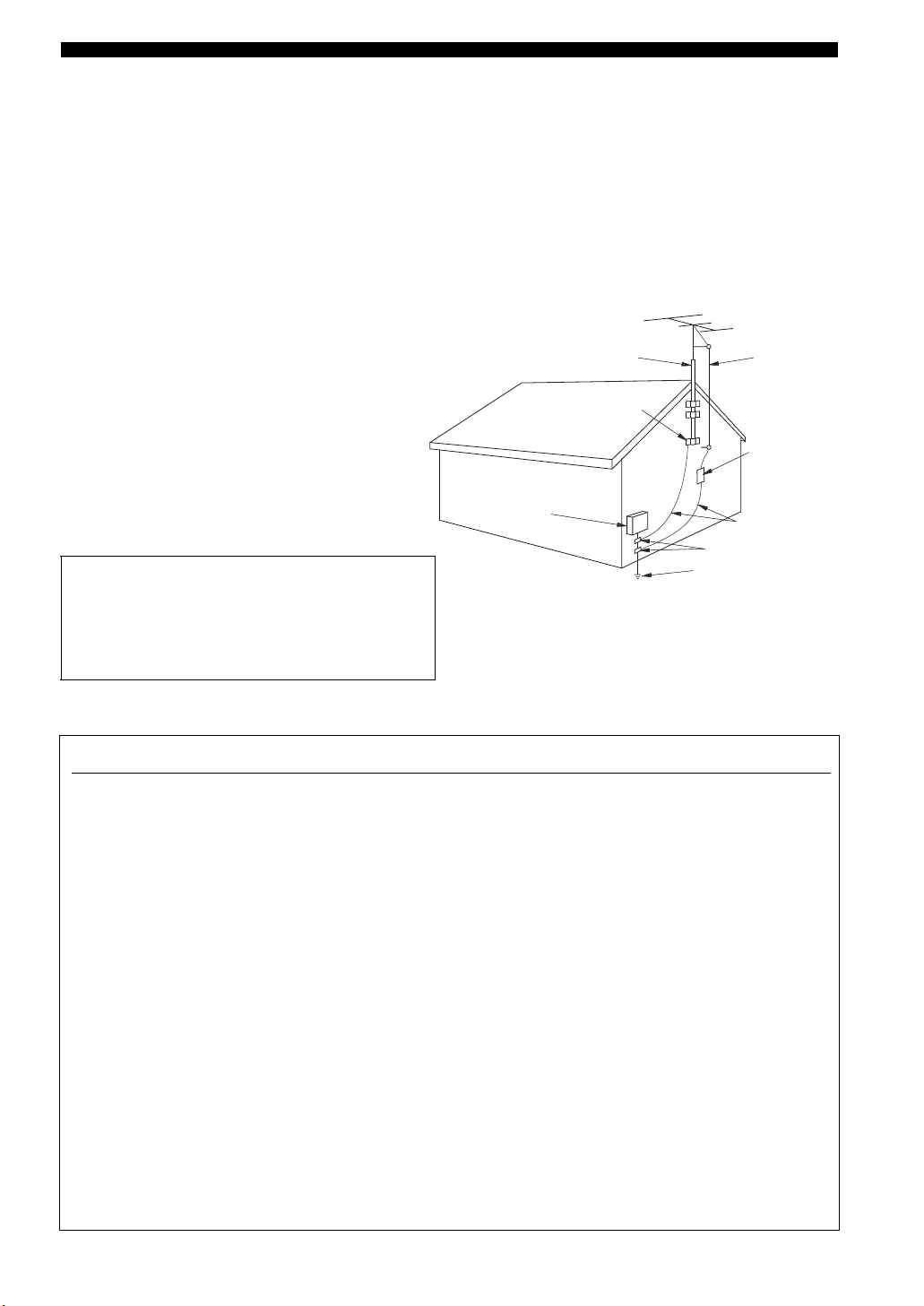
24 Outdoor Antenna Grounding – If an outside antenna or
cable system is connected to the product, be sure the antenna
or cable system is grounded so as to provide some
protection against voltage surges and built-up static charges.
Article 810 of the National Electrical Code, ANSI/NFPA 70,
provides information with regard to proper grounding of the
mast and supporting structure, grounding of the lead-in wire
to an antenna discharge unit, size of grounding conductors,
location of antenna discharge unit, connection to grounding
electrodes, and requirements for the grounding electrode.
EXAMPLE OF ANTENNA GROUNDING
ANTENNA
LEAD IN
WIRE
ANTENNA
DISCHARGE UNIT
(NEC SECTION 810–20)
GROUNDING CONDUCTORS
(NEC SECTION 810–21)
GROUND CLAMPS
ELECTRIC
SERVICE
EQUIPMENT
NEC – NATIONAL ELECTRICAL CODE
MAST
GROUND
CLAMP
POWER SERVICE GROUNDING
ELECTRODE SYSTEM
(NEC ART 250. PART H)
FCC INFORMATION (for US customers)
1 IMPORTANT NOTICE: DO NOT MODIFY THIS
UNIT!
This product, when installed as indicated in the
instructions contained in this manual, meets FCC
requirements. Modifications not expressly approved by
Yamaha may void your authority, granted by the FCC, to
use the product.
2 IMPORTANT: When connecting this product to
accessories and/or another product use only high quality
shielded cables. Cable/s supplied with this product MUST
be used. Follow all installation instructions. Failure to
follow instructions could void your FCC authorization to
use this product in the USA.
3 NOTE: This product has been tested and found to comply
with the requirements listed in FCC Regulations, Part 15
for Class “B” digital devices. Compliance with these
requirements provides a reasonable level of assurance that
your use of this product in a residential environment will
not result in harmful interference with other electronic
devices.
This equipment generates/uses radio frequencies and, if
not installed and used according to the instructions found
in the users manual, may cause interference harmful to the
operation of other electronic devices.
Compliance with FCC regulations does not guarantee that
interference will not occur in all installations. If this
product is found to be the source of interference, which
can be determined by turning the unit “OFF” and “ON”,
please try to eliminate the problem by using one of the
following measures:
Relocate either this product or the device that is being
affected by the interference.
Utilize power outlets that are on different branch (circuit
breaker or fuse) circuits or install AC line filter/s.
In the case of radio or TV interference, relocate/reorient
the antenna. If the antenna lead-in is 300 ohm ribbon lead,
change the lead-in to coaxial type cable.
If these corrective measures do not produce satisfactory
results, please contact the local retailer authorized to
distribute this type of product. If you can not locate the
appropriate retailer, please contact Yamaha Electronics
Corp., U.S.A. 6660 Orangethorpe Ave., Buena Park, CA
90620.
The above statements apply ONLY to those products
distributed by Yamaha Corporation of America or its
subsidiaries.
Caution-ii En

CAUTION: READ THIS BEFORE OPERATING YOUR UNIT.
Caution: Read this before operating your unit.
1 To assure the finest performance, please read this manual
carefully. Keep it in a safe place for future reference.
2 Install this sound system in a well ventilated, cool, dry, clean
place – away from direct sunlight, heat sources, vibration,
dust, moisture, and/or cold. Allow ventilation space of at least
30 cm on the top, 20 cm on the left and right, and 20 cm on
the back of this unit.
3 Locate this unit away from other electrical appliances, motors,
or transformers to avoid humming sounds.
4 Do not expose this unit to sudden temperature changes from
cold to hot, and do not locate this unit in a environment with
high humidity (i.e. a room with a humidifier) to prevent
condensation inside this unit, which may cause an electrical
shock, fire, damage to this unit, and/or personal injury.
5 Avoid installing this unit where foreign object may fall onto
this unit and/or this unit may be exposed to liquid dripping or
splashing. On the top of this unit, do not place:
– Other components, as they may cause damage and/or
discoloration on the surface of this unit.
– Burning objects (i.e. candles), as they may cause fire,
damage to this unit, and/or personal injury.
– Containers with liquid in them, as they may fall and liquid
may cause electrical shock to the user and/or damage to
this unit.
6 Do not cover this unit with a newspaper, tablecloth, curtain,
etc. in order not to obstruct heat radiation. If the temperature
inside this unit rises, it may cause fire, damage to this unit,
and/or personal injury.
7 Do not plug in this unit to a wall outlet until all connections
are complete.
8 Do not operate this unit upside-down. It may overheat,
possibly causing damage.
9 Do not use force on switches, knobs and/or cords.
10 When disconnecting the power cable from the wall outlet,
grasp the plug; do not pull the cord.
11 Do not clean this unit with chemical solvents; this might
damage the finish. Use a clean, dry cloth.
12 Only voltage specified on this unit must be used. Using this
unit with a higher voltage than specified is dangerous and may
cause fire, damage to this unit, and/or personal injury. Yamaha
will not be held responsible for any damage resulting from use
of this unit with a voltage other than specified.
13 To prevent damage by lightning, keep the power cord and
outdoor antennas disconnected from a wall outlet or the unit
during a lightning storm.
14 Do not attempt to modify or fix this unit. Contact qualified
Yamaha service personnel when any service is needed. The
cabinet should never be opened for any reasons.
15 When not planning to use this unit for long periods of time
(i.e. vacation), disconnect the AC power plug from the wall
outlet.
16 Install this unit near the AC outlet and where the AC power
plug can be reached easily.
17 Be sure to read the “Troubleshooting” section on common
operating errors before concluding that this unit is faulty.
18 Before moving this unit, press STANDBY/ON to set this unit
in the standby mode, and disconnect the AC power plug from
the wall outlet.
19 VOLTAGE SELECTOR (Asia and General models only)
The VOLTAGE SELECTOR on the rear panel of this unit
must be set for your local main voltage BEFORE plugging
into the AC wall outlet.
Voltages are 110–120/220–240 V AC, 50/60 Hz.
20 The batteries shall not be exposed to excessive heat such as
sunshine, fire or like.
WAR NING
TO REDUCE THE RISK OF FIRE OR ELECTRIC
SHOCK, DO NOT EXPOSE THIS UNIT TO RAIN
OR MOISTURE.
This unit is not disconnected from the AC power
source as long as it is connected to the wall outlet, even
if this unit itself is turned off by STANDBY/ON. This
state is called the standby mode. In this state, this unit
is designed to consume a very small quantity of power.
FOR CANADIAN CUSTOMERS
To prevent electric shock, match wide blade of plug to
wide slot and fully insert.
This Class B digital apparatus complies with Canadian
ICES-003.
POUR LES CONSOMMATEURS CANADIENS
Pour éviter les chocs électriques, introduire la lame la
plus large de la fiche dans la borne correspondante de
la prise et pousser jusqu’au fond.
Cet appareil numérique de la classe B est conforme à
la norme NMB-003 du Canada.
IMPORTANT
Please record the serial number of this unit in the space
below.
MODEL:
Serial No.:
The serial number is located on the rear of the unit.
Retain this Owner’s Manual in a safe place for future
reference.
Caution-iii En

Contents
INTRODUCTION
Features …………………………………………………………. 2
Getting started ……………………………………………….. 3
Quick start guide ……………………………………………. 4
Preparation: Check the items ………………………………. 4
Step 1: Set up your speakers ……………………………….. 5
Step 2: Connect your DVD player
and other components…………………………………….. 6
Step 3: Turn on the power and
press SCENE 1 button ……………………………………. 8
What do you want to do with this unit? ………………… 9
PREPARATION
Connections ………………………………………………….. 10
Rear panel ………………………………………………………. 10
Placing speakers………………………………………………. 11
Connecting speakers ………………………………………… 12
Setting the speaker impedance
(U.S.A. and Canada models only) ………………….. 13
Information on jacks and cable plugs …………………. 14
Connecting video components…………………………… 15
Connecting audio components…………………………… 17
Connecting the FM and AM antennas ………………… 18
Connecting the power cable………………………………. 18
Turning on and off the power ……………………………. 18
Front panel display ………………………………………….. 19
Basic setup ……………………………………………………. 21
ADVANCED OPERATION
Set menu ………………………………………………………..43
Using set menu ……………………………………………….. 44
1 SOUND MENU……………………………………………. 45
2 INPUT MENU……………………………………………… 48
3 OPTION MENU…………………………………………… 50
Remote control features………………………………….51
Using remote control on the SCENE feature……….. 51
Controlling this unit, a TV, or other components …. 52
Setting remote control codes …………………………….. 54
Advanced setup………………………………………………55
ADDITIONAL INFORMATION
Troubleshooting……………………………………………..56
Glossary…………………………………………………………61
Specifications …………………………………………………63
Index ……………………………………………………………..64
APPENDIX
(at the end of this manual)
Front panel……………………………………………………….i
Remote control ………………………………………………. ii
List of remote control codes …………………………… iii
PREPARATIONINTRODUCTION
OPERATION
BASIC
OPERATION
ADVANCED
BASIC OPERATION
Selecting the SCENE templates……………………… 23
Selecting the desired SCENE template……………….. 23
Creating your original SCENE templates ……………. 26
Playback ………………………………………………………. 27
Basic operations………………………………………………. 27
Additional operations……………………………………….. 28
Sound field programs ……………………………………. 31
Sound field program descriptions ………………………. 31
FM/AM tuning ……………………………………………… 34
Automatic tuning …………………………………………….. 34
Manual tuning …………………………………………………. 34
Automatic preset tuning……………………………………. 35
Manual preset tuning ……………………………………….. 35
Selecting preset stations……………………………………. 36
Exchanging preset stations ……………………………….. 36
XM Satellite Radio tuning …………………………….. 37
Connecting the XM Mini-Tuner Dock ……………….. 37
Activating XM Satellite Radio ………………………….. 38
Basic XM Satellite Radio operations………………….. 38
Setting XM Satellite Radio preset channels ………… 40
Displaying the XM Satellite Radio information…… 41
Recording …………………………………………………….. 42
About this manual
• y indicates a tip for your operation.
• Some operations can be performed by using either the
buttons on the front panel or the ones on the remote
control. In case the button names differ between the front
panel and the remote control, the button name on the
remote control is given in parentheses.
• This manual is printed prior to production. Design and
specifications are subject to change in part as a result of
improvements, etc. In case of differences between the
manual and product, the product has priority.
•“1STANDBY/ON” or “AMULTI CH IN” (example)
indicates the name of the parts on the front panel or the
remote control. Refer to the attached sheet or the top pages
of this manual for the information about each position of
the parts.
•
The symbol “☞ ” with page number(s) indicates the
corresponding reference page(s).
INFORMATION
ADDITIONAL
APPENDIX
English
1 En
Features
Features
Built-in 5-channel power amplifier
◆ Minimum RMS output power
[U.S.A. and Canada models]
(1 kHz, 0.9% THD, 8 Ω)
Front: 100 W + 100 W
Center: 100 W
Surround: 100 W + 100 W
[Other models]
(1 kHz, 0.9% THD, 6 Ω)
Front: 100 W + 100 W
Center: 100 W
Surround: 100 W + 100 W
SCENE select function
◆ Preset SCENE templates for various situations
◆ 4 original SCENE templates for customizing capability
Decoders and DSP circuits
◆ Proprietary Yamaha technology for the creation of multi-
channel surround sound
◆ Compressed Music Enhancer mode to improve the sound
quality of compression artifacts (such as the MP3 format) to
that of a high-quality stereo
◆ Dolby Digital decoder
◆ Dolby Pro Logic/Dolby Pro Logic II decoder
◆ DTS decoder
◆ Neural Surround decoder
(U.S.A. and Canada models only)
◆ Virtual CINEMA DSP
◆ SILENT CINEMA
™
Sophisticated FM/AM tuner
◆ 40-station random and direct preset tuning
◆ Automatic preset tuning
XM Satellite Radio
(U.S.A. and Canada models only)
◆ XM Satellite Radio tuning capability (using the “XM Mini-
Tuner Dock” sold separately)
◆ Neural Surround decoder to play back the XM HD content of
XM Satellite Radio broadcasts in multi-channels, resulting in
a full surround sound experience
Other features
◆ 192-kHz/24-bit D/A converter
◆ 6 additional input jacks for discrete multi-channel input
◆ Component video input/output capability
(3 COMPONENT VIDEO INs and 1 MONITOR OUT)
◆ Optical and coaxial digital audio signal jacks
◆ Sleep timer
◆ Cinema and music night listening modes
◆ Remote control with preset remote control codes
Manufactured under license from Dolby Laboratories.
“Dolby”, “Pro Logic”, and the double-D symbol are trademarks
of Dolby Laboratories.
“SILENT CINEMA” is a trademark of YAMAHA
CORPORATION.
We Want You Listening For A Lifetime
Yamaha and the Electronic Industries Association’s Consumer
Electronics Group want you to get the most out of your
equipment by playing it at a safe level. One that lets the sound
come through loud and clear without annoying blaring or
distortion – and, most importantly, without affecting your
sensitive hearing.
2 En
“DTS” and “DTS Digital Surround” are registered trademarks of
DTS, Inc.
The XM name and related logos are registered trademarks of XM
Satellite Radio Inc.
Neural Surround
by Neural Audio Corporation.
Since hearing damage from loud sounds is often
undetectable until it is too late, Ya ma h a and the
Electronic Industries Association’s Consumer
Electronics Group recommend you to avoid
prolonged exposure from excessive volume levels.
™
name and related logos are trademarks owned
Getting started
Getting started
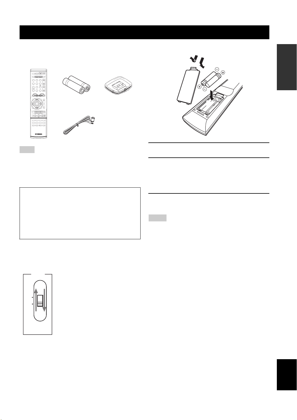
■ Checking the supplied accessories
Check that you received all of the following parts.
Remote control
POWER
STANDBY
POWER
POWER
AVTV
AUDIO SEL
SLEEP MUTE
MULTI CH IN
TUNER
CD MD/CD-R
TV CH
DVD
DTV/CBL DVR
V-AUX XM
TV VOL
AMP
TV MUTE
TV INPUT
SCENE
4321
SRCH MODE
BAND LEVEL
VOLUME
MENU
TITLE
ENTER
RETURN
DISPLAY
XM MEMORY
REC
STRAIGHTENHANCERl PROG h
4321
SUR.DECODENIGHT
81070965
ENT.
Batteries (2)
(AAA, R03, UM-4)
Indoor FM antenna
AM loop antenna
Note
The form of the supplied accessories varies depending on the
models.
■ VOLTAGE SELECTOR
(Asia and General models only)
Caution
The VOLTAGE SELECTOR on the rear panel of this
unit must be set for your local voltage BEFORE
plugging the power cable into the AC wall outlet.
Improper setting of the VOLTAGE SELECTOR may
cause damage to this unit and create a potential fire
hazard.
Select the switch position (upper or lower)
according to your local voltage using a straight
slot screwdriver.
Voltages are 110-120/220-240 V AC, 50/60 Hz.
VOLTAGE
SELECTOR
110V120V
220V240V
■ Installing batteries in the remote control
1
3
2
1 Take off the battery compartment cover.
2 Insert the two supplied batteries
(AAA, R03, UM-4) according to the polarity
markings (+ and –) on the inside of the
battery compartment.
3 Snap the battery compartment cover back
into place.
Notes
• Change all of the batteries if you notice the following condition:
– the operation range of the remote control decreases.
• Do not use an old battery and a new one together.
• Do not use different types of batteries (such as alkaline and
manganese batteries) together. Read the packaging carefully as
these different types of batteries may have the same shape and
color.
• If the batteries have leaked, dispose of them immediately. Avoid
touching the leaked material or letting it come into contact with
clothing, etc. Clean the battery compartment thoroughly before
installing new batteries.
• Do not throw away batteries with general house waste; dispose
of them correctly in accordance with your local regulations.
• If the remote control is without batteries for more than 2
minutes, or if exhausted batteries remain in the remote control,
the contents of the memory may be cleared. When the memory
is cleared, insert new batteries and set up the remote control
code.
INTRODUCTION
3 En
English
Quick start guide
Quick start guide
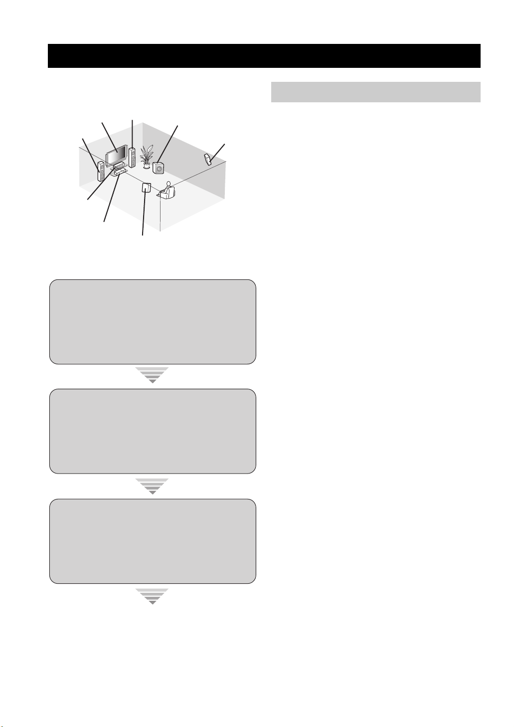
The following steps describe the easiest way to enjoy
DVD movie playback in your home theater.
Front right
Video monitor
Front left
speaker
Center speaker
DVD player
Step 1: Set up your speakers
Step 2: Connect your DVD player
speaker
Surround left
speaker
Subwoofer
Surround right
speaker
☞
and other components
☞
P. 6
P. 5
Preparation: Check the items
In these steps, you need the following supplied
accessories.
❏ Indoor FM antenna
❏ AM loop antenna
The following items are not included in the package of this
unit.
❏ Speakers
❏ Front speakers ……………………………….. 2
❏ Center speaker ……………………………….. 1
❏ Surround speakers …………………………. 2
Select magnetically shielded speakers. The
minimum required speakers are two front speakers.
❏ Active subwoofer ……………………………….. 1
Select an active subwoofer equipped with an RCA
input jack.
❏ Speaker cables …………………………………… 5
❏ Subwoofer cable …………………………………. 1
Select a monaural RCA cable.
❏ DVD player …………………………………………. 1
Select DVD player equipped with coaxial digital
audio output jack and composite video output
jack.
❏ Video monitor ……………………………………… 1
Select a TV monitor, video monitor or projector
equipped with a composite video input jack.
❏ Video cable ………………………………………… 1
Select an RCA composite video cable.
Step 3: Turn on the power and
press SCENE 1 button
Enjoy DVD playback!
4 En
☞
P. 8
❏ Digital coaxial audio cable …………………..1
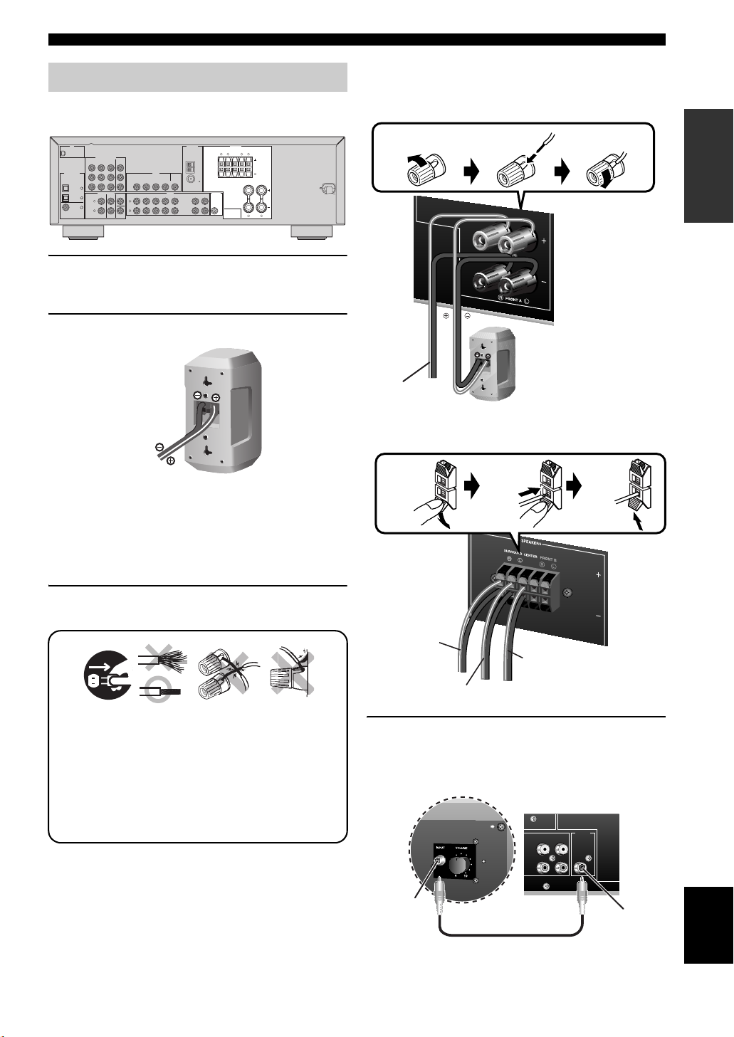
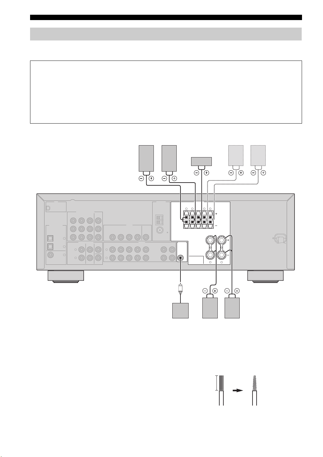
Step 1: Set up your speakers
Place your speakers in the room and connect them to this
unit.
XM
COMPONENT VIDEO
DVD
MONITOR
DTV/CBL DVR
OUT
R
P
DIGITAL INPUT
P
B
OPTICAL
Y
CD
3
MULTI CH INPUT
DTV/
2
CBL
L
1
DVD
R
COAXIAL
DTV/CBL
DVD DVR
DVD
DTV/CBL
CENTER
SURROUNDFRONT
L
R
SUBWOOFER
1 Place your speakers and subwoofer in the
room.
2 Connect speaker cables to each speaker.
VIDEO
MONITOR
IN OUT
OUT
AUDIO OUTPUT
D
CD
V
R
IN
OU
T
ANTENNA
SPEAKERS
SURROUND CENTER FRONT B
LR LR
AM
GND
FM
75
IN
OU
T
MD/
(PL
(REC)
AY)
D-R
C
SUB
WO
O
FER
LR
FRONT A
Quick start guide
Be sure to connect the left channel (L), right channel
(R), “+” (red) and “–” (black) properly.
Front speakers
Loosen Insert Tighten
Front left speaker
To the front right
speaker
Center and surround speakers
INTRODUCTION
Cables are colored or shaped differently, perhaps with
a stripe, groove or ridge. Connect the striped
(grooved, etc.) cable to the “+” (red) terminals of
your speaker. Connect the plain cable to the “–”
(black) terminals.
3 Connect each speaker cable to the
corresponding speaker terminal of this unit.
12 3 4
1 Make sure that this unit and the subwoofer are
unplugged from the AC wall outlets.
2 Twist the exposed wires of the speaker cables
together to prevent short circuits.
3 Do not let the bare speaker wires touch each other.
4 Do not let the bare speaker wires touch any metal
part of this unit.
Press down
To the surround
right speaker
To the surround
left speaker
Insert
To the center
speaker
Release
4 Connect the subwoofer cable to the input
jack of the subwoofer and the SUBWOOFER
OUTPUT jack of this unit.
AV receiverSubwoofer
OUTPUT
MD/
IN
OUT
(PLAY)
(REC)
CD-R
SUB
WOOFER
Input jack
Subwoofer cable
SUBWOOFER
OUTPUT jack
5 En
English
Quick start guide
L/MONO
AUDIO AUDIO
COLOR STREAM HD
VIDEO
VIDEO-1 IN IN
S-VIDEO
RYP
BPR
RL/MONO
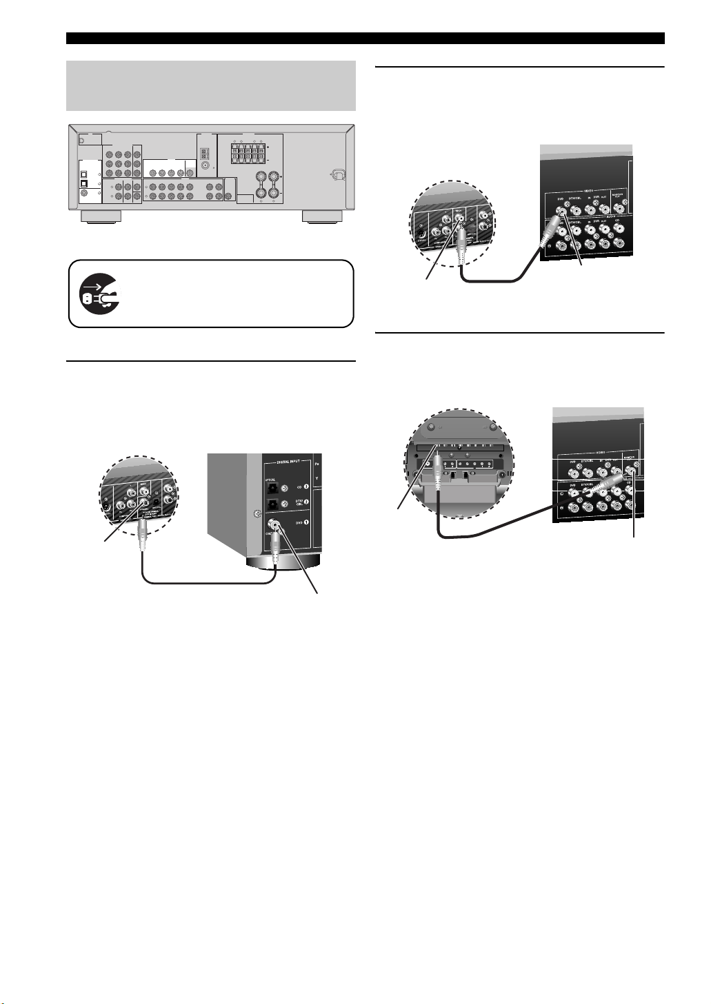
Step 2: Connect your DVD player
and other components
XM
COMPONENT VIDEO
DVD
MONITOR
DTV/CBL DVR
OUT
R
P
DIGITAL INPUT
P
B
OPTICAL
Y
CD
3
MULTI CH INPUT
DTV/
2
CBL
L
1
DVD
R
COAXIAL
DTV/CBL
DVD DVR
DVD
DTV/CBL
CENTER
SURROUNDFRONT
L
R
SUBWOOFER
VIDEO
MONITOR
IN OUT
OUT
AUDIO OUTPUT
D
CD
V
R
IN
OU
T
ANTENNA
Make sure that this unit and the DVD
player are unplugged from the AC wall
outlets.
1 Connect the digital coaxial audio cable to the
digital coaxial audio output jack of your DVD
player and the DVD DIGITAL INPUT COAXIAL
jack of this unit.
DVD player
SPEAKERS
SURROUND CENTER FRONT B
LR LR
AM
GND
FM
75
IN
OU
T
MD/
(PLAY)
(REC)
CD-R
SUB
WO
O
FER
LR
FRONT A
AV receiver
2 Connect the video cable to the composite
video output jack of your DVD player and the
DVD VIDEO jack of this unit.
AV receiver
DVD player
Composite video
output jack
Video cable
DVD VIDEO jack
3 Connect the video cable to the video input
jack of your video monitor and the VIDEO
MONITOR OUT jack of this unit.
Video monitor AV receiver
Digital coaxial
audio output
jack
Digital coaxial audio
cable
DVD DIGITAL INPUT
COAXIAL jack
Video input
jack
Video cable
VIDEO MONITOR OUT
jack
6 En
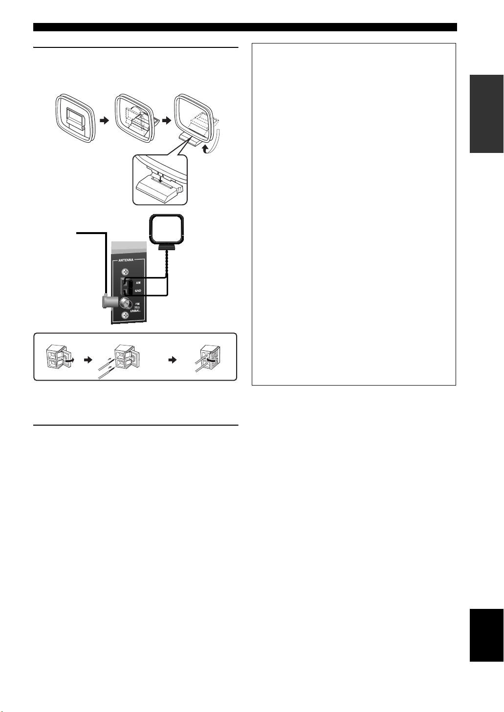
Quick start guide
4 Connect the FM and AM antennas to this
unit.
See page 18 for the details.
Indoor FM antenna
Press and hold Insert Release
AM loop antenna
■ For further connections
• Using the other kind of speaker
combinations
☞
P. 11
• Connecting a video monitor and
DVD player
☞
P. 15
• Connecting a cable TV/satellite tuner and
DVD recorder
☞
P. 15
• Connecting to the COMPONENT VIDEO
jacks
☞
P. 16
• Using the VIDEO AUX jacks on the front
panel
☞
P. 16
• Connecting a CD player and an MD
recorder
☞
P. 17
• Connecting a DVD player via analog
multi-channel audio connection
☞
P. 17
• Connecting an outdoor FM/AM antenna
☞
P. 18
• Connecting the XM Mini-Tuner Dock
☞
P. 37
INTRODUCTION
y
The wire of the AM loop antenna does not have any polarity and
you can connect either end of the wire to AM or GND terminal.
5 Connect the power plug of this unit and other
components into the AC wall outlet.
English
7 En
Quick start guide
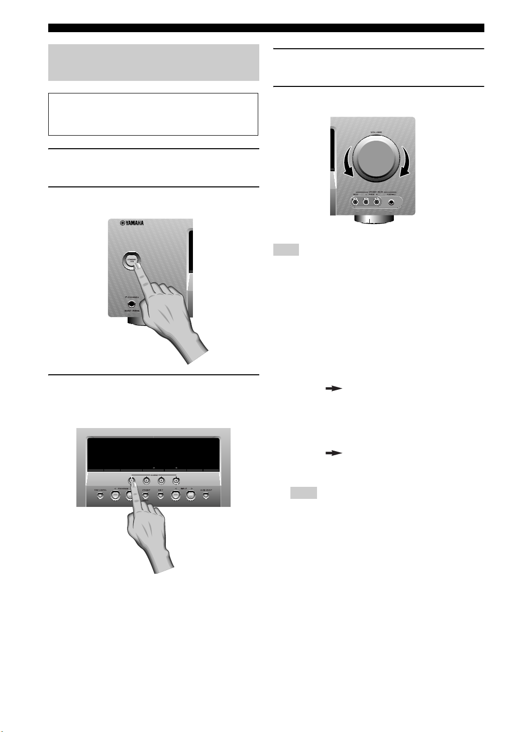
Step 3: Turn on the power and
press SCENE 1 button
Check the type of the connected speakers.
If the speakers are 6 ohm speakers, set “SP IMP.” to
“6ΩMIN” before using this unit (see page 13).
1 Turn on the video monitor connected to this
unit.
2 Press
1
STANDBY/ON on the front panel.
4 Start playback of the desired DVD on your
player.
5 Rotate
Note
When you change the input source or sound field program, the
SCENE mode is deactivated and the indicator on the SCENE
button turns off.
■ Using the other SCENE buttons
In the following cases, try pressing the corresponding
SCENE button to enjoy playback of the desired sources.
8
VOLUME to adjust the volume.
3 Press
F
SCENE 1.
“DVD Viewing” appears in the front panel display,
and this unit automatically optimize own status for
the DVD playback.
SEARCH MODE
PRESET/TUNING
EDIT
FM / AM A/B/C/D/E
CATEGORY
A / B / C / D / E MEMORY
DISPLAY
TUNING AUTO/MAN’L
y
The indicator on the selected SCENE button lights up while
this unit is in the SCENE mode.
Case A: “I want to listen to a music disc from the
connected DVD player as the back ground
music for this room…”
Press FSCENE 2 (or
E
SCENE 2) to select “Disc
Listening”.
Case B: “I want to watch a TV program…”
Press FSCENE 3 (or
E
SCENE 3) to select “TV
Viewing”.
Note
To use the “TV Viewing” template, you must connect a
cable TV or satellite tuner to this unit in advance. See
page 15 for details.
8 En
Case C: “I want to listen to a music program from
the FM radio station…”
Press FSCENE 4 (or
E
SCENE 4) to select “Radio
Listening”.
Notes
• To use the “Radio Listening” template, you must tune into
the desired radio station in advance. See pages 34 to 36 for
tuning information.
• To achieve the best possible reception, orient the
connected AM loop antenna, or adjust the position of the
end of the indoor FM antenna.
y
If you cannot find the desired situation, you can select and change
the assigned SCENE template for the SCENE buttons. See
page 23 for details.
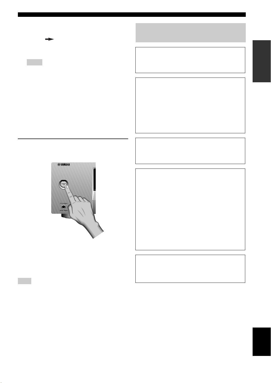
■ After using this unit…
Quick start guide
What do you want to do with this
unit?
■ Customizing the SCENE templates
• Using various SCENE templates
☞
P. 23
■ Using various input sources
• Basic controls of this unit
☞
P. 27
• Enjoying FM/AM radio programs
☞
P. 34
• Enjoying XM Satellite Radio programs
☞
P. 37
INTRODUCTION
Press 1STANDBY/ON on the front panel to set
this unit to the standby mode.
This unit is set to the standby mode. In the standby mode,
this unit consumes a small amount of power in order to
receive infrared signals from the remote control. To turn
on this unit from the standby mode, press 1STANDBY/
ON (or LPOWER) on the front panel. See page 18 for
details.
Note
In the standby mode, this unit consumes a small amount of power
in order to receive infrared signals from the remote control.
■ Using various sound features
• Using various sound field programs
☞
P. 31
■ Adjusting the parameters of this unit
• Optimizing the speaker parameters for your
listening room (BASIC SETUP)
☞
P. 21
• Manually adjusting various parameters of
this unit
☞
P. 43
• Setting the remote control
☞
P. 51
• Adjusts the advanced parameters
☞
P. 55
■ Additional features
Automatically turning off this unit
☞
P. 30
9 En
English
Connections
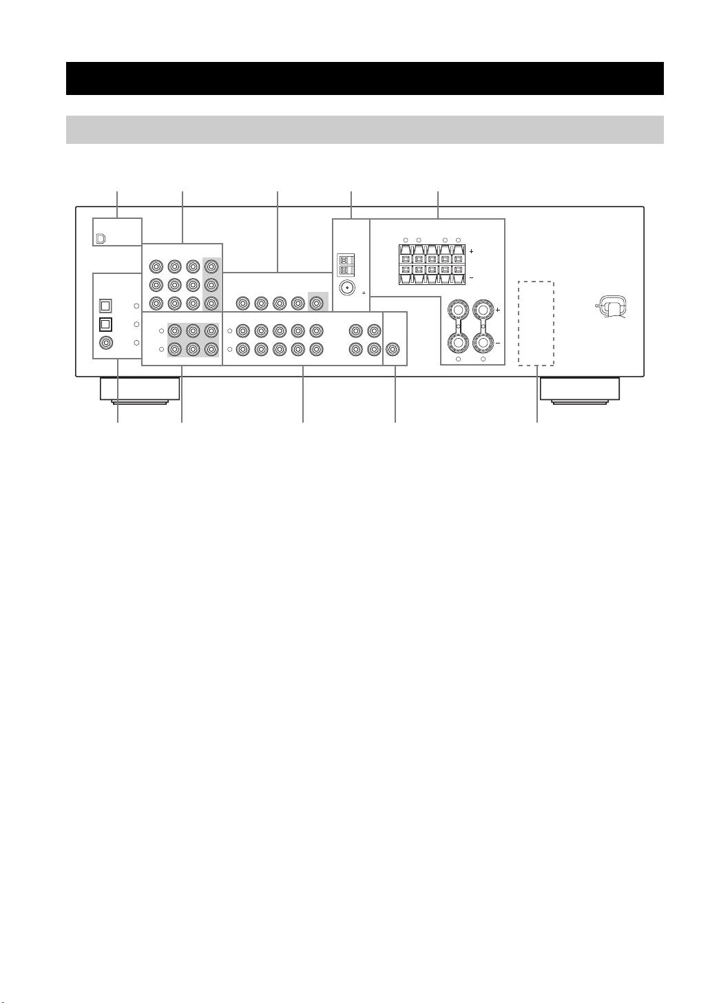
Rear panel
Connections
1 3 4 5
XM
DIGITAL INPUT
OPTICAL
CD
DTV/
CBL
DVD
COAXIAL
2
COMPONENT VIDEO
DTV/CBL DVR
MULTI CH INPUT
MONITOR
OUT
VIDEO
DVD DVR
DTV/CBL
DVD
/CBL
V
CENTER
SURROUNDFRONT
SUBWOOFER
DT
L
R
MONITOR
IN OUT
OUT
AUDIO OUTPUT
D
C
D
VR
IN
O
UT
DVD
P
R
P
B
Y
3
2
L
1
R
1 XM jack (U.S.A. and Canada models only)
See page 37 for connection information.
2 COMPONENT VIDEO jacks
See page 16 for connection information.
3 VIDEO jacks
See pages 15 for connection information.
4 ANTENNA terminals
See page 18 for connection information.
5 SPEAKERS terminals
See page 12 for connection information.
ANTENNA
AM
GND
FM
75
IN
O
UT
/
D
M
(PLAY)
(
R
C
E
)
CD-R
SURROUND CENTER FRONT B
R
S
UB
W
OOF
ER
L
SPEAKERS
L
R
L
R
FRONT A
8 AUDIO jacks
See pages 15 and 17 for connection information.
9 SUBWOOFER OUTPUT jack
See page 12 for connection information.
0 VOLTAGE SELECTOR
(Asia and General models only)
See page 3 for details.
(U.S.A. model)
6 DIGITAL INPUT jacks
See page 17 for connection information.
7 MULTI CH INPUT jacks
See page 17 for connection information.
10 En
Connections
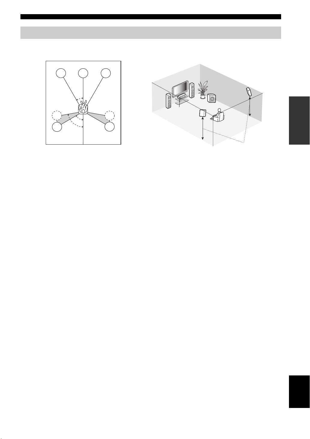
Placing speakers
The speaker layout below shows the speaker setting we recommend. You can use it to enjoy CINEMA DSP and multichannel audio sources.
FL
SL
SL
C
30˚
60˚
80˚
FR
FR
SR
SR
FL
SW
C
SL
SR
1.8 m (6 ft)
Front left and right speakers (FL and FR)
The front speakers are used for the main source sound plus effect sounds. Place these speakers at an equal distance from the
ideal listening position. The distance of each speaker from each side of the video monitor should be the same.
Center speaker (C)
The center speaker is for the center channel sounds (dialog, vocals, etc.). If for some reason it is not practical to use a
center speaker, you can do without it. Best results, however, are obtained with the full system.
Surround left and right speakers (SL and SR)
The surround speakers are used for effect and surround sounds.
Subwoofer (SW)
The use of a subwoofer with a built-in amplifier, such as the Yamaha Active Servo Processing Subwoofer System, is
effective not only for reinforcing bass frequencies from any or all channels, but also for high fidelity sound reproduction
of the LFE (low-frequency effect) channel included in Dolby Digital and DTS sources. The position of the subwoofer is
not so critical, because low bass sounds are not highly directional. But it is better to place the subwoofer near the front
speakers. Turn it slightly toward the center of the room to reduce wall reflections.
PREPARATION
11 En
English
Connections
Connecting speakers
Be sure to connect the left channel (L), right channel (R), “+” (red) and “–” (black) properly. If the connections are faulty,
this unit cannot reproduce the input sources accurately.
Caution
• Use speakers with the specified impedance shown on the rear panel of this unit.
• If you are to use 6 ohm speakers, be sure to set “SP IMP.” to “6Ω MIN” before using this unit (see page 13).
• Before connecting the speakers, make sure that this unit is turned off.
• Do not let the bare speaker wires touch each other or let them touch any metal part of this unit. This could damage
this unit and/or speakers.
• Use magnetically shielded speakers. If this type of speakers still creates the interference with the monitor, place the
speakers away from the monitor.
OPTICAL
COAXIAL
XM
DIGITAL INPUT
Surround speakers
LeftRight
Front speakers (B)
LeftRight
Center
speaker
ANTENNA
COMPONENT VIDEO
DTV/CBL DVR
MULTI CH INPUT
MONITOR
OUT
VIDEO
DVD DVR
DTV/CBL
DVD
/CBL
V
CENTER
SURROUNDFRONT
SUBWOOFER
DT
L
R
MONITOR
IN OUT
OUT
AUDIO OUTPUT
D
C
D
VR
IN
O
UT
AM
GND
FM
75
IN
O
UT
D/
M
(PLAY
R
(
E
C
)
)
CD-R
DVD
P
R
P
B
Y
CD
3
DTV/
2
CBL
L
1
DVD
R
SURROUND CENTER FRONT B
S
UB
W
OOF
E
R
SPEAKERS
LR LR
FRONT A
LR
(U.S.A. model)
■ Before connecting to the SPEAKERS
terminal
A speaker cord is actually a pair of insulated cables
running side by side. Cables are colored or shaped
differently, perhaps with a stripe, groove or ridges.
Connect the striped (grooved, etc.) cable to the “+” (red)
terminals of this unit and your speaker. Connect the plain
cable to the “–” (black) terminals.
12 En
Subwoofer
LeftRight
Front speakers (A)
Remove approximately 10 mm (3/8”) of insulation
from the end of each speaker cable and then
twist the bare wires of the cable together to
prevent short circuits.
10 mm (3/8”)
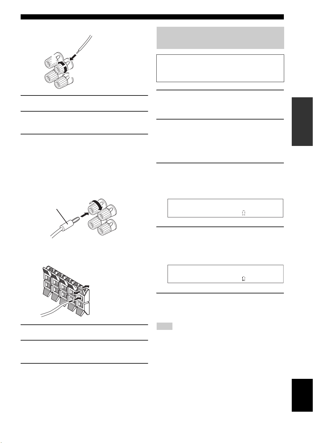
■ Connecting to the FRONT A terminals
2
1
Red: positive (+)
Black: negative (–)
3
Connections
Setting the speaker impedance
(U.S.A. and Canada models only)
Caution
If you are to use 6 ohm speakers, set “SP IMP.” to “6Ω
MIN” as follows BEFORE using this unit.
1 Loosen the knob.
2 Insert the bare end of the speaker wire into
the hole on the terminal.
3 Tighten the knob to secure the wire.
Connecting the banana plug
(except Europe, Korea and Asia models)
The banana plug is a single-pole electrical connector
widely used to terminate speaker cables. First, tighten the
knob and then insert the banana plug connector into the
end of the corresponding terminal.
Banana plug
■ Connecting to the FRONT B, CENTER,
and SURROUND terminals
1 Make sure this unit is turned off.
See page 18 for details about turning on or off this
unit.
2 Press and hold
then press 1STANDBY/ON to turn on this
unit.
This unit turns on, an the advanced setup menu
appears in the front panel display.
3 Press
4 Press
A
PROGRAM l / h repeatedly to
select “SP IMP.”.
The following display appears in the front panel
display.
B
STRAIGHT repeatedly to select “6Ω
MIN”.
The following display appears in the front panel
display.
0
TONE CONTROL and
SP IMP.- 8 MIN
PREPARATION
Red: positive (+)
Black: negative (–)
1 Press down the tab.
2 Insert the bare end of the speaker wire into
the hole on the terminal.
3 Release the tab to secure the wire.
SP IMP.- 6 MIN
5 Press
Note
The setting you made is reflected next time you turn on this unit.
1
STANDBY/ON to confirm your
selection and set this unit to the standby
mode.
13 En
English
Connections
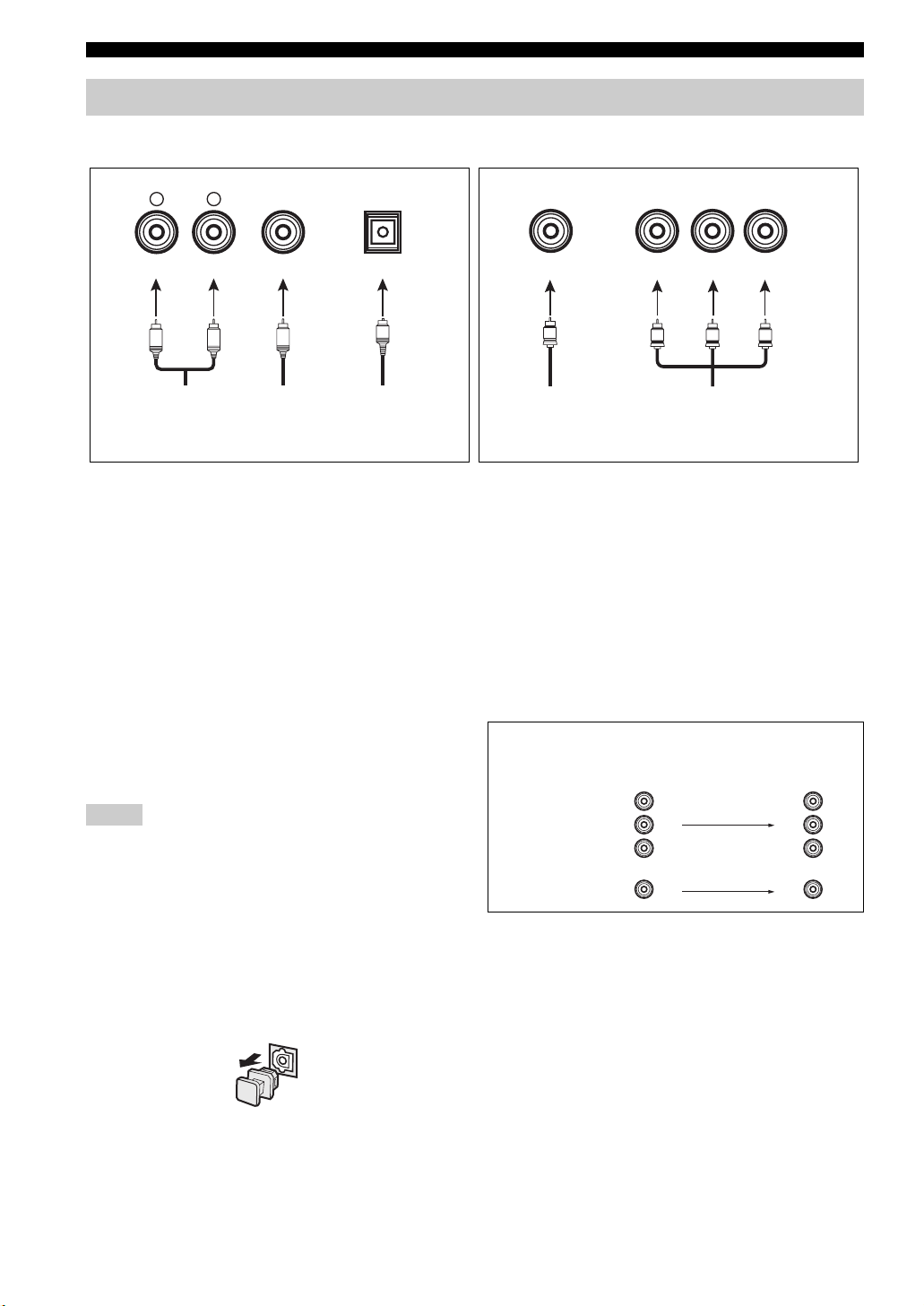
Information on jacks and cable plugs
Audio jacks and cable plugs Video jacks and cable plugs
AUDIO
L
L
Left and right
analog audio
cable plugs
R
(Red)(White) (Orange) (Yellow) (Green) (Blue) (Red)
R
DIGITAL AUDIO
COAXIAL
C
Coaxial
digital audio
cable plug
DIGITAL AUDIO
OPTICAL
O
Optical
digital
audio cable
plug
■ Audio jacks
This unit has three types of audio jacks. Connection
depends on the availability of audio jacks on your other
components.
AUDIO jacks
For conventional analog audio signals transmitted via left
and right analog audio cables. Connect red plugs to the
right jacks and white plugs to the left jacks.
DIGITAL AUDIO COAXIAL jacks
For digital audio signals transmitted via coaxial digital
audio cables.
DIGITAL AUDIO OPTICAL jacks
For digital audio signals transmitted via optical digital
audio cables.
Notes
• You can use the digital jacks to input PCM, Dolby Digital and
DTS bitstreams. All digital input jacks are compatible with
digital signals with up to 96 kHz of sampling frequency.
• This unit handles digital and analog signals independently. Thus
audio signals input at the digital jacks are not output at the
analog AUDIO OUT (REC) jacks.
• Pull out the cap from the optical jack before you connect the
fiber optic cable. Do not discard the cap. When you are not
using the optical jack, be sure to put the cap back in place. This
cap protects the jack from dust.
VIDEO
V
Composite
video cable
plug
COMPONENT VIDEO
Y PBP
Y
PB
Component
video cable
plugs
R
P
R
■ Video jacks
This unit has two types of video jacks. Connection
depends on the availability of input jacks on your video
monitor.
VIDEO jacks
For conventional composite video signals transmitted via
composite video cables.
COMPONENT VIDEO jacks
For component signals, separated into the luminance (Y)
and chrominance (P
separate wires of component video cables.
Video signal flow for MONITOR OUT
COMPONENT
VIDEO
VIDEO
B, PR) video signals transmitted on
Input
PR
B
P
Y
Output
(MONITOR OUT)
P
R
B
P
Y
14 En
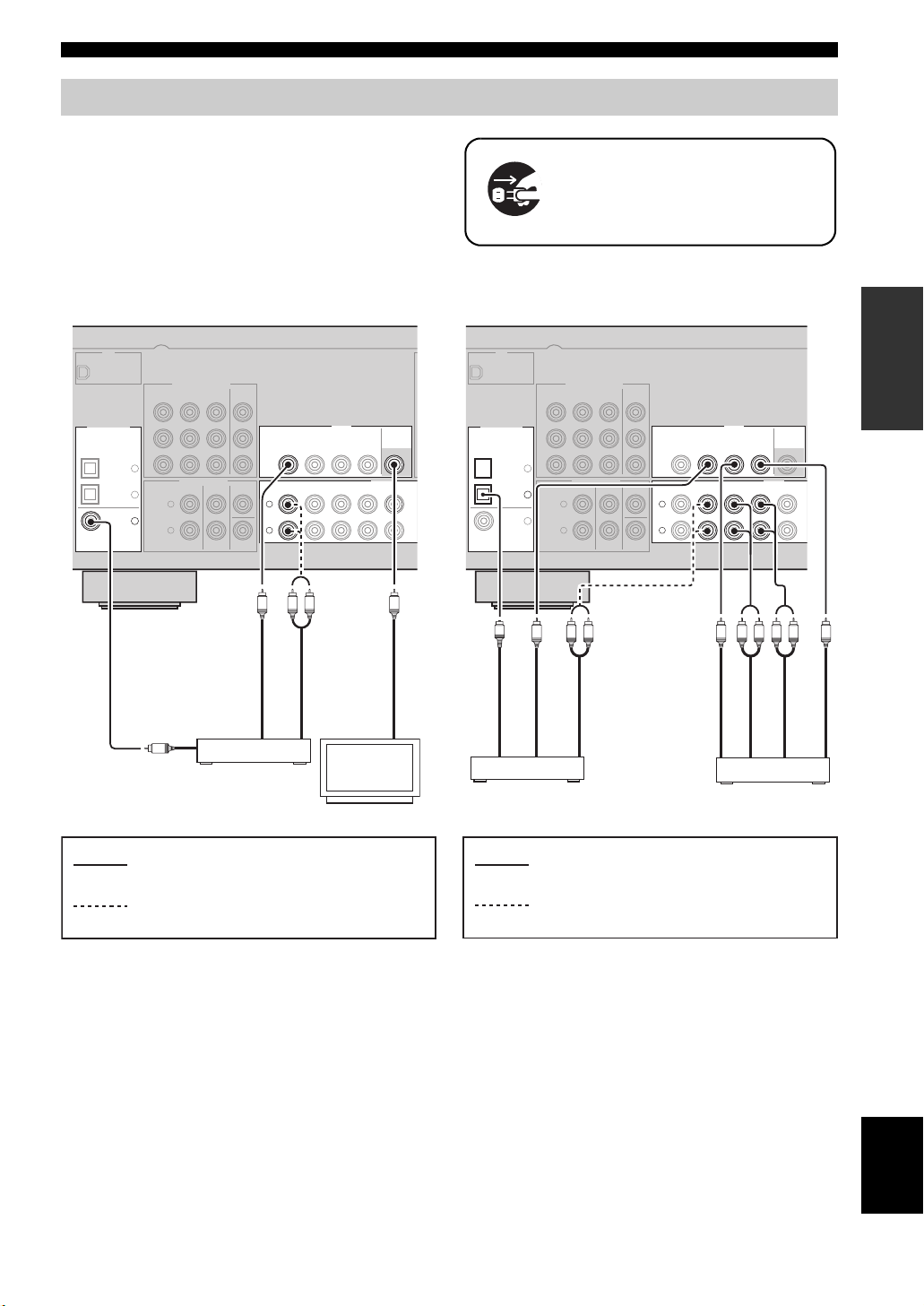
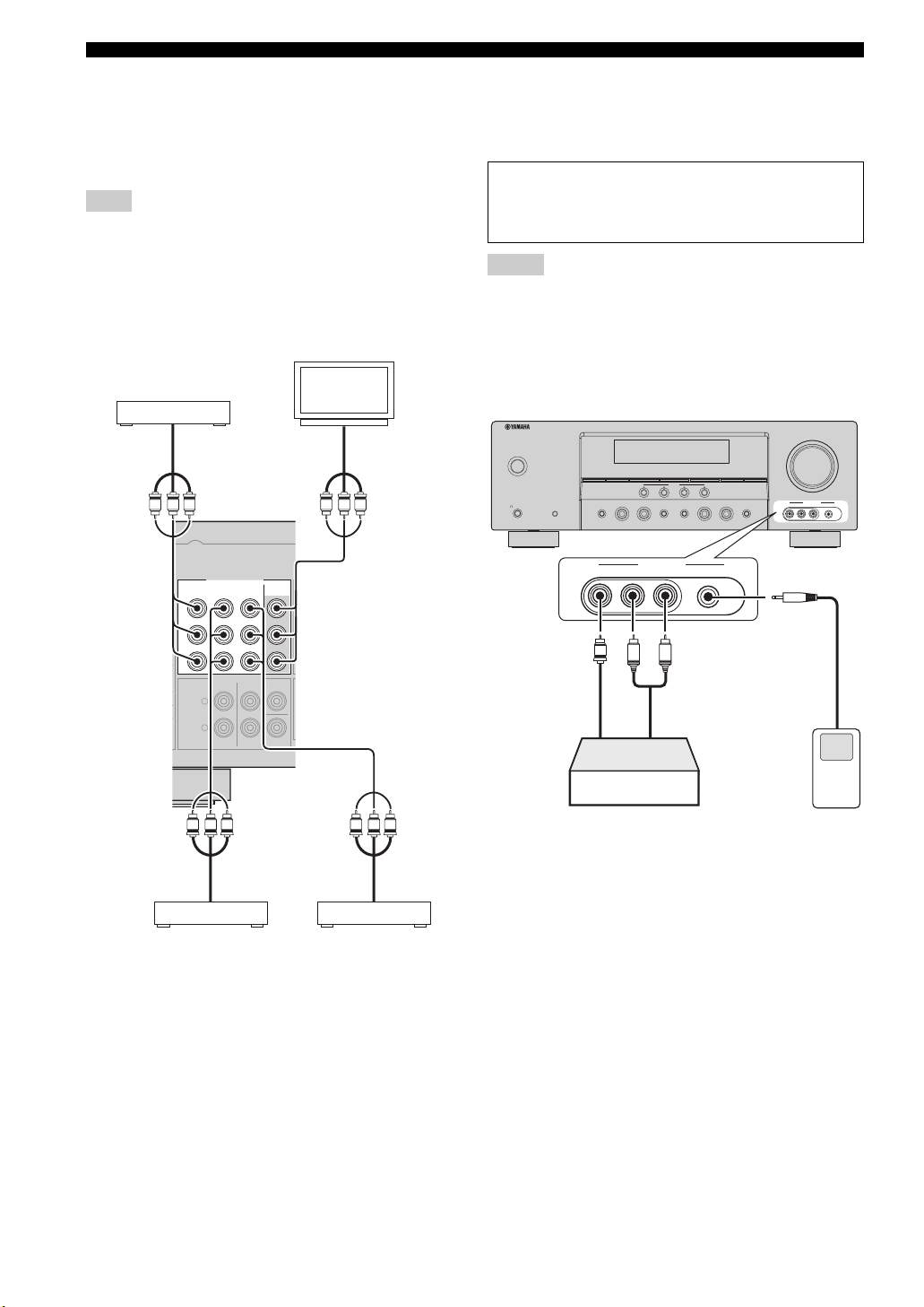
Connecting video components
Connect the video components as follows.
y
You can also connect a video monitor, DVD player, digital TV,
and cable TV to this unit using the COMPONENT VIDEO
connection (see page 16).
Connections
Make sure that this unit and other
components are unplugged from the
AC wall outlets.
■ Connecting a video monitor and a DVD
player
XM
COMPONENT VIDEO
OPTICAL
COAXIAL
DIGITAL INPUT
CD
3
DTV/
2
CBL
1
DVD
Audio out
DVD
R
P
P
B
Y
L
R
C
DTV/CBL DVR
MULTI CH INPUT
SURROUNDFRONT
MONITOR
OUT
CENTER
L
R
SUBWOOFER
Video out
DVD p layer
VIDEO
DTV/CBL
DVD DVR
DVD
IN OUT
DTV/CBL
IN
R
L
Audio out
Video monitor
MONITOR
OUT
AUDIO
D
CD
V
R
OUT
VV
Video in
■ Connecting a cable TV/satellite tuner
and a DVD recorder
XM
COMPONENT VIDEO
DIGITAL INPUT
OPTICAL
CD
3
DTV/
2
CBL
1
DVD
COAXIAL
O
Audio out
Cable TV or
Satellite tuner
DVD
R
P
P
B
Y
L
R
L
Video out
DTV/CBL DVR
MULTI CH INPUT
SURROUNDFRONT
R
Audio out
MONITOR
OUT
CENTER
SUBWOOFER
DTV/CBL
DVD DVR
DVD
DTV/CBL
L
R
VIDEO
IN OUT
AUDIO
D
V
R
IN
OUT
LRL
Audio out
Video out
DVD recorder
MONITOR
OUT
CD
R
Audio in
PREPARATION
VVV
Video in
indicates recommended connections
indicates alternative connections
indicates recommended connections
indicates alternative connections
English
15 En
Connections
■ Connecting to the COMPONENT VIDEO
jacks
You can enjoy high-quality pictures by connecting your
video monitor and video source components to this unit
using COMPONENT VIDEO connection.
Note
Be sure to connect your video source components in the same
way you connect your video monitor to this unit. For example, if
you connect your video monitor to this unit using a
COMPONENT VIDEO connection, connect your video source
components to this unit using the COMPONENT VIDEO
connection.
Video monitor
DVD player
Video out
PRPBY
P
R
P
B
Y
COMPONENT VIDEO
DVD
L
R
DTV/CBL DVR MONITOR
MULTI CH INPUT
SURROUNDFRONT
Video in
PRPBY
OUT
CENTER
SUBWOOFER
■ Connecting to the VIDEO AUX jacks on
the front panel
Use the VIDEO AUX jacks on the front panel to connect a
game console or a video camera to this unit.
Caution
Be sure to turn down the volume of this unit and other
components before making connections.
Notes
• To reproduce the source signals input at these jacks, select
“V-AUX” as the input source.
• The audio signals input at the PORTABLE mini jack take
priority over the ones input at the AUDIO L/R jacks.
VOLUME
STANDBY
/ON
PHONES
SILENT CINEMA
EDIT
SEARCH MODE
PRESET/TUNING
FM/AM
SPEAKERS
TONE CONTROL
A/B/OFF
VIDEO L AUDIO R PORTABLE
V
Video
output
CATEGORY
A/B/C/D/E
1234
EFFECT
VIDEO AUX
L
R
Audio
output
l
SCENE
PRESET/TUNING/CH
NIGHTSTRAIGHT
DISPLAY
TUNING AUTO/MAN’L
h
MEMORY
l INPUT hl PROGRAM h
AUDIO SELECT
VIDEO AUX
VIDEO L AUDIO R PORTABLE
3.5 mm
stereo mini
plug
16 En
PRPBY
Video out
Cable TV or
satellite tuner
PRPBY
Video out
DVD recorder
Game console or
video camera
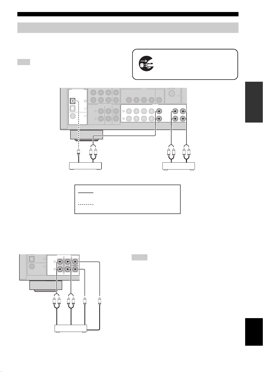
Connecting audio components
Connect the audio components as follows.
■ Connecting a CD player and a CD
recorder/MD recorder
Note
When you connect your CD player via analog and digital
connection, priority is given to the signal input at the DIGITAL
INPUT jack.
DIGITAL INPUT
OPTICAL
COAXIAL
P
B
Y
CD
3
DTV/
CBL
DVD
MULTI CH INPUT
2
L
1
R
CENTER
SURROUNDFRONT
SUBWOOFER
DVD DVR
DTV/CBL MONITOR
DVD
DTV/CBL
L
R
VIDEO
IN OUT
IN
Connections
Make sure that this unit and other
components are unplugged from the
AC wall outlets.
PREPARATION
(PLAY)
FM
75
IN
OUT
MD/
(REC)
CD-R
OUT
AUDIO
DVR
CD
OUT
O
R
L
R
L
R
L
Audio outAudio out Audio inAudio out
CD player CD recorder or
MD recorder
indicates recommended connections
indicates alternative connections
■ Connecting to the MULTI CH INPUT jacks
This unit is equipped with 6 additional input jacks (FRONT L/R, SURROUND L/R, CENTER and SUBWOOFER) for
discrete multi-channel input from a multi-format player, external decoder or sound processor. Connect the output jacks
on your multi-format player or external decoder to the MULTI CH INPUT jacks. Be sure to match the left and right
output jacks to the left and right input jacks for the front and surround channels.
COAXIAL
DTV/
CBL
DVD
MULTI CH INPUT
2
L
1
R
L
CENTER
SURROUNDFRONT
Notes
• When you select the component connected to the MULTI CH
SUBWOOFER
INPUT jacks as the input source (see page 28), this unit
automatically turns off the digital sound field processor, and
you cannot select sound field programs.
• This unit does not redirect signals input at the MULTI CH
INPUT jacks to accommodate for missing speakers. We
recommend that you connect a 5.1-channel speaker system
R
R
L
before using this feature.
Surround out
Front out
Multi-format player or
external decoder
Subwoofer out
Center out
English
17 En
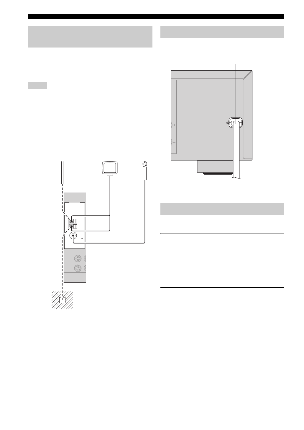
Connections
Connecting the FM and AM
antennas
Both FM and AM indoor antennas are supplied with this
unit. In general, these antennas should provide sufficient
signal strength. Connect each antenna correctly to the
designated terminals.
Notes
• The AM loop antenna should be placed away from this unit.
• A properly installed outdoor antenna provides clearer reception
than an indoor one. If you experience poor reception quality,
install an outdoor antenna. Consult the nearest authorized
Yamaha dealer or service center about outdoor antennas.
• The AM loop antenna should always be connected, even if an
outdoor AM antenna is connected to this unit.
Outdoor AM antenna
Use a 5 to 10 m (16 to 32 ft) of
vinyl-covered wire extended
outdoors from a window.
ANTENNA
UNBAL.
IN
(P
LAY)
AM loop
antenna
(supplied)
AM
GND
FM
75
/
D
M
-R
D
C
Indoor FM
antenna
(supplied)
Connecting the power cable
Once all connections are complete, plug the power cable
into the AC wall outlet.
Power cable
(U.S.A. model)
To the AC wall outlet
Turning on and off the power
■ Turning on this unit
Press 1STANDBY/ON (or LPOWER) to turn
on this unit.
y
When you turn on this unit, there will be a 4 to 5-second delay
before this unit can reproduce sound.
18 En
Ground
For maximum safety and minimum
interference, connect the antenna GND
terminal to a good earth ground. A good
earth ground is a metal stake driven into
moist earth.
■ Set this unit to the standby mode
Press 1STANDBY/ON (or MSTANDBY) to set
this unit to the standby mode.
In the standby mode, this unit consumes a small amount of
power in order to receive infrared signals from the remote
control.

Front panel display
Connections
4 6 81 2 3 7
t
PCM
ENHANCER
q
DIGITAL
q PL
q PL
neural
VIRTUAL
DVR DVD CD
SP
09 B ED
SILENT CINEMA
A B
A
V-AUX DTV/CBL
NIGHT
1 Decoder indicator
Lights up when any of the decoders of this unit functions.
2 ENHANCER indicator
Lights up when the Compressed Music Enhancer mode is
selected (see page 31).
3 VIRTUAL indicator
Lights up when Virtual CINEMA DSP is active (see
page 33).
4 SILENT CINEMA indicator
Lights up when headphones are connected and a sound
field program is selected (see page 33).
5 Input source indicators
The corresponding cursor lights up to show the currently
selected input source.
6 Tuner indicators
Lights up when this unit is in the FM, AM or XM Satellite
Radio tuning mode (see pages 34 and 37).
7 MUTE indicator
Flashes while the MUTE function is on (see page 28).
8 VOLUME level indicator
Indicates the current volume level.
9 PCM indicator
Lights up when this unit is reproducing PCM (Pulse Code
Modulation) digital audio signals.
0 Headphones indicator
Lights up when headphones are connected (see page 28).
5
HiFi DSP
MD/CD-R
AUTO
TUNED
TUNER
STEREO
MEMORY
PRESET
SLEEP
MUTE
ft
mS
dB
XM
C
B NIGHT indicator
Lights up when you select a night listening mode (see
page 28).
C CINEMA DSP indicator
Lights up when you select a CINEMA DSP sound
field program (see page 31).
HiFi DSP indicator
Lights up when you select a HiFi DSP sound field
program (see page 31).
D Multi-information display
Shows the name of the current sound field program and
other information when adjusting or changing settings.
E SLEEP indicator
Lights up while the sleep timer is on (see page 30).
F Input channel and speaker indicators
LFE
LCR
SL SR
LFE indicator
Input channel indicators
LFE indicator
Lights up when the input signal contains the LFE
signal.
Input channel indicators
Indicate the channel components of the current digital
input signal.
VOLUME
LFE
LCR
SL SR
F
dB
PREPARATION
A SP A B indicators
Light up according to the set of front speakers selected
(see page 27).
English
19 En
Connections
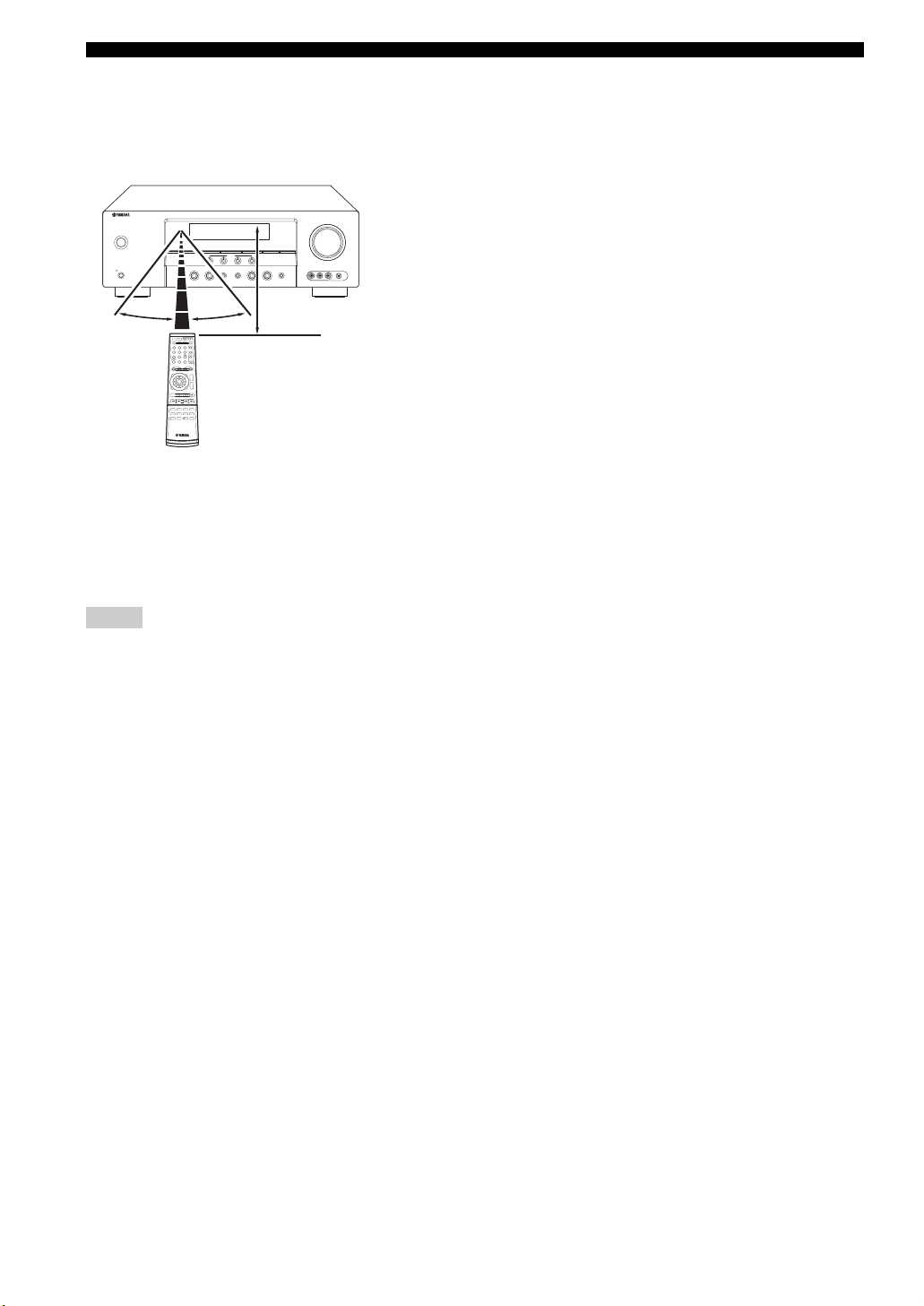
■ Using the remote control
The remote control transmits a directional infrared ray.
Be sure to aim the remote control directly at the remote
control sensor on this unit during operation.
VOLUME
STANDBY
/ON
EDIT
CATEGORY
SEARCH MODE
FM/AM
l
A/B/C/D/E
PRESET/TUNING
SPEAKERS
PHONES
A/B/OFF
SILENT CINEMA
SCENE
1234
TONE CONTROL
EFFECT
PRESET/TUNING/CH
NIGHTSTRAIGHT
DISPLAY
h
MEMORY
TUNING AUTO/MAN’L
l INPUT hl PROGRAM h
VIDEO AUX
VIDEO L AUDIO R PORTABLE
AUDIO SELECT
30º 30º
X
Infrared window
Approximately 6 m (20 ft)
Outputs infrared control signals. Aim this window at the
component you want to operate.
y
To set the remote control codes for other components, see
page 54.
Notes
• Do not spill water or other liquids on the remote control.
• Do not drop the remote control.
• Do not leave or store the remote control in the following types
of conditions:
– places of high humidity, such as near a bath
– places of high temperature, such as near a heater or stove
– places of extremely low temperatures
– dusty places
20 En
Loading…
-
Page 1: Yamaha HTR-6030
HTR-6030 AV R e c e i v e r O WNER’S MANU AL U 01EN_HTR-6030_U_cv-1.fm Pag e 1 Tuesday, December 19, 2006 11:00 AM[…]
-
Page 2: Yamaha HTR-6030
IMPORTANT SAFETY INSTRUCTIONS Caution-i En • Explanation of Graphical Symbols The lightning flash with arrowhead symbol, within an equilateral triangle, is in tended to alert you to the presence of uninsulated “dangerous voltage” within the product’ s enclosure t hat may be of sufficient magnitude to constitut e a risk of electric shock to […]
-
Page 3: Yamaha HTR-6030
Important safety instructions Caution-ii En EXAMPLE OF ANTENNA GROUNDING MAST GROUND CLAMP ANTENNA LEAD IN WIRE ANTENNA DISCHARGE UNIT (NEC SECTION 810–20) GROUNDING CONDUCTORS (NEC SECTION 810–21) GROUND CLAMPS POWER SERVICE GROUNDING ELECTRODE SYSTEM (NEC ART 250. PART H) ELECTRIC SERVICE EQUIPMENT NEC – NATIONAL ELECTRICAL CODE d) If the p[…]
-
Page 4: Yamaha HTR-6030
CAUTION: READ THIS BEFO RE OPERATING YOUR UNIT. Caution-iii En 1 T o assure the finest performan ce, please r ead this manual carefully . Keep it in a safe place for future refer ence. 2 Install this sound system in a well ventilated, cool, dry , clean place – away from direct sunlight, heat sources, vibration, dust, moisture, and/or cold. A llow[…]
-
Page 5: Yamaha HTR-6030
1 En PREP ARA T ION INTRODUCTION BAS I C OPERA TION AD V ANCED OPERA TION ADDITIONAL INFORMA TION APPENDIX English Featur es ….. ……… ………… ………. ………. ………… ……… 2 Getting st arted …………. ………. ………… ……… ………… 3 Quick star t guide ………………. ……… ………. ………[…]
-
Page 6: Yamaha HTR-6030
Features 2 En Built-in 5- channel power ampli fier ◆ Minimum RMS output po wer [U.S.A. and Canada models] (1 kHz, 0.9% THD, 8 Ω ) Front: 100 W + 100 W Center: 100 W Surround: 100 W + 100 W [Other models] (1 kHz, 0.9% THD, 6 Ω ) Front: 100 W + 100 W Center: 100 W Surround: 100 W + 100 W SCENE select function ◆ Preset SCENE templates for vari[…]
-
Page 7: Yamaha HTR-6030
Getting started 3 En INTRODUCTION English ■ Checki ng the supplied accessories Check that you recei ved all of the follow ing parts. The form of the supplied accesso rie s varies depending on the models. ■ V O L T A GE SELECTOR (Asia and General models only) Select the switch positi on (upper or lower) accor ding to your local v oltage using a […]
-
Page 8: Yamaha HTR-6030
Quick start guide 4 En The following steps describe the easiest way to enjoy D VD movie playback in your home theater . In these steps, you need the follo wing supplied accessories. ❏ Indoor FM antenna ❏ AM loop antenna The follow ing items are not included in the package of this unit. ❏ Speakers ❏ Fro nt speakers ………… ………….[…]
-
Page 9: Yamaha HTR-6030
Quick start guide 5 En INTRODUCTION English Place your speakers in the r oom and connect them to this unit. 1 Place your speaker s and subwoofer in the room. 2 Connect speaker cables to each speaker . Cables are col ored or shaped differently , perhaps with a stripe, groo ve or ridge. Connect the striped (groov ed, etc.) cable to the “+” (red) […]
-
Page 10: Yamaha HTR-6030
Quick start guide 6 En 1 Connect the digital coaxial audio cable to the digital coax ial audio outpu t jack of y our D VD play er and the DVD DI GIT AL INPUT CO AXIAL jack of t his unit. 2 Connect the video cable to the composite video output jack of your D VD player and the D VD VIDEO jack of th is unit. 3 Connect the video cable to the video inpu[…]
-
Page 11: Yamaha HTR-6030
Quick start guide 7 En INTRODUCTION English 4 Connect the FM an d AM antennas to this unit. See page 18 for the details. y The wire of the AM loop antenna does not hav e any polarity and you can connect either end of th e wire to AM or GND terminal. 5 Connect the p ower plug of this un it and other components into the AC wall outlet. Indoor FM ante[…]
-
Page 12: Yamaha HTR-6030
Quick start guide 8 En 1 T urn on the video monitor connected to this unit. 2 Press 1 ST ANDBY/ON on the fr ont panel. 3 Press F SCENE 1 . “D VD V ie wing” appears in the front panel display , and this unit autom atically optimize o wn status for the D VD playback. y The indicator on the selected SCENE button lights up while this unit is in the[…]
-
Page 13: Yamaha HTR-6030
Quick start guide 9 En INTRODUCTION English Case C: “I want to listen to a music program from the FM radio station… ” Press F SCENE 4 (or E SCENE 4 ) to select “Radio Listenin g”. • T o use the “Radio Listening” template, you must tune into the desired radio station in advance. See p ages 34 to 36 for tuning information. • T o ach[…]
-
Page 14: Yamaha HTR-6030
Connec tions 10 En 1 XM jack (U .S.A. and Canada models only) See page 37 for connection information. 2 COMPONENT VIDEO jacks See page 16 for connection information. 3 VIDEO jacks See pages 15 for conne ction information. 4 ANTENNA terminals See page 18 for connection information. 5 SPEAKERS terminals See page 12 for connection information. 6 DIGIT[…]
-
Page 15: Yamaha HTR-6030
11 En Connections PREP ARA T ION English The speaker layout belo w shows the speaker setting we re commend. Y ou can use it to enjoy CINEMA DSP a nd multi- channel audio sources. Front left and right speakers (FL and FR) The front speakers are used for the main source sound plus effect sounds. Place these speakers at an equal dis tance from the ide[…]
-
Page 16: Yamaha HTR-6030
12 En Connec tions Be sure to connect the left ch annel (L), right channel (R), “+” (red) and “–” (black) prope rly . If the connections are faulty , this unit cannot reproduce the input sources accurately . ■ Before connecting to the SPEAKERS terminal A speaker cord is actually a pair of insulated cables running side by side. Cables ar[…]
-
Page 17: Yamaha HTR-6030
13 En Connections PREP ARA T ION English ■ Connecting to the FR ONT A terminals 1 Loosen the knob. 2 Insert the bare end of the speaker wire into the hole on the terminal. 3 Tighten the knob to secure the wire . Connecting the banan a plug (except Eur ope , Korea and Asia models) The banana plug is a single- pole electrical connector widely used […]
-
Page 18: Yamaha HTR-6030
14 En Connec tions ■ Aud i o j a cks This unit has three types of audio jacks. Connection depends on the a vailability of audio jacks on your other components. A UDIO jacks For con ventional analog audio si gnals transmitted via left and right analog audio cables . Connect red plugs to the right jacks and white pl ugs to the left jacks. DIGIT AL […]
-
Page 19: Yamaha HTR-6030
15 En Connections PREP ARA T ION English Connect the video components as follo ws. y Y ou can also connect a video monitor , DVD p l ayer , digital TV , and cable TV to this unit using the COMPONENT VIDEO connection (see page 16 ). ■ Connecting a video monitor and a D VD playe r ■ Connecting a cab le TV/satellite tune r and a D VD record er Con[…]
-
Page 20: Yamaha HTR-6030
16 En Connec tions ■ Connecting to the COMPONENT VIDEO jac ks Y ou can enjoy high-quality pictu res by connecting your video monitor and video sour ce components to this unit using COMPONENT VIDEO connection. Be sure to connect your video source components in the same way you connect yo ur video monitor to this unit. For e xample, if you connect […]
-
Page 21: Yamaha HTR-6030
17 En Connections PREP ARA T ION English Connect the audio components as follo ws. ■ Connecting a CD pla yer and a CD recorder/MD recor der When you connect your CD player via analog and digit al connection, priority is giv e n to the signal input at the DIGIT AL INPUT jack. ■ Connecting to the MUL TI CH INPUT jac ks This unit is equipped with […]
-
Page 22: Yamaha HTR-6030
18 En Connec tions Both FM and AM indoor ante nnas are supplied with this unit. In general, these ante nnas should pr ovide suff icient signal strength. Connect ea ch antenna correctly to the designated terminals. • The AM loop antenna should be placed away from this unit. • A properly installed outdoor an tenna provides clearer reception than […]
-
Page 23: Yamaha HTR-6030
19 En Connections PREP ARA T ION English 1 Decoder indicator Lights up when any of the dec oders of this unit functions. 2 ENHANCER indicator Lights up when the Compressed Music Enhan cer mode is selected (see page 31). 3 VIRT UA L indicator Lights up when V irtual CINEMA DSP is active (see page 33). 4 SILENT CINEMA indicator Lights up when headpho[…]
-
Page 24: Yamaha HTR-6030
20 En Connec tions ■ Using the remote cont rol The remote c ontrol transmits a directiona l infrared ray . Be sure to aim the remote control directly at the remote control sensor on this unit during operation. X Infrared windo w Outputs infrared control signals. Aim this windo w at the component you want to operate. y T o set the remote control c[…]
-
Page 25: Yamaha HTR-6030
Basic setup 21 En PREP ARA T ION English The “B ASIC SETUP” feature is a useful way to set up your system quickly and with minimal ef fort. • Make sure you disconnect your headp hones from this unit. • If you wish to configur e this unit manually using more pr ecise adjustments, use the detaile d parameters in “SOUND MENU” (see page 45)[…]
-
Page 26: Yamaha HTR-6030
22 En Basic setup 7 Press G n to sele ct “SET” and then G l / h to select the desired setting. SET >CANCEL Choices: SET, CANCEL • Select “SET” to apply the settings you made. • Select “CANCE L” to cancel th e setup procedure without making any changes. y Y ou can also press P MENU to cancel the setup procedure. 8 Press G ENTER to[…]
-
Page 27: Yamaha HTR-6030
SELECTING THE SCENE TEMPLATES 23 En BAS I C OPERA TION English This unit is equipped with 13 preset SCENE templ ates for va rious situations of using this unit. As the initial factory setting, the f ollowing SCENE tem plates are assigned to each SCENE button: SCENE 1 : D VD V iewing SCENE 2 : Disc Listening SCENE 3 : TV V i ewing SCENE 4 : Radio Li[…]
-
Page 28: Yamaha HTR-6030
24 En Selecting the SCENE templates ■ Which SCENE template w ould you like to selec t? * T o enjoy XM Satellite Radio programs, you need to connect the XM M ini-T uner Dock (sold separ ate ly) to this un it (see pa ge 37). y Y ou can create your original SCE NE templates by editing the preset SCENE templates. See page 26 for details. Note Radio L[…]
-
Page 29: Yamaha HTR-6030
25 En Selecting the SCENE templates BAS I C OPERA TION English ■ Preset SCENE template descriptions SCENE template Features Input source Pl ayba ck m od e D VD Viewing (SCENE 1 as the default setting) Select thi s SCENE template whe n you play back gene ral conten ts on your D VD player . D VD STRAIGHT DV D M o v i e V i ew in g Select th is SCEN[…]
-
Page 30: Yamaha HTR-6030
26 En Selecting the SCENE templates Y ou can create your original SCENE templates for each SCENE button. Y ou can refer to the preset 13 SCENE templates to c reate the original SCENE templates. ■ Customizing the pres et SCENE template s Use this feature to customize the preset SCENE templates . 1 Press and hold the desired E SCENE button for 3 se[…]
-
Page 31: Yamaha HTR-6030
PLAYBACK 27 En BAS I C OPERA TION English 1 T urn on the video moni tor connected to this unit. 2 Press 9 SPEAKERS repeatedly to select the front speaker s you want to use. The respectiv e speaker indicators lights up in the front panel display . 3 Press D INPUT l / h repeatedly (or press one of the input se lector buttons ( C )) to select the desi[…]
-
Page 32: Yamaha HTR-6030
28 En Playback ■ Using y our headphones Connect a pair of head phones with a st ereo analog audio cable plug to the PHONES jack on the front panel. y When you select a soun d field program, SILENT CINEMA mode activ ates automatically (see page 33). • When you connect headphones, no signals ar e output at the speaker terminals. • All Dolby Dig[…]
-
Page 33: Yamaha HTR-6030
29 En Playback BAS I C OPERA TION English 2 Press G l / h to adjust the effect level while “NIGHT :CINEMA” or “NIGHT :MUSIC” is displa yed in the front panel disp lay . Choices: MIN, MID , MAX • Select “MIN” for minimu m compression. • Select “MID” for stand ard compression. • Select “MAX” for maximum comp ression. y “NI[…]
-
Page 34: Yamaha HTR-6030
30 En Playback ■ Displa ying the sign al informati on Y ou can display the format, sampling frequenc y , channel, bit rate and flag data of the current input signal. 1 Press D AMP and then press P MENU on the remote control. “B ASIC SETUP” appears in the front panel display . ; BASIC SETUP 2 Press G k / n repeatedly to select “SIGNAL INFO?[…]
-
Page 35: Yamaha HTR-6030
SOUND FIELD PROGRAMS 31 En BAS I C OPERA TION English This unit is equipped with a variety of precise digital decoders that allow you to en joy multi-channel playback from almost any stereo or multi-channel sound source. Press A PR OGRAM l / h (or press D AMP and then press I PROG l / h repeatedl y). The name of the selected s ound field program ap[…]
-
Page 36: Yamaha HTR-6030
32 En Sound field programs ■ Selecting decoder s f or 2-channel source s (surround decod e mode) Signals input from 2-channel s ources can also be played back on multi-channels. Press D AMP and then press J SUR. DECODE repeatedly to select a decoder . Y ou can select fro m the foll ow ing decoders depending on the type of source you are playing a[…]
-
Page 37: Yamaha HTR-6030
33 En Sound field programs BAS I C OPERA TION English ■ Using sound field pr ograms without surround speakers (Virtual CINEMA DSP) V irtual CINEMA DSP allo ws you to enjoy the CINEMA DSP programs without surround speake rs by creating virtual speakers. If you set “SUR. LR” to “ NONE” (see page 45), V irtual CINEMA DSP activ ates au tomati[…]
-
Page 38: Yamaha HTR-6030
FM/AM TUNING 34 En There are 2 tuning methods: automatic a nd manual. Automatic tuning is ef fectiv e when st ation signals are strong and there is no interference. If the signal from the station you want to select is weak, tune into it manually . Y ou can also use the automatic and ma nual preset tuning fe atures to store up to 40 stations. Automa[…]
-
Page 39: Yamaha HTR-6030
35 En FM/AM tuning BAS I C OPERA TION English Y ou can use the automatic pres et tuning feature to store FM stations with strong signals up to 40 (A1 to E8: 8 preset station numbers in ea ch of the 5 preset station groups) of those stations in order . Y ou can then recall an y preset station easily by sele cting the preset station number . 1 Press […]
-
Page 40: Yamaha HTR-6030
36 En FM/AM tuning Y ou can tune into an y desired station simply by selecting the preset station group and number under which it was stored. y When performing this oper ation w ith the remote control, press C TUNER to select “TUNE R” as the input source. 1 Press 4 A/B/C/D/E (or G A-E/C A T . l / h ) repeatedly to select the desired preset stat[…]
-
Page 41: Yamaha HTR-6030
XM SATELLITE RADIO TUNING 37 En BAS I C OPERA TION English XM Satellite Radio of fers an extraordinary v ariety of commercial-free music, plus the best in sports, ne ws, talk and entertainment. XM is br oadcast in superior digital audio from coast to coast. From rock to re ggae, from classical to hip hop, XM ha s something fo r every music fan. XM?[…]
-
Page 42: Yamaha HTR-6030
38 En XM Satellite Radio tuning Once you ha ve installed the XM Mini-T uner Dock, inserted the XM Mini-T uner, connected the XM Dock to your XM Ready ® home audio system, and installed the antenna, you are ready to subscribe and begin recei ving XM programming. There are three places to find your eight character XM Radio ID : on the XM Mini-T uner[…]
-
Page 43: Yamaha HTR-6030
39 En XM Satellite Radio tuning BAS I C OPERA TION English y When performing these operations with the remote control, press C XM to select “XM” as the input sour ce. ■ All Channel Sear ch mode 1 Press 2 SEARCH MODE (or P SRCH MODE ) repeatedly to select “ALL CH SEARCH”. 2 Press 5 PRESET/TUNING/CH l / h (or G PRESET/CH k / n ) repeatedly […]
-
Page 44: Yamaha HTR-6030
40 En XM Satellite Radio tuning Y ou can use this feature to store up to 40 XM Satellite Radio channels (A1 to E8: 8 preset channel numbers in each of the 5 preset channel groups). Y ou can then recall any preset channel easily b y selecting the preset channel group and number as describe d in “Preset Search mode” on page 39. 1 Search f or a ch[…]
-
Page 45: Yamaha HTR-6030
41 En XM Satellite Radio tuning BAS I C OPERA TION English Y ou can display the XM Satel lite Radio info rmation (such as channel number , channel na me, category , artist name , or song title) for the currently selected channel in the front panel display . If a status message or an error me ssage appears in the front panel display , see the “XM […]
-
Page 46: Yamaha HTR-6030
RECORDING 42 En Recording adjustments and ot her operations are performed from the reco rding components. Re fer to the operating instructions for those components. • When this unit is set to the standby mode, you cannot r ecord between other componen ts connected to this unit. • The settings of TONE CONTROL (see page 29) and V OLUME settings ,[…]
-
Page 47: Yamaha HTR-6030
Set menu 43 En AD V ANCED OPERA TION English Y ou can use the following parameters in set menu to adjust a var iety of system settings a nd customize the way this unit operates. Change the initial settings (indicated in bold unde r each parameter) to reflect the needs of you r listening en vironment. ■ Basic setup BASIC SETUP Use this feature to […]
-
Page 48: Yamaha HTR-6030
44 En Set menu Option menu 3 OPTION MENU Use this menu to manually adj ust the optional syst em parameters. The “XM RADIO SET ” parameter is only applicable to the U. S.A. and Canada mod els. ■ Signal information SIGNAL INFO Use this feature to check audio signal information (see page 30). Use the remote control to access an d adjust each par[…]
-
Page 49: Yamaha HTR-6030
45 En Set menu AD V ANCED OPERA TION English Use this menu to manually adjust any speaker settings or compensate for vide o signal processing delays when using LCD monitors or projectors. ■ Speaker setti ngs A)SPEAKER SET Use this feature to manually adjust any speaker settings. FRONT B speaker setting FRONT B Use this feature to sel ect the loca[…]
-
Page 50: Yamaha HTR-6030
46 En Set menu LFE/Bass out BASS OUT Use this feat ure to select th e speakers that output the LFE (low-frequenc y effect) and the low-frequenc y signals. Choices: SW FR, FRNT, BO TH y If you are not satisfied with the bass sounds from your speak ers, you can change these settings according to your preference. When a subw oofer is connected to this[…]
-
Page 51: Yamaha HTR-6030
47 En Set menu AD V ANCED OPERA TION English ■ Speaker dista nce C)SP DISTANCE Use this feature to manually adj ust the distance of each speaker and the delay applied to the respective channel. Ideally , each speaker shoul d be the same distance from th e main listening position. Ho weve r , this is not possible in most home situations. Thus, a c[…]
-
Page 52: Yamaha HTR-6030
48 En Set menu ■ A udio settings G)AUDIO SET Use this feat ure to adjust the overall audio settings of this unit. Mute type MUTE TYP. Use this feature to adjust ho w much the mute function reduces the output v olume (see page 28). Choices: FULL , –20dB • Select “FULL ” to completely mute all the audio output. • Select “–20dB” to r[…]
-
Page 53: Yamaha HTR-6030
49 En Set menu AD V ANCED OPERA TION English ■ Input rename B)INPUT REN AME Use this feature to change th e name of the input source that appears in the front panel display . The following is an e xample where “DVD” is renamed “My D VD”. 1 Press one of the input selector buttons ( C ) or A MUL TI CH IN to select the input source y ou want[…]
-
Page 54: Yamaha HTR-6030
50 En Set menu Use this menu t o adjust the optional system paramete rs. ■ Displa y settings A)DISPLAY SET Dimmer DIMMER Use this feat ure to adjust th e brightness of the front panel display . Control range: – 4 to 0 Control step: 1 • Press G l to mak e the front panel display d immer . • Press G h to make the front panel display brighter […]
-
Page 55: Yamaha HTR-6030
Remote control features 51 En AD V ANCED OPERA TION English In addition to controlling thi s unit, the remote control ca n also operate other audiovisua l components made b y Y amaha and other manufacturers. T o control your TV or other com ponents, you must set up the appr opriate remote control code for each input source (see page 54). ■ Contro[…]
-
Page 56: Yamaha HTR-6030
52 En Remote control features ■ Controlling this unit Press D AMP to control this unit. *1 These buttons alw ays control this unit. *2 These buttons control this unit only when D AMP is pressed. ■ Contro lling a TV Press C DTV/CBL to control y our TV . T o control your TV , you must set the appropriate remote control code for DTV/CBL (see page […]
-
Page 57: Yamaha HTR-6030
53 En Remote control features AD V ANCED OPERA TION English ■ Controlling other compone nts Press one of the input selector buttons ( C ) or to control other components. Y ou must set the appropriate remote control code for each input source in advance (see page 54). The follo wing table shows the function of each control b utton used to cont rol[…]
-
Page 58: Yamaha HTR-6030
54 En Remote control features Y ou can control other components b y setting the appropriate remote control code s. For a comple te list of av ailable remot e control codes, refer to “List of remote control codes” at the end of this manual. Remote control code default settings Y ou may not be able to operate your Y amaha component e ven if a Y a[…]
-
Page 59: Yamaha HTR-6030
Advanced setup 55 En AD V ANCED OPERA TION English This unit has additional menus that are displayed in the front panel display . The ad vanced setup menu offers additional operations to adjust and customize the way this unit operates. Chan ge the initial settings (indica ted in bold under each parameter) to re flect the needs of your listening en […]
-
Page 60: Yamaha HTR-6030
Troubleshooting 56 En Refer to the table below when this un it does not function properly . If the proble m you are experiencing is not listed below or if the instruction belo w does not help, turn of f this unit, disconnect the power cable, and cont act the n earest authorized Y amaha dealer or service center . ■ General T roubleshooting Problem[…]
-
Page 61: Yamaha HTR-6030
57 En Troubleshooting ADDITIONAL INFORMA TION English Prob lem Cause Remedy See page The sound su ddenly goes off. The protect ion circuit ry has been act iv ated because of a short circuit, etc. Check that the imped ance setti ng is corr ect. 13 Check that the speaker wi res are not t ouching eac h other and the n turn this unit back on . — The […]
-
Page 62: Yamaha HTR-6030
58 En Troubleshooting Problem Ca use Remedy See page Dolby Digital or DTS sources cannot be played. (Dolb y Digital or DTS indicator in the front panel display does not ligh t up.) The connecte d componen t is not set to output Dolby Dig ital or DTS digital signals. Make an appropriat e setting fol lowing the operating instruct ions for y our compo[…]
-
Page 63: Yamaha HTR-6030
59 En Troubleshooting ADDITIONAL INFORMA TION English ■ T uner ■ XM Satellite Radio (U.S.A. and Canada models only) If an operation takes longer than usual or an error occurs, one of the follo wing messages may appear in the front panel display . In this case, read the caus e and follow the co rresponding remedies. Prob lem Cause Remedy See pag[…]
-
Page 64: Yamaha HTR-6030
60 En Troubleshooting ■ Remote contr ol ■ Resetting the system Use this feature to reset all the parame ters of this unit to the initial f actory settings. 1 Press 1 ST ANDBY/ ON on the front panel to set this unit to the standb y mode . 2 Press and hold 0 TONE CONTR OL and then press 1 ST ANDBY/ON to turn on this unit. The advanced setup menu […]
-
Page 65: Yamaha HTR-6030
Glossary 61 En ADDITIONAL INFORMA TION English ■ A udio information Dolby Digital Dolby Digital is a digital surround sound system that gives you completely independent mu lti-channel audio. W ith 3 front channels (front L/R and center), and 2 surround stereo channels, Dolb y Digita l provides 5 full-range audio channels. W ith an additional chan[…]
-
Page 66: Yamaha HTR-6030
62 En Glossary Sampling frequency and number of quantized bits When digitizing an analog audio signal, the number of times the signal is sample d per second is called the sampling frequency , while the de gree of fineness when con verting the sound le vel into a numeric v alue is called the number of quantized b its. The range of rates that can be […]
-
Page 67: Yamaha HTR-6030
Specifications 63 En ADDITIONAL INFORMA TION English A U DIO SECTION • Minimum RMS Outpu t Power for Fron t, Center , Surround [U.S.A. and C anada models ] 1 kHz, 0.9% THD, 8 Ω ……………. ……………… ……………… 100 W [Other models] 1 kHz, 0.9% THD, 6 Ω ……………. ……………… ……………… 100 W • Ma xi[…]
-
Page 68: Yamaha HTR-6030
INDEX 64 En ■ Numerics 1 SOUND MENU ……….. …………. …….. 43 2 INPUT MENU …. ………… ………… 43 , 48 2ch Stereo ……………….. …………. ……….. 31 3 OPTION MENU ……. …………. ….. 44 , 50 5ch Stereo ……………….. …………. ……….. 31 ■ A A)DISPLAY SET …….. …………. …….[…]
-
Page 69: Yamaha HTR-6030
Index 65 En ADDITIONAL INFORMA TION English MULTI CH INPUT j acks ……… ……….. 1 0 Multi channel input setup ………… …….. 49 Multi-channel sources and sound field programs with headphones …… …….. 33 Multi-information display ……………. …. 19 Music Disc Listening ……………. ……….. 2 5 Music Enh. 2ch … .[…]
-
Page 70: Yamaha HTR-6030
i ■ Fro nt panel SPEAKERS PHONES SILENT CINEMA STANDBY /ON A/B/OFF l PRESET/TUNING/CH h CATEGOR Y A/B/C/D/E FM/AM EDIT SEARCH MODE PRESET/TUNING MEMORY DISPLAY TUNING AUTO/MAN’L AUDIO SELECT NIGHT STRAIGHT EFFECT TONE CONTROL l INPUT h l PROGRAM h VOLUME SCENE 123 4 VIDEO L AUDIO R POR TABLE VIDEO AUX 17 6 34 5 8 90 D A C E F B 2[…]
-
Page 71: Yamaha HTR-6030
ii APPENDIX ■ Remote contr ol REC SUR.DECODE NIGHT STRAIGHT ENHANCER l PROG h TV MUTE TV INPUT TV VOL TV CH POWER AMP ST ANDBY POWER AUDIO SEL SLEEP MUTE MUL TI CH IN POWER 8 10 7 0 9 6 5 4 3 2 1 ENT . DVD V- AU X X M DTV/CBL DVR CD MD/CD-R TUNER MENU SRCH MODE VOLUME TITLE ENTER BAND LEVEL DISPLAY RETURN XM MEMORY AV TV SCENE 4 3 2 1 Q J N I H A[…]
-
Page 72: Yamaha HTR-6030
iii List of remote control codes TV A CER 009 3 A CM E 0207 A CURA 020 8 AD A 0255 ADC 0206 ADMIRAL 0058, 0205, 0206, 0210, 0211 AD YSON 0200, 0207 A GA SHI 0200 A GA ZI 0206 A GB 020 4 AIKO 0127, 0200, 0207, 0208 AIW A 002 8, 0139, 0229, 0237 AKAI 0059, 0065, 0127, 0129, 0130, 0200, 0204, 0208, 0209, 0213, 0217, 0218, 0255 AKIBA 0209, 0218 AKURA 0[…]
-
Page 73: Yamaha HTR-6030
iv APPENDIX INNO HIT 0201, 0204, 0207, 0208, 0209, 0213, 0217, 0218 INNO V A TION 0206 , 0208 INTERBUY 0208, 0214 INTERFUNK 0205, 0211, 0213, 0214, 0216, 0217 INTERNA TIONAL 0200 INTER VISION 0206, 0207, 0218 IRRADIO 0201, 020 8, 0209, 0213, 0217, 0218 ISUKAI 0209, 0218 ITC 0207, 021 5 ITS 0200, 0209, 0213, 0218 ITT 0129, 0208, 0211 ITV 0208 , 0217[…]
-
Page 74: Yamaha HTR-6030
v SEARS 0057, 0060, 0061, 0064 SEG 0200, 0206, 0207, 0214, 0215, 0217 SEI 0204 SEI-SINUD YNE 0204, 0205, 0211 SELECO 0210, 0211, 0215 SENCORA 0208 SENTRA 0218 SERINO 0200 SHARP 0009, 0010, 0011, 0060, 0061, 0066, 0070, 0087, 0111, 0143, 0145, 0167, 0168, 0169, 0198, 0204, 0224, 0247, 0248, 0249 SHOGUN 0060 SIAREM 0204, 0205, 0 215 SICA T EL 0212 SI[…]
-
Page 75: Yamaha HTR-6030
vi APPENDIX EMERSON 1003, 1004, 1005, 1012, 1013 ETZUKO 1050 FERGUSON 1043 FIDELITY 1042 FINLANDIA 1046, 104 7, 1049 FINLUX 1042, 1043, 1046, 1047, 1049 FIRST LINE 1044, 1045, 1049, 1050 FISHER 1001, 1047 FLINT 1044 FORMENTI/PHOENIX 1046 FUJI 1004 FUJITSU 1042 FUNAI 1005, 104 2 GALAXY 1042 GARRARD 1005 GBC 1050 GE 1002 , 1004, 1009, 1014, 1030 GEC […]
-
Page 76: Yamaha HTR-6030
YAMAHA ELECTRONICS CORPORATION, USA 6660 ORANGETHO RPE AVE., BUENA PARK, CALIF. 90 620, U.S.A. YAMAHA CANADA MUSIC LTD. 135 MILNER AVE., SCAR BOROUGH, ONTARIO M1S 3R1, CANADA YAMAHA ELECTRONIK EUROPA G.m.b.H. SIEMENSSTR. 22-34, 25462 RE LLINGEN BEI HAMBURG, GERMANY YAMAHA ELECTRONIQUE FRANCE S.A. RUE AMBROISE CROIZA T BP70 CROISSY-BEAUB OURG 77312 […]
-
Page 77: Yamaha HTR-6030
The circled numbers and alphabets corre spond to those in the Owner’ s Manual. ■ Front panel HTR-6030 U SPEAKERS PHONES SILENT CINEMA ST ANDBY /ON A/B/OFF l PRESET/TUNING/CH h CA TEGORY A/B/C/D/E FM/AM EDIT SEARCH MODE PRESET/TUNING MEMORY DISPLAY TUNING AUT O/MAN’L AUDIO SELECT NIGHT STRAIGHT EFFECT TONE CONTROL l INPUT h l PROGRAM h VOLU[…]
-
Page 78: Yamaha HTR-6030
■ Remote contr ol REC SUR.DECODE NIGHT STRAIGHT ENHANCER l PROG h TV MUTE TV INPUT TV VOL TV CH PO WER AMP ST ANDBY PO WER A UDIO SEL SLEEP MUTE MUL TI CH IN PO WER 8 10 7 0 9 6 5 4 3 2 1 ENT . DVD V- A U X X M DTV/CBL DVR CD MD/CD-R TUNER MENU SRCH MODE VOLUME TITLE ENTER BAND LEVEL DISPLA Y RETURN XM MEMORY AV TV SCENE 4 3 2 1 Q J N I H A O T U[…]