
Найди любой мануал:
Например: Sony VGN-FW460J/T
Вы можете бесплатно скачать Руководство по эксплуатации для Yamaha RDX-E700.
Также вы сможете прочесть онлайн этот документ без скачивания.
Скачать Руководство по эксплуатации для Yamaha RDX-E700
Тип файла
PDF
Размер
1.27 Mb
Кол-во страниц
57
Просмотров
11070
Читать онлайн Руководство по эксплуатации для Yamaha RDX-E700 (Страница 1)

Другие DVD-плееры Yamaha RDX-E700
Топ Yamaha DVD-плееры
Ранее вы смотрели
Эта страница полезна для вас? Поделитесь ссылкой:

G
DVD RECEIVER
AMPLI-TUNER DVD
OWNER S MANUAL
MODE D EMPLOI
BEDIENUNGSANLEITUNG
BRUKSANVISNING
MANUALE DI ISTRUZIONI
MANUAL DE INSTRUCCIONES
GEBRUIKSAANWIJZING

CAUTION: READ THIS BEFORE OPERATING YOUR UNIT.
1 To assure the finest performance, please read this manual
carefully. Keep it in a safe place for future reference.
2 Install this sound system in a well ventilated, cool, dry, clean
place with at least 10 cm on the top, 10 cm on the left and right,
and 10 cm at the back of RDX-E700 — away from direct
sunlight, heat sources, vibration, dust, moisture, and/or cold.
3 Locate this unit away from other electrical appliances, motors, or
transformers to avoid humming sounds.
4 Do not expose this unit to sudden temperature changes from cold
to hot, and do not locate this unit in an environment with high
humidity (i.e. a room with a humidifier) to prevent condensation
inside this unit, which may cause an electrical shock, fire,
damage to this unit, and/or personal injury.
5 Avoid installing this unit where foreign object may fall onto this
unit and/or this unit may be exposed to liquid dripping or
splashing. On the top of this unit, do not place:
– Other components, as they may cause damage and/or
discoloration on the surface of this unit.
– Burning objects (i.e. candles), as they may cause fire, damage
to this unit, and/or personal injury.
– Containers with liquid in them, as they may fall and liquid
may cause electrical shock to the user and/or damage to this
unit.
6 Do not cover this unit with a newspaper, tablecloth, curtain, etc.
in order not to obstruct heat radiation. If the temperature inside
this unit rises, it may cause fire, damage to this unit, and/or
personal injury.
7 Do not plug in this unit to a wall outlet until all connections are
complete.
8 Do not operate this unit upside-down. It may overheat, possibly
causing damage.
9 Do not use force on switches, knobs and/or cords.
10 When disconnecting the power cable from the wall outlet, grasp
the plug; do not pull the cable.
11 Do not clean this unit with chemical solvents; this might damage
the finish. Use a clean, dry cloth.
12 Only voltage specified on this unit must be used. Using this unit
with a higher voltage than specified is dangerous and may cause
fire, damage to this unit, and/or personal injury. YAMAHA will
not be held responsible for any damage resulting from use of this
unit with a voltage other than specified.
13 To prevent damage by lightning, keep the power cord and outdoor
antennas disconnected from a wall outlet or the unit during a
lightning storm.
14 Do not attempt to modify or fix this unit. Contact qualified
YAMAHA service personnel when any service is needed.
The cabinet should never be opened for any reasons.
15 When not planning to use this unit for long periods of time (i.e.
vacation), disconnect the AC power plug from the wall outlet.
16 Be sure to read the “TROUBLESHOOTING” section on
common operating errors before concluding that this unit is
faulty.
17 Before moving this unit, press STANDBY/ON to set this unit in
standby mode, and disconnect the AC power plug from the wall
outlet.
18 Condensation will form when the surrounding temperature
changes suddenly. Disconnect the power cable from the outlet,
then leave the unit alone.
19 When using the unit for a long time, the unit may become warm.
Turn the power off, then leave the unit alone for cooling.
This unit is not disconnected from the AC power source as
long as it is connected to the wall outlet, even if this unit itself
is turned off. This state is called the standby mode. In this
state, this unit is designed to consume a very small quantity of
power.
FOR CANADIAN CUSTOMERS
To prevent electric shock, match wide blade of plug to wide
slot and fully insert.
This Class B digital apparatus complies with Canadian
ICES-003.
DANGER
When this unit is plugged to the wall outlet, do not place your
eyes close to the opening of the disc tray and other openings to
look into inside.
The laser component in this product is capable of emitting
radiation exceeding the limit for Class 1.
WARNING
TO REDUCE THE RISK OF FIRE OR ELECTRIC SHOCK,
DO NOT EXPOSE THIS APPLIANCE TO RAIN OR
MOISTURE.
■ For U.K. customers
If the socket outlets in the home are not suitable for the plug
supplied with this appliance, it should be cut off and an
appropriate 3 pin plug fitted. For details, refer to the instructions
described below.
Note
The plug severed from the mains lead must be destroyed, as a
plug with bared flexible cord is hazardous if engaged in a live
socket outlet.
■ Special Instructions for U.K. Model
IMPORTANT
THE WIRES IN MAINS LEAD ARE COLOURED IN
ACCORDANCE WITH THE FOLLOWING CODE:
Blue: NEUTRAL
Brown: LIVE
As the colours of the wires in the mains lead of this apparatus may not correspond with the coloured markings
identifying the terminals in your plug, proceed as follows:
The wire which is coloured BLUE must be connected to
the terminal which is marked with the letter N or coloured
BLACK. The wire which is coloured BROWN must be
connected to the terminal which is marked with the letter L
or coloured RED.
Making sure that neither core is connected to the earth
terminal of the three pin plug.
i

CONTENTS
INTRODUCTION
FEATURES……………………………………………………. 2
About this manual……………………………………………… 2
SUPPLIED ACCESSORIES …………………………… 2
CONTROLS AND FUNCTIONS ……………………. 3
Front panel ……………………………………………………….. 3
Display…………………………………………………………….. 4
Remote control………………………………………………….. 5
PREPARATION
CONNECTING SPEAKERS ………………………….. 7
Connecting speakers ………………………………………….. 8
Connecting a subwoofer …………………………………….. 8
CONNECTING A TV …………………………………….. 9
CONNECTING ANTENNAS………………………… 10
Connecting the AM loop antenna ………………………. 10
Connecting the FM antenna………………………………. 10
CONNECTING EXTERNAL
COMPONENTS ……………………………………….. 11
Connecting a CD recorder or MD recorder …………. 11
Connecting the Power Cables……………………………. 12
INSTALLING BATTERIES IN THE REMOTE
CONTROL……………………………………………….. 13
USING THE REMOTE CONTROL……………… 13
BASIC OPERATION
TURNING THE POWER
TO ON/STANDBY ……………………………………. 14
SELECTING AN INPUT SOURCE………………. 14
ADJUSTING THE VOLUME LEVEL………….. 15
MUTING THE SOUND (MUTE) ………………….. 15
ADJUSTING THE CLOCK ………………………….. 16
SETTING THE TIMER ……………………………….. 16
SETTING THE SLEEP TIMER……………………. 17
CHANGING THE BRIGHTNESS OF THE
DISPLAY………………………………………………….. 18
CHANGING DVD SETTING ON THE TV
(OSD MENU) ……………………………………………. 19
Operating the OSD menu………………………………….. 19
OSD guide ……………………………………………………… 20
SUPPORTED DISC TYPES …………………………. 21
BASIC PLAYBACK OPERATIONS …………….. 22
USEFUL PLAYBACK OPERATIONS …………. 23
Customizing playback order (Program Play) ………. 23
Playing back randomly
(Random Play)…………………………………………….. 24
Playing back repeatedly
(Repeat Play) ………………………………………………. 25
Operating disc menus (DVD menu/Video CD
Playback Control)………………………………………… 27
SELECTING AUDIO, SUBTITLE
AND ANGLE …………………………………………… 28
Selecting Audio and Subtitle Languages…………….. 28
Selecting a Viewing Angle ……………………………….. 28
ZOOMING IMAGES ……………………………………29
USING GUI……………………………………………………30
ENJOYING HIGH-QUALITY VIDEO
(NTSC/PROGRESSIVE SCAN)………………….31
ENJOYING MULTIMEDIA FILES
ON DISCS ………………………………………………….32
TUNING RADIO STATIONS ………………………..33
Tuning radio stations automatically
(Auto Tuning)……………………………………………… 33
Tuning radio stations manually (Manual Tuning)… 33
Selecting preset radio stations (Preset Tuning) ……. 34
Receiving FM Radio Data System stations
(U.K. and Europe models only)……………………… 34
PRESETTING RADIO STATIONS ……………….36
Presetting radio stations automatically
(Auto Preset)……………………………………………….. 36
Presetting radio stations manually
(Manual Preset) …………………………………………… 36
Editing the name of preset radio stations…………….. 37
ADVANCED OPERATION
PLAYING BACK EXTERNAL SOURCES…….38
TV playback …………………………………………………… 38
Other component playback ……………………………….. 38
RECORDING SOURCES WITH EXTERNAL
COMPONENTS …………………………………………39
Recording audio sources with the DVD receiver …. 39
ADJUSTING SOUNDS ………………………………….40
Adjusting Sound Settings …………………………………. 40
Night listening mode ……………………………………….. 41
CONTROLLING EXTERNAL
COMPONENTS …………………………………………42
Setting remote control codes …………………………….. 42
Available operations ………………………………………… 43
ADDITIONAL INFORMATION
TROUBLESHOOTING …………………………………44
General…………………………………………………………… 44
Remote control ……………………………………………….. 45
Disc playback …………………………………………………. 46
Radio reception……………………………………………….. 47
ADDITIONAL INFORMATION ……………………48
Disc Information……………………………………………… 48
Handling a disc ……………………………………………….. 49
GLOSSARY…………………………………………………..50
Audio formats …………………………………………………. 50
Audio information …………………………………………… 50
Video signal information ………………………………….. 51
Copyright and logo marks ………………………………… 51
SPECIFICATIONS………………………………………..52
PREPARATIONINTRODUCTION
OPERATION
BASIC
OPERATION
ADVANCED
INFORMATION
ADDITIONAL
English
1
FEATURES
FEATURES
• Plays DVDs, Video CDs, Audio CDs, MP3 CDs,
WMA CDs, DivX CDs and JPEG CDs.
• Easy operation with the MULTI JOG
• Full function remote control
• On Screen Display (OSD) Menu
• DIGITAL OPTICAL OUT jack
About this manual
• In this manual, operations that can be performed using either the DVD receiver or its remote control are explained using the remote
control.
• Remote control descriptions and illustrations in this manual are based on the U.K. and Europe models unless otherwise specified.
• y indicates a tip for your operation.
• Notes contain important information about safety and operating instructions.
• This manual is printed prior to production. Design and specifications are subject to change in part as a result of improvements, etc. In
case of differences between the manual and the product, the product has priority.
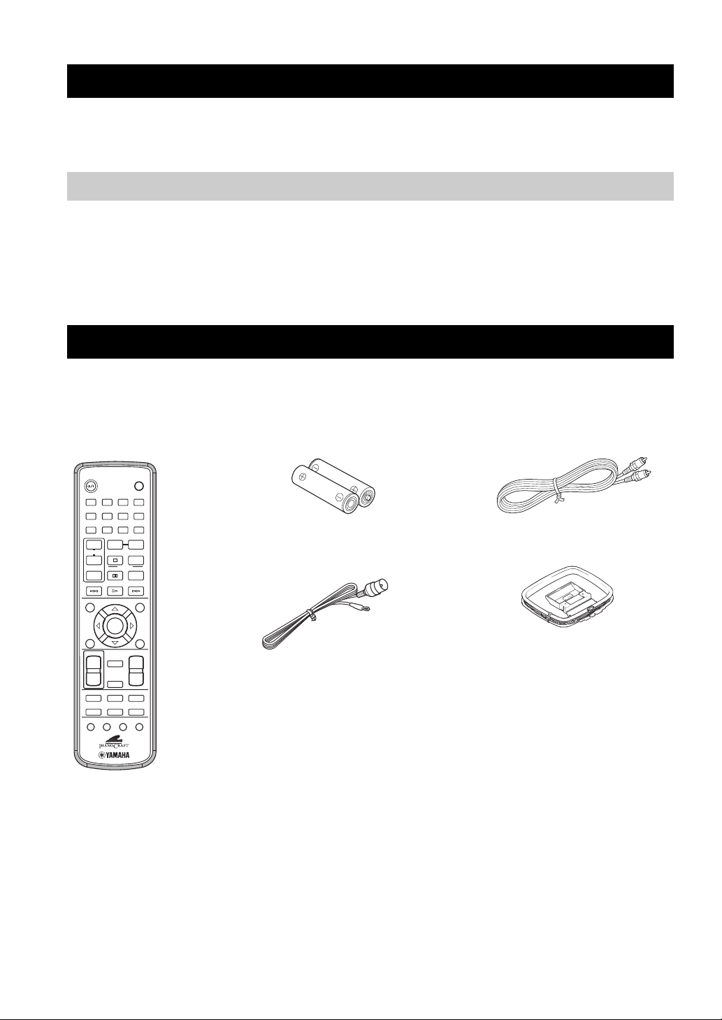
SUPPLIED ACCESSORIES
This product includes the following accessories. Before connecting speakers or a TV to this product, make sure you received all of the
following parts.
Remote
control
STANDBY/ON
1234
5678
DIMMER
90
REPEAT
+
TV CH
–
PTY SEEK
MODE START
TV INPUT
uPRESETPRESET
d
POWER
TV
SLEEP
A-B
FREQ/TEXT
PROG
RANDOM
MENUGUI
Batteries (x2)
(AA, R06, UM-3)
Indoor FM antenna
Video pin
cable
AM loop antenna
ENTER
VOLUME
MUTE
NIGHT
DVD/CD
TV
TUNER
AUX
ANGLE ZOOM AUDIO
+
–
TOP MENU
/
RETURN
SET UP
SUBTITLE
TV VOL
DIRECT
+
–
EQ
2
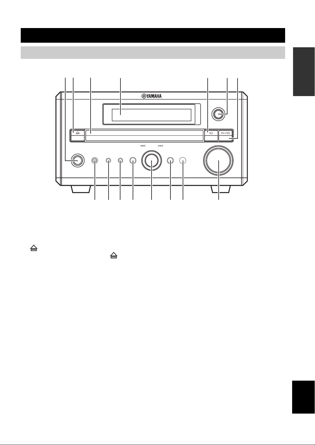
CONTROLS AND FUNCTIONS
Front panel
12 3 4 6 75
STANDBY/ON
PHONES TIMER
890A B CD E
1 STANDBY/ON
Turns this unit on. Press this button again to set the unit to
the standby mode (page 14).
DISPLAY SOUND MODE
INPUT
MULTI JOG
PUSH-ENTER
VOLUME
9 TIMER
Sets the DVD receiver to the timer play mode or sleep
mode.
INTRODUCTION
2
Opens and closes the disc tray. Pressing during
standby mode turns on the DVD receiver and sets the input
source to DVD/CD.
3 Disc tray
Holds a disc to be played.
4 Display
Displays playback information or settings (page 4).
5 s
Stops disc playback.
6 INPUT
Selects an input source.
7 h/e
Starts and pauses disc playback.
8 PHONES jack
Connects headphones.
0 DISPLAY
Displays the status information such as the elapsed time of
current track/chapter.
A SOUND
Switches the sound settings to be adjusted.
B MULTI JOG
Adjusts various settings and the frequency when tuning
radio station. You can also skip chapters or tracks when
the input source is set to DVD/CD.
C MODE
Supports MULTI JOG and enables various operations.
D Remote control sensor
Receives signals from the remote control.
E VOLUME
Adjusts the volume level.
English
3

CONTROLS AND FUNCTIONS
Display
123 45678
RNDM
A-B
PROG
SF
TITLE
TRK
CHAP
1 Playback mode indicator
Displays the icon for the selected playback mode.
2 Pause icon
Lights up when disc playback is paused.
3 Playback icon
Lights up during disc playback.
4 MUTE
Lights up when the mute function is activated.
5 PROGRESSIVE
Lights up when the progressive scan function is activated.
6 SLEEP
Lights up when the sleep timer function is activated.
PROGRESSIVE
MUTE ST MEMORY
SLEEP
7
Lights up when the timer play function is activated.
8
Lights up when receiving a strong radio signal when the
input source is set to AM or FM.
9 Display mode indicator
Lights up depending on the disc type.
0 ST
Lights up when receiving a strong FM radio signal in the
FM stereo mode.
A MEMORY
Lights up or blinks when presetting an FM/AM radio
station.
B Display
Displays various information such as a title, chapter or
track number, or elapsed playing time.
4
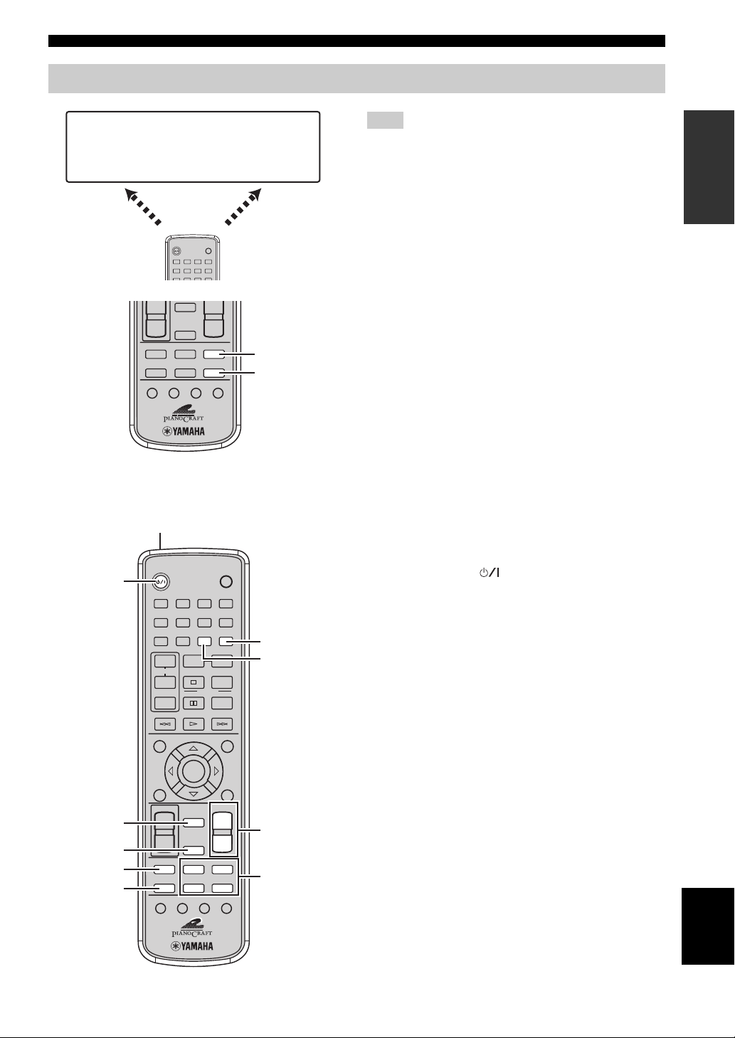
Remote control
CONTROLS AND FUNCTIONS
DVD/CD
• Playback
• Subtitle and
audio language
selection, etc.
DVD/CD mode
STANDBY/ON
1234
5678
DIMMER
+
NIGHT
–
TV
EQ
AUX
SUBTITLE
ANGLE ZOOM AUDIO
■ Common functions
1
STANDBY/ON
2
1234
5678
DIMMER
90
REPEAT
+
TV CH
–
MODE START
TV INPUT
d
ENTER
SET UP
TV VOL
MUTE
3
4
5
6
+
–
EQ
SUBTITLE
NIGHT
TV
AUXDIRECT
ANGLE ZOOM AUDIO
POWER
TV
SLEEP
DVD/CD
TUNERDIRECT
PTY SEEK
+
–
POWER
SLEEP
A-B
FREQ/TEXT
PROG
RANDOM
PRESETPRESET
u
MENUGUI
VOLUME
+
–
DVD/CD
TUNER
FM/AM
• Radio station
tuning
• Radio station
preset, etc.
TUNER
mode
DVD/CD
TUNER
TV
7
8
TOP MENU
/
RETURN
9
0
Note
Remote control descriptions and illustrations in this manual are
based on the U.K. and Europe models unless otherwise specified.
The DVD receiver has two main operation modes. Before
operating functions in each mode, you need to select a
mode to change the remote control button assignments.
To switch the operation mode
• DVD/CD mode: Press DVD/CD.
• TUNER mode: Press TUNER. For details on tuner
operations, refer to “TUNING RADIO STATIONS”
(page 33).
y
You can also operate the TV and other components connected to
the DVD receiver using the remote control. For details, refer to
“CONTROLLING EXTERNAL COMPONENTS” (page 42).
Operations common to all modes
1 Infrared signal transmitter
Sends signals to the DVD receiver.
2 STANDBY/ON ( )
Turn the DVD receiver on, or set it to the standby mode
(page 14).
3 MUTE
Turns off the volume. Press again to resume the volume.
4 NIGHT
Switches the night listening mode on or off (page 41).
5 EQ
Switches the EQ MODE (page 40).
6 DIRECT
Switches the DIRECT mode on or off.
7 SLEEP
Sets the sleep timer (page 17).
8 DIMMER
Changes the brightness of the display (page 18).
9 VOLUME +/–
Adjusts the overall volume level.
0 Input selection buttons
Selects the input source of the DVD receiver (page 14).
INTRODUCTION
English
5
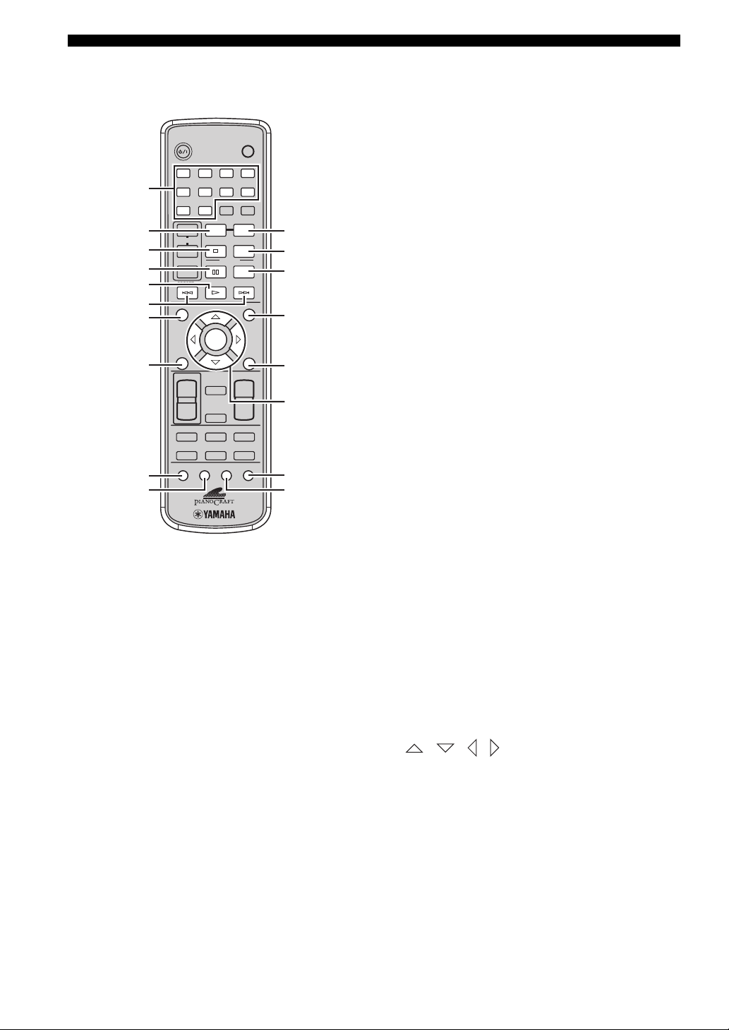
CONTROLS AND FUNCTIONS
■ DVD/CD mode Operations available only in DVD/CD mode
1 Number buttons (1 to 9, 0)
Press these buttons to enter numbers.
2 REPEAT
Enables the Repeat Play mode (page 25).
3 s
Stops disc playback.
4 e
Pauses disc playback.
5 h
Starts disc playback.
6 b, a
Skips to the start of the current chapter/track or next
chapter/track.
7 GUI
Displays the status information such as the elapsed time of
current track/chapter on the TV screen.
8 SET UP
Displays the OSD menu on the TV screen (page 19).
9 SUBTITLE
Selects subtitle language (page 28).
0 ANGLE
Selects a viewing angle (page 28).
1
2
3
4
5
6
7
8
9
0
STANDBY/ON
1234
5678
DIMMER
90
REPEAT
+
TV CH
–
PTY SEEK
MODE START
TV INPUT
SET UP
TV VOL
+
–
EQ
SUBTITLE
u
d
ENTER
VOLUME
MUTE
NIGHT
TV
AUXDIRECT
ANGLE ZOOM AUDIO
POWER
TV
SLEEP
A-B
FREQ/TEXT
PROG
RANDOM
PRESETPRESET
MENUGUI
TOP MENU
/
RETURN
+
–
DVD/CD
TUNER
A
B
C
D
E
F
G
H
A A-B
Enables the A-B Repeat mode (page 26).
B PROG
Enables the Program Play mode (page 23).
C RANDOM
Enables the Random Play mode (page 24).
D MENU
Displays the DVD menu on the TV screen (page 27).
E TOP MENU/RETURN
Returns the DVD menu to the previous screen (page 27).
F / / / / ENTER
Operates the OSD menu (page 19).
G AUDIO
Selects audio language (page 28).
H ZOOM
Zooms in a specified part of picture (page 29).
6
CONNECTING SPEAKERS
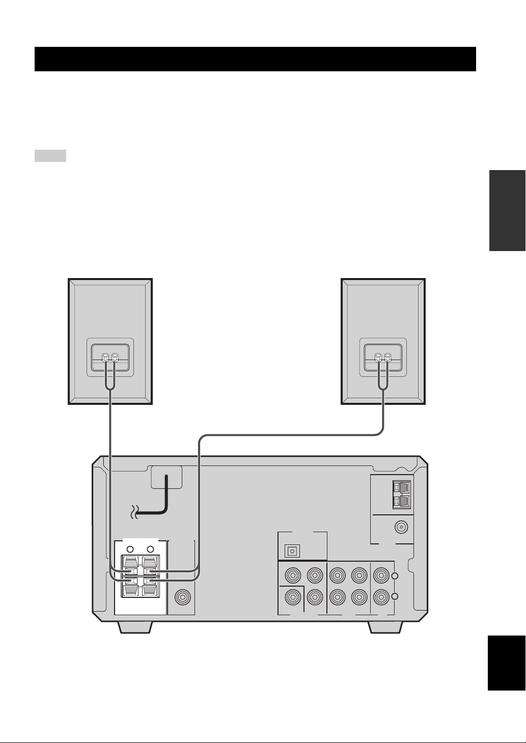
CONNECTING SPEAKERS
Follow the procedure below to connect speakers to the DVD receiver. Here, the connection example uses the YAMAHA
NX-E700 (consisting of two speakers) and its supplied cables. For information on your speakers, refer to the owner’s
manual for the speakers.
y
You can also use commercially available speakers (see page 8).
Notes
• Do not connect the power cable of the DVD receiver until all cable connections are completed.
• Be sure to connect the left channel (L), right channel (R), “+” (red) and “–” (black) properly. If the connections are faulty, no sound
will be heard from the speakers, and if the polarity of the speaker connections is incorrect, the sound will be unnatural and lack bass.
• Do not let the bare speaker wires touch each other or do not let them touch any metal part of this unit. This could damage the DVD
receiver and/or the speakers.
• Use speakers with the specified impedance shown on the rear panel of this unit.
• Use magnetically shielded speakers. If this type of speakers still creates the interference with the monitor, place the speakers away
from the monitor.
PREPARATION
R speaker
Speaker cable
MAINS
SPEAKERS
RL
6Ω MIN. /SPEAKER
SUB WOOFER
OUT
Speaker cable
DIGITAL
OPTICAL
OUT
Y
COMPONENT
VIDEO
P
B
PR
L speaker
FM ANT
75
IN INOUT
AUXVIDEO OUT TV
DVD receiver
AM
ANT
GND
Ω UNBAL.
TUNER
L
R
English
7
CONNECTING SPEAKERS
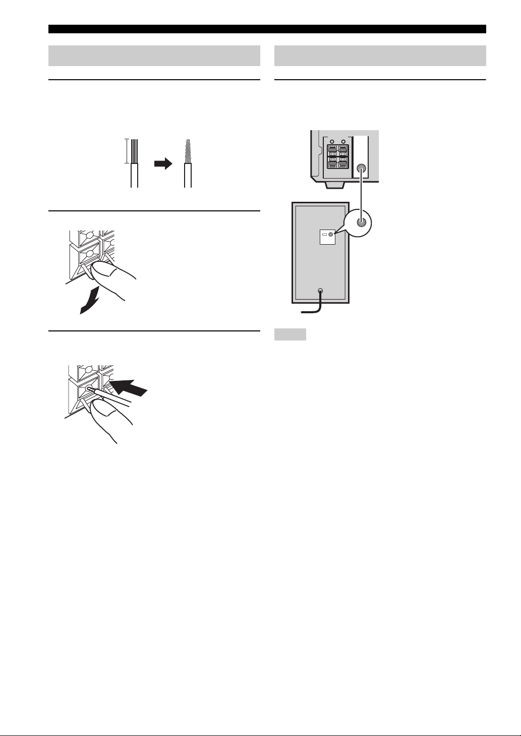
Connecting speakers
1 Remove approximately 10 mm (3/8 in) of
insulation from the end of each speaker
cable and twist the exposed wires of the
cable together to prevent short circuits.
10 mm (3/8 in)
2 Press and hold the lever.
Red: positive (+)
Black: negative (–)
3 Insert one bare wire. By releasing the lever,
the lever is replaced.
Connecting a subwoofer
Connect the SUBWOOFER OUT jack on the DVD
receiver to the INPUT jack on the subwoofer
using the subwoofer cable.
SPEAKERS
SUB WOOFER
OUT
RL
6Ω MIN. /SPEAKER
Subwoofer cable
INPUT
INPUT
Subwoofer
Notes
• Do not connect the power cable of the DVD receiver or
subwoofer until all cable connections are completed.
• The low frequency range of the downmixed sound is output at
the SUBWOOFER OUT jack.
Red: positive (+)
Black: negative (–)
■ Notes on the speaker cord
A speaker cord is actually a pair of insulated cables
running side by side. One cable is colored or shaped
differently, perhaps with a stripe, groove or ridge. Connect
the striped (grooved, etc.) cable to the “+” (red) terminals
on the DVD receiver and your speaker. Connect the plain
cable to the “–” (black) terminals on the DVD receiver
and your speaker.
8
CONNECTING A TV
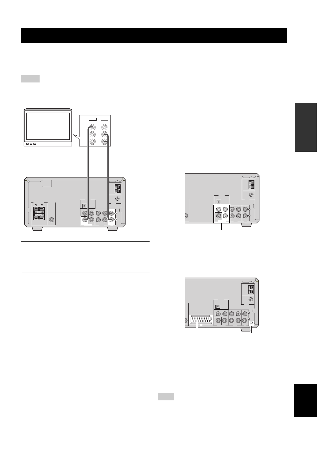
CONNECTING A TV
Follow the procedure below to connect your TV to the DVD receiver using the supplied video pin cable and audio cables
(sold separately). Also, you can enjoy high-quality pictures with a component video connection or a scart connection
(U.K. and Europe models only). For information about your TV, refer to the supplied manual.
Notes
• Do not connect the power cable of the DVD receiver until all cable connections are completed.
• Turn off the TV before connecting it to the DVD receiver.
OUT
IN
VIDEO
L
AUDIO
R
TV
MAINS
SPEAKERS
RL
6Ω MIN. /SPEAKER
SUB WOOFER
OUT
Video pin
cable
(supplied)
DIGITAL
OPTICAL
OUT
Y
COMPONENT
VIDEO
P
PR
B
IN INOUT
AUXVIDEO OUT TV
Audio cable
(sold separately)
AM
ANT
GND
FM ANT
Ω UNBAL.
75
TUNER
L
R
1 Connect the VIDEO jack on the DVD receiver
to the video input jack on your TV using the
supplied video pin cable.
2 To output sound from the speakers
connected to the DVD receiver, connect the
TV IN jacks on the DVD receiver to the audio
output jacks on your TV using an audio pin
cable (sold separately).
■ Other connection methods
To make a component video connection or a scart
connection (U.K. and Europe models only), a
corresponding cable is required.
Component video connection
Connect the VIDEO OUT COMPONENT jacks on the
DVD receiver to the component video input jacks on your
TV using a commercially available component video
cable.
AM
ANT
GND
P
PR
P
B
PR
B
IN INOUT
AUXVIDEO OUT TV
IN INOUT
AUXVIDEO OUT TV
FM ANT
Ω UNBAL.
75
TUNER
L
R
AM
ANT
GND
FM ANT
Ω UNBAL.
75
TUNER
L
R
YUV RGB
DIGITAL
OFER
T
OPTICAL
OUT
Y
COMPONENT
VIDEO
Component video jacks
Scart connection (for U.K. and Europe models)
Connect the AV terminal on the DVD receiver to the scart
input terminal on your TV using a commercially available
scart cable.
(U.K. and Europe models)
DIGITAL
OFER
OPTICAL
OUT
Y
COMPONENT
VIDEO
AV
PREPARATION
AV terminal
RGB/YUV selector switch
RGB/YUV selector switch
Selects the terminal where the video signals are output at.
Slide this switch to the YUV position to output the
component signals at the COMPONENT jacks.
Slide this switch to the RGB position to output the RGB
signals at the AV terminal.
English
Note
When the RGB/YUV selector switch is set to “RGB”, Progressive
Scan (page 31) is not available.
9
CONNECTING ANTENNAS
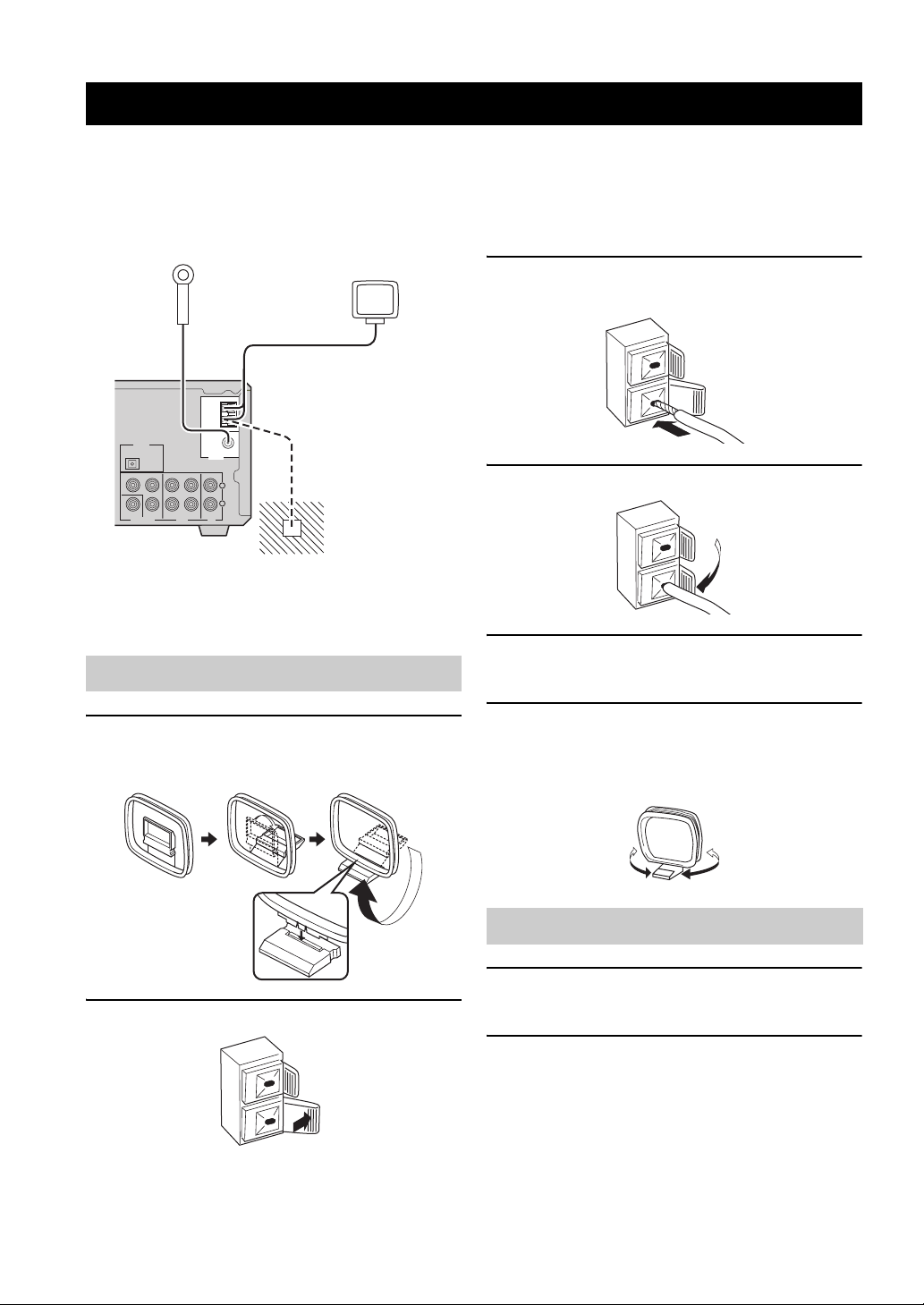
CONNECTING ANTENNAS
To enjoy radio on the DVD receiver, you need to connect AM and FM antennas to the DVD receiver. This product
includes an AM loop antenna and indoor FM antenna. If there is a problem of weak radio wave reception in your area or
you want to improve radio reception, we recommend that you use optional outdoor antennas. For details, consult the
nearest authorized YAMAHA dealer or service center.
Indoor FM
antenna
(supplied)
AM loop
antenna
(supplied)
AM
ANT
GND
P
PR
B
IN INOUT
AUXVIDEO OUT TV
FM ANT
Ω UNBAL.
75
TUNER
L
R
Ground
(GND terminal)
DIGITAL
OPTICAL
OUT
Y
COMPONENT
VIDEO
■ About grounding
For maximum safety and minimum interference, connect
the antenna GND terminal to a good earth ground. A good
earth ground is a metal stake driven into moist earth.
Connecting the AM loop antenna
1 Attach the antenna stand to the antenna.
When attaching the antenna to the wall, you do not
need to use the antenna stand.
3 Insert the AM loop antenna lead wires into
the AM ANT terminal.
4 Release the tab.
5 Repeat steps 2 to 4 to insert the AM loop
antenna lead wires into the GND terminal.
6 Place the antenna away from the DVD
receiver and speaker cables.
While listening to the radio, rotate the antenna head
to find the best angle for reception.
2 Press and hold the tab.
10
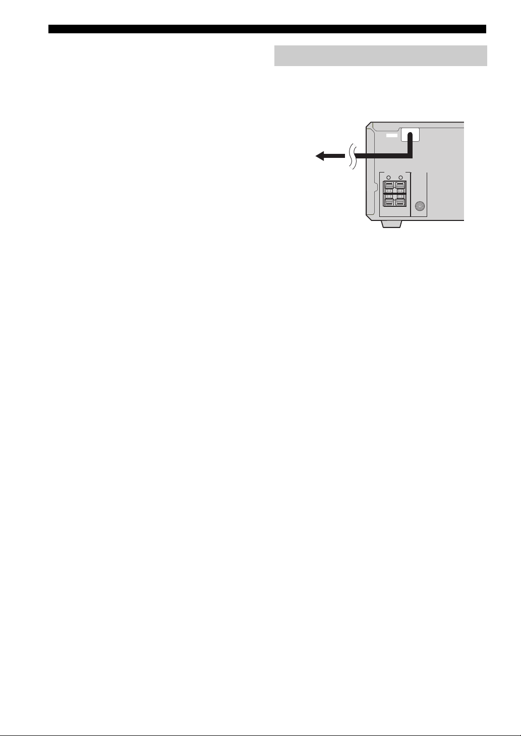
Connecting the FM antenna
1 Connect the supplied indoor FM antenna to
the FM ANT jack on the DVD receiver.
2 Place the antenna away from the DVD
receiver and speaker cables.
CONNECTING EXTERNAL COMPONENTS
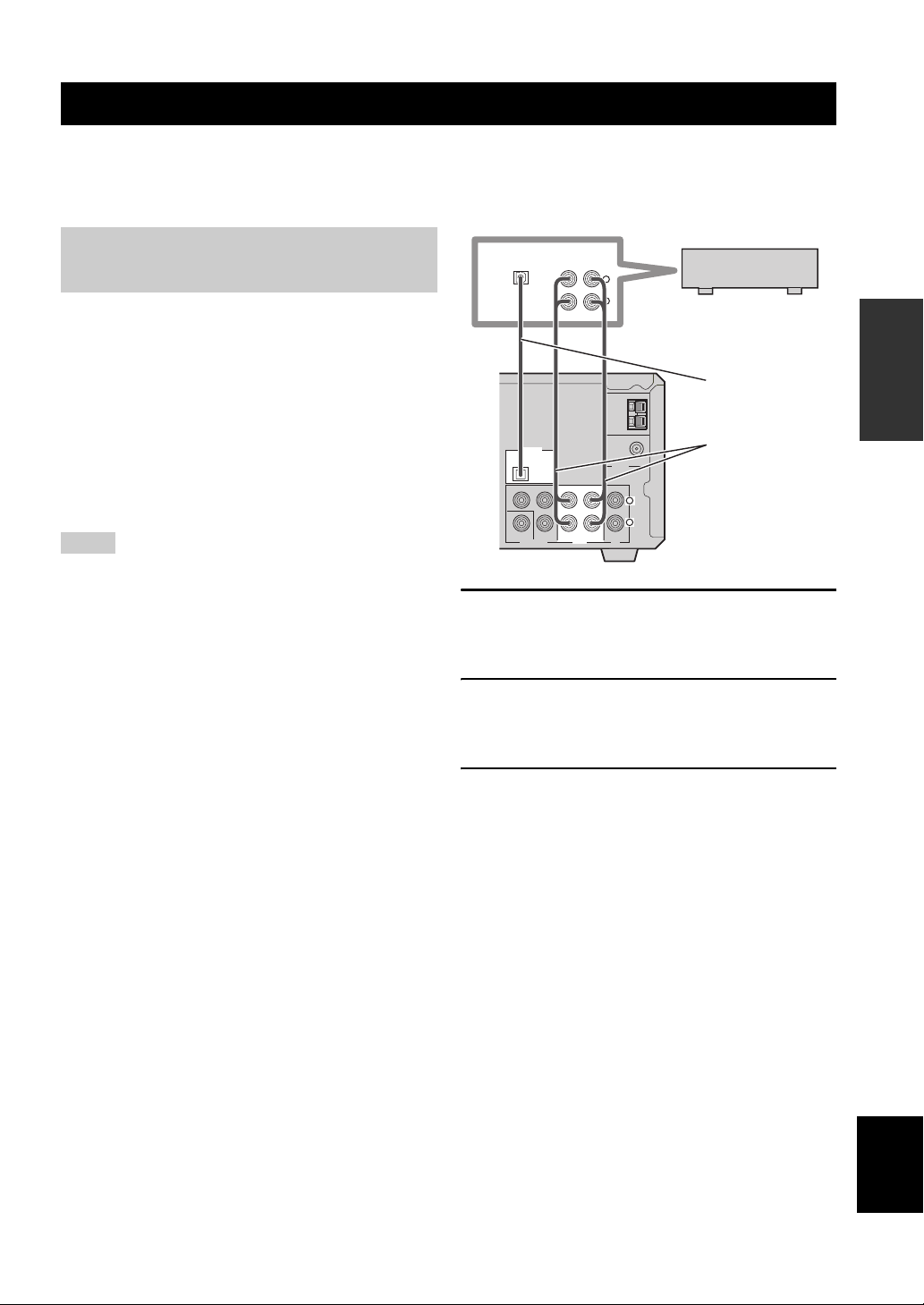
CONNECTING EXTERNAL COMPONENTS
You can connect external components such as a CD recorder or MD recorder to the following jacks on the DVD receiver.
This section provides an example of other equipment connections. For information on your equipments, refer to the
manuals for them.
Connecting a CD recorder or MD
recorder
If you connect a CD recorder or MD recorder to the DVD
receiver using optical cables, you can record audio sources
played on the DVD receiver digitally. Also, you can enjoy
audio sources played on the recorder with the DVD
receiver.
y
AM/FM broadcasts cannot be output from this unit’s DIGITAL
OPTICAL OUT jack. To record AM/FM broadcasts, use a
commercially available audio cable to connect the AUX OUT
jack on the DVD receiver to the analog input jack on your
recorder.
Notes
• Turn off the component before connecting it to the DVD
receiver.
• Do not connect the power cable of the DVD receiver until all
cable connections are completed.
DIGITAL
OPTICAL
ANALOG
IN
OUTIN
L
R
CD recorder or
MD recorder
Optical
AM
ANT
GND
DIGITAL
OPTICAL
OUT
PB
Y
PR
COMPONENT
VIDEO
VIDEO OUT
OUT IN IN
AUX TV
FM ANT
75
Ω UNBAL.
TUNER
L
R
cable
Audio
cable
1 Connect the DIGITAL OPTICAL OUT jack on
the DVD receiver to the digital input jack on
the recorder using an optical cable.
2 Connect the AUX OUT jacks on the DVD
receiver to the analog input jacks on the
recorder using an audio cable.
PREPARATION
3 Connect the AUX IN jacks on the DVD
receiver to the analog output jacks on the
recorder using an audio cable.
English
11
CONNECTING EXTERNAL COMPONENTS
■ About the AUX jacks
• The signal input from the AUX IN jack is not output
from the AUX OUT jack.
• The DVD receiver’s digital and analog signal circuits
are independent of each other. Analog input signals are
output only from analog output jacks.
■ About the DIGITAL jack
• The digital jack is compatible with PCM, Dolby
Digital and DTS signals.
• The digital jack is designed based on EIA standards. To
make a digital connection, use an optical cable that
meets EIA standards.
y
This unit can output a DTS signal digitally. To reproduce a DTS
encoded source, connect the DIGITAL OPTICAL OUT jack on
the DVD receiver to the digital input jack on a component that
features a DTS decoder.
Connecting the Power Cables
After you made all connections, connect the power cables
of the DVD receiver and subwoofer (optional).
MAINS
MAINS
SPEAKERS
SUB WOOFER
To an AC wall outlet
6Ω MIN. /SPEAKER
RL
OUT
12
INSTALLING BATTERIES IN THE REMOTE CONTROL
Press
■ To replace the batteries
Change all of the batteries if the operation range of the remote
controls decreases.
Notes
• Do not use an old battery together with new one.
• Do not use different types of batteries (for example, alkaline
and manganese) together. Each type of battery has its own
characteristics even if they are similar in shape.
• If the batteries run out, immediately remove them from the
remote control to prevent an explosion or acid leak.
• Dispose of the batteries according to the regional regulations.
• If a battery starts leaking, dispose of it immediately. Be careful
not to let leaking battery acid come into contact with your skin
or clothing. Before inserting new batteries, wipe the
compartment clean.
• Replace the batteries within two minutes to preserve the
memory in the remote control.
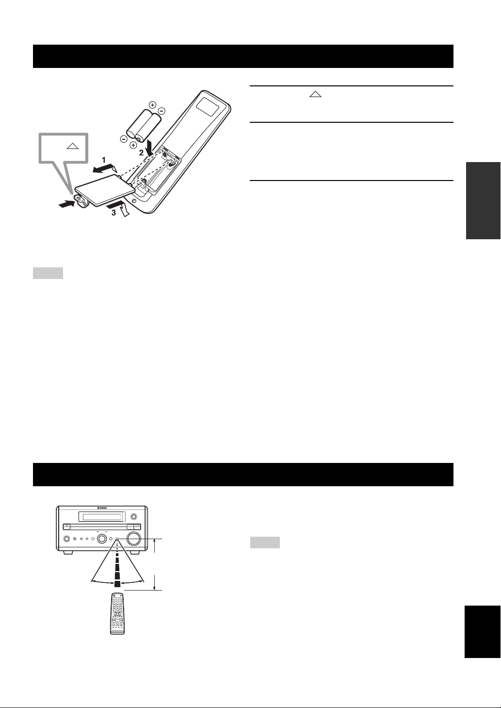
1 Press the mark on the battery cover and
open the cover.
2 Insert the two supplied batteries (AA, R06,
UM-3) into the battery compartment.
Make sure you insert the batteries according to the
polarity markings (+ and –).
3 Close the battery cover.
PREPARATION
USING THE REMOTE CONTROL
INPUT
MULTI JOG
PHONES TIMER
PUSH-ENTER
DISPLAY SOUND MODE
30˚ 30˚
VOLUME
Within 6 m
(20 feet)
STANDBY/ON
Use the remote control within 6 m (20 feet) of the DVD
receiver and point it toward the remote control sensor
(page 3).
Notes
• Be careful not to spill liquid on the remote control.
• Be careful not to drop the remote control.
• Do not leave the remote control in the following places:
– hot or humid places, such as near a heater or in a bathroom
– extremely cold places
– dusty places
English
13

TURNING THE POWER TO ON/STANDBY
TURNING THE POWER TO ON/STANDBY
Press STANDBY/ON once to turn on the DVD
receiver.
Press STANDBY/ON again to set the DVD
receiver to the standby mode.
y
You can set the DVD receiver to the eco standby mode by
pressing DISPLAY on the front panel during standby mode. In
this mode, all display in the DVD receiver turns off. To cancel the
eco standby mode, press DISPLAY during eco mode.
STANDBY/ON ( )
STANDBY/ON
1234
5678
DIMMER
90
REPEAT
+
POWER
TV
SLEEP
A-B
SELECTING AN INPUT SOURCE
You can enjoy various sources with the DVD receiver. After connecting the TV, speakers, antennas, or other equipment,
follow the procedure below to select an input source you want to play on the DVD receiver. For information on
connection methods, refer to pages 8 to 12.
■ To select an input source using INPUT
on the front panel
Press INPUT repeatedly.
Each time you press INPUT, the input source changes as
follows:
DVD/CD
FM
TV
AUX
TV VOL
+
–
EQ
SUBTITLE
ANGLE ZOOM AUDIO
MUTE
NIGHT
VOLUME
+
–
TV
DVD/CD
AUXDIRECT
TUNER
DVD/CD
TUNER
Perform one of the following operations
To switch to DVD/CD input:
Press DVD/CD.
To switch to external source input (external
equipment connected to the DVD receiver):
Press AUX.
To switch to TV input:
Press TV.
U.K. and Europe models only
You can switch the input signals between signals
input at the TV IN jacks and signals input at AV
terminal (page 20).
To switch to tuner input (AM/FM radio):
Press TUNER.
Each time you press TUNER, the input source
switches between AM and FM.
AM
TV/SCART*
AUX
*
SCART is applicable only for U.K and Europe models.
14

TV VOL
+
–
EQ
DIRECT
SUBTITLE
ANGLE ZOOM AUDIO
ADJUSTING THE VOLUME LEVEL
Press VOLUME + to increase the volume level
MUTE
NIGHT
AUX
VOLUME
+
VOLUME +/–
–
TV
DVD/CD
TUNER
and VOLUME – to decrease.
MUTING THE SOUND (MUTE)
ADJUSTING THE VOLUME LEVEL
MUTE
TV VOL
+
–
EQ
DIRECT
SUBTITLE
VOLUME
MUTE
+
NIGHT
–
TV
DVD/CD
AUX
TUNER
ANGLE ZOOM AUDIO
VOLUME +/–
Press MUTE to mute the sound.
To restore audio output to the previous volume level, press
MUTE again or press VOLUME +/–.
OPERATION
BASIC
15
English

ADJUSTING THE CLOCK
ADJUSTING THE CLOCK
1 Press TIMER on the front panel to select
“TIME” and then press MULTI JOG.
2 Rotate MULTI JOG to adjust the hour and
then press MULTI JOG.
STANDBY/ON
PHONES TIMER
MULTI JOG
PUSH-ENTER
DISPLAY SOUND MODE
MULTI JOG
INPUT
VOLUME
3 Rotate MULTI JOG to adjust the minute and
MULTI JOGTIMER
then press MULTI JOG.
4 Press MULTI JOG again to set the time.
Note
You cannot set timer unless you adjust the clock.
SETTING THE TIMER
You can set the timer function so that the DVD receiver turns on at the specified time and begins to play the selected input
source automatically.
1 Press TIMER on the front panel to select
“TIMER” and then press MULTI JOG.
2 Rotate MULTI JOG clockwise to select
“TIMER ON” and then press MULTI JOG.
The current timer setting is displayed.
STANDBY/ON
PHONES TIMER
MULTI JOG
PUSH-ENTER
DISPLAY SOUND MODE
INPUT
VOLUME
16
TIMER
MULTI JOG
3 Set the time that timer play begins using the
MULTI JOG, and then press MULTI JOG.
4 Rotate MULTI JOG to select the input source
to be played and then press MULTI JOG.
5 Rotate MULTI JOG to set the duration (30 to
90 min) and then press MULTI JOG.
You can set the duration in 10 minutes steps.
■ To cancel the timer
Select “TIMER OFF” in step 2.
Loading…
- About
- Blog
- Projects
- Help
-
Donate
Donate icon
An illustration of a heart shape - Contact
- Jobs
- Volunteer
- People
Bookreader Item Preview
texts
Yamaha RDX-E700 Service manual
- Addeddate
- 2020-12-14 18:18:16
- Identifier
- manualzz-id-847606
- Identifier-ark
- ark:/13960/t6r024n1p
- Ocr
- tesseract 4.1.1
- Ocr_autonomous
- true
- Ocr_detected_lang
- la
- Ocr_detected_lang_conf
- 1.0000
- Ocr_detected_script
-
Latin
Cyrillic
Greek
- Ocr_detected_script_conf
-
0.6546
0.2991
0.0384
- Ocr_module_version
- 0.0.10
- Ocr_parameters
- -l ell+lat+eng+kir+que+Latin+Cyrillic+Greek
- Page_number_confidence
- 68.97
comment
Reviews
There are no reviews yet. Be the first one to
write a review.
509
Views
DOWNLOAD OPTIONS
Temporarily Unavailable
DAISY
For users with print-disabilities
Temporarily Unavailable
EPUB
Uploaded by
chris85
on
SIMILAR ITEMS (based on metadata)

YAMAHA ELECTRONICS CORPORATION, USA 6660 ORANGETHORPE AVE., BUENA PARK, CALIF. 90620, U.S.A.
YAMAHA CANADA MUSIC LTD. 135 MILNER AVE., SCARBOROUGH, ONTARIO M1S 3R1, CANADA
YAMAHA ELECTRONIK EUROPA G.m.b.H. SIEMENSSTR. 22-34, 25462 RELLINGEN BEI HAMBURG, GERMANY
YAMAHA ELECTRONIQUE FRANCE S.A. RUE AMBROISE CROIZAT BP70 CROISSY-BEAUBOURG 77312 MARNE-LA-VALLEE CEDEX02, FRANCE
YAMAHA ELECTRONICS (UK) LTD. YAMAHA HOUSE, 200 RICKMANSWORTH ROAD WATFORD, HERTS WD18 7GQ, ENGLAND
YAMAHA SCANDINAVIA A.B. J A WETTERGRENS GATA 1, BOX 30053, 400 43 VÄSTRA FRÖLUNDA, SWEDEN
YAMAHA MUSIC AUSTRALIA PTY, LTD. 17-33 MARKET ST., SOUTH MELBOURNE, 3205 VIC., AUSTRALIA
© 2005 All rights reserved.
OWNER S MANUAL
MODE D EMPLOI
BEDIENUNGSANLEITUNG
BRUKSANVISNING
MANUALE DI ISTRUZIONI
MANUAL DE INSTRUCCIONES
GEBRUIKSAANWIJZING
AMPLI-TUNER DVD
DVD RECEIVER
G
Printed in China
CQX1A1058Z
RDX-E700
Если у вас отсутствует техническая возможность для скачивания Руководство по эксплуатации для Yamaha RDX-E700
вы можете прочесть документ прямо на нашем сайте или
Скачать Yamaha RDX-E700 Руководство по эксплуатации

- 1
- 2
- 3
- 4
- 5
- 6
- 7
- 8
- 9
- 10
- 11
- 12
- 13
- 14
- 15
- 16
- 17
- 18
- 19
- 20
- 21
- 22
- 23
- 24
- 25
- 26
- 27
- 28
- 29
- 30
- 31
- 32
- 33
- 34
- 35
- 36
- 37
- 38
- 39
- 40
- 41
- 42
- 43
- 44
- 45
- 46
- 47
- 48
- 49
- 50
- 51
- 52
- 53
- 54
- 55
- 56
- 57
Инструкции для прочих Yamaha DVD-плееры
-
Yamaha DVD1700 Брошюра
Популярность:
1012 просмотры
Подсчет страниц:
2 страницы
Тип файла:
PDF
Размер файла:
385 Kb