
RX-V365
AV Receiver
OWNER’S MANUAL
F
Caution-i
En
1
To assure the finest performance, please read this manual
carefully. Keep it in a safe place for future reference.
2
Install this sound system in a well ventilated, cool, dry, clean
place – away from direct sunlight, heat sources, vibration,
dust, moisture, and/or cold. Allow ventilation space of at least
30 cm on the top, 20 cm on the left and right, and 20 cm on
the back of this unit.
3
Locate this unit away from other electrical appliances, motors,
or transformers to avoid humming sounds.
4
Do not expose this unit to sudden temperature changes from
cold to hot, and do not locate this unit in an environment with
high humidity (i.e. a room with a humidifier) to prevent
condensation inside this unit, which may cause an electrical
shock, fire, damage to this unit, and/or personal injury.
5
Avoid installing this unit where foreign objects may fall onto
this unit and/or this unit may be exposed to liquid dripping or
splashing. On the top of this unit, do not place:
–
Other components, as they may cause damage and/or
discoloration on the surface of this unit.
–
Burning objects (i.e. candles), as they may cause fire,
damage to this unit, and/or personal injury.
–
Containers with liquid in them, as they may fall and liquid
may cause electrical shock to the user and/or damage to
this unit.
6
Do not cover this unit with a newspaper, tablecloth, curtain,
etc. in order not to obstruct heat radiation. If the temperature
inside this unit rises, it may cause fire, damage to this unit,
and/or personal injury.
7
Do not plug in this unit to a wall outlet until all connections
are complete.
8
Do not operate this unit upside-down. It may overheat,
possibly causing damage.
9
Do not use force on switches, knobs and/or cords.
10 When disconnecting the power cable from the wall outlet,
grasp the plug; do not pull the cable.
11 Do not clean this unit with chemical solvents; this might
damage the finish. Use a clean, dry cloth.
12 Only voltage specified on this unit must be used. Using this
unit with a higher voltage than specified is dangerous and may
cause fire, damage to this unit, and/or personal injury. Yamaha
will not be held responsible for any damage resulting from use
of this unit with a voltage other than specified.
13 To prevent damage by lightning, keep the power cord and
outdoor antennas disconnected from a wall outlet or the unit
during a lightning storm.
14 Do not attempt to modify or fix this unit. Contact qualified
Yamaha service personnel when any service is needed. The
cabinet should never be opened for any reasons.
15 When not planning to use this unit for long periods of time
(i.e. vacation), disconnect the AC power plug from the wall
outlet.
16 Install this unit near the AC outlet and where the AC power
plug can be reached easily.
17 Be sure to read the “Troubleshooting” section on common
operating errors before concluding that this unit is faulty.
18 Before moving this unit, press ASTANDBY/ON to set this
unit in the standby mode, and disconnect the AC power plug
from the wall outlet.
19 VOLTAGE SELECTOR (Asia and General models only)
The VOLTAGE SELECTOR on the rear panel of this unit
must be set for your local main voltage BEFORE plugging
into the AC wall outlet. Voltages are:
………………………………….AC 110–120/220–240 V, 50/60 Hz
20 The batteries shall not be exposed to excessive heat such as
sunshine, fire or like.
21 Excessive sound pressure from earphones and headphones can
cause hearing loss.
22 When replacing the batteries, be sure to use batteries of the
same type. Danger of explosion may happen if batteries are
incorrectly replaced.
■ For U.K. customers
If the socket outlets in the home are not suitable for the
plug supplied with this appliance, it should be cut off and
an appropriate 3 pin plug fitted. For details, refer to the
instructions described below.
The plug severed from the mains lead must be destroyed, as a
plug with bared flexible cord is hazardous if engaged in a live
socket outlet.
■ Special Instructions for U.K. Model
Caution: Read this before operating your unit.
WARNING
TO REDUCE THE RISK OF FIRE OR ELECTRIC
SHOCK, DO NOT EXPOSE THIS UNIT TO RAIN
OR MOISTURE.
As long as this unit is connected to the AC wall outlet,
it is not disconnected from the AC power source even
if you turn off this unit by ASTANDBY/ON. In this
state, this unit is designed to consume a very small
quantity of power.
Note
IMPORTANT
THE WIRES IN MAINS LEAD ARE COLOURED IN
ACCORDANCE WITH THE FOLLOWING CODE:
Blue: NEUTRAL
Brown: LIVE
As the colours of the wires in the mains lead of this apparatus
may not correspond with the coloured markings identifying
the terminals in your plug, proceed as follows:
The wire which is coloured BLUE must be connected to the
terminal which is marked with the letter N or coloured
BLACK. The wire which is coloured BROWN must be
connected to the terminal which is marked with the letter L or
coloured RED.
Making sure that neither core is connected to the earth
terminal of the three pin plug.
Caution-ii
En
Caution: Read this before operating your unit.
Information for Users on Collection and Disposal of Old Equipment and used Batteries
These symbols on the products, packaging, and/or accompanying documents mean that used electrical
and electronic products and batteries should not be mixed with general household waste.
For proper treatment, recovery and recycling of old products and used batteries, please take them to
applicable collection points, in accordance with your national legislation and the Directives 2002/96/
EC and 2006/66/EC.
By disposing of these products and batteries correctly, you will help to save valuable resources and
prevent any potential negative effects on human health and the environment which could otherwise
arise from inappropriate waste handling.
For more information about collection and recycling of old products and batteries, please contact your
local municipality, your waste disposal service or the point of sale where you purchased the items.
[Information on Disposal in other Countries outside the European Union]
These symbols are only valid in the European Union. If you wish to discard these items, please contact
your local authorities or dealer and ask for the correct method of disposal.
Note for the battery symbol (bottom two symbol examples):
This symbol might be used in combination with a chemical symbol. In this case it complies with the
requirement set by the Directive for the chemical involved.
2
En
INTRODUCTION
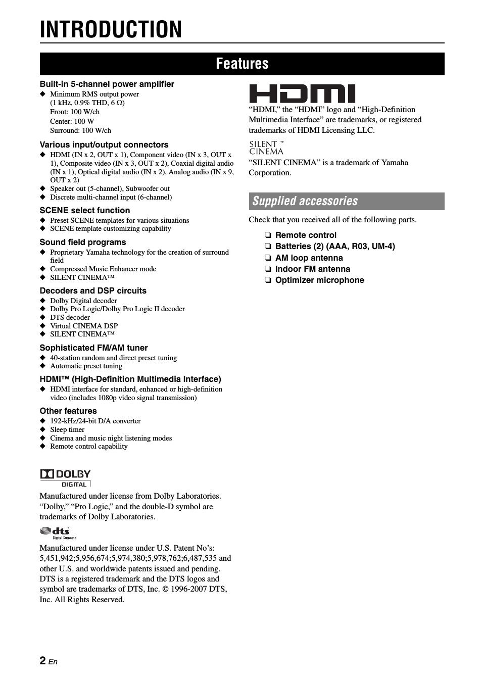
Built-in 5-channel power amplifier
◆ Minimum RMS output power
(1 kHz, 0.9% THD, 6
Ω)
Front: 100 W/ch
Center: 100 W
Surround: 100 W/ch
Various input/output connectors
◆ HDMI (IN x 2, OUT x 1), Component video (IN x 3, OUT x
1), Composite video (IN x 3, OUT x 2), Coaxial digital audio
(IN x 1), Optical digital audio (IN x 2), Analog audio (IN x 9,
OUT x 2)
◆ Speaker out (5-channel), Subwoofer out
◆ Discrete multi-channel input (6-channel)
SCENE select function
◆ Preset SCENE templates for various situations
◆ SCENE template customizing capability
Sound field programs
◆ Proprietary Yamaha technology for the creation of surround
field
◆ Compressed Music Enhancer mode
◆ SILENT CINEMA™
Decoders and DSP circuits
◆ Dolby Digital decoder
◆ Dolby Pro Logic/Dolby Pro Logic II decoder
◆ DTS decoder
◆ Virtual CINEMA DSP
◆ SILENT CINEMA™
Sophisticated FM/AM tuner
◆ 40-station random and direct preset tuning
◆ Automatic preset tuning
HDMI™ (High-Definition Multimedia Interface)
◆ HDMI interface for standard, enhanced or high-definition
video (includes 1080p video signal transmission)
Other features
◆ 192-kHz/24-bit D/A converter
◆ Sleep timer
◆ Cinema and music night listening modes
◆ Remote control capability
Manufactured under license from Dolby Laboratories.
“Dolby,” “Pro Logic,” and the double-D symbol are
trademarks of Dolby Laboratories.
Manufactured under license under U.S. Patent No’s:
5,451,942;5,956,674;5,974,380;5,978,762;6,487,535 and
other U.S. and worldwide patents issued and pending.
DTS is a registered trademark and the DTS logos and
symbol are trademarks of DTS, Inc. © 1996-2007 DTS,
Inc. All Rights Reserved.
“HDMI,” the “HDMI” logo and “High-Definition
Multimedia Interface” are trademarks, or registered
trademarks of HDMI Licensing LLC.
“SILENT CINEMA” is a trademark of Yamaha
Corporation.
Check that you received all of the following parts.
❏ Remote control
❏ Batteries (2) (AAA, R03, UM-4)
❏ AM loop antenna
❏ Indoor FM antenna
❏ Optimizer microphone
Features
Supplied accessories
3
En
English
INTR
ODUCTION
AD
DITIONAL
INFORMA
T
ION
APPENDIX
PRE
P
ARA
T
ION
BA
S
IC
OPERA
T
ION
AD
V
ANCED
OPERA
T
ION
A
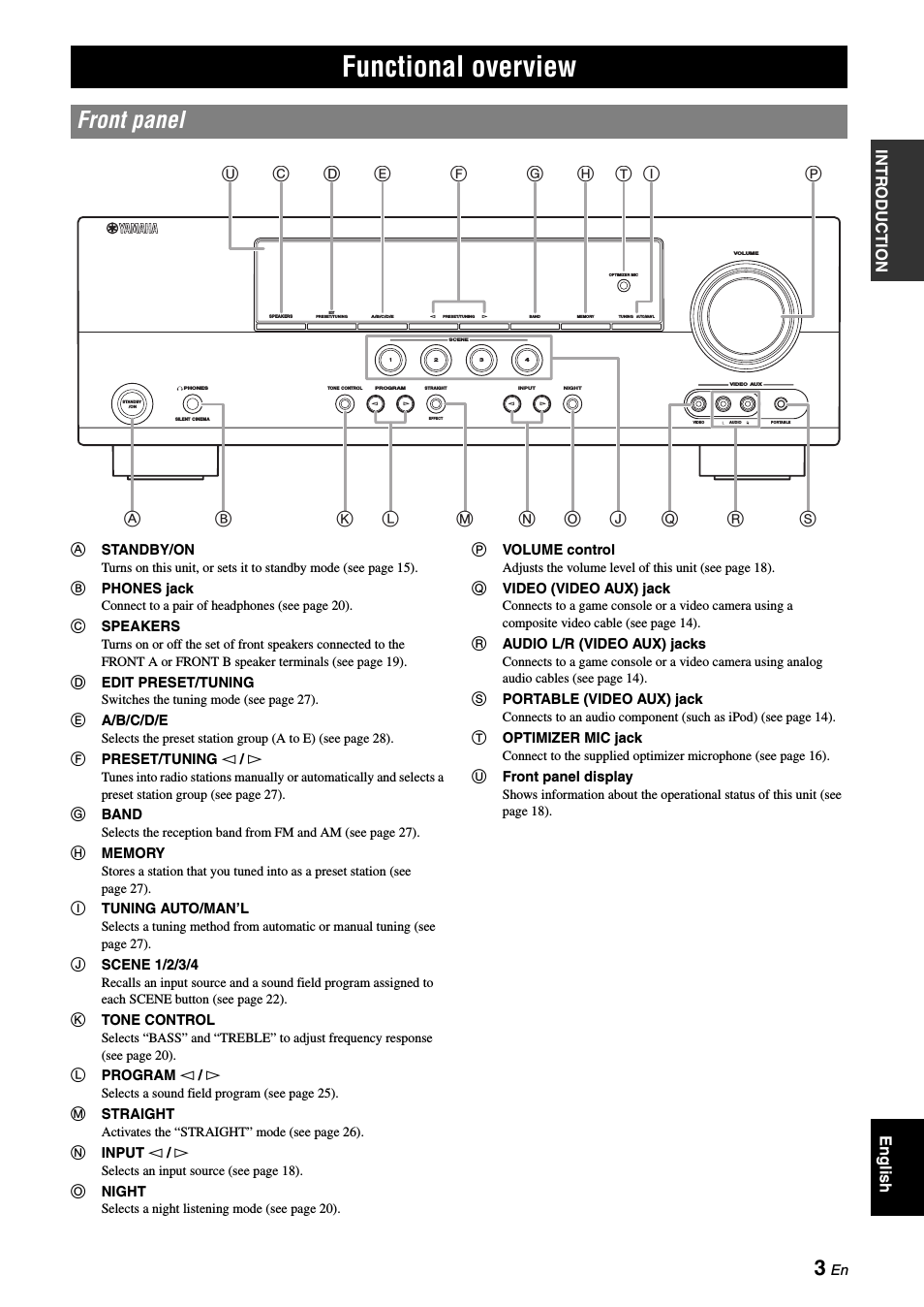
STANDBY/ON
Turns on this unit, or sets it to standby mode (see page 15).
B
PHONES jack
Connect to a pair of headphones (see page 20).
C
SPEAKERS
Turns on or off the set of front speakers connected to the
FRONT A or FRONT B speaker terminals (see page 19).
D
EDIT PRESET/TUNING
Switches the tuning mode (see page 27).
E
A/B/C/D/E
Selects the preset station group (A to E) (see page 28).
F
PRESET/TUNING l / h
Tunes into radio stations manually or automatically and selects a
preset station group (see page 27).
G
BAND
Selects the reception band from FM and AM (see page 27).
H
MEMORY
Stores a station that you tuned into as a preset station (see
page 27).
I
TUNING AUTO/MAN’L
Selects a tuning method from automatic or manual tuning (see
page 27).
J
SCENE 1/2/3/4
Recalls an input source and a sound field program assigned to
each SCENE button (see page 22).
K
TONE CONTROL
Selects “BASS” and “TREBLE” to adjust frequency response
(see page 20).
L
PROGRAM l / h
Selects a sound field program (see page 25).
M
STRAIGHT
Activates the “STRAIGHT” mode (see page 26).
N
INPUT l / h
Selects an input source (see page 18).
O
NIGHT
Selects a night listening mode (see page 20).
P
VOLUME control
Adjusts the volume level of this unit (see page 18).
Q
VIDEO (VIDEO AUX) jack
Connects to a game console or a video camera using a
composite video cable (see page 14).
R
AUDIO L/R (VIDEO AUX) jacks
Connects to a game console or a video camera using analog
audio cables (see page 14).
S
PORTABLE (VIDEO AUX) jack
Connects to an audio component (such as iPod) (see page 14).
T
OPTIMIZER MIC jack
Connect to the supplied optimizer microphone (see page 16).
U
Front panel display
Shows information about the operational status of this unit (see
page 18).
Functional overview
Front panel
OPTIMIZER MIC
PHONES
SILENT CINEMA
TONE CONTROL
PROGRAM
STRAIGHT
INPUT
VIDEO
AUDIO
PORTABLE
VIDEO AUX
VOLUME
EFFECT
l
h
l
h
SCENE
STANDBY
/ON
1
NIGHT
2
3
4
SPEAKERS
PRESET/TUNING
EDIT
A/B/C/D/E
PRESET/TUNING
l
h
BAND
MEMORY
TUNING AUTO/MAN’L
A
C
D
G
H
T
K
O
L
N
I
U
P
E
F
J
Q
S
B
R
M
4
En
Functional overview
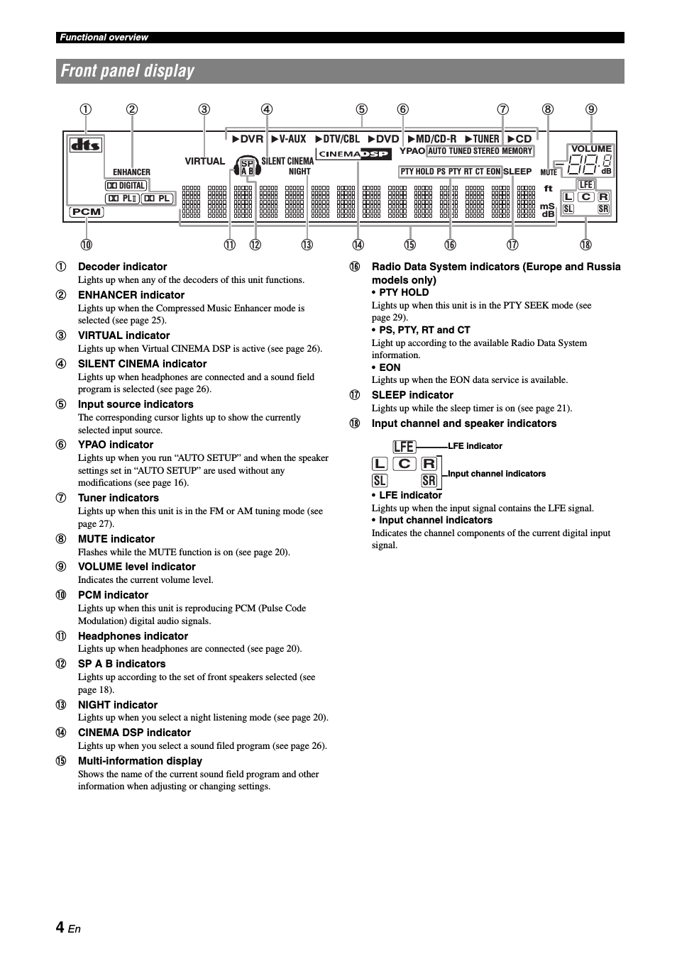
a
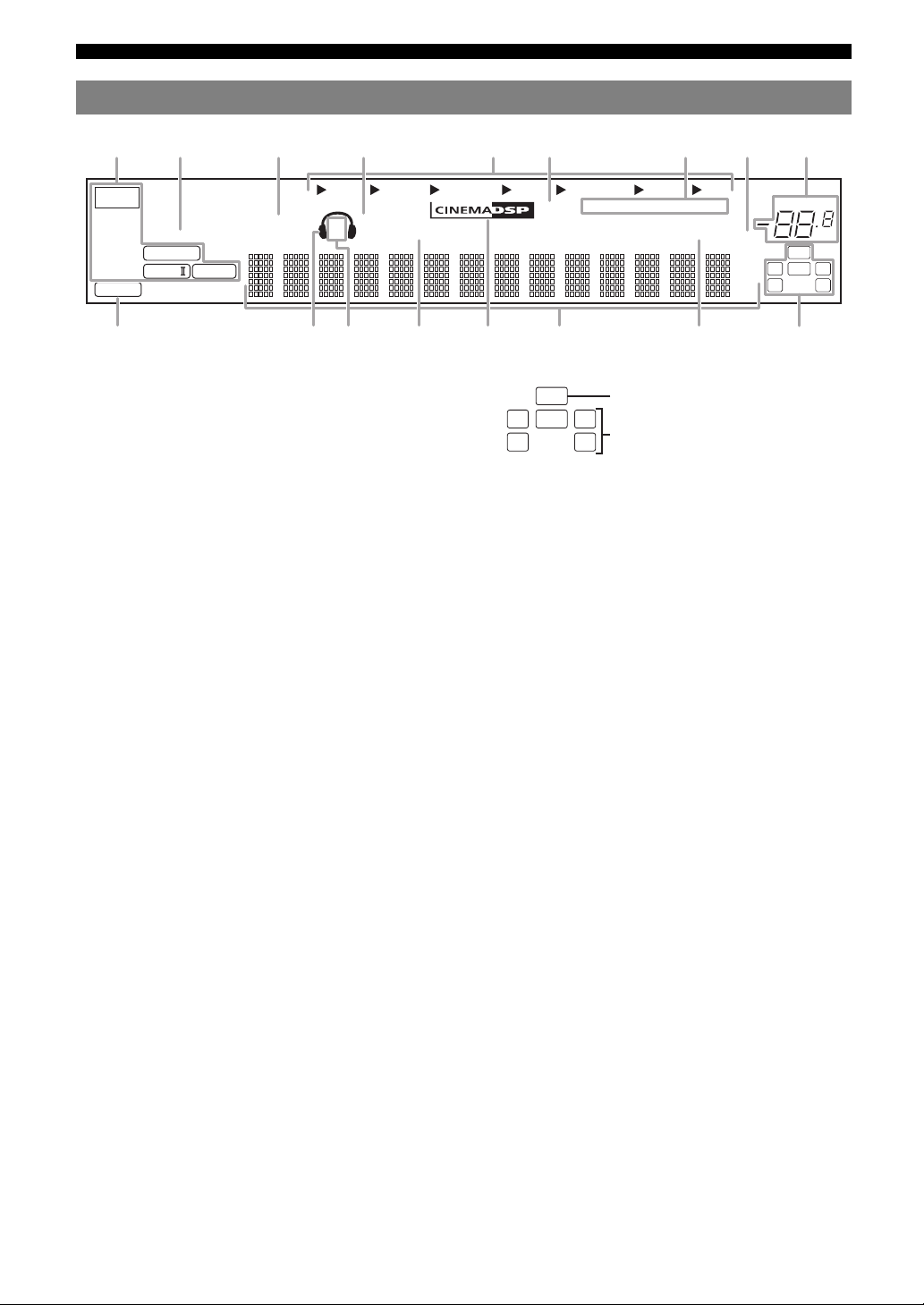
Decoder indicator
Lights up when any of the decoders of this unit functions.
b
ENHANCER indicator
Lights up when the Compressed Music Enhancer mode is
selected (see page 25).
c
VIRTUAL indicator
Lights up when Virtual CINEMA DSP is active (see page 26).
d
SILENT CINEMA indicator
Lights up when headphones are connected and a sound field
program is selected (see page 26).
e
Input source indicators
The corresponding cursor lights up to show the currently
selected input source.
f
YPAO indicator
Lights up when you run “AUTO SETUP” and when the speaker
settings set in “AUTO SETUP” are used without any
modifications (see page 16).
g
Tuner indicators
Lights up when this unit is in the FM or AM tuning mode (see
page 27).
h
MUTE indicator
Flashes while the MUTE function is on (see page 20).
i
VOLUME level indicator
Indicates the current volume level.
j
PCM indicator
Lights up when this unit is reproducing PCM (Pulse Code
Modulation) digital audio signals.
k
Headphones indicator
Lights up when headphones are connected (see page 20).
l
SP A B indicators
Lights up according to the set of front speakers selected (see
page 18).
m
NIGHT indicator
Lights up when you select a night listening mode (see page 20).
n
CINEMA DSP indicator
Lights up when you select a sound filed program (see page 26).
o
Multi-information display
Shows the name of the current sound field program and other
information when adjusting or changing settings.
p
Radio Data System indicators (Europe and Russia
models only)
• PTY HOLD
Lights up when this unit is in the PTY SEEK mode (see
page 29).
• PS, PTY, RT and CT
Light up according to the available Radio Data System
information.
• EON
Lights up when the EON data service is available.
q
SLEEP indicator
Lights up while the sleep timer is on (see page 21).
r
Input channel and speaker indicators
• LFE indicator
Lights up when the input signal contains the LFE signal.
• Input channel indicators
Indicates the channel components of the current digital input
signal.
Front panel display
DVR
DVD
CD
V-AUX
DTV/CBL
MD/CD-R
TUNER
q
PL
q
PL
ENHANCER
SILENT CINEMA
NIGHT
AUTO
YPAO
PRESET
PS
HOLD
RT
EON
PTY
PTY
TUNED
MUTE
VOLUME
MEMORY
SLEEP
VIRTUAL
PCM
A B
SP
mS
ft
dB
LFE
L
C
R
SL
SR
q
DIGITAL
t
dB
STEREO
CT
a
b
c
d
f
e
g
h
i
j
k
l
m
n
o
q
r
p
LFE
L
C
R
SL
SR
LFE indicator
Input channel indicators
5
En
Functional overview
English
INTR
ODUCTION
AD
DITIONAL
INFORMA
T
ION
APPENDIX
PRE
P
ARA
T
ION
BA
S
IC
OPERA
T
ION
AD
V
ANCED
OPERA
T
ION
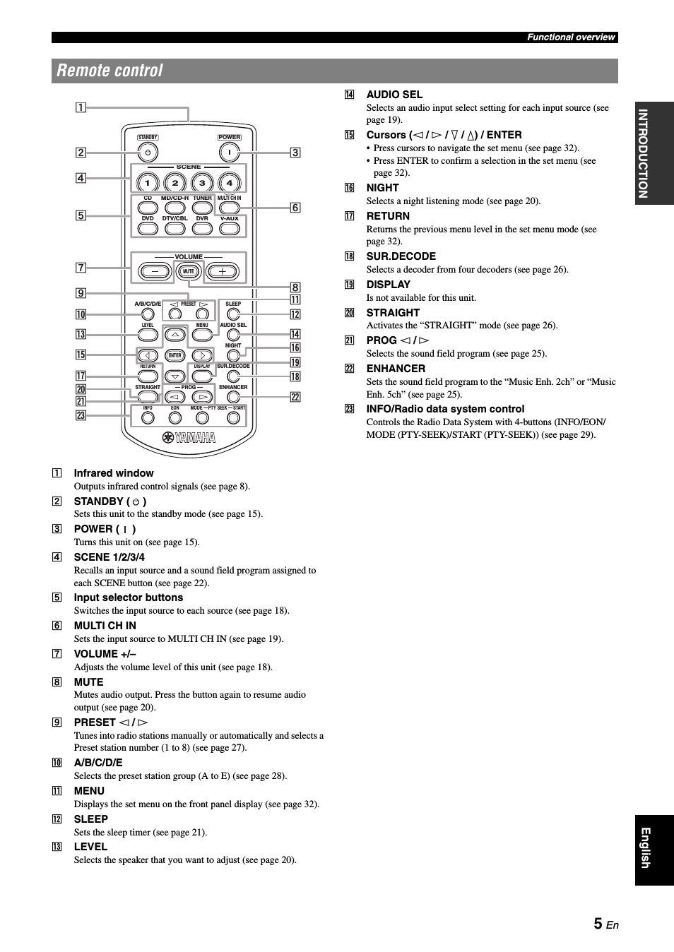
a
Infrared window
Outputs infrared control signals (see page 8).
b
STANDBY (
)
Sets this unit to the standby mode (see page 15).
c
POWER (
)
Turns this unit on (see page 15).
d
SCENE 1/2/3/4
Recalls an input source and a sound field program assigned to
each SCENE button (see page 22).
e
Input selector buttons
Switches the input source to each source (see page 18).
f
MULTI CH IN
Sets the input source to MULTI CH IN (see page 19).
g
VOLUME +/–
Adjusts the volume level of this unit (see page 18).
h
MUTE
Mutes audio output. Press the button again to resume audio
output (see page 20).
i
PRESET l / h
Tunes into radio stations manually or automatically and selects a
Preset station number (1 to  (see page 27).
j
A/B/C/D/E
Selects the preset station group (A to E) (see page 28).
k
MENU
Displays the set menu on the front panel display (see page 32).
l
SLEEP
Sets the sleep timer (see page 21).
m
LEVEL
Selects the speaker that you want to adjust (see page 20).
n
AUDIO SEL
Selects an audio input select setting for each input source (see
page 19).
o
Cursors (l / h / n / k) / ENTER
• Press cursors to navigate the set menu (see page 32).
• Press ENTER to confirm a selection in the set menu (see
page 32).
p
NIGHT
Selects a night listening mode (see page 20).
q
RETURN
Returns the previous menu level in the set menu mode (see
page 32).
r
SUR.DECODE
Selects a decoder from four decoders (see page 26).
s
DISPLAY
Is not available for this unit.
t
STRAIGHT
Activates the “STRAIGHT” mode (see page 26).
u
PROG l / h
Selects the sound field program (see page 25).
v
ENHANCER
Sets the sound field program to the “Music Enh. 2ch” or “Music
Enh. 5ch” (see page 25).
w
INFO/Radio data system control
Controls the Radio Data System with 4-buttons (INFO/EON/
MODE (PTY-SEEK)/START (PTY-SEEK)) (see page 29).
Remote control
STANDBY
SCENE
POWER
CD
DVD
A/B/C/D/E
PRESET
SLEEP
LEVEL
MENU
AUDIO SEL
NIGHT
RETURN
SUR.DECODE
STRAIGHT
INFO
EON
PTY
MODE
PROG
ENHANCER
DISPLAY
ENTER
MUTE
DVR
V-AUX
DTV/CBL
MD/CD-R TUNER
MULTI CH IN
1
2
3
4
VOLUME
START
SEEK
a
b
d
g
k
s
p
t
h
c
f
l
n
r
v
j
m
q
e
i
u
w
o
Rear panel, Acomponent video jacks, Bhdmi terminals
Cvideo jacks, Dantenna terminals, Espeakers terminals, Fdigital input jacks, Gmulti ch input jacks, Haudio jacks, Isubwoofer output jack Чат поддержки
- Изображение
- Текст
6
En
Functional overview
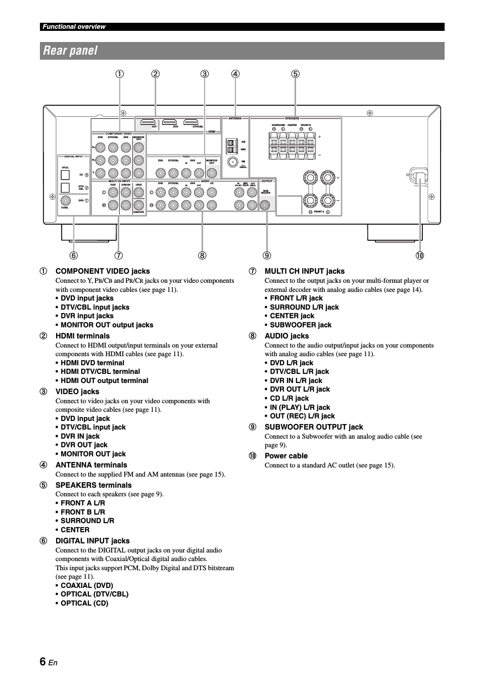
a
COMPONENT VIDEO jacks
Connect to Y, P
B
/C
B
and P
R
/C
R
jacks on your video components
with component video cables (see page 11).
• DVD input jacks
• DTV/CBL input jacks
• DVR input jacks
• MONITOR OUT output jacks
b
HDMI terminals
Connect to HDMI output/input terminals on your external
components with HDMI cables (see page 11).
• HDMI DVD terminal
• HDMI DTV/CBL terminal
• HDMI OUT output terminal
c
VIDEO jacks
Connect to video jacks on your video components with
composite video cables (see page 11).
• DVD input jack
• DTV/CBL input jack
• DVR IN jack
• DVR OUT jack
• MONITOR OUT jack
d
ANTENNA terminals
Connect to the supplied FM and AM antennas (see page 15).
e
SPEAKERS terminals
Connect to each speakers (see page 9).
• FRONT A L/R
• FRONT B L/R
• SURROUND L/R
• CENTER
f
DIGITAL INPUT jacks
Connect to the DIGITAL output jacks on your digital audio
components with Coaxial/Optical digital audio cables.
This input jacks support PCM, Dolby Digital and DTS bitstream
(see page 11).
• COAXIAL (DVD)
• OPTICAL (DTV/CBL)
• OPTICAL (CD)
g
MULTI CH INPUT jacks
Connect to the output jacks on your multi-format player or
external decoder with analog audio cables (see page 14).
• FRONT L/R jack
• SURROUND L/R jack
• CENTER jack
• SUBWOOFER jack
h
AUDIO jacks
Connect to the audio output/input jacks on your components
with analog audio cables (see page 11).
• DVD L/R jack
• DTV/CBL L/R jack
• DVR IN L/R jack
• DVR OUT L/R jack
• CD L/R jack
• IN (PLAY) L/R jack
• OUT (REC) L/R jack
i
SUBWOOFER OUTPUT jack
Connect to a Subwoofer with an analog audio cable (see
page 9).
j
Power cable
Connect to a standard AC outlet (see page 15).
Rear panel
DIGITAL INPUT
COMPONENT VIDEO
VIDEO
AUDIO
MULTI CH INPUT
HDMI
ANTENNA
SPEAKERS
DVD
OPTICAL
DVD
SURROUND
CENTER
FRONT B
FRONT A
DVR
SURROUND
FRONT
CENTER
SUBWOOFER
DTV/CBL
DVD
DVR
FM
AM
GND
IN
OUT
DTV/CBL
DVD
DVR
CD
OUTPUT
SUB
WOOFR
IN
OUT
MD/
CD-R
IN
(PLAY)
OUT
(REC)
DTV/CBL
DTV/CBL
MONITOR
OUT
MONITOR
OUT
CD
P
R
P
B
Y
DVD
COAXIAL
DTV/
CBL
OUT
UNBAL.
f
g
h
i
d
e
b
c
a
j
09:26
S 90F и усилитель YAMAHA RX-V373 ( бюджетная аудиосистема обзор )
10:46
Обзор AV ресиверов Yamaha RX-V381 и Yamaha RX-V481
21:56
Как я настроил звук на ресивере Ямаха
09:52
Yamaha RX-V365 Receiver and energy speaker review
01:46
Yamaxa rx-v365 Ultimate Sym 3
01:44
Yamaha RX-V365 — Amplificateur audio-vidéo
11:23
YAMAHA CDX-470 & YAMAHA RX-V365
Нажмите на кнопку для помощи

RX-V365
AV Receiver
RL
OWNER’S MANUAL
MANUAL DE INSTRUCCIONES

Caution: Read this before operating your unit.
1 To assure the finest performance, please read this manual
carefully. Keep it in a safe place for future reference.
2 Install this sound system in a well ventilated, cool, dry, clean
place – away from direct sunlight, heat sources, vibration,
dust, moisture, and/or cold. Allow ventilation space of at least
30 cm on the top, 20 cm on the left and right, and 20 cm on
the back of this unit.
3 Locate this unit away from other electrical appliances, motors,
or transformers to avoid humming sounds.
4 Do not expose this unit to sudden temperature changes from
cold to hot, and do not locate this unit in an environment with
high humidity (i.e. a room with a humidifier) to prevent
condensation inside this unit, which may cause an electrical
shock, fire, damage to this unit, and/or personal injury.
5 Avoid installing this unit where foreign objects may fall onto
this unit and/or this unit may be exposed to liquid dripping or
splashing. On the top of this unit, do not place:
– Other components, as they may cause damage and/or
discoloration on the surface of this unit.
– Burning objects (i.e. candles), as they may cause fire,
damage to this unit, and/or personal injury.
– Containers with liquid in them, as they may fall and liquid
may cause electrical shock to the user and/or damage to
this unit.
6 Do not cover this unit with a newspaper, tablecloth, curtain,
etc. in order not to obstruct heat radiation. If the temperature
inside this unit rises, it may cause fire, damage to this unit,
and/or personal injury.
7 Do not plug in this unit to a wall outlet until all connections
are complete.
8 Do not operate this unit upside-down. It may overheat,
possibly causing damage.
9 Do not use force on switches, knobs and/or cords.
10 When disconnecting the power cable from the wall outlet,
grasp the plug; do not pull the cable.
11 Do not clean this unit with chemical solvents; this might
damage the finish. Use a clean, dry cloth.
12 Only voltage specified on this unit must be used. Using this
unit with a higher voltage than specified is dangerous and may
cause fire, damage to this unit, and/or personal injury. Yamaha
will not be held responsible for any damage resulting from use
of this unit with a voltage other than specified.
13 To prevent damage by lightning, keep the power cord and
outdoor antennas disconnected from a wall outlet or the unit
during a lightning storm.
14 Do not attempt to modify or fix this unit. Contact qualified
Yamaha service personnel when any service is needed. The
cabinet should never be opened for any reasons.
15 When not planning to use this unit for long periods of time
(i.e. vacation), disconnect the AC power plug from the wall
outlet.
16 Install this unit near the AC outlet and where the AC power
plug can be reached easily.
17 Be sure to read the “Troubleshooting” section on common
operating errors before concluding that this unit is faulty.
18 Before moving this unit, press ASTANDBY/ON to set this
unit in the standby mode, and disconnect the AC power plug
from the wall outlet.
19 VOLTAGE SELECTOR (Asia and General models only)
The VOLTAGE SELECTOR on the rear panel of this unit
must be set for your local main voltage BEFORE plugging
into the AC wall outlet. Voltages are:
…………………………………. AC 110–120/220–240 V, 50/60 Hz
20 The batteries shall not be exposed to excessive heat such as
sunshine, fire or like.
21 Excessive sound pressure from earphones and headphones can
cause hearing loss.
22 When replacing the batteries, be sure to use batteries of the
same type. Danger of explosion may happen if batteries are
incorrectly replaced.
WARNING
TO REDUCE THE RISK OF FIRE OR ELECTRIC
SHOCK, DO NOT EXPOSE THIS UNIT TO RAIN
OR MOISTURE.
As long as this unit is connected to the AC wall outlet,
it is not disconnected from the AC power source even
if you turn off this unit by ASTANDBY/ON. In this
state, this unit is designed to consume a very small
quantity of power.
Caution-i En

Contents
INTRODUCTION
Features………………………………………………………….. 2
Supplied accessories ………………………………………….. 2
Functional overview………………………………………… 3
Front panel ……………………………………………………….. 3
Front panel display…………………………………………….. 4
Remote control………………………………………………….. 5
Rear panel ………………………………………………………… 6
Quick start guide…………………………………………….. 7
L
PREPARATION
Preparation of remote control …………………………. 8
Connections …………………………………………………….9
Placing speakers………………………………………………… 9
Connecting speakers ………………………………………….. 9
Connecting video components …………………………… 11
Connecting other components …………………………… 13
Using the VIDEO AUX jacks on the front panel ….14
Connecting the FM and AM antennas ………………… 15
Connecting the power cable………………………………. 15
Turning on and off the power ……………………………. 15
Optimizing the speaker setting for your listening
room (YPAO) ……………………………………………. 16
Using AUTO SETUP……………………………………….. 16
BASIC OPERATION
Playback……………………………………………………….. 18
Basic procedure……………………………………………….. 18
Additional operations……………………………………….. 19
Selecting the SCENE templates ……………………… 22
Selecting the desired SCENE template……………….. 22
Creating your original SCENE templates …………….24
Using remote control on the SCENE feature ……….. 25
Sound field programs ……………………………………. 26
Selecting sound field programs………………………….. 26
FM/AM tuning ………………………………………………28
Overview………………………………………………………… 28
FM/AM tuning operations ………………………………… 28
Preset FM/AM stations …………………………………….. 28
ADVANCED OPERATION
Set menu ………………………………………………………. 30
Using set menu………………………………………………… 31
1 SOUND MENU ……………………………………………. 31
2 INPUT MENU ……………………………………………… 33
3 OPTION MENU …………………………………………… 34
Remote control features ………………………………… 36
Controlling this unit, a TV, or other components …. 36
Setting remote control codes……………………………… 38
Advanced setup …………………………………………….. 39
ADDITIONAL INFORMATION
Troubleshooting ……………………………………………. 40
Glossary ……………………………………………………….. 45
Specifications………………………………………………… 46
Index ……………………………………………………………. 47
APPENDIX
(at the end of this manual)
List of remote control codes…………………………….. i
About this manual
• y indicates a tip for your operation.
• Some operations can be performed by using either the buttons on the
front panel or the ones on the remote control. In case the button
names differ between the front panel and the remote control, the
button name on the remote control is given in parentheses.
• This manual is printed prior to production. Design and specifications
are subject to change in part as a result of improvements, etc. In case
of differences between the manual and product, the product has
priority.
• “ASTANDBY/ON” or “fDVD” (example) indicates the name of
the parts on the front panel or the remote control. Refer to the
“Functional overview” on page 3.
INTRODUCTION
PREPARATION
OPERATION
BASIC
OPERATION
ADVANCED
INFORMATION
ADDITIONAL
1 En
APPENDIX
English

INTRODUCTION
Features
Built-in 5-channel power amplifier
(1 kHz, 0.9% THD, 6 Ω)
Front: 100 W/ch
Center: 100 W
Surround: 100 W/ch
Various input/output connectors
◆ HDMI (IN x 2, OUT x 1), Component video (IN x 3, OUT x
1), Composite video (IN x 3, OUT x 2), Coaxial digital audio
(IN x 1), Optical digital audio (IN x 2), Analog audio (IN x 9,
OUT x 2)
◆ Speaker out (5-channel), Subwoofer out
◆ Discrete multi-channel input (6-channel)
SCENE select function
◆ Preset SCENE templates for various situations
◆ SCENE template customizing capability
Sound field programs
◆ Proprietary Yamaha technology for the creation of surround
field
◆ Compressed Music Enhancer mode
◆ SILENT CINEMA™
Decoders and DSP circuits
◆ Dolby Digital decoder
◆ Dolby Pro Logic/Dolby Pro Logic II decoder
◆ DTS decoder
◆ Virtual CINEMA DSP
◆ SILENT CINEMA™
Sophisticated FM/AM tuner
◆ 40-station random and direct preset tuning
◆ Automatic preset tuning
HDMI™ (High-Definition Multimedia Interface)
◆ HDMI interface for standard, enhanced or high-definition
video (includes 1080p video signal transmission)
Other features
◆ 192-kHz/24-bit D/A converter
◆ Sleep timer
◆ Cinema and music night listening modes
◆ Remote control with preset remote control codes
“HDMI,” the “HDMI” logo and “High-Definition
Multimedia Interface” are trademarks, or registered
trademarks of HDMI Licensing LLC.
“SILENT CINEMA” is a trademark of Yamaha
Corporation.
Supplied accessories
Check that you received all of the following parts.
❏ Remote control
❏ Batteries (2) (AAA, R03, UM-4)
❏ AM loop antenna
❏ Indoor FM antenna
❏ Optimizer microphone
Manufactured under license from Dolby Laboratories.
“Dolby,” “Pro Logic,” and the double-D symbol are
trademarks of Dolby Laboratories.
Manufactured under license under U.S. Patent No’s:
5,451,942;5,956,674;5,974,380;5,978,762;6,487,535 and
other U.S. and worldwide patents issued and pending.
DTS is a registered trademark and the DTS logos and
symbol are trademarks of DTS, Inc. © 1996-2007 DTS,
Inc. All Rights Reserved.
2 En

Front panel
STANDBY
/ON
SILENT
PHONES
CINEMA
SPEAKERS
Functional overview
EDIT
PRESET/TUNING
TONE
CONTROL
A/B/C/D/E
PROGRAM
l
l
h
PRESET/TUNING
SCENE
1
2
3
STRAIGHT
h
EFFECT
l
INTRODUCTION
VOLUME
OPTIMIZER
MIC
PREPARATION
MEMORY
BAND
4
INPUT
NIGHT
h
TUNING
AUTO/MAN’L
AUX
VIDEO
VIDEO
AUDIO
PORTABLE
OPERATION
BASIC
A
K OL N
A STANDBY/ON
Turns on this unit, or sets it to standby mode (see page 15).
B PHONES jack
Connect to a pair of headphones (see page 20).
C SPEAKERS
Turns on or off the set of front speakers connected to the
FRONT A or FRONT B speaker terminals (see page 19).
D EDIT PRESET/TUNING
Switches the tuning mode (see page 28).
E A/B/C/D/E
Selects the preset station group (A to E) (see page 29).
F PRESET/TUNING l / h
Tunes into radio stations manually or automatically and selects a
preset station group (see page 28).
G BAND
Selects the reception band from FM and AM (see page 28).
H MEMORY
Stores a station that you tuned into as a preset station (see
page 28).
I TUNING AUTO/MAN’L
Selects a tuning method from automatic or manual tuning (see
page 28).
J SCENE 1/2/3/4
Recalls an input source and a sound field program assigned to
each SCENE button (see page 22).
K TONE CONTROL
Selects “BASS” and “TREBLE” to adjust frequency response
(see page 20).
L PROGRAM l / h
Selects a sound field program (see page 26).
M STRAIGHT
Activates the “STRAIGHT” mode (see page 27).
N INPUT l / h
Selects an input source (see page 18).
O NIGHT
Selects a night listening mode (see page 20).
J Q SB RM
P VOLUM E control
Adjusts the volume level of this unit (see page 18).
Q VIDEO (VIDEO AUX) jack
Connects to a game console or a video camera using a
composite video cable (see page 14).
R AUDIO L/R (VIDEO AUX) jacks
Connects to a game console or a video camera using analog
audio cables (see page 14).
S PORTABLE (VIDEO AUX) jack
Connects to an audio component (such as iPod) (see page 14).
T OPTIMIZER MIC jack
Connect to the supplied optimizer microphone (see page 16).
U Front panel display
Shows information about the operational status of this unit (see
page 18).
OPERATION
ADVANCED
INFORMATION APPENDIX
ADDITIONAL
English
3 En
Functional overview
Front panel display
t
PCM
ENHANCER
q
DIGITAL
q
PL
q
VIRTUAL
PL
DVR DVD CD
a Decoder indicator
Lights up when any of the decoders of this unit functions.
b ENHANCER indicator
Lights up when the Compressed Music Enhancer mode is
selected (see page 26).
c VIRTUAL indicator
Lights up when Virtual CINEMA DSP is active (see page 27).
d SILENT CINEMA indicator
Lights up when headphones are connected and a sound field
program is selected (see page 27).
SILENT CINEMA
SP
A B
V-AUX DTV/CBL
NIGHT
YPAO
MD/CD-R
AUTO
TUNED
TUNER
STEREO
MEMORY
PRESET
SLEEP
MUTE
ft
mS
dB
q Input channel and speaker indicators
LFE
LCR
SL SR
• LFE indicator
Lights up when the input signal contains the LFE signal.
• Input channel indicators
Indicates the channel components of the current digital input
signal.
LFE indicator
Input channel indicators
VOLUME
dB
LFE
LCR
SL SR
e Input source indicators
The corresponding cursor lights up to show the currently
selected input source.
f YPAO indicator
Lights up when you run “AUTO SETUP” and when the speaker
settings set in “AUTO SETUP” are used without any
modifications (see page 16).
g Tuner indicators
Lights up when this unit is in the FM or AM tuning mode (see
page 28).
h MUTE indicator
Flashes while the MUTE function is on (see page 20).
i VOLUME level indicator
Indicates the current volume level.
j PCM indicator
Lights up when this unit is reproducing PCM (Pulse Code
Modulation) digital audio signals.
k Headphones indicator
Lights up when headphones are connected (see page 20).
l SP A B indicators
Lights up according to the set of front speakers selected (see
page 18).
m NIGHT indicator
Lights up when you select a night listening mode (see page 20).
n CINEMA DSP indicator
Lights up when you select a sound filed program (see page 27).
o Multi-information display
Shows the name of the current sound field program and other
information when adjusting or changing settings.
p SLEEP indicator
Lights up while the sleep timer is on (see page 21).
4 En

Remote control
POWER
POWER POWER
b
TV
ABAVC
CD
DVD
f
V-AU X
AMP
h
i
12
BAND LEVEL
TITLE
j
E
/
D
/
C
l
n
/
B
/
A
RETURN
REC
p
q
t
v
PROG
STRAIGHT
MULTI CH IN
9
w
a Infrared window
Outputs infrared control signals (see page 8).
b TV/AV POWER
Turns your TV or other components on or off (see page 37).
c STANDBY ( )
Sets this unit to the standby mode (see page 15).
d POWER ( )
Turns this unit on (see page 15).
e MUTE
Mutes audio output (see page 20).
f Input selector buttons
Switches the input source to each source (see page 18).
g TV control buttons
Controls your TV (see page 36).
STANDBY
MD/CD-R
TUNER
DTV/CBL
DVR
D E
TV INPUT TV MUTE
SCENE
E
T
S
/
C
E
H
R
P
ENTER
P
H
R
C
E
/
T
S
E
ENHANCER
2341
NIGHT
607
AUDIO SEL
MUTE
TV CH
TV VOL
34
VOLUME
MENU
A
/
B
/
C
/
D
/
E
DISPLAY
SUR.DECODE
SLEEP
ENT
10
85
c
d
e
g
k
m
o
r
s
u
x
y
Functional overview
h AMP
Press this button before you control this unit (see page 18).
i SCENE 1/2/3/4
Recalls an input source and a sound field program assigned to
each SCENE button (see page 22).
j BAND LEVEL TITLE
Selects the speaker that you want to adjust (see page 20).
k MENU
Displays the set menu on the front panel display (see page 31).
l Cursors (l / h / n / k) / ENTER
• Press cursors to navigate the set menu (see page 31).
• Press ENTER to confirm a selection in the set menu (see
page 31).
m VOLUM E +/–
Adjusts the volume level of this unit (see page 18).
n RETURN
Returns the previous menu level when the set menu is displayed
(see page 31).
o DISPLAY
Displays the information of external components (such as a
DVD player) (see page 37).
p Control buttons
Control external components (such as a DVD player) connected
to this unit (see page 37).
q PROG l / h
Selects the sound field program (see page 26).
r ENHANCER
Sets the sound field program to the “Music Enh. 2ch” or “Music
Enh. 5ch” (see page 26).
s SUR.DECODE
Selects a decoder from four decoders (see page 27).
t STRAIGHT
Activates the “STRAIGHT” mode (see page 27).
u NIGHT
Selects a night listening mode (see page 20).
v MULTI CH IN
Sets the input source to MULTI CH IN (see page 19).
w AUDIO SEL
Selects an audio input select setting for each input source (see
page 19).
x SLEEP
Sets the sleep timer (see page 21).
y Numeric buttons
Enter remote control codes or preset station number (see
page 38).
INTRODUCTION
PREPARATION
OPERATION
BASIC
OPERATION
ADVANCED
INFORMATION APPENDIX
ADDITIONAL
English
5 En

Functional overview
Rear panel
DIGITAL INPUT
OPTICAL
COAXIAL
COMPONENT VIDEO
DVD
DVR
DTV/CBL
P
R
P
B
Y
CD
DTV/
CBL
DVD
MULTI CH INPUT
SURROUND
FRONT
MONITOR
OUT
CENTER
SUBWOOFER
OUT
DVD
DVD
DTV/CBL
DTV/CBL
DTV/CBL
DVD
VIDEO
DVR
IN
DVR
IN
f g h i
a COMPONENT VIDEO jacks
Connect to Y, PB/CB and PR/CR jacks on your video components
with component video cables (see page 11).
• DVD input jacks
• DTV/CBL input jacks
• DVR input jacks
• MONITOR OUT output jacks
b HDMI terminals
Connect to HDMI output/input terminals on your external
components with HDMI cables (see page 11).
• HDMI DVD terminal
• HDMI DTV/CBL terminal
• HDMI OUT output terminal
c VIDEO jacks
Connect to video jacks on your video components with
composite video cables (see page 11).
• DVD input jack
• DTV/CBL input jack
• DVR IN jack
• DVR OUT jack
• MONITOR OUT jack
d ANTENNA terminals
Connect to the supplied FM and AM antennas (see page 15).
e SPEAKERS terminals
Connect to each speakers (see page 9).
• FRONT A L/R
• FRONT B L/R
• SURROUND L/R
• CENTER
f DIGITAL INPUT jacks
Connect to the DIGITAL output jacks on your digital audio
components with Coaxial/Optical digital audio cables.
This input jacks support PCM, Dolby Digital and DTS bitstream
(see page 11).
• COAXIAL (DVD)
• OPTICAL (DTV/CBL)
• OPTICAL (CD)
ANTENNA
HDMI
AM
GND
MONITOR
OUT
OUT
AUDIO
CD
OUT
FM
UNBAL.
MD/
IN
OUT
CD-R
(PLAY)
(REC)
OUTPUT
WOOFR
SPEAKERS
SURROUND
CENTER
FRONT B
SUB
FRONT A
jk
g MULTI CH INPUT jacks
Connect to the output jacks on your multi-format player or
external decoder with analog audio cables (see page 14).
• FRONT L/R jack
• SURROUND L/R jack
•CENTER jack
• SUBWOOFER jack
h AUDIO jacks
Connect to the audio output/input jacks on your components
with analog audio cables (see page 11).
• DVD L/R jack
• DTV/CBL L/R jack
• DVR IN L/R jack
• DVR OUT L/R jack
• CD L/R jack
• IN (PLAY) L/R jack
• OUT (REC) L/R jack
i SUBWOOFER OUTPUT jack
Connect to a Subwoofer with an analog audio cable (see
page 9).
j VOLTAGE SELECTOR
Select the switch position according to your local voltage (see
page 15).
k Power cable
Connect to a standard AC outlet (see page 15).
6 En
Quick start guide
The following steps describe the easiest way to operate this unit. See the related pages for details on the operation and
settings.
Step 1: Check the items
Step 3: Connect your components
INTRODUCTION
In these steps, you need the following items which are not
included in the package of this unit.
❏ Speakers
We recommend magnetically shielded speakers.
❏ Front speaker ………………………………. x 2
At least two front speakers are required to start
playback.
❏ Center speaker …………………………….. x 1
❏ Surround speaker ………………………… x 2
❏ Active subwoofer …………………………….. x 1
Select an active subwoofer equipped with an RCA
input jack.
❏ Speaker cable ………………………………….. x 5
❏ Subwoofer cable ………………………………. x 1
Select a monaural RCA cable.
❏ DVD player ………………………………………. x 1
Select DVD player equipped with coaxial digital
audio output jack and composite video output jack.
❏ Video monitor ………………………………….. x 1
Select a TV monitor, video monitor or projector
equipped with a composite video input jack.
❏ Video cable ……………………………………… x 2
Select an RCA composite video cable.
❏ Digital coaxial audio cable ……………….. x 1
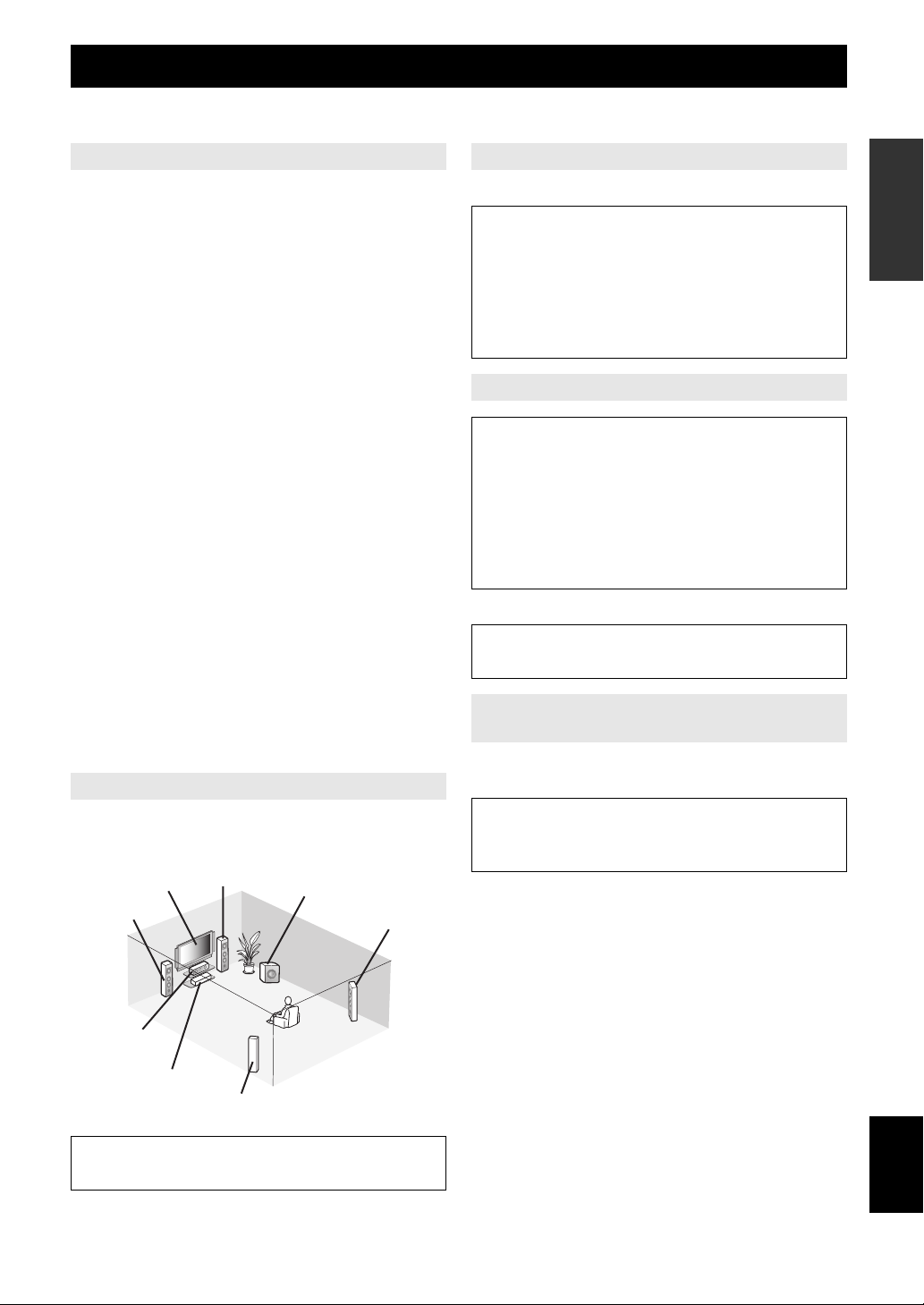
Step 2: Set up your speakers
Place your speakers in the room and connect them to this
unit.
Front right
Video monitor
Front left
speaker
speaker
Subwoofer
Surround right
speaker
Connect your TV, DVD player or other components.
• Connecting a TV monitor or projector ☞P. 1 2
• Connecting audio and video components ☞P. 1 3
• Connecting a multi-format player or an external
decoder ☞P. 1 4
• Using the VIDEO AUX jacks on the front panel
☞P. 1 4
• Connecting the FM and AM antennas ☞P. 1 5
Step 4: Turn on the power
Caution
The VOLTAGE SELECTOR on the rear panel of this
unit must be set for your local voltage BEFORE
plugging the power cable into the AC wall outlet.
Improper setting of the VOLTAGE SELECTOR may
cause damage to this unit and create a potential fire
hazard. See page 15 for details on how to set the
VOLTAGE SELECTOR.
Connect the power cable and turn on this unit.
• Connecting the power cable ☞P. 1 5
• Turning on and off the power ☞P. 1 5
Step 5: Select the input source and start
playback
Select the component connected in the step 3 as an input
source and start playback.
• Basic procedure ☞P. 1 8
• Selecting the SCENE templates ☞P. 2 2
• Adjusting the sound field programs ☞P. 2 6
PREPARATION
OPERATION
BASIC
OPERATION
ADVANCED
INFORMATION APPENDIX
ADDITIONAL
Center speaker
DVD p layer
Surround left
speaker
• Placing speakers ☞P. 9
• Connecting speakers ☞P. 9
English
7 En
PREPARATION
Preparation of remote control
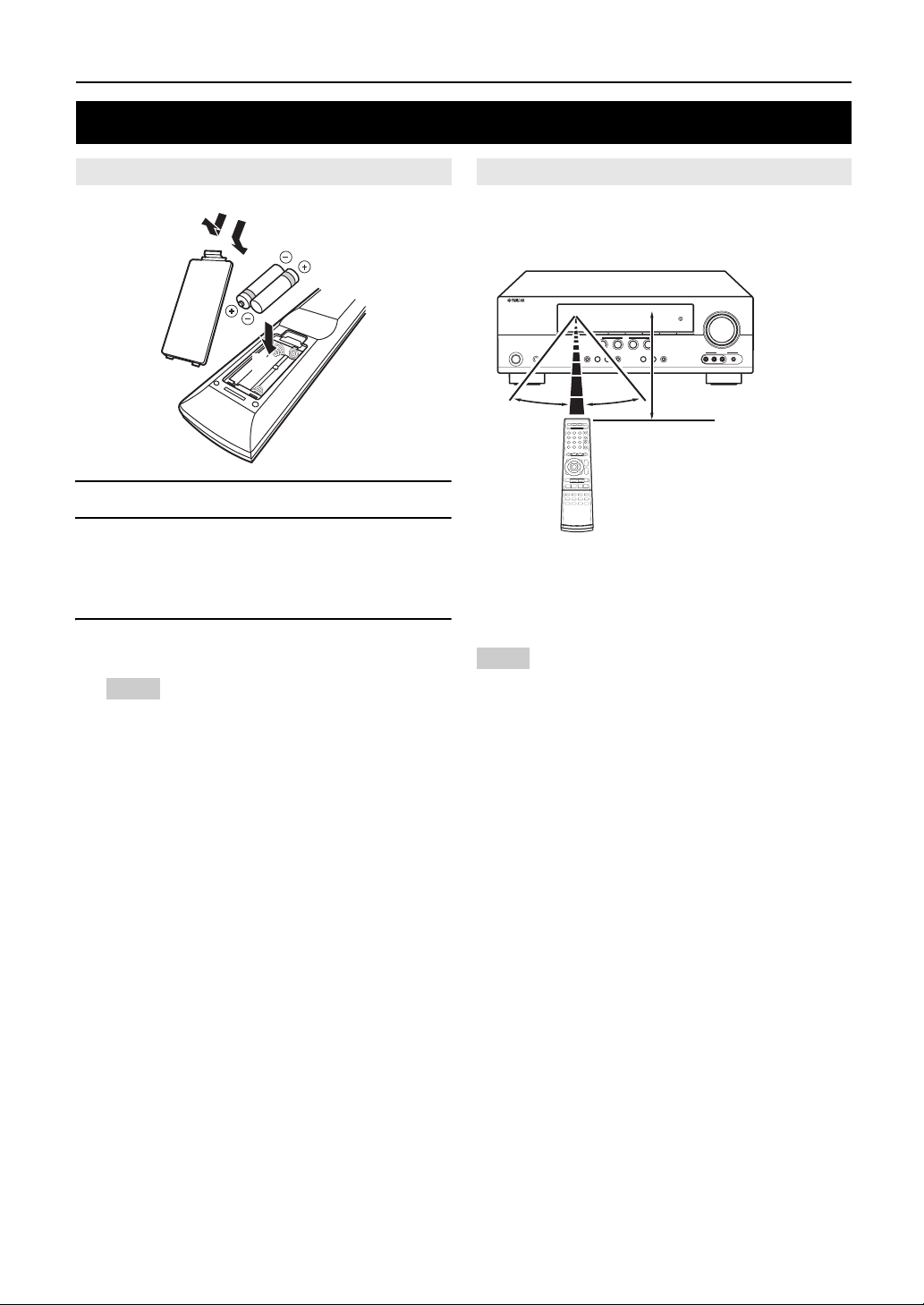
Installing batteries in the remote control
1
3
2
1 Take off the battery compartment cover.
2 Insert the four supplied batteries (AAA, R03,
UM-4) according to the polarity markings (+
and –) on the inside of the battery
compartment.
3 Snap the battery compartment cover back
into place.
Notes
• Change all of the batteries if you notice the following conditions:
– the operation range of the remote control decreases.
• Do not use old batteries together with new ones.
• Do not use different types of batteries (such as alkaline and
manganese batteries) together. Read the packaging carefully as
these different types of batteries may have the same shape and
color.
• If the batteries have leaked, dispose of them immediately. Avoid
touching the leaked material or letting it come into contact with
clothing, etc. Clean the battery compartment thoroughly before
installing new batteries.
• Do not throw away batteries with general house waste; dispose of
them correctly in accordance with your local regulations.
• If the remote control is without batteries for more than 2 minutes,
or if exhausted batteries remain in the remote control, the contents
of the memory may be cleared. When the memory is cleared, insert
new batteries and set up the remote control code.
Using the remote control
The remote control transmits a directional infrared ray.
Be sure to aim the remote control directly at the remote
control sensor on this unit during operation.
30º 30º
a Infrared window
Outputs infrared control signals. Aim this window at the
component you want to operate.
y
• To set the remote control codes for other components, see page 38.
Notes
• Do not spill water or other liquids on the remote control.
• Do not drop the remote control.
• Do not leave or store the remote control in the following types of
conditions:
– places of high humidity, such as near a bath
– places of high temperature, such as near a heater or stove
– places of extremely low temperatures
– dusty places
• To set the remote control codes for other components, see page 38.
Approximately 6 m (20 ft)
8 En
Connections
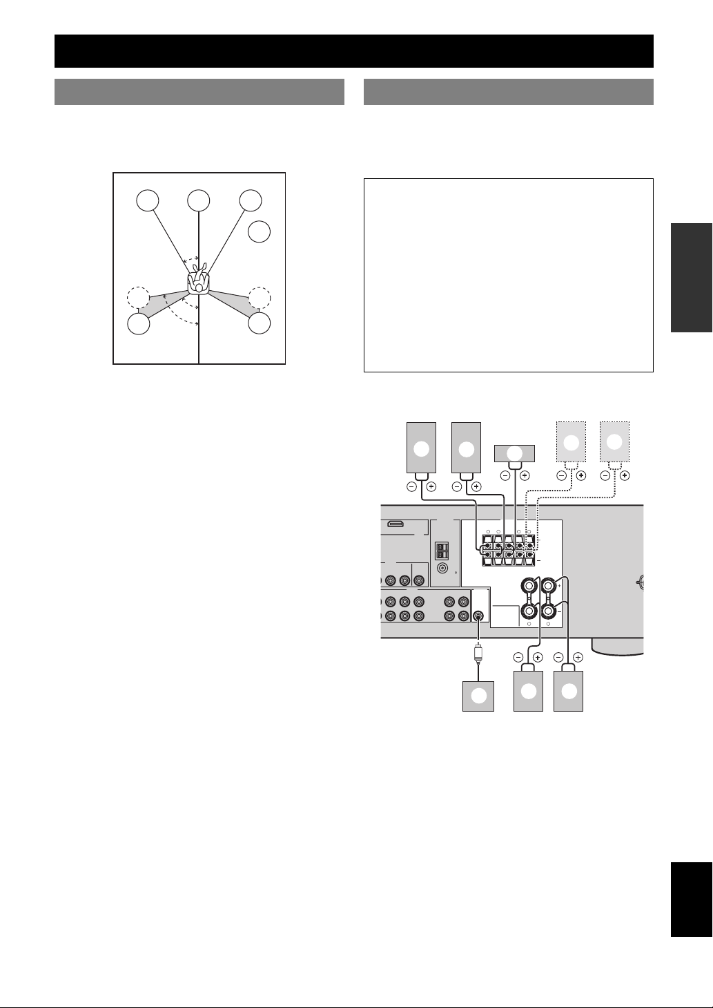
Placing speakers
The speaker layout below shows the speaker setting we
recommend. You can use it to enjoy CINEMA DSP and
multi-channel audio sources.
FL
SL
SL
C
30˚
60˚
80˚
Front left and right speakers (FL and FR)
The front speakers are used for the main source sound plus
effect sounds. Place these speakers at an equal distance
from the ideal listening position. The distance of each
speaker from each side of the video monitor should be the
same.
Center speaker (C)
The center speaker is for the center channel sounds
(dialog, vocals, etc.). If for some reason it is not practical
to use a center speaker, you can do without it. Best results,
however, are obtained with the full system.
Surround left and right speakers (SL and SR)
The surround speakers are used for effect and surround
sounds.
Subwoofer (SW)
The use of a subwoofer with a built-in amplifier, such as
the Yamaha Active Servo Processing Subwoofer System,
is effective not only for reinforcing bass frequencies from
any or all channels, but also for high fidelity sound
reproduction of the LFE (low-frequency effect) channel
included in Dolby Digital and DTS sources. The position
of the subwoofer is not so critical, because low bass
sounds are not highly directional. But it is better to place
the subwoofer near the front speakers. Turn it slightly
toward the center of the room to reduce wall reflections.
FR
SW
SR
SR
Connecting speakers
Be sure to connect the left channel (L), right channel (R),
“+” (red) and “–” (black) properly. If the connections are
faulty, this unit cannot reproduce the input sources
accurately.
Caution
• Use speakers with the specified impedance shown on
the rear panel of this unit.
• Before connecting the speakers, make sure that this
the AC power plug is disconnected from the AC wall
outlet.
• Do not let the bare speakers wires touch each other or
do not let them touch any metal part of this unit. This
could damage this unit and/or speakers.
• Use magnetically shielded speakers. If this type of
speaker still creates interference with the monitor,
place the speakers away from the monitor.
■ 5.1-channel speaker connection
c
DTV/CBL
HDMI
VIDEO
L
MONITOR
DVR
OUT
IN
OUT
AUDIO OUTPUT
L DVR CD
IN
OUT
ANTENNA
d
AM
GND
FM
75
UNBAL.
OUT
IN
MD/
(REC)
(PLAY)
CD-R
SURROUND CENTER FRONT B
SUB
WOOFER
h
e
SPEAKERS
a b
f
LRLR
LR
FRONT A
g
INTRODUCTION
PREPARATION
OPERATION
BASIC
OPERATION
ADVANCED
INFORMATION APPENDIX
ADDITIONAL
English
9 En

Connections
Speakers Jacks on this unit
a Front speaker (A) Right* FRONT A (R)
b Front speaker (A) Left* FRONT A (L)
c Surround speaker Right SURROUND (R)
d Surround speaker Left SURROUND (L)
e Center speaker CENTER
f Front speaker (B) Right* FRONT B (R)
g Front speaker (B) Left* FRONT B (L)
h Subwoofer SUBWOOFER
* You can select the front speaker set from Front speakers (A) and Front
speakers (B) by pressing CSPEAKERS repeatedly. See page 19 for
details.
■ Connect speaker cables to each speaker
■ Connecting to the FRONT A terminals
2
1
Red: positive (+)
Black: negative (–)
3
1 Loosen the knob.
2 Insert the bare end of the speaker wire into
the slit on the terminal.
3 Tighten the knob to secure the wire.
■ Connecting to the FRONT B, CENTER, and
SURROUND terminals
Red: positive (+)
Black: negative (–)
Cables are colored or shaped differently, perhaps with a
stripe, groove or ridge. Connect the striped (grooved, etc.)
cable to the “+” (red) terminals of your speaker. Connect
the plain cable to the “–” (black) terminals.
■ Before connecting to the SPEAKERS
terminal
A speaker cord is actually a pair of insulated cables
running side by side.
Remove approximately 10 mm (3/8”) of insulation
from the end of each speaker cable and then
twist the bare wires of the cable together to
prevent short circuits.
10 mm (3/8”)
1 Press down the tab.
2 Insert the bare end of the speaker wire into
the hole on the terminal.
3 Release the tab to secure the wire.
10 En

Connections
Connecting video components
Information on jacks and cable plugs
Audio jacks and cable plugs
AUDI O
L
(White) (Red) (Orange)
L
Left and right
analog audio
cable plugs
DIGITAL AUDIO
R
R
COAXIAL
C
Coaxial
digital audio
cable plug
AUDIO jacks
For conventional analog audio signals transmitted via left
and right analog audio cables. Connect red plugs to the
right jacks and white plugs to the left jacks.
COAXIAL jack
For digital audio signals transmitted via coaxial digital
audio cable.
OPTICAL jacks
For digital audio signals transmitted via optical digital
audio cables.
Notes
• You can use the digital jacks to input PCM, Dolby Digital, and DTS
bitstreams. All digital input jacks are compatible with digital signals with
up to 96 kHz of sampling frequency.
• This unit handles digital and analog signals independently. Thus audio
signals input at the digital jacks are not output at the analog AUDIO OUT
(REC) jack.
Video jacks and cable plugs
VIDEO
COMPONENT VIDEO
Y PBP
DIGITAL AUDIO
OPTICAL
O
Optical
digital
audio cable
plug
R
VIDEO jacks
For conventional composite video signals transmitted via
composite video cables.
COMPONENT VIDEO jacks
For component signals, separated into the luminance (Y)
and chrominance (P
B, PR) video signals transmitted on
separate wires of component video cables.
Video signal flow for MONITOR OUT
Output
(MONITOR OUT)
P
R
B
P
Y
COMPONENT
VIDEO
VIDEO
PR
P
Y
Input
B
Information on HDMI™
Audio signals input at the HDMI jack are not output
from any speaker terminals but output from the
connected video monitor. To enjoy the sound from
speakers connected to this unit,
– make an analog or digital connection besides the
HDMI connection (see page 13).
– mute the volume of the connected video monitor.
You can play back pictures by connecting your video
monitor and video source component to this unit using
HDMI connections.
At that time, audio/video signals output from the
connected component (such as DVD player etc.) are
output to the connected video monitor only when this unit
is turned on and set to the input source (DVD or DTV/
CBL).
Furthermore, available audio/video signals depend on the
specification of the connected video monitor. Refer to the
instruction manual of each connected component.
■ HDMI jack and cable plug
HDMI
HDMI cable plug
INTRODUCTION
PREPARATION
OPERATION
BASIC
OPERATION
ADVANCED
INFORMATION APPENDIX
ADDITIONAL
(Yellow) (Blue) (Red)(Green)
V
Composite
video cable
plug
Y
PB
Component
video cable
plugs
y
• We recommend using an HDMI cable shorter than 5 meters (16 feet)
with the HDMI logo printed on it.
• Use a conversion cable (HDMI jack ↔ DVI-D jack) to connect this unit
to other DVI components.
P
R
Using the AUDIO OUT REC jack
You can record the audio signal output at the AUDIO
OUT (REC) jack by using the recording components.
English
Note
• Check the copyright laws in your country to record from CDs, radio, etc.
Recording of copyrighted material may infringe copyright laws.
11 En
Connections
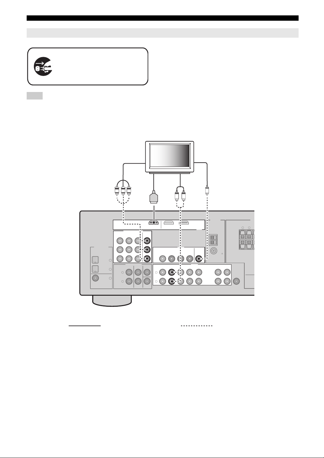
Connecting a TV monitor or projector
Make sure that this unit and other
components are unplugged from the
AC wall outlets.
Note
• If you turn off the video monitor connected to the HDMI OUT jack via a DVI connection, the connection may fail. In this case, the HDMI indicator
flashes irregularly.
TV
(or projector)
Component
video in
HDMI
in
PRPBY
Video
in
Audio
out
V
LR
HDMI
MONITOR
OUT
ANTENNA
AM
GND
FM
75
UNBAL.
OUTPUT
OUT
IN
MD/
(REC)
(PLAY)
CD-R
WOOFER
DIGITAL INPUT
OPTICAL
COAXIAL
CD
DTV/
CBL
DVD
DVD DTV/CBL DVR
P
R
P
B
Y
3
2
1
COMPONENT VIDEO
MULTI CH INPUT
FRONT CENTER
SURROUND
L
R
MONITOR
OUT
SUBWOOFER
L
R
DVDOUT DTV/CBL
VIDEO
DTV/CBL
DVD
DVD DTV/CBL DVR CD
DVR
IN
OUT
AUDIO
OUT
IN
Recommended connections Alternative connections
SUB
SURROUND C
LR
SP
12 En

Connecting other components
Connections
Connecting audio and video components
This unit has three types of audio jacks, two types of video jacks and HDMI jacks. You can choose the connection
method depending on the component to be connected.
■ Connecting example (connecting a DVD player)
DIGITAL INPUT
OPTICAL
COAXIAL
Coaxial out
CD
DTV/
CBL
DVD
P
R
P
B
Y
3
2
1
COMPONENT VIDEO
DVD DTV/CBL DVR
FRONT CENTER
SURROUND
L
R
C
PRPBY
MONITOR
OUT
SUBWOOFER
Component out
DTV/CBL
DVD
DTV/CBL DVR CD
DVD
L
R
R
L
DVDOUT DTV/CBL
VIDEO
DVR
IN
IN
Audio out
Video out
V
HDMI
MONITOR
OUT
AUDIOMULTI CH INPUT
OUT
HDMI out
ANTENNA
AM
GND
OUT
FM
75
UNBAL.
IN
MD/
(PLAY)
CD-R
S
OUTPUT
OUT
(REC)
SUB
WOOFER
INTRODUCTION
PREPARATION
OPERATION
BASIC
OPERATION
ADVANCED
Recommended connections Alternative connections
■ Jacks used for audio and video connections
Recommended connections are indicated by (*). When connecting a recording component, you need to make additional
connections for recording (signal transmission from this unit to the recording component).
y
• You can also use the VIDEO AUX jacks (see page 14) on the front panel
Make sure that this unit and other
components are unplugged from the
AC wall outlets.
Component Signal type Jacks on component Jacks on this unit
DVD player or Blu-ray
Disc player
Video HDMI out* HDMI (DVD)*
Component out COMPONENT VIDEO (DVD)
Video out (composite) VIDEO (DVD)
Audio Optical out* COAXIAL (DVD)*
Audio out (analog) AUDIO (DVD)
Set-top box Video HDMI out* HDMI (DTV/CBL)*
Component out COMPONENT VIDEO (DTV/CBL)
Video out (composite) VIDEO (DTV/CBL)
Audio Optical out* OPTICAL (DTV/CBL)*
Analog out (analog) AUDIO (DTV/CBL)
to connect an additional component.
• To confirm the positions of “jacks on this unit” in the following table,
refer to “Rear panel” in “Functional overview” on page 6.
INFORMATION APPENDIX
ADDITIONAL
English
13 En
Connections
Component Signal type Jacks on component Jacks on this unit
DVD r ecord er Video HDMI out* HDMI (DVR)*
Video out (composite) VIDEO (DVR IN)
Audio Audio out (analog)* AUDIO (IN (PLAY))*
Audio recording Audio in (analog)* AUDIO (OUT (REC))*
Video recording Video in (composite)* VIDEO (DVR OUT)*
CD player Audio Coaxial out* OPTICAL (CD)*
Audio out (analog) AUDIO (CD)
MD or CD recorder Audio Audio out (analog)* AUDIO (IN (PLAY))*
Audio recording Audio in (analog)* AUDIO (OUT (REC))*
Notes
• Be sure to make the same type of video connections as those made for your TV if the video conversion is disabled. For example, if you connected your
TV to the VIDEO MONITOR OUT jack of this unit, connect other components to the VIDEO jacks.
• Check the copyright laws in your country to record from CDs, radio, etc. Recording of copyrighted material may infringe copyright laws.
• To make a digital connection to a component other than the default one assigned to each DIGITAL INPUT or DIGITAL OUTPUT jack, configure the
“INPUT ASSIGN” setting (see page 33).
• Only analog audio signals output at AUDIO OUT (REC) jack can be recorded using the recording components. Therefore Digital signals input at the
DIGITAL INPUT jacks or analog signals input at MULTI CH INPUT jacks can be output at the analog AUDIO OUT (REC) jack for recording.
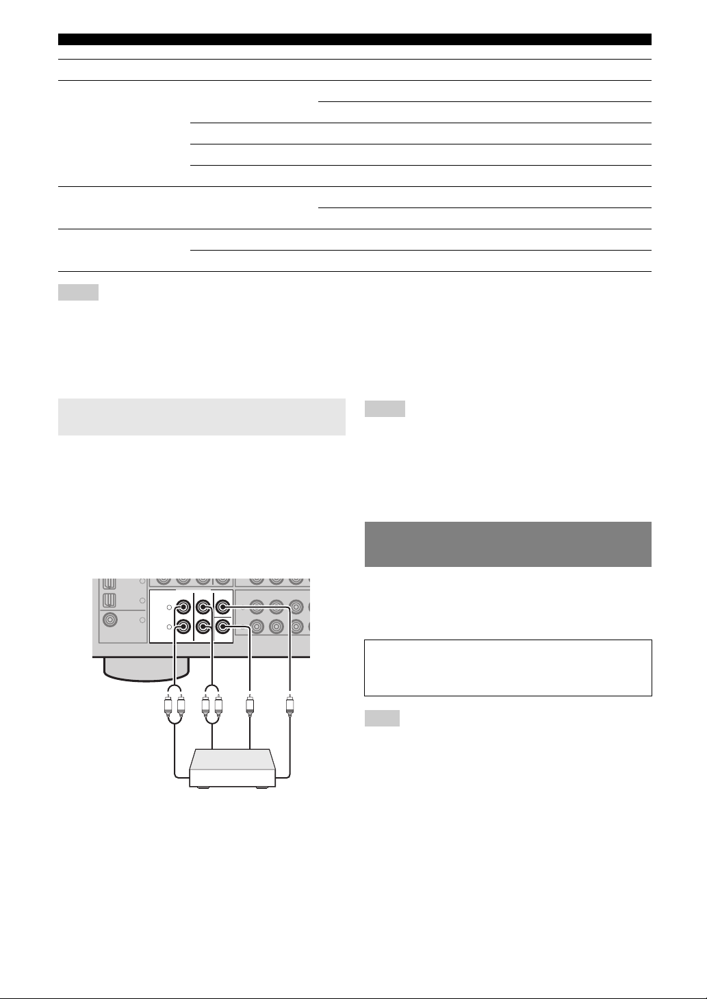
Connecting a multi-format player or an
external decoder
This unit is equipped with 6 additional input jacks
(FRONT L/R, SURROUND L/R, CENTER and
SUBWOOFER) for discrete multi-channel input from a
multi-format player, external decoder or sound processor.
Connect the output jacks on your multi-format player or
external decoder to the MULTI CH INPUT jacks. Be sure
to match the left and right output jacks to the left and right
input jacks for the front and surround channels.
CD
3
COAXIAL
MULTI CH INPUT
FRONT CENTER
DTV/
2
CBL
1
DVD
SURROUND
L
R
L
SUBWOOFER
Front out
R
R
L
Multi-format player or
external decoder
DTV/CBL DV
DVD
L
R
Surround out
IN
Subwoofer out
Center out
Notes
• When you select the component connected to the MULTI CH INPUT
jacks as the input source (see page 19), this unit automatically turns off
the digital sound field processor, and you cannot select sound field
programs.
• This unit does not redirect signals input at the MULTI CH INPUT jacks
to accommodate for missing speakers. We recommend that you connect a
5.1-channel speaker system before using this feature.
• The source connected to the MULTI CH INPUT jacks on this unit cannot
be recorded.
Using the VIDEO AUX jacks on the
front panel
Use the VIDEO AUX jacks on the front panel to connect a
game console or a video camera to this unit. To reproduce
the source signals input at these jacks, select “V-AUX” as
the input source.
Caution
Be sure to turn down the volume of this unit and other
components before making connections.
Note
• The audio signals input at the PORTABLE mini jack take priority over
the ones input at the AUDIO L/R jacks.
14 En
Connections
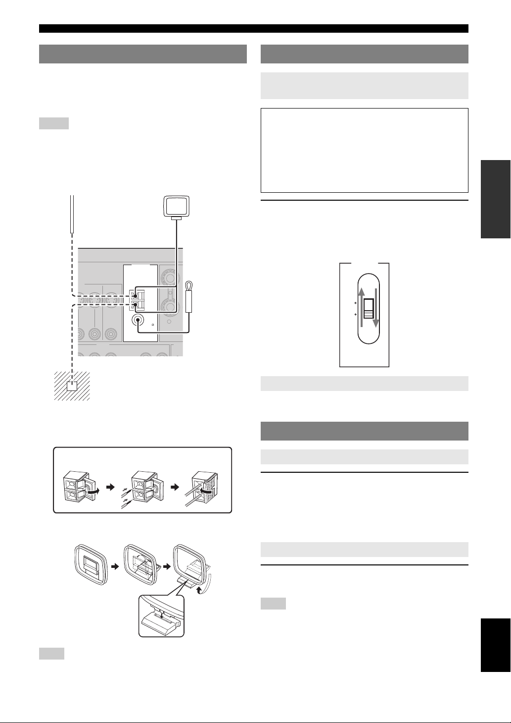
Connecting the FM and AM antennas
Both FM and AM indoor antennas are supplied with this
unit. In general, these antennas should provide sufficient
signal strength. Connect each antenna correctly to the
designated terminals.
Notes
• The AM loop antenna should be placed away from this unit.
• A properly installed outdoor antenna provides clearer reception than an
indoor one. If you experience poor reception quality, install an outdoor
antenna. Consult the nearest authorized Yamaha dealer or service center
about outdoor antennas.
• The AM loop antenna should always be connected, even if an outdoor
AM antenna is connected to this unit.
Outdoor AM antenna
Use a 5 to 10 m (16 to 32 ft)
of vinyl-covered wire
extended outdoors from a
window.
ANTENNA
EO
DVR
MONITOR
N OUT
OUT
AUDIO OUT
DVR
N
CD
OUT
(PLAY)
UNBAL.
IN
AM
GND
FM
75
CD-R
OUT
MD/
(REC)
AM loop
antenna
(supplied)
Indoor FM
antenna
(supplied)
R
SURR
Connecting the power cable
VOLTAGE SELECTOR (Asia and General
model only)
Caution
The VOLTAGE SELECTOR on the rear panel of this
unit must be set for your local voltage BEFORE
plugging the power cable into the AC wall outlet.
Improper setting of the VOLTAGE SELECTOR may
cause damage to this unit and create a potential fire
hazard.
Select the switch position (upper or lower)
according to your local voltage using a straight
slot screwdriver.
Voltages are 110-120/220-240 V AC, 50/60 Hz.
VOLTAGE
SELECTOR
110V120V
220V240V
INTRODUCTION
PREPARATION
OPERATION
BASIC
OPERATION
ADVANCED
Ground
For maximum safety and minimum
interference, connect the antenna GND
terminal to a good earth ground. A good earth
ground is a metal stake driven into moist earth.
Connecting the wire of the AM loop antenna
Open the
lever
Insert Close the
lever
Assembling the supplied AM loop antenna
Note
• The types of the supplied AM loop antenna is different depending on the
models.
Connecting the AC power cable
Once all connections are complete, plug the power cable
into the AC wall outlet.
Turning on and off the power
Turning on this unit
Press ASTANDBY/ON (or dPOWER) to turn on
this unit.
y
• When you turn on this unit, there will be a 4 to 5-second delay before this
unit can reproduce sound.
Set this unit to the standby mode
Press ASTANDBY/ON (or cSTANDBY) to turn
off this unit.
Note
• In the standby mode, this unit consumes a small amount of power in
order to receive infrared signals from the remote control.
15 En
INFORMATION APPENDIX
ADDITIONAL
English

Optimizing the speaker setting for your listening room (YPAO)
This unit has the Yamaha Parametric Acoustic Optimizer (YPAO). With the YPAO, this unit automatically adjusts output
characteristics of your speakers based on speaker positions, speaker performances, and acoustic characteristics of the
room. We recommend that you first adjust the output characteristics with the YPAO when you use this unit.
Notes
• Be advised that it is normal for loud test tones to be
output during the “AUTO SETUP” procedure. Do not
allow small children to enter the room during the
procedure.
• To achieve the best results, make sure that the room
is as quiet as possible while the “AUTO SETUP”
procedure is in progress. If there is too much ambient
noise, the results may not be satisfactory.
Using AUTO SETUP
y
• Initial settings are indicated by (*) in the following each parameter.
1 Make sure of the following check points.
Before starting the automatic setup, check the
following check points.
• All speakers and subwoofer are connected
appropriately.
• Headphones are disconnected from this unit.
• This unit is turned on.
• The connected subwoofer is tuned on and the
volume level is set to about half way (or slightly
less).
• FRONT A speakers are selected as the front
speaker system (see page 19).
• The room is sufficiently quiet.
• The crossover frequency control of the connected
subwoofer is set to the maximum.
VOLUME
MIN
MAX
Controls of a subwoofer (example)
2 Connect the supplied optimizer microphone
to the OPTIMIZER MIC jack on the front
panel.
“SETUP•••••AUTO” appears on the front panel
display.
CROSSOVER
HIGH CUT
MIN MAX
3 Place the optimizer microphone at your
normal listening position on a flat level
surface with the omni-directional
microphone heading upward.
Optimizer microphone
y
• We recommend that you use a tripod (etc.) to affix the optimizer
microphone at the same height as your ears would be when you are
seated in your listening position. You can use the attached screw of
a tripod (etc.) to fix the optimizer microphone to the tripod (etc.).
4 Press ll / h to select “AUTO.”
Choice Function
AUTO* Automatically runs the entire “AUTO
SETUP” procedure.
RELOAD Reloads the last “AUTO SETUP” settings and
overrides the previous settings.
UNDO Undoes the last “AUTO SETUP” settings and
restores the previous settings.
DEFAULT Resets the “AUTO SETUP” parameters to the
initial factory settings.
Note
• “RELOAD” or “UNDO” is available only when you have
previously run “AUTO SETUP” and confirmed the results.
5 Press lENTER to start the setup
procedure.
This unit starts the automatic setup procedure. Loud
test tones are output from each speaker during the
audio setup procedure. After all settings
(“INITIALIZING,” “WIRING/LEVEL,”
“DISTANCE,” “SIZE”) are sequentially completed,
“FINISH” appears on the front panel display.
y
• To cancel the automatic setup, press lk.
16 En

Optimizing the speaker setting for your listening room (YPAO)
Notes
• During the automatic setup procedure, do not perform any
operation on this unit.
• We recommend that you get out of the room while this unit is in the
auto setup procedure. It takes approximately 3 minutes for this unit
to complete the auto setup procedure.
6 When all measurements are completed
successfully, “FINISH” appears on the front
panel display.
The result of the automatic setup for each speaker
appears in order on the front panel display.
The distance between the speaker
and the listening position
FL: 3.3m +2
Speaker
FL/FR: Front left/right
C: Center
SL/SR: Surround left/right
SW: Subwoofer
y
• To display the result of the automatic setup again, press lk / n
repeatedly.
Notes
• If you select “RELOAD” in step 4, no test tones are output.
• If an error occurs during the “AUTO:CHECK” procedure, the
setup procedure is canceled and an error screen appears. For
details, see “If an error screen appears” on page 17.
• When this unit detects potential problems during the “AUTO
SETUP” procedure, “WARNING” and the warning messages
appear after this unit displays the result of the automatic setup. For
details, refer to the “AUTO SETUP” section in “Troubleshooting”
on page 43.
• The distance measurement result may be longer than the actual
distance depending on the characteristics of your subwoofer.
7 Press ll / h to select “SET” or “CANCEL.”
The result of the
adjustment of the
volume level
■ If an error screen appears
If this unit detects the potential problems, an error
message appears on the front panel display during the
automatic setup.
For details about each error message, see the “AUTO
SETUP” section in “Troubleshooting” on page 43.
After a few seconds later, the following choices appear.
Press ll / h to select “RETRY” or “EXIT” and then
press lENTER.
Choice Function
RETRY* Starts the “AUTO SETUP” again.
EXIT Exits from the “AUTO SETUP” procedure.
■ If “WARNING” appears
When this unit detects potential problems during the
automatic setup procedure, “WARNING” appears on the
front panel display after result of each speaker. Check the
warning messages to correct your speaker settings.
Note
• Warnings differ from errors in that warnings do not cancel the automatic
setup procedure.
Press ln to display the detailed information
about the warning.
The detailed information about the warning is displayed
and the indicators of inapplicable speakers blink on the
front panel display.
LFE
LCR
PHASE REVERSED
y
• For details about each warning message, see the “AUTO SETUP” section
in “Troubleshooting” on page 43.
SL SR
Flashes
INTRODUCTION
PREPARATION
OPERATION
BASIC
OPERATION
ADVANCED
INFORMATION APPENDIX
ADDITIONAL
Choice Function
SET* Confirms the “AUTO SETUP” results.
CANCEL Cancels the “AUTO SETUP” results.
8 Press lENTER to confirm your selection.
“AUTO SETUP” appears on the front panel display.
9 Press kMENU to exit from “SET MENU.”
10 Disconnect the optimizer microphone from
this unit.
The optimizer microphone is sensitive to heat. Keep it
away from direct sunlight and do not place it on top
of this unit.
y
• If you change speakers, speaker positions, or the layout of your
listening environment, run “AUTO SETUP” again to recalibrate
your system.
• When you want to check the result of the automatic setup in detail
or manually adjust the parameters, use “MANUAL SETUP” (see
page 31).
English
17 En

BASIC OPERATION
Playback
Caution
Extreme caution should be exercised when you play
back CDs encoded in DTS. If you play back a CD
encoded in DTS on a DTS-incompatible CD player,
you will only hear some unwanted noise that may
damage your speakers. Check whether your CD player
supports CDs encoded in DTS. Also, check the sound
output level of your CD player before you play back a
CD encoded in DTS.
Basic procedure
1 Turn on e x t e r na l c o mponents (TV, DVD
player, etc.) connected to this unit.
2 Press CSPEAKERS repeatedly to select the
front speakers you want to use.
The respective speaker indicators lights up on the
front panel display.
3 Press NINPUT l / h repeatedly (or press
one of the input selector buttons (f)) to
select the desired input source.
The name of the currently selected input source
appears on the front panel display for a few seconds.
5 Rotate PVOLUME (or press mVOLUME +/–)
to adjust the volume to the desired output
level.
y
• See page 20 to adjust the level of each speaker.
• This does not affect the AUDIO OUT (REC) level.
• You can set the initial volume level and maximum volume level
(see page 33).
6 Press LPROGRAM l / h (or press hAMP
and then qPROG l / h) repeatedly to select
the desired sound field program.
The name of the selected sound field program appears
on the front panel display.
See page 22 for details about sound field programs.
Available input source
DVR DVD CD
V-AUX DTV/CBL
MD/CD-R
TUNER
INPUT:DVD
Currently selected input source
4 Start playback on the selected component or
select a broadcast station.
Notes
• Refer to the operating instructions for the source component.
• See page 28 for details about FM or AM tuning instructions.
y
• To adjust the level of each speaker, see page 20.
Movie Dramatic
Currently selected surround field program
Notes
• Choose a sound field program based on your listening preference, not
merely on the name of the program.
• When you select an input source, this unit automatically selects the last
sound field program used with the corresponding input source.
• Sound field programs cannot be selected when the component connected
to the MULTI CH INPUT jacks is selected as the input source (see
page 19).
• When PCM signals with a sampling frequency higher than 48 kHz are
input, this unit is automatically set to the “STRAIGHT” mode (see
page 27).
• To display information about the currently selected input source on the
front panel display, see page 21 for details.
18 En

Playback
Guide to contents
When you want… See page
Adjust the tonal quality of the front
speakers
Edit parameters of sound field
programs
Enjoy the sources which have wide
dynamic range at night
Use headphones 20
Select a decoder to play back
sources with
Set this unit to the standby mode
automatically
20
27
20
27
21
Additional operations
Using input setting features
Use the following features to select input jack or input
source.
■ Selecting the front speaker set
■ Selecting the component connected to the
MULTI CH INPUT jacks as the input source
Use this feature to select the component connected to the
MULTI CH INPUT jacks (see page 14) as the input
source.
Press NINPUT l / h repeatedly (or press
hAMP and then press vMULTI CH IN) to
select “MULTI CH.”
“MULTI CH” appears on the front panel display.
y
• You can configure the multi channel input settings in “MULTI CH” (see
page 34).
Notes
• Sound field programs, or the night listening mode, etc. cannot be selected
when “MULTI CH” is selected as the input source.
• When headphones are used, signals are output only from the front left
and right channels.
■ Selecting audio input jacks (AUDIO SELECT)
Use this feature (audio input jack select) to switch the
input jack assigned to an input source when two or more
jacks are assigned to an input source.
y
• We recommend that you set the audio input jack select to “AUTO” in
most cases.
• You can adjust the default audio input jack select of this unit by using
“AUDIO SELECT” in “OPTION MENU” (see page 35).
INTRODUCTION
PREPARATION
OPERATION
BASIC
Press CSPEAKERS repeatedly change the
active front speaker set that is connected to the
FRONT A or FRONT B speaker terminals or turn
off the front speakers.
The active front speaker set changes as follows:
FRONT A FRONT B
OFF
Note
• Turn off the volume level of this unit before you switch the front speaker
setting.
■ Using the Zone B feature
When you set “FRONT B” to “ZONE B” (see page 31),
you can use the speakers connected to FRONT B speaker
terminals in another room (Zone B).
Press CSPEAKERS on the front panel
repeatedly to turn on or off the Zone B speakers.
When you activate the Zone B speakers, all the speakers in
the main room are muted.
Notes
• You cannot activate both the main room and Zone B speakers
simultaneously.
• If you select CINEMA DSP sound field program and activate the Zone B
speakers, Virtual CINEMA DSP is activated automatically (see page 27).
1 Press NINPUT l / h repeatedly (or press
one of the input selector buttons (f)) to
select the desired input source.
2 Press hAMP and then wAUDIO SEL
repeatedly to select the desired Audio input
jack select setting.
DVR DVD CD
V-AUX DTV/CBL
MD/CD-R
TUNER
A.SEL:AUTO
Audio input jack select setting
Choice Function
AUTO Automatically selects input signals in
the following order:
(1) Digital signals
(2) Analog signals
ANALOG Selects only analog signals. If no
analog signals are input, no sound is
output.
y
• You can configure the audio input jack select setting in “AUDIO
SELECT.”
Note
• This feature is not available if no digital input jack is assigned to
the selected input source in “INPUT ASSIGN” (see page 33).
OPERATION
ADVANCED
INFORMATION APPENDIX
ADDITIONAL
English
19 En

Playback
Using audio features
Use the following features to adjust the audio output or
speaker level.
■ Muting the audio output
Press eMUTE on the remote control to mute the
audio output. Press eMUTE again to resume
the audio output.
y
• You can also rotate PVOLUME (or press mVOLUME +/–) to
resume the audio output.
• You can configure the muting level by using “MUTE TYP.” in “SOUND
MENU” (see page 33).
• The MUTE indicator flashes on the front panel display when the audio
output is muted and disappears from the front panel display when the
audio output is resumed.
■ Adjusting the tonal quality
Use this feature to adjust the balance of bass and treble for
the front left and right speaker channels.
Press KTONE CONTROL repeatedly to select
“BASS” or “TREBLE” and then press
LPROGRAM l / h to adjust the corresponding
frequency response level.
Control range: –10 dB to +10 dB
Each choice is defined as follows.
Choice Function
BASS Adjusts the low-frequency response.
TREBLE Adjusts the high-frequency response.
y
• Once you press jBAND LEVEL TITLE on the remote
control, you can also select the speaker by pressing lk / n.
• The available speaker channels differ depending on the speaker
settings.
2 Press ll / h on the remote control (or
press FPRESET/TUNING l / h) to adjust
the speaker output level.
Control range: –10.0 dB to +10.0 dB
Using optional features
Use the following features to utilize various useful
functions equipped on this unit.
y
• Initial settings are indicated by (*) in this following each parameter.
■ Using your headphones
Connect a pair of headphones with a stereo
analog audio cable plug to the PHONES jack on
the front panel.
y
• When you select a sound field program, SILENT CINEMA mode is
automatically activated (see page 27).
Notes
• When you connect headphones, no signals are output at the speaker
terminals.
• All Dolby Digital and DTS audio signals are mixed down to the left and
right headphone channels.
■ Selecting the night listening mode
The night listening modes are designed to improve
listenability at lower volumes or at night.
Notes
• Speaker and headphone adjustments are stored independently.
• If you increase or decrease the high-frequency or low-frequency sound to
an extreme level, the tonal quality of the surround speakers may not
match that of the front left and right speakers.
• This does not affect recorded material.
■ Adjusting the speaker level
You can adjust the output level of each speaker while
listening to a music source. This is also possible when
playing sources input at the MULTI CH INPUT jacks.
Note
• This operation will override the level adjustment made in “SP LEVEL”
(see page 32).
1 Press hAMP and then press jBAND
LEVEL TITLE repeatedly to select the
speaker you want to adjust.
Choice Description
FRONT L Front left speaker
FRONT R Front right speaker
CENTER Center speaker
SWFR Subwoofer
SUR.L Surround left speaker
SUR.R Surround right speaker
1 Press ONIGHT (or press hAMP and then
uNIGHT) repeatedly to select
“NIGHT:CINEMA” or “NIGHT:MUSIC.”
Each choice is defined as follows.
Choice Function
NIGHT:CINEMA Narrows the dynamic range of film
soundtracks and makes dialog easier to
hear at lower volumes.
NIGHT:MUSIC Preserves ease-of-listening for all
sounds.
NIGHT OFF Disables this feature.
y
• When a night listening mode is selected, the NIGHT indicator
lights up on the front panel display.
20 En
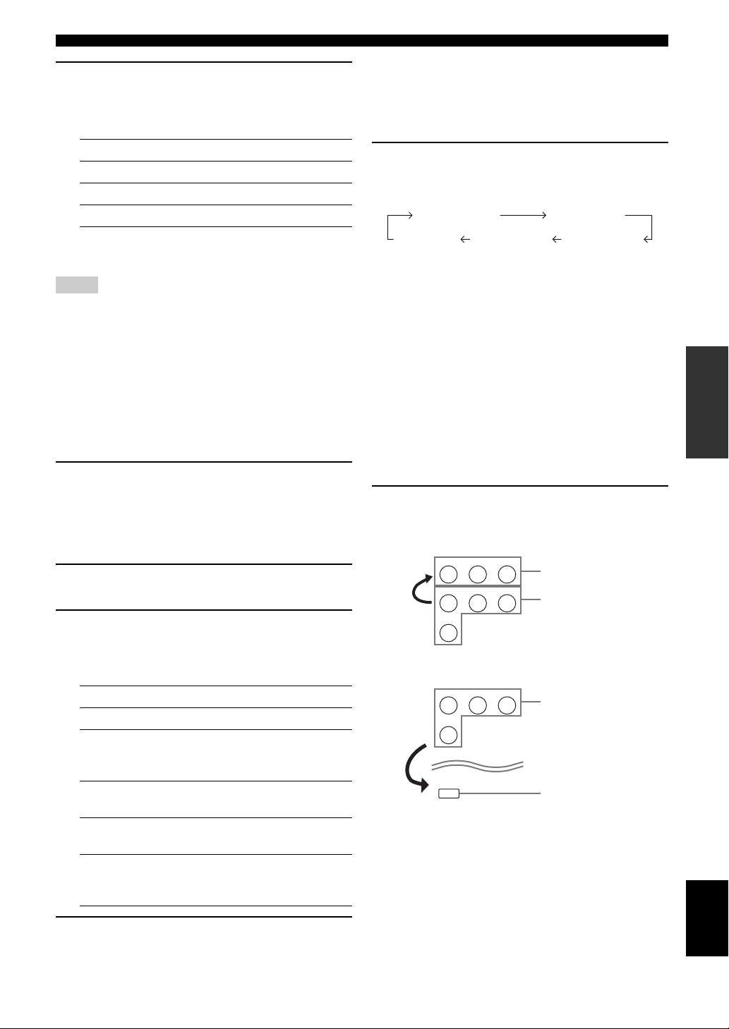
Playback
2 Press ll / h to adjust the effect level while
“NIGHT:CINEMA” or “NIGHT:MUSIC” is
displayed on the front panel display.
Each choice is defined as follows.
Choice Function
MIN Slightly lowers the effect level.
MID* Moderately lowers the effect level.
MAX Considerably lowers the effect level.
y
• “NIGHT:CINEMA” and “NIGHT:MUSIC” adjustments are stored
independently.
Notes
• You cannot use the night listening modes in the following cases:
– when the component connected to the MULTI CH INPUT jacks is
selected as the input source.
– when headphones are connected to the PHONES jack.
– when the sampling frequency of the input sources are higher than 48
kHz.
• The effect of night listening modes may vary depending on the input
source and surround sound settings you use.
■ Displaying the input source information
(SIGNAL INFO)
You can display the format, sampling frequency, channel,
bit rate and flag data of the current input signal.
1 Press hAMP and then press kMENU on
the remote control.
“AUTO SETUP” appears on the front panel display.
;AUTO SETUP
2 Press lk / n repeatedly to select “SIGNAL
INFO” and then press lENTER.
3 Press lk / n to switch the displayed
information.
The following information about the input source
appears on the front panel display.
Choice Description
FORMAT Signal format.
SAMPLING The number of samples per second
taken from a continuous signal to
make discrete signals.
CHANNEL The number of source channels in the
input signal (front/surround/LFE).
BITRATE The number of bits passing a given
point per second.
FLAG Flag data encoded in DTS, Dolby
Digital, or PCM signals that cue this
unit to automatically switch decoders.
■ Using the sleep timer
Use this feature to automatically set this unit to the
standby mode after a certain amount of time. The sleep
timer is useful when you are going to sleep while this unit
is playing or recording from a source.
Press hAMP and then press xSLEEP
repeatedly to set the amount of time.
The sleep timer setting changes as follows.
SLEEP 120min SLEEP 90min
SLEEP 60minSLEEP 30minSLEEP OFF
Once the sleep timer is set, the SLEEP indicator lights up
on the front panel display, and the display returns to the
selected sound field program.
To cancel the sleep timer
Press xSLEEP on the remote control repeatedly to
select “SLEEP OFF.”
y
• If you set the main zone to the standby mode, the sleep timer is
automatically canceled.
■ Playing video sources in the background
You can combine a video image from a video source with
sound from an audio source. For example, you can enjoy
listening to classical music while viewing beautiful
scenery from the video source on the video monitor.
Press the input selector buttons (f) on the
remote control to select a video source and then
an audio source.
CD MD/CD-R TUNER
DVD
DTV/CBL DVR
DVD
V-AU X
DVD
DTV/CBL DVR
DVD
V-AU X
MULTI CH IN
9
Audio sources
Video sources
Video sources
Audio sources
INTRODUCTION
PREPARATION
OPERATION
BASIC
OPERATION
ADVANCED
INFORMATION APPENDIX
ADDITIONAL
English
4 Press kMENU on the remote control again
to exit from “SET MENU.”
21 En
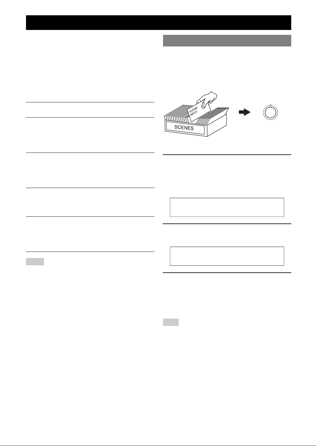
Selecting the SCENE templates
Just by pressing one SCENE button, you can recall your
favorite input source and sound field program according to
the SCENE template that has been assigned to the SCENE
button. The SCENE templates are built combinations of
input sources and sound field programs.
This unit is equipped with 12 preset SCENE templates for
various situations. The following SCENE templates are
assigned to respective SCENE buttons in the default
settings.
Default SCENE
button
SCENE 1
SCENE 2
SCENE 3
SCENE 4
The name of the SCENE template and
its description
DVD Movie Viewing
– input source: DVD
– sound field program: STRAIGHT
For when you want to enjoy a DVD
playback.
Music Disc Listening
– input source: DVD
– sound field program: 2ch Stereo
For when you want to listen to a music disc
from the connected DVD player.
TV Viewing *1
– input source: DTV/CBL
– sound field program: STRAIGHT
For when you want to watch a TV program.
Radio Listening *2, *3, *4
– input source: TUNER
– sound field program: Music Enh. 5ch
For when you want to listen to a music
program from the FM radio station.
Selecting the desired SCENE template
If you want to use other SCENE templates, you can select
the desired SCENE templates from the SCENE template
library and assign the templates to the selected SCENE
buttons on the front panel and the remote control.
Select the desired SCENE template
1
Assign the
SCENE template
to the SCENE
SCENE template library
(Image)
button
1 Press and hold the desired JSCENE (or
iSCENE) button for 3 seconds.
The MEMORY indicator on the front panel starts to
flash, and the name of currently assigned SCENE
template appears on the front panel display.
DVD Movie View
2 Press NINPUT l / h (or press hAMP and
then ll / h) to select the desired template.
Notes
*1 You must connect a cable TV or a satellite tuner to this unit in advance.
See page 13 for details.
*2 You need to connect the supplied FM and AM antennas to this unit in
advance. See page 15 for details.
*3 You have to tune into the desired radio station. See pages 28 to 29 for
the tuning information.
*4 To achieve the best possible reception, orient the connected AM loop
antenna, or adjust the position of the end of the indoor FM antenna.
22 En
DVD Viewing
3 Press the JSCENE (or iSCENE) button
again to confirm the selection.
The MEMORY indicator stops flashing and the select
SCENE template is assigned to the button.
y
• To cancel the procedure, press hAMP and then nRETURN.
Note
• Once the desired SCENE templates are assigned to the corresponding
SCENE buttons, you may need to set the input source of the SCENE
template on the remote control. See page 25 for details.

Selecting the SCENE templates
Which SCENE template would you like to select?
The following tables indicate preset SCENE template descriptions. Select the corresponding SCENE templates for the
desired source. The illustrations of the SCENE button in the following table indicate that the SCENE templates in those
cells are assigned to the SCENE buttons, respectively.
You can also create your original SCENE templates by editing the preset SCENE templates. See page 24 for details.
■ Video sources (DVD video, Recorded video)
SCENE template Input source Playback mode Features
DVD Viewing DVD STRAIGHT
1
DVD Movie Viewing DVD Movie Dramatic
DVD Live Viewing DVD Pop/Rock
DVR Viewing DVR Movie Dramatic
■ Music discs (CD, SA-CD or DVD-Audio)
SCENE template Input source Playback mode Features
2
Music Disc Listening DVD 2ch Stereo
Disc Listening DVD 5ch Stereo
CD Listening CD 5ch Stereo
CD Music Listening CD 2ch Stereo
Select this SCENE template when you play back
general contents on your DVD player.
Select this SCENE template when you play back
movies on your DVD player.
Select this SCENE template when you enjoy music
live video on your DVD player.
Select this SCENE template when you play back
movies on your digital video recorder.
Select this SCENE template when you play back
music discs on your DVD player.
Select this SCENE template when you play back
music sources as the back ground music on your
DVD player.
Select this SCENE template when you play back
music source as the back ground music on your CD
player.
Select this SCENE template when you play back
music discs on your CD player.
INTRODUCTION
PREPARATION
OPERATION
BASIC
OPERATION
ADVANCED
■ Radio programs
SCENE template Input source Playback mode Features
4
Radio Listening TUNER Music Enh. 5ch
■ TV programs
SCENE template Input source Playback mode Features
3
TV Viewing DTV/CBL STRAIGHT
TV Sports Viewing DTV/CBL TV Sports
■ Video games
SCENE template Input source Playback mode Features
Game Playing V-AUX Game
Select this SCENE template when you enjoy FM or
AM radio programs.
Select this SCENE template when you enjoy TV
programs.
Select this SCENE template when you enjoy sports
programs on TV.
Select this SCENE template when you play video
games.
23 En
INFORMATION APPENDIX
ADDITIONAL
English

Selecting the SCENE templates
Creating your original SCENE
templates
You can create your original SCENE templates for each
SCENE button. Refer to the preset 12 SCENE templates
to create the original SCENE templates.
Customizing the preset SCENE templates
Use this feature to customize the preset SCENE templates.
Select the desired SCENE
template
SCENE template library
(Image)
1 Press and hold the desired iSCENE button
for 3 seconds and then press hAMP.
The MEMORY indicator on the front panel starts to
flash.
1
3 seconds
Create an original SCENE
template
: DVD
INPUT
: DVD Viewing
SCENE
1
Assign the SCENE
template to the SCENE
button
AMP
SCENE : DVD Viewing
2 Press lk / n to select the desired parameter
of the SCENE template and then ll / h to
select the desired value of the selected
parameter.
You can adjust the following parameters for a SCENE
template:
• The input source component
• The active sound field programs or STRAIGHT
mode
• The night listening mode setting (see page 20)
– SYSTEM: Keeps the current night listening
mode.
– CINEMA: Sets the night listening mode to the
CINEMA mode.
– MUSIC: Sets the night listening mode to the
MUSIC mode.
3 Press the iSCENE button again to confirm
the edit.
1
y
• An asterisk mark (*) appears by the name of the original SCENE
template.
• To cancel the procedure, press hAMP and then nRETURN.
Notes
• After changing the assignment of the SCENE template to the iSCENE
buttons, you may need to set the input source of the SCENE template on
the remote control. See page 25 for details.
• You can create a customized SCENE template for each iSCENE
button, and if you create another customized SCENE template, this unit
overwrites the old customized SCENE template with the new one.
• The customized SCENE template is only available for the assigned
iSCENE button.
Note
• When the SCENE template you want to customize is not assigned
to any of the iSCENE button, press ll / h repeatedly to
recall the desired SCENE template (see page 22).
24 En

Using remote control on the SCENE
feature
Controlling the input source components
in the SCENE mode
You can operate both this unit and the input source
component by using the remote control. You must set the
appropriate remote control code for each input source in
advance (see page 38).
1 Press the desired iSCENE button on the
remote control.
2 Press the desired buttons in the * area below
to control the input source component of the
selected SCENE template.
Selecting the SCENE templates
INTRODUCTION
PREPARATION
POWER
STANDBY
POWER
POWER
AVTV
A B C
MUTE
CD MD/CD-R TUNER
DVD
V-AUX
AMP
*
BAND LEVEL
TITLE
RETURN
REC
l PROG h
STRAIGHT
MULTI CH IN AUDIO SEL
DTV/CBL DVR
D E
TV INPUT
SCENE
ENTER
65
TV MUTE
ENHANCER
NIGHT
TV CH
TV VOL
SCENE buttons
4321
VOLUME
MENU
DISPLAY
SUR. DECODE
4321
8
SLEEP
ENT
10709
Note
• These buttons control the input source component. See page 36 for
details of the function of each button.
Setting input source of the customized
SCENE template on the remote control
If you customize the input source of the selected SCENE
template, you must set the input source of the SCENE
template on the remote control to operate the input source
component correctly.
OPERATION
BASIC
OPERATION
ADVANCED
INFORMATION APPENDIX
ADDITIONAL
Press and hold the iSCENE button and the
desired input selector button (f) for 3 seconds.
y
• Press the iSCENE button again to operate the input source
component.
English
25 En

Sound field programs
This unit is equipped with a variety of precise digital
decoders that allow you to enjoy multi-channel playback
from almost any stereo or multi-channel sound source.
This unit is also equipped with a Yamaha digital sound
field processing (DSP) chip containing several sound field
programs which you can use to enhance your playback
experience.
Selecting sound field programs
Press LPROGRAM l / h (or press hAMP and
then press qPROG l / h repeatedly).
Notes
• When you select an input source, this unit automatically selects the last
sound field program used with corresponding input source.
• Sound field programs cannot be selected when the component connected
to the MULTI CH INPUT jacks is selected as the input source (see
page 19).
• When PCM signals with a sampling frequency higher than 48 kHz are
input, this unit is automatically set to the “STRAIGHT” mode (see
page 27).
y
• Choose a sound field program based on your listening preference, not
merely on the name of the program itself.
• You can select “Music Enh. 2ch” and “Music Enh. 5ch” by pressing
rENHANCER repeatedly.
The name of the selected sound field program appears on
the front panel display and on the OSD.
Sound field program descriptions
y
• Select a sound field program based on your listening preference, not merely on the name of the program, etc.
• The available sound field parameters differ depending on the settings of the speakers.
Category Program Features
Pop/Rock CINEMA DSP processing. This program presents an image of pop, rock, or jazz live concert. The
sound field reproduces the spaciousness of a massive pavilion with an emphasis on the vividness of
vocals on the stage and solo instruments and the beats of rhythm instruments.
MUSIC
ENTERTAIN
MOVIE
STEREO
ENHANCER
Hall CINEMA DSP processing. This sound field is suitable for classic and orchestral music. The
program uses data collected in a large concert hall in Munich. You can enjoy delicate and beautiful
reverberation and a majestic atmosphere.
Jazz CINEMA DSP processing. The sound field is suitable for jazz and fusion music.
It uses data collected in a famous jazz club in New York. You can enjoy clear reverberation.
Game CINEMA DSP processing. You can enjoy dynamic and thrilling sound effects as you play games.
The program lets you feel the depth and three-dimensional surrounding sounds of the field where
you are playing, and offers cinema-like surrounding sound effects for the scenes of movies.
TV Sports CINEMA DSP processing. You can enjoy sports relays broadcast in stereo and variety shows with
a live sound environment. For sports relays, the voices of commentators and announcers come
clearly from the center; the cheers and atmosphere in the stadium spread around within a
comfortable range, and you can feel like as if you are in the stadium.
Movie Spacious CINEMA DSP processing. The sound field is suitable for movies with an emphasis on spectacular
sound effects, and is a perfect fit with a wide screen. The program reproduces a wide dynamic
range from minimum sound effects to powerful sounds.
Movie Dramatic CINEMA DSP processing. This sound field is also suitable for movies with an emphasis on three-
dimensional sound effects. It restrains reverberation to an moderate extent, but reproduces sound
effects and background music in a soft, three-dimensional manner with clarity and center
orientation of voices as pivots.
2ch Stereo Downmixes multi-channel sources to 2 channel or plays back 2-channel sources as they are.
5ch Stereo CINEMA DSP processing. Using this program increases the listening position range. This is a
sound field suitable for background music at parties.
Music Enh. 2ch
Music Enh. 5ch
Select these programs to play back compression artifacts (such as the MP3 format) in 2-channel or
5-channel stereo. This program enhances your listening experience by regenerating the missing
harmonics in a compression artifact.
26 En

Sound field programs
■ Selecting decoders for 2-channel sources
(surround decode mode)
Signals input from 2-channel sources can also be played
back on multi-channels.
Press hAMP and then press sSUR. DECODE
repeatedly to select a decoder.
You can select from the following decoders depending on
the type of source you are playing and your personal
preference.
STANDARD Function
PRO LOGIC Dolby Pro Logic processing for any sources
PLII Movie Dolby Pro Logic II processing for movie
sources
PLII Music Dolby Pro Logic II processing for music
sources
PLII Game Dolby Pro Logic II processing for game
sources
■ Editing sound field parameters
Although you can enjoy good quality sound with the
factory default parameters, you can change some of the
parameters to better suit the input source or your listening
room.
1 While listening to a source, press hAMP
and then press lk / n to select desired
parameter.
2 Press ll / h to change the parameter
value.
Note
• You cannot change parameter values when “MEM.GUARD” in
“OPTION MENU” is set to “ON” (see page 34).
y
• Initial settings are indicated by (*) in the following each parameter.
For Pop/Rock, Hall, Jazz, Game, TV Sports, Movie
Spacious and Movie Dramatic:
DSP level DSP LEVEL
Function: Adjusts the effect level.
Choices: MIN, MID*, MAX
For PRO LOGIC II Music:
Panorama PANORAMA
Function: Sends stereo signals to the surround
speakers as well as the front speakers for a
wraparound effect.
Choices: OFF*, ON
Dimension DIMENSION
Function: Gradually adjusts the sound field either
towards the front or towards the rear.
Control range: –3 (towards the rear) to +3 (towards the
front), initial setting is STD (standard).
Center width CT WIDTH
Function: Adjusts the center image from all three front
speakers to varying degrees. A larger value
adjusts the center image towards the front
left and right speakers.
Control range: 0 (center channel sound is output only from
center speaker) to 7 (center channel sound is
output only from front left and right
speakers), initial setting is 3.
For Music Enh. 2ch and Music Enh. 5ch
Effect level
Function: Adjusts the effect level.
Choices: LOW, HIGH*
■ Using sound field programs without
surround speakers (Virtual CINEMA DSP)
Virtual CINEMA DSP allows you to enjoy the CINEMA
DSP sound field programs without surround speakers.
When you set “SUR. L/R” to “NONE” (see page 32),
Virtual CINEMA DSP is activated automatically
whenever you select a CINEMA DSP sound field program
(see page 26).
■ Enjoying multi-channel sources and sound
field programs with headphones (SILENT
CINEMA)
SILENT CINEMA allows you to enjoy multi-channel
music or movie sound through ordinary headphones.
SILENT CINEMA is activated automatically whenever
you connect headphones to the PHONES jack while
listening to CINEMA DSP sound field programs (see
page 26).
y
• When it is activated, the SILENT CINEMA indicator lights up on the
front panel display.
■ Enjoying unprocessed input sources
(Straight decoding mode)
When this unit is in the “STRAIGHT” mode, 2-channel
stereo sources are output from only the front left and right
speakers. Multi-channel sources are decoded straight into
the appropriate channels without any additional effect
processing.
Press MSTRAIGHT (or press hAMP and then
tSTRAIGHT) to select “STRAIGHT.”
“STRAIGHT” appears on the front panel display.
To deactivate the “STRAIGHT” mode
Press MSTRAIGHT (or tSTRAIGHT) again so that
“STRAIGHT” disappears from the front panel display.
INTRODUCTION
PREPARATION
OPERATION
BASIC
OPERATION
ADVANCED
INFORMATION APPENDIX
ADDITIONAL
English
27 En

FM/AM tuning
Note
Be sure to set the tuner frequency step according to the
frequency spacing in your area before you tune into a
radio station. See page 39 for the tuner frequency step
setting.
Overview
You can use two tuning modes to tune into a desired FM/
AM station:
■ Frequency tuning mode
You can search or specify the frequency of the desired
FM/AM station automatically or manually (see “FM/AM
tuning operations” on this page).
■ Preset tuning mode
You can preset the desired FM/AM station in advance, and
then recall the station by specifying the preset group and
number (see “Selecting preset stations” on page 29).
Note
• Orient the connected AM loop antenna, or adjust the position of the end
of the indoor FM antenna for the best reception.
FM/AM tuning operations
1 Press NINPUT l / h repeatedly so that
“TUNER” is displayed on the front panel
display.
2 Press GBAND to select the reception band
(FM or AM).
3 To search the station automatically, press
ITUNING AUTO/MAN’L so that the AUTO
indicator lights up on the front panel display.
To search the station manually, press
ITUNING AUTO/MAN’L again so that the
AUTO indicator disappears from the front
panel display.
Lights up during automatic tuning
AUTO
A
No colon (:)
If a colon (:) appears on the front panel display,
automatic/manual tuning is not possible. Press
DEDIT PRESET/TUNING to turn the colon (:)
off.
AM
1440
kHz
4 To begin automatic tuning, press
FPRESET/TUNING l / h once. To tune
into the desired station manually, press
FPRESET/TUNING l / h repeatedly.
When this unit is tuned into a station, the TUNED
indicator lights up and the frequency of the received
station is shown on the front panel display.
Lights up
AUTO
TUNED
A
• To tune into a higher frequency, press
FPRESET/TUNING h.
• To tune into a lower frequency, press FPRESET/
TUNING l.
Note
• If the signal from the station you want to select is weak, tune into it
manually.
AM
1530
kHz
Preset FM/AM stations
Use this feature to store up to 40 stations (A1 to E8: 8
preset station numbers in each of 5 preset station groups).
Preset the desired stations to this unit by using the
automatic or manual station preset.
Automatic station preset
You can use the automatic preset tuning feature to store up
to 40 FM stations with strong signals in order.
1 Press NINPUT l / h repeatedly so that
“TUNER” is displayed on the front panel
display.
2 Press GBAND to select “FM” as the
reception band.
3 Press and hold HMEMORY for more than 3
seconds.
The preset station number as well as the MEMORY
and AUTO indicators flashes. After approximately 5
seconds, automatic presetting status from the current
frequency and proceeds toward the higher
frequencies.
Flashes
AUTO
MEMORY
A1:FM 87.50MHz
Flashes
When automatic preset tuning is completed, the front
panel display shows the frequency of the last preset
station.
28 En
Loading…
Manual
View the manual for the Yamaha RX-V365 here, for free. This manual comes under the category receivers and has been rated by 34 people with an average of a 8.3.
This manual is available in the following languages: English. Do you have a question about the Yamaha RX-V365 or do you need help?
Ask your question here
Yamaha RX-V365 specifications
Below you will find the product specifications and the manual specifications of the Yamaha RX-V365.
The Yamaha RX-V365 is a receiver that offers a total harmonic distortion (THD) of 0.06%, resulting in high-quality audio output. With a signal-to-noise ratio (SNR) of 100 dB, it delivers clear and detailed sound with minimal background noise.
Equipped with 5.1 audio output channels, this receiver allows for an immersive surround sound experience. The individual channels provide an even distribution of audio, enhancing the overall listening experience. The RMS rated power of 100 W ensures adequate power output for each channel, delivering balanced and robust sound performance.
With an impedance of 6 Ω, the receiver is compatible with a wide range of audio systems, providing versatility in terms of connectivity options. It can easily be integrated into various setups, accommodating different speaker configurations and setups.
The Yamaha RX-V365 includes a remote control, allowing for convenient and easy operation. Users can effortlessly adjust settings, switch between audio sources, and fine-tune the sound to their preferences.
In terms of dimensions, the receiver measures 435 x 318 x 151 mm (width x depth x height) and weighs 8000 g. Its compact size and lightweight design make it suitable for various environments and easy to integrate into existing audio setups.
Overall, the Yamaha RX-V365 is a reliable and versatile receiver that offers high-quality audio performance, compatibility with various setups, and convenient control options through its included remote. With its durable construction and compact design, it is a suitable choice for enhancing the audio experience in any setting.
Signal-to-Noise Ratio (SNR)
100 dB
Handheld remote control
Yes
Dimensions (WxDxH)
435 x 318 x 151 mm
General
| Brand | Yamaha |
| Model | RX-V365 | ARXV365BLE |
| Product | receiver |
| EAN | 4957812419994 |
| Language | English |
| Filetype | User manual (PDF) |
Audio
| Signal-to-Noise Ratio (SNR) | 100 dB |
| Total Harmonic Distortion (THD) | 0.06 % |
| Impedance | 6 Ω |
| Audio output channels | 5.1 channels |
| RMS rated power | 100 W |
Technical details
| Handheld remote control | Yes |
| Product color | Black |
Other features
| Dimensions (WxDxH) | 435 x 318 x 151 mm |
Weight & dimensions
show more
Frequently Asked Questions
Can’t find the answer to your question in the manual? You may find the answer to your question in the FAQs about the Yamaha RX-V365 below.
How can I adjust the audio settings for optimal sound quality?
To adjust the audio settings, navigate to the «Audio» menu on the receiver’s display using the remote control. From there, you can fine-tune settings such as speaker volume levels, bass and treble, as well as select different sound modes to enhance your listening experience.
How do I connect my devices to the receiver?
To connect your devices, use HDMI cables or analog audio cables. Make sure to match the corresponding input and output connectors on both the receiver and the device you are connecting.
Can I connect my gaming console and enjoy surround sound?
Absolutely! Connect your gaming console using an HDMI cable or analog audio cables, and make sure to set the audio output settings on your console to support surround sound. You can then activate the appropriate surround sound mode on the receiver to fully immerse yourself in the gaming audio.
How do I program the receiver to work with my TV remote control?
To program the receiver to work with your TV remote control, go to the «Remote Control Setup» menu on the receiver’s display. Follow the on-screen instructions to pair the receiver with your TV remote control. This will allow you to control basic functions, such as volume and input selection, using your TV remote.
Is it possible to customize different sound preferences for different audio sources?
Yes, it is! The Yamaha RX-V365 allows you to set sound preferences for different audio sources. In the «Audio» menu, select the source you wish to customize and adjust the settings accordingly. This way, you can have personalized sound profiles for different devices connected to the receiver.
What is the signal-to-noise ratio of the Yamaha RX-V365?
The signal-to-noise ratio of the Yamaha RX-V365 is 100 dB. This is a high ratio and indicates that the receiver can deliver a clean and clear audio signal with minimal background noise.
What is the total harmonic distortion of the Yamaha RX-V365?
The total harmonic distortion of the Yamaha RX-V365 is 0.06%. This is a low value and suggests that the receiver can reproduce audio with high fidelity and without introducing significant distortion.
What is the impedance of the Yamaha RX-V365?
The impedance of the Yamaha RX-V365 is 6 Ω. This indicates that the receiver is compatible with speakers that have a nominal impedance of 6 Ω. It is important to match the impedance of the receiver and speakers for optimal performance.
How many audio output channels does the Yamaha RX-V365 have?
The Yamaha RX-V365 has 5.1 audio output channels. This means that it can support a surround sound setup with five main speakers and a subwoofer, providing an immersive audio experience for movies, music, and games.
What is the RMS rated power of the Yamaha RX-V365?
The RMS rated power of the Yamaha RX-V365 is 100 W. This indicates that the receiver can deliver a decent amount of power to drive speakers, allowing for loud and dynamic audio playback.
What is the weight of the Yamaha RX-V365?
The Yamaha RX-V365 has a weight of 8000 g.
Can bluetooth devices of different brands be connected to each other?
Yes, bluetooth is a universal method that allows different devices equipped with bluetooth to connect to each other.
What is bluetooth?
Bluetooth is a way of exchanging data wirelessly between electronic devices via radio waves. The distance between the two devices that exchange data can in most cases be no more than ten metres.
What is HDMI?
HDMI stands for High-Definition Multimedia Interface. An HDMI cable is used to transport audio and video signals between devices.
When is my volume too loud?
A volume above 80 decibels can be harmful to hearing. When the volume exceeds 120 decibels, direct damage can even occur. The chance of hearing damage depends on the listening frequency and duration.
How can I best clean my receiver?
A slightly damp cleaning cloth or soft, dust-free cloth works best to remove fingerprints. Dust in hard-to-reach places is best removed with compressed air.
Wat is Dolby Atmos?
Dolby Atmos is a technology that ensures that the sound is reflected from the ceiling to where you are listening. This makes it possible to create a 5.1 effect with only 1 speaker.
Is the manual of the Yamaha RX-V365 available in English?
Yes, the manual of the Yamaha RX-V365 is available in English .
Is your question not listed? Ask your question here
- Topics
- manualzz, manuals, Yamaha RX-V365 manual, RX-V365 pdf download, RX-V365 Owner`s manual, Yamaha user manuals, Yamaha service instructions, RX-V365 instructions, AV receivers guides,
- Collection
- yamaha_bike_manuals; manuals; additional_collections
- Language
- English
- Item Size
- 102.2M
- Addeddate
- 2020-11-22 07:09:08
- Identifier
- manualzz-id-761579
- Identifier-ark
- ark:/13960/t13p1xk21
- Ocr
- ABBYY FineReader 11.0 (Extended OCR)
- Page_number_confidence
- 94.36
- Ppi
- 300
- Scanner
- Internet Archive Python library 1.9.4
plus-circle Add Review
plus-circle Add Review
comment
Reviews
There are no reviews yet. Be the first one to
write a review.
38
Views
DOWNLOAD OPTIONS
download 1 file
ABBYY GZ download
Temporarily Unavailable
DAISY
For users with print-disabilities
Temporarily Unavailable
EPUB
download 1 file
FULL TEXT download
download 1 file
ITEM TILE download
download 1 file
PAGE NUMBERS JSON download
download 1 file
PDF download
download 1 file
SINGLE PAGE PROCESSED JP2 ZIP download
download 1 file
TORRENT download
download 12 Files
download 6 Original
SHOW ALL
IN COLLECTIONS
Manuals: Yamaha Manuals
The Manual Library
Additional Collections
Uploaded by
chris85
on