
| Название | Русский | English |
|---|---|---|
| RX-V375 Easy Setup Guide | — |
[1.2MB] |
| RX-V375 Owner’s Manual | — |
[3.2MB] |
| RX-V375 Инструкция по эксплуатации |
[3.4MB] |
— |
| RX-V375 Руководство по быстрой настройке |
[1.2MB] |
[1.2MB] |
AV RECEIVER
RX-V375/HTR-3066/
HTR-2866
SERVICE MANUAL
Note:
When the DIGITAL P.C.B. or IC225 on DIGITAL P.C.B. is replaced, this unit will display “Internal Error” and will not
operate properly. The model name and destination MUST be written to the backup IC (EEPROM: IC221 on DIGITAL
P.C.B.) to have proper operation. (For details, refer to “S5. SOFT SWITCH” menu of the self-diagnostic function.)
注意:
DIGITALP.C.B. また は DIGITALP.C.B. の IC225 を交換すると、“InternalError” が表示されて本機が正常に動作し
なくなります。正常に動作させるために、モデル名と仕向け先をバックアップ IC(EEPROM:DIGITALP.C.B. の
IC221)へ書き込む必要があります。(詳細は、ダイアグの “S5.SOFTSWITCH” メニューを参照してください。)
RX-V375/HTR-3066/
HTR-2866
This manual has been provided for the use of authorized Yamaha Retailers and their service personnel.
It has been assumed that basic service procedures inherent to the industry, and more specifi cally Yamaha Products, are already known
and understood by the users, and have therefore not been restated.
WARNING:
IMPORTANT:
The data provided is believed to be accurate and applicable to the unit(s) indicated on the cover. The research, engineering, and service
departments of Yamaha are continually striving to improve Yamaha products. Modifi cations are, therefore, inevitable and specifi cations
are subject to change without notice or obligation to retrofi t. Should any discrepancy appear to exist, please contact the distributor’s
Service Division.
WARNING:
IMPORTANT:
Failure to follow appropriate service and safety procedures when servicing this product may result in personal injury,
destruction of expensive components, and failure of the product to perform as specifi ed. For these reasons, we advise
all Yamaha product owners that any service required should be performed by an authorized Yamaha Retailer or the
appointed service representative.
The presentation or sale of this manual to any individual or fi rm does not constitute authorization, certifi cation or
recognition of any applicable technical capabilities, or establish a principle-agent relationship of any form.
Static discharges can destroy expensive components. Discharge any static electricity your body may have
accumulated by grounding yourself to the ground buss in the unit (heavy gauge black wires connect to this buss).
Turn the unit OFF during disassembly and part replacement. Recheck all work before you apply power to the unit.
■ CONTENTS
TO SERVICE PERSONNEL ……………………………………..2
FRONT PANELS ………………………………………………… 3–4
REAR PANELS …………………………………………………5–12
REMOTE CONTROL PANELS ………………………………. 13
SPECIFICATIONS /
INTERNAL VIEW …………………………………………………. 19
SERVICE PRECAUTIONS /
DISASSEMBLY PROCEDURES /
UPDATING FIRMWARE /
ファームウェアのアップデート
SELF-DIAGNOSTIC FUNCTION /
ダイアグ(自己診断機能)
POWER AMPLIFIER ADJUSTMENT /
パワーアンプ調整
参考仕様
……………………………………………….61
…………………………… 14–18
サービス時の注意事項
分解手順
………………………. 24–28
………………………………. 29–60
………..20–23
…..19
IMPORTANT NOTICE
DISPLAY DATA ………………………………………………. 62–63
IC DATA ………………………………………………………….64–71
BLOCK DIAGRAMS …………………………………………73–74
WIRING DIAGRAM ………………………………………………. 75
PRINTED CIRCUIT BOARDS ……………………………76–93
PIN CONNECTION DIAGRAMS ……………………………..94
SCHEMATIC DIAGRAMS ………………………………. 95–106
REPLACEMENT PARTS LIST ………………………. 107–121
REMOTE CONTROL ……………………………………. 122–126
CONFIGURING THE SYSTEM SETTINGS ……………..127
システム設定を変更する
FIRMWARE UPDATING PROCEDURE ………….. 129–132
ファームウェア更新手順
……………………………………… 128
………………………………. 133–136
101261
Copyright (c) Yamaha Corporation All rights reserved.
This manual is copyrighted by Yamaha and may not be copied or
redistributed either in print or electronically without permission.
P.O.Box 1, Hamamatsu, Japan
‘13.03
RX-V375/HTR-3066/HTR-2866
HTR-2866
RX-V375/HTR-3066/
■ TO SERVICE PERSONNEL
1. Critical Components Information
Components having special characteristics are marked ⚠ and
must be replaced with parts having specifications equal to those
originally installed.
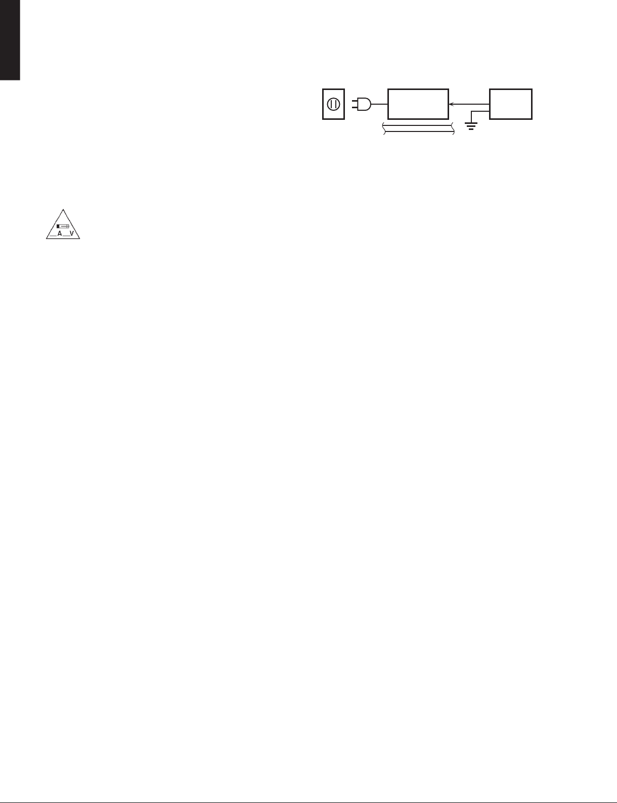
2. Leakage Current Measurement (For 120V Models Only)
When service has been completed, it is imperative to verify
that all exposed conductive surfaces are properly insulated
from supply circuits.
• Meter impedance should be equivalent to 1500 ohms shunted
by 0.15 μF.
WALL
OUTLET
• Leakage current must not exceed 0.5mA.
• Be sure to test for leakage with the AC plug in both polarities.
EQUIPMENT
UNDER TEST
INSULATING
TABLE
AC LEAKAGE
TESTER OR
EQUIVALENT
For U model
“CAUTION”
“F1501: FOR CONTINUED PROTECTION AGAINST RISK OF FIRE, REPLACE ONLY WITH SAME TYPE 6A,
125V FUSE.”
For C model
CAUTION
F1501: REPLACE WITH SAME TYPE 6A, 125V FUSE.
ATTENTION
F1501: UTILISER UN FUSIBLE DE RECHANGE DE MÉME TYPE DE 6A, 125V.
WARNING: CHEMICAL CONTENT NOTICE!
This product contains chemicals known to the State of California to cause cancer, or birth defects or other reproductive
harm.
DO NOT PLACE SOLDER, ELECTRICAL/ELECTRONIC OR PLASTIC COMPONENTS IN YOUR MOUTH FOR ANY REASON
WHATSOEVER!
Avoid prolonged, unprotected contact between solder and your skin! When soldering, do not inhale solder fumes or
expose eyes to solder/flux vapor!
If you come in contact with solder or components located inside the enclosure of this product, wash your hands before
handling food.
About lead free solder /
All of the P.C.B.s installed in this unit and solder joints are
soldered using the lead free solder.
Among some types of lead free solder currently available,
it is recommended to use one of the following types for
the repair work.
• Sn + Ag + Cu (tin + silver + copper)
• Sn + Cu (tin + copper)
• Sn + Zn + Bi (tin + zinc + bismuth)
Caution:
As the melting point temperature of the lead free solder
is about 30°C to 40°C (50°F to 70°F) higher than that of
the lead solder, be sure to use a soldering iron suitable
to each solder.
無鉛ハンダについて
本機に搭載されているすべての基板およびハンダ付けに
よる接合部は無鉛ハンダでハンダ付けされています。
無鉛ハンダにはいくつかの種類がありますが、修理時に
は下記のような無鉛ハンダの使用を推奨します。
Sn+Ag+Cu(錫+銀+銅)
Sn+Cu(錫 + 銅)
Sn+Zn+Bi(錫 + 亜鉛 + ビスマス)
注意:
無鉛ハンダの融点温度は通常の鉛入りハンダに比べ 30 〜
40℃程度高くなっていますので、それぞれのハンダに合っ
たハンダごてをご使用ください。
2
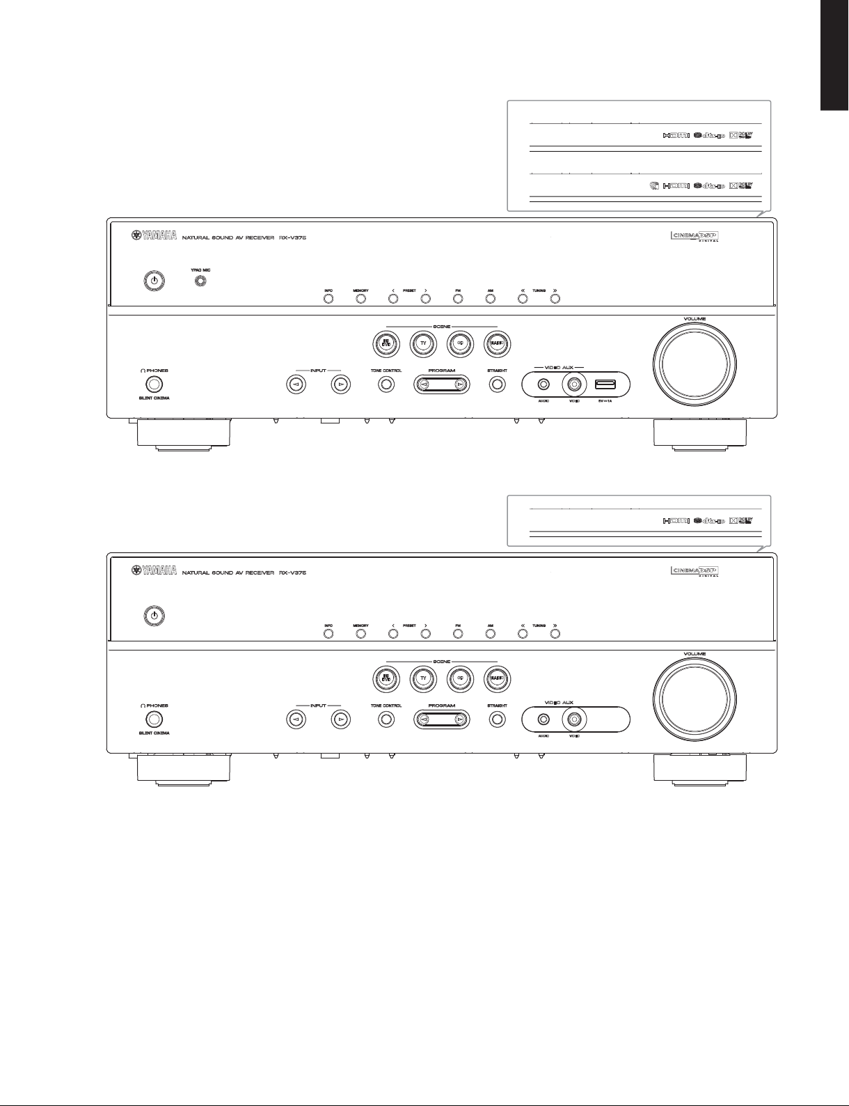
■ FRONT PANELS
RX-V375 (U, C, R, K, A, B, G, F, L, S, H, J models)
RX-V375/HTR-3066/HTR-2866
U, C, R, K, A, B, G, F, L, S, H models
J model
RX-V375/HTR-3066/
HTR-2866
RX-V375 (T model)
3
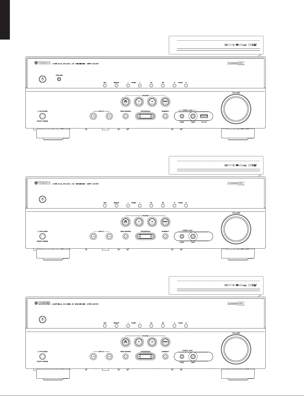
RX-V375/HTR-3066/HTR-2866
HTR-2866
RX-V375/HTR-3066/
HTR-3066 (U, C, R, K, A, B, G, F, L, S, H models)
HTR-3066 (T model)
HTR-2866 (C, R, K, A, B, G, F, L, S, H models)
4
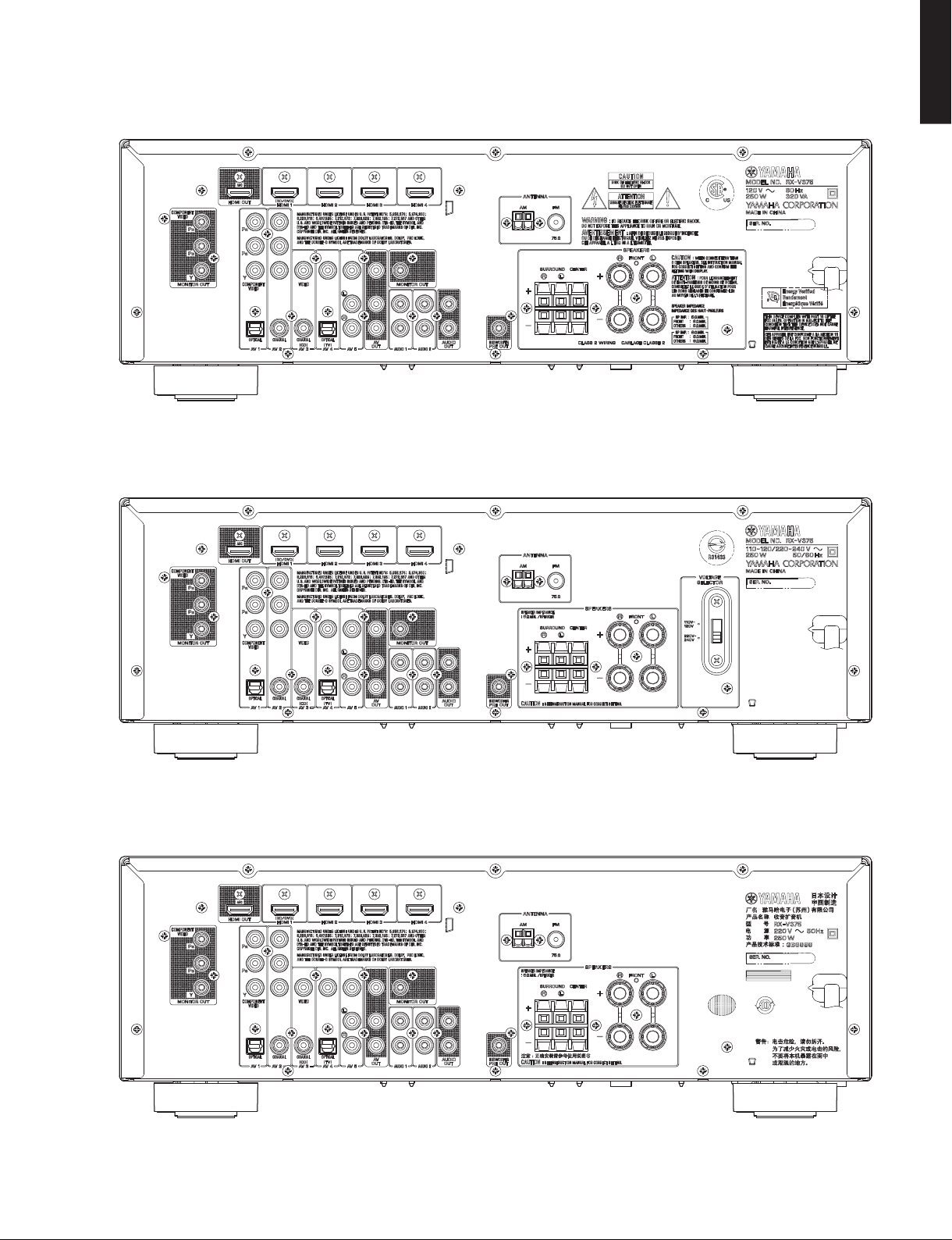
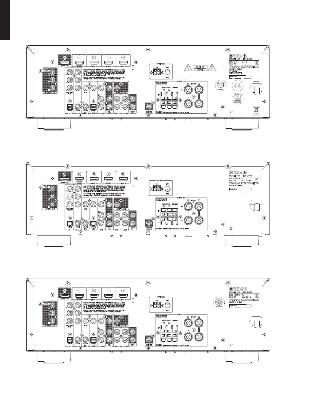
■ REAR PANELS
RX-V375 (U, C models)
RX-V375/HTR-3066/HTR-2866
RX-V375/HTR-3066/
HTR-2866
RX-V375 (R, S models)
RX-V375 (T model)
5
RX-V375/HTR-3066/HTR-2866
HTR-2866
RX-V375/HTR-3066/
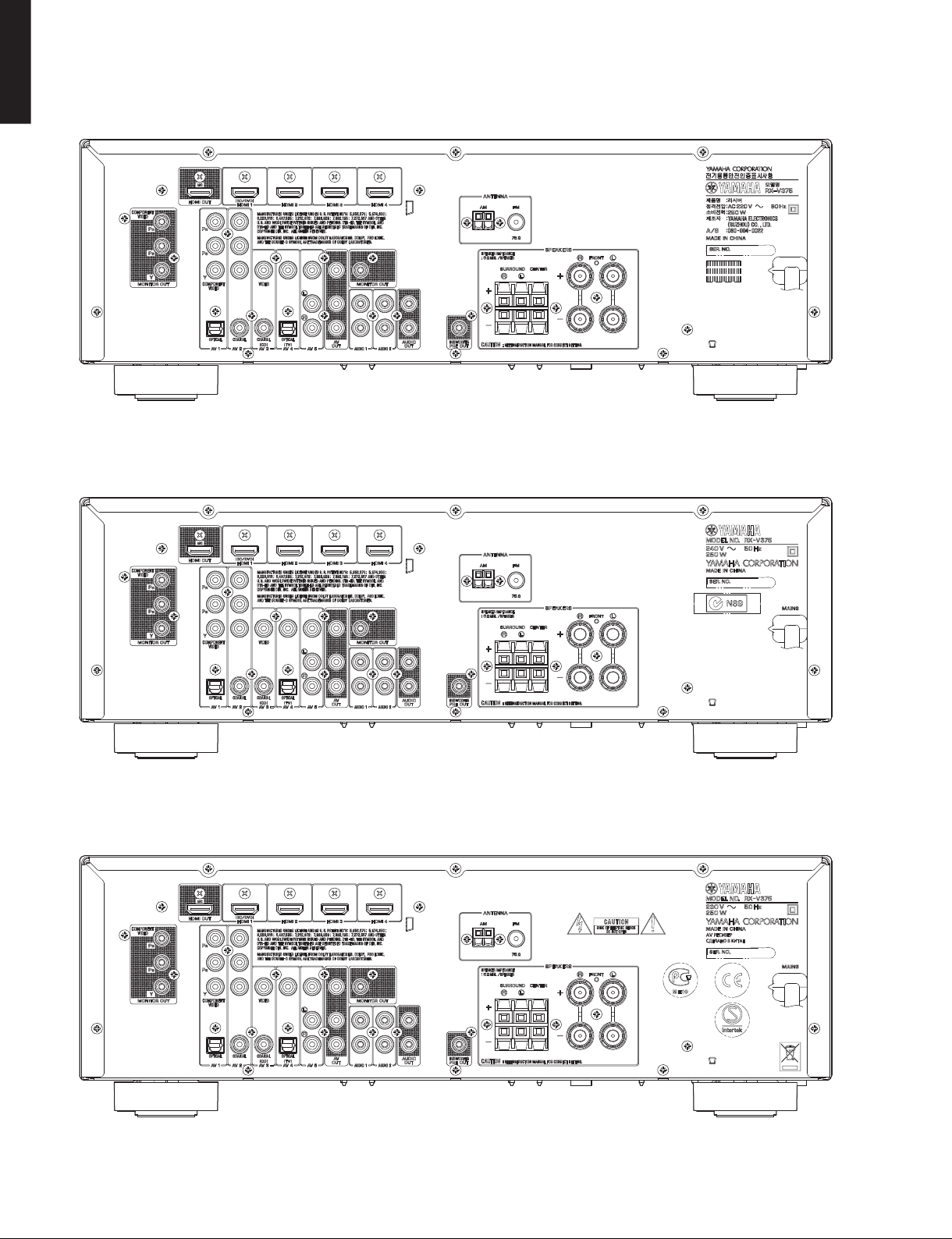
RX-V375 (K model)
RX-V375 (A model)
RX-V375 (B, G, F models)
6

RX-V375 (L model)
RX-V375/HTR-3066/HTR-2866
RX-V375/HTR-3066/
HTR-2866
RX-V375 (H model)
RX-V375 (J model)
7
RX-V375/HTR-3066/HTR-2866
HTR-2866
RX-V375/HTR-3066/
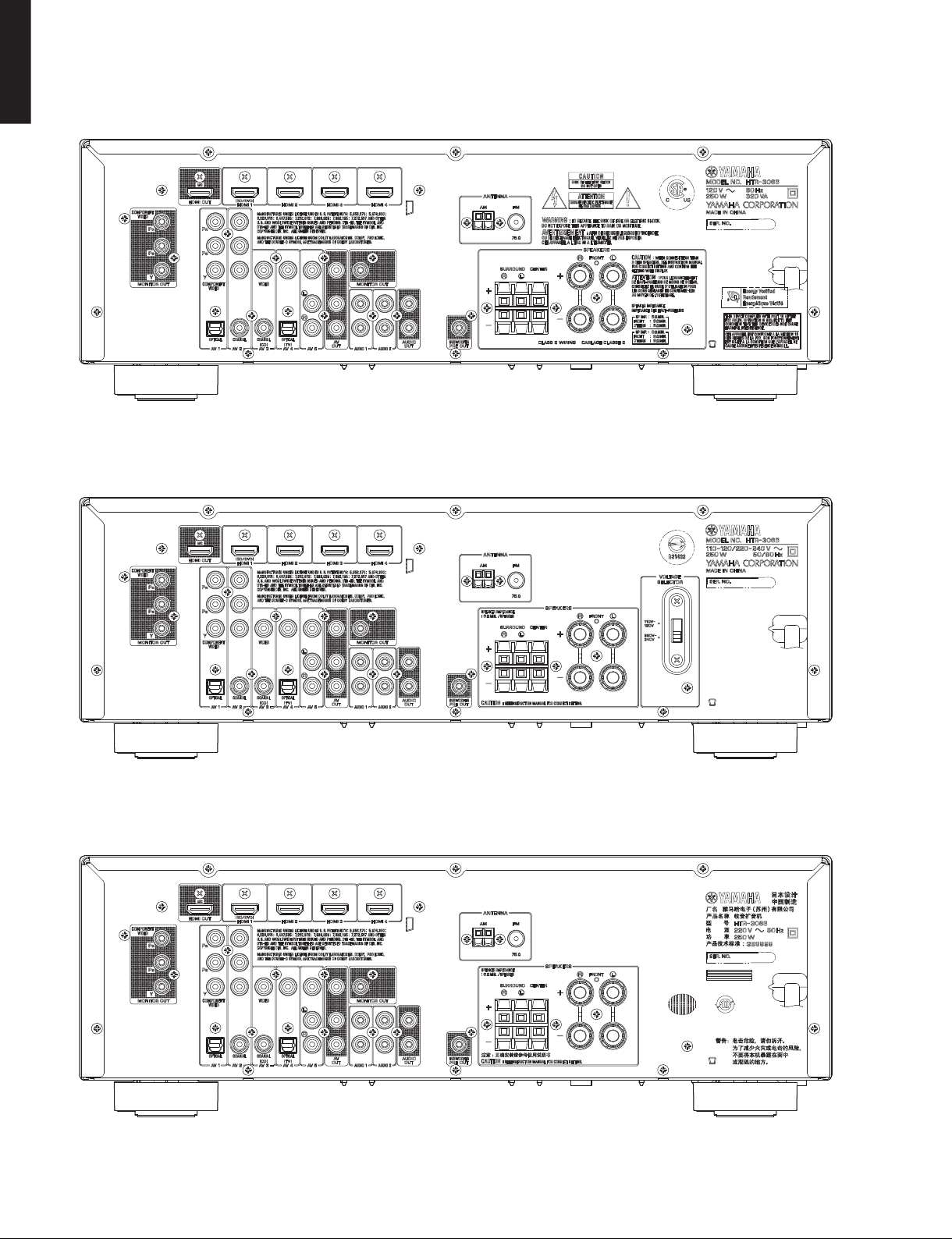
HTR-3066 (U, C models)
HTR-3066 (R, S models)
HTR-3066 (T model)
8
HTR-3066 (K model)
RX-V375/HTR-3066/HTR-2866
RX-V375/HTR-3066/
HTR-2866
HTR-3066 (A model)
HTR-3066 (B, G, F models)
9

RX-V375/HTR-3066/HTR-2866
HTR-2866
RX-V375/HTR-3066/
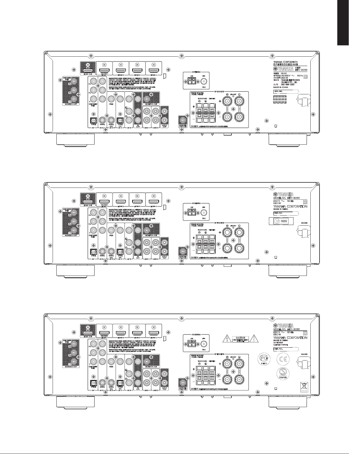
HTR-3066 (L model)
HTR-3066 (H model)
HTR-2866 (C model)
10

HTR-2866 (R, S models)
RX-V375/HTR-3066/HTR-2866
RX-V375/HTR-3066/
HTR-2866
HTR-2866 (K model)
HTR-2866 (A model)
11
RX-V375/HTR-3066/HTR-2866
HTR-2866
RX-V375/HTR-3066/
HTR-2866 (B, G, F models)
HTR-2866 (L model)
HTR-2866 (H model)
12
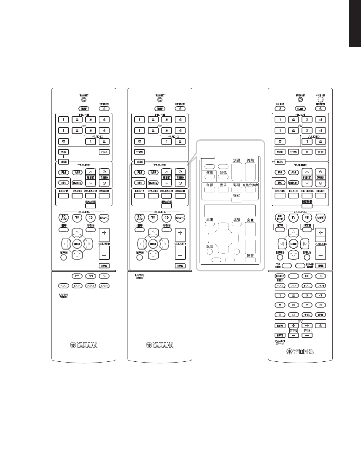
■ REMOTE CONTROL PANELS
RAV463
RX-V375
U, C, R, K, B, G, F, L, S, H, J models
(
HTR-3066
(
U, C, R, K, B, G, F, L, S, H models
)
)
(C, R, K, A, B, G, F, L, S, H models)
RAV462
RX-V375 (T model)
HTR-3066 (T model)
HTR-2866
Remote control sheet
(T model)
RX-V375/HTR-3066/HTR-2866
RAV491
RX-V375 (A model)
HTR-3066 (A model)
RX-V375/HTR-3066/
HTR-2866
13

RX-V375/HTR-3066/HTR-2866
HTR-2866
RX-V375/HTR-3066/
■ SPECIFICATIONS /
■ Audio Section /
Rated Output Power (Power Amp. Section) /
定格出力(パワーアンプ部)
(1 kHz, 0.9 % THD)
– 1 channel driven –
U, C models (8 ohms)
R, T, K, A, B, G, F, L, S, H, J models (6 ohms)
– 2 channels driven simultaneously –
U, C models (8 ohms)
(20 Hz to 20 kHz, 0.09 % THD)
– 2 channels driven simultaneously –
U, C models (8 ohms)
R, T, K, A, B, G, F, L, S, H, J models (6 ohms)
Maximum Effective Output Power /
(1 kHz, 10 % THD, 6 ohms / 1 channel driven)
[R, T, K, L, S, H, J models]
FRONT L/R ………………………………………………………………. 135 W/ch
CENTER ………………………………………………………………………. 135 W
SURROUND L/R ……………………………………………………….135 W/ch
Dynamic Power Per Channel /
FRONT L/R (1 channel driven)
U, C models
(8 / 6 / 4 / 2 ohms) ……………………………. 110 / 130 / 160 / 180 W
R, T, K, A, B, G, F, L, S, H, J models
(6 / 4 / 2 ohms) ………………………………………… 110 / 130 / 150 W
Dynamic Headroom [U, C models]
8 ohms ……………………………………………………………………….0.23 dB
Damping Factor /
FRONT L/R to SPEAKER-A ……………………………………..120 or more
Input Sensitivity/Input Impedance /
(1 kHz, 100 W/8 ohms)
AV5 etc. ……………………………………………………200 mV / 47 k-ohms
Maximum Input Signal /
AV5 etc. (EFFECT ON) …………………………………………………….. 2.3 V
Output Level/Output Impedance /
AV OUT …………………………………………………… 200 mV / 1.2 k-ohms
SUBWOOFER (2 ch stereo and FRONT SP: small)
………………………………………………………………….. 1 V / 1.2 k-ohms
Headphone Jack Rated Output/Output Impedance /
ヘッドホン出力/出力インピーダンス
AV5 etc. input ……………………………………………..100 mV / 470 ohms
Frequency Response /
AV5 etc., FRONT …………………………………………………………0 / -3 dB
参考仕様
オーディオ部
FRONT L/R ………………………………………………………. 100 W/ch
CENTER ……………………………………………………………….. 100 W
SURROUND L/R ……………………………………………….. 100 W/ch
FRONT L/R ………………………………………………………. 100 W/ch
CENTER ……………………………………………………………….. 100 W
SURROUND L/R ……………………………………………….. 100 W/ch
FRONT L/R …………………………………………………..85 W + 85 W
CENTER …………………………………………………………………. 85 W
SURROUND L/R ……………………………………………85 W + 85 W
FRONT L/R …………………………………………………..70 W + 70 W
FRONT L/R …………………………………………………..70 W + 70 W
(JEITA)
(IHF)
ダイナミックパワー
ダンピングファクタ
最大許容入力
出力電圧/出力インピーダンス
再生周波数帯域
実用最大出力
(20 Hz to 20 kHz, 8 ohms)
入力感度/入力インピーダンス
(1 kHz, 0.5 % THD)
(1 kHz, 50 mV, 8 ohms)
(10 Hz to 100 kHz)
Signal to Noise Ratio /
AV5, etc. (PURE DIRECT) to SP OUT (Input shorted 250 mV)
…………………………………………………………………… 100 dB or more
Residual Noise /
FRONT L/R to SP OUT …………………………………………150 μV or less
Channel Separation /
AV5, etc. (Input 5.1 k-ohms shorted)
1 kHz / 10 kHz …………………………. 60 dB or more / 45 dB or more
Volume Control /
………………………………….. MUTE / -80 dB to +16.5 dB / 0.5 dB step
Tone Control Characteristics /
FRONT L/R
Bass
Boost/Cut ……………………………….. ±6 dB / 0.5 dB step, at 50 Hz
Turnover frequency ………………………………………………….350 Hz
Treble
Boost/Cut ……………………………….±6 dB / 0.5 dB step, at 20 kHz
Turnover frequency …………………………………………………3.5 kHz
Filter Characteristics /
FRONT, CENTER, SURROUND small (H.P.F.)
………………..fc=40/60/80/90/100/110/120/160/200 Hz, 12 dB/oct.
SUBWOOFER small (L.P.F.)
………………..fc=40/60/80/90/100/110/120/160/200 Hz, 24 dB/oct.
Optical Jack, Coaxial Jack Support Frequencies /
Optical 端子、Coaxial 端子対応 fs
……………………………………………………………………. 32 kHz to 96 kHz
■ Video Section /
Video Signal Type /
U, C, R, K, S, J models ……………………………………………………NTSC
T, A, B, G, F, L, H models …………………………………………………… PAL
Composite Video Signal Level /
…………………………………………………………………….1 Vp-p / 75 ohms
Component Video Signal Level /
Y …………………………………………………………………..1 Vp-p / 75 ohms
Pb/Pr ………………………………………………………….0.7 Vp-p / 75 ohms
Video Maximum Input Level /
(VIDEO Conversion Off)
……………………………………………………………………. 1.5 Vp-p or more
Video Signal to Noise Ratio /
……………………………………………………………………….. 50 dB or more
Monitor Out Frequency Response /
(VIDEO Conversion Off)
Component video signal level /
…………………………………………………………..5 Hz to 60 MHz, -3 dB
信号対雑音比
残留ノイズ
チャンネルセパレーション
可変範囲/ステップ
フィルタ特性
ビデオ部
ビデオ信号方式
(IHF-A network)
(IHF-A network)
トーンコントロール特性
コンポジットビデオ信号
コンポーネントビデオ信号
ビデオ最大許容入力
ビデオ信号対雑音比
モニター出力周波数帯域
コンポーネントビデオ信号
14
RX-V375/HTR-3066/HTR-2866
RX-V375/HTR-3066/
HTR-2866
■ FM Section /
Tuning Range /
FM部
受信周波数範囲
U, C models ………………………………………………… 87.5 to 107.9 MHz
R, L, S, H models ………….87.5 to 108.0 MHz / 87.50 to 108.00 MHz
T, K, A, B, G, F models ………………………………87.50 to 108.00 MHz
J model …………………………………………………………76.0 to 90.0 MHz
50 dB Quieting Sensitivity /
50dBSN 感度
(IHF)
(1 kHz, 100 % MOD.)
Mono ………………………………………………………………. 2 μV (17.3 dBf)
Signal to Noise Ratio /
信号対雑音比
(IHF)
Mono …………………………………………………………………………….71 dB
Stereo …………………………………………………………………………..70 dB
Harmonic Distortion / 歪率 (1 kHz)
Mono ……………………………………………………………………………. 0.5 %
Stereo …………………………………………………………………………..0.6 %
Antenna Input /
アンテナ入力
…………………………………………………………….. 75 ohms unbalanced
■ AM Section /
Tuning Range /
AM部
受信周波数範囲
U, C models ………………………………………………….. 530 to 1,710 kHz
R, L, S, H models ………………… 530 to 1,710 kHz / 531 to 1,611 kHz
T, K, A, B, G, F, J models …………………………………531 to 1,611 kHz
Antenna /
アンテナ
…………………………………………………………………………. Loop antenna
■ General /
Power Supply /
総合
電源電圧
U, C models …………………………………………………… AC 120 V, 60 Hz
R, S models ……………………………AC 110–120/220–240 V, 50/60 Hz
T model …………………………………………………………. AC 220 V, 50 Hz
K model ………………………………………………………… AC 220 V, 60 Hz
A model ………………………………………………………… AC 240 V, 50 Hz
B, G, F models ……………………………………………….. AC 230 V, 50 Hz
L, H models ……………………………………….. AC 220–240 V, 50/60 Hz
J model …………………………………………………….. AC 100 V, 50/60 Hz
Power Consumption /
消費電力
U, C models …………………………………………………….. 250 W / 320 VA
R, T, K, A, B, G, F, L, S, H models ……………………………………. 250 W
J model ………………………………………………………………………..175 W
Standby Power Consumption (reference data) /
待機時消費電力(参考値)
U, C, T, K, A, B, G, F, L, H, J models ……………………….0.3 W or less
R, S models …………………………………………………………0.5 W or less
Maximum Power Consumption [R, S models]
…………………………………………………………………………………… 470 W
Dimensions (W x H x D) /
寸法(幅 × 高さ × 奥行き)
………………………………. 435 x 151 x 315 mm (17-1/8″ x 6″ x 12-3/8″)
Weight / 質量
……………………………………………………………………. 7.4 kg (16.3 lbs.)
Finish /
仕上げ
[RX-V375]
T model ………………………………………………………………..Gold color
U, C, R, T, K, A, B, G, F, L, S, H, J models ………………. Black color
R, K, B, G, F, L models ………………………………………Titanium color
[HTR-3066]
T model ………………………………………………………………..Gold color
U, C, R, T, K, A, B, G, F, L, S, H models ………………….. Black color
B, G models …………………………………………………….Titanium color
[HTR-2866]
C, R, K, A, B, G, F, L, S, H models …………………………. Black color
B, G models …………………………………………………….Titanium color
Accessories /
付属品
Remote control ……………………………………………………………………x 1
Battery (R03, AAA, UM-4) …………………………………………………….x 2
FM antenna (1.4 m) …………………………………………………………….x 1
AM antenna (1.3 m) …………………………………………………………….x 1
YPAO microphone (6 m)
(RX-V375/HTR-3066:
U, C, R, K, A, B, G, F, L, S, H, J models
) …….x 1
Remote control sheet (T model) ……………………………………………x 1
* Specifications are subject to change without notice.
※ 参考仕様および外観は、製品の改良のため予告なく変更すること
があります。
U …………………..U.S.A. model
C ……………..Canadian model
R ………………..General model
T ……………….. Chinese model
K …………………Korean model
A …………….Australian model
G ……………..European model
F ……………….. Russian model
L ……………..Singapore model
S ……………….Brazirian model
H ……………………..Thai model
J ……………… Japanese model
B ………………….British model
Manufactured under license from Dolby Laboratories. Dolby, Pro Logic and
the double-D symbol are trademarks of Dolby Laboratories.
ドルビーラボラトリーズからの実施権に基づき製造されています。Dolby、ドル
ビー、ProLogic およびダブル D 記号はドルビーラボラトリーズの商標です。
DTS-HD, the Symbol, & DTS-HD and the Symbol together are registered
trademarks of DTS, Inc. Product includes software. © DTS, Inc. All Rights
Reserved.
DTS-HD および記号は DTS 社の登録商標です。また、DTS-HD ロゴは DTS 社の
商標です。製品にはソフトウェアを含みます。著作権 DTS 社。不許複製。
iPhone, iPod, iPod classic, iPod nano and iPod touch are trademarks of
Apple Inc., registered in the U.S. and other countries.
iPhone、iPod、iPodclassic、iPodnano、iPodtouch は、米国およびその他
の国々で登録されている AppleInc. の商標です。
HDMI, the HDMI Logo, and High-Definition Multimedia Interface are
trademarks or registered trademarks of HDMI Licensing LLC in the United
States and other countries.
HDMI、HDMI ロゴ、および High-DefinitionMultimediaInterface は、米国およ
びその他の国々における HDMILicensingLLC の商標または登録商標です。
15
RX-V375/HTR-3066/HTR-2866
HTR-2866
RX-V375/HTR-3066/
“x.v.Color” is a trademark of Sony Corporation.
「x.v.Color」は、ソニー株式会社の商標です。
“SILENT CINEMA” is a trademark of Yamaha Corporation.
「サイレントシネマ™ SILENTCINEMA™」はヤマハ株式会社の登録商標です。
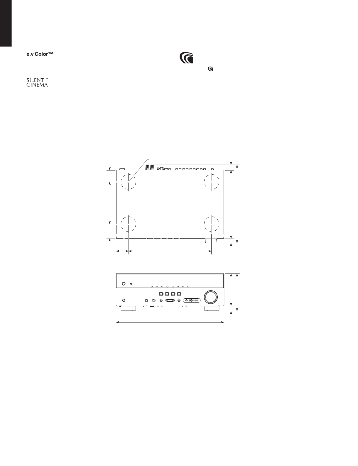
• DIMENSIONS
47
Top view
(1-7/8″)
ø 60
AAC ロゴマーク
はドルビーラボラトリーズの商標です。
27
(1″)
170 (6-5/8″)
58
50
(2″)
(2-1/4″)
Front view
335 (13-1/4″)
435 (17-1/8″)
315 (12-3/8″)
275 (10-7/8″)
22
(7/8″)
130 (5-1/8″)
151 (5-7/8″)
21
Unit: mm (inch)
(7/8″)
単位:mm(インチ)
16
• SET MENU TABLE
RX-V375/HTR-3066/HTR-2866
RX-V375/HTR-3066/
HTR-2866
MAIN
MENU
Speaker Configuration Subwoofer [Use] / None
SUB-MENU PARAMETER VALUE [INITIAL VALUE]
Front [Small] / Large
Center [Small] / Large / None
Surround [Small] / Large / None
Crossover 40 Hz / 60 Hz / [80 Hz] / 90 Hz / 100Hz / 110 Hz / 120 Hz / 160 Hz /
200 Hz
Subwoofer Phase [Normal] / Reverse
Extra Bass [Off] / On
* “Extra Bass” is not available when “Subwoofer” is set to “None”, or
when “Front” is set to “Small”.
“ExtraBass” は “Subwoofer:None” または “Front:Small” と
設定した場合、選択不可能
Distance Unit Meter / Feet
Front L 0.30 to 24.00 m, [3.00 m], 0.05 m step
Front R 1.0 to 80.0 ft, [10.0 ft], 0.2 ft step
Center 0.30 to 24.00 m, [2.60 m], 0.05 m step
1.0 to 80.0 ft, [8.6 ft], 0.2 ft step
Surround L 0.30 to 24.00 m, [2.40 m], 0.05 m step
Surround R 1.0 to 80.0 ft, [8.0 ft], 0.2 ft step
Subwoofer 0.30 to 24.00 m, [3.00 m], 0.05 m step
1.0 to 80.0 ft, [10.0 ft], 0.2 ft step
Level Front L
Front R
Center
Surround L -10.0 to +10.0 dB, [-1.0 dB], 0.5 dB step
Surround R
Subwoofer -10.0 to +10.0 dB, [0.0 dB], 0.5 dB step
Equalizer EQ Select PEQ / [GEQ] / Off (
GEQ Edit Front L 63 Hz ···········||···········
Front R 160 Hz ···········||···········
Center 400 Hz ···········||···········
Surround L 1 kHz ···········||··········· -6.0 to +6.0 dB, [0 dB], 0.5 dB step
Surround R 2.5 kHz ···········||···········
6.3 kHz ···········||···········
16 kHz ···········||···········
Test Tone [Off] / On
-10.0 to +10.0 dB, [0.0 dB], 0.5 dB step
[GEQ] / Off (
* “PEQ” is available only when the YPAO has been performed
“PEQ”
RX-V375/HTR-3066: U, C, R, K, A, B, G, F, L, S, H, J models
HTR-2866
)
は自動測定(
YPAO
)実行後のみ選択可能
)
17

RX-V375/HTR-3066/HTR-2866
HTR-2866
RX-V375/HTR-3066/
MAIN
MENU
HDMI Configuration HDMI Control [Off] / On (U, C, R, T, K, A, B, G, F, L, S, H models)
Sound DSP Parameter Panorama [Off] / On
ECO Auto Power Standby U, C, R, T, K, A, L, S, H, J models:
Function Input Rename Input sources: HDMI1 / HDMI2 / HDMI3 / HDMI4 / AV1 / AV2 / AV3 /
Language English (English) /
(U, C, R, T, K, A, B, G, F, L, S, H models) Italiano (Italian) / 中文 (Chinese)
SUB-MENU PARAMETER VALUE [INITIAL VALUE]
Off / [On] (J model)
Audio Output Amp Off / [On]
HDMI OUT (TV) [Off] / On
* This setting is available only when “HDMI Control” is set to “Off”.
“HDMI Control”が“Off”
TV Audio Input AV1 / AV2 / AV3 / [AV4] / AV5 / AUDIO1 / AUDIO2
Standby Sync Off / On / [Auto]
ARC Off / [On]
SCENE BD / DVD
TV
CD
RADIO
* This setting is available only when “HDMI Control” is set to “On”.
“HDMI Control”が“On”
Center Width 0 to 7, [3]
Dimension -3 to +3, [0]
Center Image 0.0 to 1.0, [0.3]
Lipsync Select Manual / [Auto]
Adjustment 0 to 250 ms, [0 ms], 1 ms step
Volume Dynamic Range [Maximum] / Standard / Min/Auto
Max Volume -30.0 to +15.0 dB / +16.5 dB (Maximum volume), [+16.5 dB], 5.0 dB step
Initial Volume [Off] / Mute / -80.0 to +16.5 dB, 0.5 dB step
ECO Mode [Off] / On
Dimmer -4 to 0 (higher to brighten), [0]
Memory Guard [Off] / On
の場合のみ設定可能
の場合のみ設定可能
* This setting is available only when “HDMI Control” is set to “On”.
“HDMI Control”が“On”
* This setting is available only when “HDMI Control” is set to “On”.
“HDMI Control”が“On”
* This setting is available only when “HDMI Control” is set to “On”.
“HDMI Control”が“On”
Off / [On]
[Off] / On
[Off] / 2 hours / 4 hours / 8 hours /12 hours
B, G, F models:
Off / 2 Hours / 4 Hours / [8 Hours] / 12 Hours
AV4 / AV5 / AUDIO1 / AUDIO2 / USB / V-AUX
Input is possible to 9 characters
Input possible Character type
Capital: A to Z
Small: a to z
Figure: 0 to 9
Symbols: + , — etc.
Space
Preset name select: Blu-ray / DVD / SetTopBox / Game / TV / DVR /
Deutsch (German) / Español (Spanish) / Русский (Russian) /
の場合のみ設定可能
の場合のみ設定可能
の場合のみ設定可能
CD / CD-R / Satellite / VCR / Tape / MD / PC /
iPod / HD DVD
(Japanese) / Français (French) /
日本語
18

■ INTERNAL VIEW
Top view
12 436
11
Front view
12 13
10
RX-V375/HTR-3066/
RX-V375/HTR-3066/HTR-2866
1
75
9
8
OPERATION (3) P.C.B.
2
MAIN (3) P.C.B. (R, S models)
3
MAIN (1) P.C.B.
4
AM/FM TUNER
5
DIGITAL P.C.B.
6
MAIN (2) P.C.B.
7
OPERATION (4) P.C.B.
8
MAIN (5) P.C.B.
9
OPERATION (2) P.C.B.
10
MAIN (4) P.C.B.
11
POWER TRANSFORMER
12
OPERATION (7) P.C.B.
13
OPERATION (1) P.C.B.
14
OPERATION (6) P.C.B.
15
OPERATION (5) P.C.B.
HTR-2866
1415
■ SERVICE PRECAUTIONS /
サービス時の注意事項
Safety measures
• Some internal parts in this product contain high voltages
and are dangerous.
Be sure to take safety measures during servicing, such
as wearing insulating gloves.
• Note that the capacitors indicated below are dangerous
even after the power is turned off because an electric
charge remains and a high voltage continues to exist
there.
Before starting any repair work, connect a discharging
resistor (5 k-ohms/10 W) to the terminals of each
capacitor indicated below to discharge electricity.
The time required for discharging is about 30 seconds
per each.
C46 and C47 on MAIN (1) P.C.B.
C1501 on OPERATION (3) P.C.B.
安全対策
・ この製品の内部には高電圧部分があり危険です。修理
の際は、絶縁性の手袋を使用するなどの安全対策を
行ってください。
・ 下記のコンデンサには電源を OFF にした後も電荷が残
り、高電圧が維持されており危険です。
修理作業前に放電用抵抗(5k Ω /10W)を下記の各コ
ンデンサの端子間に接続して放電してください。
放電所用時間は各々約 30 秒間です。
MAIN(1)P.C.B. の C46、C47
OPERATION(3)P.C.B. の C1501
詳しくは “PRINTEDCIRCUITBOARDS” を参照してくだ
さい。
For details, refer to “PRINTED CIRCUIT BOARDS”.
19

RX-V375/HTR-3066/HTR-2866
HTR-2866
RX-V375/HTR-3066/
■ DISASSEMBLY PROCEDURES /
(Remove parts in the order as numbered.)
Disconnect the power cable from the AC outlet.
分解手順
(番号順に部品を外してください。)
AC 電源コンセントから、電源コードを抜いてください。
1. Removal of Top Cover
a. Remove 5 screws (①) and 4 screws (②). (Fig. 1)
b. Lift the rear of the top cover to remove it. (Fig. 1)
2. Removal of Front Panel Unit
a. Remove 7 screws (③). (Fig. 1)
b. Remove CB166, CB193, CB221 and CB281 (RX-V375:
U, C, R, K, A, B, G, F, L, S, H, J models / HTR-3066: U,
C, R, K, A, B, G, F, L, S, H models). (Fig. 1)
c. Unlock and remove CB136. (Fig. 1)
d. Release hook, and then remove the front panel unit.
(Fig. 1)
Remove CB136 and CB262
Connected
接続
Cable
ケーブル
Connect CB136 and CB262
Connected
接続
Unlock the connector
1
コネ クター ロック解 除
Remove the cable
2
ケーブルを外す
1 1
Lock the connector
1
コネ クター ロック
Insert the cable
2
ケーブルを差し込む
2
②
1. トップカバーの外し方
a. ①のネジ 5 本、②のネジ 4 本を外します。(Fig.1)
b. トップカバーの後部を持ち上げ、外します。(Fig.1)
2. フロントパネルユニットの外し方
a. ③のネジ 7 本を外します。(Fig.1)
b. CB166、CB193、CB221、CB281 を外します。(Fig.1)
c. ロックを外し、CB136 を外します。(Fig.1)
d. フック 1 箇所を外し、フロントパネルユニットを外し
ます。(Fig.1)
Top cover
トップカバー
①
Cable
ケーブル
1 1
③
CB136
2
Front panel unit
フロントパネルユニット
②
CB221
CB166
CB281
CB193
③
Hook
③
(U, C, R, K, A, B, G, F, L, S, H, J models)
(U, C, R, K, A, B, G, F, L, S, H models)
RX-V375
HTR-3066
Fig. 1
20

RX-V375/HTR-3066/HTR-2866
RX-V375/HTR-3066/
HTR-2866
3. Removal of DIGITAL P.C.B.
a. Remove CB222 and CB223 (Fig. 2)
b. Unlock and remove CB262. (Fig. 2)
c. Remove screw (④). (Fig. 2)
d. Remove 2 screws (⑤) and 5 screws (⑥). (Fig. 3)
e. Remove the DIGITAL P.C.B. which is connected
directly to the OPERATION (4) P.C.B. with board-toboard connectors. (Fig. 2)
4. Removal of OPERATION (4) P.C.B.
a. Remove CB194. (Fig. 2)
b. Remove screw (⑦). (Fig. 2)
c. Remove screw (⑧). (Fig. 3)
d. Remove the OPERATION (4) P.C.B. which is
connected directly to the MAIN (1) P.C.B. with boardto-board connectors. (Fig. 2)
DIGITAL P.C.B.
OPERATION (4) P.C.B.
3. DIGITALP.C.B. の外し方
a. CB222、CB223 を外します。(Fig.2)
b. ロックを外し、CB262 を外します。(Fig.2)
c. ④のネジ 1本を外します。(Fig.2)
d. ⑤のネジ 2 本、⑥のネジ 5 本を外します。(Fig.3)
e. DIGITALP.C.B.を外します。ただし、DIGITALP.C.B. は
OPERATION(4)P.C.B. に基板対基板コネクターで直
接接続されています。(Fig.2)
4. OPERATION(4)P.C.B. の外し方
a. CB194 を外します。(Fig.2)
b. ⑦のネジ 1 本を外します。(Fig.2)
c. ⑧のネジ 1 本を外します。(Fig.3)
d. OPERATION(4)P.C.B. を外します。ただし、
OPERATION(4)P.C.B. は MAIN(1)P.C.B. に基板対基
板コネクターで直接接続されています。(Fig.2)
CB223
CB222
CB262
DIGITAL P.C.B.
CB263
CB264
Board-to-board
connectors
基板対基板コネクター
CB196
CB194
CB195
CB192
CB21
Board-to-board
connectors
基板対基板コネクター
OPERATION (4) P.C.B.
MAIN (1) P.C.B.
CB191
④
⑦
CB22
Fig. 2
⑤
⑧
⑥
⑤
Fig. 3
⑨
21

RX-V375/HTR-3066/HTR-2866
HTR-2866
RX-V375/HTR-3066/
When checking the DIGITAL P.C.B.:
• Put the rubber sheet and cloth over this unit, and
place the DIGITAL P.C.B. on them. (Fig. 4)
• Connect ST201 on DIGITAL P.C.B. to the chassis
with a ground lead. (Fig. 4)
• Reconnect all cables (connectors) that have been
disconnected. Be sure to use the P.C.B. CHECKING
JIG (Part No. WW483800) to connect between the
following connectors.
• When connecting the flexible flat cable, be careful
with polarity.
CB263 on DIGITAL P.C.B. – CB196 on OPERATION
(4) P.C.B.
CB264 on DIGITAL P.C.B. – CB195 on OPERATION
(4) P.C.B.
DIGITALP.C.B. をチェックする場合には:
・ 本機の上にゴムシートと布を敷き、その上に DIGITAL
P.C.B. を置きます。(Fig.4)
・ DIGITALP.C.B. の ST201 のアースをリード線でシャー
シに接続してください。(Fig.4)
・ 外したケーブル(コネクター)をすべて接続しま
す。ただし下記のコネクター間を接続するには
P.C.B. チェック用冶具(部品番号 :WW483800)を使
用してください。
DIGITALP.C.B.のCB263‒OPERATION(4)P.C.B.の
CB196
DIGITALP.C.B.のCB264‒OPERATION(4)P.C.B.の
CB195
・ フラットケーブルを接続する際、極性に注意してく
ださい。
Rubber sheet and cloth
ゴムシートと布
ST201
Ground lead
アース線
DIGITAL P.C.B.
CB263
Fig. 4
CB264
P.C.B. CHECKING JIG
P.C.B.チェック用冶具
OPERATION (4) P.C.B.
CB196
CB195
Chassis
シャーシ
22

RX-V375/HTR-3066/HTR-2866
RX-V375/HTR-3066/
HTR-2866
When checking the MAIN (1) P.C.B.:
a. Remove the top cover. (For details, refer to “1. Removal
of Top Cover”.)
b. Remove 3 screws (⑨). (Fig. 5)
c. Remove 5 screws (⑩) and 4 screws (⑪). (Fig. 5)
d. Place the P.C.B.s (with rear panel) upright. (Fig. 6)
e. Connect the heatsink, rear panel and MAIN (1) P.C.B.
(G3) to the chassis with a ground lead. (Fig. 6)
⑨
⑩
⑪
MAIN(1)P.C.B. をチェックする場合には:
a. トップカバーを外します。(分解手順の “1. トップカ
バーの外し方” 参照)
b. ⑨のネジ 3 本を外します。(Fig.5)
c. ⑩のネジ 5 本、⑪のネジ 4 本を外します。(Fig.5)
d. リアパネルと一緒に P.C.B. を立ち上げて置きます。
(Fig.6)
e. ヒートシンク、リアパネル、MAIN(1)P.C.B. の G3
のアースをリード線でシャーシに接続してください。
(Fig.6)
Rear panel
リアパネル
⑩⑩
Fig. 5
G3
MAIN (1) P.C.B.
Heatsink
ヒートシンク
Ground lead
アース線
Chassis
シャーシ
Ground lead
アース線
Fig. 6
23

RX-V375/HTR-3066/HTR-2866
HTR-2866
RX-V375/HTR-3066/
■ UPDATING FIRMWARE /
When the following parts are replaced, the firmware must
be updated to the latest version.
ファームウェアのアップデート
下記の部品を交換した場合、ファームウェアを最新バー
ジョンにアップデートする必要があります。
DIGITAL P.C.B.
IC225 on DIGITAL P.C.B.
There are 2 types to write the firmware.
Depending on model name and destination.
Method /
Writing method using the USB storage device U, C, R, K, A,
USB フラッシュメモリーを使用して書き込む方法
Writing method using the CD
CD を使用して書き込む方法
方法
Support model name and destination /
RX-V375/HTR-3066 HTR-2866
B, G, F, L, S, H, J models
● Confirmation of firmware version and checksum
Before and after updating the firmware, check the
firmware version and checksum by using the selfdiagnostic function menu.
Start up the self-diagnostic function and select “S4.
ROM VERSION/CHECKSUM” menu.
Using the sub-menu, have the firmware version and
checksum displayed, and note them down.
(For details, refer to “SELF-DIAGNOSTIC FUNCTION”)
* When the firmware version is different from
written one after updating, perform the updating
procedure again from the beginning.
DIGITALP.C.B.
DIGITALP.C.B. の IC225
T model
● ファームウェアのバージョンとチェックサムの
対応するモデル名と仕向け先
C, R, K, A,
B, G, F, L, S, H models
確認
ファームウェアのアップデートの前後に、ファーム
ウェアのバージョンとチェックサムをダイアグで確
認します。
ダイアグを起動し、“S4.ROM VERSION/CHECKSUM”
メニューを選択します。
サブメニューでファームウェアのバージョンと
チェックサムを表示し、それらを書きとめます。
(詳細は “ダイアグ” を参照してください。)
※ アップデート後、ファームウェアのバージョンが
書き込まれたものと異なる場合、アップデートの
操作を最初からやり直してください。
● Initializing the back-up IC
(EEPROM: IC221 on DIGITAL P.C.B.)
After updating the firmware, the back-up IC MUST
be initialized by the following procedure store the
setting information (soundfield parameters, system
memory and tuner presetting, etc.) properly.
Start up the self-diagnostic function and select “S3.
FACTORY PRESET” menu.
(For details, refer to “SELF-DIAGNOSTIC FUNCTION”)
Select “PRESET RSRV”, press the “
turn off the power once and turn on the power again.
Then the back-up IC is initialized.
” (Power) key to
● バックアップ IC の初期化
(EEPROM:DIGITALP.C.B. の IC221)
ファームウェアのアップデート後、設定情報(音
場プログラムのパラメーターやシステムメモリー、
チューナープリセット等)を正常に保存するために、
下記の方法でバックアップ IC を初期化する必要が
あります。
本機のダイアグを起動し、“S3.FACTORYPRESET” メ
ニューを選択します。
(詳細は “ダイアグ” を参照してください。)
“PRESETRSRV” を選択し、“
電源を一度きってから、もう一度電源を入れるとバッ
クアップ IC が初期化されます。
”(電源)キーを押して
24
RX-V375/HTR-3066/HTR-2866
RX-V375/HTR-3066/
HTR-2866
Writing method
using the USB storage device
RX-V375/HTR-3066
(U, C, R, K, A, B, G, F, L, S, H, J models)
● Required Tools
• USB storage device
• Firmware ………………………………….. xxxx-xxxx.bin
● Preparation
1. Download the latest firmware from the specified
download source to the folder of the PC.
2. Copy the latest firmware from the PC to the root
folder of the USB storage device.
Note: When the latest firmware is copied to a sub-
folder of the USB storage device, the update
will not proceed.
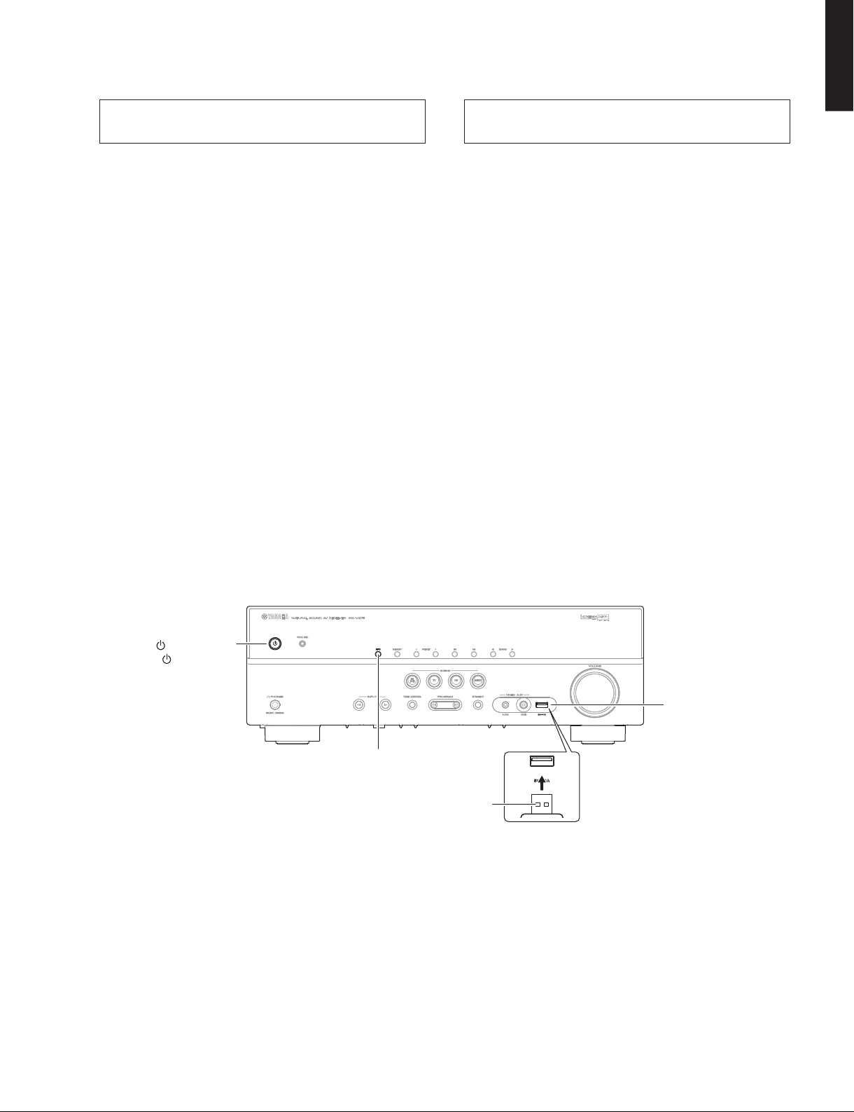
● Operation Procedures
1. Insert the USB storage device to the USB jack.
(Fig. 1)
USBフラッシュメモリーを使用して
書き込む方法
● 必要なツール
・ USB フラッシュメモリー
・ ファームウェア……………………………………… xxxx-xxxx.bin
● 準備
1. 指定のダウンロード先から、最新のファームウェ
アを PC のフォルダへダウンロードしてください。
2. PC から USB フラッシュメモリーのルートフォル
ダへ最新のファームウェアをコピーします。
注意 :最新のファームウェアをサブフォルダにコピー
した場合、書き込みはできません。
● 操作手順
1. USB 端子に USB フラッシュメモリーを差し込みま
す。(Fig.1)
2. While pressing the “INFO” key, connect the power
cable to the AC outlet. (Fig. 1)
» » (Power) key
«»(電源)キー
«INFO» key
“INFO” キー
USB storage device
USB フラッシュメモリー
2. “INFO” キーを押しながら、電源コードを AC コン
セントに接続します。(Fig.1)
USB jack
USB 端子
Fig. 1
25

RX-V375/HTR-3066/HTR-2866
HTR-2866
RX-V375/HTR-3066/
3. The USB UPDATE mode is activated and “USB
Update” is displayed. Writing of the firmware
starts automatically. (Fig. 2)
Writing is started. /
USBUpdate
書き込み開始
VERIFYING…
4. When writing of the firmware is completed,
“Update Success”, “Please…” and “Power Off!”
are displayed repeatedly. (Fig. 3)
Writing is completed. /
UpdateSuccess
書き込み完了
Please…
Fig. 2
Fig. 3
3. USBUPDATE モードが起動し、“USBUpdate” が表
示されて、ファームウェアの書き込みが自動的に
開始されます。(Fig.2)
Writing being executed. /
書き込み中
Sx-x:xx%
4. ファームウェアの書き込み完了後、“Update
Success”、“Please…”、“PowerOff!” が繰り返し表
示されます。(Fig.3)
PowerOff!
5. Press the “
” (Power) key to turn off the power.
(Fig. 1)
6. Remove the USB storage device from the USB
jack. (Fig. 1)
7. Start up the self-diagnostic function and check that
the firmware version and checksum are the same
as written ones.
(For details, refer to “Confirmation of firmware
version and checksum”)
5. “
”(電源)キーを押して電源を切ります。(Fig.1)
6. USB 端子から USB フラッシュメモリーを抜きま
す。(Fig.1)
7. ダイアグを起動し、ファームウェアのバージョン
とチェックサムが、書き込まれたものと同じであ
ることを確認します。
(詳細は “ファームウェアのバージョンとチェック
サムの確認” を参照してください。)
26
Writing method using the CD
RX-V375/HTR-3066 (T model)
HTR-2066 (C, R, K, A, B, G, F, L, S, H models)
● Required Tools
• CD, DVD or BD player (with DIGITAL OUTPUT (OPTICAL or COAXIAL) jack)
* The following models can be used as a tool to update the firmware.
CD player: CD-C600/CD-S1000/CD-S2000/CD-S300/CD-S700/CDX-496/CDX-596/CDX-890
DVD player: DV-C6760/DVD-840/DVD-C740/DVD-C750/DVD-C940/DVD-C950/DVD-CX1/DVD-S1200/
DVD-S1800/DVD-S2300(MKII)/DVD-S2700/DVD-S30/DVD-S510/DVD-S520/DVD-S530/DVD-S540/
DVD-S550/DVD-S657/DVD-S700/DVD-S80/DVD-S840
BD player: BD-940/BD-S1065/BD-S1900/BD-S2900/BD-S671
Others: CDR-D651/CDR-HD1000/CDR-HD1300/CDR-HD1500/DV-SL100/CDX-E100/CRX-430/CRX-E150/
RDX-E700
• Optical cable (when OPTICAL jack is used)
• Digital audio pin cable (when COAXIAL jack is used)
RX-V375/HTR-3066/HTR-2866
RX-V375/HTR-3066/
HTR-2866
• Firmware CD
* Download the latest firmware from the specified download source and create the firmware CD.
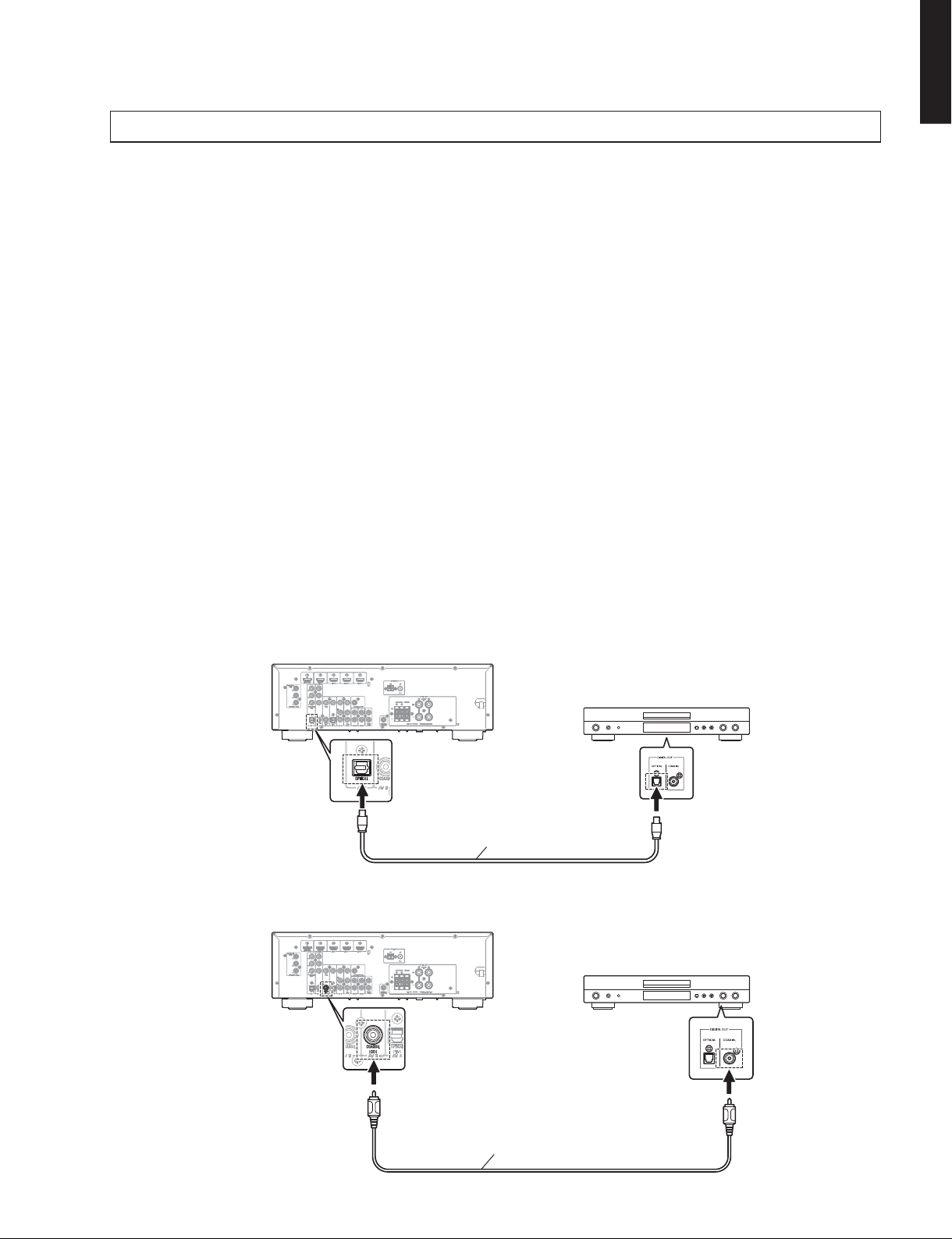
● Connection
Connect a CD/DVD/BD player to this unit as shown below. (Fig. 1)
Example of connection between digital OPTICAL jacks
This unit
Optical cable
Example of connection between digital COAXIAL jacks
This unit
CD/DVD/BD player
Digital audio pin cable
Fig. 1
CD/DVD/BD player
27

RX-V375/HTR-3066/HTR-2866
HTR-2866
RX-V375/HTR-3066/
● Operation Procedures
1. While pressing the “MEMORY” key, connect the power cable to the AC outlet. (Fig. 2)
The FIRMWARE UPDATE mode is activated and “CDDA Upgrader” is displayed. (Fig. 2)
«MEMORY» key
Display
CDDAUpgrader
Fig. 2
2. Play the firmware CD on the CD/DVD/BD player. Writing of the firmware starts automatically. (Fig. 3)
3. When writing of the firmware is completed, “Update Success”, “Please…” and “Power off!!” are displayed
repeatedly. (Fig. 3)
Writing is started Writing is completed
XXXXXXXXXX
XXXXXX
: Received data
UpdateSuccess
Please…
PowerOff!
Fig. 3
28
* If the display remains unchanged for more than 10 seconds after starting the firmware CD play procedure,
perform the firmware CD play procedure again from the beginning.
4. Press the “
” (Power) key to turn off the power.
5. Eject the firmware CD from the CD/DVD/BD player.
6. Start up the self-diagnostic function and check that the firmware version and checksum are the same as written
ones. (For details, refer to “Confirmation of firmware version and checksum”)
RX-V375/HTR-3066/HTR-2866
RX-V375/HTR-3066/
HTR-2866
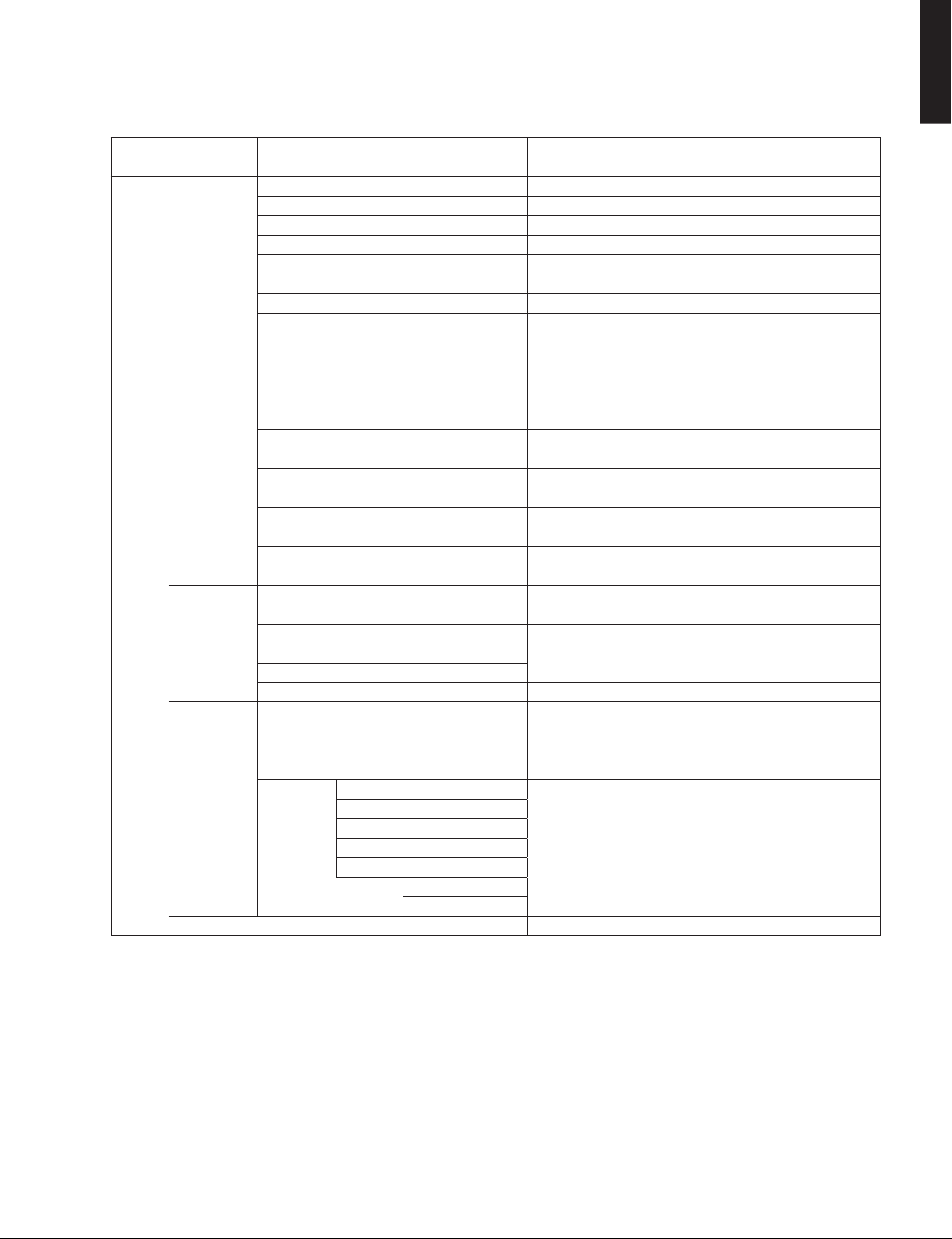
■ SELF-DIAGNOSTIC FUNCTION /
This unit has self-diagnostic functions that are intended
for inspection, measurement and location of faulty point.
There are 27 main menu items, each of which has submenu items.
Listed in the table below are main menu items and submenu items.
Note: Some of the menu items listed below may not apply
to the models covered in this service manual.
ダイアグ(自己診断機能)
本機には、検査、測定、不良個所の発見を目的にしたダ
イアグ(自己診断機能)があります。
ダイアグには 27 個のメインメニューがあり、そのそれぞ
れにサブメニューがあります。
下表はダイアグメニュー一覧です。
注意: 以下のメニュー項目の一部は、このサービスマニュ
アルに記載されているモデルに適用されない場合
があります。
No. Main menu No. Sub-menu
A: Audio system /
オーディオ系
A1 DSP AUDIO 1 DSP MARGIN
2 DSP NON MARGIN
3 DSP FULL CENTER
4 DSP FULL SURROUND
5 DSP FULL SURROUND BACK
(
6 DSP FULL SUBWOOFER
A2 DIRECT AUDIO 1 ANALOG DIRECT
2 NET DIRECT
(
A3 HDMI AUDIO 1 HDMI AUTO
2 ARC
A4 SPEAKERS SET 1 FULL MUTE
2 BI-AMP
3 AC B : HIGH
4 AC B : LOW
(
(
(
A5 MIC CHECK 1 MIC ROUTE CHECK
A6 INVALID ITEM 1 INVALID ITEM
Not for service /
(
サービスでは使用しません
)
2 INVALID ITEM
3 INVALID ITEM
A7 DIR PLL 1 DIR PLL
Not for service /
(
サービスでは使用しません
)
A8 MANUAL TEST 1 TEST ALL
H: HDMI /
HDMI
H1 INVALID ITEM 1 INVALID ITEM
Not for service /
(
D: Display system /
サービスでは使用しません
表示系
)
2 INVALID ITEM
D1 FL CHECK 1 INITIAL DISPLAY
2 ALL SEGMENT OFF
3 ALL SEGMENT ON
4 CHECK PATTERN 1
5 CHECK PATTERN 2
U: Universal system /
特殊端子系
U1 USB 1 USB FRONT 1 TRACK
2 USB BOOT
3 INVALID ITEM
(
4 APL ID CHECK
N: Network system /
ネットワーク系
N1 INVALID ITEM 1 INVALID ITEM
Not for service /
(
サービスでは使用しません
)
2 INVALID ITEM
3 INVALID ITEM
4 INVALID ITEM
5 INVALID ITEM
6 INVALID ITEM
7 INVALID ITEM
8 INVALID ITEM
9 INVALID ITEM
Not for service /
Not for service /
Not for service /
Not for service /
Not for service /
Not for service /
サービスでは使用しません
サービスでは使用しません
サービスでは使用しません
サービスでは使用しません
サービスでは使用しません
サービスでは使用しません
)
)
)
)
)
)
29

RX-V375/HTR-3066/HTR-2866
HTR-2866
RX-V375/HTR-3066/
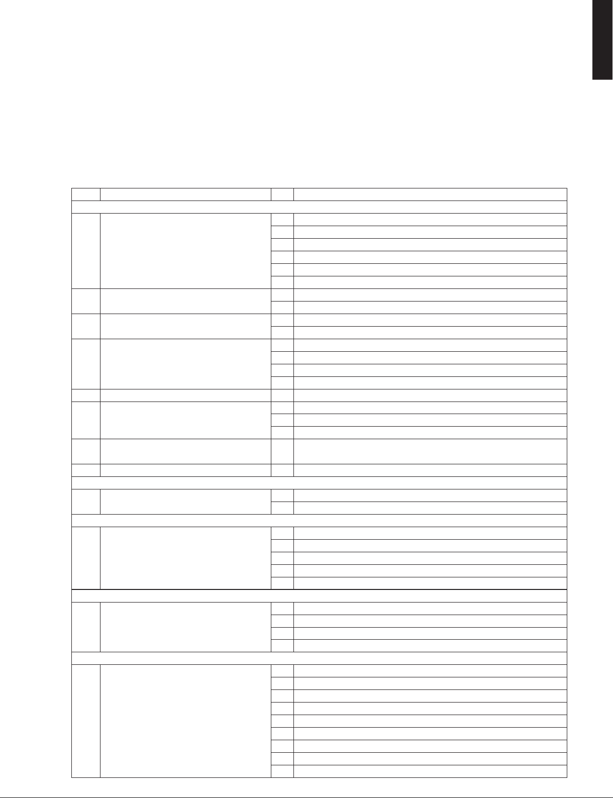
No. Main menu No. Sub-menu
C: Communication system /
C1 DIGITAL PCB CHECK 1 ALL
C2 HDMI INFO 1 HDMI MODEL NAME
C3 INVALID ITEM 1 INVALID ITEM
V: Video system /
V1 ANALOG VIDEO CHECK 1 ANALOG BYPASS
V2 DIGITAL VIDEO CHECK 1 HDMI REPEAT
R: Radio system /
R1 INVALID ITEM 1 INVALID ITEM
P: Power supply and protection system /
P1 SYSTEM MONITOR 1 DC
P2 PROTECTION HISTORY 1 HISTORY 1
T: Troubleshooting Information /
T1 TROUBLE SHOOTING INFORMATION 1 OPERATING TIME
Not for service /
(
Not for service /
(
通信・バスライン系
サービスでは使用しません
ビデオ系
TUNER・衛星放送系
サービスでは使用しません
サービス・設計用故障解析情報
2 MCPU OSD
3 OSD HDMI
4 VIDEO I/F
5 BUS DIR
6 BUS DSP
7 EEPROM
8 TUNER
2 HDMI PRODUCT ID
)
2 INVALID ITEM
3 INVALID ITEM
4 INVALID ITEM
2 MUTE CHECK
2 OSD-VIDEO OUT
)
2 INVALID ITEM
電源・プロテクション系
2PS
3 TMP
4 OUTPUT LEVEL
5 LIMITER CONTROL
6 USB-VBUS
7 KEY
2 POWER PORT 1
3 LAST INPUT 1
4 LAST VOLUME 1
5 HISTORY 2
6 POWER PORT 2
7 LAST INPUT 2
8 LAST VOLUME 2
9 HISTORY 3
10 POWER PORT 3
11 LAST INPUT 3
12 LAST VOLUME 3
13 HISTORY 4
14 POWER PORT 4
15 LAST INPUT 4
16 LAST VOLUME 4
2 POWER-RELAY ON
3 POWER AMP B
4 OUTPUT LEVEL
5 NRC (Net Restart Counter)
Not for service /
(
Not for service /
(
Not for service /
(
Not for service /
(
サービスでは使用しません
サービスでは使用しません
サービスでは使用しません
サービスでは使用しません
)
)
)
)
30
Loading…
Yamaha RX-V375
AV Receiver
Owner’s Manual
English
Read the supplied booklet “Safety Brochure” before using the unit.
View the manual for the Yamaha RX-V375 here, for free. This user manual comes under the category receivers and has been rated by 28 people with an average of a 8.2. This manual is available in the following languages: English. Do you have a question about the Yamaha RX-V375?
Ask your question here
Index
- Accessories
- FEATURES
- PREPARATIONS
- PLAYBACK
- CONFIGURATIONS
- APPENDIX
Product Images (3)

Yamaha RX-V375 specifications
Below you will find the product specifications and the manual specifications of the Yamaha RX-V375.
The Yamaha RX-V375 receiver is an audio device capable of providing 5.1 channels of high-quality sound. With a power output of 70 W per channel at 8 Ohm and a dynamic power output of 130 W per channel at 4 Ohm, the Yamaha RX-V375 is powerful enough for most home setups. The device features four HDMI inputs, two component video inputs, four composite video inputs, four audio (L/R) inputs, two digital audio optical inputs, and two digital audio coaxial inputs. In addition to these inputs, the Yamaha RX-V375 also has one USB port and one HDMI output. It also comes with one component video output, one composite video output, and two audio (L/R) outputs. This receiver has a headphone output for private listening.
Designed with premium materials, the Yamaha RX-V375 ensures durability over time. It is user-friendly and easy to set up and operate. The receiver is compatible with numerous devices and supports a range of audio formats, making it versatile and suitable for different needs. The Yamaha RX-V375 has a sleek and modern design that adds an elegant touch to any home theater setup.
Power output per channel (20-20KHz@8 Ohm)
70 W
Speakers connectivity type
—
Supported radio bands
AM, FM
General
| Brand | Yamaha |
| Model | RX-V375 | RX-V375BL |
| Product | receiver |
| EAN | 4957812528832 |
| Language | English |
| Filetype | User manual (PDF), Installation Guide (PDF) |
Audio
| Power output per channel (20-20KHz@8 Ohm) | 70 W |
| Audio output channels | 5.1 channels |
| Dynamic power per channel (4 Ohm) | 130 W |
| Receiver type | Surround |
Inputs
| HDMI in | 4 |
| Component video (YPbPr/YCbCr) in | 2 |
| Composite video in | 4 |
| Audio (L/R) in | 4 |
| Digital audio optical in | 2 |
| Digital audio coaxial in | 2 |
| USB ports quantity | 1 |
Outputs
| Number of HDMI outputs | 1 |
| Component video (YPbPr/YCbCr) out | 1 |
| Composite video out | 1 |
| Audio (L/R) out | 2 |
| Headphone outputs | 1 |
Ports & interfaces
| Speakers connectivity type | — |
Network
Radio
| Supported radio bands | AM, FM |
Optical drive
| Optical drive included | No |
Storage
| Card reader integrated | No |
Technical details
| Display | LCD |
| Audio decoders | Dolby Digital Plus, Dolby TrueHD, DTS-HD Master Audio |
| Remote control included | Yes |
| Product colour | Black |
| Apple docking compatibility | Not supported |
| AirPlay | No |
Weight & dimensions
| Width | 435 mm |
| Depth | 315 mm |
| Height | 151 mm |
| Weight | 7400 g |
Video
Packaging content
| Manual | Yes |
| Warranty card | Yes |
| User guide | Yes |
show more
Frequently asked questions
Can’t find the answer to your question in the manual? You may find the answer to your question in the FAQs about the Yamaha RX-V375 below.
What is the weight of the Yamaha RX-V375?
The Yamaha RX-V375 has a weight of 7400 g.
Can bluetooth devices of different brands be connected to each other?
Yes, bluetooth is a universal method that allows different devices equipped with bluetooth to connect to each other.
What is the height of the Yamaha RX-V375?
The Yamaha RX-V375 has a height of 151 mm.
What is the width of the Yamaha RX-V375?
The Yamaha RX-V375 has a width of 435 mm.
What is bluetooth?
Bluetooth is a way of exchanging data wirelessly between electronic devices via radio waves. The distance between the two devices that exchange data can in most cases be no more than ten metres.
What is the depth of the Yamaha RX-V375?
The Yamaha RX-V375 has a depth of 315 mm.
What is HDMI?
HDMI stands for High-Definition Multimedia Interface. An HDMI cable is used to transport audio and video signals between devices.
When is my volume too loud?
A volume above 80 decibels can be harmful to hearing. When the volume exceeds 120 decibels, direct damage can even occur. The chance of hearing damage depends on the listening frequency and duration.
How can I best clean my receiver?
A slightly damp cleaning cloth or soft, dust-free cloth works best to remove fingerprints. Dust in hard-to-reach places is best removed with compressed air.
Wat is Dolby Atmos?
Dolby Atmos is a technology that ensures that the sound is reflected from the ceiling to where you are listening. This makes it possible to create a 5.1 effect with only 1 speaker.
Is the manual of the Yamaha RX-V375 available in English?
Yes, the manual of the Yamaha RX-V375 is available in English .
Is your question not listed? Ask your question here
Перейти к контенту
Ресиверы и усилители Yamaha
- Размер инструкции: 3.30 Мб
- Формат файла: pdf
Если вы потеряли инструкцию от ресивера и усилителя Yamaha RX-V375, можете скачать файл для просмотра на компьютере или печати.
Инструкция для ресивера и усилителя Yamaha RX-V375 на русском языке. В руководстве описаны возможности и полезные функции, а также правила эксплуатации. Перед использованием внимательно ознакомьтесь с инструкцией.
Чтобы не читать всю инструкцию вы можете выполнить поиск по содержимому внутри инструкции и быстро найти необходимую информацию. Рекомендации по использованию помогут увеличить срок службы ресивера и усилителя Yamaha RX-V375. Если у вас появилась проблема, то найдите раздел с описанием неисправностей и способами их решения. В нем указаны типичные поломки и способы их решения.