

- Главная
- Продукты
- Аудио, домашний кинотеатр
- AV-Ресиверы
- RX-V579
- Загрузки
- Описание
- Функциональные особенности
- Приложения
- Потоковые сервисы
- Спецификации
- Поддержка
Прошивки / ПО
Операционная система
| Название | Операционная система | Размер | Последнее обновление |
|---|---|---|---|
| RX-V479/RX-V579/RX-A550/HTR-4068/TSR-5790 Firmware Update Ver.2.86 | — | 28.9MB | 2021-10-04 |
Руководства
| Название | Русский | English |
|---|---|---|
| Additional Features |
[443KB] |
[443KB] |
| MusicCast Setup Guide | — |
[851KB] |
| MusicCast Setup Guide |
[851KB] |
[851KB] |
| RX-V579/RX-V479 Owner’s Manual |
[15.5MB] |
[18.3MB] |
| RX-V579/RX-V479 Owner’s Manual | — |
[18.3MB] |
| Specification change related to Internet radio | — |
[242KB] |
| Specification change related to Internet radio |
[242KB] |
— |

Новости и события

Загрузки

Дополнительно
- Главная
- Продукты
- Аудио, домашний кинотеатр
- AV-Ресиверы
- RX-V579
- Загрузки

AV Receiver
Owner’s Manual
English
Read the supplied booklet “Safety Brochure” before using the unit.

CONTENTS
Accessories . . . . . . . . . . . . . . . . . . . . . . . . . . . . . . . . . . . . . . . . . . . . . . . . . . . . . . 4
FEATURES 5
What you can do with the unit . . . . . . . . . . . . . . . . . . . . . . . . . . . . . . . . . . . . 5
Part names and functions . . . . . . . . . . . . . . . . . . . . . . . . . . . . . . . . . . . . . . . . 7
Front panel . . . . . . . . . . . . . . . . . . . . . . . . . . . . . . . . . . . . . . . . . . . . . . . . . . . . . . . . . . . . . . . . . . . . . . . . . . . . . . . . . . . . . . . . 7
Front display (indicators) . . . . . . . . . . . . . . . . . . . . . . . . . . . . . . . . . . . . . . . . . . . . . . . . . . . . . . . . . . . . . . . . . . . . . . . . . . . 8
Rear panel . . . . . . . . . . . . . . . . . . . . . . . . . . . . . . . . . . . . . . . . . . . . . . . . . . . . . . . . . . . . . . . . . . . . . . . . . . . . . . . . . . . . . . . . . 9
Remote control . . . . . . . . . . . . . . . . . . . . . . . . . . . . . . . . . . . . . . . . . . . . . . . . . . . . . . . . . . . . . . . . . . . . . . . . . . . . . . . . . . . 10
PREPARATIONS 11
General setup procedure . . . . . . . . . . . . . . . . . . . . . . . . . . . . . . . . . . . . . . . . 11
1 Placing speakers . . . . . . . . . . . . . . . . . . . . . . . . . . . . . . . . . . . . . . . . . . . . . . 12
2 Connecting speakers . . . . . . . . . . . . . . . . . . . . . . . . . . . . . . . . . . . . . . . . . . 16
5.1-channel system . . . . . . . . . . . . . . . . . . . . . . . . . . . . . . . . . . . . . . . . . . . . . . . . . . . . . . . . . . . . . . . . . . . . . . . . . . . . . . . 16
7.1-channel system . . . . . . . . . . . . . . . . . . . . . . . . . . . . . . . . . . . . . . . . . . . . . . . . . . . . . . . . . . . . . . . . . . . . . . . . . . . . . . . 16
Connecting front speakers that support bi-amp connections . . . . . . . . . . . . . . . . . . . . . . . . . . . . . . . . . . . . . . . 17
Connecting Zone B speakers . . . . . . . . . . . . . . . . . . . . . . . . . . . . . . . . . . . . . . . . . . . . . . . . . . . . . . . . . . . . . . . . . . . . . . 17
Input/output jacks and cables . . . . . . . . . . . . . . . . . . . . . . . . . . . . . . . . . . . 18
3 Connecting a TV . . . . . . . . . . . . . . . . . . . . . . . . . . . . . . . . . . . . . . . . . . . . . . . 19
4 Connecting playback devices . . . . . . . . . . . . . . . . . . . . . . . . . . . . . . . . . . 21
Connecting video devices (such as BD/DVD players) . . . . . . . . . . . . . . . . . . . . . . . . . . . . . . . . . . . . . . . . . . . . . . . 21
Connecting audio devices (such as CD players) . . . . . . . . . . . . . . . . . . . . . . . . . . . . . . . . . . . . . . . . . . . . . . . . . . . . . 23
Connecting to the jack on the front panel . . . . . . . . . . . . . . . . . . . . . . . . . . . . . . . . . . . . . . . . . . . . . . . . . . . . . . . . . . 24
5 Connecting the FM/AM antennas . . . . . . . . . . . . . . . . . . . . . . . . . . . . . . . 24
6 Preparing for connecting to a network . . . . . . . . . . . . . . . . . . . . . . . . . . 25
7 Connecting the power cable . . . . . . . . . . . . . . . . . . . . . . . . . . . . . . . . . . . 26
8 Selecting an on-screen menu language . . . . . . . . . . . . . . . . . . . . . . . . . 27
9 Optimizing the speaker settings automatically (YPAO) . . . . . . . . . . 28
Error messages . . . . . . . . . . . . . . . . . . . . . . . . . . . . . . . . . . . . . . . . . . . . . . . . . . . . . . . . . . . . . . . . . . . . . . . . . . . . . . . . . . . . 30
Warning messages . . . . . . . . . . . . . . . . . . . . . . . . . . . . . . . . . . . . . . . . . . . . . . . . . . . . . . . . . . . . . . . . . . . . . . . . . . . . . . . .31
10 Connecting to a network wirelessly . . . . . . . . . . . . . . . . . . . . . . . . . . . 32
Selecting the connection method . . . . . . . . . . . . . . . . . . . . . . . . . . . . . . . . . . . . . . . . . . . . . . . . . . . . . . . . . . . . . . . . . . 32
Connecting the unit to a wireless network . . . . . . . . . . . . . . . . . . . . . . . . . . . . . . . . . . . . . . . . . . . . . . . . . . . . . . . . .33
Connecting a mobile device to the unit directly (Wireless Direct) . . . . . . . . . . . . . . . . . . . . . . . . . . . . . . . . . . . .40
PLAYBACK 42
Basic playback procedure . . . . . . . . . . . . . . . . . . . . . . . . . . . . . . . . . . . . . . . 42
Selecting the input source and favorite settings with one touch
(SCENE) . . . . . . . . . . . . . . . . . . . . . . . . . . . . . . . . . . . . . . . . . . . . . . . . . . . . . . . . 43
Selecting a registered scene . . . . . . . . . . . . . . . . . . . . . . . . . . . . . . . . . . . . . . . . . . . . . . . . . . . . . . . . . . . . . . . . . . . . . . . 43
Configuring scene assignments . . . . . . . . . . . . . . . . . . . . . . . . . . . . . . . . . . . . . . . . . . . . . . . . . . . . . . . . . . . . . . . . . . . .43
Selecting the sound mode . . . . . . . . . . . . . . . . . . . . . . . . . . . . . . . . . . . . . . . 44
Enjoying stereoscopic sound fields (CINEMA DSP 3D) . . . . . . . . . . . . . . . . . . . . . . . . . . . . . . . . . . . . . . . . . . . . . . .45
Enjoying unprocessed playback . . . . . . . . . . . . . . . . . . . . . . . . . . . . . . . . . . . . . . . . . . . . . . . . . . . . . . . . . . . . . . . . . . . 47
Enjoying pure high fidelity sound (direct playback) . . . . . . . . . . . . . . . . . . . . . . . . . . . . . . . . . . . . . . . . . . . . . . . . .48
Enhancing the bass (Extra Bass) . . . . . . . . . . . . . . . . . . . . . . . . . . . . . . . . . . . . . . . . . . . . . . . . . . . . . . . . . . . . . . . . . . . .48
Enjoying compressed music with enhanced sound (Compressed Music Enhancer) . . . . . . . . . . . . . . . . . . . 48
Listening to FM/AM radio . . . . . . . . . . . . . . . . . . . . . . . . . . . . . . . . . . . . . . . 49
Setting the frequency steps . . . . . . . . . . . . . . . . . . . . . . . . . . . . . . . . . . . . . . . . . . . . . . . . . . . . . . . . . . . . . . . . . . . . . . . .49
Selecting a frequency for reception . . . . . . . . . . . . . . . . . . . . . . . . . . . . . . . . . . . . . . . . . . . . . . . . . . . . . . . . . . . . . . . .49
Registering favorite radio stations (presets) . . . . . . . . . . . . . . . . . . . . . . . . . . . . . . . . . . . . . . . . . . . . . . . . . . . . . . . . 50
Radio Data System tuning . . . . . . . . . . . . . . . . . . . . . . . . . . . . . . . . . . . . . . . . . . . . . . . . . . . . . . . . . . . . . . . . . . . . . . . . .52
Playing back music via BLUETOOTH . . . . . . . . . . . . . . . . . . . . . . . . . . . . . . 53
Playback BLUETOOTH device music on the unit . . . . . . . . . . . . . . . . . . . . . . . . . . . . . . . . . . . . . . . . . . . . . . . . . . . .53
Playing back iPod music . . . . . . . . . . . . . . . . . . . . . . . . . . . . . . . . . . . . . . . . . 54
Connecting an iPod . . . . . . . . . . . . . . . . . . . . . . . . . . . . . . . . . . . . . . . . . . . . . . . . . . . . . . . . . . . . . . . . . . . . . . . . . . . . . . .54
Playback of iPod content . . . . . . . . . . . . . . . . . . . . . . . . . . . . . . . . . . . . . . . . . . . . . . . . . . . . . . . . . . . . . . . . . . . . . . . . . . 54
En 2

Playing back music with AirPlay . . . . . . . . . . . . . . . . . . . . . . . . . . . . . . . . . 57
Playback of iTunes/iPod music contents . . . . . . . . . . . . . . . . . . . . . . . . . . . . . . . . . . . . . . . . . . . . . . . . . . . . . . . . . . . 57
Playing back music stored on a USB storage device . . . . . . . . . . . . . . . 59
Connecting a USB storage device . . . . . . . . . . . . . . . . . . . . . . . . . . . . . . . . . . . . . . . . . . . . . . . . . . . . . . . . . . . . . . . . . . 59
Playback of USB storage device contents . . . . . . . . . . . . . . . . . . . . . . . . . . . . . . . . . . . . . . . . . . . . . . . . . . . . . . . . . . 59
Playing back music stored on media servers (PCs/NAS) . . . . . . . . . . . . 62
Media sharing setup . . . . . . . . . . . . . . . . . . . . . . . . . . . . . . . . . . . . . . . . . . . . . . . . . . . . . . . . . . . . . . . . . . . . . . . . . . . . . . 62
Playback of PC music contents . . . . . . . . . . . . . . . . . . . . . . . . . . . . . . . . . . . . . . . . . . . . . . . . . . . . . . . . . . . . . . . . . . . . 63
Listening to Internet radio . . . . . . . . . . . . . . . . . . . . . . . . . . . . . . . . . . . . . . . 65
Playback of Internet radio . . . . . . . . . . . . . . . . . . . . . . . . . . . . . . . . . . . . . . . . . . . . . . . . . . . . . . . . . . . . . . . . . . . . . . . . . 65
Registering favorite Internet radio stations (bookmarks) . . . . . . . . . . . . . . . . . . . . . . . . . . . . . . . . . . . . . . . . . . . . 67
Playing back music in multiple rooms (RX-V579 only) . . . . . . . . . . . . . 68
Connecting Zone B speakers . . . . . . . . . . . . . . . . . . . . . . . . . . . . . . . . . . . . . . . . . . . . . . . . . . . . . . . . . . . . . . . . . . . . . . 68
Operating the Zone B . . . . . . . . . . . . . . . . . . . . . . . . . . . . . . . . . . . . . . . . . . . . . . . . . . . . . . . . . . . . . . . . . . . . . . . . . . . . . 69
Useful functions . . . . . . . . . . . . . . . . . . . . . . . . . . . . . . . . . . . . . . . . . . . . . . . . 70
Registering favorite items (shortcut) . . . . . . . . . . . . . . . . . . . . . . . . . . . . . . . . . . . . . . . . . . . . . . . . . . . . . . . . . . . . . . . 70
Switching information on the front display . . . . . . . . . . . . . . . . . . . . . . . . . . . . . . . . . . . . . . . . . . . . . . . . . . . . . . . . 71
Configuring playback settings for different playback sources
(Option menu) . . . . . . . . . . . . . . . . . . . . . . . . . . . . . . . . . . . . . . . . . . . . . . . . . . 72
Option menu items . . . . . . . . . . . . . . . . . . . . . . . . . . . . . . . . . . . . . . . . . . . . . . . . . . . . . . . . . . . . . . . . . . . . . . . . . . . . . . . 72
CONFIGURATIONS 76
Configuring various functions (Setup menu) . . . . . . . . . . . . . . . . . . . . . . 76
Setup menu items . . . . . . . . . . . . . . . . . . . . . . . . . . . . . . . . . . . . . . . . . . . . . . . . . . . . . . . . . . . . . . . . . . . . . . . . . . . . . . . . 77
Speaker . . . . . . . . . . . . . . . . . . . . . . . . . . . . . . . . . . . . . . . . . . . . . . . . . . . . . . . . . . . . . . . . . . . . . . . . . . . . . . . . . . . . . . . . . . . 80
HDMI . . . . . . . . . . . . . . . . . . . . . . . . . . . . . . . . . . . . . . . . . . . . . . . . . . . . . . . . . . . . . . . . . . . . . . . . . . . . . . . . . . . . . . . . . . . . . 84
Sound . . . . . . . . . . . . . . . . . . . . . . . . . . . . . . . . . . . . . . . . . . . . . . . . . . . . . . . . . . . . . . . . . . . . . . . . . . . . . . . . . . . . . . . . . . . . 86
ECO . . . . . . . . . . . . . . . . . . . . . . . . . . . . . . . . . . . . . . . . . . . . . . . . . . . . . . . . . . . . . . . . . . . . . . . . . . . . . . . . . . . . . . . . . . . . . . 89
Function . . . . . . . . . . . . . . . . . . . . . . . . . . . . . . . . . . . . . . . . . . . . . . . . . . . . . . . . . . . . . . . . . . . . . . . . . . . . . . . . . . . . . . . . . . 90
Network . . . . . . . . . . . . . . . . . . . . . . . . . . . . . . . . . . . . . . . . . . . . . . . . . . . . . . . . . . . . . . . . . . . . . . . . . . . . . . . . . . . . . . . . . . 92
Bluetooth . . . . . . . . . . . . . . . . . . . . . . . . . . . . . . . . . . . . . . . . . . . . . . . . . . . . . . . . . . . . . . . . . . . . . . . . . . . . . . . . . . . . . . . . . 94
Language . . . . . . . . . . . . . . . . . . . . . . . . . . . . . . . . . . . . . . . . . . . . . . . . . . . . . . . . . . . . . . . . . . . . . . . . . . . . . . . . . . . . . . . . . 95
Configuring the system settings (ADVANCED SETUP menu) . . . . . . . . 96
ADVANCED SETUP menu items . . . . . . . . . . . . . . . . . . . . . . . . . . . . . . . . . . . . . . . . . . . . . . . . . . . . . . . . . . . . . . . . . . . . 96
Changing the speaker impedance setting (SP IMP.) . . . . . . . . . . . . . . . . . . . . . . . . . . . . . . . . . . . . . . . . . . . . . . . . .96
Selecting the remote control ID (REMOTE ID) . . . . . . . . . . . . . . . . . . . . . . . . . . . . . . . . . . . . . . . . . . . . . . . . . . . . . . .97
Changing the FM/AM tuning frequency setting (TU) . . . . . . . . . . . . . . . . . . . . . . . . . . . . . . . . . . . . . . . . . . . . . . . .97
Switching the video signal type (TV FORMAT) . . . . . . . . . . . . . . . . . . . . . . . . . . . . . . . . . . . . . . . . . . . . . . . . . . . . . .97
Restoring the default settings (INIT) . . . . . . . . . . . . . . . . . . . . . . . . . . . . . . . . . . . . . . . . . . . . . . . . . . . . . . . . . . . . . . . .97
Updating the firmware (UPDATE) . . . . . . . . . . . . . . . . . . . . . . . . . . . . . . . . . . . . . . . . . . . . . . . . . . . . . . . . . . . . . . . . . . 98
Checking the firmware version (VERSION) . . . . . . . . . . . . . . . . . . . . . . . . . . . . . . . . . . . . . . . . . . . . . . . . . . . . . . . . . .98
Updating the unit’s firmware via the network . . . . . . . . . . . . . . . . . . . . 99
APPENDIX 100
Frequently asked questions . . . . . . . . . . . . . . . . . . . . . . . . . . . . . . . . . . . . 100
Troubleshooting . . . . . . . . . . . . . . . . . . . . . . . . . . . . . . . . . . . . . . . . . . . . . . . 102
Power, system and remote control . . . . . . . . . . . . . . . . . . . . . . . . . . . . . . . . . . . . . . . . . . . . . . . . . . . . . . . . . . . . . . . .102
Audio . . . . . . . . . . . . . . . . . . . . . . . . . . . . . . . . . . . . . . . . . . . . . . . . . . . . . . . . . . . . . . . . . . . . . . . . . . . . . . . . . . . . . . . . . . . .104
Video . . . . . . . . . . . . . . . . . . . . . . . . . . . . . . . . . . . . . . . . . . . . . . . . . . . . . . . . . . . . . . . . . . . . . . . . . . . . . . . . . . . . . . . . . . . .105
FM/AM radio . . . . . . . . . . . . . . . . . . . . . . . . . . . . . . . . . . . . . . . . . . . . . . . . . . . . . . . . . . . . . . . . . . . . . . . . . . . . . . . . . . . . .106
USB and network . . . . . . . . . . . . . . . . . . . . . . . . . . . . . . . . . . . . . . . . . . . . . . . . . . . . . . . . . . . . . . . . . . . . . . . . . . . . . . . . .107
BLUETOOTH . . . . . . . . . . . . . . . . . . . . . . . . . . . . . . . . . . . . . . . . . . . . . . . . . . . . . . . . . . . . . . . . . . . . . . . . . . . . . . . . . . . . .108
Error indications on the front display . . . . . . . . . . . . . . . . . . . . . . . . . . . 109
Glossary . . . . . . . . . . . . . . . . . . . . . . . . . . . . . . . . . . . . . . . . . . . . . . . . . . . . . . 110
Audio information . . . . . . . . . . . . . . . . . . . . . . . . . . . . . . . . . . . . . . . . . . . . . . . . . . . . . . . . . . . . . . . . . . . . . . . . . . . . . . . .110
HDMI and video information . . . . . . . . . . . . . . . . . . . . . . . . . . . . . . . . . . . . . . . . . . . . . . . . . . . . . . . . . . . . . . . . . . . . . .111
Network information . . . . . . . . . . . . . . . . . . . . . . . . . . . . . . . . . . . . . . . . . . . . . . . . . . . . . . . . . . . . . . . . . . . . . . . . . . . . .111
Yamaha technologies . . . . . . . . . . . . . . . . . . . . . . . . . . . . . . . . . . . . . . . . . . . . . . . . . . . . . . . . . . . . . . . . . . . . . . . . . . . .112
Supported devices and file formats . . . . . . . . . . . . . . . . . . . . . . . . . . . . . 112
Video signal flow . . . . . . . . . . . . . . . . . . . . . . . . . . . . . . . . . . . . . . . . . . . . . . 113
Information on HDMI . . . . . . . . . . . . . . . . . . . . . . . . . . . . . . . . . . . . . . . . . . 114
HDMI Control . . . . . . . . . . . . . . . . . . . . . . . . . . . . . . . . . . . . . . . . . . . . . . . . . . . . . . . . . . . . . . . . . . . . . . . . . . . . . . . . . . . .114
Audio Return Channel (ARC) . . . . . . . . . . . . . . . . . . . . . . . . . . . . . . . . . . . . . . . . . . . . . . . . . . . . . . . . . . . . . . . . . . . . . .115
HDMI signal compatibility . . . . . . . . . . . . . . . . . . . . . . . . . . . . . . . . . . . . . . . . . . . . . . . . . . . . . . . . . . . . . . . . . . . . . . . .116
Trademarks . . . . . . . . . . . . . . . . . . . . . . . . . . . . . . . . . . . . . . . . . . . . . . . . . . . 117
Specifications . . . . . . . . . . . . . . . . . . . . . . . . . . . . . . . . . . . . . . . . . . . . . . . . . 118
Index . . . . . . . . . . . . . . . . . . . . . . . . . . . . . . . . . . . . . . . . . . . . . . . . . . . . . . . . . 121
En 3
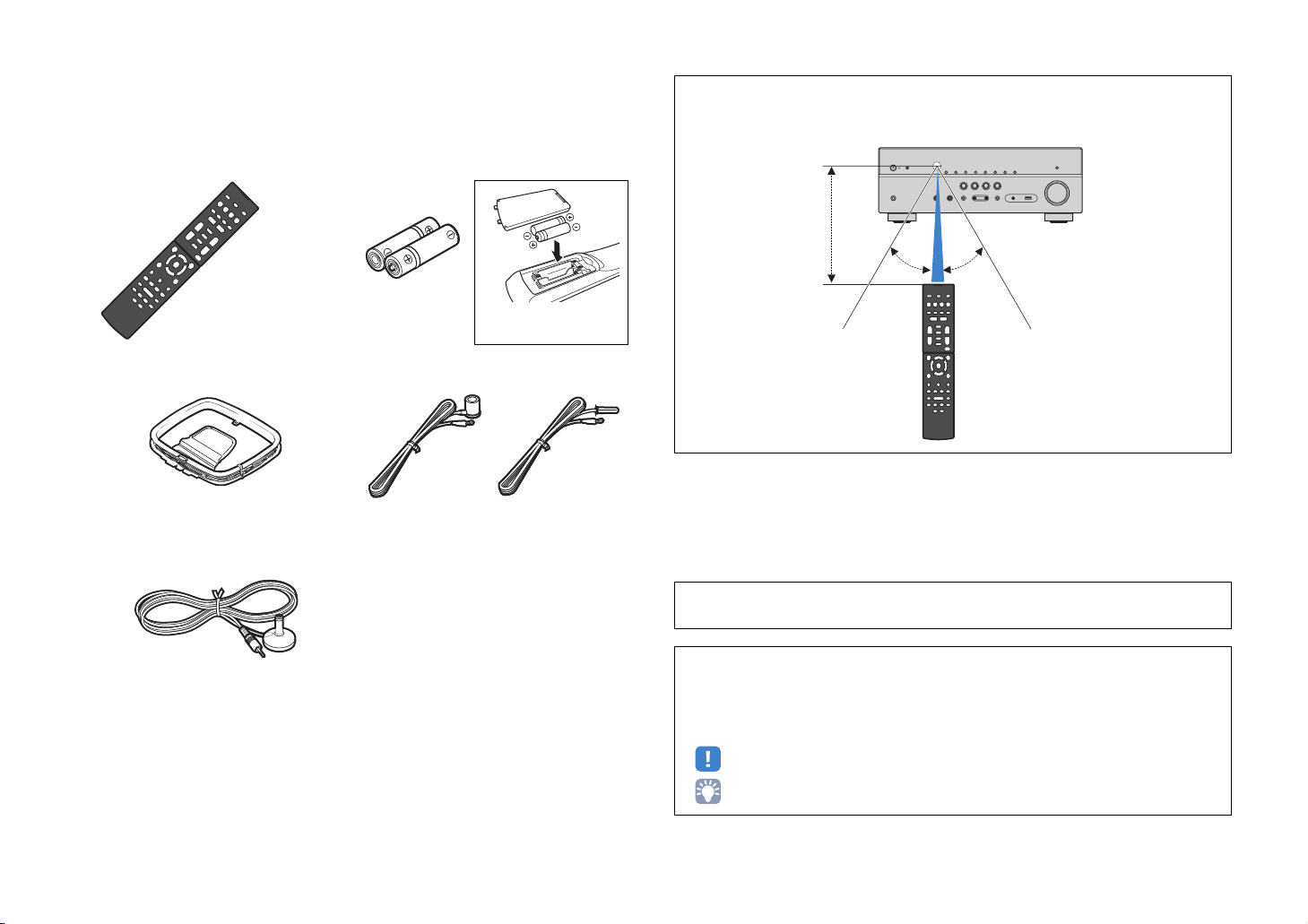
Accessories
Check that the following accessories are supplied with the product.
Remote control Batteries (AAA, R03, UM-4) (x2)
Insert the batteries the right
way round.
AM antenna FM antenna
*One of the above is supplied depending on the region of
purchase.
YPAO microphone
Operating range of the remote control
• Point the remote control at the remote control sensor on the unit and remain within the operating range
shown below.
Within 6 m (20 ft)
30° 30°
• The illustrations of the main unit used in this manual are of the RX-V579 (U.S.A. model), unless
otherwise specified.
CD-ROM (Owner’s Manual)
Easy Setup Guide
Safety Brochure
En 4
• Some features are not available in certain regions.
• Due to product improvements, specifications and appearance are subject to change without notice.
• This manual explains operations using the supplied remote control.
• This manual describes all the “iPod” and “iPhone” as the “iPod”. “iPod” refers to both “iPod” and
“iPhone” unless otherwise specified.
• indicates precautions for use of the unit and its feature limitations.
• indicates supplementary explanations for better use.
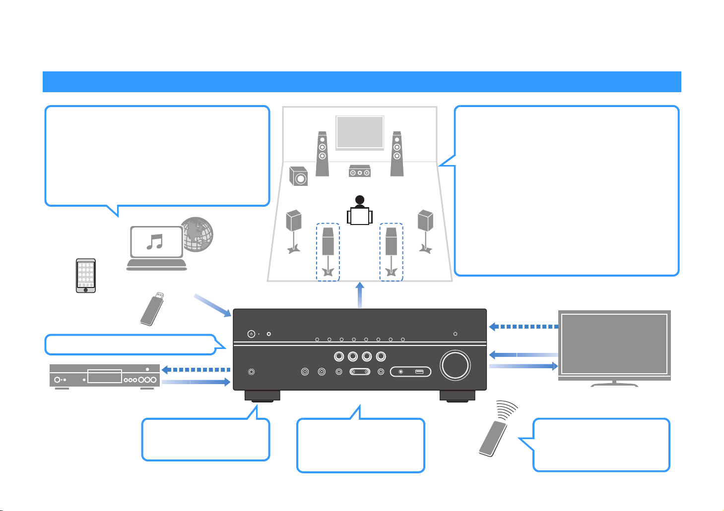
FEATURES
What you can do with the unit
Wide variety of supported content
• iPod/iPhone
•USB
• Media server (PC/NAS)
• Internet radio
•AirPlay
• BLUETOOTH
Network contents
BLUETOOTH
device
USB device
4K Ultra HD
signal and
BD/DVD player
HDCP 2.2
supported
HDMI Control
Audio/Video
. p.54
. p.59
. p.62
. p.65
. p.57
. p.53
Audio
Speakers
Audio
AV receiver (the unit)
Supports 2- to 5.1-channel (to 7.1-channel*)
speaker system. Allows you to enjoy your favorite
acoustic spaces in various styles.
• Automatically optimizing the speaker
. p.28
settings to suit your room (YPAO)
• Reproducing stereo or multichannel
. p.45
sounds with the sound fields like
actual movie theaters and concert
halls (CINEMA DSP)
• Enjoying compressed music with
**
enhanced sound (Compressed Music
Enhancer)
• Playing back music in multiple rooms
. p.48
. p.68
(Zone B)*
* RX-V579 only
HDMI Control
Audio
Audio/Video
TV
Wireless connection to a
network
. p.25
Change the input source
and favorite settings with
one touch (SCENE)
. p.43
En 5
TV remote control
Sequential operation of a TV,
AV receiver, and BD/DVD
player (HDMI Control)
. p.114

Full of useful functions!
About “AV SETUP GUIDE
”
About “AV CONTROLLER
”
❑ Connecting various devices (p.21)
A number of HDMI jacks and various input/output jacks
on the unit allow you to connect video devices (such as
BD/DVD players), audio devices (such as CD players),
game consoles, portable audio player, and other
devices.
❑ Playing back TV audio in surround sound
with a single HDMI cable connection
(Audio Return Channel: ARC) (p.19)
When using an
HDMI
cable to enable video output to the TV, audio input
from the TV, and the transmission of
signals.
ARC
-compatible TV, you only need one
HDMI
Control
❑ Creating 3-dimensional sound fields (p.45)
The Virtual Presence Speaker (VPS) function and Virtual
Surround Back Speaker (VSBS) function (RX-V579 only)
allow you to create a 3-dimensional sound field that
spreads up and deep in your own room (CINEMA DSP
3D).
❑ Surround playback with 5 speakers placed
in front (p.46)
You can enjoy the surround sound even when the
surround speakers are placed in front.
❑ Enjoying pure high fidelity sound (p.48)
When the direct playback mode is enabled, the unit
plays back the selected source with the least circuitry,
which lets you to enjoy Hi-Fi sound quality.
❑ Application for tablets “AV SETUP GUIDE”
AV SETUP GUIDE is an application that
assists you with cable connections
between AV receiver and source
devices as well as AV receiver setup.
This app guides you through the various
settings such as speaker connections,
TV and source device connections and
assigning the power amp.
Functions:
1) Connection support guide
– Speaker connection
– TV/source devices connection
2) Setup support guide
– Automatic network setup of HDMI, power amp
assign, etc.
– Various setup assistance with illustrations.
– YPAO setting guidance
3) View owner’s manual
* This application is for tablets only.
For details, search for “AV SETUP GUIDE” on the App
Store or Google Play.
❑ Application for smartphone / tablets “AV
CONTROLLER”
AV CONTROLLER provides you the
flexibility to control the available inputs,
volume, mute and power commands. It
lets users change a song from Internet
Radio, USB and command FM/AM
tuners or any other internally available
source.
Functions:
– Power on/off
– Volume up/down
–Mute
– Music Play
– Input Selection
– DSP Mode Selection
– SCENE selection
– Blu-ray player fundamental control
– Seamless control between the Yamaha AV receiver
and Blu-ray player
– Demo mode — Explains how to use this app
For details, search for “AV CONTROLLER” on the App
Store or Google Play.
❑ Low power consumption
The ECO mode (power saving function) reduces the
unit’s power consumption and helps to create an
eco-friendly home theater system (p.89).
En 6
Part names and functions
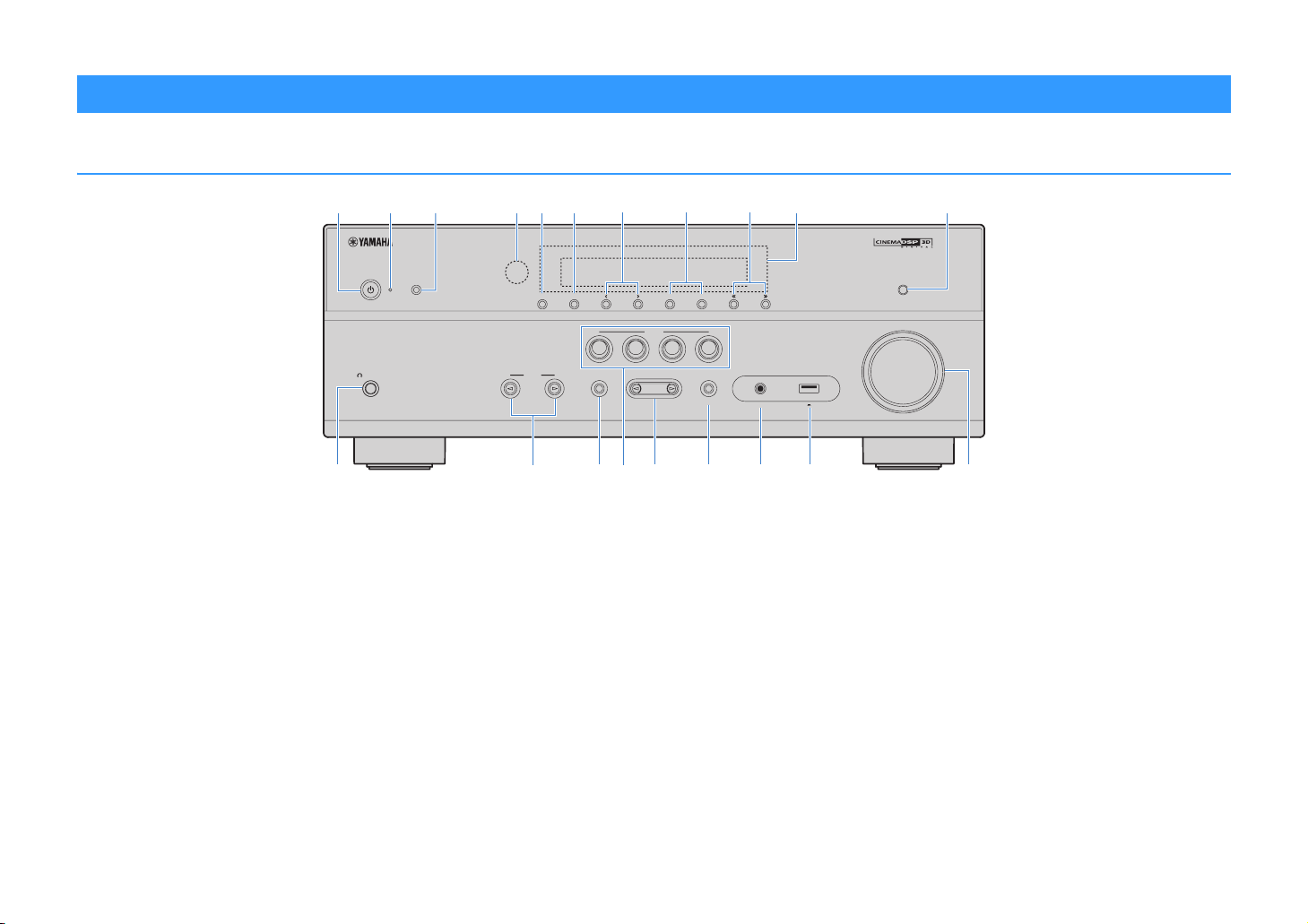
Front panel
b cdfgheaji k
PHONES
SILENT CINEMA
lmnoprstq
1 z (power) key
Turns on/off (standby) the unit.
2 Standby indicator
Lights up when the unit is in standby mode under any of the
following conditions.
• HDMI Control is enabled (p.84)
• Standby Through is enabled (p.84)
• Network Standby is enabled (p.93)
• An iPod is being charged (p.54)
3 YPAO MIC jack
For connecting the supplied YPAO microphone (p.28).
4 Remote control sensor
Receives remote control signals (p.4).
5 INFO (WPS) key
Selects the information displayed on the front display (p.71).
Enters the wireless LAN connection setup (WPS button
configuration) by holding down for 3 seconds (p.35).
YPAO MIC
INFO (WPS)
MEMORY
PRESET
FM AM TUNING
SCENE
BD
DVD
INPUT
TONE CONTROL
NET
TV
PROGRAM
RADIO
STRAIGHT
(CONNECT)
AUX
AUDIO
6 MEMORY key
Registers FM/AM radio stations as preset stations (p.50).
7 PRESET keys
Select a preset FM/AM radio station (p.51).
8 FM and AM keys
Switch between FM and AM (p.49).
9 TUNING keys
Select the radio frequency (p.49).
0 Front display
Displays information (p.8).
A DIRECT key
Enables/disables the direct playback mode (p.48).
B PHONES jack
For connecting headphones.
C INPUT keys
Select an input source.
DIRECT
VOLUME
5V 1A
D TONE CONTROL key
Adjusts the high-frequency range and low-frequency range
of output sounds (p.73).
E SCENE keys
Select the registered input source and sound program with
one touch. Also, turns on the unit when it is in standby mode
(p.43).
F PROGRAM keys
Select a sound program or a surround decoder (p.44).
G STRAIGHT key
Enables/disables the straight decode mode (p.47).
H AUX jack
For connecting devices, such as portable audio players
(p.24).
I USB jack
For connecting a USB storage device (p.59) or an iPod
(p.54).
J VOLUME knob
Adjusts the volume.
En 7
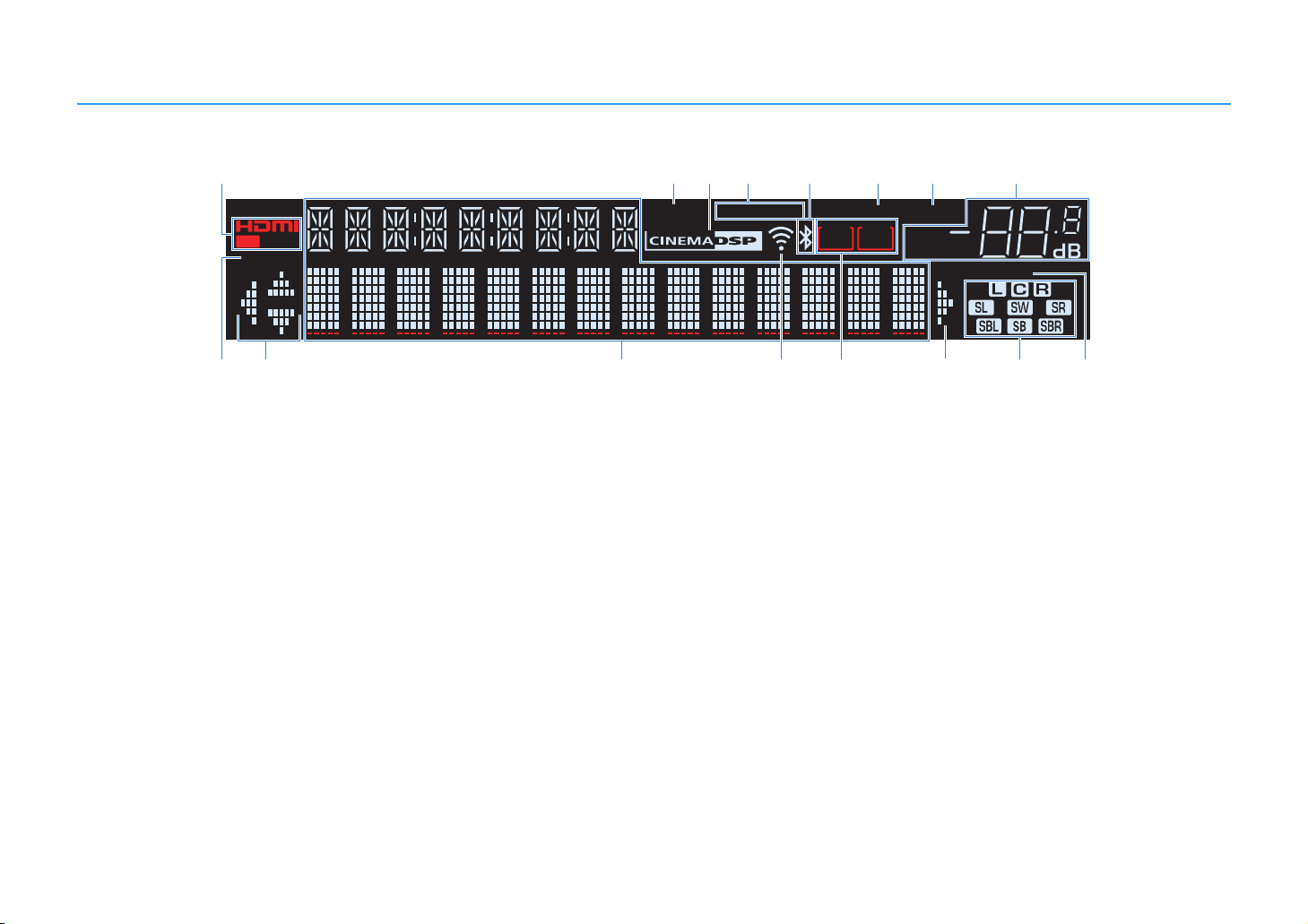
Front display (indicators)
a
CHARGE
1 2
OUT
ECO
ji ljkmno
1 HDMI
Lights up when HDMI signals are being input or output.
OUT
Lights up when HDMI signals are being output.
2 ENHANCER
Lights up when Compressed Music Enhancer (p.48) is
working.
3 CINEMA DSP
Lights up when CINEMA DSP (p.45) or CINEMA DSP 3D
(p.45) is working.
4 STEREO
Lights up when the unit is receiving a stereo FM radio signal.
TUNED
Lights up when the unit is receiving an FM/AM radio station
signal.
5 BLUETOOTH indicator
Light up while the unit is connecting to a BLUETOOTH
device.
6 SLEEP
Lights up when the sleep timer is on.
bc d
ENHANCER
7 MUTE
Blinks when audio is muted.
8 Volume indicator
Indicates the current volume.
9 ECO
Lights up when the eco mode (p.89) is enabled.
0 Cursor indicators
Indicate the remote control cursor keys currently operational.
A Information display
Displays the current status (such as input name and sound
mode name). You can switch the information by pressing
INFO (p.71).
B Signal strength indicator
Indicates the strength of the wireless signal (p.32).
C ZONE indicators (RX-V579 only)
Indicate the zone to which the sound is output (p.69).
STEREO
TUNED
e
PARTY
ZONEAZONE
23
fg h
SLEEP
MUTE
B
VOL.
ADAPTIVE DRC
D Speaker indicators
Indicate speaker terminals from which signals are output.
A Front speaker (L)
S Front speaker (R)
D Center speaker
F Surround speaker (L)
G Surround speaker (R)
H Surround back speaker (L)*
J Surround back speaker (R)*
K Surround back speaker*
L Subwoofer
* RX-V579 only
E ADAPTIVE DRC
Lights up when Adaptive DRC (p.73) is working.
VIRTUAL
En 8
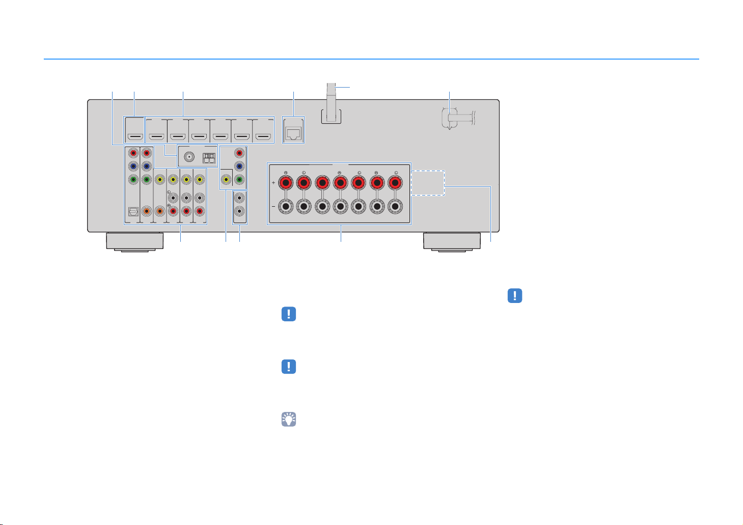
Rear panel
ab cd f
HDMIOUT
HDCP2.2
P
R
P
B
Y
COMPONENT
VIDEO
OPTICAL
(TV)
AV1
HDMI1
HDMI2
(BD/DVD)
ARC
VIDEO
COAXIAL
COAXIAL
AV2
AV5
AV4
AV3
FM
75Ω
HDMI3
ANTENNA
(RADIO)
HDMI4
AM
AV6
gh
1 ANTENNA jacks
For connecting to FM and AM antennas (p.24).
2 HDMI OUT jack
For connecting to an HDMI-compatible TV and outputting
video/audio signals (p.19). When using ARC, TV audio signal
can also be input through the HDMI OUT jack.
3 HDMI 1–6 jacks
For connecting to HDMI-compatible playback devices and
inputting video/audio signals (p.21).
4 NETWORK jack
For a wired connection to a network (p.25).
5 Wireless antenna
For a wireless (Wi-Fi) connection to a network (p.25).
6 Power cable
For connecting to an AC wall outlet (p.26).
COMPONENT
VIDEO
VIDEO
MONITOROUT
e
(RX-V579 U.S.A. model)
* The area around the video/audio output jacks is
marked in white on the actual product to prevent
improper connections.
0 SPEAKERS terminals
For connecting to speakers (p.16).
• The SURROUND BACK/BI AMP/ZONE B jacks are available on
RX-V579 only.
A VOLTAGE SELECTOR
(Taiwan and General models only)
Selects the switch position according to your local voltage
(p.26).
CENTER
WSS
SPEAKERS
SURROUND
SURROUNDBACK/BIAMP
/ZONEB
SINGLE
N
ETWORK
HDMI6
HDMI5
HDCP2.2
P
R
P
B
Y
1
2
SUBWOOFER
PREOUT
(NET)
FRONT
ji k
7 AV jacks
AUDIO jacks (RX-V479)
For connecting to video/audio playback devices and
inputting video/audio signals (p.21).
• The COMPONENT jacks are available on RX-V579 only.
8 MONITOR OUT jacks
For connecting to a TV and outputting video signals (p.19).
• The COMPONENT jacks are available on RX-V579 only.
9 SUBWOOFER PRE OUT jack
For connecting to a subwoofer (with built-in amplifier) (p.16).
• (RX-V579 only)
You can connect 2 subwoofers (with built-in amplifier) to the
unit.
En 9
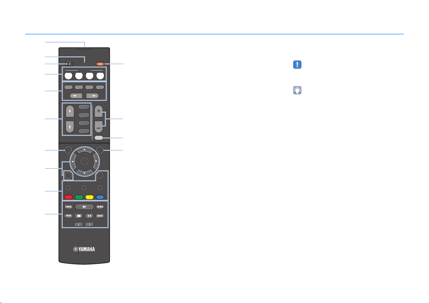
Remote control
a
b
c
d
e
f
g
h
i
j
ZONE A ZONE B
SCENE
BD
TV
DVD
STRAIGHT
DIRECT ENHANCER BASS
PROGRAM
FM/AM
INPUT
BLUETOOTH
SETUP
TOP MENU HOME
RED
MEMORY
TUNING
PRESET
SLEEP
USB
NET
ENTER
YELLOWGREEN
NET
POP-UP/MENU
RADIO
VOLUME
MUTE
OPTION
DISPLAYRETURN
BLUE
TUNING
k
l
m
n
1 Remote control signal transmitter
Transmits infrared signals.
2 SLEEP key
Switches the unit to standby mode automatically after a
specified period of time has elapsed (sleep timer). Press
repeatedly to set the time (120 min, 90 min, 60 min, 30 min,
off).
3 ZONE switch (RX-V579 only)
Enable/disable the audio output to Zone A or Zone B (p.69).
4 SCENE keys
Select the registered input source and sound program with
one touch. Also, turn on the unit when it is in standby mode
(p.43).
5 Sound mode keys
Select a sound mode (p.44).
6 Input selection keys
Select an input source for playback.
You can select directly each input source by pressing the
following keys.
FM/AM FM/AM radio
USB USB jack (on the front panel)
NET SERVER, NET RADIO, AirPlay and network
sources (press repeatedly to select a desired
source)
BLUETOOTH BLUETOOTH device
7 SETUP key
Displays the setup menu (p.76).
8 Menu operation keys
Cursor keys Select a menu or a parameter.
ENTER Confirms a selected item.
RETURN Returns to the previous screen.
890 External device operation keys
Let you perform playback operations when “USB” or “NET”
is selected as the input source, or control playback of the
HDMI Control-compatible playback device.
• The playback devices must support HDMI Control. However,
Yamaha does not assure the operation of all HDMI
Control-compatible devices.
• You can assign the unit’s functions to the RED/GREEN/
YELLOW/BLUE keys (p.91).
0 Radio keys
Operate the FM/AM radio when “TUNER” is selected as the
input source (p.49).
MEMORY Registers FM/AM radio stations as presets.
PRESET Select a preset station.
TUNING Select the radio frequency.
A z (receiver power) key
Turns on/off (standby) the unit.
B VOLUME keys
Adjust the volume.
C MUTE key
Mutes the audio output.
D OPTION key
Displays the option menu (p.72).
(RX-V579)
En 10

PREPARATIONS
General setup procedure
1 Placing speakers (p.12)
2 Connecting speakers (p.16)
3 Connecting a TV (p.19)
4 Connecting playback devices (p.21)
5 Connecting the FM/AM antennas (p.24)
Preparing for connecting to a network
6
(p.25)
7 Connecting the power cable (p.26)
Selecting an on-screen menu language
8
(p.27)
Optimizing the speaker settings
9
automatically (YPAO) (p.28)
Select the speaker layout for the number of speakers that you are using and place them in your room.
Connect the speakers to the unit.
Connect a TV to the unit.
Connect video devices (such as BD/DVD players) and audio devices (such as CD players) to the unit.
Connect the supplied FM/AM antennas to the unit.
Connect the unit to a network with a commercially-available network cable.
After all the connections are complete, plug in the power cable.
Select the desired on-screen menu language.
Optimize the speaker settings, such as volume balance and acoustic parameters, to suit your room
(YPAO).
10 Connecting to a network wirelessly (p.32)
This completes all the preparations. Enjoy playing movies, music, radio and other content with the unit!
Connect the unit to a network wirelessly.
En 11

1 2 3 4 5 6 7 8 9 10
1 Placing speakers
Select the speaker layout for the number of speakers that you are using and place the speakers and subwoofer in your room. This section describes the representative speaker layout
examples.
Caution
• (U.S.A. and Canada models only)
Under its default settings, the unit is configured for 8-ohm speakers. When connecting 6-ohm speakers, set the unit’s speaker impedance to “6 Ω MIN”. For details, see “Setting the speaker impedance” (p.15).
• (Except for U.S.A. and Canada models)
Use speakers with an impedance of at least 6 Ω.
• Use a subwoofer with built-in amplifier.
• Be sure to connect the front left and right speakers.
Speaker system (the number of channels)
Speaker type Abbr. Function
Front (L) 1
Front (R) 2 ●●●●●●●
Produce front left/right channel sounds (stereo sounds).
7.1*16.1*
●●●●●●●
1
5.1
Center 3 Produces center channel sounds (such as movie dialogue and vocals). ●●●● ●
Surround (L) 4
Surround (R) 5 ●●●
Surround back (L)*
Surround back (R)*
Surround back*
1
1
1
Subwoofer 9
Produce surround left/right channel sounds.
6
Produce surround back left/right channel sounds.
7 ●
8 Produces sounds mixed from surround back left/right channel sounds. ●
Produces LFE (low-frequency effect) channel sounds and reinforces the bass parts of other channels.
This channel is counted as “0.1”.
●●●
●
●●●●●●●
5.1
(Virtual
CINEMA
FRONT)
2
●*
2
●*
4.1 3.1 2.1
●
●
*1 RX-V579 only
*2 Place the surround speakers in front and set “Virtual CINEMA FRONT” (p.82) in the “Setup” menu to “On”.
• RX-V579 supports 2- to 7.1-channel system, and RX-V479 supports 2- to 5.1-channel speaker system.
• (RX-V579 only)
You can connect two subwoofers (with built-in amplifier) to the unit. Two subwoofers connected to the unit output the same sounds.
En 12
1 2 3 4 5 6 7 8 9 10
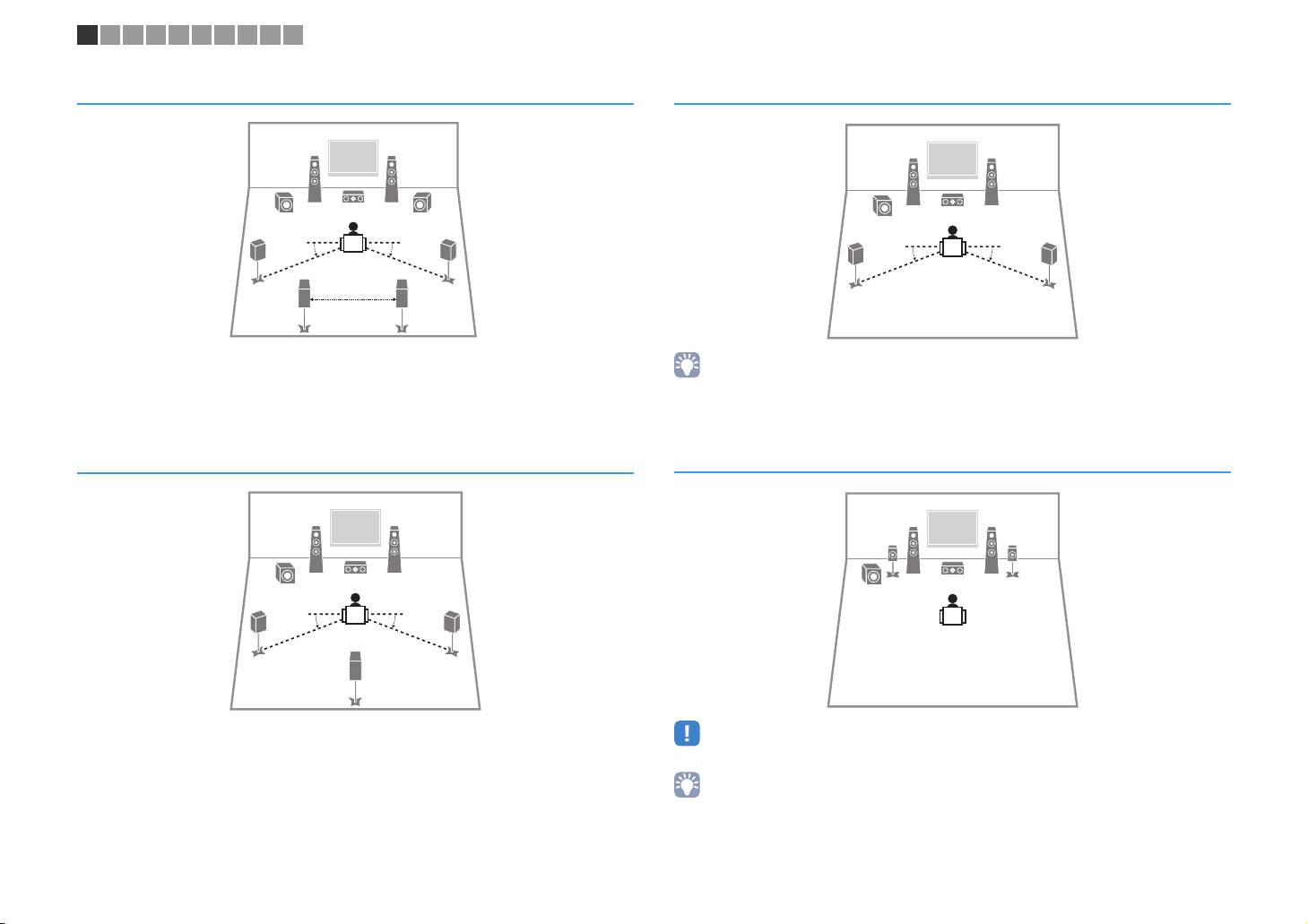
7.1-channel system (
45
6.1-channel system (
45
RX-V579
1
67
30 cm (1 ft) or more
RX-V579
1
only)
2
399
10° to 30°10° to 30°
only)
2
39
10° to 30°10° to 30°
8
5.1-channel system
12
39
45
10° to 30°10° to 30°
• You can enjoy surround sound even without the center speaker (front 4.1-channel system).
• You can place the subwoofer either in the left or right side.
5.1-channel system (
Virtual CINEMA FRONT
12
45
39
)
• To utilize this configuration, set “Virtual CINEMA FRONT” (p.82) in the “Setup” menu to “On”.
• You can enjoy surround sound even without the center speaker (front 4.1-channel system).
• You can place the subwoofer either in the left or right side.
En 13
1 2 3 4 5 6 7 8 9 10
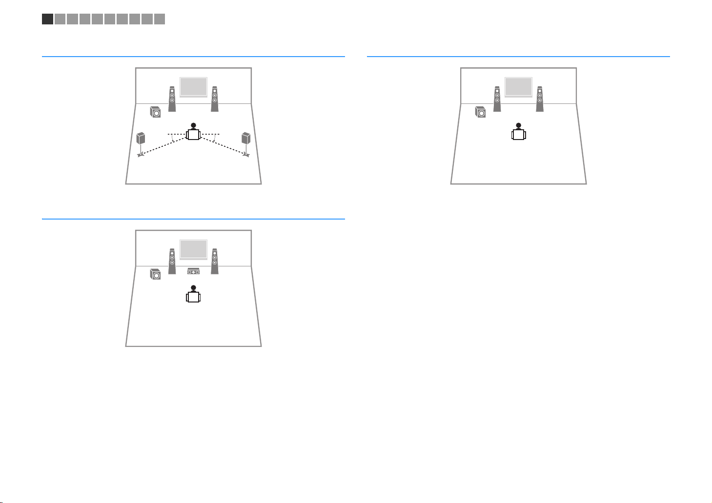
4.1-channel system
45
3.1-channel system
12
9
12
39
2.1-channel system
12
9
10° to 30°10° to 30°
En 14

1 2 3 4 5 6 7 8 9 10
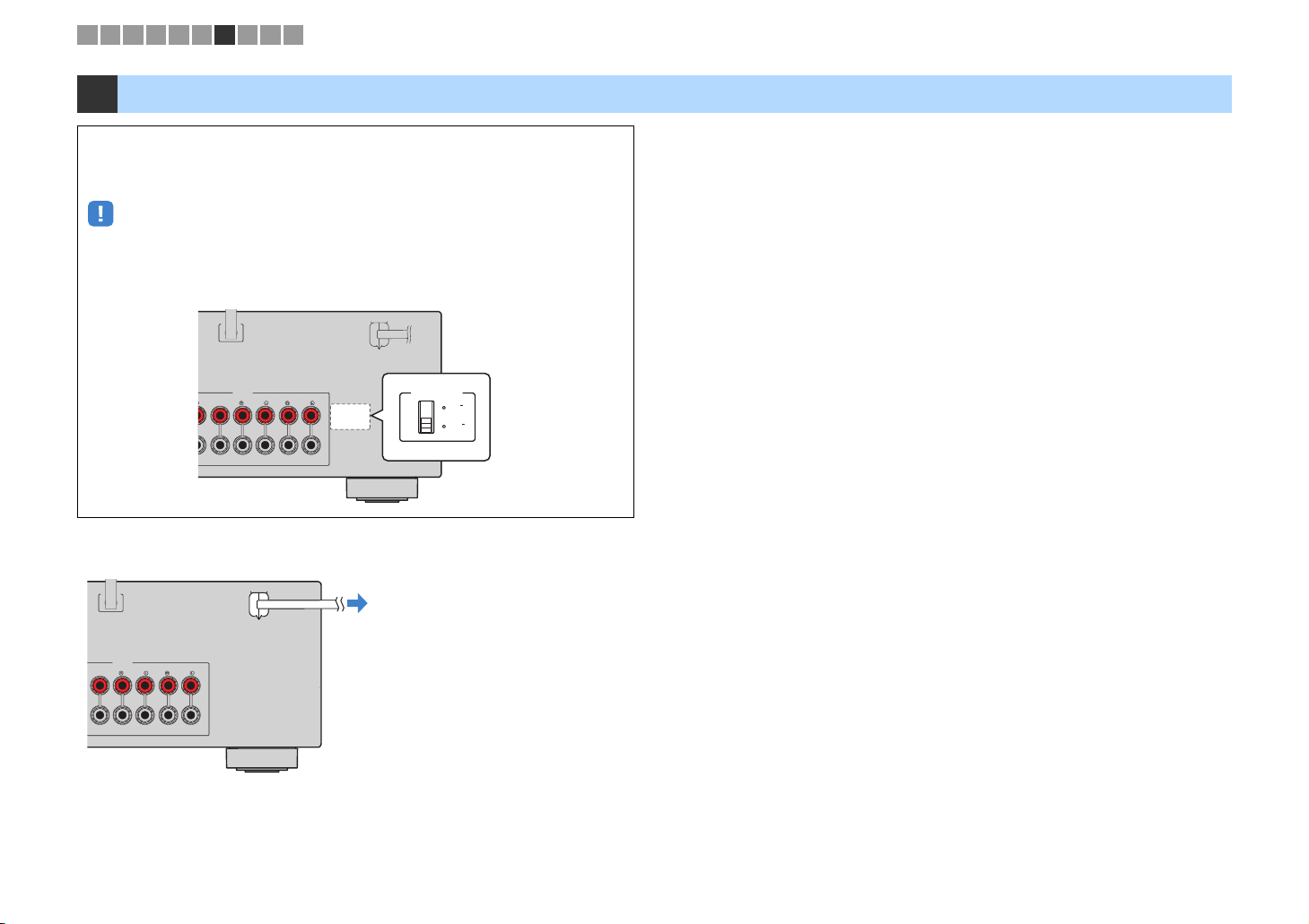
■ Setting the speaker impedance
(U.S.A. and Canada models only)
Under its default settings, the unit is configured for 8-ohm speakers. When connecting
6-ohm speakers, set the speaker impedance to “6 Ω MIN”.
Before connecting speakers, connect the power cable to an AC wall
1
outlet.
While holding down STRAIGHT on the front panel, press z (power).
2
z (power)
STRAIGHT
Check that “SP IMP.” is displayed on the front display.
3
SLEEP
CHARGE
OUT
ECO
1 2
ENHANCER
STEREO
TUNED
PARTY
ZONE2AZONE
MUTE
3B
VOL.
VIRTUAL
ADAPTIVE DRC
SP IMP.••8¬MIN
Press STRAIGHT to select “6 Ω MIN”.
4
Press z (power) to set the unit to standby mode and remove the
5
power cable from the AC wall outlet.
You are now ready to connect the speakers.
En 15
FRONT CENTER SURROUND
SINGLE
SURROUND BACK/BI AMP
/ZONE B
OR OUT
P
B
Y
SPEAKERS
SUBWOOFER
PRE OUT
2
1
DC OUT
5V 0.5A
FRONT CENTER SURROUND
SINGLE
SURROUND BACK/BI AMP
/ZONE B
OR OUT
P
B
Y
SPEAKERS
SUBWOOFER
PRE OUT
2
1
DC OUT
5V 0.5A
1 2 3 4 5 6 7 8 9 10
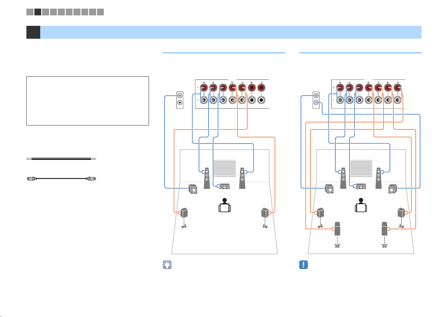
2 Connecting speakers
Connect the speakers placed in your room to the unit.
The following diagrams provide connections for 5.1and 7.1-channel systems as examples. For other
systems, connect speakers while referring to the
connection diagram for the 5.1-channel system.
Caution
• Remove the unit’s power cable from an AC wall outlet and turn
off the subwoofer before connecting the speakers.
• Ensure that the core wires of the speaker cable do not touch
one another or come into contact with the unit’s metal parts.
Doing so may damage the unit or the speakers. If the speaker
cables short circuit, “Check SP Wires” will appear on the front
display when the unit is turned on.
Cables required for connection
(commercially available)
Speaker cables (x the number of speakers)
+
–
+
–
Audio pin cable (x1: for connecting a subwoofer)
5.1-channel system 7.1-channel system
(RX-V579 only)
The unit (rear)
12
9
3
45
The unit (rear)
1
9
3
45
67
2
9
• (RX-V579 only)
You can connect 2 subwoofers (with built-in amplifier) to the unit.
The 2 subwoofers output the same sound.
• When using only one surround back speaker, connect it to the
SINGLE jack (L side).
En 16
1 2 3 4 5 6 7 8 9 10
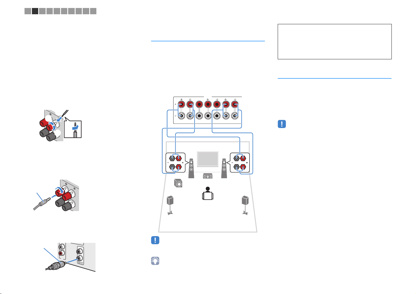
■ Connecting speaker cables
Speaker cables have two wires. One is for connecting
the negative (-) terminal of the unit and the speaker, and
the other is for the positive (+) terminal. If the wires are
colored to prevent confusion, connect the black wire to
the negative and the other wire to the positive terminal.
a Remove approximately 10 mm (3/8”) of insulation from
the ends of the speaker cable and twist the bare wires of
the cable firmly together.
b Loosen the speaker terminal.
c Insert the bare wires of the cable into the gap on the side
(upper right or bottom left) of the terminal.
d Tighten the terminal.
+ (red)
— (black)
Using a banana plug
(U.S.A., Canada, China, Australia, Taiwan and General
models only)
a Tighten the speaker terminal.
b Insert a banana plug into the end of the terminal.
Banana plug
b
d
a
c
aa
Connecting front speakers that
support bi-amp connections
Caution
• Before making bi-amp connections, remove any brackets or
(RX-V579 only)
When using front speakers that support bi-amp
connections, connect them to the FRONT jacks and
SURROUND BACK/BI-AMP/ZONE B jacks.
To enable the bi-amp function, set “Power Amp Assign”
(p.80) in the “Setup” menu to “BI-AMP” after connecting
the power cable to an AC wall outlet.
The unit (rear)
FRONT CENTER SURROUND
SPEAKERS
SURROUND BACK/BI AMP
/ZONE B
SINGLE
Connecting
(RX-V579 only)
The Zone A/B function allows you to playback an input
source in the room where the unit is installed (Zone A)
and in another room (Zone B). To connect the Zone B
speakers, see “Playing back music in multiple rooms
(RX-V579 only)” (p.68).
• Surround back speakers or bi-amplified front speakers cannot be
used while the Zone B function is enabled.
12
9
45
3
cables that connect a woofer with a tweeter. Refer to the
instruction manual of the speakers for details. If you are not
making bi-amp connections, make sure that the brackets or
cables are connected before connecting the speaker cables.
Zone B
speakers
b
■ Connecting the subwoofer
(with built-in amplifier)
Use an audio pin cable to connect the subwoofer.
Audio pin cable
AV 6
1
2
• Surround back speakers or Zone B speakers cannot be used during
bi-amp connections.
• The FRONT jacks and SURROUND BACK/BI-AMP/ZONE B jacks
output the same signals.
En 17
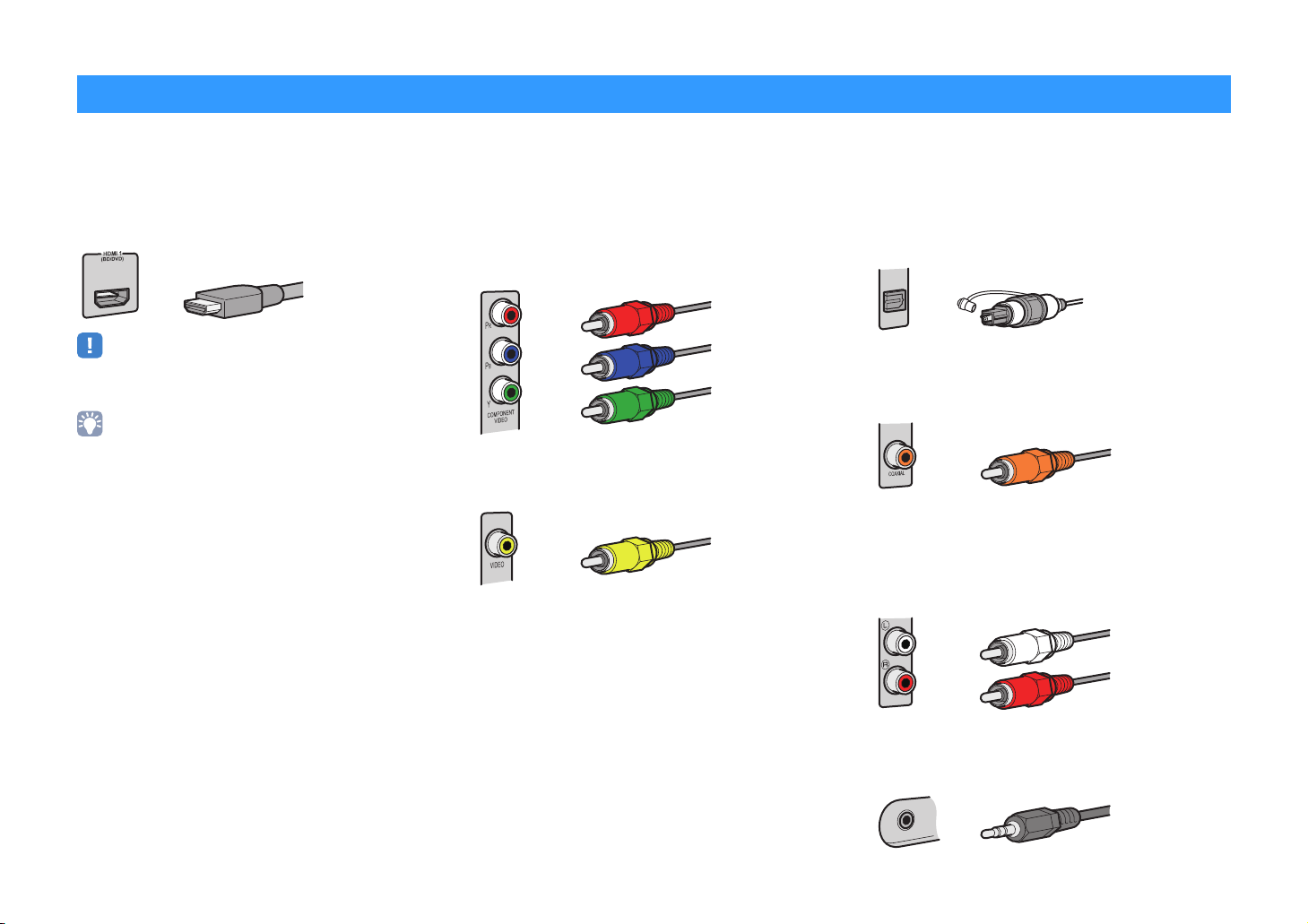
Input/output jacks and cables
■ Video/audio jacks
❑ HDMI jacks
Transmit digital video and digital sound through a single
jack. Use an HDMI cable.
HDMI cable
• Use a 19-pin HDMI cable with the HDMI logo. We recommend using
a cable less than 5.0 m (16.4 ft) long to prevent signal quality
degradation.
• The unit’s HDMI jacks support the HDMI Control, Audio Return
Channel (ARC), and 3D and 4K Ultra HD video transmission
(through output) features.
• Use high speed HDMI cables to enjoy 3D or 4K Ultra HD videos.
■ Video jacks
❑ COMPONENT VIDEO jacks (RX-V579 only)
Transmit video signals separated into three
components: luminance (Y), chrominance blue (P
and chrominance red (P
cable with three plugs.
R). Use a component video
Component video cable
❑ VIDEO jacks
Transmit analog video signals. Use a video pin cable.
Video pin cable
B),
■ Audio jacks
❑ OPTICAL jacks
Transmit digital audio signals. Use a digital optical
cable. Remove the tip protector (if available) before
using the cable.
Digital optical cable
OPTICAL
❑ COAXIAL jacks
Transmit digital audio signals. Use a digital coaxial
cable.
Digital coaxial cable
❑ AUDIO jacks
(Stereo L/R jacks)
Transmit analog stereo audio signals. Use a stereo pin
cable (RCA cable).
Stereo pin cable
En 18
(Stereo mini jack)
Transmits analog stereo audio signals. Use a stereo
mini-plug cable.
Stereo mini-plug cable
1 2 3 4 5 6 7 8 9 10
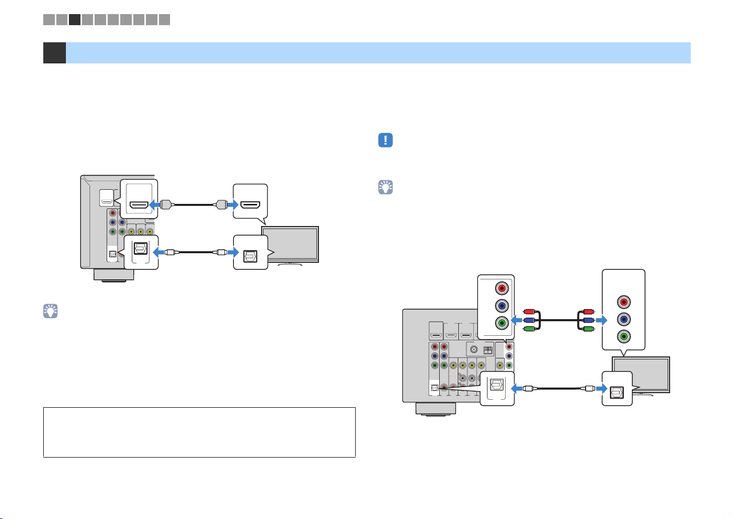
3 Connecting a TV
Connect a TV to the unit so that video input to the unit can be output to the TV. You can
also enjoy playback of TV audio on the unit.
To maximize the performance of the unit, we recommend connecting a TV with an HDMI
cable.
■ HDMI connection
Connect the TV to the unit with an HDMI cable and a digital optical cable.
The unit (rear)
HDMI OUT jack
OUT
HDMI
HDCP2.2
HDMI 2
HDMI
HDMI 1
(
)
OUT
HDMI
BD/DVD
HDCP2.2
ARC
P
R
P
B
Y
COMPONENT
VIDEO
OPTICAL
(
TV
AV 1
)
COAXIAL COAXIAL
AV 2
VIDEO
AV 3
ARC
HDMI
A
OPTICAL
(TV)
AV 4
AV 1
(RX-V579)
AV 1 (OPTICAL) jack
(RX-V479)
AUDIO 1 (OPTICAL) jack
OO
AV 5
• You do not make a digital optical cable connection between the TV and the unit in the following cases:
– If your TV supports Audio Return Channel (ARC)
– If you will receive TV broadcasts only from the set-top box
• If you connect a TV that supports HDMI Control to the unit with an HDMI cable, you can control the unit’s
power and volume with the TV’s remote control.
To use HDMI Control and ARC, you need to configure the HDMI settings on the unit. For
details on the settings, see “Information on HDMI” (p.114).
About Audio Return Channel (ARC)
• ARC allows audio signals to travel both ways. If you connect a TV that supports ARC to the unit with a
single HDMI cable, you can output video/audio to the TV or input TV audio to the unit.
• When using ARC, connect a TV with an HDMI cable that supports ARC.
HDMI input
HDMI
HDMI
OPTICAL
Audio output
(digital optical)
TV
■ Component (RX-V579) / composite video connection
When connecting any video device with a component video cable, connect the TV to
the MONITOR OUT (COMPONENT VIDEO) jacks.
When connecting any video device with a video pin cable, connect the TV to the
MONITOR OUT (VIDEO) jack.
• If you connect your TV to the unit with a cable other than HDMI, video input to the unit via HDMI cannot be
output to the TV.
• Operations with TV screen are available only when your TV is connected to the unit via HDMI.
• If you will receive TV broadcasts only from the set-top box, you do not need to make an audio cable
connection between the TV and the unit.
❑ COMPONENT VIDEO connection (RX-V579 only)
Connect the TV to the unit with a component video cable and a digital optical cable.
Video input
(component video)
COMPONENT
VIDEO
PR
PB
P
R
P
B
Y
Y
OPTICAL
O
Audio output
(digital optical)
TV
The unit (rear)
HDMIOUT
HDCP2.2
ARC
P
R
P
B
Y
COMPONENT
VIDEO
OPTICAL
(TV)
AV1
MONITOR OUT
(COMPONENT VIDEO) jacks
COMPONENT
VIDEO
PR
PB
HDMI5
HDMI1
(BD/DVD)
VIDEO
COAXIAL
COAXIAL
AV3
AV2
AV4
HDMI4
HDMI3
HDMI2
AV5
ANTENNA
FM
75Ω
(RADIO)
AV6
Y
MONITOR OUT
COMPONENT
AM
VIDEO
OPTICAL
(TV)
AV 1
VIDEO
P
P
MONITOROUT
R
B
Y
SUBWOOFER
PREOUT
1
2
AV 1 (OPTICAL) jack
P
R
P
B
Y
O
En 19
1 2 3 4 5 6 7 8 9 10
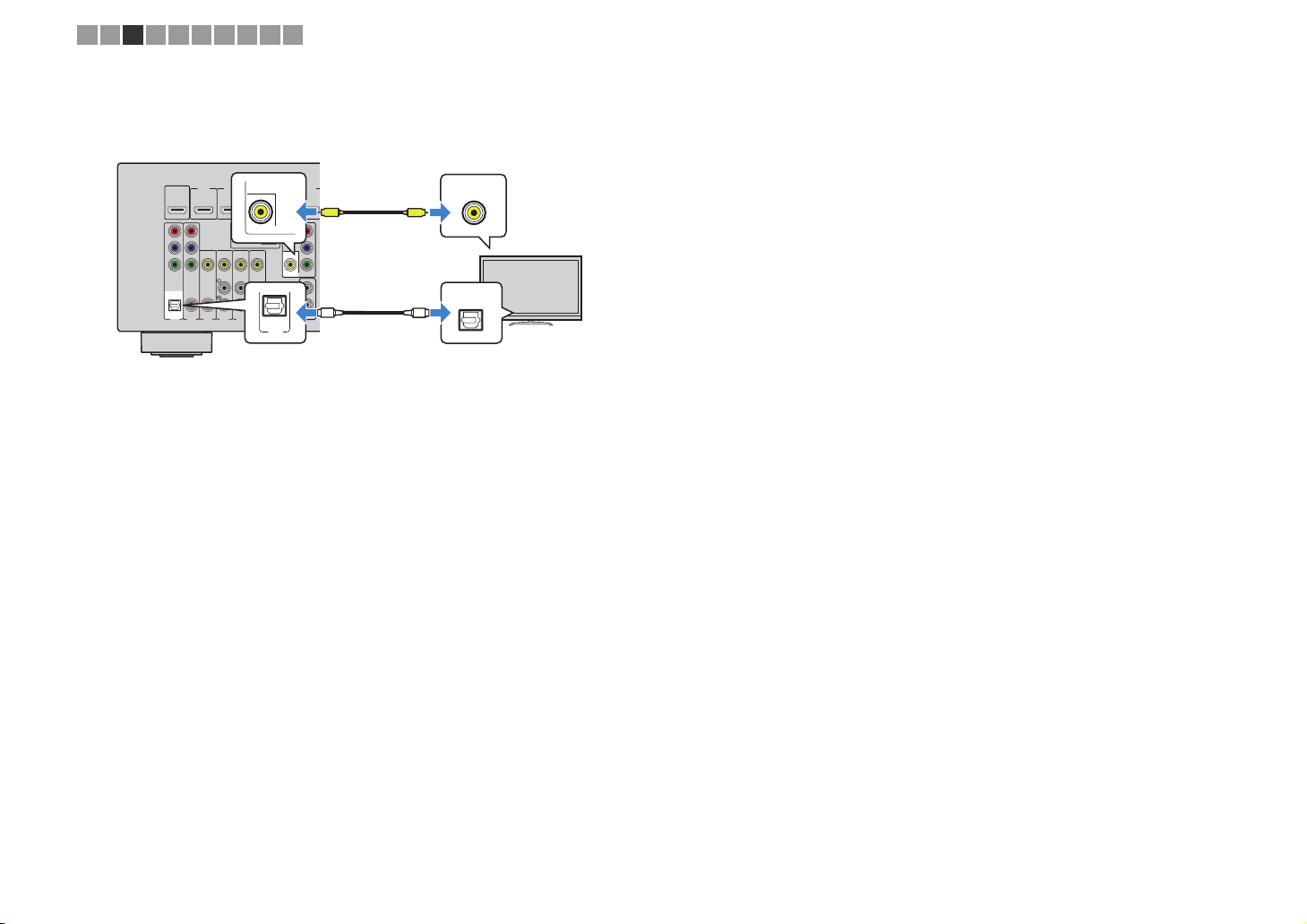
❑ VIDEO (composite video) connection
Connect the TV to the unit with a video pin cable and a digital optical cable.
The unit (rear)
HDMIOUT
HDCP2.2
ARC
P
R
P
B
Y
COMPONENT
VIDEO
OPTICAL
(TV)
AV1
MONITOR OUT
(VIDEO) jack
HDMI2
HDMI1
(BD/DVD)
ANTENNA
(RADIO)
FM
75Ω
VIDEO
COAXIAL
COAXIAL
AV5
AV4
AV3
AV2
AV 1 (OPTICAL) jack
AUDIO 1 (OPTICAL) jack
HDMI3
HDMI4
COMPONENT
AM
MONITOR OUT
AV6
OPTICAL
(TV)
AV 1
(RX-V579)
(RX-V479)
VIDEO
VIDEO
MONITOROUT
P
P
R
B
Y
SUBWOOFER
PREOUT
Video input
(composite video)
HDMI5
V
1
2
O
VIDEO
V
OPTICAL
O
TV
Audio output
(digital optical)
En 20
1 2 3 4 5 6 7 8 9 10
4 Connecting playback devices
The unit is equipped with a variety of input jacks including HDMI input jacks to allow
you to connect different types of playback devices. For information on how to connect a
BLUETOOTH device, an iPod, or a USB storage device, see the following pages.
– Connecting a BLUETOOTH device (p.53)
– Connecting an iPod (p.54)
– Connecting a USB storage device (p.59)
Connecting video devices (such as BD/
DVD
players)
Connect video devices such as BD/DVD players, set-top boxes (STBs) and game
consoles to the unit. Depending on the video/audio output jacks available on your video
device, choose one of the following connections. We recommend using an HDMI
connection if the video device has an HDMI output jack.
• If the combination of video/audio input jacks available on the unit does not match your video device, change
its combination according to the output jacks of your device (p.22).
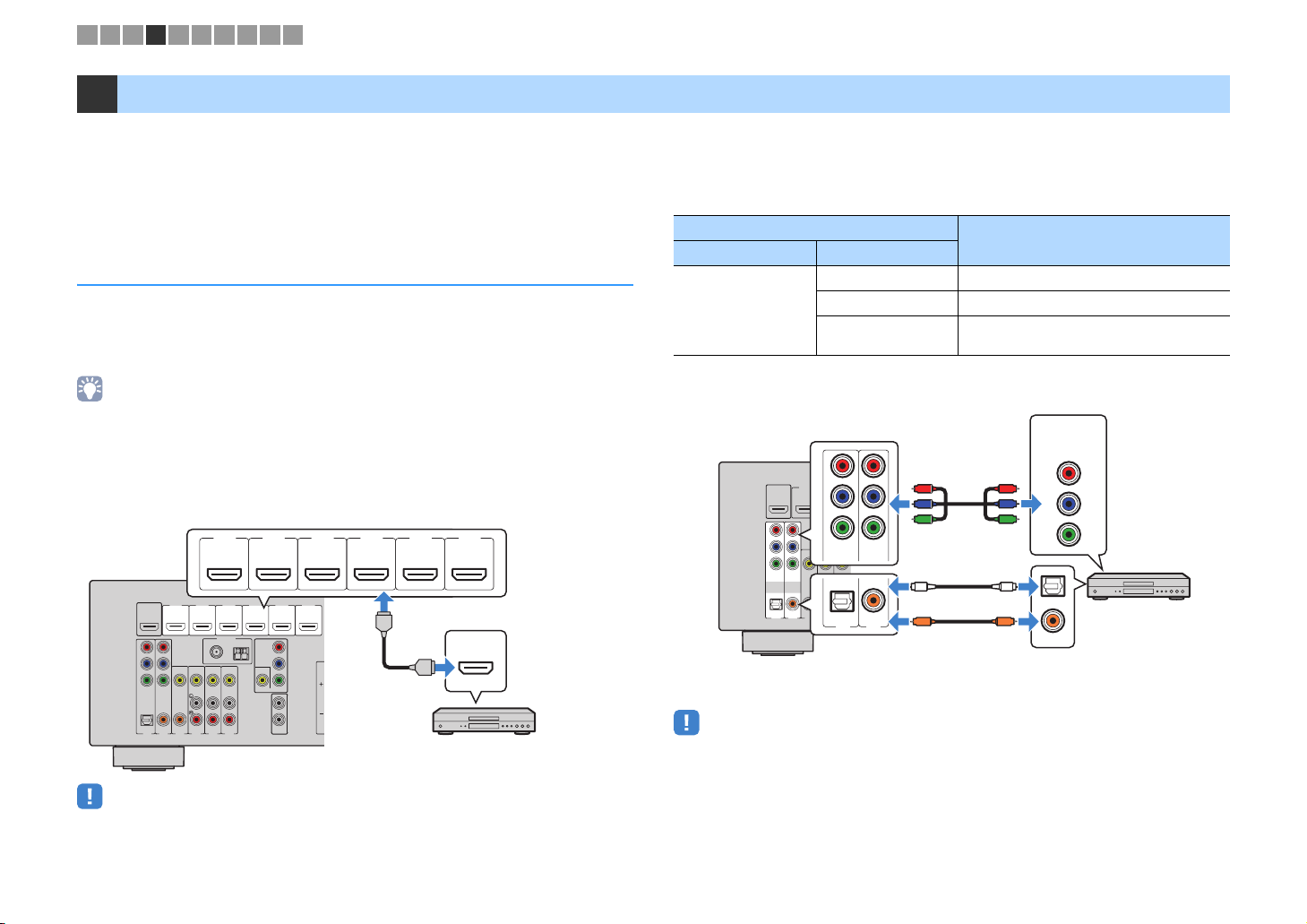
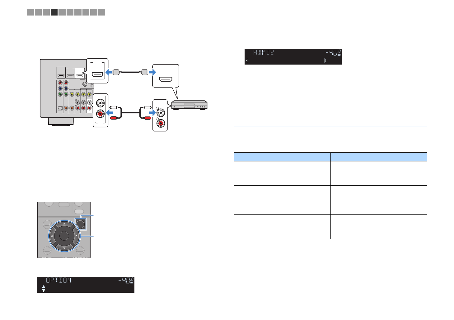
■ HDMI connection
Connect a video device to the unit with an HDMI cable.
HDMI 1–6 jacks
HDMI 1
HDMI 2 HDMI 3 HDMI 4
(
)
BD/DVD
The unit (rear)
HDMI4
COMPONENT
VIDEO
VIDEO
MONITOROUT
P
P
R
B
Y
HDMI5
SUBWOOFER
PREOUT
HDMI6
HDCP2.2
1
2
HDMIOUT
HDMI1
(BD/DVD)
HDCP2.2
ARC
P
R
P
B
Y
COMPONENT
VIDEO
OPTICAL
COAXIAL
(TV)
AV2
AV1
• If you connect a video device to the unit via HDMI, you need to connect your TV to the HDMI OUT jack of
the unit (p.19).
HDMI3
HDMI2
ANTENNA
(RADIO)
FM
AM
75Ω
VIDEO
COAXIAL
AV6
AV5
AV4
AV3
• For the HDCP 2.2-compatible HDMI device, use the HDMI 6 jack to connect it.
HDMI
HDMI 5 HDMI 6
HDCP2.2
HDMI output
HDMI
HDMI
Video device
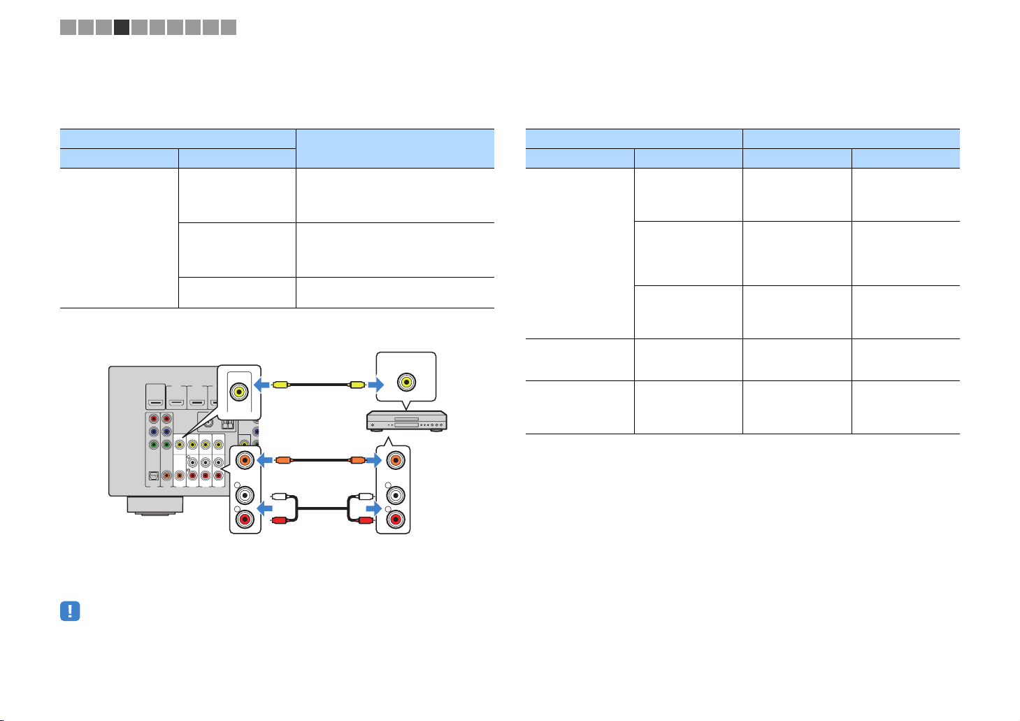
■ Component video connection (RX-V579)
Connect a video device to the unit with a component video cable and an audio cable
(digital optical or digital coaxial). Choose a set of input jacks (on the unit) depending on
the audio output jacks available on your video device.
Output jacks on video device
Video Audio
Digital optical AV 1 (COMPONENT VIDEO + OPTICAL)
Component video
Digital coaxial AV 2 (COMPONENT VIDEO + COAXIAL)
Analog Stereo
AV 1-2 (COMPONENT VIDEO) jacks
The unit (rear)
P
HDMIOUT
HDCP2.2
ARC
P
R
P
B
Y
COMPONENT
VIDEO
OPTICAL
(TV)
AV1
• If you connect a video device to the unit via component video connection, you need to connect your TV to
the MONITOR OUT (COMPONENT VIDEO) jacks of the unit (p.19).
R
HDMI2
HDMI1
(BD/DVD)
P
B
A
FM
Y
75Ω
COMPONENT
VIDEO
VIDEO
COAXIAL
COAXIAL
OPTICAL
AV3
AV2
COAXIAL
( TV )
AV 1
AV 2
AV 1 (OPTICAL) jack or
AV 2 (COAXIAL) jack
R
P
P
B
Y
O
C
(digital optical or digital coaxial)
Input jacks on the unit
You need to change the combination of
video/audio input jacks (p.22).
Video output
(component video)
COMPONENT
VIDEO
PR
R
P
PB
P
B
Y
Y
O
OPTICAL
C
COAXIAL
Video device
Audio output
En 21
1 2 3 4 5 6 7 8 9 10
■ Composite video connection
Connect a video device to the unit with a video pin cable and an audio cable (digital
coaxial or stereo pin cable). Choose a set of input jacks (on the unit) depending on the
audio output jacks available on your video device.
Output jacks on video device
Video Audio
Composite video
HDMIOUT
HDMI1
HDCP2.2
(BD/DVD)
ARC
P
R
P
B
Y
VIDEO
COMPONENT
VIDEO
OPTICAL
COAXIAL
COAXIAL
(TV)
AV4
AV3
AV2
AV1
The unit (rear)
Digital coaxial
Analog stereo
Digital optical
(RX-V579)
AV 3–6 (VIDEO) jacks
(RX-V479)
AV 1–4 (VIDEO) jacks
HDMI2
HDMI4
H
HDMI3
VIDEO
ANTENNA
(RADIO)
COMPONENT
FM
AM
VIDEO
P
R
P
AV6
(RX-V579)
(RX-V479)
VIDEO
COAXIAL
L
R
MONITOROU
B
Y
SUBW
PRE
75Ω
AV5
AV 3 (COAXIAL) jack or
AV 4–6 (AUDIO) jacks
AV 1 (COAXIAL) jack or
AV 2–4 (AUDIO) jacks
V
CC
L
R
Input jacks on the unit
(RX-V579)
AV 3 (VIDEO + COAXIAL)
(RX-V479)
AV 1 (VIDEO + COAXIAL)
(RX-V579)
AV 4–6 (VIDEO + AUDIO)
(RX-V479)
AV 2–4 (VIDEO + AUDIO)
You need to change the combination of
video/audio input jacks (p.22).
Video output
(composite video)
VIDEO
V
Video device
COAXIAL
L
L
R
R
Audio output
(digital coaxial or analog stereo)
■ Changing the combination of video/audio input jacks
If the combination of video/audio input jacks available on the unit does not match your
video device, change its combination according to the output jacks of your device. You
can connect a video device that has the following video/audio output jacks.
Output jacks on video device Input jacks on the unit
Video Audio Video Audio
(RX-V579)
Digital optical HDMI 1–6
HDMI
Digital coaxial HDMI 1–6
Analog stereo HDMI 1–6
Component video
(RX-V579 only)
Analog stereo
Composite video Digital optical
AV 1–2
(COMPONENT
VIDEO)
(RX-V579)
AV 3–6 (VIDEO)
(RX-V479)
AV 1–4 (VIDEO)
AV 1 (OPTICAL)
(RX-V479)
AUDIO 1 (OPTICAL)
(RX-V579)
AV 2–3 (COAXIAL)
(RX-V479)
AUDIO 2 (COAXIAL)
AV 1 (COA XIAL )
(RX-V579)
AV 4–6 (AUDIO)
(RX-V479)
AV 2–4 (AUDIO)
AV 4–6 (AUDIO)
(RX-V579)
AV 1 (OPTICAL)
(RX-V479)
AUDIO 1 (OPTICAL)
• If you connect a video device to the unit via composite video connection, you need to connect your TV to
the MONITOR OUT (VIDEO) jack of the unit (p.20).
En 22
1 2 3 4 5 6 7 8 9 10
❑ Necessary setting
For example, if you have connected a video device to HDMI 2 and AV 6 (AUDIO) jack
(“AV 4” on RX-V479) of the unit, change the combination setting as follows.
HDMI1
(BD/DVD)
VIDEO
COAXIAL
AV4
AV3
MUTE
HDMI 2 jack
HDMI2
HDMI3
HDMI2
ANTENNA
(RADIO)
FM
A
75Ω
AV6
AV5
(RX-V579)
AV 6 (AUDIO) jack
(RX-V479)
AV 4 (AUDIO) jack
OPTION
Cursor keys
DISPLAYRETURN
AV 6
OPTION
Cursor keys
ENTER
HDMI output
HDMI
L
R
HDMI
HDMI
AUDIO
L
L
R
R
Audio output
(analog stereo)
Video device
The unit (rear)
HDMIOUT
HDCP2.2
ARC
P
R
P
B
Y
COMPONENT
VIDEO
OPTICAL
COAXIAL
(TV)
AV2
AV1
After connecting external devices (such as a TV and playback
1
devices) and power cable of the unit, turn on the unit.
Press INPUT to select “HDMI 2” (video input jack to be used) as the
2
input source.
Press OPTION.
3
BLUETOOTH
SETUP
SETU
ENTER
Use the cursor keys (e/r) to select “
5
AV 6
” (“
AV 4
” on
RX-V479
) (audio
input jack to be used).
CHARGE
OUT
ECO
ENHANCER
STEREO
TUNED
SLEEP
MUTE
VOL.
ADAPTIVE DRC
VIRTUAL
Audio••••••AV6
Press OPTION.
6
This completes the necessary settings.
If you select “HDMI 2” as the input source by pressing INPUT, the video/audio played
back on the video device will be output from the unit.
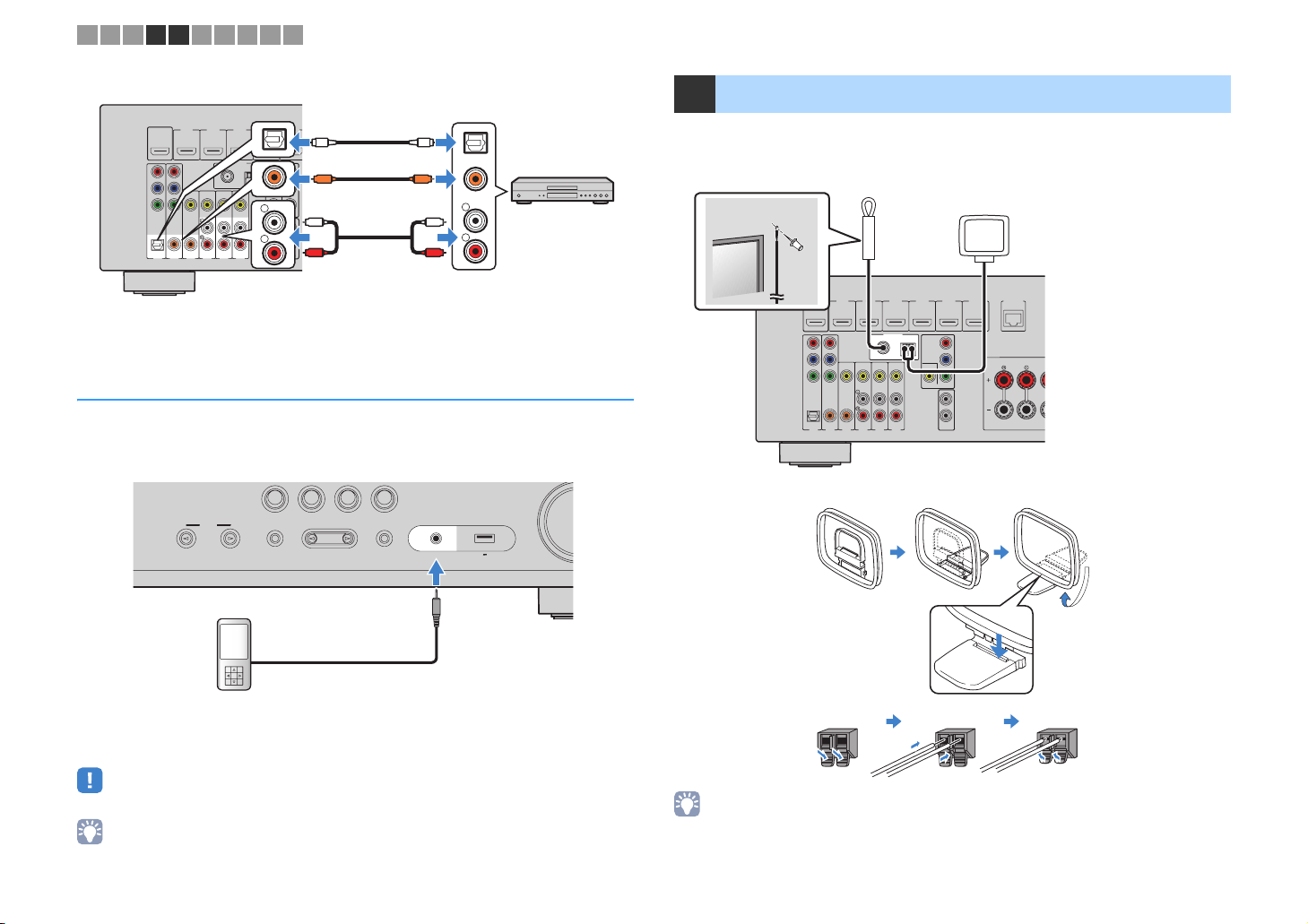
Connecting audio devices (such as CD players)
Connect audio devices such as CD players and MD players to the unit. Depending on
the audio output jacks available on your audio device, choose one of the following
connections.
Audio output jacks on audio device Audio input jacks on the unit
(RX-V579)
Digital optical
Digital coaxial
Analog stereo
AV 1 (OPTICAL)
(RX-V479)
AUDIO 1 (OPTICAL)
(RX-V579)
AV 2–3 (COAXIAL)
(RX-V479)
AUDIO 2 (COAXIAL)
AV 1 (COAXIAL )
(RX-V579)
AV 4–6 (AUDIO)
(RX-V479)
AV 2–4 (AUDIO)
Use the cursor keys (q/w) to select “Audio In” and press ENTER.
4
CHARGE
OUT
ECO
ENHANCER
STEREO
TUNED
SLEEP
MUTE
VOL.
ADAPTIVE DRC
VIRTUAL
Audio In
En 23
1 2 3 4 5 6 7 8 9 10
The unit (rear)
HDMIOUT
P
R
P
B
Y
COMPONENT
VIDEO
OPTICAL
HDMI2
HDMI4
HDMI3
OPTICAL
COMPONENT
AM
VIDEO
P
R
P
B
COAXIAL
VIDEO
L
Y
MONITOROUT
R
SUBWOOFER
PREOUT
AV6
(RX-V579)
AV 1-6 jacks
(RX-V479)
AUDIO 1-2 jacks
AV 1-4 jacks
HDMI5
OO
CC
1
L
2
R
L
R
Audio output
(either digital optical,
digital coaxial, or analog stereo)
OPTICAL
COAXIAL
L
R
Audio device
HDMI1
HDCP2.2
(BD/DVD)
ARC
COAXIAL
(TV)
AV2
AV1
ANTENNA
(RADIO)
FM
75Ω
VIDEO
COAXIAL
AV5
AV4
AV3
Connecting to the jack on the front panel
Use the AUX jack on the front panel to temporarily connect devices such as portable
audio players to the unit.
Before making a connection, stop playback on the device and turn down the volume on the unit.
The unit (front)
BD
DVD
INPUT
TONE CONTROL
NET
TV
PROGRAM
RADIO
STRAIGHT
(CONNECT)
AUX
5V 1A
AUDIO
5 Connecting the FM/AM antennas
Connect the supplied FM/AM antennas to the unit.
Fix the end of the FM antenna to a wall, and place the AM antenna on a flat surface.
FM antenna
AM antenna
N
HDMIOUT
P
R
P
B
Y
COMPONENT
VIDEO
OPTICAL
HDMI2
HDMI1
HDCP2.2
(BD/DVD)
ARC
VIDEO
COAXIAL
COAXIAL
(TV)
AV4
AV3
AV2
AV1
HDMI4
HDMI3
HDMI5
ANTENNA
(RADIO)
COMPONENT
FM
AM
VIDEO
P
R
P
75Ω
AV5
B
VIDEO
Y
MONITOROUT
1
2
SUBWOOFER
PREOUT
AV6
The unit (rear)
Assembling and connecting the AM antenna
ETWORK
HDMI6
HDCP2.2
(NET)
FRONT
Portable audio player
If you select “AUX” as the input source by pressing INPUT, the audio played back on
the device will be output from the unit.
• You need to prepare the audio cable that matches the output jacks on your device.
• For details on how to connect an USB storage device, see “Connecting a USB storage device” (p.59).
Hold down Insert Release
• Unwind only the length of cable needed from the AM antenna unit.
• The wires of the AM antenna have no polarity.
En 24
1 2 3 4 5 6 7 8 9 10
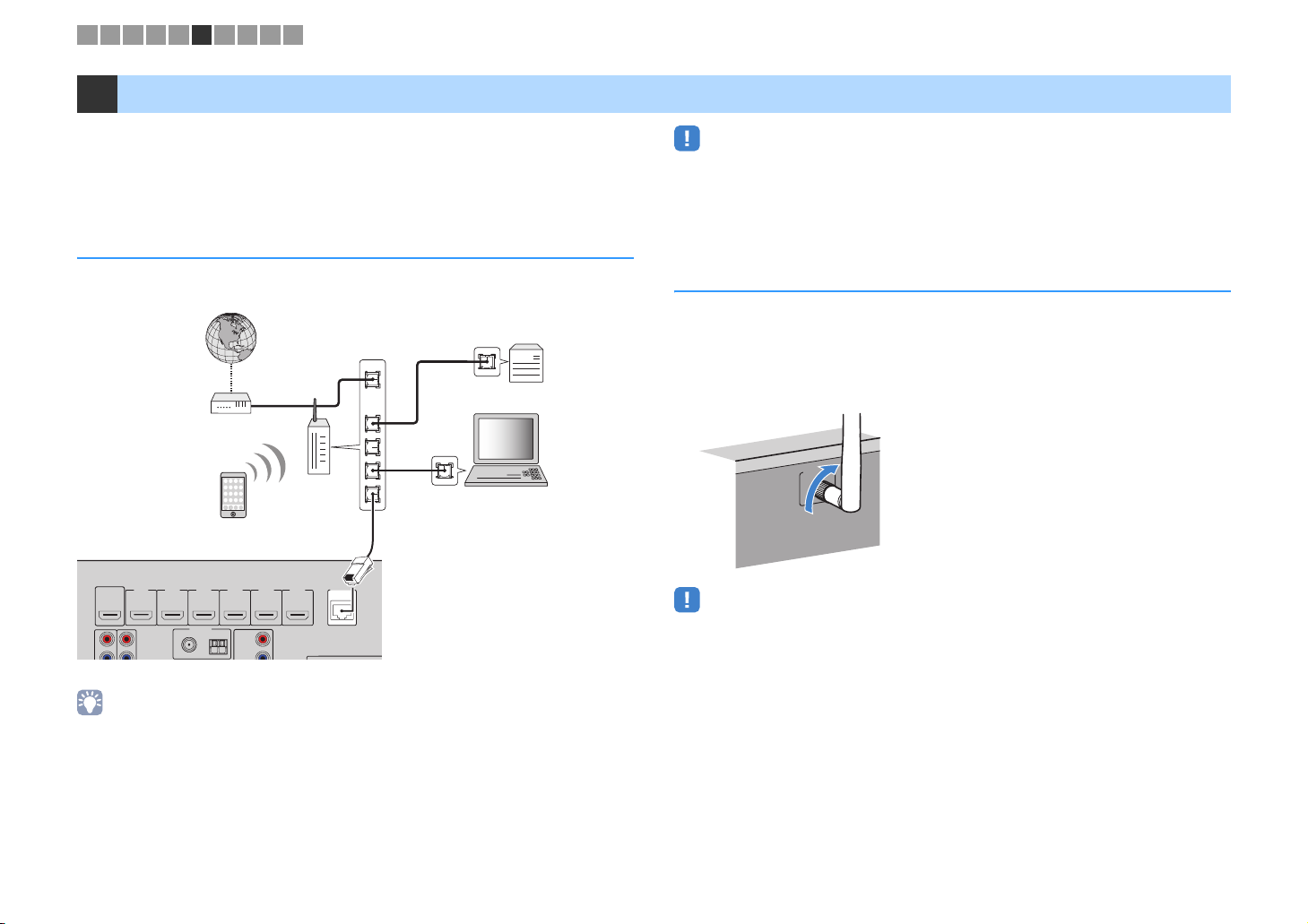
6 Preparing for connecting to a network
Connect the unit to a router (access point) with a network cable, or prepare the wireless
antenna for establishing a wireless network connection.
You can enjoy Internet radio or music files stored on media servers, such as PCs and
Network Attached Storage (NAS), on the unit.
Connecting a network cable
• Some security software installed on your PC or the firewall settings of network devices (such as a router)
may block the access of the unit to the network devices or the Internet. In these cases, configure the
security software or firewall settings appropriately.
• Each server must be connected to the same subnet as the unit.
• To use the service via the Internet, broadband connection is strongly recommended.
Connect the unit to your router with a commercially-available STP network cable (CAT-5
or higher straight cable).
Internet
WAN
LAN
Modem
Wireless
router
Network cable
N
HDMI6
HDCP2.2
ETWORK
(NET)
HDMI
P
HDMIOUT
HDCP2.2
R
75Ω
FM
ANTENNA
(RADIO)
HDMI4
HDMI3
HDMI5
HDMI 1
(
)
OUT
HDMI
BD/DVD
COMPONENT
AM
VIDEO
ARC
P
R
P
B
HDMI1
HDMI2
(BD/DVD)
ARC
The unit (rear)
• If you are using a router that supports DHCP, you do not need to configure any network settings for the
unit, as the network parameters (such as the IP address) will be assigned automatically to it. You only need
to configure the network settings if your router does not support DHCP or if you want to configure the
network parameters manually (p.92).
• You can check whether the network parameters (such as IP address) are properly assigned to the unit in
“Information” (p.92) in the “Setup” menu.
Network Attached Storage
(NAS)
PC
Preparing a wireless antenna
If you connect the unit wirelessly, erect the wireless antenna.
For information on how to connect the unit to a wireless network, see “Connecting to a
network wirelessly” (p.32).
Erect the wireless antenna.
WIRELESS
• Do not apply excessive force on the wireless antenna. Doing so may damage the antenna.
En 25
1 2 3 4 5 6 7 8 9 10
7 Connecting the power cable
Before connecting the power cable (Taiwan and General models only)
Set the switch position of VOLTAGE SELECTOR according to your local voltage.
Voltages are AC 110–120/220–240 V, 50/60 Hz.
• Make sure you set VOLTAGE SELECTOR of the unit BEFORE plugging the power cable into an AC
wall outlet. Improper setting of VOLTAGE SELECTOR may cause damage to the unit and create a
potential fire hazard.
The unit (rear)
WSS
VOLTAGE SELECTOR
SPEAKERS
SURROUNDBACK/BIAMP
SURROUND
/ZONEB
SINGLE
CENTER
After all the connections are complete, plug in the power cable.
The unit (rear)
WSS
VOLTAGESELECTOR
110V
120V
220V
240V
To an AC wall outlet
SPEAKERS
SURROUNDBACK/BIAMP
SURROUND
/ZONEB
SINGLE
CENTER
En 26
1 2 3 4 5 6 7 8 9 10
ZONE A ZONE B
ZONE O
BD
B
DVD
DVD
STRAIGHT
TRAIGH
INPUT
SETUP
TOP MENU
T
RED
RED
TUNING
TUNIN
SLEEP
SLEEP
SCENE
TV
TV
DIRECT
DIREC
PROGRAM
P
FM/AM
FM/A
USB
NET
BLUETOOTH
BLUET
ENTER
HOME
N
MEMORY
MEMOR
PRESET
PRESET
RADIO
NET
NET
ENHANCER BASS
ENHANCE
M
VOLUME
MUTE
MUT
OPTION
DISPLAYRETURN
POP-UP/MENU
POP-UP/MEN
BLU
YELLOWGREEN
YEL
TUNING
TUNIN
ADI
B
BLUE
ME
z z
SETUP
Cursor keys
Cursor keys
ENTER
RETURN
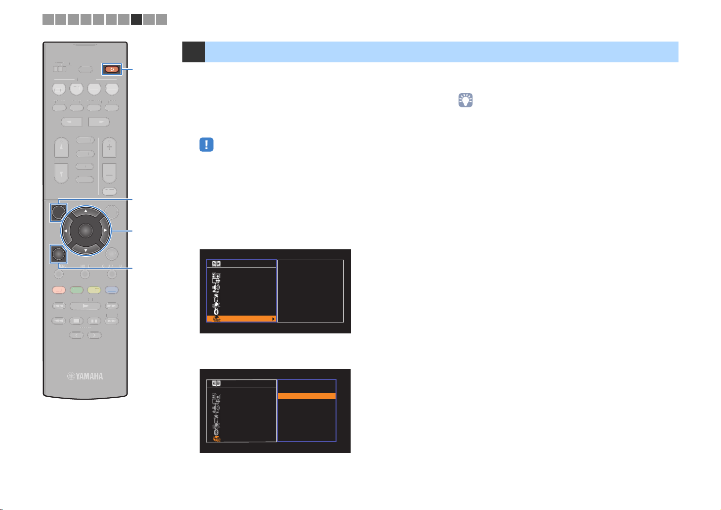
8 Selecting an on-screen menu language
Select the desired on-screen menu language.
Press z (receiver power) to turn on the unit.
1
Turn on the TV and switch the TV input to display
2
video from the unit (HDMI OUT jack).
• Operations with TV screen are available only when your TV is connected to
the unit via HDMI. If not, carry out operations while viewing the front display.
• If you turn on the unit for the first time, the message regarding the network
setup appears. To continue the language setup, press RETURN.
Press SETUP.
3
Use the cursor keys to select “Language” and press
4
ENTER.
Setup
Speaker
HDMI
Sound
ECO
Function
Network
Bluetooth
Language
English
日本語
Français
Deutsch
Español
Русский
Italiano
中文
To exit from the menu, press SETUP.
6
• The information on the front display is provided in English only.
Use the cursor keys to select the desired language.
5
Setup
Speaker
HDMI
Sound
ECO
Function
Network
Bluetooth
Language
English
日本語
Français
Deutsch
Español
Русский
Italiano
中文
En 27
1 2 3 4 5 6 7 8 9 10
ZONE A ZONE B
ZONE O
BD
B
DVD
DVD
STRAIGHT
INPUT
SETUP
SETU
RETUR
TOP MENU
T
RED
RED
TUNING
TUNIN
SLEEP
SLEEP
SCENE
TV
TV
DIRECT
DIREC
PROGRAM
P
FM/AM
FM/A
USB
NET
BLUETOOTH
BLUET
ENTER
ENTE
HOME
N
MEMORY
MEMOR
PRESET
PRESET
RADIO
NET
NET
ENHANCER BASS
ENHANCE
VOLUME
MUTE
MUT
OPTION
DISPLAYRETURN
POP-UP/MENU
POP-UP/MEN
BLUE
BLU
YELLOWGREEN
YEL
TUNING
TUNIN
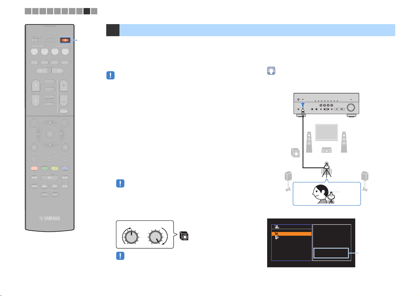
9 Optimizing the speaker settings automatically (YPAO)
z z
ADI
B
ME
The Yamaha Parametric room Acoustic Optimizer (YPAO) function
detects speaker connections, measures the distances from them to
your listening position(s), and then automatically optimizes the
speaker settings, such as volume balance and acoustic
parameters, to suit your room.
• When you use the front 5.1-channel speaker (Virtual CINEMA FRONT)
configuration (p.13), set “Virtual CINEMA FRONT” (p.82) in the “Setup” menu to
“On” beforehand.
• Please note the following when using YPAO.
– Use YPAO after connecting a TV and speakers to the unit.
– During the measuring process, test tones are output at high volume. Ensure that
the test tones do not frighten small children.
– During the measuring process, you cannot adjust the volume.
– During the measuring process, keep the room as quiet as possible.
– Do not connect headphones.
– Do not stand between the speakers and the YPAO microphone during the
measurement process (about 3 minutes).
Press z (receiver power) to turn on the unit.
1
Turn on the TV and switch the TV input to display
2
video from the unit (HDMI OUT jack).
• Operations with TV screen are available only when your TV is connected to
the unit via HDMI. If not, carry out operations while viewing the front display.
Place the YPAO microphone at your listening
4
position and connect it to the YPAO MIC jack on the
front panel.
• Place the YPAO microphone at your listening position (same height as your
ears). We recommend the use of a tripod as a microphone stand. You can
use the tripod screws to stabilize the microphone.
The unit (front)
12
9
45
3
Ear height
Turn on the subwoofer and set the volume to half. If the
3
crossover frequency is adjustable, set it to maximum.
VOLUME HIGH CUT
• (RX-V579 only)
If you are using bi-amp connection or
(p.80) in the “
CROSSOVER/
9
MIN MAXMIN MAX
Zone B
Setup
” menu to the appropriate setting before starting
speakers, set “Power AMP Assign”
YPAO
.
The following screen appears on the TV.
Auto Setup
Start
Exit
Press SETUP key to
Start
Power Amp Assign
Basic
“
Power AMP Assign
setting (p.80)
(RX-V579 only)
”
En 28
1 2 3 4 5 6 7 8 9 10
ZONE A ZONE B
ZONE O
BD
DVD
STRAIGHT
INPUT
SETUP
TOP MENU
T
RED
TUNING
TUNIN
SLEEP
LEEP
SCENE
TV
DIRECT
DIRECT
PROGRAM
GR
FM/AM
USB
NET
NE
BLUETOOTH
BLUET
ENTER
HOME
MEMORY
MEM
PRESET
PRESET
RADIO
NET
ENHANCER BASS
ENHANCE
VOLUME
MUTE
MUT
OPTION
DISPLAYRETURN
POP-UP/MENU
POP-UP/MEN
BLUE
YELLOWGREEN
TUNING
ADI
UNIN
ME
SETUP
Cursor keys
Cursor keys
ENTER
RETURN
To start the measurement, use the cursor keys to
5
select “Start” and press SETUP.
The measurement will start in 10 seconds. Press ENTER to
start the measurement immediately.
• To stop the measurement temporarily, press RETURN and follow the
procedure in “Error messages” (p.30).
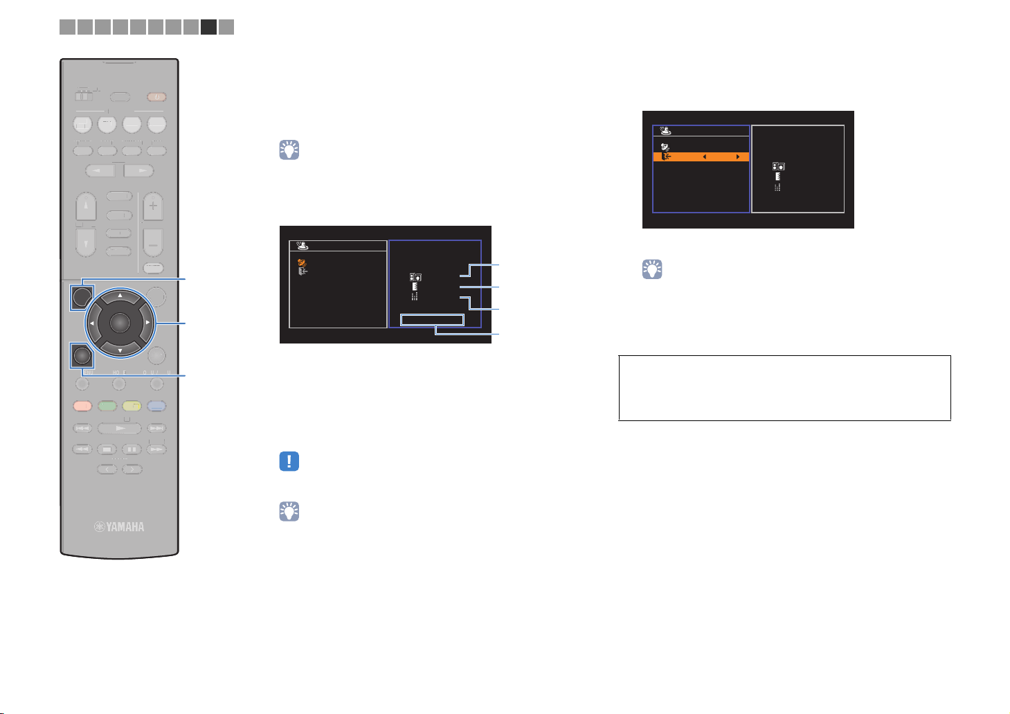
The following screen appears on the TV when the
measurement finishes.
Auto Setup
Start
Exit
Measurement
Finished
Result
3 / 2 / 0.1 ch
3.0 / 10.5 m
-3.0 / +10.0 dB
OK:ENTER
1
2
3
4
1 The number of speakers (front side/rear
side/subwoofer)
2 Speaker distance (nearest/farthest)
3 Adjustment range of speaker output level
4 Warning message (if available)
• If any error message (such as E-1) or warning message (such as W-1)
appears, see “Error messages” (p.30) or “Warning messages” (p.31).
Use the cursor keys (e/r) to select “SAVE” and
6
press ENTER.
Auto Setup
Start
Exit
SAVE
Measurement
Finished
Result
3 / 2 / 0.1 ch
3.0 / 10.5 m
-3.0 / +10.0 dB
The adjusted speaker settings are applied.
• To finish the measurement without saving the result, select “CANCEL”.
Disconnect the YPAO microphone from the unit.
7
This completes optimization of the speaker settings.
Caution
• The YPAO microphone is sensitive to heat, so should not be placed anywhere
where it could be exposed to direct sunlight or high temperatures (such as on
top of AV equipment).
• A speaker with a problem is indicated by blinking of the speaker indicators in
the front display.
• If multiple warnings are given (when operating with the front display), use
the cursor keys (q/w) to check the other warning messages.
En 29
1 2 3 4 5 6 7 8 9 10
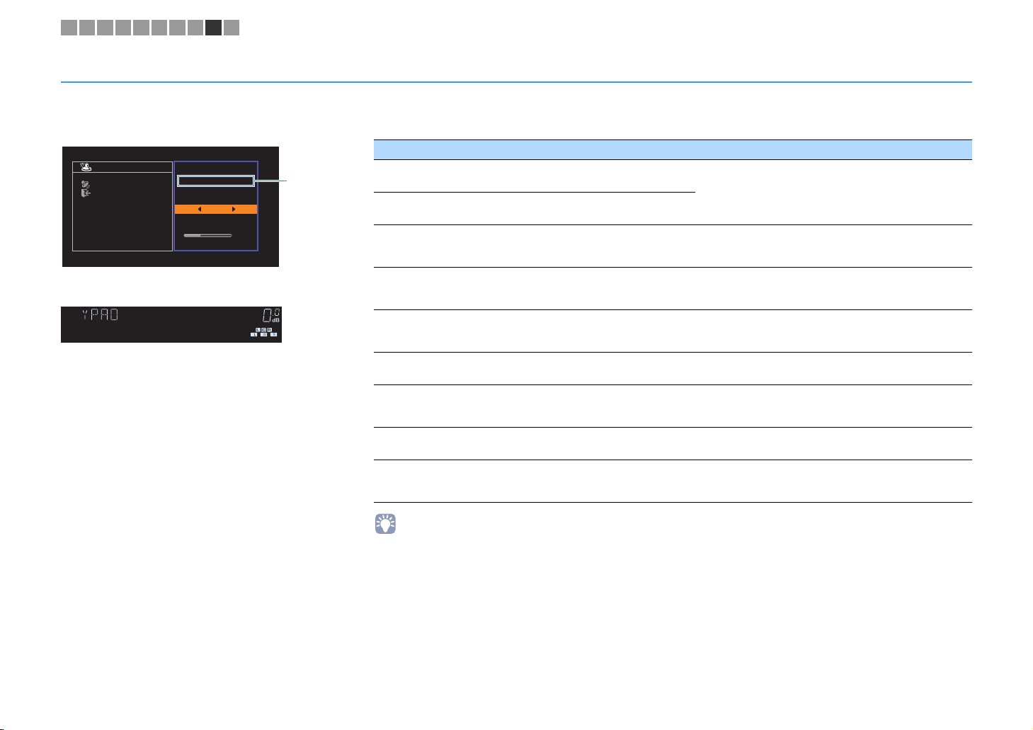
Error messages
If any error message is displayed during the measurement, resolve the problem and perform YPAO again.
Error message Cause Remedy
Auto Setup
Start
Exit
ERROR
E-5:Noisy
PROCEED
5%
TV screen
CHARGE
OUT
ECO
ENHANCER
STEREO
TUNED
SLEEP
MUTE
VOL.
ADAPTIVE DRC
VIRTUAL
E-5:NOISY
Front display
■ Procedure to handle errors
Check the content of error message and
1
press ENTER.
Use the cursor keys (e/r) to select the
2
desired operation.
To exit the YPAO measurement:
a Select “EXIT” and press ENTER.
b Use the cursor keys (q/w) to select “Exit” and press
ENTER.
c Disconnect the YPAO microphone from the unit.
To retry the
beginning:
Select “RETRY” and press ENTER.
To proceed with the current YPAO
measurement (for E-5 and E-9 only):
Select “PROCEED” and press ENTER.
YPAO
measurement from
Error
message
E-1:No Front SP
(E-1:NO FRNT SP)
E-2:No Sur. SP
(E-2:NO SUR SP)
E-4:SBR → SBL
(E-4:SBR → SBL)
E-5:Noisy
(E-5:NOISY)
E-6:Check Sur.
(E-6:CHECK SUR)
E-7:No MIC
(E-7:NO MIC)
E-8:No Signal
(E-8:NO SIGNAL)
E-9:User Cancel
(E-9:CANCEL)
E-10:Internal Err.
(E-10:INTERNAL)
• Texts in parentheses denote indicators on the front display.
Front speakers are not detected.
One of the surround speakers cannot be
detected.
A surround back speaker is connected to
the R side only.
The noise is too loud.
Surround back speakers are connected,
but no surround speakers are connected.
The YPAO microphone has been removed.
The YPAO microphone cannot detect test
tones.
The measurement has been canceled. Retry or exit YPAO as necessary.
An internal error has occurred.
Exit YPAO, turn off the unit, and then check the speaker
connections.
When using only one surround back speaker, you need to
connect it to the SINGLE jack (L side). Exit YPAO, turn off the
unit, and then reconnect the speaker.
Keep the room quiet and retry YPAO. If you select
“PROCEED”, YPAO takes the measurement again and
ignores any noise detected.
Surround speakers need to be connected in order to use
surround back speakers. Exit YPAO, turn off the unit, and
then reconnect the speakers.
Connect the YPAO microphone to the YPAO MIC jack firmly
and retry YPAO.
Connect the YPAO microphone to the YPAO MIC jack firmly
and retry YPAO. If this error occurs repeatedly, contact the
nearest authorized Yamaha dealer or service center.
Exit YPAO, and turn off and on the unit. If this error occurs
repeatedly, contact the nearest authorized Yamaha dealer or
service center.
En 30
Loading…
Скачать
AV Receiver
Owner’s Manual
Read the supplied booklet
“
Safety Brochure
”
before using the unit.
English
00_RX-V479_V579_om_U.book Page 1 Wednesday, March 25, 2015 9:59 AM
Report abuse
Libble takes abuse of its services very seriously. We’re committed to dealing with such abuse according to the laws in your country of residence. When you submit a report, we’ll investigate it and take the appropriate action. We’ll get back to you only if we require additional details or have more information to share.
Product:
Get your user manual by e-mail
Enter your email address to receive the manual of Yamaha RX-V579 in the language / languages: English as an attachment in your email.
The manual is 19,21 mb in size.
You will receive the manual in your email within minutes. If you have not received an email, then probably have entered the wrong email address or your mailbox is too full. In addition, it may be that your ISP may have a maximum size for emails to receive.
The manual is sent by email. Check your email
If you have not received an email with the manual within fifteen minutes, it may be that you have a entered a wrong email address or that your ISP has set a maximum size to receive email that is smaller than the size of the manual.