

YSP-3000
E
Digital Sound Projector
TM
Système Acoustique Numérique
OWNER’S MANUAL
MODE D’EMPLOI
MANUALE DI ISTRUZIONI
MANUAL DE INSTRUCCIONES

CAUTION: READ THIS BEFORE OPERATING THIS UNIT.
Caution: Read this before operating this unit.
To assure the finest performance, please read this manual
1
carefully. Keep it in a safe place for future reference.
2 Install this sound system in a well ventilated, cool, dry, clean
place with at least 5 cm (2 in) of space above (or below) this unit
– away from direct sunlight, heat sources, vibration, dust,
moisture, and/or cold.
3 Locate this unit away from other electrical appliances, motors, or
transformers to avoid humming sounds.
4 Do not expose this unit to sudden temperature changes from cold
to hot, and do not locate this unit in an environment with high
humidity (i.e. a room with a humidifier) to prevent condensation
inside this unit, which may cause an electrical shock, fire,
damage to this unit, and/or personal injury.
5 Avoid installing this unit where foreign object may fall onto this
unit and/or this unit may be exposed to liquid dripping or
splashing. On the top of this unit, do not place:
– Other components, as they may cause damage and/or
discoloration on the surface of this unit.
– Burning objects (i.e. candles), as they may cause fire, damage
to this unit, and/or personal injury.
– Containers with liquid in them, as they may fall and liquid
may cause electrical shock to the user and/or damage to this
unit.
6 Do not cover this unit with a newspaper, tablecloth, curtain, etc.
in order not to obstruct heat radiation. If the temperature inside
this unit rises, it may cause fire, damage to this unit, and/or
personal injury.
7 Do not plug in this unit to a wall outlet until all connections are
complete.
8 Do not operate this unit upside-down. It may overheat, possibly
causing damage.
9 Do not use force on switches, knobs and/or cords.
10 When disconnecting the power supply cable from the wall outlet,
grasp the plug; do not pull the cable.
11 Do not clean this unit with chemical solvents; this might damage
the finish. Use a clean, dry cloth.
12 Only voltage specified on this unit must be used. Using this unit
with a higher voltage than specified is dangerous and may cause
fire, damage to this unit, and/or personal injury. Yamaha will not
be held responsible for any damage resulting from use of this unit
with a voltage other than specified.
13 To prevent damage by lightning, keep the power supply cable
disconnected from a wall outlet or this unit during a lightning
storm.
14 Do not attempt to modify or fix this unit. Contact qualified
Yamaha service personnel when any service is needed.
The cabinet should never be opened for any reasons.
15 When not planning to use this unit for long periods of time (i.e.
vacation), disconnect the power supply cable from the wall
outlet.
16 Be sure to read the “Troubleshooting” section on common
operating errors before concluding that this unit is faulty.
17 Before moving this unit, press STANDBY/ON to set this unit in
standby mode, and disconnect the power supply cable from the
wall outlet.
18 Condensation will form when the surrounding temperature
changes suddenly. Disconnect the power supply cable from the
outlet, then leave the unit alone.
19 When using the unit for a long time, the unit may become warm.
Turn the power off, then leave the unit alone for cooling.
20 Install this unit near the AC outlet and where the AC power plug
can be reached easily.
21 The batteries shall not be exposed to excessive heat such as
sunshine, fire or the like.
WAR NING
TO REDUCE THE RISK OF FIRE OR ELECTRIC SHOCK, DO
NOT EXPOSE THIS UNIT TO RAIN OR MOISTURE.
WAR NING
THE POWER SUPPLY CABLE OF THIS UNIT MUST BE
CONNECTED TO THE MAIN SOCKET OUTLET VIA A
PROTECTIVE EARTHING CONNECTION.
2
This unit is not disconnected from the AC power source as long as
it is connected to the AC wall outlet, even if this unit itself is
turned off by STANDBY/ON. This state is called the standby
mode. In this state, this unit is designed to consume a very small
quantity of power.
FOR U.K. CUSTOMERS
If the socket outlets in the home are not suitable for the plug
supplied with this appliance, it should be cut off and an
appropriate 3 pin plug fitted. For details, refer to the instructions
described below. Note that the plug severed from the mains lead
must be destroyed, as a plug with bared flexible cord is hazardous
if engaged in a live socket outlet.
IMPORTANT
THE WIRES IN MAINS LEAD ARE COLOURED IN
ACCORDANCE WITH THE FOLLOWING CODE:
Blue: NEUTRAL
Brown: LIVE
As the colours of the wires in the mains lead of this apparatus may
not correspond with the coloured markings identifying the
terminals in your plug, proceed as follows:
The wire which is coloured BLUE must be connected to the
terminal which is marked with the letter N or coloured BLACK.
The wire which is coloured BROWN must be connected to the
terminal which is marked with the letter L or coloured RED. Make
sure that neither core is connected to the earth terminal of the three
pin plug.
CAUTION
Danger of explosion if battery is incorrectly replaced. Replace
only with the same or equivalent type.
CAUTION
Use of controls or adjustments or performance of procedures other
than those specified herein may result in hazardous radiation
exposure.
This symbol mark is according to the
EU directive 2002/96/EC.
This symbol mark means that electrical
and electronic equipment, at their endof-life, should be disposed of separately
from your household waste.
Please act according to your local rules
and do not dispose of your old products
with your normal household waste.
i En

Contents
INTRODUCTION
Overview ……………………………………………………….. 2
Features ………………………………………………………… 3
Using this manual ………………………………………….. 5
Supplied accessories ……………………………………….6
Controls and functions …………………………………… 7
Front panel ………………………………………………………. 7
Front panel display …………………………………………… 8
Rear panel ……………………………………………………….. 9
Remote control (Europe, Australia, Asia,
and Korea models) ………………………………………. 10
Remote control (U.S.A. and Canada models) ……… 13
PREPARATION
Installation …………………………………………………… 16
Before installing this unit …………………………………. 16
Installing this unit …………………………………………… 16
Connections …………………………………………………. 19
Before connecting components …………………………. 20
Connections using HDMI cables ………………………. 21
Connecting a TV …………………………………………….. 22
Connecting a DVD player/recorder …………………… 23
Connecting a digital satellite tuner
or a cable TV tuner ……………………………………… 24
Connecting a digital airwave tuner ……………………. 25
Connecting a portable audio player …………………… 26
Connecting other external components ……………… 27
Connecting a subwoofer ………………………………….. 28
Connecting the FM antenna ……………………………… 29
About the IR IN terminal (U.S.A. and
Canada models only) …………………………………… 29
Connecting the AC power supply cable …………….. 29
SETUP
Getting started …………………………………………….. 30
Installing batteries in the remote control ……………. 30
Operation range of the remote control ……………….. 30
Turning on this unit or
setting it to the standby mode ……………………….. 31
Using SET MENU ………………………………………… 32
Displaying the OSD (on-screen display) ……………. 32
The flow chart of SET MENU ………………………….. 33
Changing OSD language ………………………………. 34
AUTO SETUP (IntelliBeam) ………………………… 35
The flow chart of AUTO SETUP ……………………… 35
Installing the IntelliBeam microphone ………………. 36
Using AUTO SETUP (IntelliBeam) ………………….. 37
Using the system memory …………………………….. 42
Convenient usage of the system memory …………… 42
Saving settings ……………………………………………….. 42
Loading settings ……………………………………………… 43
Manual tuning ………………………………………………… 49
Automatic preset tuning …………………………………… 50
Manual preset tuning ………………………………………. 51
Selecting a preset station …………………………………. 52
Displaying the Radio Data System information
(Europe model only) ……………………………………. 52
Enjoying surround sound ………………………………54
5 Beam ………………………………………………………….. 54
Stereo plus 3 Beam …………………………………………. 55
3 Beam ………………………………………………………….. 55
My Surround ………………………………………………….. 55
Enjoying 2-channel sources in surround sound …… 57
Enjoying TV in surround sound ……………………….. 58
Adjusting surround mode parameters ………………… 59
Enjoying stereo sound ……………………………………60
2-channel stereo playback ………………………………… 60
5-channel stereo playback ………………………………… 60
Playing back sound clearly (My Beam) …………..61
Using auto-adjust function ……………………………….. 61
Using manual-adjust function …………………………… 62
Using sound field programs ……………………………63
CINEMA DSP programs …………………………………. 64
Using the music enhancer ………………………………66
Using the volume mode
(Night listening enhancer/TV volume equal mode)
Using the sleep timer ……………………………………..68
Displaying the input source information …………70
Using the HDMI control feature …………………….71
ADVANCED OPERATION
MANUAL SETUP …………………………………………72
Using MANUAL SETUP ………………………………… 73
BEAM MENU ……………………………………………….. 74
SOUND MENU ……………………………………………… 78
INPUT MENU ……………………………………………….. 80
DISPLAY MENU …………………………………………… 83
Adjusting the audio balance …………………………..84
Using the test tone ………………………………………….. 84
Using the audio output being played back ………….. 85
Selecting the input mode ………………………………..87
Adjusting the system parameters …………………..88
Using the system parameters ……………………………. 88
Setting the MEMORY PROTECT ……………………. 89
Setting the MAX VOLUME …………………………….. 90
Setting the TURN ON VOLUME …………………….. 90
Setting the DEMO MODE ………………………………. 91
Setting the PANEL INPUT KEY ……………………… 92
Disabling the front panel keys ………………………….. 93
Setting the FACTORY PRESET ………………………. 94
Remote control features …………………………………96
Setting remote control codes ……………………………. 96
Controlling other components ………………………….. 97
Using the TV macro ……………………………………… 100
67
PREPARATIONINTRODUCTION
SETUP
OPERATION
BASIC
OPERATION
ADVANCED
INFORMATION
ADDITIONAL
BASIC OPERATION
Playback ……………………………………………………… 45
Selecting the input source ………………………………… 45
Playing back sources ……………………………………….. 46
Adjusting the volume ………………………………………. 47
FM tuning ……………………………………………………. 48
FM controls and functions ……………………………….. 48
Automatic tuning ……………………………………………. 49
ADDITIONAL INFORMATION
Troubleshooting …………………………………………..102
Glossary ………………………………………………………105
Index …………………………………………………………..107
Specifications ………………………………………………108
List of remote control codes …………………………………….i
1 En
English
Overview
Overview
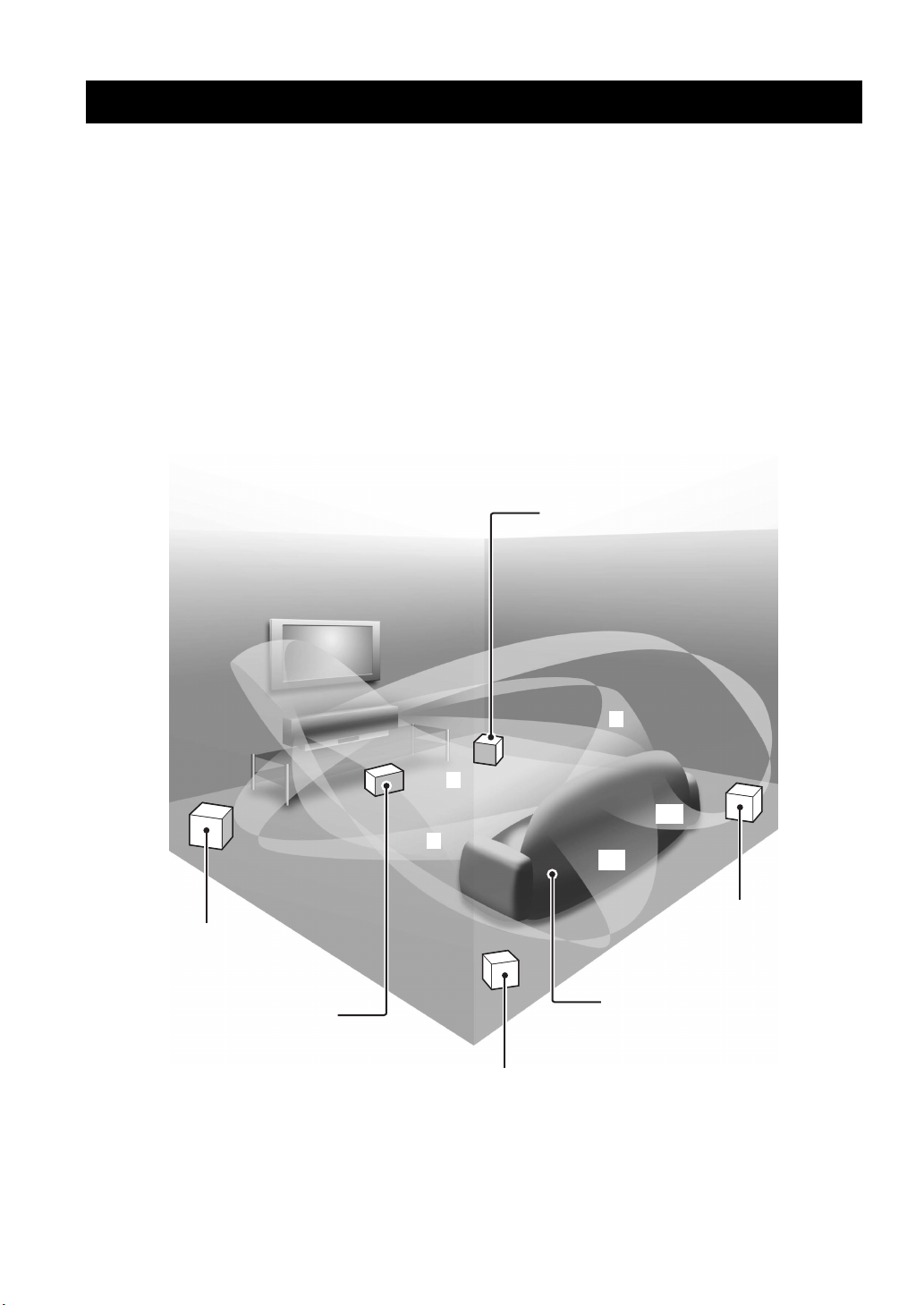
It is generally accepted that in order to fully enjoy the benefits of surround sound at home, you must endure the agony of
wiring and installing a great number of speakers in the hope that your listening room will give you the same kind of
surround sound experience as your local movie theater.
Yamaha YSP-3000 Digital Sound Projector challenges this preconception that complicated speaker setup and
troublesome wiring go hand-in-hand with the enjoyment of multi-channel surround sound.
This slimline unit does away with the need for complicated wiring and installation worries, leaving you with a unit that is
not only easy to set up, but is also capable of reproducing the kind of powerful surround sound you have been waiting for
from its built-in 2 woofers and 21 full-range small speakers.
You can fine-tune the parameters of this unit to adjust the delay time for separate sound beams, resulting in highly
directional sound that comes in on the listening position from all directions.
The YSP-3000 projects sound beams containing surround sound information for the front right (R), front left (L),
surround right (SR), and surround left (SL) speaker positions, which are reflected off the walls of your listening room
before reaching the actual listening position. With the addition of center (C) sound beams, this Digital Sound Projector
creates true-to-life 5.1-channel surround sound that makes you feel as if there are actual speakers around the room.
Sit back and enjoy the real sound experience of this simple, yet stylish Digital Sound Projector.
Imaginary
front right
speaker
Imaginary
front left
speaker
Imaginary
center
speaker
R
C
SR
L
SL
Imaginary
surround right
speaker
Listening position
Imaginary
surround left
speaker
2 En

Features
Features
Digital Sound Projector™
The Digital Sound Projector technology allows one slim
unit to control and steer multiple channels of sound to
generate multi-channel surround sound, thus eliminates
the need for satellite loudspeakers and cabling normally
associated with conventional surround sound systems.
This unit also employs the beam modes that let you enjoy
the surround sound (5 Beam, Stereo plus 3 Beam, 3 Beam,
and My Surround), 2-channel and 5-channel stereo
playback, and My Beam.
My Surround
In addition to the above mentioned beam modes, this unit
is equipped with My Surround beam mode that allows you
to enjoy surround system even in a small listening area.
My Beam
This unit employs My Beam that ensures a clear sound in
a noisy environment. You can adjust the beam angle
manually or automatically using the supplied remote
control to the maximum of 45°, rightward and leftward.
Cinema DSP
This unit employs the Cinema DSP technology developed
by Yamaha Electronics Corp. that lets you experience
movies at home with all the original dramatic sound
impact.
HDMI™ (High-Definition Multimedia Interface)
◆ HDMI interface for standard, enhanced, or high-definition
video (including 1080p video signal transmission) as well as
multi-channel digital audio based on HDCP
◆ Simple and easy connections with HDMI supported external
components
◆ Functional link with an HDMI control-compatible TV
Versatile Remote Control
The supplied remote control comes with preset remote
control codes used to control the DVD player, VCR, cable
TV tuner, and digital satellite tuner connected to this unit.
In addition, the remote control is equipped with the macro
capability that enables a series of operations with the press
of a single button.
AUTO SETUP (IntelliBeam)
This unit employs the automatic sound beam and acoustic
optimization technology with the aid of the supplied
IntelliBeam microphone. You can avoid troublesome
listening-based speaker setup and achieve highly accurate
sound beam adjustments that best match your listening
environment.
Compatibility with the Newest Technologies
This unit employs decoders compatible with Dolby
Digital, DTS, Dolby Pro Logic, Dolby Pro Logic II, DTS
Neo:6, Music Enhancer, and Neural Surround.
◆ Dolby Digital
This is the standard audio signal format used on various
digital media such as DVD, Blu-Ray, and HD DVD. This
surround technology delivers high-quality digital audio for up
to 5.1 discrete channels to produce a directional and more
realistic effect.
◆ DTS
This is the standard audio signal format used on various
digital media such as DVD, Blu-Ray, and HD DVD. This
surround technology delivers high-quality digital audio for up
to 5.1 discrete channels to produce a directional and more
realistic effect.
◆ Dolby Pro Logic
This sophisticated, matrix decoding technology up-converts
any 2-channel source audio to a 5.1-channel full bandwidth
playback, resulting in a surround sound experience.
◆ Dolby Pro Logic II
This is a redesigned version of Dolby Pro Logic that employs
2 stereo surround channels, a subwoofer, and a greatly
enhanced steering logic. This improved technology provides
an exceptionally stable sound field that simulates 5.1 to a
much greater degree than the original Dolby Pro Logic.
◆ DTS Neo:6
This technology decodes the conventional 2-channel sources
for 6-channel playback, enabling playback with the full-range
channels with higher separation. Music mode and Cinema
mode are available to play back music and movie sources
respectively.
◆ Music Enhancer to restore the original depth and width of
compression artifacts such as the MP3 format.
◆ Neural Surround decoder (U.S.A and Canada models only)
Sophisticated FM tuner
◆ 40-station random and direct preset tuning
◆ Automatic preset tuning
◆ Radio Data System capability (Europe model only)
XM™ Satellite Radio
(U.S.A. and Canada models only)
◆ XM Satellite Radio tuning capability (using the XM MiniTuner Dock, and Antenna sold separately by XM Satellite
Radio)
◆ Neural Surround decoder to play back the XM HD content of
XM Satellite Radio broadcasts in multi-channels, resulting in
a full surround sound experience
◆ XM Satellite Radio information displaying capability
iPod™ Controlling Capability
(U.S.A., Canada, and Australia models only)
◆ DOCK terminal to connect a Yamaha iPod universal dock
(such as the YDS-10, sold separately), which supports iPod
(Click and Wheel), iPod nano, and iPod mini
◆ Playback information displaying capability
◆ Battery charging capability
INTRODUCTION
English
3 En

Features
The “ ” logo and “IntelliBeam” are trademarks of
YAMAHA Corporation.
The “ ” logo and “Cinema DSP” are registered
trademarks of YAMAHA Corporation.
Manufactured under license from Dolby Laboratories.
“Dolby”, “Pro Logic”, and the double-D symbol are trademarks
of Dolby Laboratories.
“DTS” and “Neo:6” are registered trademarks of DTS, Inc.
“HDMI”, the “HDMI” logo and “High-Definition Multimedia
Interface” are trademarks or registered trademarks of HDMI
Licensing LLC.
Manufactured under license from 1 Ltd. Worldwide patents
applied for.
The “ ” logo and “Digital Sound Projector
™
” are trademarks
of 1 Ltd.
TruBass, SRS and the “ ” symbol are registered trademarks
of SRS Labs, Inc. TruBass technology is incorporated under
license from SRS Labs, Inc.
™
is a trademark of DiMAGIC Co., Ltd.
4 En

Using this manual
Using this manual
Notes
• This manual describes how to connect and operate this unit. For details regarding the operation of external components, refer to the
supplied owner’s manual for each component.
• Operations in this manual use keys on the supplied remote control of this unit unless otherwise specified.
• y indicates a tip for your operation.
• This manual is printed prior to production. Designs and specifications are subject to change in part as a result of improvements, etc. In
case of differences between the manual and the product, the product has priority.
1 Install this unit in your listening room.
See “Installation” on page 16.
2 Connect this unit to your TV and other external components.
See “Connections” on page 19.
3 Prepare the remote control and turn on the power of this unit.
See “Getting started” on page 30.
INTRODUCTION
4 Run AUTO SETUP.
See “AUTO SETUP (IntelliBeam)” on page 35.
5 Play back a source.
See “Playback” on page 45.
6 Change the beam modes and/or CINEMA DSP settings.
See “Enjoying surround sound” on page 54.
If you want to make additional settings
and adjustments
7 Run MANUAL SETUP to fine-tune settings and/or set remote control codes.
See “MANUAL SETUP” on page 72 and “Remote control features” on page 96.
English
5 En
Supplied accessories
Supplied accessories
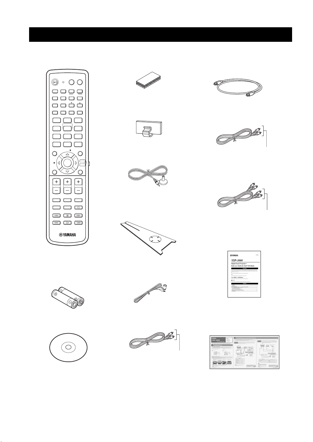
Check that you have received all of the following parts.
Remote control (×1)
POWERPOWERSTANDBY/ON
AV
TV
AUX1 AUX2
INPUT1
TV
PRESET/TUNE
CATFM/XM
AUTO
SETUP
INPUTMODE
MY BEAM
5
+10
ENTRY
ENTER
CH
TV INPUT TV MUTE
DOCK
AUX3
TV
MACRO
MEMORYSEARCH
SLEEP
321
6
SPORTS
9
SUR. DECODE
RETURNDISPLAY
TV VOL
CODE SET
TV/AV
YSP
DVD
STB
VOL MODE
5BEAM ST+3BEAM 3BEAM
STEREO MY SUR.
4
MUSIC MOVIE
78
OFF
0
ENHANCER MENU
CAT/
A-E
VOLUME
MUTE
CH LEVEL TEST
(U.S.A. and Canada models)
Fasteners (×4)
Cable clamp (×1)
IntelliBeam microphone
(×1)
Cardboard microphone
stand (×1)
Optical cable (×1)
Digital audio pin cable (×1)
(Orange)
Audio pin cable (×1)
(White/Red)
REFERENCE GUIDE
(iPod/XM Radio) (×1)
Demonstration DVD
6 En
Batteries (×2)
(AA, R6, UM-3)
(×1)
Indoor FM antenna (×1)
OSD* video pin cable (×1)
(Yellow)
*OSD: On-Screen Display
(U.S.A., Canada, and Australia
models only)
QUICK REFERENCE
GUIDE
* The number of provided languages
varies depending on the model.
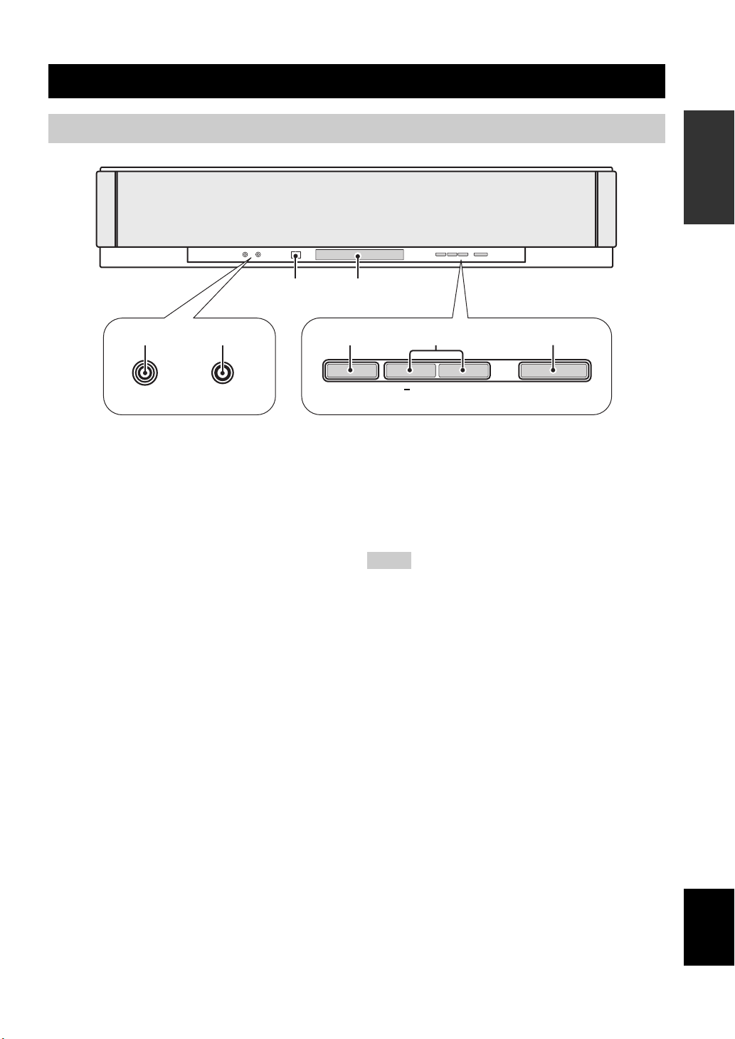
Front panel
Controls and functions
Controls and functions
INTRODUCTION
3 4
21
AUX 3
INTELLIBEAM MIC
1 AUX 3 input jack
Connect your portable audio player (see page 26).
2 INTELLIBEAM MIC jack
Connect the supplied IntelliBeam microphone for AUTO
SETUP (see page 36).
3 Remote control sensor
Receives infrared signals from the remote control.
4 Front panel display
Shows information about the operational status of this
unit.
5 INPUT
Press repeatedly to switch between input sources (see
page 45).
Outputs a test tone to experience the sound beam (see
page 91).
5
INPUT
6
VOLUME
+
7
STANDBY/ON
6 VOLUME +/–
Controls the volume level of all audio channels (see
page 47).
7 STANDBY/ON
Turns on the power of this unit or sets it to the standby
mode (see page 31).
Notes
• When you turn on this unit, you will hear a click sound
followed by the 4 to 5-second interval before sound
reproducing.
• In the standby mode, this unit consumes a small amount of
power in order to receive infrared signals from the remote
control or to search for HDMI signals.
7 En
English
Controls and functions
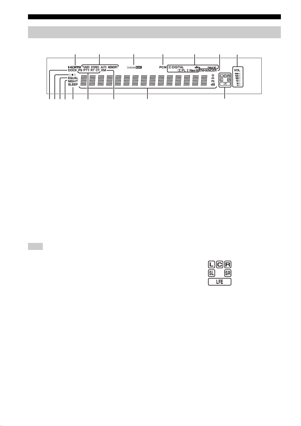
Front panel display
1
0
89
AB C D
1 HDMI indicator
Lights up when the signal of the selected input source is
input at the HDMI IN jack(s).
2 TUNER indicators
FM: Light up when this unit is receiving an FM broadcast.
XM: MEMORY flashes during the XM preset operation
(U.S.A. and Canada models only).
3 CINEMA DSP indicator
Lights up when a sound field program is selected (see
page 64).
4 PCM indicator
Lights up when this unit is reproducing PCM (Pulse Code
Modulation) digital audio signals.
5 Decoder indicators
Light up when the corresponding decoder operates
(see page 56).
Note
The neural decoder is available for the U.S.A. and Canada models
only.
6 ENHANCER indicator
Lights up when the Music Enhancer is selected (see
page 66).
7 Volume level indicator
Displays the current volume level.
8 DOCK indicator
(U.S.A., Canada, and Australia models only)
Lights up when your iPod (Click and Wheel), iPod nano,
or iPod mini is connected to this unit via the DOCK
terminal on this unit.
23
EF
4
A NIGHT indicator
Lights up when one of the night listening enhancers is
selected (see page 67).
B SLEEP indicator
Lights up when the sleep timer is set (see page 68).
C Radio Data System indicators
(Europe model only)
Show the current Radio Data System status.
D XM indicator
(U.S.A. and Canada models only)
Lights up when XM is selected as the input source.
E Multi-information display
Shows information with alphanumeric characters when
you adjust the parameters of this unit.
F Input channel indicators
Show information when you adjust the parameters of this
unit. The channel component of the current digital input
signal is displayed (see page 56).
y
You can adjust the brightness and display setting of the front
panel display using the F.DISPLAY SET parameter in MANUAL
SETUP (see page 83).
5
67
9 SRS TruBass indicator
Lights up when TruBass is turned on (see page 79).
0 EQUAL indicator
Lights up when the TV volume equal mode is selected
(see page 67).
8 En
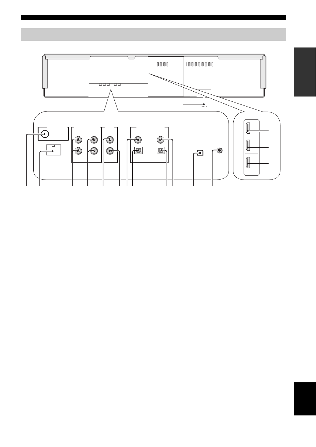
Rear panel
Controls and functions
The illustration below shows the rear panel of the U.S.A. and Canada models.
F
1
DOCK
AUDIO INPUTANTENNA
AUX 1 AUX 1
3
4
TV/STB
VIDEO
SUBWOOFER
5
6
1 ANTENNA jack
Connect the FM antenna (see page 29).
2 DOCK terminal
(U.S.A., Canada, and Australia models only)
Connect the Yamaha iPod universal dock (such as YDS10, sold separately) (see page 2 in the Reference Guide).
3 AUX 1 AUDIO INPUT jacks
Connect an external component via an analog connection
(see page 23).
4 TV/STB AUDIO INPUT jacks
Connect your TV, digital satellite tuner, or cable TV tuner
via an analog connection (see pages 22 and 24).
5 VIDEO OUT jack
Connect to the video input jack of your TV to display the
OSD of this unit (see page 22).
6 SUBWOOFER OUT jack
Connect your subwoofer (see page 28).
7 AUX 2 COAXIAL DIGITAL INPUT jack
Connect an external component via a coaxial digital
connection (see page 27).
8 AUX 1 OPTICAL DIGITAL INPUT jack
Connect an external component via an optical digital
connection (see page 27).
7
8
DIGITAL INPUTOUT
AUX 2
DVD
COAXIAL
OPTICAL
TV/STB
90
0 DVD COAXIAL DIGITAL INPUT jack
Connect your DVD player via a coaxial digital connection
(see page 23).
A XM antenna jack
(U.S.A and Canada models only)
Connect your XM Mini-Tuner Dock (sold separately)
(see page 5 in the Reference Guide).
B IR IN terminal
(U.S.A and Canada models only)
This is a control expansion terminal for commercial use
only (see page 29).
C AUX 1 HDMI IN jack
Connect your digital satellite tuner, cable TV tuner, digital
air wave tuner, or game console via an HDMI connection
(see page 21).
D DVD HDMI IN jack
Connect your DVD player via an HDMI connection (see
page 21).
E HDMI OUT jack
Connect to the HDMI IN jack on your HDMI component
such as a TV or a projector connected to this unit (see
page 21).
F AC power supply cable
Connect to the AC wall outlet (see page 29).
9 TV/STB OPTICAL DIGITAL INPUT jack
Connect your TV, digital satellite tuner, or cable TV tuner
via an optical digital connection (see pages 22 and 24).
A
AUX 1
DVD
IN
IR INXM
OUT
HDMI
B
(U.S.A. and Canada models)
INTRODUCTION
C
D
E
English
9 En
Controls and functions
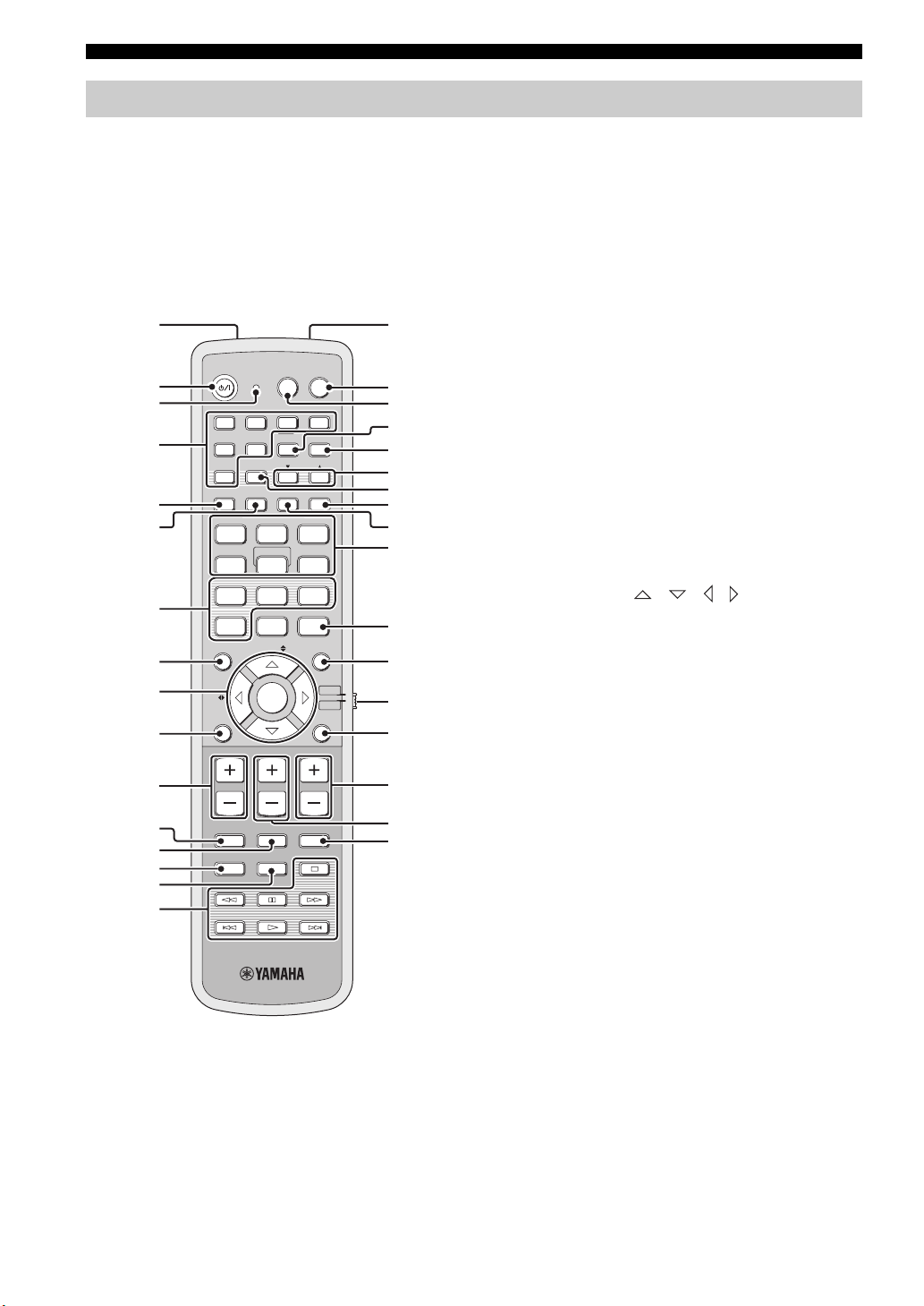
Remote control (Europe, Australia, Asia, and Korea models)
This section describes the functions of the remote control
used to control this unit. Some buttons marked with an
asterisk (*) share the common functions between the YSP
and TV/AV operation modes (S).
y
You can also control other components using the remote control
once you set the appropriate remote control codes. See
“Controlling other components” on page 97 for details.
1G
POWERPOWERSTANDBY/ON
INPUT1
INPUTMODE
5
CH
TVAV
AUX3
TV
MACRO
MEMORYSEARCH
SLEEP
321
MY SUR.
6
SPORTS
9
SUR. DECODE
TV/AV
RETURNDISPLAY
TV VOL
CODE SET
YSP
H
I
J
K
L
M
N
O
P
Q
R
S
t
U
V
W
*
*
*
*
*
*
2
*
3
DVD
AUX1 AUX2
4
*
5
6
7
TV
STB
PRESET/TUNE
A-E
FM
AUTO
SETUP
VOL MODE
5BEAM ST+3BEAM 3BEAM
STEREO
MY BEAM
4
MUSIC MOVIE
78
OFF
+10
0
ENHANCER MENU
ENTRY
8
9
A-E
ENTER
0
VOLUME
A
*
MUTE
B
*
C
*
D
TV INPUT TV MUTE
CH LEVEL TEST
E
F
1 Infrared window
Outputs infrared control signals. Aim this window at the
component you want to operate.
2 STANDBY/ON
Sets this system to the standby mode (see page 31).
3 Transmission indicator
Lights up when infrared control signals are being output.
4 Input selector buttons
Use to select an input source (DVD, AUX1, AUX2,
AUX3, STB, TV, or FM).
5 VOL MODE
Turns on or off the volume modes (see page 67).
6 AUTO SETUP
Enters the AUTO SETUP menu (see page 35).
7 CINEMA DSP program buttons
Select the CINEMA DSP programs (see page 63).
8 ENHANCER
Turns on or off the Music Enhancer (see page 66).
9 Cursor buttons / / / , ENTER
Select and adjust SET MENU items.
0 DISPLAY
Displays information on the selected input signal.
A VOLUME +/–
Increases or decreases the volume level of this unit (see
page 47).
B MUTE
Mutes the sound. Press again to restore the audio output to
the previous volume level (see page 47).
C TV INPUT
Toggles between the input sources on the TV (see
page 97).
D CH LEVEL
Adjusts the volume level of each channel (see page 85).
E TEST
Outputs a test tone when adjusting the output level of each
channel (see page 84).
10 En

Controls and functions
F DVD player/VCR control buttons
Control your DVD player or VCR (see pages 98 and 99).
G My Beam microphone
Collects the test tones from this unit when using the My
Beam auto-adjust function (see page 61).
H TV POWER
Turns on the power of your TV or sets it to the standby
mode (see page 97).
I AV POWER
Turns on the power of the selected component or sets it to
the standby mode (see pages 98 and 99).
J INPUT1
Switches the input source on your TV (see page 97).
K MACRO
Use to set the TV macro (see page 100).
L a /5
Switches the preset station number (1 to  when this unit
is receiving an FM broadcast (see page 52).
M A-E
Switches the preset station group (A to E) when this unit is
receiving an FM broadcast (see page 52).
N SLEEP
Sets the sleep timer (see page 68).
O INPUTMODE
Toggles between input modes (AUTO, DTS, and
ANALOG) (see page 87).
P Beam mode buttons
Change the beam mode settings (see pages 54, 60, and
61).
Q SUR. DECODE
Selects the surround mode for playback (see page 57).
R MENU
Displays the setup menu on your TV monitor (see
pages 37 and 73).
S Operation mode selector
Selects the operation mode of this unit. Select YSP when
operating this unit and select TV/AV when operating your
TV or other AV components.
T RETURN
Selects sleep timer settings or returns to the previous SET
MENU screen.
U TV VOL +/–
Adjusts the volume level of your TV (see page 97).
V CH +/–
Changes the channels of your TV, digital satellite tuner,
cable TV tuner, or VCR (see pages 97 and 99).
W TV MUTE, CODE SET
Mutes the audio output of your TV (see page 97).
Sets up remote control codes (see page 96).
Note
The functions L and M are available only when the FM stations
are preset.
INTRODUCTION
11 En
English
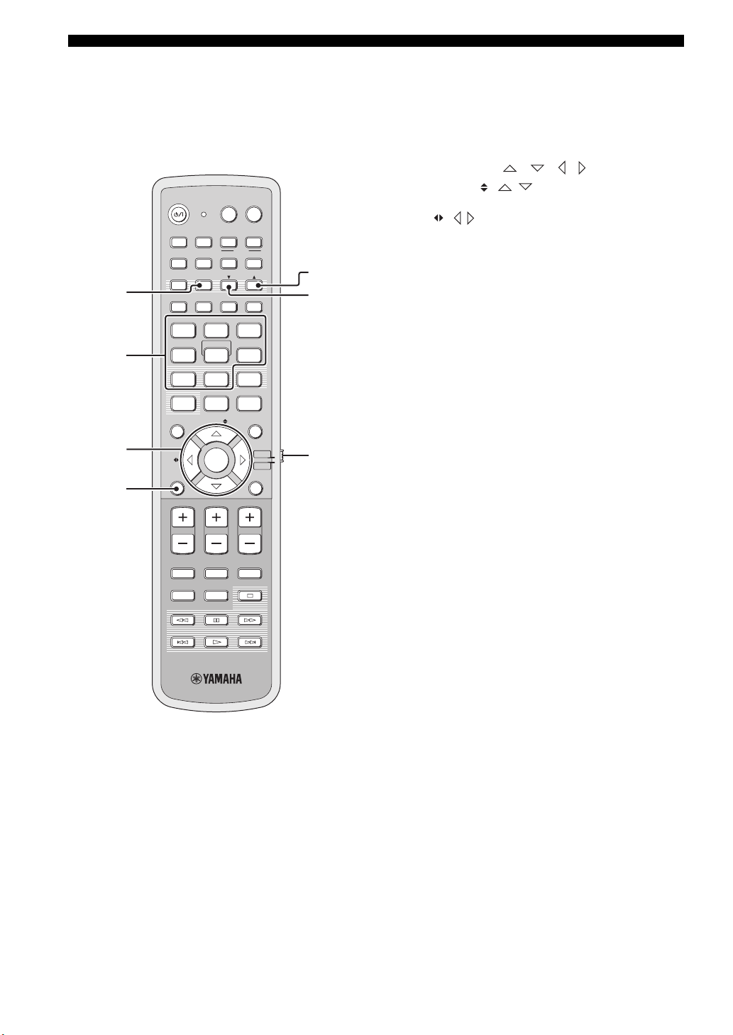
Controls and functions
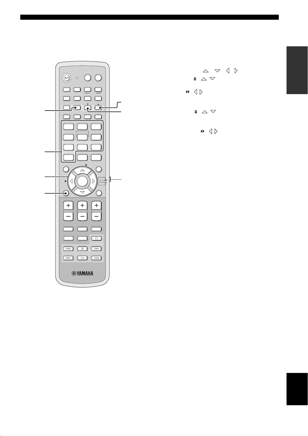
This section describes the functions of the remote control
used to control FM, Radio Data System, or iPod when the
TV/AV mode is selected with the operation mode selector
(7). Note that the Radio Data System controls are
available for Europe model only, and the iPod controls are
available for Australia model only.
POWERPOWERSTANDBY/ON
TVAV
DVD
1
2
3
AUX1 AUX2
TV
STB
PRESET/TUNE
A-E
FM
AUTO
SETUP
VOL MODE
5BEAM ST+3BEAM 3BEAM
STEREO
MY BEAM
4
MUSIC MOVIE
78
OFF
0
ENHANCER MENU
A-E
INPUTMODE
5
+10
ENTRY
ENTER
INPUT1
AUX3
TV
MACRO
MEMORYSEARCH
SLEEP
321
MY SUR.
6
SPORTS
9
SUR. DECODE
TV/AV
YSP
RETURNDISPLAY
5
6
7
4
VOLUME
MUTE
CH LEVEL TEST
TV VOL
CH
TV INPUT TV MUTE
CODE SET
1 PRESET/TUNE
FM: Switches between the preset search mode and the
frequency search mode (see pages 49 to 52).
2 Numeric buttons
FM: Enter numbers.
3 Cursor buttons / / / / ENTER
FM: Use ENTRY ( / ) to change the preset station
number (1 to or frequency level (see pages 49 to 52).
Use A-E ( / ) to change the preset station group (A to
E) (see pages 51 and 52). Use ENTER to confirm the input
above.
y
These functions are also available when this unit is receiving the
Radio Data System (see page 52) or playing back your iPod (see
page 3 in the Reference Guide).
4 DISPLAY
Radio Data System and iPod: Displays information when
this unit is receiving the Radio Data System (see page 52)
or playing back your iPod (see page 3 in the Reference
Guide).
5 MEMORY
FM: Stores the preset stations (see pages 50 and 51).
y
This function is also available when this unit is receiving the
Radio Data System (see page 52).
6 SEARCH
FM: Switches between automatic and manual tuning (see
page 49).
7 Operation mode selector
Selects the operation mode of this unit. Select YSP when
operating this unit and select TV/AV when operating your
TV or other AV components.
12 En
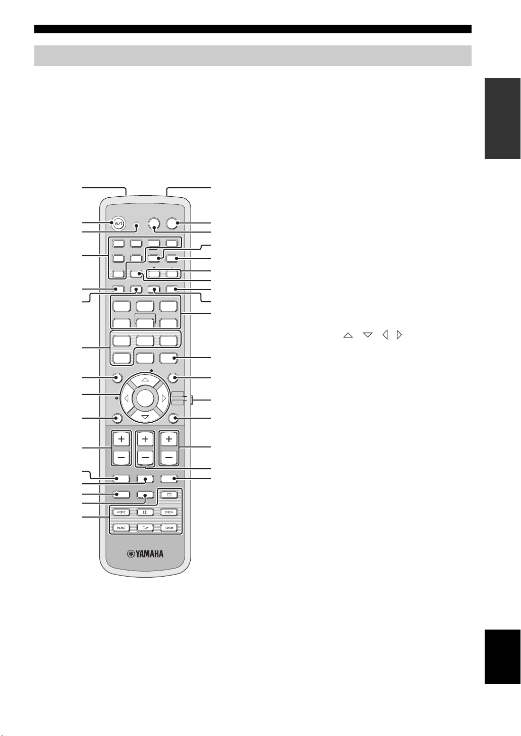
Remote control (U.S.A. and Canada models)
Controls and functions
This section describes the functions of the remote control
used to control this unit. Some buttons marked with an
asterisk (*) share the common functions between the YSP
and TV/AV operation modes (S).
y
You can also control other components using the remote control
once you set the appropriate remote control codes. See
“Controlling other components” on page 97 for details.
1G
POWERPOWERSTANDBY/ON
2
*
3
DVD
4
*
5
6
7
STB
VOL MODE
5BEAM ST+3BEAM
STEREO
4
MUSIC MOVIE
78
OFF
0
ENHANCER MENU
8
9
CAT/
A-E
0
VOLUME
A
*
B
*
C
*
D
MUTE
CH LEVEL TEST
AV
AUX1 AUX2
INPUT1
TV
PRESET/TUNE
CATFM/XM
AUTO
SETUP
INPUTMODE
MY BEAM
5
+10
ENTRY
ENTER
CH
TV INPUT TV MUTE
TV
DOCK
AUX3
TV
MACRO
MEMORYSEARCH
SLEEP
3BEAM
321
MY SUR.
6
SPORTS
9
SUR. DECODE
TV/AV
RETURNDISPLAY
TV VOL
CODE SET
YSP
H
I
J
K
L
M
N
O
P
Q
R
S
t
U
V
W
*
*
*
*
*
*
E
F
1 Infrared window
Outputs infrared control signals. Aim this window at the
component you want to operate.
2 STANDBY/ON
Sets this system to the standby mode (see page 31).
3 Transmission indicator
Lights up when infrared control signals are being output.
4 Input selector buttons
Use to select an input source (DVD, AUX1, AUX2,
AUX3/DOCK, STB, TV, or FM/XM).
5 VOL MODE
Turns on or off the volume modes (see page 67).
6 AUTO SETUP
Enters the AUTO SETUP menu (see page 35).
7 Sound field program buttons
Select the sound field programs (see page 63).
8 ENHANCER
Turns on or off the Music Enhancer (see page 66).
9 Cursor buttons / / / , ENTER
Select and adjust SET MENU items.
0 DISPLAY
Displays information on the selected input signal.
A VOLUME +/–
Increases or decreases the volume level of this unit (see
page 47).
B MUTE
Mutes the sound. Press again to restore the audio output to
the previous volume level (see page 47).
C TV INPUT
Toggles between the input source on your TV (see
page 97).
D CH LEVEL
Adjusts the volume level of each channel (see page 85).
E TEST
Outputs a test tone when adjusting the output level of each
channel (see page 84).
INTRODUCTION
13 En
English

Controls and functions
F DVD player/VCR control buttons
Control your DVD player or VCR (see pages 98 and 99).
G My Beam microphone
Collects the test tones from this unit when using the My
Beam auto-adjust function (see page 61).
H TV POWER
Turns on the power of your TV or sets it to the standby
mode (see page 97).
I AV POWER
Turns on the power of the selected component or sets it to
the standby mode (see pages 98 and 99).
J INPUT1
Switches the input source on your TV (see page 97).
K MACRO
Use to set the TV macro (see page 100).
L a /5
Switches the preset station number (1 to when this unit
is receiving an FM broadcast or XM channel (see
page 52).
M CAT
Switches the preset station group (A to E) when this unit is
receiving an FM broadcast or XM channel (see page 52).
N SLEEP
Sets the sleep timer (see page 68).
T RETURN
Selects sleep timer settings or returns to the previous SET
MENU screen.
U TV VOL +/–
Adjusts the volume level of your TV (see page 97).
V CH +/–
Changes the channels of your TV, digital satellite tuner,
cable TV tuner, or VCR (see pages 97 and 99).
W TV MUTE, CODE SET
Mutes the audio output of your TV (see page 97).
Sets up remote control codes (see page 96).
Note
The functions L and M are available only when the FM/XM
stations are preset.
O INPUTMODE
Toggles between input modes (AUTO, DTS, and
ANALOG) (see page 87).
P Beam mode buttons
Change the beam mode settings (see pages 54, 60, and
61).
Q SUR. DECODE
Selects the surround mode for playback (see page 57).
R MENU
Displays the setup menu on your TV monitor (see
pages 37 and 73).
S Operation mode selector
Selects the operation mode of this unit. Select YSP when
operating this unit and select TV/AV when operating your
TV or other AV components.
14 En
Controls and functions
This section describes the functions of the remote control
used to control FM, XM Satellite Radio, or iPod when the
TV/AV mode is selected with the operation mode selector
(7).
POWERPOWERSTANDBY/ON
AV
TV
1
2
3
AUX1 AUX2
DVD
TV
STB
PRESET/TUNE
CATFM/XM
AUTO
SETUP
VOL MODE
5BEAM ST+3BEAM 3BEAM
STEREO
4
MUSIC MOVIE
78
OFF
0
ENHANCER MENU
CAT/
A-E
INPUTMODE
MY BEAM
5
+10
ENTRY
ENTER
INPUT1
DOCK
AUX3
TV
MACRO
MEMORYSEARCH
SLEEP
321
MY SUR.
6
SPORTS
9
SUR. DECODE
TV/AV
RETURNDISPLAY
YSP
5
6
7
4
VOLUME
MUTE
CH LEVEL TEST
TV VOL
CH
TV INPUT TV MUTE
CODE SET
1 PRESET/TUNE
FM: Switches between the preset search mode and the
frequency search mode (see pages 49 to 52).
2 Numeric buttons
FM, XM: Enter numbers.
3 Cursor buttons / / /
FM: Use ENTRY ( / ) to change the preset station
number (1 to or frequency level (see pages 49 to 52).
Use CAT/A-E ( / ) to change the preset station group
(A to E) (see pages 51 and 52). Use ENTER to confirm the
input above.
XM: Use ENTRY ( / ) to select XM channels in
All Channel Search mode/Category Search mode, and to
select the preset channel number (1 to in Preset Search
mode. Use CAT/A-E ( / ) to select XM categories in
All Channel Search mode/Category Search mode, and to
select the preset channel group (A to E) in Preset Search
mode. Use ENTER to confirm the input above (see pages
7 and 8 in the Reference Guide).
y
These functions are also available when this unit is playing back
your iPod (see page 3 in the Reference Guide).
4 DISPLAY
XM and iPod: Displays information when this unit is
receiving an XM channel (see page 10 in the Reference
Guide) or playing back your iPod (see page 3 in the
Reference Guide).
5 MEMORY
FM: Stores the preset stations (see pages 50 and 51).
XM: Use to store the preset stations (see page 9 in the
Reference Guide).
6 SEARCH
FM: Switches between automatic and manual tuning (see
page 49).
XM: Switches between search modes (All Channel
Search, Category Search, and Preset Search) (see pages 7
and 8 in the Reference Guide).
7 Operation mode selector
Selects the operation mode of this unit. Select YSP when
operating this unit and select TV/AV when operating your
TV or other AV components.
INTRODUCTION
15 En
English
Installation
Installation
This section describes a suitable installation location to install this unit using a metal wall bracket, a rack or a stand.
Depending on your installation environment, connections with external components can be done before installing this
unit. We recommend that you temporarily place and arrange all components, including this unit, in order to decide which
procedure should come first. Especially when you make a connection over HDMI, we recommend that you make a
connection first before installation (see page 21).
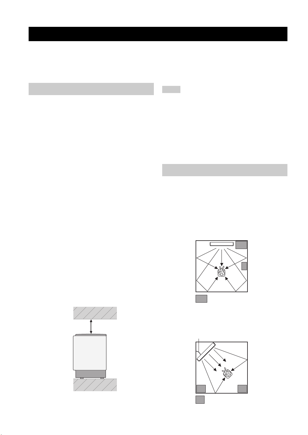
Before installing this unit
This unit creates surround sound by reflecting projected
sound beams off the walls of your listening room. The
surround sound effects produced by this unit may not be
sufficient when this unit is installed in the following
locations.
• Rooms with walls inadequate for reflecting sound
beams
• Rooms with acoustically absorbent walls
• Rooms with measurements outside the following
range: W (3 to 7 m (10 to 23 ft)) x H (2 to 3.5 m (7 to
11.5 ft)) x D (3 to 7 m (10 to 23 ft))
• Rooms with less than 1.8 m (6 ft) from the listening
position to this unit
• Rooms where objects such as furniture are likely to
obstruct the path of sound beams
• Rooms where the listening position is close to the walls
• Rooms where the listening position is not in front of
this unit
y
• You can enjoy surround sound by selecting My Surround (see
page 55) as the beam mode even if your listening room may not
fulfill the above conditions (except when the listening position
is not directly facing toward the front of this unit).
• You can also enjoy surround sound by selecting 2-channel or 5-
channel stereo playback (see page 60) or My Beam (see
page 61) as the beam mode even if your listening room may not
fulfill the above conditions.
Make sure you leave an adequate amount of ventilation
space so that heat can escape. Make at least 5 cm (2 in) of
space above or below this unit.
Side view
Notes
• We do not recommend putting this unit directly on the floor of
your listening room. Please install this unit using a metal wall
bracket, a rack, or a stand.
• This unit weighs 11.5 kg (25 lbs 6 oz). Be sure to install this
unit where it will not fall subject to vibrations, such as from an
earthquake, and where it is out of the reach of children.
• When using a cathode-ray tube (CRT) TV, do not install this
unit directly above your TV.
• This unit is shielded against magnetic rays. However, if the
picture on your TV screen becomes blurred or distorted, we
recommend moving this unit away from your TV.
Installing this unit
Install this unit where there are no obstacles such as
furniture obstructing the path of sound beams. Otherwise,
the desired surround sound effects may not be achieved.
You may install this unit in parallel with the wall or in the
corner.
Parallel installation
Install this unit in the exact center of the wall when it is
measured from the left and right corners.
An object, such as furniture
16 En
Front
5 cm (2 in) or more
Rear
Corner installation
Install this unit in the corner at a 40º to 50º angle from the
adjacent walls.
40° to 50°
An object, such as furniture
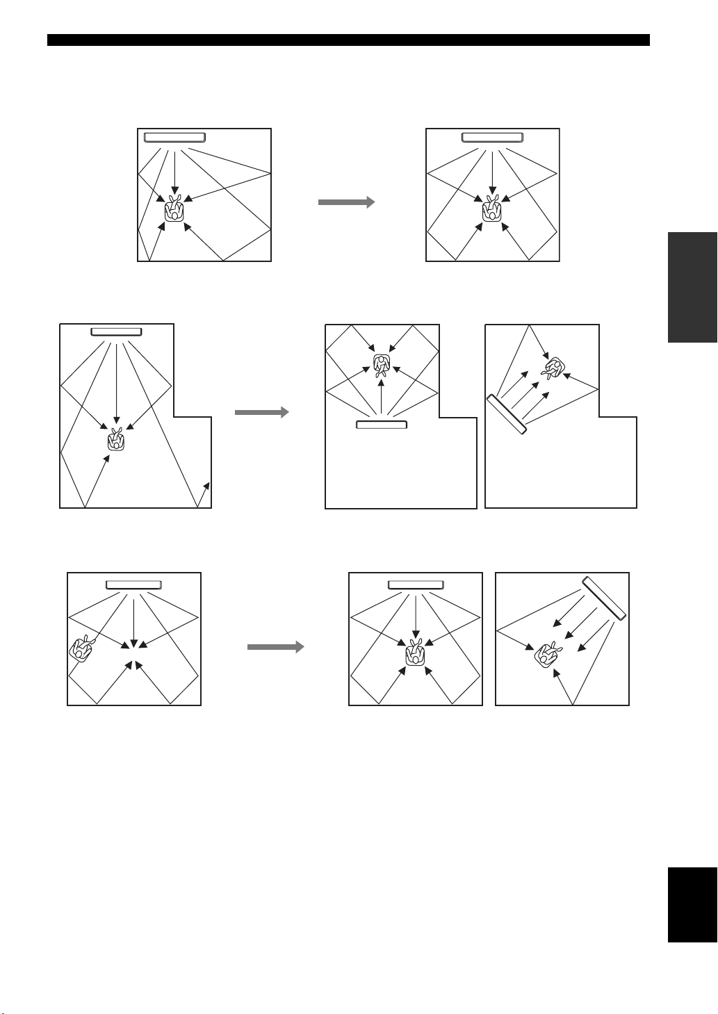
■ Installation examples
Example 1
Install this unit as close to the exact center of the wall as possible.
Example 2
Install this unit so that the sound beams can be reflected off the walls.
Installation
PREPARATION
Example 3
Install this unit as close to the exact front of your normal listening position as possible.
English
17 En
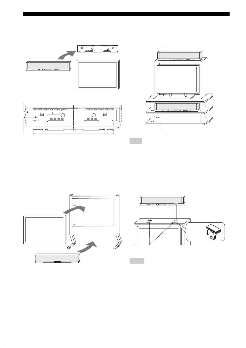
Installation
■ Using a metal wall bracket
You can use the optional metal wall bracket to mount this
unit on the wall in your listening room.
Metal wall bracket
This unit
TV
YSP-3000
65
SPM-K30 (Option)
325 65325
24- 7×22
670
92
4- 7
y
Refer to the instructions supplied with the metal bracket for
details on how to attach the metal bracket to the wall or how to
attach this unit to the metal bracket.
■ Using a stand
You can mount your TV on a stand placed on a
commercially available rack and install this unit under
your TV.
Stand
■ Using a rack
You can install this unit either above or under your TV in a
commercially available rack.
When this unit is installed above your TV
112
When this unit is installed under your TV
Note
Make sure that the rack is large enough to allow adequate
ventilation space around this unit (see page 16) and that it is
strong enough to support the weight of both this unit and your TV.
■ Affixing this unit
Peel off the film from each of the four supplied fasteners
and then secure them to the bottom four corners of this
unit and the top of the rack, etc.
This unit
TV
This unit
y
Refer to the instructions supplied with the stand for details on
how to install the stand or how to mount and the TV on the stand.
18 En
Fasteners
Peel off
the film
2
1
Notes
• Do not install this unit on top of a slanted surface. This unit may
fall over and cause injury.
• Make sure you wipe the surface of the rack, etc. before securing
the fasteners. Applying the tape to a dirty or wet surface will
weaken the sticking power of the tape, and this unit may fall as
a result.
Connections
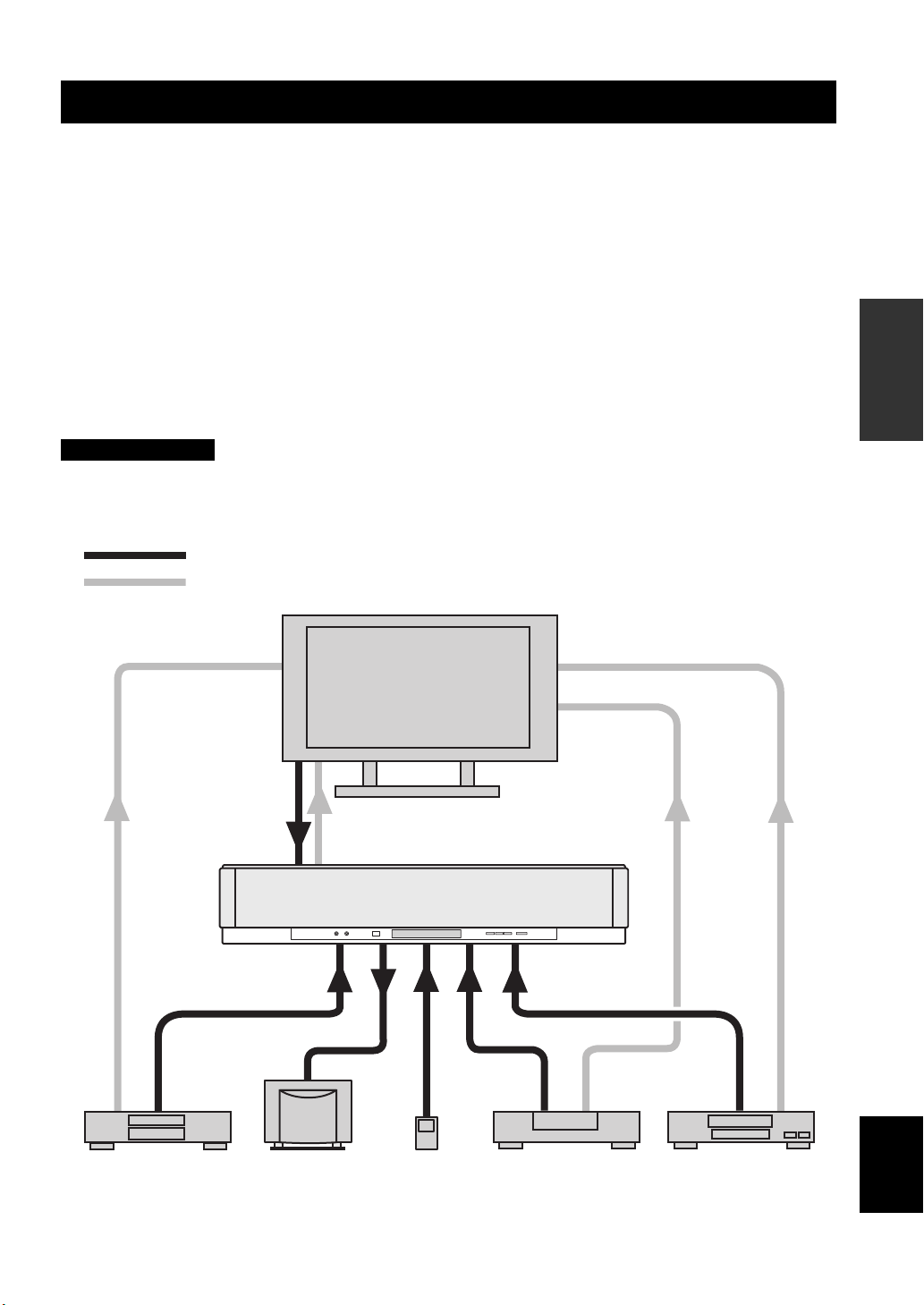
Connections
This unit is equipped with the following types of audio/video input/output jacks/terminal:
For audio input
• 2 optical digital input jacks
• 2 coaxial digital input jacks
• 2 sets of analog input jacks
• 1 universal dock terminal
(U.S.A., Canada, and Australia models only)
For audio/video input
• 2 HDMI input jacks
Use these jacks/terminal to connect external components such as your TV, DVD player, VCR, digital satellite tuner, cable
TV tuner, digital air wave tuner, portable audio player, game console, and iPod. Further, by connecting a subwoofer to
this unit, you can enjoy reinforced low-bass sounds. For details on how to connect various types of external components
to this unit, see pages 21 to 28.
CAUTION
• Do not connect this unit or other components to the mains power until all connections between components are
complete.
• Unplug the AC power supply cable before changing connections, moving or cleaning this unit.
Audio connection
Video connection
TV
For audio output
• 1 subwoofer output jack
For audio/video output
• 1 HDMI output jack
For video output
• 1 analog output jack
PREPARATION
This unit
portable audio
player
English
VCR or game consoleDVD player Subwoofer Digital satellite tuner
or cable TV tuner
19 En
Connections
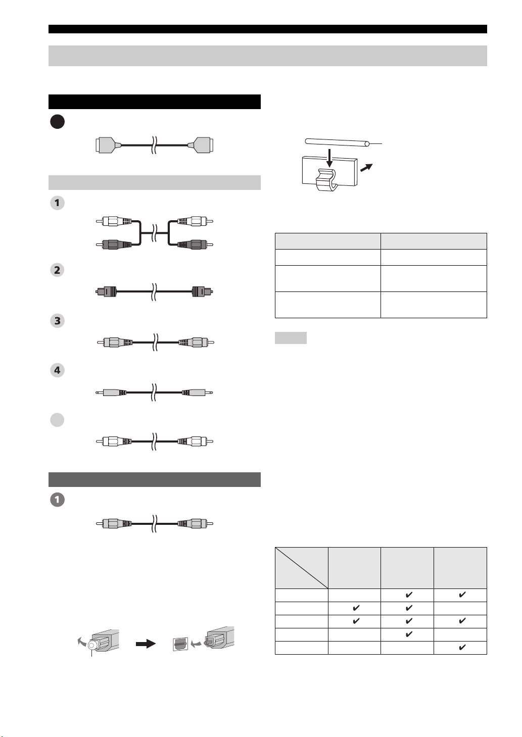
Before connecting components
■ Cables used for connections
Audio/Video
HDMI cable
A
Audio
Audio pin cable (supplied)
(White)
(Red)
Optical cable (supplied)
Digital audio pin cable (supplied)
3.5 mm stereo mini plug cable
Subwoofer pin cable
5
(White)
(Red)
(Orange)(Orange)
■ Affixing cables
To prevent cables from becoming unplugged, place the
supplied cable clamp with the open side facing upward,
attach it to the rear panel of this unit in a suitable position,
and then affix cables in the cable clamp.
Optical cable
Attach to this unit
■ Information on HDMI™
Audio Signals
Input source Audio signal type
DVD video Dolby Digital, DTS, PCM
DVD audio
Blu-ray Disc
HD DVD
Notes
• When CPPM copy-protected DVD audio is played back, video
and audio signals may not be output depending on the type of
DVD player.
• This unit is not compatible with HDCP-incompatible HDMI or
DVI components.
y
• We recommend that you use an HDMI cable shorter than 5 m
(16 ft) with the HDMI logo printed on it.
• Use a conversion cable (HDMI jack
this unit to other DVI components.
2-channel stereo
(up to 96 kHz/24 bit)
Dolby Digital, DTS, PCM
↔ DVI-D jack) to connect
Video
OSD video pin cable (supplied)
(Yellow)(Yellow)
■ Notes on connecting the optical cable
• Pull out the cap before connecting the optical cable.
When you are not using the optical cable, be sure to put
the cap back in place.
• When inserting the cable into the optical digital jack,
make sure the direction is correct.
Cap
20 En
■ Priority order for audio input signals
When multiple types of audio signals are simultaneously
being input from a single source component, this unit
plays back the audio signals in the following priority
order: HDMI → Digital → Analog
As default settings, the following input jacks are assigned
to the corresponding input sources:
Input
Input
source
TV/STB
DVD
AUX 1
AUX 2
AUX 3
jack
HDMI Digital Analog
Connections
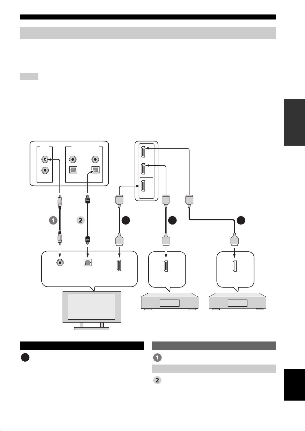
Connections using HDMI cables
This unit is equipped with 2 HDMI input jacks and 1 HDMI output jack. If your TV and other components have HDMI
jacks, use HDMI cables for simpler and easier connections, and you can skip the connection procedures from page 22 to
25. If your TV has a built-in digital satellite tuner and an optical digital output jack, connect the optical digital output jack
on your TV to the TV/STB OPTICAL DIGITAL INPUT jack on this unit.
Notes
• Even if you connect your TV and this unit via the HDMI jack, you need to connect the video input jack on your TV to the VIDEO
OUT jack on this unit in order to display the OSD of this unit.
• When HDMI CONTROL is set to OFF (see page 82) and this unit is in the standby mode, the signals input at the HDMI IN jacks are
not output at the HDMI OUT jack.
y
We recommend that you secure the HDMI cable(s) with adhesive tape, etc. once you have connected the HDMI cable(s) to the HDMI
jack(s) of this unit.
Rear panel of this unit
PREPARATION
VIDEO
SUBWOOFER
Video
input
DIGITAL INPUTOUT
AUX 2
AUX 1
COAXIAL
OPTICAL
TV/STB
Optical
digital
input
TV
DVD
AUX 1
DVD
IN
OUT
HDMI
A AA
HDMI
input
HDMI
output
DVD player/recorder
*
This connection (except for a game
console) is not necessary if your
TV has a built-in digital satellite
tuner, cable TV tuner, or digital
airwave tuner.
HDMI
output
Digital satellite tuner,
cable TV tuner,
digital airwave tuner,
or game console
Audio/Video
HDMI cable OSD video pin cable
A
Optical cable
Video
Audio
English
21 En
Connections
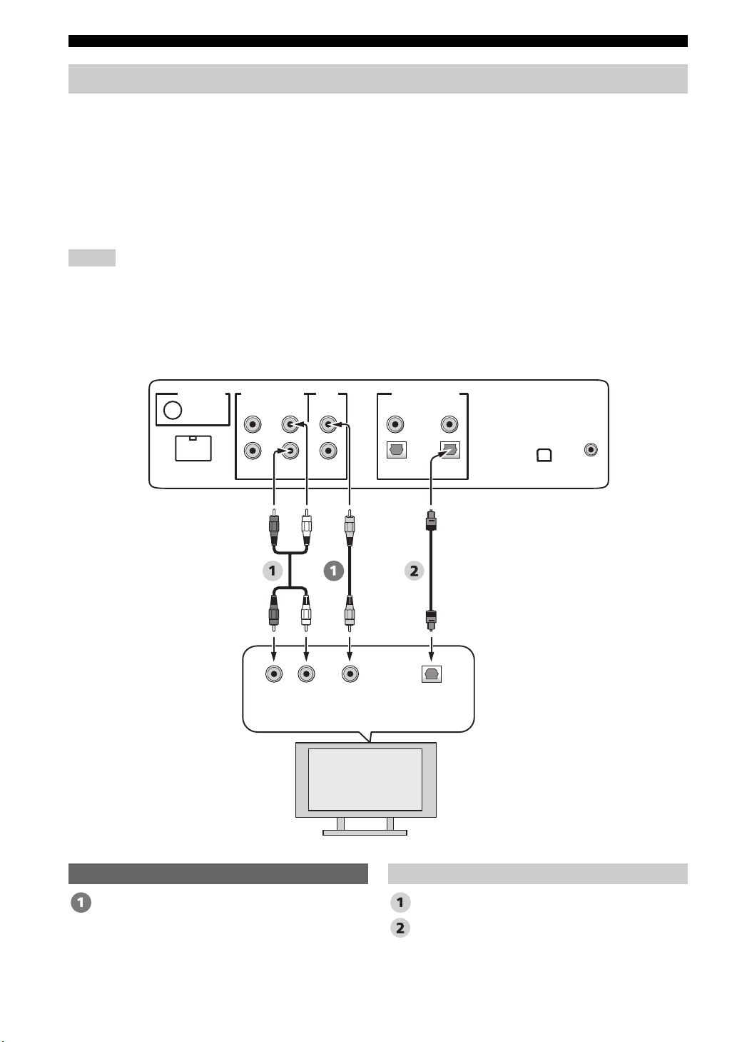
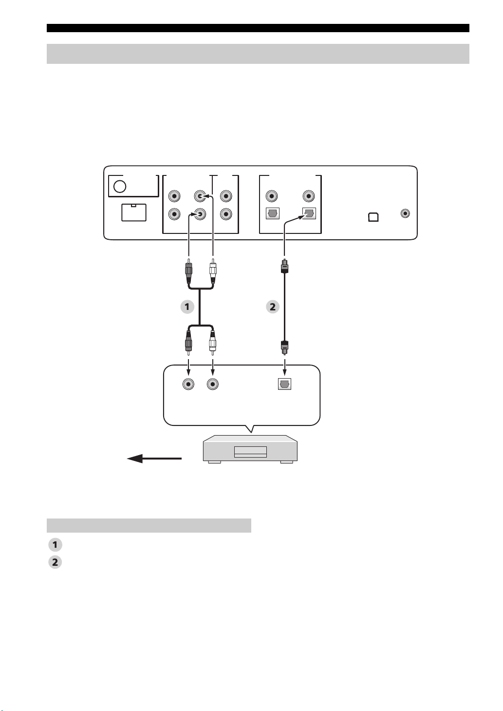
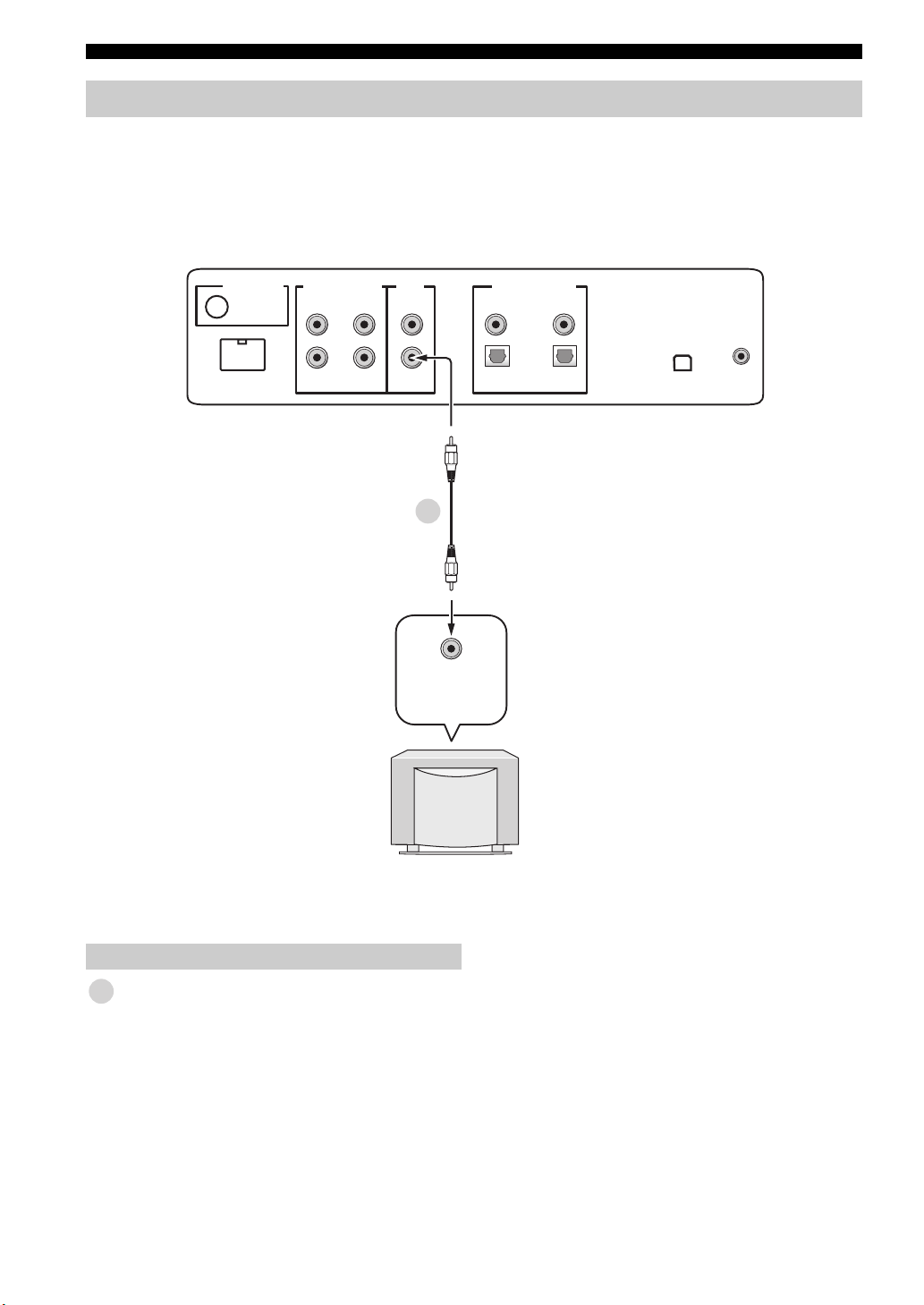
Connecting a TV
For audio connection, connect the analog audio output jacks on your TV to the TV/STB AUDIO INPUT jacks on this
unit. If your TV has an optical digital output jack, connect the optical digital output jack on your TV to the TV/STB
OPTICAL DIGITAL INPUT jack on this unit.
For video connection, connect the video input jack on your TV to the VIDEO OUT jack on this unit to display the OSD
for easy viewing when you adjust the system parameters in SET MENU.
y
To prevent the optical cable from being unplugged, affix the optical cable in the supplied cable clamp (see page 20).
Notes
• If you make analog and optical digital audio connections at the same time as shown in the illustration below, the digital audio signals
input at the TV/STB OPTICAL DIGITAL INPUT jack take priority over the analog audio signals input at the TV/STB AUDIO
INPUT jacks.
• Even if you connect your TV and this unit via the HDMI jack, you need to connect the video input jack on your TV to the VIDEO
OUT jack on this unit in order to display the OSD of this unit.
Rear panel of this unit
(U.S.A. and Canada models)
DOCK
AUDIO INPUTANTENNA
AUX 1 AUX 1
RL
Analog
output
TV/STB
audio
VIDEO
SUBWOOFER
Video
input
DIGITAL INPUTOUT
AUX 2
DVD
COAXIAL
OPTICAL
TV/STB
Optical
digital
output
IR INXM
TV
Video Audio
OSD video pin cable Audio pin cable
Optical cable
22 En
Connections
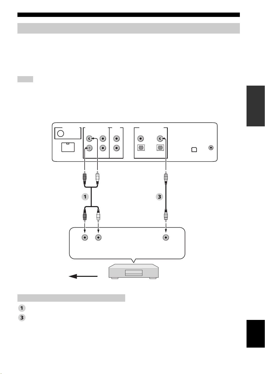
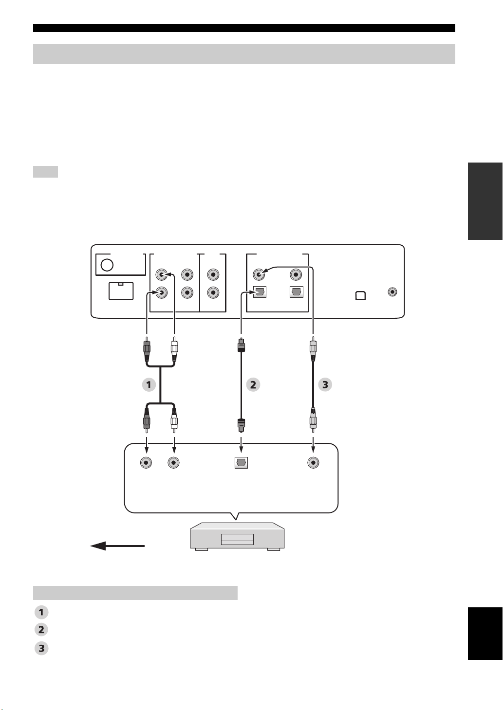
Connecting a DVD player/recorder
Connect the coaxial digital output jack on your DVD player/recorder to the DVD COAXIAL DIGITAL INPUT jack on
this unit. When you connect this unit to your DVD/VCR combo player/recorder, connect the analog audio output jacks on
your DVD/VCR combo player/recorder to the AUX 1 AUDIO INPUT jacks on this unit in addition to the coaxial digital
audio connection.
y
To prevent the optical cable from being unplugged, affix the optical cable in the supplied cable clamp (see page 20).
Notes
• Check that your DVD player/recorder is properly set to output Dolby Digital and DTS digital audio signals. If not, adjust the system
settings of your DVD player/recorder. For details, refer to the operation manual supplied with your DVD player/recorder.
• If your DVD player/recorder does not have a coaxial digital output jack, make an optical digital audio connection instead (see
page 27).
Rear panel of this unit
(U.S.A. and Canada models)
PREPARATION
DOCK
AUDIO INPUTANTENNA
AUX 1 AUX 1
*
LR
Analog
audio
output
VIDEO
SUBWOOFER
TV/STB
For the DVD/VCR combo
player/recorder
connection
AUX 2
DIGITAL INPUTOUT
DVD
COAXIAL
OPTICAL
TV/STB
Coaxial
digital
output
IR INXM
Video signal to the TV
Audio
Audio pin cable
Digital audio pin cable
DVD player/recorder
English
23 En
Connections
Connecting a digital satellite tuner or a cable TV tuner
Connect the optical digital output jack on your digital satellite tuner or cable TV tuner to the TV/STB OPTICAL
DIGITAL INPUT jack on this unit. Connect the analog audio output jacks on your digital satellite tuner or cable TV
tuner to the TV/STB AUDIO INPUT jacks on this unit.
y
To prevent the optical cable from being unplugged, affix the optical cable in the supplied cable clamp (see page 20).
Rear panel of this unit
(U.S.A. and Canada models)
DOCK
AUDIO INPUTANTENNA
AUX 1 AUX 1
Analog
TV/STB
LR
audio
output
VIDEO
SUBWOOFER
DIGITAL INPUTOUT
AUX 2
Optical
digital
output
DVD
COAXIAL
OPTICAL
TV/STB
IR INXM
Video signal to the TV
*
This connection (except for a game console) is not
necessary if your TV has a built-in digital satellite
tuner, cable TV tuner, or digital airwave tuner.
Audio
Audio pin cable
Optical cable
24 En
Digital satellite tuner
or cable TV tuner
Connections
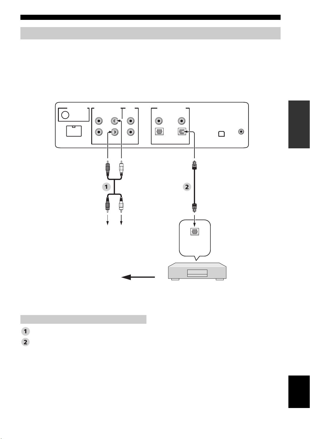
Connecting a digital airwave tuner
Connect the TV/STB AUDIO INPUT jacks on this unit to the analog audio output jacks on your TV. Connect the optical
digital output jack on your digital airwave tuner to the TV/STB OPTICAL DIGITAL INPUT jack on this unit in addition
to the analog audio connection. By doing so, you can enjoy both analog and digital broadcasts.
y
To prevent the optical cable from being unplugged, affix the optical cable in the supplied cable clamp (see page 20).
Rear panel of this unit
(U.S.A. and Canada models)
DIGITAL INPUTOUT
AUX 2
DVD
COAXIAL
OPTICAL
TV/STB
IR INXM
DOCK
AUDIO INPUTANTENNA
AUX 1 AUX 1
TV/STB
VIDEO
SUBWOOFER
PREPARATION
*
Audio pin cable
Optical cable
Connect to the analog
audio output jacks on
the TV.
Video signal to the TV
This connection (except for a game console) is not
necessary if your TV has a built-in digital satellite
tuner, cable TV tuner, or digital airwave tuner.
Audio
Optical
digital
output
Digital airwave tuner
English
25 En
Connections
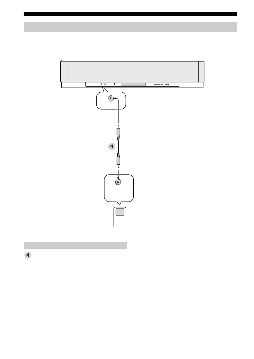
Connecting a portable audio player
Connect the analog audio output jack on your portable audio player to the AUX 3 input jack on the front panel of this
unit.
Front panel of this unit
AUX 3
Audio
3.5 mm stereo mini plug cable
Analog
audio
output
Portable audio player
26 En
Connections
Connecting other external components
If your component supports optical digital connections, connect the optical digital output jack on your component
(e.g., DVD player/recorder) to the AUX 1 OPTICAL DIGITAL INPUT jack on this unit. If your component does not
support optical digital connections, connect the coaxial digital output jack on your component to the AUX 2 COAXIAL
DIGITAL INPUT jack on this unit.
If your component does not support any digital connections, connect the analog audio output jacks on your component
(e.g., VCR) to the AUX 1 AUDIO INPUT jacks on this unit.
y
To prevent the optical cable from being unplugged, affix the optical cable in the supplied cable clamp (see page 20).
Note
If you make analog and digital audio connections at the same time as shown in the illustration below, the digital audio signals input at
the AUX 1 OPTICAL DIGITAL INPUT or AUX 2 COAXIAL DIGITAL INPUT jack take priority over the analog audio signals input
at the AUX 1 AUDIO INPUT jacks.
Rear panel of this unit
(U.S.A. and Canada models)
PREPARATION
DOCK
AUDIO INPUTANTENNA
AUX 1 AUX 1
LR
Analog
audio
output
TV/STB
VIDEO
SUBWOOFER
Optical
digital
output
DIGITAL INPUTOUT
AUX 2
DVD
COAXIAL
OPTICAL
TV/STB
Coaxial
digital
output
IR INXM
Video signal to the TV
Audio
Audio pin cable
Optical cable
Digital audio pin cable
DVD player/recorder, VCR,
game console, CD player, etc.
English
27 En
Connections
Connecting a subwoofer
Connect the monaural input jack on your subwoofer to the SUBWOOFER OUT jack on this unit.
This connection alone does not output sound from the connected subwoofer. To output sound from the connected
subwoofer, turn on the power of your subwoofer and then run AUTO SETUP (see page 35) or select SWFR for BASS
OUT in SUBWOOFER SET (see page 78).
Rear panel of this unit
(U.S.A. and Canada models)
DOCK
AUDIO INPUTANTENNA
AUX 1 AUX 1
TV/STB
VIDEO
SUBWOOFER
DIGITAL INPUTOUT
AUX 2
5
Monaural
input
COAXIAL
OPTICAL
TV/STB
DVD
IR INXM
Subwoofer pin cable
5
28 En
Subwoofer
Audio
Loading…
- Topics
- manualsbase, manuals,
- Collection
- yamaha_bike_manuals; manuals; additional_collections
- Language
- English
- Item Size
- 4.0M
- Addeddate
- 2020-08-16 14:21:21
- Identifier
- manualsbase-id-434951
- Identifier-ark
- ark:/13960/t47q8503v
- Ocr
- ABBYY FineReader 11.0 (Extended OCR)
- Ppi
- 600
- Scanner
- Internet Archive Python library 1.9.4
plus-circle Add Review
plus-circle Add Review
comment
Reviews
There are no reviews yet. Be the first one to
write a review.
76
Views
DOWNLOAD OPTIONS
download 1 file
ABBYY GZ download
Temporarily Unavailable
DAISY
For users with print-disabilities
Temporarily Unavailable
EPUB
download 1 file
FULL TEXT download
download 1 file
ITEM TILE download
download 1 file
PAGE NUMBERS JSON download
download 1 file
PDF download
download 1 file
SINGLE PAGE PROCESSED JP2 ZIP download
download 1 file
TORRENT download
download 12 Files
download 6 Original
SHOW ALL
IN COLLECTIONS
Manuals: Yamaha Manuals
The Manual Library
Additional Collections
Uploaded by
chris85
on

YSP-3000
YAMAHA ELECTRONICS CORPORATION, USA
6660 ORANGETHORPE AVE., BUENA PARK, CALIF. 90620, U.S.A.
YAMAHA CANADA MUSIC LTD.
135 MILNER AVE., SCARBOROUGH, ONTARIO M1S 3R1, CANADA
YAMAHA ELECTRONIK EUROPA G.m.b.H.
SIEMENSSTR. 22-34, 25462 RELLINGEN BEI HAMBURG, GERMANY
YAMAHA ELECTRONIQUE FRANCE S.A.
RUE AMBROISE CROIZAT BP70 CROISSY-BEAUBOURG 77312 MARNE-LA-VALLEE CEDEX02, FRANCE
YAMAHA ELECTRONICS (UK) LTD.
YAMAHA HOUSE, 200 RICKMANSWORTH ROAD WATFORD, HERTS WD18 7GQ, ENGLAND
YAMAHA SCANDINAVIA A.B.
J A WETTERGRENS GATA 1, BOX 30053, 400 43 VÄSTRA FRÖLUNDA, SWEDEN
YAMAHA MUSIC AUSTRALIA PTY, LTD.
17-33 MARKET ST., SOUTH MELBOURNE, 3205 VIC., AUSTRALIA
2007 All rights reserved.
Printed in Malaysia WK75380
YSP-3000
Digital Sound Projector
TM
OWNER’S MANUAL
UA
00cv_YSP-3000_UA.fm Page 1 Thursday, August 2, 2007 11:19 AM
Yamaha YSP-3000 Reference Guide
Reference Guide
12 pages
en
Owner’s Manual
129 pages
en
Yamaha YSP-3000 Projector Specification
The Yamaha YSP-3000 is an advanced digital sound projector that blends cutting-edge technology with sophisticated audio performance. It uses a unique array of 21 beam drivers, each powered by a discrete 2-watt amplifier, to deliver a total output of 82 watts. This setup creates an immersive surround sound experience by precisely directing sound beams around the room, eliminating the need for multiple speakers. The YSP-3000 supports Dolby Digital, DTS, and Dolby Pro Logic II, ensuring compatibility with numerous audio formats. It features IntelliBeam automated calibration, which optimizes sound parameters based on room acoustics, resulting in a tailored audio experience. HDMI connectivity is included with two inputs and one output, supporting 1080p video signals for seamless integration with high-definition sources. Additionally, the unit offers analog and digital audio inputs, including optical and coaxial, enhancing its versatility. A built-in FM tuner with 40 preset stations provides added convenience for radio enthusiasts. The YSP-3000 incorporates Yamaha’s proprietary Compressed Music Enhancer, which restores lost audio quality in compressed music files, delivering richer sound. Its slim design, measuring approximately 3.5 inches in height, allows for easy placement in front of flat-panel TVs without obstructing the screen. The minimalist black finish complements modern home theater aesthetics. User-friendly controls are accessible via an intuitive on-screen display and a comprehensive remote control. The Yamaha YSP-3000 is designed for those seeking a high-quality, clutter-free home audio solution, making it an ideal choice for enhancing the acoustic environment of any living space.
Yamaha YSP-3000 Projector F.A.Q.
To set up the Yamaha YSP-3000, start by connecting the power cable and HDMI or optical audio cables to your devices. Use the on-screen setup guide accessible via the remote control to configure your audio and video settings.
Ensure that all cables are securely connected and that the correct input source is selected. Check the volume settings on both the projector and the connected device. If the issue persists, try resetting the projector to factory settings.
Visit the Yamaha support website to download the latest firmware update. Follow the instructions included with the update to install it via a USB drive. Ensure the projector is powered on during the update process.
Use a soft, dry cloth to wipe the exterior of the projector. Avoid using liquid cleaners or solvents. For the lens, a special lens cleaning solution and microfiber cloth are recommended.
Check the focus settings and make sure the projector is at the correct distance from the screen. Ensure the lens is clean and the resolution settings match the source device.
The YSP-3000 does not have built-in network capabilities. For wireless audio streaming, consider using a compatible external device such as a Bluetooth adapter.
Check the batteries and replace them if necessary. Ensure there are no obstructions between the remote and the projector. If the issue persists, try resetting the remote by removing the batteries and pressing all buttons.
To perform a factory reset, press and hold the power button on the unit for about 10 seconds until it resets. This will restore all settings to their defaults.
Yes, a universal remote can be programmed to work with the YSP-3000. Refer to the universal remote’s manual for instructions on entering the appropriate device codes.
Regularly dust the exterior and ensure the ventilation slots are clear of obstructions. Periodically check for firmware updates and clean the lens to maintain optimal performance.