

For more product details, please visit GIGABYTE’s website.
To reduce the impacts on global warming, the packaging materials of this product
are recyclable and reusable. GIGABYTE works with you to protect the environment.
Z690 AORUS PRO
Z690 AORUS PRO DDR4
User’s Manual
Rev. 1001
12ME-Z69PRO4-1001R
Z690 AORUS
PRO
Z690 AORUS
PRO DDR4
Copyright
© 2021 GIGA-BYTE TECHNOLOGY CO., LTD. All rights reserved.
The trademarks mentioned in this manual are legally registered to their respective owners.
Disclaimer
Information in this manual is protected by copyright laws and is the property of GIGABYTE.
Changes to the specications and features in this manual may be made by GIGABYTE without
prior notice. No part of this manual may be reproduced, copied, translated, transmitted, or
published in any form or by any means without GIGABYTE’s prior written permission.
Documentation Classications
In order to assist in the use of this product, GIGABYTE provides the following types of
documentations:
For quick set-up of the product, read the Quick Installation Guide included with the product.
For detailed product information, carefully read the User’s Manual.
For product-related information, check on our website at: https://www.gigabyte.com
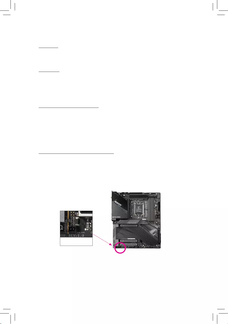
Identifying Your Motherboard Revision
The revision number on your motherboard looks like this: «REV: X.X.» For example, «REV: 1.0″
means the revision of the motherboard is 1.0. Check your motherboard revision before updating
motherboard BIOS, drivers, or when looking for technical information.
Example:

— 3 —
Table of Contents
Chapter 1 Product Introduction ……………………………………………………………………………4
1-1 Motherboard Layout …………………………………………………………………………….. 4
1-2 Motherboard Block Diagram …………………………………………………………………. 6
1-3 Box Contents ………………………………………………………………………………………. 7
Chapter 2 Hardware Installation ………………………………………………………………………….8
2-1 Installation Precautions ………………………………………………………………………… 8
2-2 Product Specications ………………………………………………………………………….. 9
2-3 Installing the CPU and CPU Cooler ……………………………………………………… 13
2-4 Installing the Memory …………………………………………………………………………. 16
2-5 Installing an Expansion Card ………………………………………………………………. 17
2-6 Back Panel Connectors ………………………………………………………………………. 18
2-7 Onboard Buttons and LED ………………………………………………………………….. 20
2-8 Internal Connectors ……………………………………………………………………………. 21
Chapter 3 BIOS Setup ……………………………………………………………………………………..35
Chapter 4 Installing the Operating System and Drivers ………………………………………… 37
4-1 Operating System Installation ……………………………………………………………… 37
4-2 Drivers Installation ……………………………………………………………………………… 38
Chapter 5 Appendix …………………………………………………………………………………………39
5-1 Conguring a RAID Set ………………………………………………………………………. 39
5-2 Debug LED Codes …………………………………………………………………………….. 40
Regulatory Notices ………………………………………………………………………………………. 44
Contact Us …………………………………………………………………………………………………. 48
— 4 —
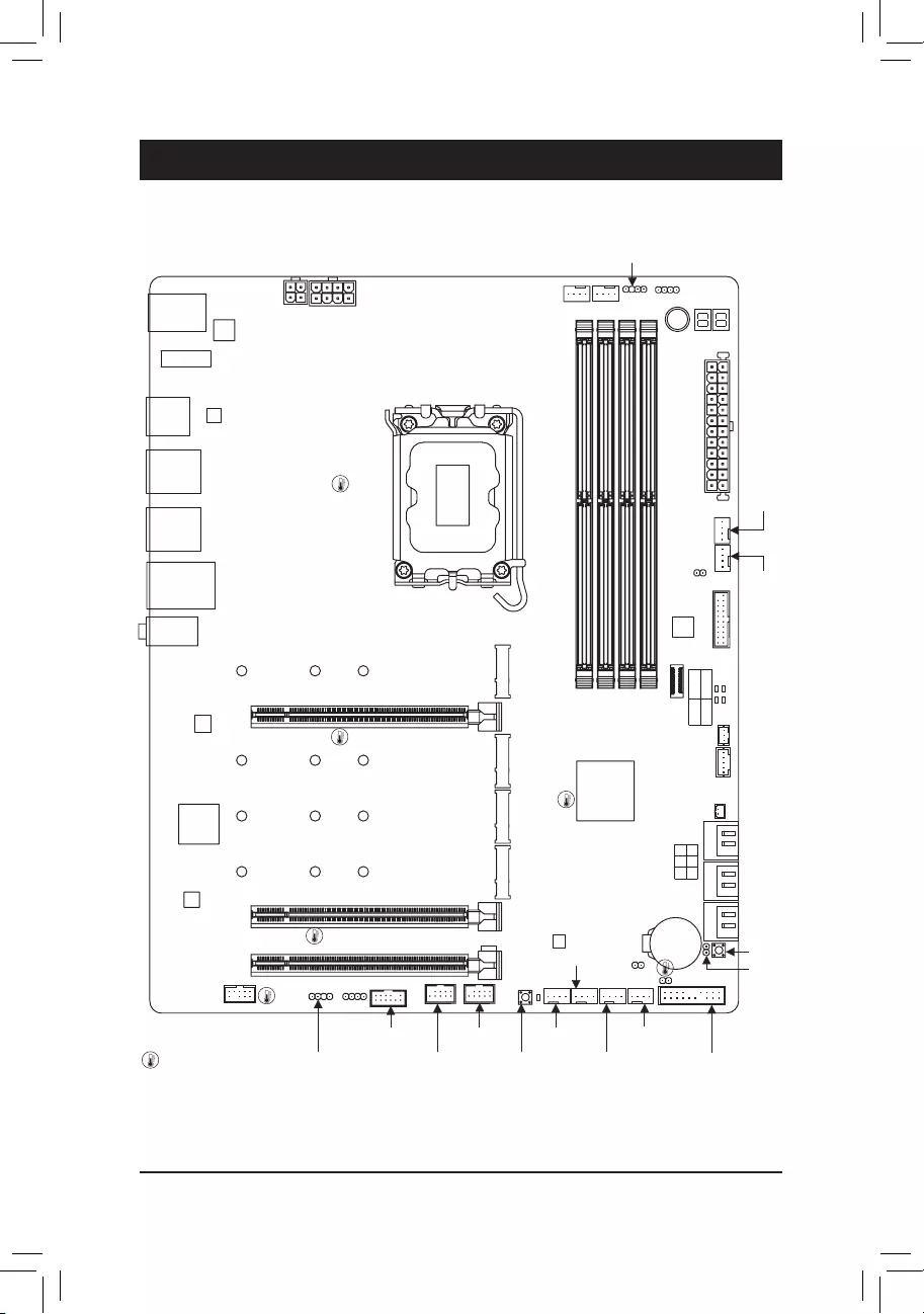
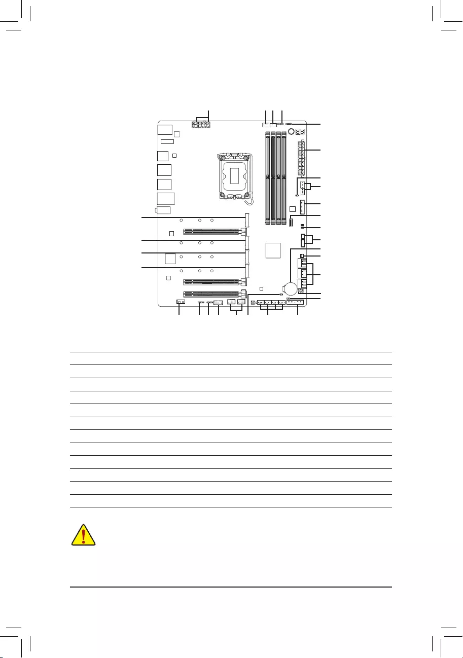
1-1 Motherboard Layout
Chapter 1 Product Introduction
M2_WIFI
R_USB20_1
DP
U32G2
U320G
U32G2_LAN
LGA1700 ATX
AUDIO
DDR5_A1
DDR5_A2
DDR5_B1
DDR5_B2
BAT
Intel® Z690
CLR_CMOS
M_BIOS
THB_C1
THB_C2
CODEC
PCIEX16
PCIEX4_1
PCIEX4_2
F_U320G
F_U32
SYS_FAN6_PUMP
EC_TEMP2
EC_TEMP1
U32
6080110
M2A_CPU
Z690 AORUS PRO
SYS_FAN1
F_USB2D_LED1
F_AUDIO
F_USB1
LED_C1
SYS_FAN3
SPI_TPM
F_PANEL
CPU_FAN
CPU_OPT
SYS_FAN4
iTE®
Super I/O
D_LED2
LED_C2
PW_SW
ATX_12V_2X4ATX_12V_2X2
USB 2.0 Hub
USB 3.2 Gen 1 Hub
USB 2.0 Hub
USB 3.2
Gen 1 Hub
SATA3 357
246 VGA CPU
BOOT DRAM
R_USB20_2
Intel®
2.5GbE LAN
SYS_FAN5_PUMP
NOISE_SENSOR
RST_SW
RST
SYS_FAN2
QFLED
QFLASH_PLUS
6080110
M2C_SB
6080110
M2P_SB
6080110
M2Q_SB
(Note) For debug code information, please refer to Chapter 5.
DB_PORT (Note)
Temperature sensor
— 5 —
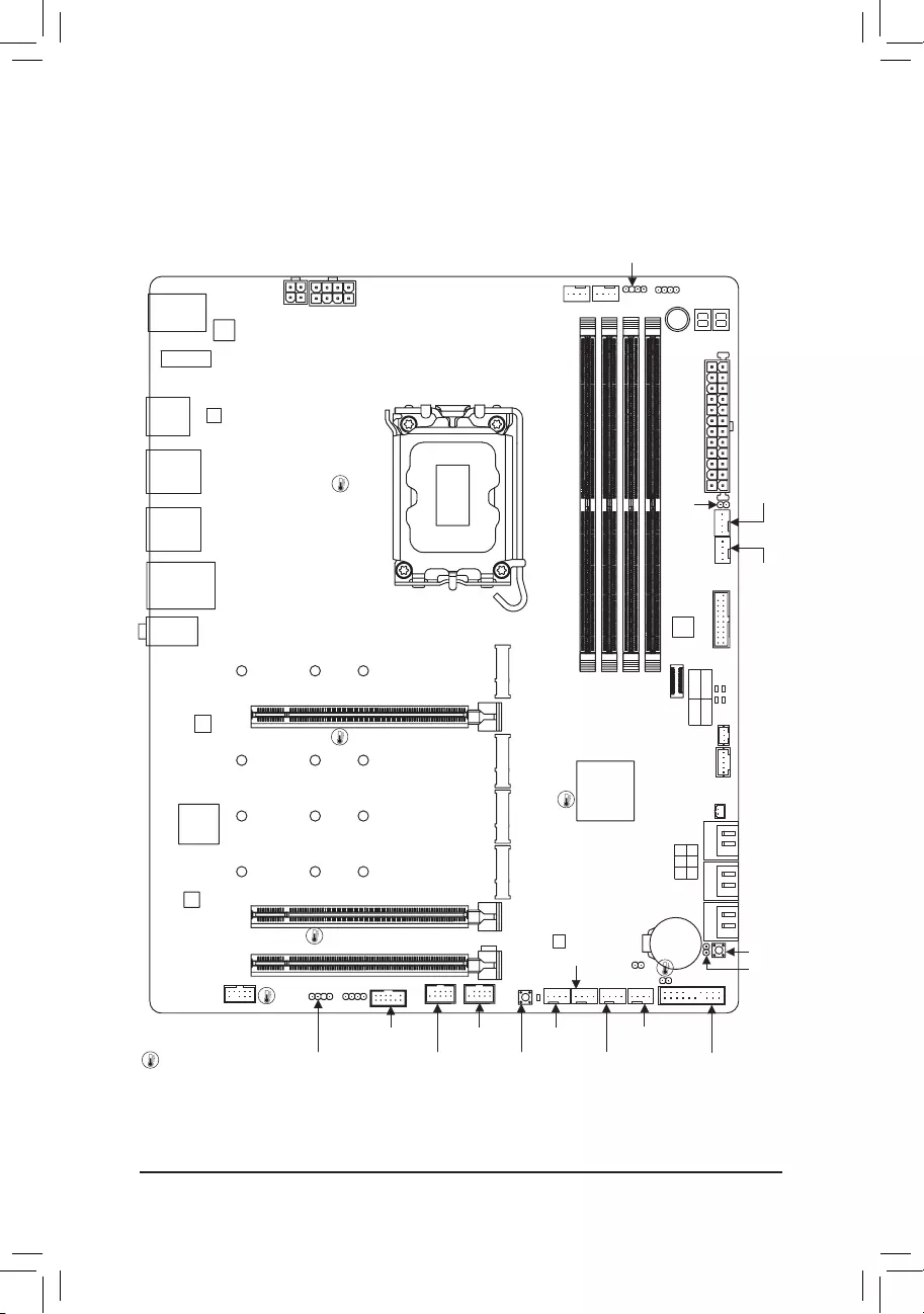
(Note) For debug code information, please refer to Chapter 5.
M2_WIFI
R_USB20_1
DP
U32G2
U320G
U32G2_LAN
LGA1700 ATX
AUDIO
DDR4_A1
DDR4_A2
DDR4_B1
DDR4_B2
BAT
Intel® Z690
CLR_CMOS
M_BIOS
THB_C1
THB_C2
CODEC
PCIEX16
PCIEX4_1
PCIEX4_2
F_U320G
F_U32
SYS_FAN6_PUMP
DB_PORT (Note)
EC_TEMP2
EC_TEMP1
U32
6080110
M2A_CPU
Z690 AORUS PRO DDR4
SYS_FAN1
F_USB2D_LED1
F_AUDIO
F_USB1
LED_C1
SYS_FAN3
SPI_TPM
F_PANEL
CPU_FAN
CPU_OPT
SYS_FAN4
iTE®
Super I/O
D_LED2
LED_C2
PW_SW
ATX_12V_2X4ATX_12V_2X2
USB 2.0 Hub
USB 3.2 Gen 1 Hub
USB 2.0 Hub
USB 3.2
Gen 1 Hub
SATA3 357
246 VGA CPU
BOOT DRAM
R_USB20_2
Temperature sensor
Intel®
2.5GbE LAN
SYS_FAN5_PUMP
NOISE_SENSOR
RST_SW
RST
SYS_FAN2
QFLED
QFLASH_PLUS
6080110
M2C_SB
6080110
M2P_SB
6080110
M2Q_SB
— 6 —
CPU CLK+/- (80~800 MHz)
DMI 4.0
4 SATA 6Gb/s
(SATA3 4~7)
eSPI
Bus
SPI
Bus
DDI
iTE®
Super I/O
6 USB 3.2 Gen 1
8 USB 2.0/1.1
2 USB Type-C®,
with USB 3.2 Gen 2×2 support
4 USB 3.2 Gen 2 Type-A
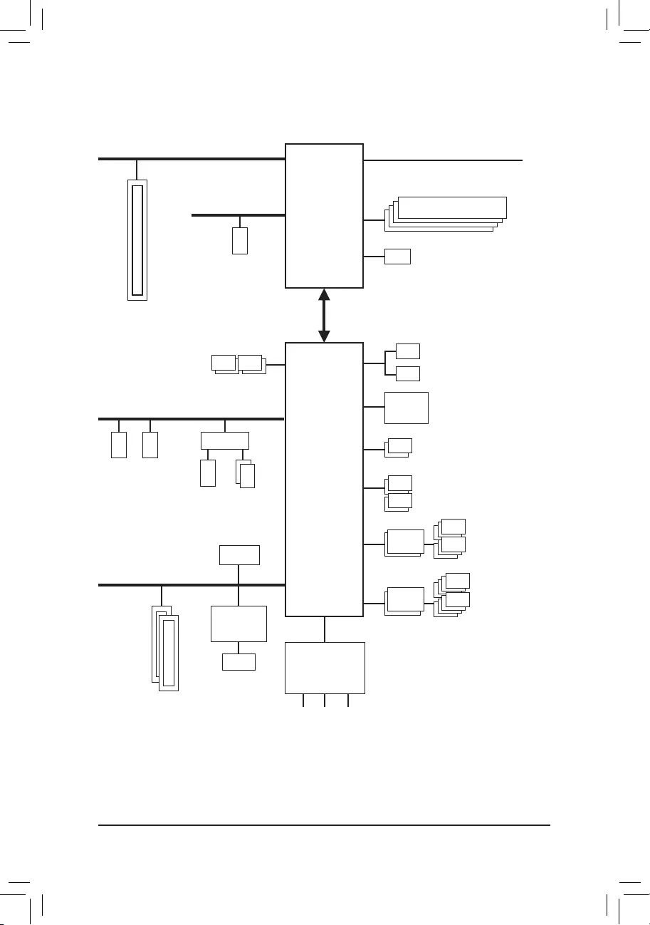
Intel® Z690
DisplayPort
USB 3.2
Gen 1 Hub
BIOS
TPM
PCI Express 5.0 Bus
1-2 Motherboard Block Diagram
1 PCI Express x16
x16
USB 2.0
Hub
Line Out
MIC
S/PDIF Out
CODEC
LGA1700 CPU
1 M.2 Socket 3
(M2C_SB)
2 SATA 6Gb/s
(SATA3 2, 3)
PCI Express 4.0 Bus
2 M.2 Socket 3
(M2P_SB, M2Q_SB)
Switch
or
PCI Express 4.0 Bus
1 M.2 Socket 3
(M2A_CPU)
LAN
RJ45
PCI Express 3.0 Bus
x4 x1
x1
2 PCI Express x4
M.2 WIFI
Intel®
2.5GbE LAN
DDR5 4800/4000 MHzj
DDR4 3200/3000/2933/2666/2400/2133 MHzk
j Only for Z690 AORUS PRO.
k Only for Z690 AORUS PRO DDR4.

— 7 —
1-3 Box Contents
5Z690 AORUS PRO or Z690 AORUS PRO DDR4 motherboard
5User’s Manual
5Quick Installation Guide
5One antenna
5Four SATA cables
5One RGB LED strip extension cable
5One noise detection cable
5Two thermistor cables
5M.2 screws
5One G Connector
* The box contents above are for reference only and the actual items shall depend on the product package you obtain.
The box contents are subject to change without notice.

— 8 —
2-1 Installation Precautions
The motherboard contains numerous delicate electronic circuits and components which can become
damaged as a result of electrostatic discharge (ESD). Prior to installation, carefully read the user’s
manual and follow these procedures:
•Prior to installation, make sure the chassis is suitable for the motherboard.
•Prior to installation, do not remove or break motherboard S/N (Serial Number) sticker or
warranty sticker provided by your dealer. These stickers are required for warranty validation.
•Always remove the AC power by unplugging the power cord from the power outlet before
installing or removing the motherboard or other hardware components.
•When connecting hardware components to the internal connectors on the motherboard, make
sure they are connected tightly and securely.
•When handling the motherboard, avoid touching any metal leads or connectors.
•It is best to wear an electrostatic discharge (ESD) wrist strap when handling electronic
components such as a motherboard, CPU or memory. If you do not have an ESD wrist strap,
keep your hands dry and rst touch a metal object to eliminate static electricity.
•Prior to installing the motherboard, please have it on top of an antistatic pad or within an
electrostatic shielding container.
•Before connecting or unplugging the power supply cable from the motherboard, make sure
the power supply has been turned off.
•Before turning on the power, make sure the power supply voltage has been set according to
the local voltage standard.
•Before using the product, please verify that all cables and power connectors of your hardware
components are connected.
•To prevent damage to the motherboard, do not allow screws to come in contact with the
motherboard circuit or its components.
•Make sure there are no leftover screws or metal components placed on the motherboard or
within the computer casing.
•Do not place the computer system on an uneven surface.
•Do not place the computer system in a high-temperature or wet environment.
•Turning on the computer power during the installation process can lead to damage to system
components as well as physical harm to the user.
•If you are uncertain about any installation steps or have a problem related to the use of the
product, please consult a certied computer technician.
•If you use an adapter, extension power cable, or power strip, ensure to consult with its
installation and/or grounding instructions.
Chapter 2 Hardware Installation
— 9 —
2-2 Product Specications
CPU LGA1700 socket: Support for 12th Generation Intel® Core™ i9 processors/Intel®
Core™ i7 processors/Intel® Core™ i5 processors
(Go to GIGABYTE’s website for the latest CPU support list.)
L3 cache varies with CPU
Chipset Intel® Z690 Express Chipset
Memory Support for DDR5 4800/4000 MHz memory modulesj
Support for DDR4 3200/3000/2933/2666/2400/2133 MHz memory modulesk
4 x DDR DIMM sockets supporting up to 128 GB (32 GB single DIMM capacity)
of system memory
Dual channel memory architecture
Support for ECC Un-buffered DIMM 1Rx8/2Rx8 memory modules (operate in
non-ECC mode)
Support for non-ECC Un-buffered DIMM 1Rx8/2Rx8/1Rx16 memory modules
Support for Extreme Memory Prole (XMP) memory modules
(Go to GIGABYTE’s website for the latest supported memory speeds and memory
modules.)
Onboard
Graphics
Integrated Graphics Processor-Intel® HD Graphics support:
— 1 x DisplayPort, supporting a maximum resolution of 4096×2304@60 Hz
* Support for DisplayPort 1.2 version and HDCP 2.3
(Graphics specications may vary depending on CPU support.)
Audio Realtek® ALC4080 CODEC
High Denition Audio
2-channel analog output
Support for S/PDIF Out
— 7.1-channel digital signals
* Actual output of digital signals may vary depending on the playback content and
software used, and an external DAC is required.
LAN Intel® 2.5GbE LAN chip (2.5 Gbps/1 Gbps/100 Mbps)
Wireless
Communication
Module
Intel® Wi-Fi 6 AX200
— WIFI a, b, g, n, ac, ax, supporting 2.4/5 GHz Dual-Band
— BLUETOOTH 5.2
— Support for 11ax 160MHz wireless standard and up to 2.4 Gbps data rate
* Actual data rate may vary depending on environment and equipment.
Expansion Slots 1 x PCI Express x16 slot, running at x16 (PCIEX16)
(The PCIEX16 slot conforms to PCI Express 5.0 standard.)
2 x PCI Express x16 slots, running at x4 (PCIEX4_1, PCIEX4_2)
(The PCIEX4 slots conform to PCI Express 3.0 standard.)
Multi-Graphics
Technology Support for AMD Quad-GPU CrossFire™ and 2-Way AMD CrossFire™ technologies
j Only for Z690 AORUS PRO.
k Only for Z690 AORUS PRO DDR4.
— 10 —
Storage Interface CPU:
— 1 x M.2 connector (Socket 3, M key, type 2260/2280/22110 PCIe 4.0 x4/x2
SSD support) (M2A_CPU)
Chipset:
— 1 x M.2 connector (Socket 3, M key, type 2260/2280/22110 SATA and PCIe
4.0 x4/x2 SSD support) (M2C_SB)
— 2 x M.2 connectors (Socket 3, M key, type 2260/2280/22110 PCIe 4.0 x4/x2
SSD support) (M2P_SB/M2Q_SB)
— 6 x SATA 6Gb/s connectors
Support for RAID 0, RAID 1, RAID 5, and RAID 10
* Refer to «2-8 Internal Connectors,» for the installation notices for the M.2 and SATA
connectors.
Intel® Optane™ Memory Ready
* System acceleration with Intel® Optane™ Memory can only be enabled on the M.2
connectors supported by the Chipset.
USB Chipset:
— 2 x USB Type-C® ports, with USB 3.2 Gen 2×2 support (1 port on the back
panel, 1 port available through the internal USB header)
— 4 x USB 3.2 Gen 2 Type-A ports (red) on the back panel
Chipset+2 USB 3.2 Gen 1 Hubs:
— 6 x USB 3.2 Gen 1 ports (4 ports on the back panel, 2 ports available through
the internal USB header)
Chipset+2 USB 2.0 Hubs:
— 8 x USB 2.0/1.1 ports (4 ports on the back panel, 4 ports available through
the internal USB headers)
Internal
Connectors
1 x 24-pin ATX main power connector
1 x 8-pin ATX 12V power connector
1 x 4-pin ATX 12V power connector
1 x CPU fan header
1 x water cooling CPU fan header
4 x system fan headers
2 x system fan/water cooling pump headers
2 x addressable LED strip headers
2 x RGB LED strip headers
4 x M.2 Socket 3 connectors
6 x SATA 6Gb/s connectors
1 x front panel header
1 x front panel audio header
1 x USB Type-C® header, with USB 3.2 Gen 2×2 support
1 x USB 3.2 Gen 1 header
2 x USB 2.0/1.1 headers
1 x noise detection header
2 x Thunderbolt™ add-in card connectors
1 x Trusted Platform Module header (For the GC-TPM2.0 SPI/GC-TPM2.0 SPI
2.0 module only)
— 11 —
Internal
Connectors
1 x power button
1 x reset button
1 x Q-Flash Plus button
2 x temperature sensor headers
1 x reset jumper
1 x Clear CMOS jumper
Back Panel
Connectors
1 x USB Type-C® port, with USB 3.2 Gen 2×2 support
4 x USB 3.2 Gen 2 Type-A ports (red)
4 x USB 3.2 Gen 1 ports
4 x USB 2.0/1.1 ports
2 x SMA antenna connectors (2T2R)
1 x DisplayPort
1 x RJ-45 port
1 x optical S/PDIF Out connector
2 x audio jacks
I/O Controller iTE® I/O Controller Chip
Hardware
Monitor
Voltage detection
Temperature detection
Fan speed detection
Water cooling ow rate detection
Fan fail warning
Fan speed control
* Whether the fan (pump) speed control function is supported will depend on the fan
(pump) you install.
Noise detection
BIOS 1 x 256 Mbit ash
Use of licensed AMI UEFI BIOS
PnP 1.0a, DMI 2.7, WfM 2.0, SM BIOS 2.7, ACPI 5.0
Unique Features Support for APP Center
* Available applications in APP Center may vary by motherboard model. Supported
functions of each application may also vary depending on motherboard specications.
— @BIOS
— EasyTune
— Fast Boot
— Game Boost
— ON/OFF Charge
— RGB Fusion
— Smart Backup
— System Information Viewer
Support for Q-Flash Plus
Support for Q-Flash
Support for Xpress Install
— 12 —
Please visit GIGABYTE’s website for support lists of CPU, memory
modules, SSDs, and M.2 devices.
Please visit the Support\Utility List page on GIGABYTE’s website to download the latest
version of apps.
Bundled
Software
Norton® Internet Security (OEM version)
cFosSpeed
Operating
System Support for Windows 10 64-bit
Form Factor ATX Form Factor; 30.5cm x 24.4cm
* GIGABYTE reserves the right to make any changes to the product specications and product-related information without
prior notice.
Z690 AORUS
PRO
Z690 AORUS
PRO DDR4
— 13 —
2-3 Installing the CPU and CPU Cooler
Read the following guidelines before you begin to install the CPU:
•Make sure that the motherboard supports the CPU.
(Go to GIGABYTE’s website for the latest CPU support list.)
•Always turn off the computer and unplug the power cord from the power outlet before installing the
CPU to prevent hardware damage.
•Locate the pin one of the CPU. The CPU cannot be inserted if oriented incorrectly. (Or you may
locate the notches on both sides of the CPU and alignment keys on the CPU socket.)
•Apply an even and thin layer of thermal grease on the surface of the CPU.
•Do not turn on the computer if the CPU cooler is not installed, otherwise overheating and damage
of the CPU may occur.
•Set the CPU host frequency in accordance with the CPU specications. It is not recommended
that the system bus frequency be set beyond hardware specications since it does not meet the
standard requirements for the peripherals. If you wish to set the frequency beyond the standard
specications, please do so according to your hardware specications including the CPU, graphics
card, memory, hard drive, etc.
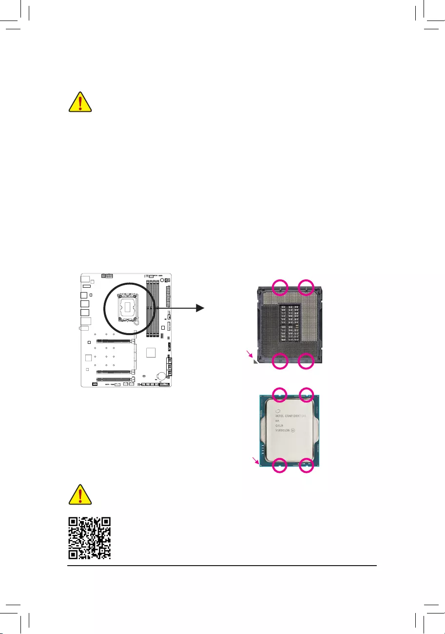
A. Note the CPU Orientation
Note the alignment keys on the motherboard CPU socket and the notches on the CPU.
Please visit GIGABYTE’s website for details on hardware installation.
Do not remove the CPU socket cover before inserting the CPU. It may pop off from the load
plate automatically after you insert the CPU and close the load plate.
Notch
Notch
LGA1700 CPU
Triangle Pin One Marking
on the CPU
Alignment Key
LGA1700 CPU Socket
Triangle Pin One Marking
of the CPU Socket
Alignment Key
— 14 —
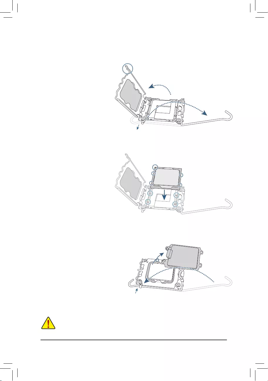
Do not force to engage the CPU socket locking lever when the CPU is not installed correctly
as this would damage the CPU and CPU socket.
B. Installing the CPU
Follow the steps below to correctly install the CPU into the motherboard CPU socket.
w
u
v
jGently press the CPU socket lever handle
down and away from the socket.
kCompletely lift up the CPU socket lock—
ing lever.
lUse the finger tab on the side of the
metal load plate to lift open the metal
load plate with the plastic protective cover
attached to it.
Hold the CPU with your ngers by the edges.
Align the CPU pin one marking (triangle) with
the pin one corner of the CPU socket (or you
may align the CPU notches with the socket
alignment keys) and gently insert the CPU
into position.
Make sure the CPU is properly installed and
then close the load plate. The plastic protec-
tive cover will pop off, just remove it. Secure
the lever under its retention tab to complete
the installation of the CPU.
* Always replace the plastic protective cover
when the CPU is not installed to protect the
CPU socket.
j
k
l
Finger Tab
Pin One
j
k
l
— 15 —
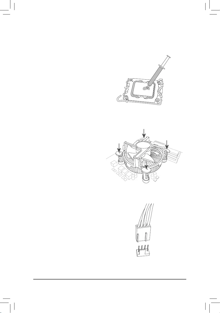
C. Installing the CPU Cooler
Be sure to install the CPU cooler after installing the CPU. (Actual installation process may differ depending the
CPU cooler to be used. Refer to the user’s manual for your CPU cooler.)
u
v
Apply an even and thin layer of thermal
grease on the surface of the installed CPU.
Place the cooler atop the CPU, aligning the
four push pins through the pin holes on the
motherboard. Push down on the push pins
diagonally.
j
j
kk
w
Finally, attach the power connector of
the CPU cooler to the CPU fan header
(CPU_FAN) on the motherboard.
CPU_FAN
— 16 —
2-4 Installing the Memory
Read the following guidelines before you begin to install the memory:
•Make sure that the motherboard supports the memory. It is recommended that memory of the same
capacity, brand, speed, and chips be used. (Go to GIGABYTE’s website for the latest supported
memory speeds and memory modules.)
•Always turn off the computer and unplug the power cord from the power outlet before installing the
memory to prevent hardware damage.
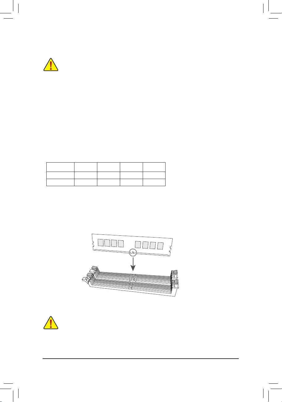
•Memory modules have a foolproof design. A memory module can be installed in only one direction.
If you are unable to insert the memory, switch the direction.
Dual Channel Memory Conguration
This motherboard provides four memory sockets and supports Dual Channel Technology. After the memory
is installed, the BIOS will automatically detect the specications and capacity of the memory. Enabling Dual
Channel memory mode will double the original memory bandwidth.
The four memory sockets are divided into two channels and each channel has two memory sockets as following:
Channel A: DDR5_A1j/DDR4_A1k, DDR5_A2j/DDR4_A2k
Channel B: DDR5_B1j/DDR4_B1k, DDR5_B2j/DDR4_B2k
* Recommanded Dual Channel Memory Conguration:
DDR5_A1j
DDR4_A1k
DDR5_A2j
DDR4_A2k
DDR5_B1j
DDR4_B1k
DDR5_B2j
DDR4_B2k
2 Modules — — DS/SS — — DS/SS
4 Modules DS/SS DS/SS DS/SS DS/SS
(SS=Single-Sided, DS=Double-Sided, «- -«=No Memory)
Due to CPU limitations, read the following guidelines before installing the memory in Dual Channel mode.
1. Dual Channel mode cannot be enabled if only one memory module is installed.
2. When enabling Dual Channel mode with two or four memory modules, it is recommended that memory of
the same capacity, brand, speed, and chips be used.
When installing a single memory module, we recommend that you install it in the DDR5_A2j/
DDR4_A2k socket.
j Only for Z690 AORUS PRO.
k Only for Z690 AORUS PRO DDR4.
DDR5_A1j/DDR4_A1k
DDR5_A2j/DDR4_A2k
DDR5_B1j/DDR4_B1k
DDR5_B2j/DDR4_B2k
— 17 —
2-5 Installing an Expansion Card
Read the following guidelines before you begin to install an expansion card:
•Make sure the motherboard supports the expansion card. Carefully read the manual that came
with your expansion card.
•Always turn off the computer and unplug the power cord from the power outlet before installing an
expansion card to prevent hardware damage.
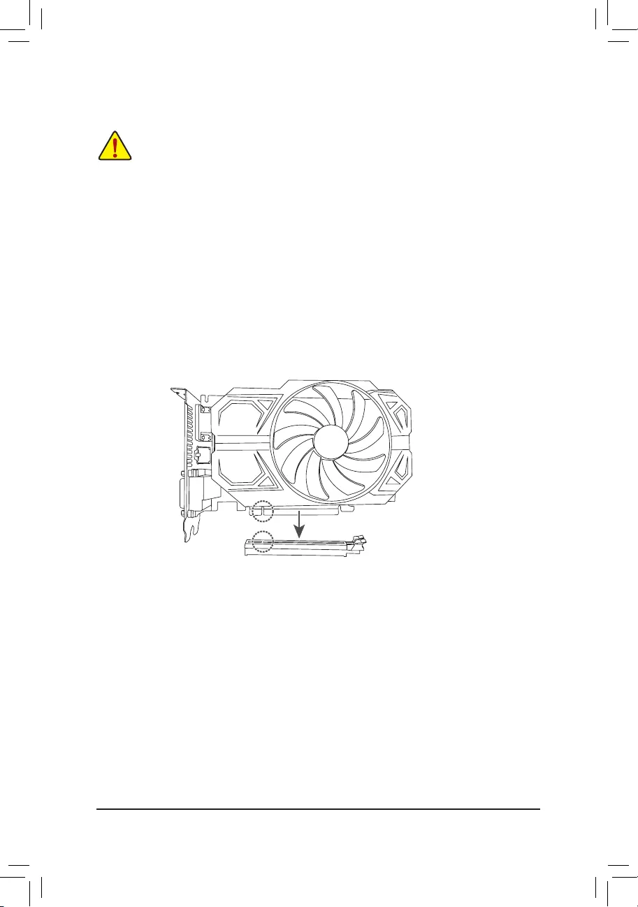
Follow the steps below to correctly install your expansion card in the expansion slot.
1. Locate an expansion slot that supports your card. Remove the metal slot cover from the chassis back panel.
2. Align the card with the slot, and press down on the card until it is fully seated in the slot.
3. Make sure the metal contacts on the card are completely inserted into the slot.
4. Secure the card’s metal bracket to the chassis back panel with a screw.
5. After installing all expansion cards, replace the chassis cover(s).
6. Turn on your computer. If necessary, go to BIOS Setup to make any required BIOS changes for your
expansion card(s).
7. Install the driver provided with the expansion card in your operating system.
PCIEX16 Slot
— 18 —
2-6 Back Panel Connectors
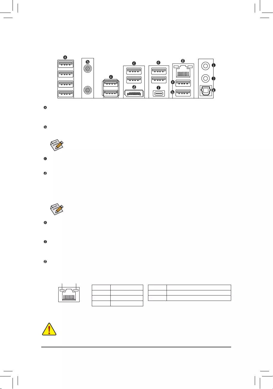
USB 3.2 Gen 1 Port
The USB 3.2 Gen 1 port supports the USB 3.2 Gen 1 specication and is compatible to the USB 2.0
specication. Use this port for USB devices.
SMA Antenna Connectors (2T2R)
Use this connector to connect an antenna.
USB 2.0/1.1 Port
The USB port supports the USB 2.0/1.1 specication. Use this port for USB devices.
DisplayPort
DisplayPort delivers high quality digital imaging and audio, supporting bi-directional audio transmission.
DisplayPort can support HDCP 2.3 content protection mechanisms. You can use this port to connect your
DisplayPort-supported monitor. Note: The DisplayPort Technology can support a maximum resolution of
4096×2304@60 Hz but the actual resolutions supported depend on the monitor being used.
USB 3.2 Gen 2 Type-A Port (Red)
The USB 3.2 Gen 2 port supports the USB 3.2 Gen 2 specication and is compatible to the USB 3.2 Gen 1
and USB 2.0 specication. Use this port for USB devices.
USB Type-C® Port
The reversible USB port supports the USB 3.2 Gen 2×2 specication and is compatible to the USB 3.2
Gen 2, USB 3.2 Gen 1, and USB 2.0 specications. Use this port for USB devices.
RJ-45 LAN Port
The Gigabit Ethernet LAN port provides Internet connection at up to 2.5 Gbps data rate. The following
describes the states of the LAN port LEDs.
Tighten the antennas to the antenna connectors and then aim the antennas correctly for better
signal reception.
After installing the DisplayPort device, make sure to set the default sound playback device to
DisplayPort. (The item name may differ depending on your operating system.)
Activity LEDSpeed LED
LAN Port
Speed LED:
State Description
Green 2.5 Gbps data rate
Orange 1 Gbps data rate
Off 100 Mbps data rate
Activity LED:
State Description
Blinking Data transmission or receiving is occurring
On No data transmission or receiving is occurring
•When removing the cable connected to a back panel connector, rst remove the cable from your
device and then remove it from the motherboard.
•When removing the cable, pull it straight out from the connector. Do not rock it side to side to
prevent an electrical short inside the cable connector.
— 19 —
USB 3.2 Gen 2 Type-A Port (Red) (Q-Flash Plus Port)
The USB 3.2 Gen 2 port supports the USB 3.2 Gen 2 specication and is compatible to the USB 3.2 Gen 1
and USB 2.0 specication. Use this port for USB devices. Before using Q-Flash Plus (Note), make sure to insert
the USB ash drive into this port rst.
Line Out
The line out jack.
Mic In
The Mic in jack.
Optical S/PDIF Out Connector
This connector provides digital audio out to an external audio system that supports digital optical audio.
Before using this feature, ensure that your audio system provides an optical digital audio in connector.
Please visit GIGABYTE’s website for details on conguring the audio software.
(Note) To enable the Q-Flash Plus function, please navigate to the «Unique Features» page of GIGABYTE’s
website for more information.
— 20 —
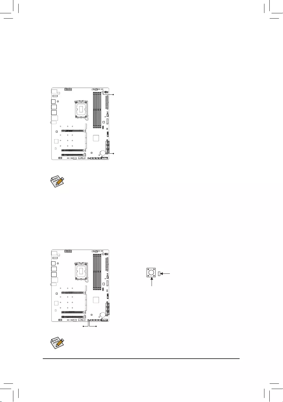
2-7 Onboard Buttons and LED
QFLASH_PLUS (Q-Flash Plus Button)
Q-Flash Plus allows you to update the BIOS when your system is off (S5 shutdown state). Save the latest BIOS
on a USB thumb drive and plug it into the dedicated port, and then you can now ash the BIOS automatically by
simply pressing the Q-Flash Plus button. The QFLED will ash when the BIOS matching and ashing activities
start and will stop ashing when the main BIOS ashing is complete.
Quick Buttons
This motherboard has 2 quick buttons: power button and reset button. The power button and reset button allow
users to quickly turn on/off or reset the computer in an open-case environment when they want to change
hardware components or conduct hardware testing.
PW_SW: Power Button
RST_SW: Reset Button
RST_SW
PW_SW
The reset button provides you with several functions to use. To remap the button to perform different
tasks, please navigate to the «BIOS Setup» page of GIGABYTE’s website and search for «RST_SW
(MULTIKEY)» for more information.
QFLEDQFLASH_PLUS
To enable the Q-Flash Plus function, please navigate to the «Unique Features» page of GIGABYTE’s
website for more information.
QFLASH_PLUS
QFLED
— 21 —
2-8 Internal Connectors
Read the following guidelines before connecting external devices:
•First make sure your devices are compliant with the connectors you wish to connect.
•Before installing the devices, be sure to turn off the devices and your computer. Unplug the power
cord from the power outlet to prevent damage to the devices.
•After installing the device and before turning on the computer, make sure the device cable has
been securely attached to the connector on the motherboard.
1) ATX_12V_2X2/ATX_12V_2X4
2) ATX
3) CPU_FAN
4) SYS_FAN1/2/3/4
5) SYS_FAN5/6_PUMP
6) CPU_OPT
7) EC_TEMP1/EC_TEMP2
 LED_C1/LED_C2
9) D_LED1/D_LED2
10) M2A_CPU/M2C_SB/M2P_SB/M2Q_SB
11) SATA3 2/3/4/5/6/7
12) BAT
13) F_PANEL
14) F_AUDIO
15) F_U320G
16) F_U32
17) F_USB1/F_USB2
18) SPI_TPM
19) THB_C1/THB_C2
20) NOISE_SENSOR
21) CLR_CMOS
22) RST
23) CPU/DRAM/VGA/BOOT
137
16
15
2
8
19
11
5
17 414 18
91
9 8
21
22
36
12
20
10
10
10
10
23
7
— 22 —
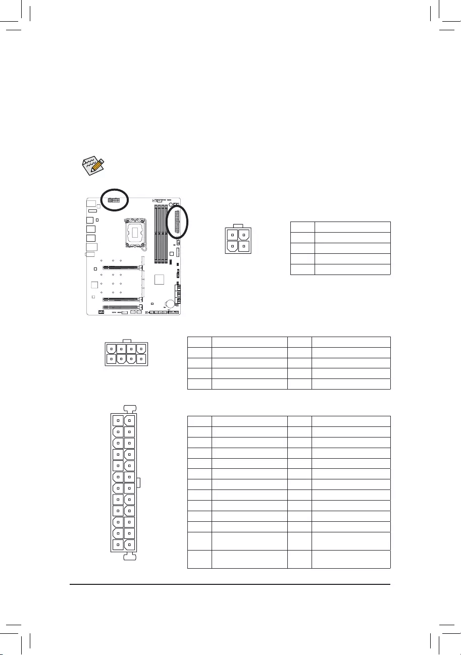
1/2) ATX_12V_2X2/ATX_12V_2X4/ATX (2×2, 2×4, 12V Power Connectors and 2×12 Main
Power Connector)
With the use of the power connector, the power supply can supply enough stable power to all the components
on the motherboard. Before connecting the power connector, rst make sure the power supply is turned
off and all devices are properly installed. The power connector possesses a foolproof design. Connect the
power supply cable to the power connector in the correct orientation.
The 12V power connector mainly supplies power to the CPU. If the 12V power connector is not connected,
the computer will not start.
To meet expansion requirements, it is recommended that a power supply that can withstand high
power consumption be used (500W or greater). If a power supply is used that does not provide the
required power, the result can lead to an unstable or unbootable system.
ATX_12V_2X4
ATX:
Pin No. Denition Pin No. Denition
1 3.3V 13 3.3V
2 3.3V 14 -12V
3 GND 15 GND
4 +5V 16 PS_ON (soft On/Off)
5 GND 17 GND
6 +5V 18 GND
7 GND 19 GND
8 Power Good 20 NC
9 5VSB (stand by +5V) 21 +5V
10 +12V 22 +5V
11 +12V (Only for 2×12-pin
ATX)
23 +5V (Only for 2×12-pin ATX)
12 3.3V (Only for 2×12-pin
ATX)
24 GND (Only for 2×12-pin ATX)
41
8
5
131
2412
ATX
ATX_12V_2X2
21
3 4
ATX_12V_2X4:
Pin No. Denition Pin No. Denition
1GND (Only for 2×4-pin 12V) 5 +12V (Only for 2×4-pin 12V)
2GND (Only for 2×4-pin 12V) 6 +12V (Only for 2×4-pin 12V)
3 GND 7 +12V
4 GND 8 +12V
ATX_12V_2X2:
Pin No. Denition
1 GND
2 GND
3 +12V
4 +12V
— 23 —
•Be sure to connect fan cables to the fan headers to prevent your CPU and system from
overheating. Overheating may result in damage to the CPU or the system may hang.
•These fan headers are not conguration jumper blocks. Do not place a jumper cap on the headers.
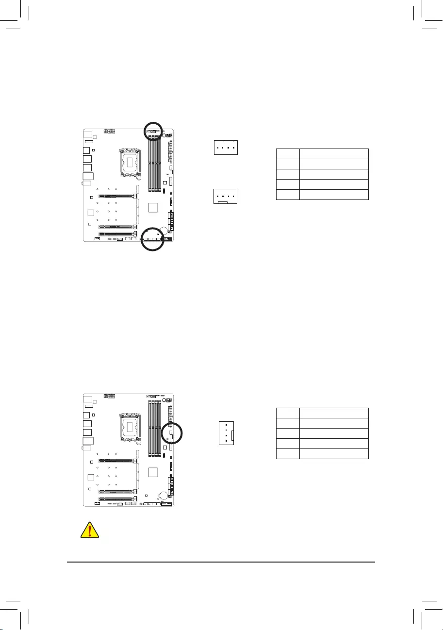
3/4) CPU_FAN/SYS_FAN1/2/3/4 (Fan Headers)
All fan headers on this motherboard are 4-pin. Most fan headers possess a foolproof insertion design.
When connecting a fan cable, be sure to connect it in the correct orientation (the black connector wire is
the ground wire). The speed control function requires the use of a fan with fan speed control design. For
optimum heat dissipation, it is recommended that a system fan be installed inside the chassis.
CPU_FAN
1
1
SYS_FAN1/SYS_FAN2/
SYS_FAN3/SYS_FAN4
Pin No. Denition
1 GND
2 Voltage Speed Control
3 Sense
4 PWM Speed Control
5) SYS_FAN5/6_PUMP (System Fan/Water Cooling Pump Headers)
The fan/pump headers are 4-pin. Most fan headers possess a foolproof insertion design. When connecting
a fan cable, be sure to connect it in the correct orientation (the black connector wire is the ground wire).
The speed control function requires the use of a fan with fan speed control design. For optimum heat
dissipation, it is recommended that a system fan be installed inside the chassis. The header also provides
speed control for a water cooling pump. Please navigate to the «BIOS Setup» page of GIGABYTE’s website
and search for «Smart Fan 6» for more information.
Pin No. Denition
1 GND
2 Voltage Speed Control
3 Sense
4 PWM Speed Control
1
— 24 —
7) EC_TEMP1/EC_TEMP2 (Temperature Sensor Headers)
Connect the thermistor cables to the headers for temperature detection.
Pin No. Denition
1 SENSOR IN
2 GND
EC_TEMP1
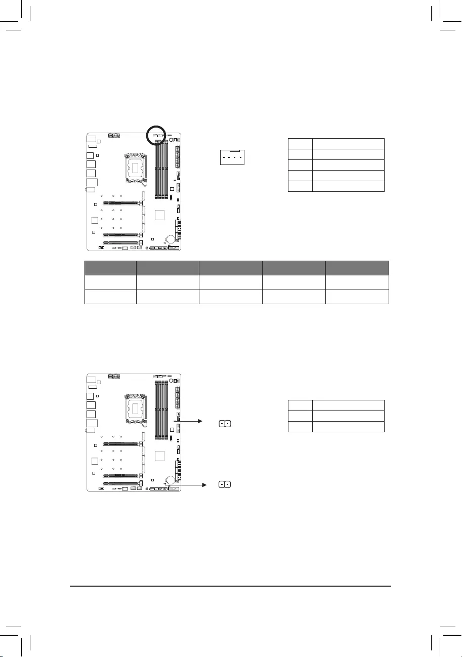
6) CPU_OPT (Water Cooling CPU Fan Header)
The fan header is 4-pin and possesses a foolproof insertion design. Most fan headers possess a foolproof
insertion design. When connecting a fan cable, be sure to connect it in the correct orientation (the black
connector wire is the ground wire). The speed control function requires the use of a fan with fan speed
control design.
1
Pin No. Denition
1 GND
2 Voltage Speed Control
3 Sense
4 PWM Speed Control
1
Connector CPU_FAN SYS_FAN1~4 SYS_FAN5/6_PUMP CPU_OPT
Maximum Current 2A 2A 2A 2A
Maximum Power 24W 24W 24W 24W
1
EC_TEMP2
— 25 —
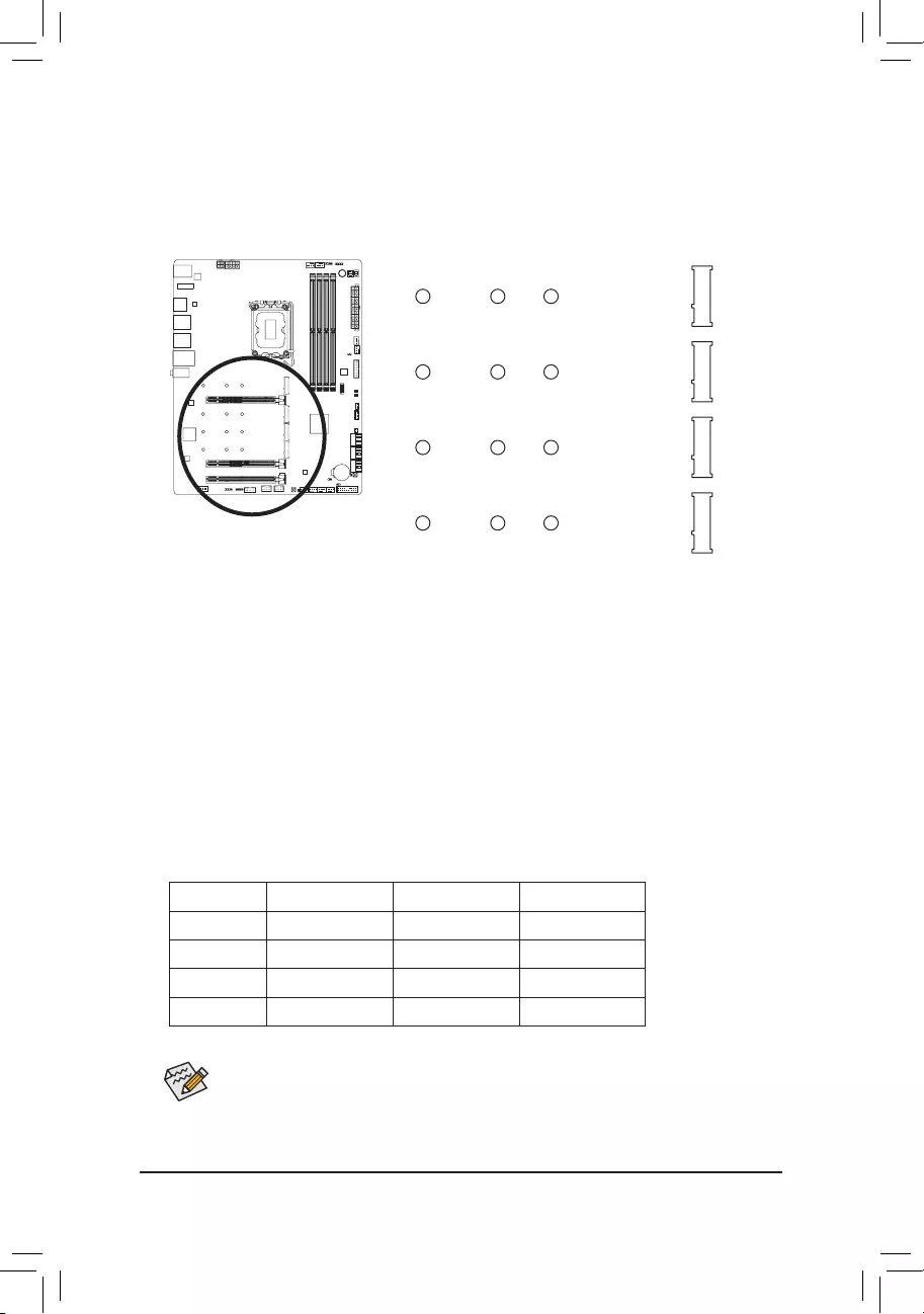
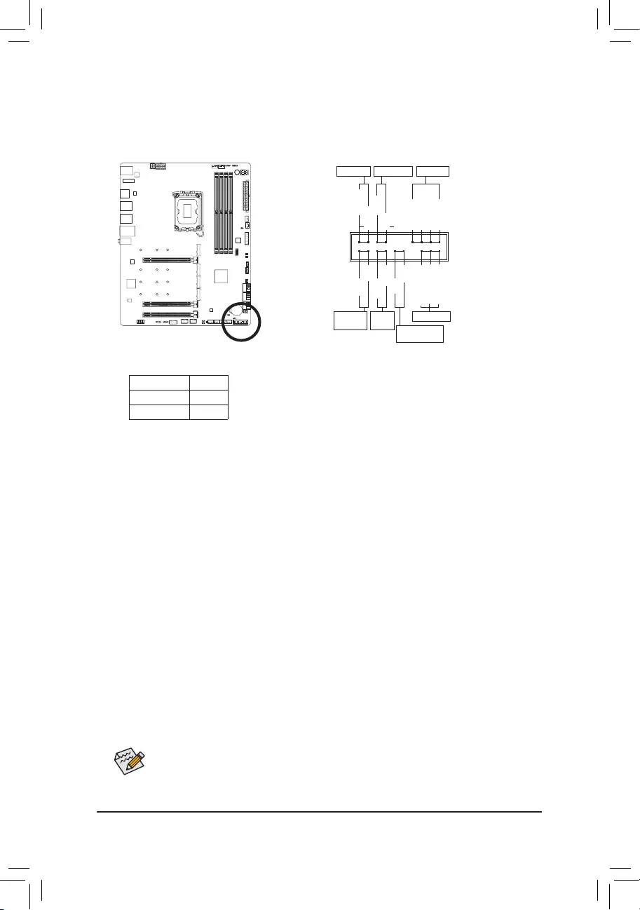
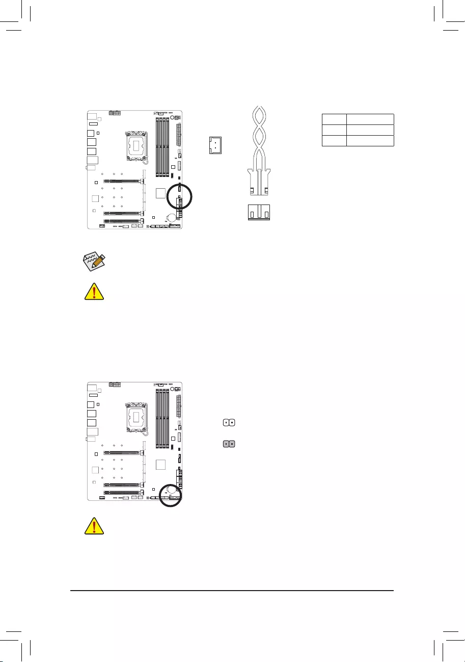
9) D_LED1/D_LED2 (Addressable LED Strip Headers)
The headers can be used to connect a standard 5050 addressable LED strip, with maximum power rating
of 5A (5V) and maximum number of 1000 LEDs.
Before installing the devices, be sure to turn off the devices and your computer. Unplug the power
cord from the power outlet to prevent damage to the devices.
For how to turn on/off the lights of the LED strip, please navigate to the «Unique Features» page
of GIGABYTE’s website.
1
D_LED1
Pin No. Denition
1 V (5V)
2 Data
3 No Pin
4 GND
Connect your addressable LED strip to the header. The power pin (marked
with a triangle on the plug) of the LED strip must be connected to Pin 1 of
the addressable LED strip header. Incorrect connection may lead to the
damage of the LED strip.
1
D_LED2
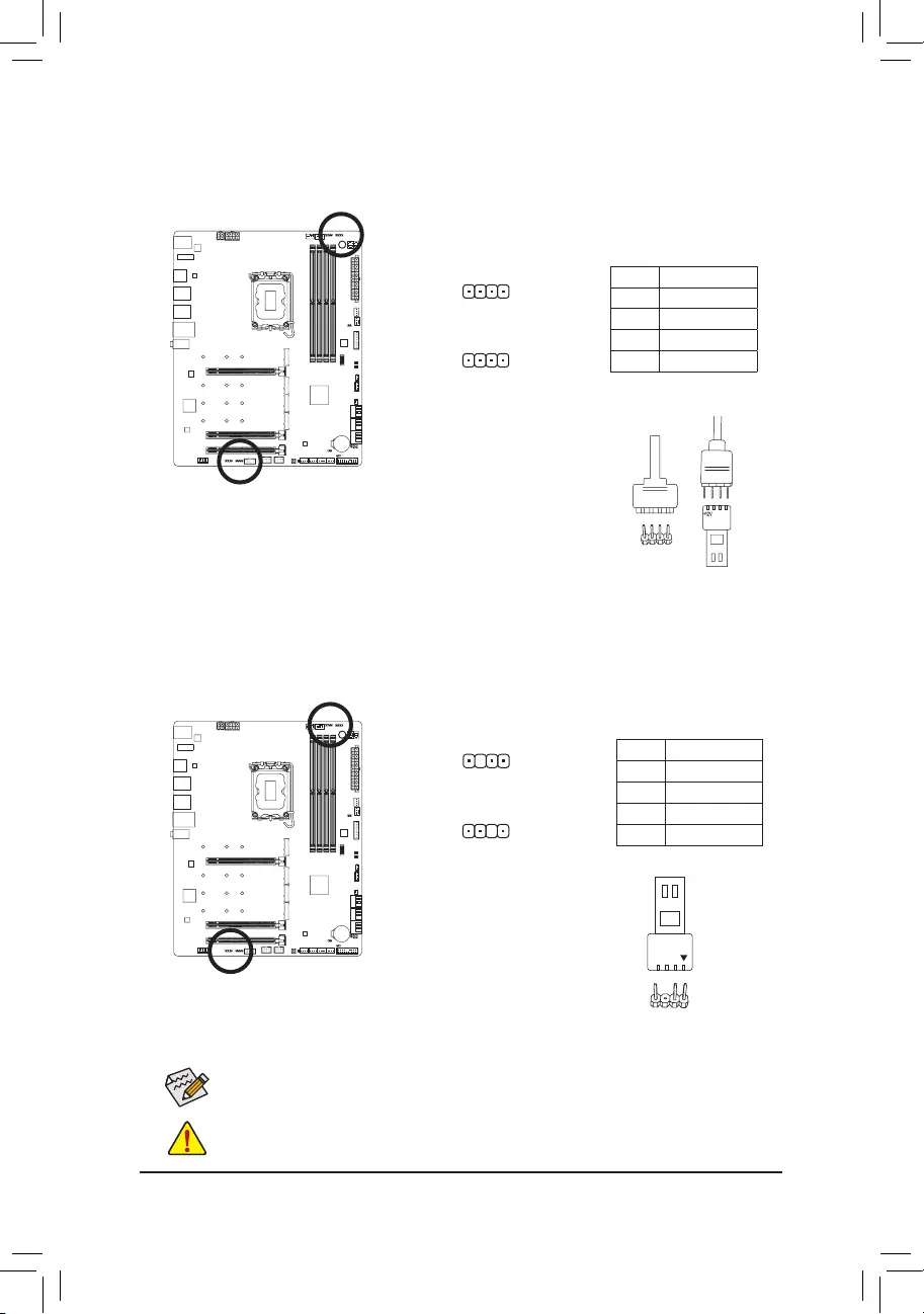
LED_C1/LED_C2 (RGB LED Strip Headers)
The headers can be used to connect a standard 5050 RGB LED strip (12V/G/R/B), with maximum power
rating of 2A (12V) and maximum length of 2m.
Connect one end of the RGB LED strip extension cable to the header and
the other end to your RGB LED strip. The black wire (marked with a triangle
on the plug) of the extension cable must be connected to Pin 1 (12V) of
this header. The 12V pin (marked with an arrow) on the other end of the
extension cable must be lined up with the 12V of the LED strip. Be careful
with the connection orientation of the LED strip; incorrect connection may
lead to the damage of the LED strip.
12VRGB
12V
1
RGB LED
Strip
BG12VR
Pin No. Denition
1 12V
2 G
3 R
4 B
1
LED_C2
1
LED_C1
Addressable LED
Strip
1
F_USB30 F_U
B_
F_ F_
_
B
BS_
B
SB_
B
_S
S_
_
B
_U
_
B
S
123
123
123
123
1
1
1
1
BSS
S
_S
SSU
1 2 3
S3 BSSS
U
__ 3
F_USB3F
S _
S _
S _
SF
B_
B_
F
_0
S
S
_0F
_F
_
_
__B
U
S _S
_ SF_
B
USB0_B
B_
B_
F_USB3
F_USB303
_
_3U
S_
_S
SS_F
_
F_USB30 F_U
B_
F_ F_
_
B
BS_
B
SB_
B
_S
S_
_
B
_U
_
B
S
123
123
123
123
1
1
1
1
BSS
S
_S
SSU
1 2 3
S3 BSSS
U
__ 3
F_USB3F
S _
S _
S _
SF
B_
B_
F
_0
S
S
_0F
_F
_
_
__B
U
S _S
_ SF_
B
USB0_B
B_
B_
F_USB3
F_USB303
_
_3U
S_
_S
SS_F
_
— 26 —
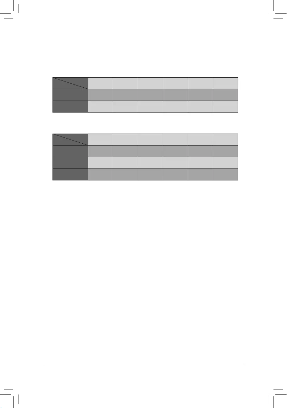
10) M2A_CPU/M2C_SB/M2P_SB/M2Q_SB (M.2 Socket 3 Connectors)
There are two types of M.2 SSDs: M.2 SATA SSDs and M.2 PCIe SSDs. Be sure to verify which type of
M.2 SSDs is supported by the M.2 socket you want to use. Please note that an M.2 PCIe SSD cannot
be used to create a RAID set either with an M.2 SATA SSD or a SATA hard drive. Please navigate to the
«Conguring a RAID Set» page of GIGABYTE’s website for instructions on conguring a RAID array.
M2A_CPU
M2P_SB
M2Q_SB
Follow the steps below to correctly install an M.2 SSD in the M.2 connector.
Step 1:
Locate the M.2 connector where you will install the M.2 SSD, use a screwdriver to unfasten the screw on
the heatsink and then remove the heatsink. Remove the protective lm from the thermal pad on the M.2
connector.
Step 2:
Locate the proper mounting hole based on the length of your M.2 SSD drive. If needed, move the standoff
to the desired mounting hole. Insert the M.2 SSD into the M.2 connector at an angle.
Step 3:
Press the M.2 SSD down and then use the included screw to secure it in the connector. Remove the
protective lm from the bottom of the heatsink. Then replace the heatsink and secure it to the original hole.
F_USB30 F_U
B_
F_ F_
_
B
BS_
B
SB_
B
_S
S_
_
B
_U
_
B
S
123
123
123
123
1
1
1
1
BSS
S
_S
SSU
1 2 3
S3 BSSS
U
__ 3
F_USB3F
S _
S _
S _
SF
B_
B_
F
_0
S
S
_0F
_F
_
_
__B
U
S _S
_ SF_
B
USB0_B
B_
B_
F_USB3
F_USB303
_
_3U
S_
_S
SS_F
_
80110 60
F_USB30 F_U
B_
F_ F_
_
B
BS_
B
SB_
B
_S
S_
_
B
_U
_
B
S
123
123
123
123
1
1
1
1
BSS
S
_S
SSU
1 2 3
S3 BSSS
U
__ 3
F_USB3F
S _
S _
S _
SF
B_
B_
F
_0
S
S
_0F
_F
_
_
__B
U
S _S
_ SF_
B
USB0_B
B_
B_
F_USB3
F_USB303
_
_3U
S_
_S
SS_F
_
80110 60
F_USB30 F_U
B_
F_ F_
_
B
BS_
B
SB_
B
_S
S_
_
B
_U
_
B
S
123
123
123
123
1
1
1
1
BSS
S
_S
SSU
1 2 3
S3 BSSS
U
__ 3
F_USB3F
S _
S _
S _
SF
B_
B_
F
_0
S
S
_0F
_F
_
_
__B
U
S _S
_ SF_
B
USB0_B
B_
B_
F_USB3
F_USB303
_
_3U
S_
_S
SS_F
_
80110 60
F_USB30 F_U
B_
F_ F_
_
B
BS_
B
SB_
B
_S
S_
_
B
_U
_
B
S
123
123
123
123
1
1
1
1
BSS
S
_S
SSU
1 2 3
S3 BSSS
U
__ 3
F_USB3F
S _
S _
S _
SF
B_
B_
F
_0
S
S
_0F
_F
_
_
__B
U
S _S
_ SF_
B
USB0_B
B_
B_
F_USB3
F_USB303
_
_3U
S_
_S
SS_F
_
80110 60
M2C_SB
* Types of M.2 SSDs supported by each M.2 connector:
M.2 PCIe x4 SSD M.2 PCIe x2 SSD M.2 SATA SSD
M2A_CPU a a r
M2C_SB aaa
M2P_SB a a r
M2Q_SB a a r
If you want to install an operating system on an M.2 PCIe SSD, you need to install the Intel® RST
VMD Controller driver rst. Refer to Chapter 4 for more instructions.
— 27 —
•M2C_SB:
SATA3 2 SATA3 3 SATA3 4 SATA3 5 SATA3 6 SATA3 7
M.2 SATA SSD r r a a a a
M.2 PCIe SSD
r r a a a a
No M.2 SSD Installed a a a a a a
a: Available, r: Not available
Connector
Type of
M.2 SSD
Installation Notices for the M.2 and SATA Connectors:
The availability of the SATA connectors may be affected by the type of device installed in the M.2 sockets. The
M2C_SB connector shares bandwidth with the SATA3 2, 3 connector. Refer to the following table for details.
•M2A_CPU/M2P_SB/M2Q_SB:
SATA3 2 SATA3 3 SATA3 4 SATA3 5 SATA3 6 SATA3 7
M.2 PCIe SSD
a a a a a a
No M.2 SSD Installed a a a a a a
a: Available, r: Not available
Connector
Type of
M.2 SSD
— 28 —
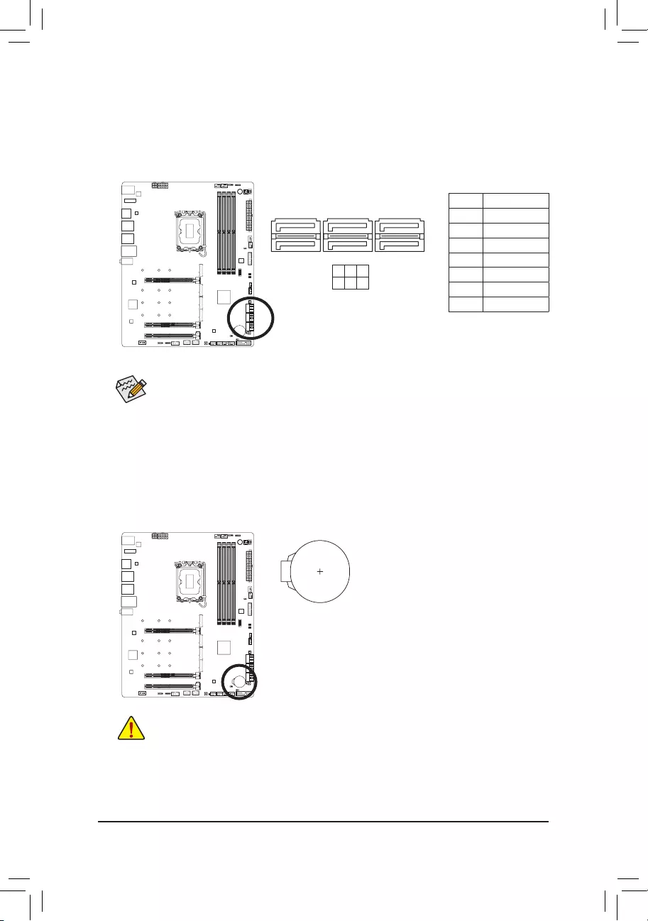
11) SATA3 2/3/4/5/6/7 (SATA 6Gb/s Connectors)
The SATA connectors conform to SATA 6Gb/s standard and are compatible with SATA 3Gb/s and SATA 1.5Gb/s
standard. Each SATA connector supports a single SATA device. The Intel® Chipset supports RAID 0, RAID 1,
RAID 5, and RAID 10. Please navigate to the «Conguring a RAID Set» page of GIGABYTE’s website for
instructions on conguring a RAID array.
Pin No. Denition
1 GND
2 TXP
3 TXN
4 GND
5 RXN
6 RXP
7 GND
SATA3 3 5 7
2 4 6
To enable hot-plugging for the SATA ports, please navigate to the «BIOS Setup» page of GIGABYTE’s
website and search for «SATA Conguration» for more information.
1
1
7
7
12) BAT (Battery)
The battery provides power to keep the values (such as BIOS congurations, date, and time information)
in the CMOS when the computer is turned off. Replace the battery when the battery voltage drops to a low
level, or the CMOS values may not be accurate or may be lost.
You may clear the CMOS values by removing the battery:
1. Turn off your computer and unplug the power cord.
2. Gently remove the battery from the battery holder and wait for one minute.
(Or use a metal object like a screwdriver to touch the positive and negative
terminals of the battery holder, making them short for 5 seconds.)
3. Replace the battery.
4. Plug in the power cord and restart your computer.
•Always turn off your computer and unplug the power cord before replacing the battery.
•Replace the battery with an equivalent one. Damage to your devices may occur if the battery is
replaced with an incorrect model.
•Contact the place of purchase or local dealer if you are not able to replace the battery by yourself
or uncertain about the battery model.
•When installing the battery, note the orientation of the positive side (+) and the negative side (-)
of the battery (the positive side should face up).
•Used batteries must be handled in accordance with local environmental regulations.
— 29 —
The front panel design may differ by chassis. A front panel module mainly consists of power switch,
reset switch, power LED, hard drive activity LED, speaker and etc. When connecting your chassis
front panel module to this header, make sure the wire assignments and the pin assignments are
matched correctly.
13) F_PANEL (Front Panel Header)
Connect the power switch, reset switch, speaker, chassis intrusion switch/sensor and system status indicator
on the chassis to this header according to the pin assignments below. Note the positive and negative pins
before connecting the cables.
•PW (Power Switch):
Connects to the power switch on the chassis front panel. You may congure the way to turn off your
system using the power switch (please navigate to the «BIOS Setup» page of GIGABYTE’s website and
search for «Soft-Off by PWR-BTTN» for more information).
•SPEAK (Speaker):
Connects to the speaker on the chassis front panel. The system reports system startup status by issuing
a beep code. One single short beep will be heard if no problem is detected at system startup.
•HD (Hard Drive Activity LED):
Connects to the hard drive activity LED on the chassis front panel. The LED is on when the hard drive
is reading or writing data.
•RES (Reset Switch):
Connects to the reset switch on the chassis front panel. Press the reset switch to restart the computer
if the computer freezes and fails to perform a normal restart.
•CI (Chassis Intrusion Header):
Connects to the chassis intrusion switch/sensor on the chassis that can detect if the chassis cover has
been removed. This function requires a chassis with a chassis intrusion switch/sensor.
•NC: No connection.
•PLED/PWR_LED (Power LED):
Connects to the power status indicator on the chassis front panel. The LED
is on when the system is operating. The LED is off when the system is in S3/
S4 sleep state or powered off (S5).
System Status LED
S0 On
S3/S4/S5 Off
NC
NC
Power LED
1
2
19
20
CI-
CI+
PWR_LED-
PWR_LED+
PLED-
PW-
SPEAK+
SPEAK-
PLED+
PW+
Power LED
HD-
RES+
HD+
RES-
Hard Drive
Activity LED
Reset
Switch Chassis Intrusion
Header
Power Switch Speaker
PWR_LED-
— 30 —
14) F_AUDIO (Front Panel Audio Header)
The front panel audio header supports High Denition audio (HD). You may connect your chassis front
panel audio module to this header. Make sure the wire assignments of the module connector match the
pin assignments of the motherboard header. Incorrect connection between the module connector and the
motherboard header will make the device unable to work or even damage it.
Pin No. Denition
1 MIC2_L
2 GND
3 MIC2_R
4 NC
5 LINE2_R
6 Sense
7 GND
8 No Pin
9 LINE2_L
10 Sense
F_USB30 F_U
B_
F_ F_
_
B
BS_
B
SB_
B
_S
S_
_
B
_U
_
B
S
123
123
123
123
1
1
1
1
BSS
S
_S
SSU
1 2 3
S3 BSSS
U
__ 3
F_USB3F
S _
S _
S _
SF
B_
B_
F
_0
S
S
_0F
_F
_
_
__B
U
S _S
_ SF_
B
USB0_B
B_
B_
F_USB3
F_USB303
_
_3U
S_
_S
SS_F
_
9 1
10 2
Some chassis provide a front panel audio module that has separated connectors on each wire
instead of a single plug. For information about connecting the front panel audio module that has
different wire assignments, please contact the chassis manufacturer.
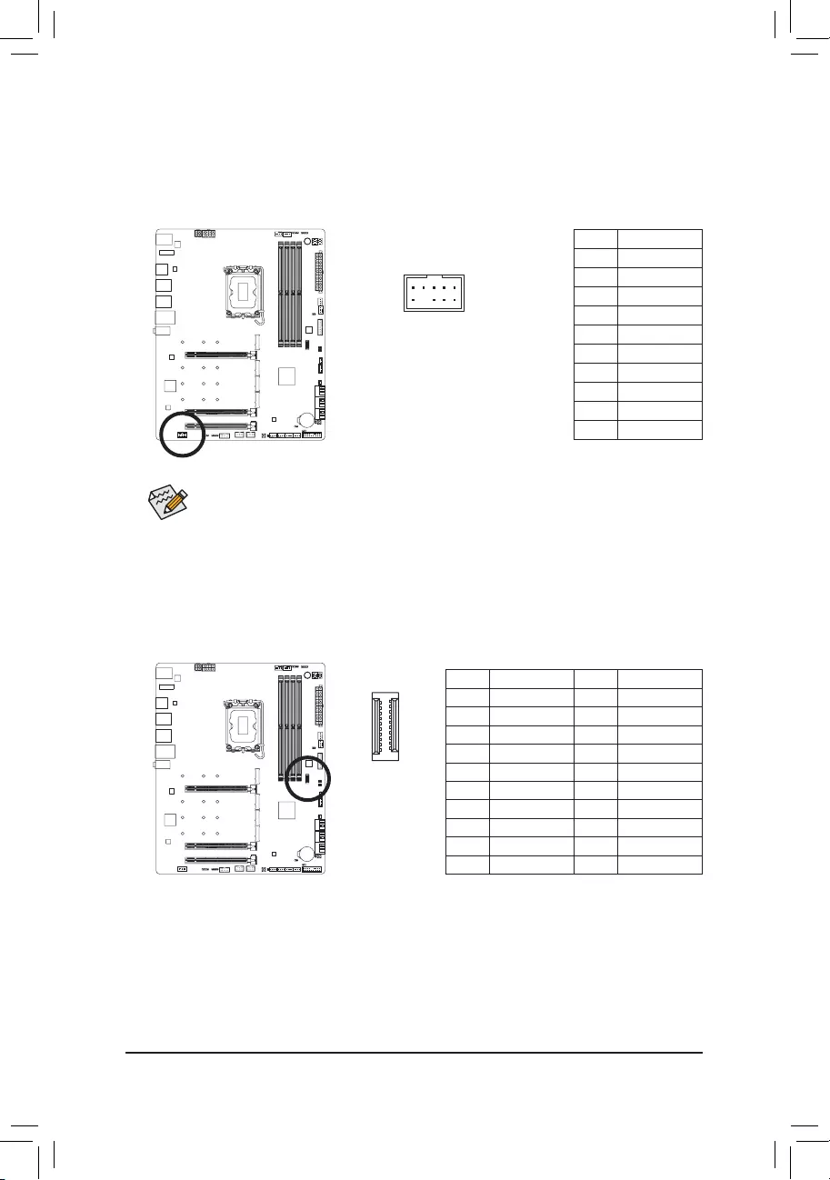
15) F_U320G (USB Type-C® Header with USB 3.2 Gen 2×2 Support)
The header conforms to USB 3.2 Gen 2×2 specication and can provide one USB port.
Pin No. Denition Pin No. Denition
1 VBUS 11 VBUS
2 TX1+ 12 TX2+
3 TX1- 13 TX2-
4 GND 14 GND
5 RX1+ 15 RX2+
6 RX1- 16 RX2-
7 VBUS 17 GND
8 CC1 18 D-
9 SBU1 19 D+
10 SBU2 20 CC2
F_USB30 F_U
B_
F_ F_
_
B
BS_
B
SB_
B
_S
S_
_
B
_U
_
B
S
123
123
123
123
1
1
1
1
BSS
S
_S
SSU
1 2 3
S3 BSSS
U
__ 3
F_USB3F
S _
S _
S _
SF
B_
B_
F
_0
S
S
_0F
_F
_
_
__B
U
S _S
_ SF_
B
USB0_B
B_
B_
F_USB3
F_USB303
_
_3U
S_
_S
SS_F
_
20
10 11
1
— 31 —
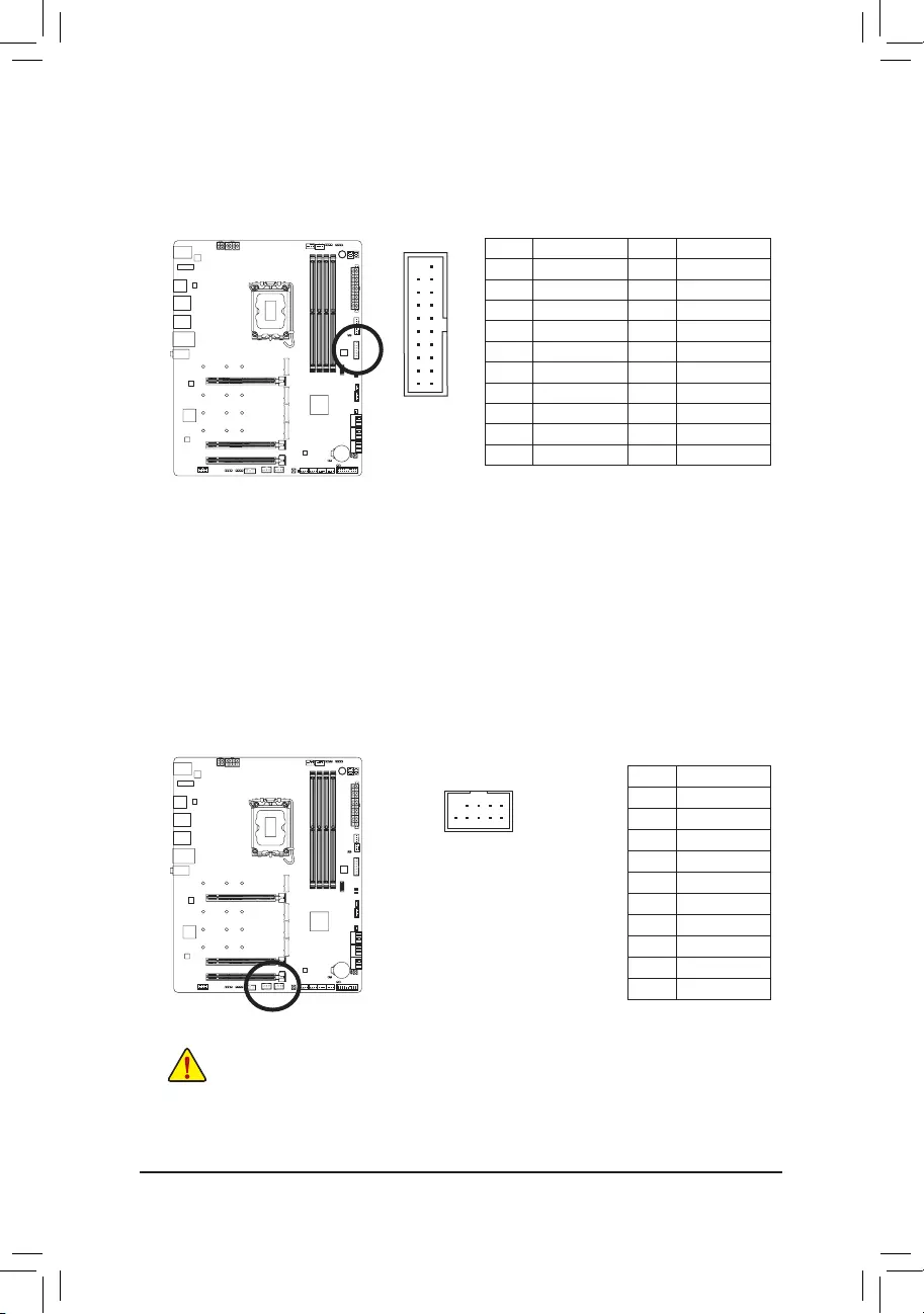
16) F_U32 (USB 3.2 Gen 1 Header)
The header conforms to USB 3.2 Gen 1 and USB 2.0 specication and can provide two USB ports. For
purchasing the optional 3.5″ front panel that provides two USB 3.2 Gen 1 ports, please contact the local
dealer.
Pin No. Denition Pin No. Denition
1 VBUS 11 D2+
2 SSRX1- 12 D2-
3 SSRX1+ 13 GND
4 GND 14 SSTX2+
5 SSTX1- 15 SSTX2-
6SSTX1+ 16 GND
7 GND 17 SSRX2+
8 D1- 18 SSRX2-
9 D1+ 19 VBUS
10 NC 20 No Pin
F_USB30 F_U
B_
F_ F_
_
B
BS_
B
SB_
B
_S
S_
_
B
_U
_
B
S
123
123
123
123
1
1
1
1
BSS
S
_S
SSU
1 2 3
S3 BSSS
U
__ 3
F_USB3F
S _
S _
S _
SF
B_
B_
F
_0
S
S
_0F
_F
_
_
__B
U
S _S
_ SF_
B
USB0_B
B_
B_
F_USB3
F_USB303
_
_3U
S_
_S
SS_F
_
20 1
1011
17) F_USB1/F_USB2 (USB 2.0/1.1 Headers)
The headers conform to USB 2.0/1.1 specication. Each USB header can provide two USB ports via an
optional USB bracket. For purchasing the optional USB bracket, please contact the local dealer.
Pin No. Denition
1 Power (5V)
2 Power (5V)
3 USB DX-
4 USB DY—
5 USB DX+
6 USB DY+
7 GND
8 GND
9 No Pin
10 NC
10
9
2
1
•Do not plug the IEEE 1394 bracket (2×5-pin) cable into the USB 2.0/1.1 header.
•Prior to installing the USB bracket, be sure to turn off your computer and unplug the power cord
from the power outlet to prevent damage to the USB bracket.
— 32 —
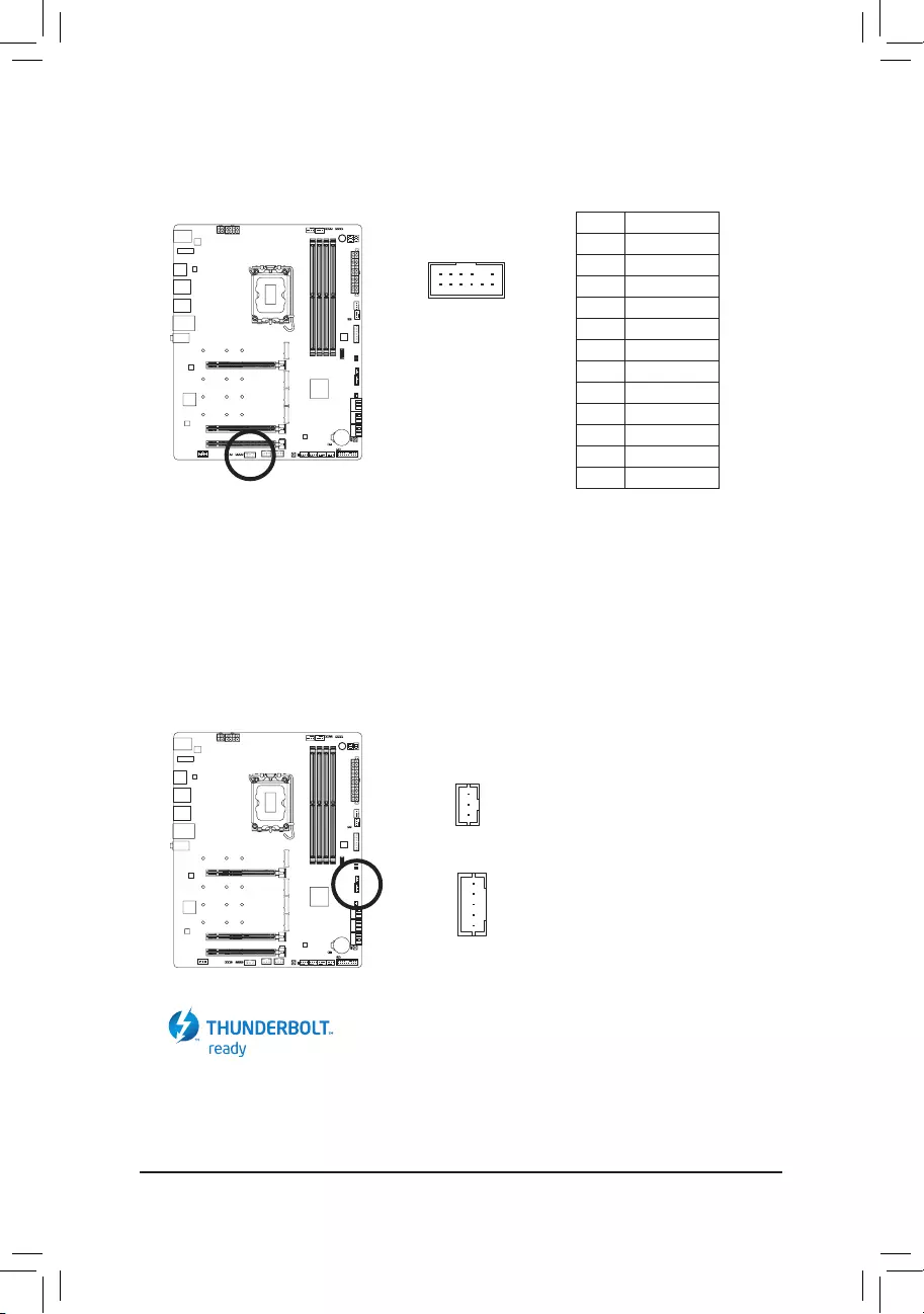
Pin No. Denition
1Data Output
2Power (3.3V)
3No Pin
4NC
5Data Input
6CLK
7Chip Select
8GND
9IRQ
10 NC
11 NC
12 RST
18) SPI_TPM (Trusted Platform Module Header)
You may connect an SPI TPM (Trusted Platform Module) to this header.
19) THB_C1/THB_C2 (Thunderbolt™ Add-in Card Connectors)
The connectors are used to connect to a GIGABYTE Thunderbolt™ add-in card.
Supports a Thunderbolt™ add-in card.
F_USB30 F_U
B_
F_ F_
_
B
BS_
B
SB_
B
_S
S_
_
B
_U
_
B
S
123
123
123
123
1
1
1
1
BSS
S
_S
SSU
1 2 3
S3 BSSS
U
__ 3
F_USB3F
S _
S _
S _
SF
B_
B_
F
_0
S
S
_0F
_F
_
_
__B
U
S _S
_ SF_
B
USB0_B
B_
B_
F_USB3
F_USB303
_
_3U
S_
_S
SS_F
_
F_USB30 F_U
B_
F_ F_
_
B
BS_
B
SB_
B
_S
S_
_
B
_U
_
B
S
123
123
123
123
1
1
1
1
BSS
S
_S
SSU
1 2 3
S3 BSSS
U
__ 3
F_USB3F
S _
S _
S _
SF
B_
B_
F
_0
S
S
_0F
_F
_
_
__B
U
S _S
_ SF_
B
USB0_B
B_
B_
F_USB3
F_USB303
_
_3U
S_
_S
SS_F
_
1
1
THB_C2
THB_C1
12
11
2
1
F_USB30 F_U
B_
F_ F_
_
B
BS_
B
SB_
B
_S
S_
_
B
_U
_
B
S
123
123
123
123
1
1
1
1
BSS
S
_S
SSU
1 2 3
S3 BSSS
U
__ 3
F_USB3F
S _
S _
S _
SF
B_
B_
F
_0
S
S
_0F
_F
_
_
__B
U
S _S
_ SF_
B
USB0_B
B_
B_
F_USB3
F_USB303
_
_3U
S_
_S
SS_F
_
— 33 —
21) CLR_CMOS (Clear CMOS Jumper)
Use this jumper to clear the BIOS conguration and reset the CMOS values to factory defaults. To clear
the CMOS values, use a metal object like a screwdriver to touch the two pins for a few seconds.
•Always turn off your computer and unplug the power cord from the power outlet before clearing
the CMOS values.
•After system restart, go to BIOS Setup to load factory defaults (select Load Optimized Defaults) or
manually congure the BIOS settings (please navigate to the «BIOS Setup» page of GIGABYTE’s
website for more information).
Open: Normal
Short: Clear CMOS Values
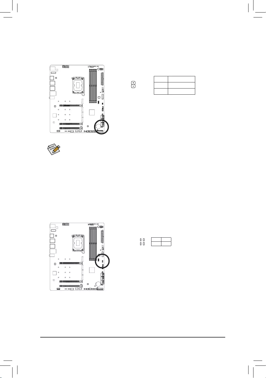
20) NOISE_SENSOR (Noise Detection Header)
This header can be used to connect a noise detection cable to detect the noise inside the case.
Pin No. Denition
1 Noise Detection
2 GND
Before connecting the cable to the header, make sure to remove the jumper cap; re-place the
jumper cap if the header is not in use.
For more information on the noise detection function, please navigate to the «Unique Features»
page of GIGABYTE’s website and search for «System Information Viewer.»
Noise Detection
Cable
1
1
— 34 —
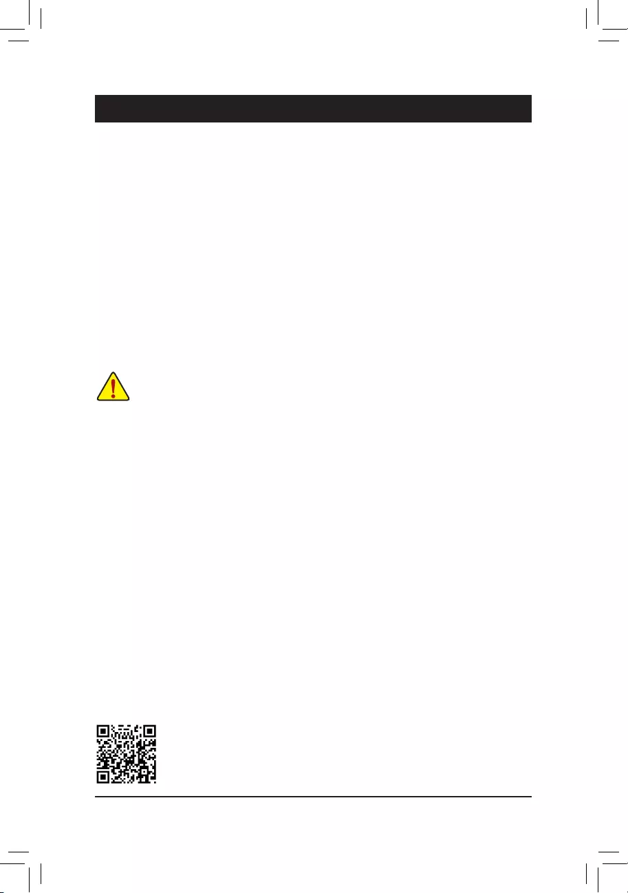
22) RST (Reset Jumper)
The reset jumper can connect to the reset switch on the chassis front panel. Press the reset switch to
restart the computer if the computer freezes and fails to perform a normal restart.
Pin No. Denition
1 Reset
2 GND
The reset jumper provides you with several functions to use. To remap the button to perform different
tasks, please navigate to the «BIOS Setup» page of GIGABYTE’s website and search for «RST_SW
(MULTIKEY)» for more information.
1
23) Status LEDs
The status LEDs show whether the CPU, memory, graphics card, and operating system are working
properly after system power-on. If the CPU/DRAM/VGA LED is on, that means the corresponding device
is not working normally; if the BOOT LED is on, that means you haven’t entered the operating system yet.
CPU: CPU status LED
DRAM: Memory status LED
VGA: Graphics card status LED
BOOT: Operating system status LED
F_USB30 F_U
B_
F_ F_
_
B
BS_
B
SB_
B
_S
S_
_
B
_U
_
B
S
123
123
123
123
1
1
1
1
BSS
S
_S
SSU
1 2 3
S3 BSSS
U
__ 3
F_USB3F
S _
S _
S _
SF
B_
B_
F
_0
S
S
_0F
_F
_
_
__B
U
S _S
_ SF_
B
USB0_B
B_
B_
F_USB3
F_USB303
_
_3U
S_
_S
SS_F
_
CPU DRAM
VGA BOOT
— 35 —
BIOS (Basic Input and Output System) records hardware parameters of the system in the CMOS on the
motherboard. Its major functions include conducting the Power-On Self-Test (POST) during system startup,
saving system parameters and loading operating system, etc. BIOS includes a BIOS Setup program that allows
the user to modify basic system conguration settings or to activate certain system features.
When the power is turned off, the battery on the motherboard supplies the necessary power to the CMOS to
keep the conguration values in the CMOS.
To access the BIOS Setup program, press the <Delete> key during the POST when the power is turned on.
To upgrade the BIOS, use either the GIGABYTE Q-Flash or @BIOS utility.
•Q-Flash allows the user to quickly and easily upgrade or back up BIOS without entering the operating system.
•@BIOS is a Windows-based utility that searches and downloads the latest version of BIOS from the Internet
and updates the BIOS.
For instructions on using the Q-Flash and @BIOS utilities, please navigate to the «Unique Features» page of
GIGABYTE’s website and search for «BIOS Update Utilities.»
Chapter 3 BIOS Setup
•Because BIOS ashing is potentially risky, if you do not encounter problems using the current
version of BIOS, it is recommended that you not ash the BIOS. To ash the BIOS, do it with
caution. Inadequate BIOS ashing may result in system malfunction.
•It is recommended that you not alter the default settings (unless you need to) to prevent system
instability or other unexpected results. Inadequately altering the settings may result in system’s
failure to boot. If this occurs, try to clear the CMOS values and reset the board to default values.
•Refer to the introductions of the battery/clear CMOS jumper in Chapter 2 or navigate to the «BIOS
Setup» page of GIGABYTE’s website and search for «Load Optimized Defaults» for how to clear
the CMOS values.
Please visit GIGABYTE’s website for details on conguring BIOS Setup.
— 36 —
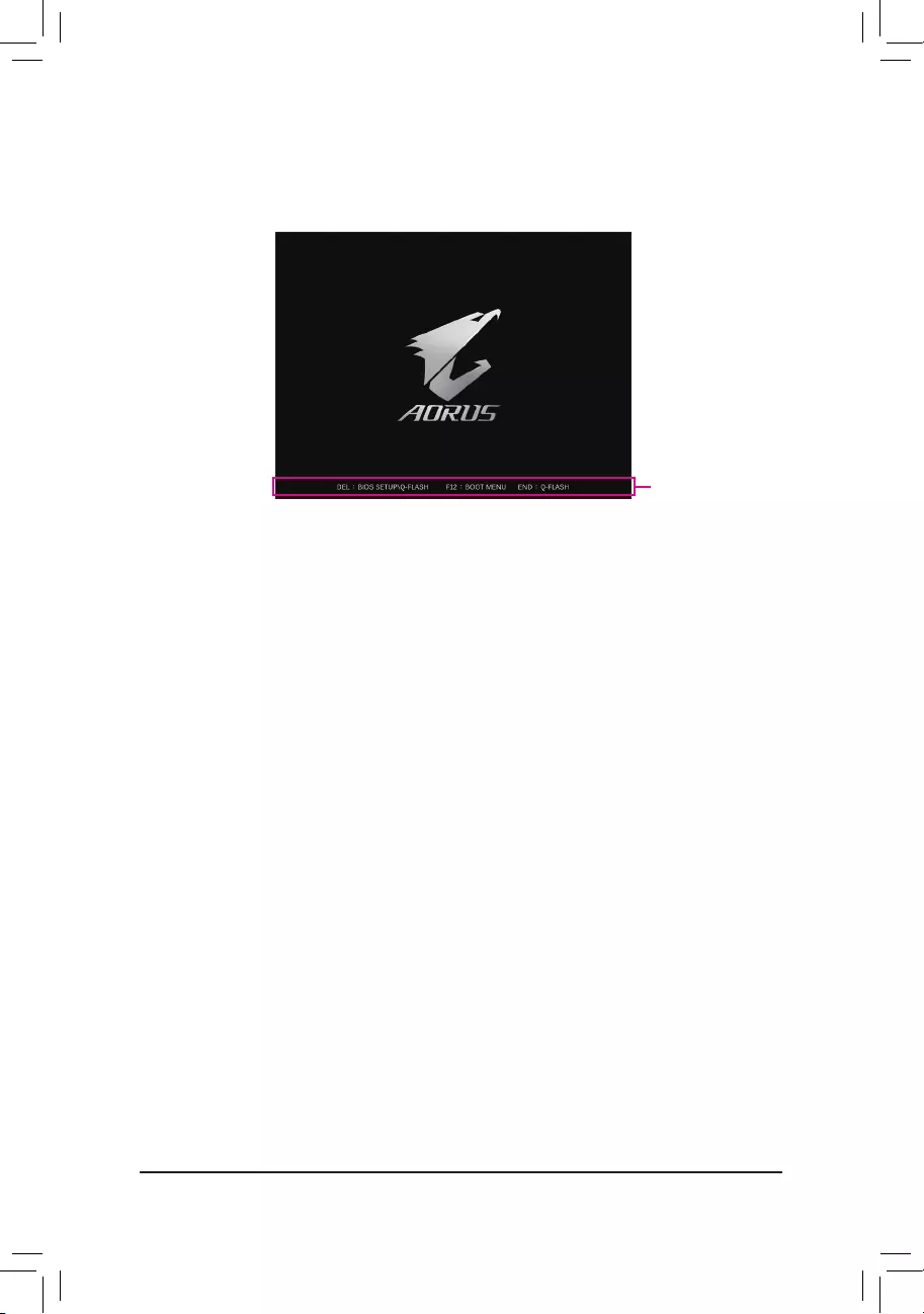
Startup Screen:
Function Keys:
<DEL>: BIOS SETUP\Q-FLASH
Press the <Delete> key to enter BIOS Setup or to access the Q-Flash utility in BIOS Setup.
<F12>: BOOT MENU
Boot Menu allows you to set the rst boot device without entering BIOS Setup. In Boot Menu, use the up
arrow key <h> or the down arrow key <i> to select the rst boot device, then press <Enter> to accept.
The system will boot from the device immediately.
Note: The setting in Boot Menu is effective for one time only. After system restart, the device boot order
will still be based on BIOS Setup settings.
<END>: Q-FLASH
Press the <End> key to access the Q-Flash utility directly without having to enter BIOS Setup rst.
Function Keys
The following startup Logo screen will appear when the computer boots.
— 37 —
Chapter 4 Installing the Operating System and Drivers
4-1 Operating System Installation
With the correct BIOS settings, you are ready to install the operating system.
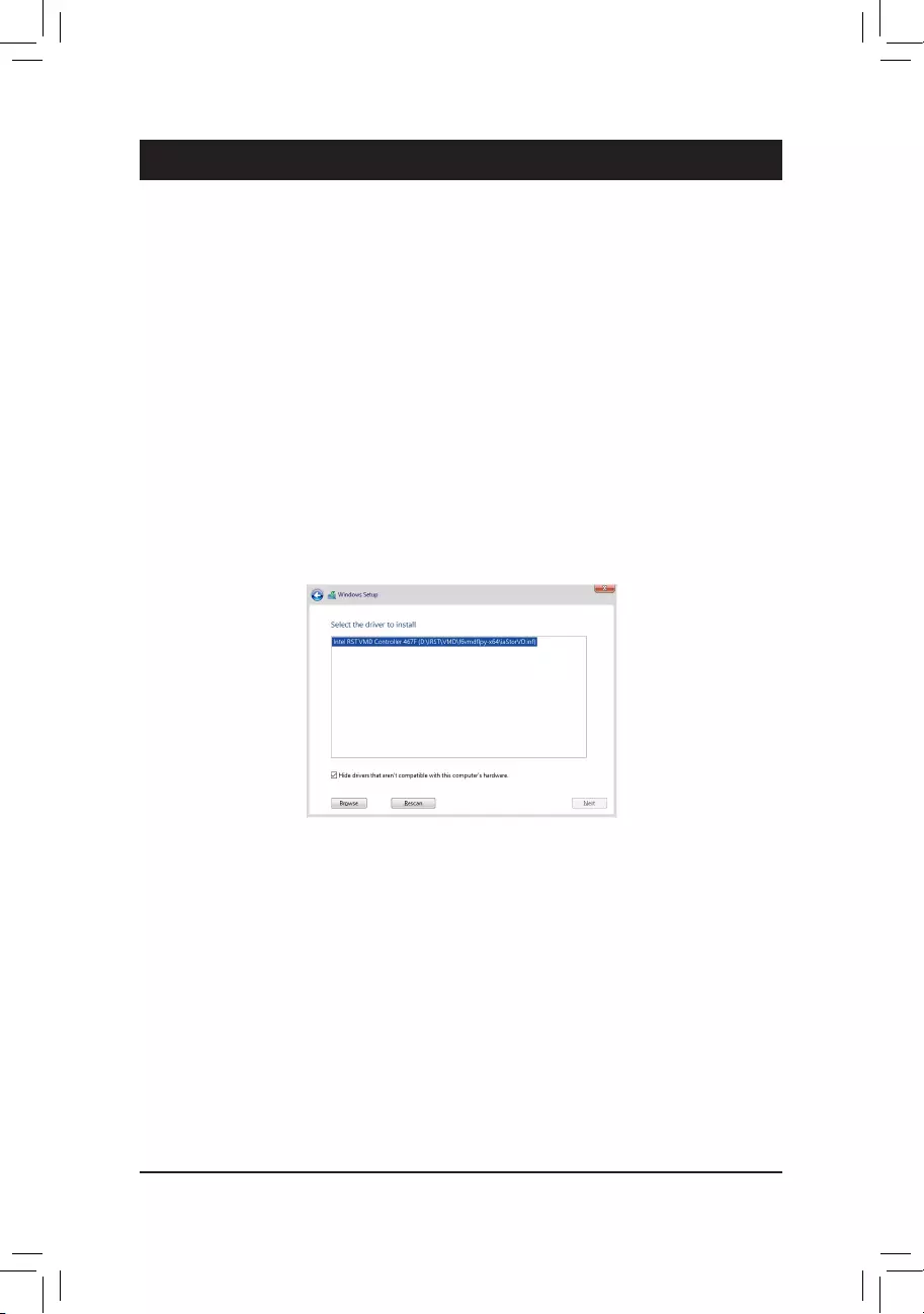
If you want to install an operating system on an M.2 PCIe SSD or a RAID volume, you need to install the Intel®
RST VMD Controller driver rst during the OS installation process. Refer to the steps below:
Step 1:
Go to GIGABYTE’s website, browse to the motherboard model’s web page, download the Intel SATA Preinstall
driver le on the Support\Download\SATA RAID/AHCI page, unzip the le and copy the les to your USB
thumb drive.
Step 2:
Boot from the Windows setup disc and perform standard OS installation steps. When the screen requesting you
to load the driver appears, select Browse.
Step 3:
Insert the USB thumb drive and then browse to the location of the driver. When a screen as shown below
appears, select Intel RST VMD Controller 467F and click Next to load the driver and continue the OS installation.
— 38 —
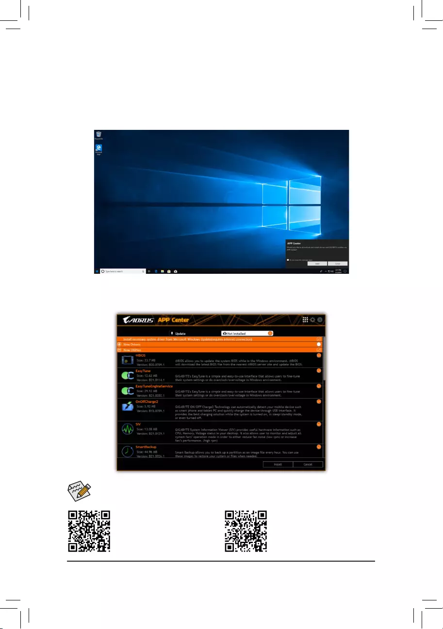
4-2 Drivers Installation
After you install the operating system, a dialog box will appear on the bottom-right corner of the desktop asking
if you want to download and install the drivers and GIGABYTE applications via APP Center. Click Install to
proceed with the installation. (In BIOS Setup, make sure Settings\IO Ports\APP Center Download & Install
Conguration\APP Center Download & Install is set to Enabled.)
Please visit GIGABYTE’s website for
more software information.
Please visit GIGABYTE’s website for
more troubleshooting information.
Before the installation, make sure the system is connected to the Internet.
When the End User License Agreement dialog box appears, press <Accept> to install APP Center. On the APP
Center screen, select the drivers and applications you want to install and click Install.
— 39 —
Chapter 5 Appendix
5-1 Conguring a RAID Set
RAID Levels
Before you begin, please prepare the following items:
This motherboard supports RAID 0, RAID 1, RAID 5, and RAID 10. Prepare the correct number of hard drives
as indicated in the table above before conguring a RAID array.
•SATA hard drives or SSDs. To ensure optimal performance, it is recommended that you use two hard drives
with identical model and capacity.
•Windows setup disc.
•An Internet connected computer.
•A USB thumb drive.
Please visit GIGABYTE’s website for details on conguring a RAID array.
•An M.2 PCIe SSD cannot be used to set up a RAID set either with an M.2 SATA SSD or a SATA
hard drive.
•Refer to «Internal Connectors,» for the installation notices for the M.2 and SATA connectors.
RAID 0 RAID 1 RAID 5 RAID 10
Minimum
Number of Hard
Drives
≥2 2≥3 4
Array Capacity
Number of hard
drives * Size of the
smallest drive
Size of the smallest
drive
(Number of hard
drives -1) * Size of
the smallest drive
(Number of hard
drives/2) * Size of the
smallest drive
Fault Tolerance No Yes Yes Yes
— 40 —
5-2 Debug LED Codes
Code Description
10 PEI Core is started.
11 Pre-memory CPU initialization is started.
12~14 Reserved.
15 Pre-memory North-Bridge initialization is started.
16~18 Reserved.
19 Pre-memory South-Bridge initialization is started.
1A~2A Reserved.
2B~2F Memory initialization.
31 Memory installed.
32~36 CPU PEI initialization.
37~3A IOH PEI initialization.
3B~3E PCH PEI initialization.
3F~4F Reserved.
60 DXE Core is started.
61 NVRAM initialization.
62 Installation of the PCH runtime services.
63~67 CPU DXE initialization is started.
68 PCI host bridge initialization is started.
69 IOH DXE initialization.
6A IOH SMM initialization.
6B~6F Reserved.
70 PCH DXE initialization.
71 PCH SMM initialization.
72 PCH devices initialization.
73~77 PCH DXE initialization (PCH module specic).
78 ACPI Core initialization.
79 CSM initialization is started.
7A~7F Reserved for AMI use.
80~8F Reserved for OEM use (OEM DXE initialization codes).
90 Phase transfer to BDS (Boot Device Selection) from DXE.
91 Issue event to connect drivers.
Regular Boot
— 41 —
Code Description
92 PCI Bus initialization is started.
93 PCI Bus hot plug initialization.
94 PCI Bus enumeration for detecting how many resources are requested.
95 Check PCI device requested resources.
96 Assign PCI device resources.
97 Console Output devices connect (ex. Monitor is lighted).
98 Console input devices connect (ex. PS2/USB keyboard/mouse are activated).
99 Super IO initialization.
9A USB initialization is started.
9B Issue reset during USB initialization process.
9C Detect and install all currently connected USB devices.
9D Activated all currently connected USB devices.
9E~9F Reserved.
A0 IDE initialization is started.
A1 Issue reset during IDE initialization process.
A2 Detect and install all currently connected IDE devices.
A3 Activated all currently connected IDE devices.
A4 SCSI initialization is started.
A5 Issue reset during SCSI initialization process.
A6 Detect and install all currently connected SCSI devices.
A7 Activated all currently connected SCSI devices.
A8 Verify password if needed.
A9 BIOS Setup is started.
AA Reserved.
AB Wait user command in BIOS Setup.
AC Reserved.
AD Issue Ready To Boot event for OS Boot.
AE Boot to Legacy OS.
AF Exit Boot Services.
B0 Runtime AP installation begins.
B1 Runtime AP installation ends.
B2 Legacy Option ROM initialization.
B3 System reset if needed.
— 42 —
Code Description
B4 USB device hot plug-in.
B5 PCI device hot plug.
B6 Clean-up of NVRAM.
B7 Recongure NVRAM settings.
B8~BF Reserved.
C0~CF Reserved.
Code Description
E0 S3 Resume is stared (called from DXE IPL).
E1 Fill boot script data for S3 resume.
E2 Initializes VGA for S3 resume.
E3 OS S3 wake vector call.
S3 Resume
Code Description
F0 Recovery mode will be triggered due to invalid rmware volume detection.
F1 Recovery mode will be triggered by user decision.
F2 Recovery is started.
F3 Recovery rmware image is found.
F4 Recovery rmware image is loaded.
F5~F7 Reserved for future AMI progress codes.
Recovery
Code Description
50~55 Memory initialization error occurs.
56 Invalid CPU type or speed.
57 CPU mismatch.
58 CPU self test failed or possible CPU cache error.
59 CPU micro-code is not found or micro-code update is failed.
5A Internal CPU error.
5B Reset PPI is failed.
5C~5F Reserved.
D0 CPU initialization error.
D1 IOH initialization error.
Error
— 43 —
Code Description
D2 PCH initialization error.
D3 Some of the Architectural Protocols are not available.
D4 PCI resource allocation error. Out of Resources.
D5 No Space for Legacy Option ROM initialization.
D6 No Console Output Devices are found.
D7 No Console Input Devices are found.
D8 It is an invalid password.
D9~DA Can’t load Boot Option.
DB Flash update is failed.
DC Reset protocol is failed.
DE~DF Reserved.
E8 S3 resume is failed.
E9 S3 Resume PPI is not found.
EA S3 Resume Boot Script is invalid.
EB S3 OS Wake call is failed.
EC~EF Reserved.
F8 Recovery PPI is invalid.
<F9> Recovery capsule is not found.
FA Invalid recovery capsule.
FB~FF Reserved.
— 44 —
Supplier’s Declaration of Conformity
47 CFR § 2.1077 Compliance Information
Product Name: Motherboard
Trade Name: GIGABYTE
Model Number: Z690 AORUS PRO/Z690 AORUS PRO DDR4
Responsible Party – U.S. Contact Information: G.B.T. Inc.
Address: 17358 Railroad street, City Of Industry, CA91748
Tel.: 1-626-854-9338
Internet contact information: https://www.gigabyte.com
FCC Compliance Statement:
This device complies with Part 15 of the FCC Rules, Subpart B, Unintentional Radiators.
Operation is subject to the following two conditions: (1) This device may not cause harmful interference, and (2) this
device must accept any interference received, including interference that may cause undesired operation.
Antenna use:
In order to comply with FCC RF exposure limits, low gain integrated
antennas should be located at a minimum distance of 7.9 inches (20 cm)
or more from the body of all persons.
Explosive Device Proximity Warning
Warning: Do not operate a portable transmitter (such as a wireless network
device) near unshielded blasting caps or in an explosive environment
unless the device has been modied to be qualied for such use.
Antenna Warning
The wireless adapter is not designed for use with high-gain antennas.
Use On Aircraft Caution
Caution: Regulations of the FCC and FAA prohibit airborne operation of
radio-frequency wireless devices because their signals could interfere with
critical aircraft instruments.
Other Wireless Devices
Safety Notices for Other Devices in the Wireless Network: Refer to the
documentation supplied with wireless Ethernet adapters or other devices
in the wireless network.
Canada, Canada-Industry Notice:
This device complies with Industry Canada license-exempt RSS
standard(s). Operation is subject to the following two conditions:
(1) this device may not cause interference, and
(2) this device must accept any interference, including interference that
may cause undesired operation of the device.
Cet appareil est conforme aux normes Canada d’Industrie de RSS
permis-exempt. L’utilisation est assujetti aux deux conditions suivantes:
(1) le dispositif ne doit pas produire de brouillage préjudiciable, et
(2) ce dispositif doit accepter tout brouillage reçu, y compris un brouillage
susceptible de provoquer un fonctionnement indésirable.
Caution: When using IEEE 802.11a wireless LAN, this product is restricted
to indoor use due to its operation in the 5.15-to 5.25-GHz frequency
range. Industry Canada requires this product to be used indoors for the
frequency range of 5.15 GHz to 5.25 GHz to reduce the potential for
harmful interference to co-channel mobile satellite systems. High power
radar is allocated as the primary user of the 5.25-to 5.35-GHz and 5.65 to
5.85-GHz bands. These radar stations can cause interference with and/or
damage to this device. The maximum allowed antenna gain for use with
this device is 6dBi in order tocomply with the E.I.R.P limit for the 5.25-to
5.35 and 5.725 to 5.85 GHz frequency range in point-to-point operation. To
comply with RF exposure requirements all antennas should be located at a
minimum distance of 20cm, or the minimum separation distance allowed
by the module approval, from the body of all persons.
Attention: l’utilisation d’un réseau sans l IEEE802.11a est restreinte à
une utilisation en intérieur à cause du fonctionnement dansla bande de
fréquence 5.15-5.25 GHz. Industry Canada requiert que ce produit soit
utilisé à l’intérieur des bâtiments pour la bande de fréquence 5.15-5.25
GHz an de réduire les possibilités d’interférences nuisibles aux canaux
co-existants des systèmes de transmission satellites. Les radars de
puissances ont fait l’objet d’une allocation primaire de fréquences dans
les bandes 5.25-5.35 GHz et 5.65-5.85 GHz. Ces stations radar peuvent
créer des interférences avec ce produit et/ou lui être nuisible. Le gain
d’antenne maximum permissible pour une utilisation avec ce produit est de
6 dBi an d’être conforme aux limites de puissance isotropique rayonnée
équivalente (P.I.R.E.) applicable.
dans les bandes 5.25-5.35 GHz et 5.725-5.85 GHz en fonctionnement
point-à-point. Pour se conformer aux conditions d’exposition de RF toutes
les antennes devraient être localisées à une distance minimum de 20
cm, ou la distance de séparation minimum permise par l’approbation du
module, du corps de toutes les personnes.
Regulatory Notices
United States of America, Federal Communications Commission Statement
The FCC with its action in ET Docket 96-8 has adopted a safety standard for human exposure to radio frequency (RF) electromagnetic energy emitted
by FCC certied equipment. The Intel PRO/Wireless 5000 LAN products meet the Human Exposure limits found in OET Bulletin 65, 2001, and ANSI/
IEEE C95.1, 1992. Proper operation of this radio according to the instructions found in this manual will result in exposure substantially below the FCC’s
recommended limits.
The following safety precautions should be observed:
•Do not touch or move antenna while the unit is transmitting or receiving.
•Do not hold any component containing the radio such that the antenna is very close or touching any exposed parts of the body, especially the face
or eyes, while transmitting.
•Do not operate the radio or attempt to transmit data unless the antenna is connected; if not, the radio may be damaged.
•Use in specic environments:
— The use of wireless devices in hazardous locations is limited by the constraints posed by the safety directors of such environments.
— The use of wireless devices on airplanes is governed by the Federal Aviation Administration (FAA).
— The use of wireless devices in hospitals is restricted to the limits set forth by each hospital.
— 45 —
European Union (EU) CE Declaration of Conformity
This device complies with the following directives: Electromagnetic
Compatibility Directive 2014/30/EU, Low-voltage Directive 2014/35/EU,
Radio Equipment Directive 2014/53/EU, ErP Directive 2009/125/EC, RoHS
directive (recast) 2011/65/EU & the 2015/863 Statement.
This product has been tested and found to comply with all essential
requirements of the Directives.
European Union (EU) RoHS (recast) Directive 2011/65/EU & the
European Commission Delegated Directive (EU) 2015/863 Statement
GIGABYTE products have not intended to add and safe from hazardous
substances (Cd, Pb, Hg, Cr+6, PBDE, PBB, DEHP, BBP, DBP and DIBP).
The parts and components have been carefully selected to meet RoHS
requirement. Moreover, we at GIGABYTE are continuing our efforts to
develop products that do not use internationally banned toxic chemicals.
European Union (EU) Community Waste Electrical & Electronic
Equipment (WEEE) Directive Statement
GIGABYTE will fulll the national laws as interpreted from the 2012/19/
EU WEEE (Waste Electrical and Electronic Equipment) (recast) directive.
The WEEE Directive species the treatment, collection, recycling and
disposal of electric and electronic devices and their components. Under
the Directive, used equipment must be marked, collected separately, and
disposed of properly.
WEEE Symbol Statement
The symbol shown below is on the product or on its
packaging, which indicates that this product must not be
disposed of with other waste. Instead, the device should be
taken to the waste collection centers for activation of the
treatment, collection, recycling and disposal procedure.
For more information about where you can drop off your waste equipment
for recycling, please contact your local government ofce, your household
waste disposal service or where you purchased the product for details of
environmentally safe recycling.
End of Life Directives-Recycling
The symbol shown below is on the product or on its packaging,
which indicates that this product must not be disposed of with
other waste. Instead, the device should be taken to the waste
collection centers for activation of the treatment, collection,
recycling and disposal procedure.
Déclaration de Conformité aux Directives de l’Union européenne (UE)
Cet appareil portant la marque CE est conforme aux directives de l’UE
suivantes: directive Compatibilité Electromagnétique 2014/30/UE, directive
Basse Tension 2014/35/UE, directive équipements radioélectriques
2014/53/UE, la directive RoHS II 2011/65/UE & la déclaration 2015/863.
La conformité à ces directives est évaluée sur la base des normes
européennes harmonisées applicables.
European Union (EU) CE-Konformitätserklärung
Dieses Produkte mit CE-Kennzeichnung erfüllen folgenden EU-Richtlinien:
EMV-Richtlinie 2014/30/EU, Niederspannungsrichtlinie 2014/35/EU,
Funkanlagen Richtlinie 2014/53/EU, RoHS-Richtlinie 2011/65/EU erfüllt
und die 2015/863 Erklärung.
Die Konformität mit diesen Richtlinien wird unter Verwendung der
entsprechenden Standards zurEuropäischen Normierung beurteilt.
CE declaração de conformidade
Este produto com a marcação CE estão em conformidade com das
seguintes Diretivas UE: Diretiva Baixa Tensão 2014/35/EU; Diretiva
CEM 2014/30/EU; Diretiva RSP 2011/65/UE e a declaração 2015/863.
A conformidade com estas diretivas é vericada utilizando as normas
europeias harmonizadas.
CE Declaración de conformidad
Este producto que llevan la marca CE cumplen con las siguientes
Directivas de la Unión Europea: Directiva EMC 2014/30/EU, Directiva de
bajo voltaje 2014/35/EU, Directiva de equipamentos de rádio 2014/53/EU,
Directiva RoHS 2011/65/EU y la Declaración 2015/863.
El cumplimiento de estas directivas se evalúa mediante las normas
europeas armonizadas.
CE Dichiarazione di conformità
I prodotti con il marchio CE sono conformi con una o più delle seguenti
Direttive UE, come applicabile: Direttiva EMC 2014/30/UE, Direttiva sulla
bassa tensione 2014/35/UE, Direttiva di apparecchiature radio 2014/53/
UE, Direttiva RoHS 2011/65/EU e Dichiarazione 2015/863.
La conformità con tali direttive viene valutata utilizzando gli Standard
europei armonizzati applicabili.
Deklaracja zgodności UE Unii Europejskiej
Urządzenie jest zgodne z następującymi dyrektywami: Dyrektywa
kompatybilności elektromagnetycznej 2014/30/UE, Dyrektywa
niskonapięciowej 2014/35/UE, Dyrektywa urządzeń radiowych 2014/53/
UE, Dyrektywa RoHS 2011/65/UE i dyrektywa2015/863.
Niniejsze urządzenie zostało poddane testom i stwierdzono jego zgodność
z wymaganiami dyrektywy.
ES Prohlášení o shodě
Toto zařízení splňuje požadavky Směrnice o Elektromagnetické
kompatibilitě 2014/30/EU, Směrnice o Nízkém napětí 2014/35/EU,
Směrnice o rádiových zařízeních 2014/53/EU, Směrnice RoHS 2011/65/
EU a 2015/863.
Tento produkt byl testován a bylo shledáno, že splňuje všechny základní
požadavky směrnic.
EK megfelelőségi nyilatkozata
A termék megfelelnek az alábbi irányelvek és szabványok
követelményeinek, azok a kiállításidőpontjában érvényes, aktuális
változatában: EMC irányelv 2014/30/EU, Kisfeszültségű villamos
berendezésekre vonatkozó irányelv 2014/35/EU, rádióberendezések
irányelv 2014/53/EU, RoHS irányelv 2011/65/EU és 2015/863.
Δήλωση συμμόρφωσης ΕΕ
Είναι σε συμμόρφωση με τις διατάξεις των παρακάτω Οδηγιών
της Ευρωπαϊκής Κοινότητας: Οδηγία 2014/30/ΕΕ σχετικά με την
ηλεκτρομαγνητική συμβατότητα, Οοδηγία χαμηλή τάση 2014/35/EU,
Οδηγία 2014/53/ΕΕ σε ραδιοεξοπλισμό, Οδηγία RoHS 2011/65/ΕΕ
και 2015/863.
Η συμμόρφωση με αυτές τις οδηγίες αξιολογείται χρησιμοποιώντας τα
ισχύοντα εναρμονισμένα ευρωπαϊκά πρότυπα.
Under Industry Canada regulations, this radio transmitter may only operate
using an antenna of a type and maximum (or lesser) gain approved for
the transmitter by Industry Canada. To reduce potential radio interference
to other users, the antenna type and its gain should be chosen so that
the equivalent isotropically radiated power (e.i.r.p.) is not more than that
necessary for successful communication.
Conformément à la réglementation d’Industrie Canada, le présent émetteur
radio peut fonctionner avec une antenne d’un type et d’un gain maximal
(ou inférieur) approuvé pour l’émetteur par Industrie Canada. Dans le
but de réduire les risques de brouillage radio électrique à l’intention des
autres utilisateurs, il faut choisir le type d’antenne et son gain de sorte
que la puissance isotrope rayonnée équivalente (p.i.r.e.) ne dépasse pas
l’intensité nécessaire à l’établissement d’une communication satisfaisante.
— 46 —
European Community Radio Equipment Directive Compliance Statement:
This equipment complies with all the requirements and other relevant provisions of Radio Equipment Directive 2014/53/EU.
This equipment is suitable for home and ofce use in all the European Community Member States and EFTA Member States.
The low band 5.15 -5.35 GHz is for indoor use only.
AT BE BG CH CY CZ DE
DK EE EL ES FI FR HR
HU IE IS IT LI LT LU
LV MT NL PL PT RO SE
SI SK TR UK
Wireless module manufacturer: Intel® Corporation SAS
Wireless module model name: AX200NGW
Taiwan NCC Wireless Statements / 無線設備警告聲明:
低功率電波輻射性電機管理辦法
(1) 取得審驗證明之低功率射頻器材,非經核准,公司、商號或使用者均不得擅自變更頻率、加大功率或變更原設計之特
性及功能。低功率射頻器材之使用不得影響飛航安全及干擾合法通信;經發現有干擾現象時,應立即停用,並改善至
無干擾時方得繼續使用。前述合法通信,指依電信管理法規定作業之無線電通信。低功率射頻器材須忍受合法通信或
工業、科學及醫療用電波輻射性電機設備之干擾。
(2) 應避免影響附近雷達系統之操作。
Korea KCC NCC Wireless Statement:
5,25GHz — 5,35 GHz 대역을 사용하는 무선 장치는 실내에서만 사용하도록 제한됩니다.
Japan Wireless Statement:
5.15 GHz 帯 ~ 5.35 GHz 帯: 屋内のみの使用。
Wireless module country approvals:
Wireless module manufacturer: Intel® Corporation
Wireless module model name: AX200NGW
— 47 —

— 48 —
Contact Us
GIGA-BYTE TECHNOLOGY CO., LTD.
Address: No.6, Baoqiang Rd., Xindian Dist., New Taipei City 231, Taiwan
TEL: +886-2-8912-4000, FAX: +886-2-8912-4005
Tech. and Non-Tech. Support (Sales/Marketing) : https://esupport.gigabyte.com
WEB address (English): https://www.gigabyte.com
WEB address (Chinese): https://www.gigabyte.com/tw
•GIGABYTE eSupport
To submit a technical or non-technical (Sales/Marketing) question, please link to:
https://esupport.gigabyte.com
1,059
Views
DOWNLOAD OPTIONS
DAISY
Uplevel BACK
Temporarily Unavailable
mb_manual_600series-bios_c_daisy.zip
Temporarily Unavailable
mb_manual_600series-bios_e_daisy.zip
Temporarily Unavailable
mb_manual_600series-bios_sc_daisy.zip
Temporarily Unavailable
mb_manual_quick-guide_LGA1700_daisy.zip
Temporarily Unavailable
mb_manual_z690-aorus-pro-series_e_daisy.zip
Temporarily Unavailable
mb_manual_z690-aorus-pro-series_j_daisy.zip
Temporarily Unavailable
mb_manual_z690-aorus-pro-series_k_daisy.zip
Temporarily Unavailable
mb_manual_z690-aorus-pro-series_sc_daisy.zip
Temporarily Unavailable
mb_manual_z690-features_c_daisy.zip
Temporarily Unavailable
mb_manual_z690-features_j_daisy.zip
Temporarily Unavailable
mb_manual_z690-features_daisy.zip
Temporarily Unavailable
mb_manual_z690-features_sc_daisy.zip
Temporarily Unavailable
mb_manual_z690-raid_c_daisy.zip
Temporarily Unavailable
mb_manual_z690-raid_j_daisy.zip
Temporarily Unavailable
mb_manual_z690-raid_daisy.zip
Temporarily Unavailable
mb_manual_z690-raid_sc_daisy.zip
For users with print-disabilities
EPUB
Uplevel BACK
Temporarily Unavailable
mb_manual_600series-bios_c.epub
Temporarily Unavailable
mb_manual_600series-bios_e.epub
Temporarily Unavailable
mb_manual_600series-bios_sc.epub
Temporarily Unavailable
mb_manual_quick-guide_LGA1700.epub
Temporarily Unavailable
mb_manual_z690-aorus-pro-series_e.epub
Temporarily Unavailable
mb_manual_z690-aorus-pro-series_j.epub
Temporarily Unavailable
mb_manual_z690-aorus-pro-series_k.epub
Temporarily Unavailable
mb_manual_z690-aorus-pro-series_sc.epub
Temporarily Unavailable
mb_manual_z690-features_c.epub
Temporarily Unavailable
mb_manual_z690-features_j.epub
Temporarily Unavailable
mb_manual_z690-features.epub
Temporarily Unavailable
mb_manual_z690-features_sc.epub
Temporarily Unavailable
mb_manual_z690-raid_c.epub
Temporarily Unavailable
mb_manual_z690-raid_j.epub
Temporarily Unavailable
mb_manual_z690-raid.epub
Temporarily Unavailable
mb_manual_z690-raid_sc.epub
Uploaded by
Unknown
on
Gigabyte Z690 Aorus Pro DDR4
Z690 AORUS PRO DDR4
User’s Manual
Rev. 1101
For more product details, please visit GIGABYTE’s website.
https://www.gigabyte.com/Motherboard/Z690-AORUS-PRO-rev-10?m=ma#kf
https://www.gigabyte.com/Motherboard/Z690-AORUS-PRO-DDR4-rev-10?m=ma#kf
GIGABYTE will reduce paper use in order to fulll the responsibilities of a global citizen.
Also, to reduce the impacts on global warming, the packaging materials of this product
are recyclable and reusable. GIGABYTE works with you to protect the environment.
User manual
View the manual for the Gigabyte Z690 Aorus Pro DDR4 here, for free. This manual comes under the category motherboards and has been rated by 1 people with an average of a 9.3. This manual is available in the following languages: English. Do you have a question about the Gigabyte Z690 Aorus Pro DDR4 or do you need help?
Ask your question here
Index
- Chapter 1 Product Introduction
- Chapter 2 Hardware Installation
- Chapter 3 BIOS Setup
- Chapter 4 Installing the Operating System and Drivers
- Chapter 5 Appendix
Product Images (7)

Gigabyte Z690 Aorus Pro DDR4 specifications
Below you will find the product specifications and the manual specifications of the Gigabyte Z690 Aorus Pro DDR4.
Processor manufacturer
Intel
Supported memory types
DDR4-SDRAM
Parallel processing technology support
2-Way CrossFireX, Quad-GPU CrossFireX
Number of M.2 (M) slots
4
General
| Brand | Gigabyte |
| Model | Z690 Aorus Pro DDR4 | Z690 AORUS PRO DDR4 |
| Product | motherboard |
| EAN | 4719331827878 |
| Language | English |
| Filetype | User manual (PDF), Installation Guide (PDF) |
Processor
| Processor manufacturer | Intel |
| Processor socket | LGA 1700 |
| Compatible processor series | Intel Core i5, Intel Core i7, Intel Core i9 |
| Supported processor sockets | LGA 1700 |
Memory
| Supported memory types | DDR4-SDRAM |
| Number of memory slots | 4 |
| Memory slots type | DIMM |
| Memory channels | Dual-channel |
| Maximum internal memory | 128 GB |
| Unbuffered memory | Yes |
| Supported memory clock speeds | 2133,2400,2666,2800,2933,3000,3200,3300,3333,3400,3466,3600,3666,3733,3800,3866,4000,4133,4266,4300,4400,4500,4600,4700,4800,4933,5000,5133,5333,5400,5600 MHz |
Storage controllers
| RAID support | Yes |
| RAID levels | 0, 1,5, 10 |
| Supported storage drive types | HDD & SSD |
| Supported storage drive interfaces | M.2, PCI Express 4.0, SATA III |
| Number of storage drives supported | 10 |
Graphics
| Parallel processing technology support | 2-Way CrossFireX, Quad-GPU CrossFireX |
| Maximum resolution | 4096 x 2304 pixels |
| HDCP | Yes |
Internal I/O
| USB 2.0 connectors | 2 |
| USB 3.2 Gen 2 (3.1 Gen 2) connectors | 1 |
| USB 3.2 Gen 1 (3.1 Gen 1) connectors | 1 |
| Number of SATA III connectors | 6 |
| Front panel audio connector | Yes |
| Front panel connector | Yes |
| ATX Power connector (24-pin) | Yes |
| CPU fan connector | Yes |
| Number of chassis fan connectors | 4 |
| EPS power connector (8-pin) | Yes |
| TPM connector | Yes |
| 12V power connector | Yes |
| RGB LED pin header | Yes |
| Thunderbolt headers | 2 |
Expansion slots
| Number of M.2 (M) slots | 4 |
| PCI Express x16 slots | 3 |
Rear panel I/O ports
| USB 2.0 ports quantity | 4 |
| USB 3.2 Gen 1 (3.1 Gen 1) Type-A ports quantity | 4 |
| USB 3.2 Gen 1 (3.1 Gen 1) Type-C ports quantity | 0 |
| USB 3.2 Gen 2 (3.1 Gen 2) Type-A ports quantity | 4 |
| USB 3.2 Gen 2×2 Type-C ports quantity | 1 |
| USB 3.2 Gen 2 (3.1 Gen 2) Type-C ports quantity | 0 |
| Ethernet LAN (RJ-45) ports | 1 |
| HDMI ports quantity | 0 |
| VGA (D-Sub) ports quantity | 0 |
| DVI-D ports quantity | 0 |
| DisplayPort version | 1.2 |
| DisplayPorts quantity | 1 |
| Microphone in | Yes |
| Headphone outputs | 2 |
| S/PDIF out port | Yes |
| USB connector type | USB Type-A, USB Type-C |
| WiFi-AP antenna jack | 2 |
Network
| Ethernet LAN | Yes |
| Wi-Fi | Yes |
| Ethernet interface type | 2.5 Gigabit Ethernet |
| Top Wi-Fi standard | Wi-Fi 6 (802.11ax) |
| Wi-Fi standards | 802.11a, 802.11b, 802.11g, Wi-Fi 4 (802.11n), Wi-Fi 5 (802.11ac), Wi-Fi 6 (802.11ax) |
| Bluetooth | Yes |
| Bluetooth version | 5.2 |
| WLAN controller model | Intel Wi-Fi 6 AX200 |
Features
| Component for | PC |
| Motherboard form factor | ATX |
| Motherboard chipset family | Intel |
| Motherboard chipset | Intel Z690 |
| Audio chip | Realtek ALC4080 |
| Audio output channels | 7.1 channels |
| PC health monitoring | FAN, Noise, Temperature, Voltage, Water cooling |
| Windows operating systems supported | Windows 10 x64, Windows 11 x64 |
BIOS
| BIOS type | UEFI AMI |
| BIOS memory size | 256 Mbit |
| ACPI version | 5.0 |
| Clear CMOS jumper | Yes |
| Desktop Management Interface (DMI) version | 2.7 |
| System Management BIOS (SMBIOS) version | 2.7 |
Weight & dimensions
Packaging content
| Cables included | SATA |
| Bundled software | Norton Internet Security, cFosSpeed |
show more
Questions & answers
Can’t find the answer to your question in the manual? You may find the answer to your question in the FAQs about the Gigabyte Z690 Aorus Pro DDR4 below.
What is the width of the Gigabyte Z690 Aorus Pro DDR4?
The Gigabyte Z690 Aorus Pro DDR4 has a width of 305 mm.
What is the depth of the Gigabyte Z690 Aorus Pro DDR4?
The Gigabyte Z690 Aorus Pro DDR4 has a depth of 244 mm.
What type of USB connection does the Gigabyte Z690 Aorus Pro DDR4 have?
The Gigabyte Z690 Aorus Pro DDR4 has a USB Type-A, USB Type-C connection.
Is the manual of the Gigabyte Z690 Aorus Pro DDR4 available in English?
Yes, the manual of the Gigabyte Z690 Aorus Pro DDR4 is available in English .
Is your question not listed? Ask your question here
English, French, German, Indonesian, Italian, Japanese, Korean, Portuguese, Simplified Chinese, Spanish, Thai, Traditional Chinese, Vietnamese
9.20 MB
Aug 15, 2022

Multilingual Installation Guide
Traditional Chinese
3.42 MB
May 11, 2022
Unique Features Introduction
English
2.81 MB
May 11, 2022
Unique Features Introduction
Simplified Chinese
3.22 MB
May 11, 2022
Unique Features Introduction
Japanese
2.90 MB
May 11, 2022
Unique Features Introduction
English
8.20 MB
Nov 01, 2021
Multilingual Installation Guide